Embed Size (px)
Citation preview
Review ArticleSignal Propagation Models in Soil Medium for the Study ofWireless Underground Sensor Networks: A Review ofCurrent Trends
Frank Kataka Banaseka ,1,2 Ferdinand Katsriku,2 Jamal Deen Abdulai,2
Kofi Sarpong Adu-Manu ,2 and Felicia Nana Ama Engmann 2
1Department of Information Technology, University of Professional Studies, Accra, Ghana2Department of Computer Science, University of Ghana, Legon, Ghana
Correspondence should be addressed to Frank Kataka Banaseka; [email protected]
Received 10 September 2020; Revised 6 March 2021; Accepted 10 March 2021; Published 5 April 2021
Academic Editor: Ivan Marsa-Maestre
Copyright © 2021 Frank Kataka Banaseka et al. This is an open access article distributed under the Creative Commons AttributionLicense, which permits unrestricted use, distribution, and reproduction in any medium, provided the original work isproperly cited.
Radio signal propagation modeling plays an important role in the design of wireless communication systems. Various models havebeen developed, over the past few decades, to predict signal propagation and behavior for wireless communication systems indifferent operating environments. Recently, there has been an interest in the deployment of wireless sensors in soil. To fullyexploit the capabilities of sensor networks deployed in soil requires an understanding of the propagation characteristics withinthis environment. This paper reviews the cutting-edge developments of signal propagation in the subterranean environment.The most important modeling techniques for modeling include electromagnetic waves, propagation loss, magnetic induction,and acoustic wave. These are discussed vis-a-vis modeling complexity and key parameters of the environment including electricand magnetic properties of soil. An equation to model propagation in the soil is derived from the free space model. Results arepresented to show propagation losses and at different frequencies and volumetric water content. The channel capacity and theoperating frequency are also analyzed against soil moisture at different soil types and antenna sizes.
1. Introduction
Wireless sensor networks are increasingly being used in newapplications such as soil and underwater. Such networks arealso being used in open underground tunnels and minesmainly to facilitate communication in transport systemsand also for safety requirements in mines [1]. This calls forthe use of innovative communication techniques in theirrealization. The wireless underground sensor network(WUSN) is thus one of such emergent areas that have gainedthe attention of many researchers [2–7]. WUSNs can bedefined as a network of wireless devices operating in a subter-ranean environment. The devices may either be buried at aparticular depth in soil or be positioned within an enclosedopen underground space such as underground mines andtunnels [2]. The use of WUSNs opens up new possibilitiesfor underground monitoring and communication. Capabili-
ties of WUSNs that make them attractive for use includetimely data collection, concealment, easy deployment inhazardous areas, reliability, and coverage of large geographicareas. Research in the area of WUSNs in the past has focusedon the deployment of networks in open subterranean envi-ronments such as coal mines, subways, or sewer systems[8]. Even though such networks are set up underground,the medium through which communication takes place isstill air. The channel characteristics for underground sensornetworks and terrestrial sensor networks do however reveala lot of similarities. The terrestrial WSNs are assumed tooperate in unbounded free space whilst WUSNs on the otherhand operate in the air but are bounded or confined by soil.
An emerging area of WUSNs is one in which sensornodes are completely buried in soil and communication takesplace within the soil medium (WUSN-BS). These WUSN-BSs have several applications, including monitoring of soil
HindawiWireless Communications and Mobile ComputingVolume 2021, Article ID 8836426, 12 pageshttps://doi.org/10.1155/2021/8836426
physical properties for precision agriculture and sports [3].Additionally, WUSN-BS can be used to detect soil contam-ination in mining areas or refuse dumpsites. Furthermore,WUSN-BS has military and security applications includingintrusion detection, detection of troupe movement, andborder patrol.
In this paper, the latest development in signal propaga-tion modeling related to the soil is reviewed. The mostimportant modeling techniques used for propagation in thesoil are described. Channel performance measures such aspath loss and channel capacity as well as some researchchallenges are also discussed. They are discussed in termsof modeling complexity and required information on theenvironment including properties of soil.
2. Related Work
Earlier work has shown that EM techniques for modelingsignal propagation may still apply to soil environments [2,3, 6, 9, 10]. To the best of our knowledge, there is littleresearch work on the channel characterization of EM wavesin this environment. The magnetic induction (MI) methodis another transmission technique that has been used forshort-range communication in soil. As far as undergroundmines and tunnels are concerned, the use of EM waveshas proven to be the most appropriate choice for thecharacterization of wireless signal propagation, since themedium is still air [2].
The literature on propagation in soil has been growing anindication of the increased interest in the area. It has beensuggested that wireless communication through soil may bemodeled as EM wave transfer through a transmission line[11]. In [12], the electromagnetic field principles of a dipolein a conducting half-space are analyzed over the frequencyrange from 1 to 10MHz. In [13], the principles of thesurface-penetrating radar are reviewed and an overview ofthe empirical attenuation and relative permittivity values ofvarious materials, including soil, at 100MHz is also pre-sented. In another study, it was shown that the soil composi-tion has significant effects on the ground-penetrating radar(GPR) detection of landmines [14]. A project on glaciermonitoring using a network of buried sensors in Norway ispresented in [8]. The sensor network in this project isintended to measure the parameters of ice caps and glaciersusing sensors beneath the glaciers. The base stations areconnected to two wired transceivers 30m below the surfaceto avoid wet ice. Using very high transmit powers, communi-cation takes place between the underice sensors and the basestations aboveground. It is observed that part of the signaltravels through the glacier and part through the air. To guar-antee the safety of mine workers, wireless sensor networksare increasingly being used to monitor underground mines.In this case, the signal propagation takes place in an openbounded area [1, 7, 15, 16]. In another project where asensor network is used in a sewer system, a manhole coveris converted into a slot antenna. This established communi-cation between sensors underground and the abovegroundnodes through radiation from the manhole cover [17]. Onceagain, although the system is set up underground, the com-
munication is performed through the air. In similar works[10], the characteristics of the wireless channel in tunnelsare investigated. In another related work [18], the largestresidential water management project in Europe isdescribed. The project deployed a sensor network used togather information for inspection and cleaning systems ina sewer system.
WUSN was also used for increasing the efficiency of oilrecovery processes. In this case, millimeter-scale sensorsand antennas are deployed within confined oil reservoirfractures, which necessitates the sensor nodes operating inthe terahertz range [19].
In [20], WUSNs have been used to characterize radiotransmission between underground buried pipes and a basestation using multilayer media. This is to identify the rangeof operating communication frequencies having lowerenergy loss, lower bit error rate, and power needed to transferpackets that carry data through the media.
In a more recent study, the complex refractive indexmodel-Fresnel (CRIM-Fresnel) and the modified Fruis areconsidered the two electromagnetic signal attenuationmodels used to evaluate the signal strength in soil medium.These models were reviewed, and a methodology was devel-oped to perform an experimental measurement of electro-magnetic signal attenuation in the laboratory. Measuredresults from the laboratory are compared with the estimatedvalues computed from the propagation loss models. A signif-icant difference between the models and estimated values isestablished from the comparison [21].
In agriculture, IoUT is envisaged to provide total fieldautonomy and enable more efficient food productionsolutions through not only in situ monitoring and self-reporting capabilities (soil moisture, salinity, temperature,etc.) but also the interconnection of existing field machinerylike irrigation systems, harvesters, and seeders [22, 23].Enabling communication technologies for the Internet ofunderground things (IoUT), network issues, and localizationtechniques are presented in [24]. These enabling technologiesinclude EM wave transmission, MI systems, acoustic wavetransmission, wired networks, visible light communication(VLC), and mud pulse telemetry (MPT) communicationsystems for oil and gas monitoring.
To prolong the lives of energy-hungry sensor nodes inwireless sensor networks, energy management schemes havebeen proposed in the literature to keep the sensor nodes alive.This is to make the network operational and efficient. Theseenergy management schemes include energy harvesting,energy transfer, and energy conservation [25, 26].
In [27], a new wave number model is proposed using thecombination of the Peplinski principle and multiple scatter-ing in soil medium. The new wave number is used in thecomputation of the path loss. The path loss is modeled basedon the absorption due to permittivity and multiple scatteringfrom obstacles in soil. The path loss is then analyzed againstdistance at two typical IoT frequencies of 433MHz and868MHz. This work also showed the effect of VWC on thepath loss for two proportions, 5% and 50%.
Table 1 presents a summary of the contributions of someselected current research work on WUSNs and IoUT.
2 Wireless Communications and Mobile Computing
3. Electromagnetic Propagation through Soil
The propagation characteristics of EM in soil differ signifi-cantly from other media. This may be attributed to the prop-erties of the soil medium which is characterized by a highattenuation factor due to high absorption and multipathlosses. EM wave transmission depends largely on the dielec-tric constant of the material. In most cases, smaller dielectricconstant values yield better transmission conditions. Soil is adielectric material made up of air, water, and bulk soil [2].Higher air composition and porosity in the soil promotethe better performance of EM wave propagation [3]. In con-trast, a high percentage of volumetric water content greatlyimpedes communication.
3.1. The EMWave Transmission and Attenuation in Soil. Thereceived signal strength or the attenuation of EM wavesdepends mostly on the physical properties of the soil. Theseproperties including density, volumetric water content, andmineral content play important roles in determining theattenuation properties for the transmitted EM waves. Valu-able information on the physical properties of the mediumas well as the properties of the transmitted EM wave can beobtained from the received signal strength. The maincontributing factor to the EM wave attenuation in the soilis the volumetric water content (VWC) of the soil [31]. Thevariation of the dielectric constant of the soil is determinedas a function of its components [9]. The EM wave attenua-tion in the soil is characterized by the attenuation constant,α, and the phase shift constant β. The propagation constantor the wave number k is expressed as [32]
k =ffiffiffiffiffiffiffiffiffiffiffiffiffiffiffiffiffiffiffiffiffiffiffiffiμεω2 + iμσω
p= α + jβ, ð1Þ
where
α = Re kð Þ = ω
ffiffiffiffiffiffiffiffiffiffiffiffiffiffiffiffiffiffiffiffiffiffiffiffiffiffiffiffiffiffiffiffiffiffiffiffiffiffiffiffiffiffiffiffiffiffiffiffiμε′2
ffiffiffiffiffiffiffiffiffiffiffiffiffiffiffiffiffiffiffiffiffiffi1 + ε′′
ε′
!2vuut − 1
24
35
vuuut ,
β = Im kð Þ = ω
ffiffiffiffiffiffiffiffiffiffiffiffiffiffiffiffiffiffiffiffiffiffiffiffiffiffiffiffiffiffiffiffiffiffiffiffiffiffiffiffiffiffiffiffiffiffiffiμε′2
ffiffiffiffiffiffiffiffiffiffiffiffiffiffiffiffiffiffiffiffiffi1 + ε″
ε′
!2vuut + 1
24
35
vuuut :
ð2Þ
In the above, σ is the electric conductivity, ε is permit-tivity, μ is the magnetic permeability of the soil, and ω isthe angular frequency of the EM wave.
The additional received power losses may be attributed tothe porosity of the medium, water content, pore fluidconductivity, and soil fabric. These losses are directly linkedto soil properties such as the electric conductivity (σ),permittivity (ε), and the magnetic permeability (μ) as wellas the angular frequency (ω) of the EM wave.
The electrical conductivity of soil varies widely depend-ing on the soil type and moisture content [33].
The relative permittivity of soil arises from the interac-tion of the electromagnetic field with charge in the form ofelectric dipoles and free monopoles within the soil. Polarmolecules like water absorb energy from the electric fieldwhile becoming orientated with the field. Water has a strongrelative permittivity of 80 as compared to 1 for air and 5 forquartz [34]. Thus, the water content in soil strongly influ-ences the permittivity of the soil [35]. The permittivity of amaterial can be expressed as [4]
ε = 1 + χeð Þε0,ε = εrε0,
ð3Þ
Table 1: Summary of the contributions of some current related works.
Reference Contribution Year
[27]A newwave numbermodel is proposed using the Peplinski principle +multiple scattering in soilmedium. The path lossis modeled based on the absorption due to permittivity and multiple scattering from obstacles in soil. The path loss isthen analyzed at two typical IoT frequencies of 433MHz and 868MHz for two proportions of VWC, 5% and 50%.
2021
[22, 28]An IoUT architecture has been proposed to provide a total field autonomy in agriculture and to enable more efficientfood production solutions through in situ monitoring, self-reporting capabilities (soil moisture, salinity, temperature,
etc.), and the interconnection of existing field machinery like irrigation systems, harvesters, and seeders.
2018,2020
[29, 30]An acoustic-based wireless data transmission system was proposed where sensing data was transmitted over 30m
distance through soil medium.2017,2018
[25, 26]To prolong the lives of energy-hungry sensor nodes in wireless sensor networks, energy management schemes are
proposed to keep the sensor nodes alive. This is to make the network operational and efficient. These energymanagement schemes include energy harvesting, energy transfer, and energy conservation.
2018,2021
[20]WUSNs are used to characterize radio transmission between underground buried pipes and a base station using
multilayer media. This is to identify the range of operating frequencies having lower energy loss, lower bit error rate,and power needed to transfer packets that carry data through the media.
2017
[21]
The complex refractive index model-Fresnel (CRIM-Fresnel) and the modified Fruis considered the two EM signalattenuation models for evaluating the signal strength in soil medium were reviewed, and a technique was developed toperform an experimental measurement of EM signal attenuation in the laboratory. Measured results are comparedwith the estimated values computed from the propagation loss models. A significant difference between the models
and estimated values is established from the comparison.
2019
3Wireless Communications and Mobile Computing
where χe is the electric susceptibility of the medium, εr is therelative permittivity, and ε0 is the permittivity of free space.The magnetic permeability of most geologic materials is thesame as that of a vacuum, and it is assumed that the relativemagnetic permeability for these materials is 1. But the value isdifferent for soils that have high iron content.
3.2. EM Wave Transmission Models in Soil. EM wavetransmission through soil can be modeled based on Friis’free space propagation equation, where a tweaking factor isincluded to account for additional losses in the soil medium.The power of the received signal, Pr in free space, is modeledas [36]
Pr = PtGtGrλ
4πd
� �2, ð4Þ
where Pt is the transmit power, Gr and Gt are the gains of thereceiver and transmitter antennas, d is the distance separat-ing sender and receiver antennas, and λ is the EM wave-length. In decibels, Equation (4) will be expressed as [37]
10 log Prð Þ = 10 log PtGtGrλ
4πd
� �2" #
, ð5Þ
10 log Prð Þ = 10 log Ptð Þ + 10 log Gtð Þ+ 10 log Grð Þ + 20 log λ
4πd
� �,
ð6Þ
Pr = Pt + Gr +Gt − LP, ð7Þ
Lp = L0 + Ls in dBð Þ, ð8Þ
where L0 is the path loss in free space and Ls is the additionalpath loss accounting for the propagation in soil. The freespace path loss can be directly derived from Equation (8),without the additional path loss with Ls = 0 as [36]
L0 = 10 log PtPr
� �= −10 log GtGr
λ
4πd
� �2" #
: ð9Þ
Ignoring antenna gains, i.e., Gr =Gt = 1, Equation (6) isreduced to
L0 = 10 log PtPr
� �= 20 log 4πd
λ
� �: ð10Þ
The computation of the additional path loss Ls is per-formed by considering the following differences of EM wavepropagation in soil compared to that in the air:
(i) The wavelength is different based on the differencein signal velocity
(ii) Based on the signal frequency, the wave amplitudewill be different
(iii) Color scattering and delay distortion are caused bythe correlation of the phase velocity with thefrequency in the soil
Hence, the additional path loss Ls in the soil can beexpressed as the addition of two components
Ls = Lα + Lβ, ð11Þ
where Lα (dB) is the transmission loss due to the attenua-tion constant α and Lβ is the attenuation loss due to thephase shift constant β. Consequently, considering thatthe wavelength in the soil is λs = 2π/β and that of freespace is λ0 = c/f ,
Lβ = 20 log λ0λs
� �, ð12Þ
where β as previously defined is the phase shift constant,c = 3 × 10⁸ms−1, and f is the operating frequency.
Substitute the expressions of λs and λ0 into Equation (12)and simplify
Lβ = 154 − 20 log fð Þ + 20 log βð Þ: ð13Þ
SinceLαis the transmission loss caused by attenuationwith attenuation constantα, it can be expressed asLα = e2αd
derived from the electric field equation. When expressed indecibel, it is given by
Lα = 20 log 4πλ0ð Þ: ð14Þ
Consequently, when we substitute Equations (13) and(14) into Equation (11), the path loss of an EM wave in thesoil Lp is expressed as follows:
Lp = 6:4 + 20 log dð Þ + 20 log βð Þ + 8:69αd: ð15Þ
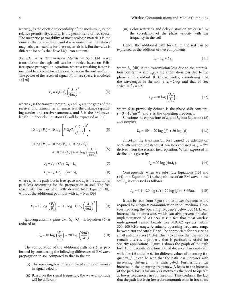
It can be seen from Figure 1 that lower frequencies arerequired for adequate communication in soil medium. How-ever, reducing the operating frequency below 300MHz willincrease the antenna size, which can also prevent practicalimplementation of WUSNs. It is a fact that most wirelessunderground sensor boards like MICA2 operate within300–400MHz range. A suitable operating frequency rangebetween 300 and 900MHz will be appropriate for preservingsmall antenna sizes [3, 34]. This is to ensure that the sensorsremain discrete, a property that is particularly useful forsecurity applications. Figure 1 shows the graph of the pathloss, Lp in decibels as a function of distance d in sandy soil
with ε′ = 4:5 and ε} = 0:1for different values of operating fre-quency, f . It can be seen that the path loss increases withincreasing distance, d, as anticipated. Furthermore, theincrease in the operating frequency, f , leads to the increaseof the path loss. This analysis motivates the need to operateat lower frequencies in soil medium. This confirms the factthat the path loss is far lower for communication in free space
4 Wireless Communications and Mobile Computing
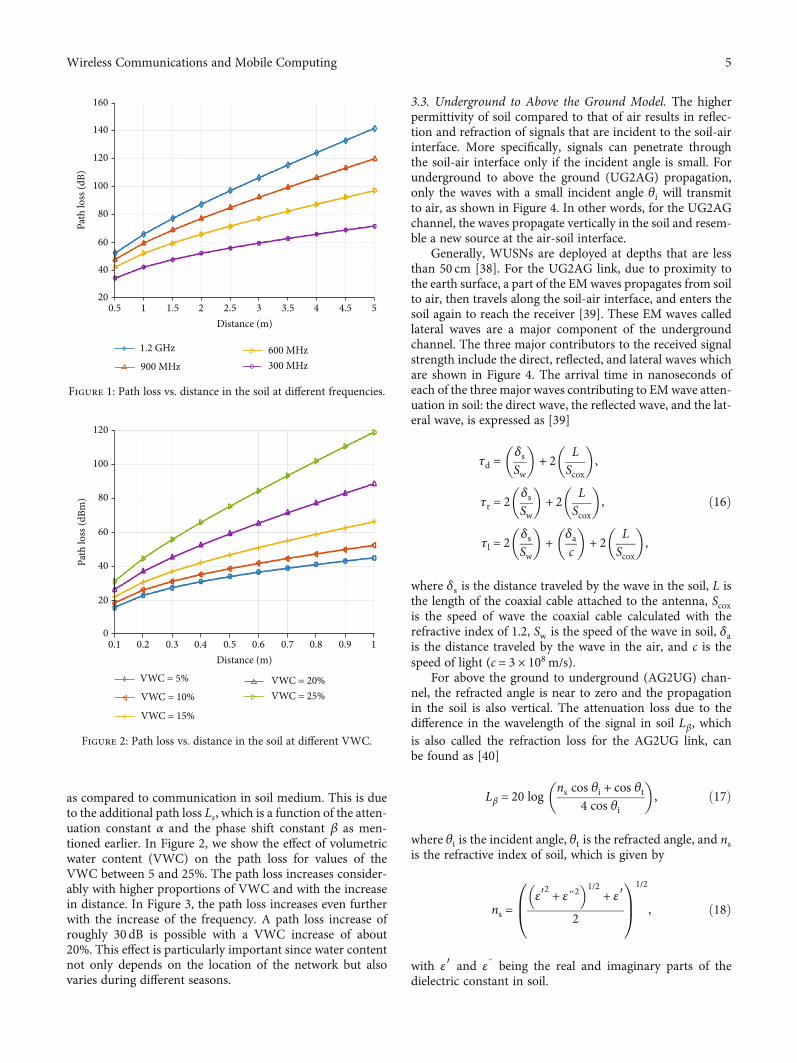
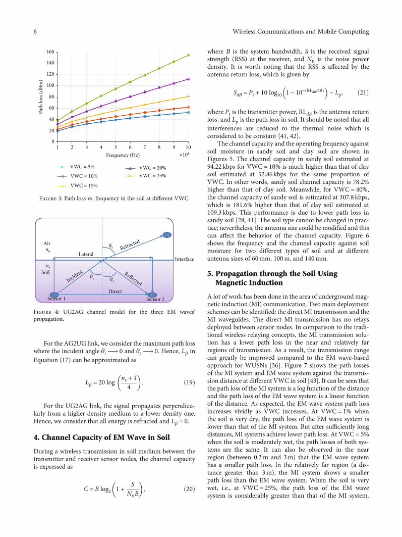
as compared to communication in soil medium. This is dueto the additional path loss Ls, which is a function of the atten-uation constant α and the phase shift constant β as men-tioned earlier. In Figure 2, we show the effect of volumetricwater content (VWC) on the path loss for values of theVWC between 5 and 25%. The path loss increases consider-ably with higher proportions of VWC and with the increasein distance. In Figure 3, the path loss increases even furtherwith the increase of the frequency. A path loss increase ofroughly 30 dB is possible with a VWC increase of about20%. This effect is particularly important since water contentnot only depends on the location of the network but alsovaries during different seasons.
3.3. Underground to Above the Ground Model. The higherpermittivity of soil compared to that of air results in reflec-tion and refraction of signals that are incident to the soil-airinterface. More specifically, signals can penetrate throughthe soil-air interface only if the incident angle is small. Forunderground to above the ground (UG2AG) propagation,only the waves with a small incident angle θi will transmitto air, as shown in Figure 4. In other words, for the UG2AGchannel, the waves propagate vertically in the soil and resem-ble a new source at the air-soil interface.
Generally, WUSNs are deployed at depths that are lessthan 50 cm [38]. For the UG2AG link, due to proximity tothe earth surface, a part of the EMwaves propagates from soilto air, then travels along the soil-air interface, and enters thesoil again to reach the receiver [39]. These EM waves calledlateral waves are a major component of the undergroundchannel. The three major contributors to the received signalstrength include the direct, reflected, and lateral waves whichare shown in Figure 4. The arrival time in nanoseconds ofeach of the three major waves contributing to EMwave atten-uation in soil: the direct wave, the reflected wave, and the lat-eral wave, is expressed as [39]
τd =δsSw
� �+ 2 L
Scox
� �,
τr = 2 δsSw
� �+ 2 L
Scox
� �,
τl = 2 δsSw
� �+ δa
c
� �+ 2 L
Scox
� �,
ð16Þ
where δs is the distance traveled by the wave in the soil, L isthe length of the coaxial cable attached to the antenna, Scoxis the speed of wave the coaxial cable calculated with therefractive index of 1.2, Sw is the speed of the wave in soil, δais the distance traveled by the wave in the air, and c is thespeed of light (c = 3 × 10⁸m/s).
For above the ground to underground (AG2UG) chan-nel, the refracted angle is near to zero and the propagationin the soil is also vertical. The attenuation loss due to thedifference in the wavelength of the signal in soil Lβ, whichis also called the refraction loss for the AG2UG link, canbe found as [40]
Lβ = 20 log ns cos θi + cos θt4 cos θi
� �, ð17Þ
where θi is the incident angle, θt is the refracted angle, and nsis the refractive index of soil, which is given by
ns =ε′2 + ε}2� �1/2
+ ε′2
0B@
1CA
1/2
, ð18Þ
with ε′ and ε} being the real and imaginary parts of thedielectric constant in soil.
0.520
40
60
80
Path
loss
(dB)
100
120
140
160
1.2 GHz
900 MHz600 MHz300 MHz
1 1.5 2 2.5 3 3.5 4 4.5 5Distance (m)
Figure 1: Path loss vs. distance in the soil at different frequencies.
0.10
20
40
60
80
Path
loss
(dBm
)
100
120
0.2 0.3 0.4 0.5Distance (m)
0.6 0.7 0.8 0.9 1
VWC = 5%
VWC = 10%
VWC = 15%
VWC = 20%VWC = 25%
+
Figure 2: Path loss vs. distance in the soil at different VWC.
5Wireless Communications and Mobile Computing
For the AG2UG link, we consider the maximum path losswhere the incident angle θi ⟶ 0 and θt ⟶ 0. Hence, Lβ inEquation (17) can be approximated as
Lβ = 20 log ns + 14
� �: ð19Þ
For the UG2AG link, the signal propagates perpendicu-larly from a higher density medium to a lower density one.Hence, we consider that all energy is refracted and Lβ = 0.
4. Channel Capacity of EM Wave in Soil
During a wireless transmission in soil medium between thetransmitter and receiver sensor nodes, the channel capacityis expressed as
C = B log2 1 + SN0B
� �, ð20Þ
where B is the system bandwidth, S is the received signalstrength (RSS) at the receiver, and N0 is the noise powerdensity. It is worth noting that the RSS is affected by theantenna return loss, which is given by
SdB = Pt + 10 log10 1 − 10− RLdB/10ð Þ� �
− Lp, ð21Þ
where Pt is the transmitter power, RLdB is the antenna returnloss, and Lp is the path loss in soil. It should be noted that allinterferences are reduced to the thermal noise which isconsidered to be constant [41, 42].
The channel capacity and the operating frequency againstsoil moisture in sandy soil and clay soil are shown inFigures 5. The channel capacity in sandy soil estimated at94.22 kbps for VWC = 10% is much higher than that of claysoil estimated at 52.86 kbps for the same proportion ofVWC. In other words, sandy soil channel capacity is 78.2%higher than that of clay soil. Meanwhile, for VWC = 40%,the channel capacity of sandy soil is estimated at 307.8 kbps,which is 181.6% higher than that of clay soil estimated at109.3 kbps. This performance is due to lower path loss insandy soil [28, 41]. The soil type cannot be changed in prac-tice; nevertheless, the antenna size could be modified and thiscan affect the behavior of the channel capacity. Figure 6shows the frequency and the channel capacity against soilmoisture for two different types of soil and at differentantenna sizes of 60mm, 100m, and 140mm.
5. Propagation through the Soil UsingMagnetic Induction
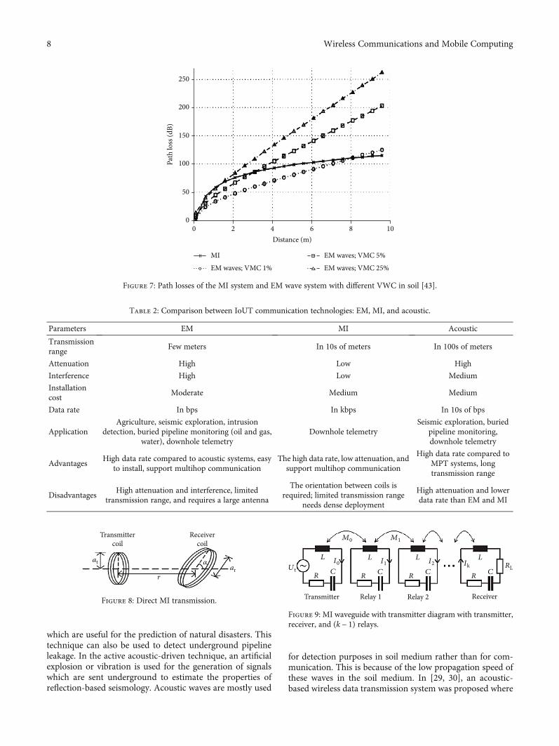
A lot of work has been done in the area of underground mag-netic induction (MI) communication. Two main deploymentschemes can be identified: the direct MI transmission and theMI waveguides. The direct MI transmission has no relaysdeployed between sensor nodes. In comparison to the tradi-tional wireless relaying concepts, the MI transmission solu-tion has a lower path loss in the near and relatively farregions of transmission. As a result, the transmission rangecan greatly be improved compared to the EM wave-basedapproach for WUSNs [36]. Figure 7 shows the path lossesof the MI system and EM wave system against the transmis-sion distance at different VWC in soil [43]. It can be seen thatthe path loss of the MI system is a log function of the distanceand the path loss of the EM wave system is a linear functionof the distance. As expected, the EM wave system path lossincreases vividly as VWC increases. At VWC = 1% whenthe soil is very dry, the path loss of the EM wave system islower than that of the MI system. But after sufficiently longdistances, MI systems achieve lower path loss. At VWC = 5%when the soil is moderately wet, the path losses of both sys-tems are the same. It can also be observed in the nearregion (between 0.3m and 3m) that the EM wave systemhas a smaller path loss. In the relatively far region (a dis-tance greater than 3m), the MI system shows a smallerpath loss than the EM wave system. When the soil is verywet, i.e., at VWC = 25%, the path loss of the EM wavesystem is considerably greater than that of the MI system.
10
20
40
60
80
100
120
Path
loss
(dBm
)
140
160
2 3 4 5 6Frequency (Hz)
7 8 9 10
VWC = 5%
VWC = 10%
VWC = 15%
VWC = 20%VWC = 25%
+
Figure 3: Path loss vs. frequency in the soil at different VWC.
Air
LateralInterface
na𝜃r
𝜃r𝜃i
nsSoil
Sensor 2Sensor 1Direct
Refracted
ReflectedIncident
Figure 4: UG2AG channel model for the three EM waves’propagation.
6 Wireless Communications and Mobile Computing
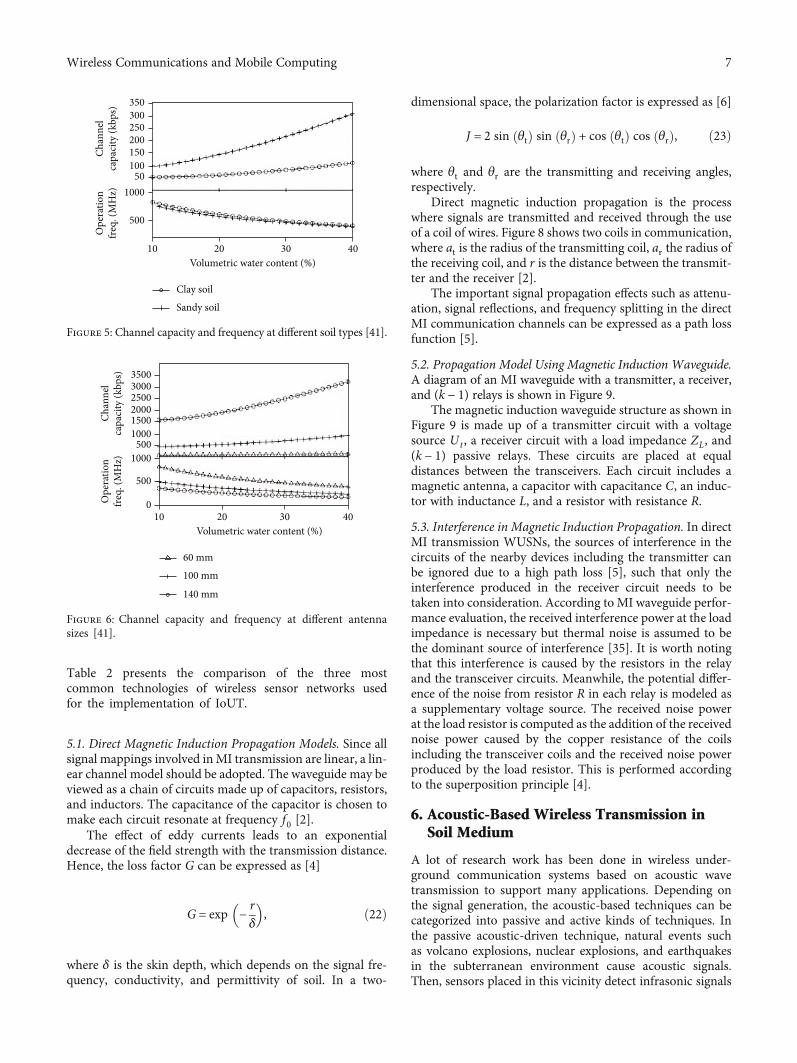
Table 2 presents the comparison of the three mostcommon technologies of wireless sensor networks usedfor the implementation of IoUT.
5.1. Direct Magnetic Induction Propagation Models. Since allsignal mappings involved inMI transmission are linear, a lin-ear channel model should be adopted. The waveguide may beviewed as a chain of circuits made up of capacitors, resistors,and inductors. The capacitance of the capacitor is chosen tomake each circuit resonate at frequency f0 [2].
The effect of eddy currents leads to an exponentialdecrease of the field strength with the transmission distance.Hence, the loss factor G can be expressed as [4]
G = exp −rδ
� �, ð22Þ
where δ is the skin depth, which depends on the signal fre-quency, conductivity, and permittivity of soil. In a two-
dimensional space, the polarization factor is expressed as [6]
J = 2 sin θtð Þ sin θrð Þ + cos θtð Þ cos θrð Þ, ð23Þ
where θt and θr are the transmitting and receiving angles,respectively.
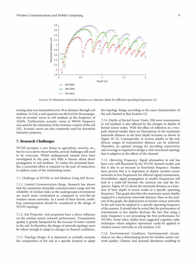
Direct magnetic induction propagation is the processwhere signals are transmitted and received through the useof a coil of wires. Figure 8 shows two coils in communication,where at is the radius of the transmitting coil, ar the radius ofthe receiving coil, and r is the distance between the transmit-ter and the receiver [2].
The important signal propagation effects such as attenu-ation, signal reflections, and frequency splitting in the directMI communication channels can be expressed as a path lossfunction [5].
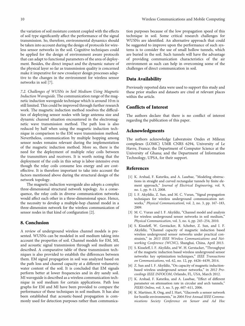
5.2. Propagation Model Using Magnetic Induction Waveguide.A diagram of an MI waveguide with a transmitter, a receiver,and (k − 1) relays is shown in Figure 9.
The magnetic induction waveguide structure as shown inFigure 9 is made up of a transmitter circuit with a voltagesource Ut , a receiver circuit with a load impedance ZL, and(k − 1) passive relays. These circuits are placed at equaldistances between the transceivers. Each circuit includes amagnetic antenna, a capacitor with capacitance C, an induc-tor with inductance L, and a resistor with resistance R.
5.3. Interference in Magnetic Induction Propagation. In directMI transmission WUSNs, the sources of interference in thecircuits of the nearby devices including the transmitter canbe ignored due to a high path loss [5], such that only theinterference produced in the receiver circuit needs to betaken into consideration. According to MI waveguide perfor-mance evaluation, the received interference power at the loadimpedance is necessary but thermal noise is assumed to bethe dominant source of interference [35]. It is worth notingthat this interference is caused by the resistors in the relayand the transceiver circuits. Meanwhile, the potential differ-ence of the noise from resistor R in each relay is modeled asa supplementary voltage source. The received noise powerat the load resistor is computed as the addition of the receivednoise power caused by the copper resistance of the coilsincluding the transceiver coils and the received noise powerproduced by the load resistor. This is performed accordingto the superposition principle [4].
6. Acoustic-Based Wireless Transmission inSoil Medium
A lot of research work has been done in wireless under-ground communication systems based on acoustic wavetransmission to support many applications. Depending onthe signal generation, the acoustic-based techniques can becategorized into passive and active kinds of techniques. Inthe passive acoustic-driven technique, natural events suchas volcano explosions, nuclear explosions, and earthquakesin the subterranean environment cause acoustic signals.Then, sensors placed in this vicinity detect infrasonic signals
10
500
100050
100150200250300350
Ope
ratio
nfre
q. (M
Hz)
Chan
nel
capa
city
(kbp
s)
20
Clay soil
Sandy soil
30 40Volumetric water content (%)
Figure 5: Channel capacity and frequency at different soil types [41].
10
500
0
1000500
100015002000250030003500
Ope
ratio
nfre
q. (M
Hz)
Chan
nel
capa
city
(kbp
s)
20
60 mm
100 mm
30 40Volumetric water content (%)
140 mm
Figure 6: Channel capacity and frequency at different antennasizes [41].
7Wireless Communications and Mobile Computing
which are useful for the prediction of natural disasters. Thistechnique can also be used to detect underground pipelineleakage. In the active acoustic-driven technique, an artificialexplosion or vibration is used for the generation of signalswhich are sent underground to estimate the properties ofreflection-based seismology. Acoustic waves are mostly used
for detection purposes in soil medium rather than for com-munication. This is because of the low propagation speed ofthese waves in the soil medium. In [29, 30], an acoustic-based wireless data transmission system was proposed where
00
50
100
150
Path
loss
(dB)
200
250
2 4 6Distance (m)
8 10
MI
EM waves; VMC 1%
EM waves; VMC 5%
EM waves; VMC 25%
Figure 7: Path losses of the MI system and EM wave system with different VWC in soil [43].
Table 2: Comparison between IoUT communication technologies: EM, MI, and acoustic.
Parameters EM MI Acoustic
Transmissionrange
Few meters In 10s of meters In 100s of meters
Attenuation High Low High
Interference High Low Medium
Installationcost
Moderate Medium Medium
Data rate In bps In kbps In 10s of bps
ApplicationAgriculture, seismic exploration, intrusion
detection, buried pipeline monitoring (oil and gas,water), downhole telemetry
Downhole telemetrySeismic exploration, buried
pipeline monitoring,downhole telemetry
AdvantagesHigh data rate compared to acoustic systems, easy
to install, support multihop communicationThe high data rate, low attenuation, and
support multihop communication
High data rate compared toMPT systems, longtransmission range
DisadvantagesHigh attenuation and interference, limited
transmission range, and requires a large antenna
The orientation between coils isrequired; limited transmission range
needs dense deployment
High attenuation and lowerdata rate than EM and MI
Transmittercoil
atar
r
𝛼
Receivercoil
Figure 8: Direct MI transmission.
M0
I0Ut
L
CR
I1L
CR
Transmitter Relay 1 Relay 2 Receiver
I2L
CR
Ik RL
L
CR
M1
Figure 9: MI waveguide with transmitter diagram with transmitter,receiver, and (k − 1) relays.
8 Wireless Communications and Mobile Computing
sensing data was transmitted over 30m distance through soilmedium. In [44], a soil equation was derived for the propaga-tion of acoustic waves in soil medium at the frequency of16 kHz. Furthermore, acoustic waves at 900Hz frequencywas used for the estimation of the moisture content of the soil[45]. Acoustic waves are also commonly used for downholetelemetry purposes.
7. Research Challenges
WUSN promises a new future in agriculture, security, etc.,but for us to derive those benefits, several challenges still needto be overcome. Whilst underground tunnels have beeninvestigated in the past, very little is known about directpropagation in soil medium. To realize the promised bene-fits, a concerted effort is required on the part of researchersto address some of the outstanding issues.
7.1. Challenges of WUSNs in Soil Medium Using EM Waves
7.1.1. Limited Communication Range. Research has shownthat the maximum attainable communication range and thereliability of wireless links in the underground environmentare much more constrained as compared to over-the-airwireless sensor networks. As a result of these factors, multi-hop communication should be considered in the design ofWUSN topology.
7.1.2. Soil Properties. Soil properties have a direct influenceon the wireless sensor network performance. Transmissionquality is greatly hampered by the increase of water contentin the soil. So therefore, the design of network topology mustbe robust enough to adapt to changes in channel conditions.
7.1.3. Topology Design. It is important to carefully examinethe composition of the soil at a specific location to adapt
the topology design according to the exact characteristics ofthe soil channel at that location [2].
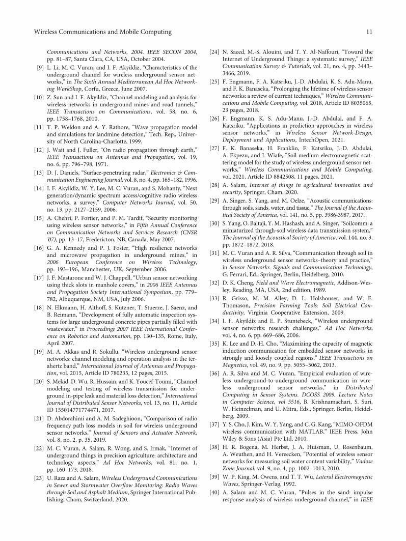
7.1.4. Depths of Buried Sensor Nodes. EM wave transmissionin soil medium is also affected by the changes in depths ofburied sensor nodes. With the effect of reflection in a two-path channel model, there are fluctuations in the maximuminternode distance as the bury depth increases as shown inFigure 10 [3]. Consequently, at various depths in the soil,diverse ranges of transmission distance can be achieved.Therefore, an optimal strategy for providing connectivityand coverage is required to design a well-structured topologythat is adaptive to the effects of the channel.
7.1.5. Operating Frequency. Signal attenuation in soil hasbeen very well illustrated by the WUSN channel model, andthis is due to an increase in functional frequency. Studieshave proven that it is important to deploy wireless sensornetworks at low frequencies for efficient signal transmission.Nevertheless, signal propagation at smaller frequencies willlead to a trade-off between the antenna size and the fre-quency. Figure 10 [3] shows the internode distance as a func-tion of bury depth of sensor nodes at a specific operatingfrequency. This graph describes the maximum sensor depthsmapped to a maximum internode distance. Base on the anal-ysis of the graph, the deployment of wireless sensor networksin the soil must be adapted to a specific operating frequencyof the sensors. It should also be noted that the performance oftransmission at low depths discloses the fact that using astatic frequency is not promoting the best performance forWUSNs. Some other studies have suggested cognitive radiotechniques where adaptive operations could be applied towireless sensor networks in soil medium [14].
7.1.6. Environmental Conditions. Environmental circum-stances are also a determining factor for wireless sensor net-work quality. Climatic and seasonal alterations resulting in
1.80 0.5 1
Depth (m)1.5
300 MHz400 MHz
700 MHz
2
2
2.2
2.4
2.6
Max
imum
dist
ance
(m)
2.8
3
3.2
3.4
3.6
3.8
Figure 10: Maximum internode distance as a function depth for different operating frequencies [3].
9Wireless Communications and Mobile Computing
the variation of soil moisture content coupled with the effectsof soil type significantly affect the performance of the signaltransmission. So, therefore, environmental dynamics shouldbe taken into account during the design of protocols for wire-less sensor networks in the soil. Cognitive techniques couldbe applied for the design of environment aware protocolsthat can adapt to functional parameters of the area of deploy-ment. Besides, the direct impact and the dynamic nature ofthe physical layer so far as transmission quality is concernedmake it imperative for new crosslayer design processes adap-tive to the changes in the environment for wireless sensornetworks in soil [7].
7.2. Challenges of WUSNs in Soil Medium Using MagneticInductionWaveguide. The communication range of the mag-netic induction waveguide technique which is around 10m isstill limited. This could be improved through further researchwork. The magnetic induction method resolves the difficul-ties of deploying sensor nodes with large antenna size anddynamic channel situation encountered in the electromag-netic wave transmission method. The path loss is alsoreduced by half when using the magnetic induction tech-nique in comparison to the EM wave transmission method.Nevertheless, communication by multiple hopping amongsensor nodes remains relevant during the implementationof the magnetic induction method. More so, there is theneed for the deployment of multiple relay coils betweenthe transmitters and receivers. It is worth noting that thedeployment of the coils in this setup is labor-intensive eventhough the relay coils consume less energy and are cost-effective. It is therefore important to take into account thefactors mentioned above during the structural design of thenetwork topology.
The magnetic induction waveguide also adopts a complexthree-dimensional structural network topology. As a conse-quence, the relay coils in diverse communication networkswould affect each other in a three-dimensional space. Hence,the necessity to develop a multiple-hop channel model in athree-dimension network for the wireless communication ofsensor nodes in that kind of configuration [2].
8. Conclusion
A review of underground wireless channel models is pre-sented. WUSNs can be modeled in soil medium taking intoaccount the properties of soil. Channel models for EM, MI,and acoustic signal transmission through soil medium aredescribed. A comparative table of these transmission tech-niques is also provided to establish the differences betweenthem. EM signal propagation in soil was analyzed based onthe path loss and channel capacity at a different volumetricwater content of the soil. It is concluded that EM signalsperform better at lower frequencies and in dry sandy soil.MI waveguide is described as a wireless communication tech-nique in soil medium for certain applications. Path lossgraphs for EM and MI have been provided to compare theperformance of these techniques in soil medium. It has alsobeen established that acoustic-based propagation is com-monly used for detection purposes rather than communica-
tion purposes because of the low propagation speed of thistechnique in soil. Some critical research challenges forWUSNs are identified. An alternative approach that couldbe suggested to improve upon the performance of such sys-tems is to consider the use of small hollow tunnels, whichare buried in the soil. Such tunnels will have the advantageof providing communication characteristics of the airenvironment as such can help in overcoming some of thechallenges of direct communication in soil.
Data Availability
Previously reported data were used to support this study andthese prior studies and datasets are cited at relevant placeswithin the article.
Conflicts of Interest
The authors declare that there is no conflict of interestregarding the publication of this paper.
Acknowledgments
The authors acknowledge Laboratoire Ondes et Milieuxcomplexes (LOMC) UMR CNRS 6294, University of LeHavre, France; the Department of Computer Science at theUniversity of Ghana; and the Department of InformationTechnology, UPSA, for their support.
References
[1] K. Arshad, F. Katsriku, and A. Lasebae, “Modeling obstruc-tions in straight and curved rectangular tunnels by finite ele-ment approach,” Journal of Electrical Engineering, vol. 9,no. 1, pp. 9–13, 2008.
[2] I. F. Akyildiz, Z. Sun, and M. C. Vuran, “Signal propagationtechniques for wireless underground communication net-works,” Physical Communicationl, vol. 2, no. 3, pp. 167–183,2009.
[3] M. C. Vuran and I. F. Akyildiz, “Channel model and analysisfor wireless underground sensor networks in soil medium,”Physical Communication, vol. 3, no. 4, pp. 245–254, 2010.
[4] S. Kisseleff, W. Gerstacker, R. Schober, Z. Sun, and I. F.Akyildiz, “Channel capacity of magnetic induction basedwireless underground sensor networks under practical con-straints,” in 2013 IEEE Wireless Communications and Net-working Conference (WCNC), Shanghai, China, April 2013.
[5] S. Kisseleff, I. F. Akyildiz, and W. H. Gerstacker, “Throughputof the magnetic induction based wireless underground sensornetworks: key optimization techniques,” IEEE Transactionson Communications, vol. 62, no. 12, pp. 4426–4439, 2014.
[6] Z. Sun and I. F. Akyildiz, “On capacity of magnetic induction-based wireless underground sensor networks,” in 2012 Pro-ceedings IEEE INFOCOM, Orlando, FL, USA, March 2012.
[7] K. Arshad, F. Katsriku, and A. Lasebae, “Effect of differentparameter on attenuation rate in circular and arch tunnels,”PIERS Online, vol. 3, no. 5, pp. 607–611, 2006.
[8] K. Martinez, R. Ong, and J. Hart, “Glacsweb: a sensor networkfor hostile environments,” in 2004 First Annual IEEE Commu-nications Society Conference on Sensor and Ad Hoc
10 Wireless Communications and Mobile Computing
Communications and Networks, 2004. IEEE SECON 2004,pp. 81–87, Santa Clara, CA, USA, October 2004.
[9] L. Li, M. C. Vuran, and I. F. Akyildiz, “Characteristics of theunderground channel for wireless underground sensor net-works,” in The Sixth Annual Mediterranean Ad Hoc Network-ing WorkShop, Corfu, Greece, June 2007.
[10] Z. Sun and I. F. Akyildiz, “Channel modeling and analysis forwireless networks in underground mines and road tunnels,”IEEE Transactions on Communications, vol. 58, no. 6,pp. 1758–1768, 2010.
[11] T. P. Weldon and A. Y. Rathore, “Wave propagation modeland simulations for landmine detection,” Tech. Rep., Univer-sity of North Carolina-Charlotte, 1999.
[12] J. Wait and J. Fuller, “On radio propagation through earth,”IEEE Transactions on Antennas and Propagation, vol. 19,no. 6, pp. 796–798, 1971.
[13] D. J. Daniels, “Surface-penetrating radar,” Electronics & Com-munication Engineering Journal, vol. 8, no. 4, pp. 165–182, 1996.
[14] I. F. Akyildiz, W. Y. Lee, M. C. Vuran, and S. Mohanty, “Nextgeneration/dynamic spectrum access/cognitive radio wirelessnetworks, a survey,” Computer Networks Journal, vol. 50,no. 13, pp. 2127–2159, 2006.
[15] A. Chehri, P. Fortier, and P. M. Tardif, “Security monitoringusing wireless sensor networks,” in Fifth Annual Conferenceon Communication Networks and Services Research (CNSR'07), pp. 13–17, Fredericton, NB, Canada, May 2007.
[16] G. A. Kennedy and P. J. Foster, “High resilience networksand microwave propagation in underground mines,” in2006 European Conference on Wireless Technology,pp. 193–196, Manchester, UK, September 2006.
[17] J. F. Mastarone and W. J. Chappell, “Urban sensor networkingusing thick slots in manhole covers,” in 2006 IEEE Antennasand Propagation Society International Symposium, pp. 779–782, Albuquerque, NM, USA, July 2006.
[18] N. Elkmann, H. Althoff, S. Kutzner, T. Stuerze, J. Saenz, andB. Reimann, “Development of fully automatic inspection sys-tems for large underground concrete pipes partially filled withwastewater,” in Proceedings 2007 IEEE International Confer-ence on Robotics and Automation, pp. 130–135, Rome, Italy,April 2007.
[19] M. A. Akkas and R. Sokullu, “Wireless underground sensornetworks: channel modeling and operation analysis in the ter-ahertz band,” International Journal of Antennas and Propaga-tion, vol. 2015, Article ID 780235, 12 pages, 2015.
[20] S. Mekid, D. Wu, R. Hussain, and K. Youcef-Toumi, “Channelmodeling and testing of wireless transmission for under-ground in-pipe leak and material loss detection,” InternationalJournal of Distributed Sensor Networks, vol. 13, no. 11, ArticleID 155014771774471, 2017.
[21] D. Abdorahimi and A. M. Sadeghioon, “Comparison of radiofrequency path loss models in soil for wireless undergroundsensor networks,” Journal of Sensors and Actuator Network,vol. 8, no. 2, p. 35, 2019.
[22] M. C. Vuran, A. Salam, R. Wong, and S. Irmak, “Internet ofunderground things in precision agriculture: architecture andtechnology aspects,” Ad Hoc Networks, vol. 81, no. 1,pp. 160–173, 2018.
[23] U. Raza and A. Salam,Wireless Underground Communicationsin Sewer and Stormwater Overflow Monitoring: Radio Wavesthrough Soil and Asphalt Medium, Springer International Pub-lishing, Cham, Switzerland, 2020.
[24] N. Saeed, M.-S. Alouini, and T. Y. Al-Naffouri, “Toward theInternet of Underground Things: a systematic survey,” IEEECommunication Survey & Tutorials, vol. 21, no. 4, pp. 3443–3466, 2019.
[25] F. Engmann, F. A. Katsriku, J.-D. Abdulai, K. S. Adu-Manu,and F. K. Banaseka, “Prolonging the lifetime of wireless sensornetworks: a review of current techniques,”Wireless Communi-cations and Mobile Computing, vol. 2018, Article ID 8035065,23 pages, 2018.
[26] F. Engmann, K. S. Adu-Manu, J.-D. Abdulai, and F. A.Katsriku, “Applications in prediction approaches in wirelesssensor networks,” in Wireless Sensor Network-Design,Deployment and Applications, IntechOpen, 2021.
[27] F. K. Banaseka, H. Franklin, F. Katsriku, J.-D. Abdulai,A. Ekpezu, and I. Wiafe, “Soil medium electromagnetic scat-tering model for the study of wireless underground sensor net-works,” Wireless Communications and Mobile Computing,vol. 2021, Article ID 8842508, 11 pages, 2021.
[28] A. Salam, Internet of things in agricultural innovation andsecurity, Springer, Cham, 2020.
[29] A. Singer, S. Yang, and M. Oelze, “Acoustic communications:through soils, sands, water, and tissue,” The Journal of the Acous-tical Society of America, vol. 141, no. 5, pp. 3986-3987, 2017.
[30] S. Yang, O. Baltaji, Y. M. Hashash, and A. Singer, “Soilcomm: aminiaturized through-soil wireless data transmission system,”The Journal of the Acoustical Society of America, vol. 144, no. 3,pp. 1872–1872, 2018.
[31] M. C. Vuran and A. R. Silva, “Communication through soil inwireless underground sensor networks–theory and practice,”in Sensor Networks. Signals and Communication Technology,G. Ferrari, Ed., Springer, Berlin, Heidelberg, 2010.
[32] D. K. Cheng, Field and Wave Electromagnetic, Addison-Wes-ley, Reading, MA, USA, 2nd edition, 1989.
[33] R. Grisso, M. M. Alley, D. L. Holshouser, and W. E.Thomason, Precision Farming Tools: Soil Electrical Con-ductivity, Virginia Cooperative Extension, 2009.
[34] I. F. Akyildiz and E. P. Stuntebeck, “Wireless undergroundsensor networks: research challenges,” Ad Hoc Networks,vol. 4, no. 6, pp. 669–686, 2006.
[35] K. Lee and D.-H. Cho, “Maximizing the capacity of magneticinduction communication for embedded sensor networks instrongly and loosely coupled regions,” IEEE Transactions onMagnetics, vol. 49, no. 9, pp. 5055–5062, 2013.
[36] A. R. Silva and M. C. Vuran, “Empirical evaluation of wire-less underground-to-underground communication in wire-less underground sensor networks,” in DistributedComputing in Sensor Systems. DCOSS 2009. Lecture Notesin Computer Science, vol 5516, B. Krishnamachari, S. Suri,W. Heinzelman, and U. Mitra, Eds., Springer, Berlin, Heidel-berg, 2009.
[37] Y. S. Cho, J. Kim,W. Y. Yang, and C. G. Kang, “MIMO-OFDMwireless communication with MATLAB,” IEEE Press, JohnWiley & Sons (Asia) Pte Ltd, 2010.
[38] H. R. Bogena, M. Herbst, J. A. Huisman, U. Rosenbaum,A. Weuthen, and H. Vereecken, “Potential of wireless sensornetworks for measuring soil water content variability,” VadoseZone Journal, vol. 9, no. 4, pp. 1002–1013, 2010.
[39] W. P. King, M. Owens, and T. T. Wu, Lateral ElectromagneticWaves, Springer-Verlag, 1992.
[40] A. Salam and M. C. Vuran, “Pulses in the sand: impulseresponse analysis of wireless underground channel,” in IEEE
11Wireless Communications and Mobile Computing
INFOCOM 2016 - The 35th Annual IEEE International Confer-ence on Computer Communications, San Francisco, CA, USA,April 2016.
[41] A. Salam and U. Raza, “Underground wireless channel band-width and capacity,” in Signals in the Soil, Springer, Cham,2020.
[42] A. Salam, “Design of subsurface phased array antennas fordigital agriculture applications,” in 2019 IEEE InternationalSymposium on Phased Array System & Technology (PAST),Waltham, MA, USA, October 2019.
[43] Z. Sun and I. F. Akyildiz, “Magnetic induction communica-tions for wireless underground sensor networks,” IEEETransactions on Antennas and Propagation, vol. 58, no. 7,pp. 2426–2435, 2010.
[44] R. Freire, M. H. M. de Abreu, R. Y. Okada, P. F. Soares, andC. R. Granhen Tavares, “Sound absorption coefficient in situ:an alternative for estimating soil loss factors,” UltrasonicsSonochemistry, vol. 22, pp. 100–107, 2015.
[45] R. Sharma and A. Gupta, “Continuous-wave acoustic methodfor determination of moisture content in agricultural soil,”Computers and Electronics in Agriculture, vol. 73, no. 2,pp. 105–111, 2010.
12 Wireless Communications and Mobile Computing