Embed Size (px)
Citation preview

SIGNAL DESIGN

MARYLAND STATE HIGHWAY ADMINISTRATION
Office of Traffic and Safety Traffic Engineering Design Division
Traffic Control Devices Design Manual
July 2017 1
SIGNAL DESIGN
DATA COLLECTION
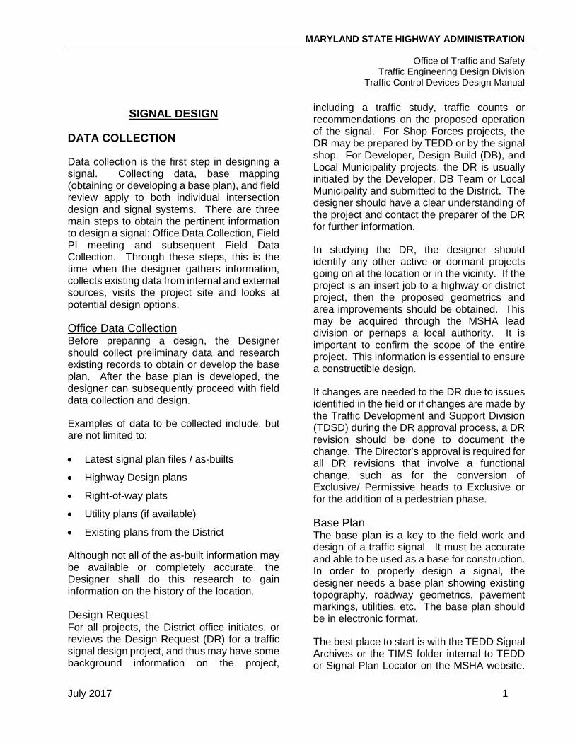
Data collection is the first step in designing a signal. Collecting data, base mapping (obtaining or developing a base plan), and field review apply to both individual intersection design and signal systems. There are three main steps to obtain the pertinent information to design a signal: Office Data Collection, Field PI meeting and subsequent Field Data Collection. Through these steps, this is the time when the designer gathers information, collects existing data from internal and external sources, visits the project site and looks at potential design options.
Office Data Collection Before preparing a design, the Designer should collect preliminary data and research existing records to obtain or develop the base plan. After the base plan is developed, the designer can subsequently proceed with field data collection and design.
Examples of data to be collected include, but are not limited to:
• Latest signal plan files / as-builts
• Highway Design plans
• Right-of-way plats
• Utility plans (if available)
• Existing plans from the District
Although not all of the as-built information may be available or completely accurate, the Designer shall do this research to gain information on the history of the location.
Design Request For all projects, the District office initiates, or reviews the Design Request (DR) for a traffic signal design project, and thus may have some background information on the project,
including a traffic study, traffic counts or recommendations on the proposed operation of the signal. For Shop Forces projects, the DR may be prepared by TEDD or by the signal shop. For Developer, Design Build (DB), and Local Municipality projects, the DR is usually initiated by the Developer, DB Team or Local Municipality and submitted to the District. The designer should have a clear understanding of the project and contact the preparer of the DR for further information.
In studying the DR, the designer should identify any other active or dormant projects going on at the location or in the vicinity. If the project is an insert job to a highway or district project, then the proposed geometrics and area improvements should be obtained. This may be acquired through the MSHA lead division or perhaps a local authority. It is important to confirm the scope of the entire project. This information is essential to ensure a constructible design.
If changes are needed to the DR due to issues identified in the field or if changes are made by the Traffic Development and Support Division (TDSD) during the DR approval process, a DR revision should be done to document the change. The Director’s approval is required for all DR revisions that involve a functional change, such as for the conversion of Exclusive/ Permissive heads to Exclusive or for the addition of a pedestrian phase.
Base Plan The base plan is a key to the field work and design of a traffic signal. It must be accurate and able to be used as a base for construction. In order to properly design a signal, the designer needs a base plan showing existing topography, roadway geometrics, pavement markings, utilities, etc. The base plan should be in electronic format.
The best place to start is with the TEDD Signal Archives or the TIMS folder internal to TEDD or Signal Plan Locator on the MSHA website.
MARYLAND STATE HIGHWAY ADMINISTRATION
Office of Traffic and Safety Traffic Engineering Design Division
Traffic Control Devices Design Manual
July 2017 2
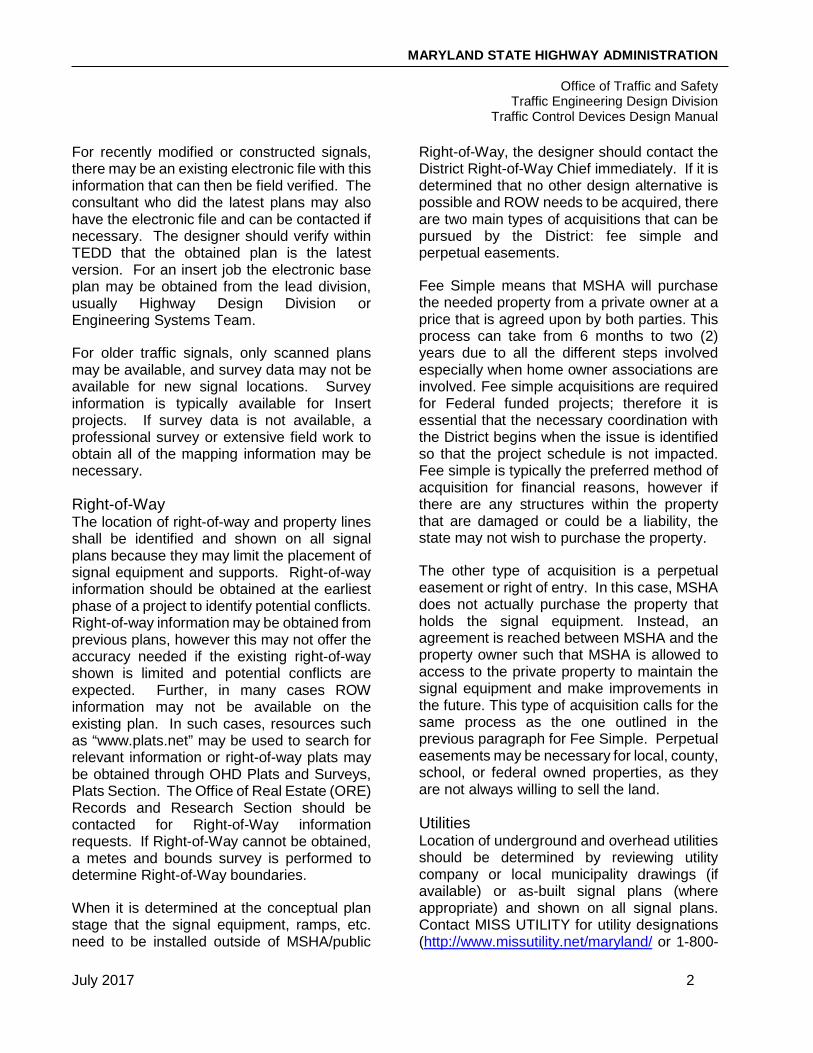
For recently modified or constructed signals, there may be an existing electronic file with this information that can then be field verified. The consultant who did the latest plans may also have the electronic file and can be contacted if necessary. The designer should verify within TEDD that the obtained plan is the latest version. For an insert job the electronic base plan may be obtained from the lead division, usually Highway Design Division or Engineering Systems Team.
For older traffic signals, only scanned plans may be available, and survey data may not be available for new signal locations. Survey information is typically available for Insert projects. If survey data is not available, a professional survey or extensive field work to obtain all of the mapping information may be necessary.
Right-of-Way The location of right-of-way and property lines shall be identified and shown on all signal plans because they may limit the placement of signal equipment and supports. Right-of-way information should be obtained at the earliest phase of a project to identify potential conflicts. Right-of-way information may be obtained from previous plans, however this may not offer the accuracy needed if the existing right-of-way shown is limited and potential conflicts are expected. Further, in many cases ROW information may not be available on the existing plan. In such cases, resources such as “www.plats.net” may be used to search for relevant information or right-of-way plats may be obtained through OHD Plats and Surveys, Plats Section. The Office of Real Estate (ORE) Records and Research Section should be contacted for Right-of-Way information requests. If Right-of-Way cannot be obtained, a metes and bounds survey is performed to determine Right-of-Way boundaries.
When it is determined at the conceptual plan stage that the signal equipment, ramps, etc. need to be installed outside of MSHA/public
Right-of-Way, the designer should contact the District Right-of-Way Chief immediately. If it is determined that no other design alternative is possible and ROW needs to be acquired, there are two main types of acquisitions that can be pursued by the District: fee simple and perpetual easements.
Fee Simple means that MSHA will purchase the needed property from a private owner at a price that is agreed upon by both parties. This process can take from 6 months to two (2) years due to all the different steps involved especially when home owner associations are involved. Fee simple acquisitions are required for Federal funded projects; therefore it is essential that the necessary coordination with the District begins when the issue is identified so that the project schedule is not impacted. Fee simple is typically the preferred method of acquisition for financial reasons, however if there are any structures within the property that are damaged or could be a liability, the state may not wish to purchase the property.
The other type of acquisition is a perpetual easement or right of entry. In this case, MSHA does not actually purchase the property that holds the signal equipment. Instead, an agreement is reached between MSHA and the property owner such that MSHA is allowed to access to the private property to maintain the signal equipment and make improvements in the future. This type of acquisition calls for the same process as the one outlined in the previous paragraph for Fee Simple. Perpetual easements may be necessary for local, county, school, or federal owned properties, as they are not always willing to sell the land.
Utilities Location of underground and overhead utilities should be determined by reviewing utility company or local municipality drawings (if available) or as-built signal plans (where appropriate) and shown on all signal plans. Contact MISS UTILITY for utility designations (http://www.missutility.net/maryland/ or 1-800-

MARYLAND STATE HIGHWAY ADMINISTRATION
Office of Traffic and Safety Traffic Engineering Design Division
Traffic Control Devices Design Manual
July 2017 3
257-7777) for all projects a minimum of 15 days prior to a field PI meeting. When performing the field inventory of marked utilities, do not assume that all utilities have been identified. Stormwater and sewer are not typically marked, so the designer should check with the county for more information, and additional field survey is required.
Field PI A field preliminary investigation (PI) meeting is required for State originated projects such as Areawide and Insert projects. It is also suggested that a field PI meeting be conducted for Developer and Design Build projects. This is to confirm the DR, identify issues in the field which may increase costs and cause delay to the project and to minimize revisions at the PS&E stage.
The PI meeting should be set up by the MSHA TEDD Project Manager and should involve at a minimum the Project Manager, the Team Leader if the Project Manager is a consultant, the Construction Inspector, the designer, and the DR preparer. The Office of Highway Development ADA representative should also be invited to the meeting if any ADA upgrades are proposed, such as for APS/CPS projects and ADA upgrade projects.
Participating parties should:
• Discuss conceptual locations for the proposed signal equipment and potential design options.
• Review sidewalk and sidewalk ramp concepts.
• Identify which quadrants may or may not suit the cabinet or signal structures and determine what types of equipment are appropriate for the location.
• Discuss existing and proposed features which may present design challenges.
• Locate potential power feeds and areas with strong cellular service.
• Identify if there are any constraints for laying conduit and placing handholes.
• Identify if this location meets criteria for uninterruptible power supply (UPS).
By selecting pole locations in the field, you can avoid conflicting physical features that may not show up on as-built plans or utility drawings. By spotting the location of signal heads, you can ensure that they are not in conflict with other signals or overhead signs (where modifications to an existing signalized intersection are planned), that adequate visibility is available, and can determine whether optically programmed heads are necessary to shield the indications from conflicting traffic. After the field meeting, the designer should prepare PI meeting minutes and can now prepare a Conceptual Design Plan/Layout.
Field Data Collection Data collected in the office should always be field reviewed and verified and new information (or information that could not be found) should be obtained by field data collection.
Field Survey The limits of the site review on each approach are usually determined by the location of advance signing, placement of advance detectors, length of turn bays, limits of existing base plans, and signal system limits, whichever is greater.
Survey Methods There are two main survey methods to collect existing survey/base plan information. The method used will vary depending on the information required for a specific project.
• Professional Survey – A professional survey involves the hiring of an outside company or MSHA survey forces to collect the field information and mapping. A professional topographically survey may be needed on a case-by-case basis. This is the most accurate, all-encompassing

MARYLAND STATE HIGHWAY ADMINISTRATION
Office of Traffic and Safety Traffic Engineering Design Division
Traffic Control Devices Design Manual
July 2017 4
method to collect field data, but is typically the most expensive and time consuming.
When right-of-way data collected during office data collection is not adequate, a metes and bounds survey may be requested through OHD Plats & Surveys, Survey Section. A topographic survey should be simultaneously requested in order to get all pertinent data.
• Tape and Wheel – The designer or designated person does a tape and wheel survey. This is the simple method of visiting the project site and using tape measures, wheels and/or other measuring devices to collect critical information. Using this method information may be collected on lane widths, lane lengths, pole size, locations and sizes of structures, sign sizes, etc. The data collected shall be documented.
Initial Site Visit Most of the necessary information should be obtained during the initial site visit. The existing base plan should be verified and additional information should be collected to prepare for the proposed signal design.
Existing information to be collected should include at a minimum:
• Existing signal equipment
• Pavement markings
• Signing
• Other traffic control devices and ITS equipment
• Road alignment and geometrics
• Sidewalks, handicap ramps, and ADA compliance
• Utilities (overhead and underground)
• Drainage elements (ditches, pipes, and structures)
• Driveway entrances / exits
• Buildings and setback
• Fences and walls
• Traffic barriers
• Trees and vegetation
Existing Signal Equipment If there is an existing signal, then collect information on the signal pole structures and configurations, type of cabinet and controller, detection system and signal heads. Determine what equipment may be reused and what needs to be replaced.
Type and number of detection equipment in the cabinet should be determined (rack / shelf mounted detector amplifiers or video detector interface). Wiring sizes and number of conductors should be verified. Information on interconnect and wireless communication should also be collected as well as the location of electrical service feed. Associated utility poles and/or transformers should be identified on the plan with owner’s name and pole/transformer identification number.
Check handholes for concrete collars and proper grounding of the frame and cover. Open handholes and check conduit if new wiring will be necessary to verify if existing conduits can be used. Verify if additional knock-outs are present for the installation of new conduit. Check for ground rods in handholes closest to the signal structure. If the existing handhole does not have the items listed, they should be incorporated into the design. Make note of location and fill of handholes and of existing wire in conduits so the conduit fill capacity is not exceeded with new wire. The designer is responsible for checking that the cable is loose and that space is available within the conduit. In locations where new ADA ramps or sidewalk are being installed or existing ramps are being redone, consideration should be given to how the handholes can be lowered. If the handholes are brick, they can be lowered by removing rows of brick. If the handholes are

MARYLAND STATE HIGHWAY ADMINISTRATION
Office of Traffic and Safety Traffic Engineering Design Division
Traffic Control Devices Design Manual
July 2017 5
concrete, they can be lowered to the precast concrete base. However, if the lid and cover are already resting directly on the precast concrete base, adjusting the handhole to grade may be more challenging during construction. If handholes are filled with water, they may still be reusable. However, if the handhole is filled with water above the conduits, it is not recommended to reuse.
Road Alignment and Geometrics Road alignment (vertical/horizontal) should be noted, along with intersection skew and channelization islands if any. Collect information on lane configuration/use (left/thru /right turn lanes) and widths and turn bay lengths. Note locations of open/closed section as well as presence of on-street parking, parking restrictions, and bus stops.
Utility Locations Verify utility locations in the field, including location of the proposed electrical feed. Underground utilities shall be picked up in the field by using Miss Utility or professional survey.
Locate and measure the heights of overhead utilities, particularly at the lowest point of overhead utility and any other potential conflict points. This will allow for meeting the NESC and the Maryland High Voltage-line Act requirements for utility clearances and avoiding any conflicts between the proposed signal and existing utilities. These measurements shall be documented and shown on the signal plan in areas that will have points of crossings with signal equipment.
Measuring overhead utility heights is a critical element in the site visit, but it is also the most hazardous. Measuring the height of utilities is commonly done using an overhead cable measuring rod made of fiberglass. The rod is used to measure the height of the different overhead utilities from the ground. DO NOT measure the primary electric lines with the rod due to hazardous high voltage. Further, do not
attempt to measure any lines with the rod unless with someone who is trained and experienced.
Another method used for measuring utility heights is a Teleheight. This is a safer method of measuring heights. See Figure SG.1.
Figure SG. 1 - Using a Teleheight; Source Hubbell Power Systems
It is important to make note of any fuses, transformers, splice boxes or insulators on the utility pole. This will help in identifying what types of lines are on the pole. For instance, generally fuses are located between primary distribution lines and a transformer. The secondary (power feed) lines are usually located directly below the transformer. When noting transformers, the number of cables leaving the transformer should be observed. If two cables are leaving the transformer, it is a single phase, which means that power can be used for the signal. If there are three cables leaving the transformer, it is a three phase, which is not usable power for the signal. Also,

MARYLAND STATE HIGHWAY ADMINISTRATION
Office of Traffic and Safety Traffic Engineering Design Division
Traffic Control Devices Design Manual
July 2017 6
a splice box on lower lines is typically an indication of telephone lines. See the figures below for common attributes associated with utility poles.
Figure SG. 2 - Typical Utility Pole "Spaces"
Figure SG. 3 - Typical Utility Pole Components
Figure SG. 4 - Field Spun Primary
By measuring utility lines at proposed pole locations, conflicts with overhead utility lines can be avoided. Documentation of these measurements can also help resolve future utility disputes should the height or location of utility lines change prior to signal installation.
Photographs Although photographs are not necessarily a formal method of collecting data, a picture can say a thousand words. Taking photographs will put the project site at arm's length once back in the office. Photos can be used to check signal configurations, signs, intersection layout, etc. This is made very simple with the use of a digital camera to have pictures on hand at all times.
Always take photographs while in the field. It is beneficial to take both close-up photos as well as perspective shots from further away. This may save another trip to the site. These should be supplied to MSHA with the final review electronic plan submittal for future use.
Notes Taking good field notes is a key when at the site. There are many things that a tape and wheel cannot measure. Taking notes to describe what is at the site is an excellent method of data collection. For example it is necessary to know the utility pole number for a
Primary Space
Secondary Space
Communication Space
8KVA – 13KVA
120V – 480V
Fuse
Field Spun Primary
Insulator
Transformer
Back Guy
MARYLAND STATE HIGHWAY ADMINISTRATION
Office of Traffic and Safety Traffic Engineering Design Division
Traffic Control Devices Design Manual
July 2017 7
potential power drop service, taking note of this number is the best way to communicate this information with the utility company to request location of a power source. The utility pole numbers shall be shown on the Plan Sheets.
The designer should also document that they have confirmed the equipment locations determined at the field PI meeting (and as shown on the Conceptual Design Plan/Layout) and should notify the Project Manager if significant changes are needed.
Subsequent Site Visits For most projects, it will be necessary to do at least one subsequent site visit. This should include the verification of all proposed work. Things may change frequently without prior notice, so it is important to verify that the design is constructible and optimal for the given location.
SIGNAL DESIGN COMPONENTS
Signal Structures
Signal Structure Types There are several types of signal supports that may be used on a project. The decision of which type of structure to use is based on several factors, including location of overhead utilities, intersection geometrics, proposed location of traffic signal heads, aesthetics and local requirements. Consideration to surrounding signal types shall also be conducted. Overall there are 5 types of signal supports. They are:
• Mast Arm (Preferred option)
• Special “T” Dimension Mast Arms for Avoiding Utility Conflicts
• Strain Poles
• Pedestal Poles
• Wood Poles (Temporary Signals Only)
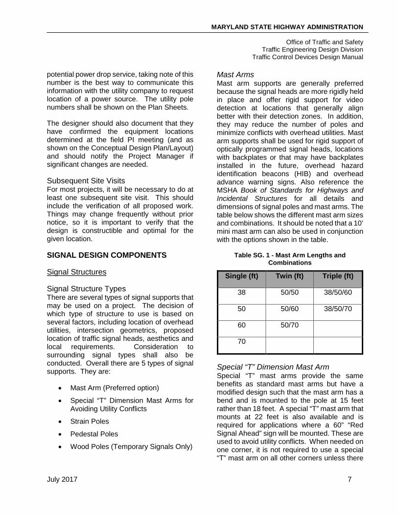
Mast Arms Mast arm supports are generally preferred because the signal heads are more rigidly held in place and offer rigid support for video detection at locations that generally align better with their detection zones. In addition, they may reduce the number of poles and minimize conflicts with overhead utilities. Mast arm supports shall be used for rigid support of optically programmed signal heads, locations with backplates or that may have backplates installed in the future, overhead hazard identification beacons (HIB) and overhead advance warning signs. Also reference the MSHA Book of Standards for Highways and Incidental Structures for all details and dimensions of signal poles and mast arms. The table below shows the different mast arm sizes and combinations. It should be noted that a 10’ mini mast arm can also be used in conjunction with the options shown in the table.
Table SG. 1 - Mast Arm Lengths and Combinations
Single (ft) Twin (ft) Triple (ft)
38 50/50 38/50/60
50 50/60 38/50/70
60 50/70
70
Special “T” Dimension Mast Arm Special “T” mast arms provide the same benefits as standard mast arms but have a modified design such that the mast arm has a bend and is mounted to the pole at 15 feet rather than 18 feet. A special “T” mast arm that mounts at 22 feet is also available and is required for applications where a 60” “Red Signal Ahead” sign will be mounted. These are used to avoid utility conflicts. When needed on one corner, it is not required to use a special “T” mast arm on all other corners unless there

MARYLAND STATE HIGHWAY ADMINISTRATION
Office of Traffic and Safety Traffic Engineering Design Division
Traffic Control Devices Design Manual
July 2017 8
are aesthetic concerns or engineering judgment determines that it would make a better design. Lateral offset of the pole should be checked when using the 15 foot “T” mast
arms so that proper vertical clearance to the adjacent travel lane is provided.
Figure SG. 5- Mast Arm Installation
Figure SG. 6 - Special "T" Dimension Mast Arm Installation

MARYLAND STATE HIGHWAY ADMINISTRATION
Office of Traffic and Safety Traffic Engineering Design Division
Traffic Control Devices Design Manual
July 2017 9
Strain Poles At some locations, strain poles with span wires may be required for proper signal placements. For example, at wide intersections, mast arms may not be long enough to place signal heads in the proper location for optimum visibility. Table SG. 2 - Strain Pole Sizes by Span Length
Span Length Strain Pole Size (O.D. x H.)
< 150 ft 12 in x30 ft
150 ft to 200 ft 12 in x 32 ft (two-ply)
> 200 ft 14 in x 32 ft (two-ply)
Pedestal Poles Pedestal poles are primarily used for mounting pedestrian signal heads, pushbuttons, HIBs, and left-turn signals in the median of divided highways where a breakaway support is desirable. Some other situations when pedestal poles may be used for signal heads include locations where buildings are very close to the road, when overhead utility conflicts exist or for aesthetic purposes in historic areas.
Pedestal poles are generally 5 feet long (for pushbuttons only), 10 feet long (for pedestrian signals), or 14 or 20 feet long for other applications. They can typically support two 16-inch pedestrian signal heads, or a three-section, four-section or five-section vehicular head. All vehicular heads mounted on a 10 feet long pedestal pole must be top mounted and all signal heads mounted on a 20 feet long pedestal pole must be side-mounted. Side mounting on a 10 feet pole is not permitted as the signal will be mounted too low, while top mounting on a 20 foot pole is not permitted as the signal will be mounted too high. When top mounting a five-section head on a 10 or 14 feet long pedestal pole, a modified mounting
bracket is necessary. The 5 foot and 10 foot pedestal poles are preferably installed on a modified base with breakaway couplings due to the small footprint and ease of maintenance and replacement. The 14 and 20 foot pedestal poles are installed on a transformer base. See the latest version of the MSHA Book of Standards for Highway and Incidental Structures for details and dimensions of pedestal poles.
Bridge Mounted Supports Current MSHA policy is that no signals should be mounted on the face of bridges. However, as a last resort, in order to use this application for unique situations, MSHA Bridge Design Division must approve it.
Wood Poles Wood poles are not used for permanent signal design. Wood poles are most commonly used for temporary signals to be included with a Maintenance of Traffic Plan.
Signal Structure Configuration After determining which type of supports will be used for the project, the next step is designing the configuration of the supports. Some examples of typical configurations are shown on the following pages.

MARYLAND STATE HIGHWAY ADMINISTRATION
Office of Traffic and Safety Traffic Engineering Design Division
Traffic Control Devices Design Manual
July 2017 10
Figure SG. 7 - Mast Arm Signal Configuration
*Diagonals are not typically used because they do not provide an ideal signal head to the stop bar distance.

MARYLAND STATE HIGHWAY ADMINISTRATION
Office of Traffic and Safety Traffic Engineering Design Division
Traffic Control Devices Design Manual
July 2017 11
Figure SG. 8 - Span Wire Signal Configurations
*Diagonals are not typically used because they do not provide an ideal signal head to the stop bar distance.
MARYLAND STATE HIGHWAY ADMINISTRATION
Office of Traffic and Safety Traffic Engineering Design Division
Traffic Control Devices Design Manual
July 2017 12
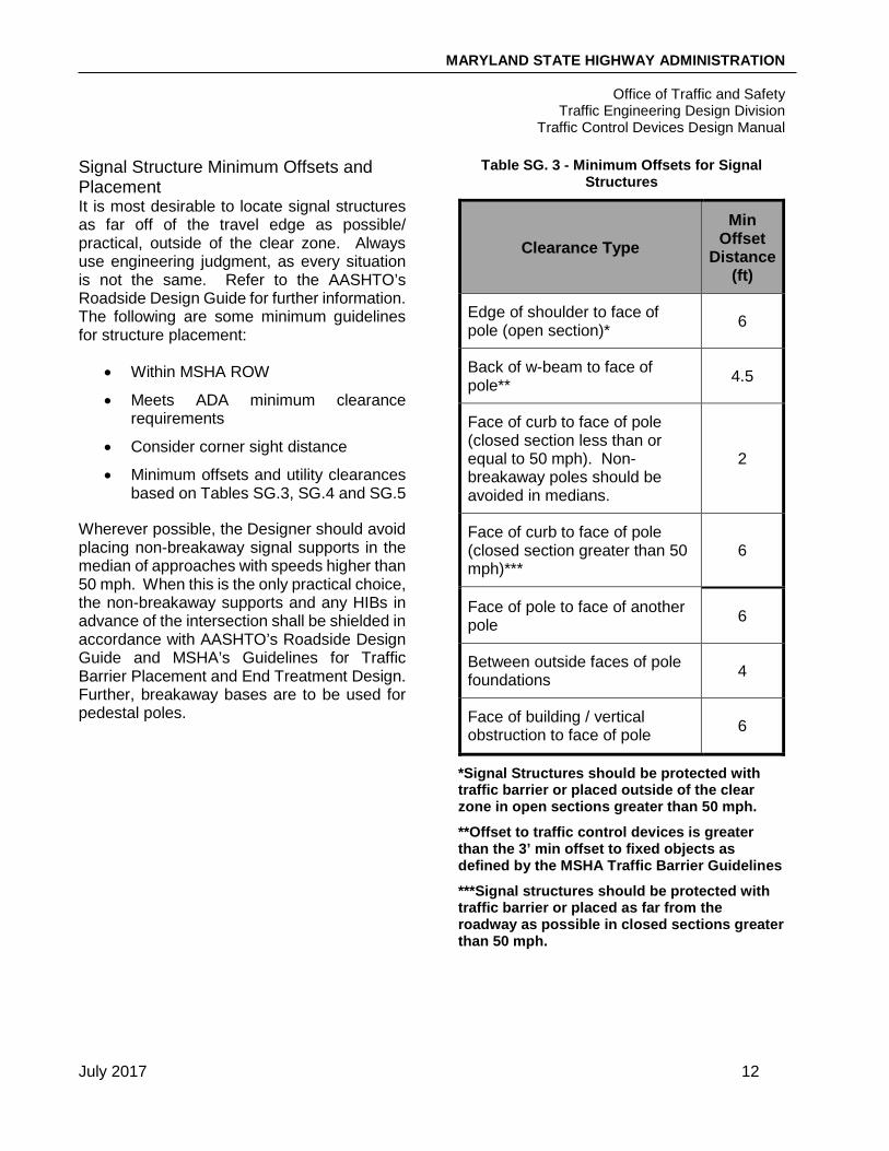
Signal Structure Minimum Offsets and Placement It is most desirable to locate signal structures as far off of the travel edge as possible/ practical, outside of the clear zone. Always use engineering judgment, as every situation is not the same. Refer to the AASHTO’s Roadside Design Guide for further information. The following are some minimum guidelines for structure placement:
• Within MSHA ROW
• Meets ADA minimum clearance requirements
• Consider corner sight distance
• Minimum offsets and utility clearances based on Tables SG.3, SG.4 and SG.5
Wherever possible, the Designer should avoid placing non-breakaway signal supports in the median of approaches with speeds higher than 50 mph. When this is the only practical choice, the non-breakaway supports and any HIBs in advance of the intersection shall be shielded in accordance with AASHTO’s Roadside Design Guide and MSHA’s Guidelines for Traffic Barrier Placement and End Treatment Design. Further, breakaway bases are to be used for pedestal poles.
Table SG. 3 - Minimum Offsets for Signal Structures
Clearance Type Min
Offset Distance
(ft)
Edge of shoulder to face of pole (open section)* 6
Back of w-beam to face of pole** 4.5
Face of curb to face of pole (closed section less than or equal to 50 mph). Non-breakaway poles should be avoided in medians.
2
Face of curb to face of pole (closed section greater than 50 mph)***
6
Face of pole to face of another pole 6
Between outside faces of pole foundations 4
Face of building / vertical obstruction to face of pole 6
*Signal Structures should be protected with traffic barrier or placed outside of the clear zone in open sections greater than 50 mph.
**Offset to traffic control devices is greater than the 3’ min offset to fixed objects as defined by the MSHA Traffic Barrier Guidelines
***Signal structures should be protected with traffic barrier or placed as far from the roadway as possible in closed sections greater than 50 mph.

MARYLAND STATE HIGHWAY ADMINISTRATION
Office of Traffic and Safety Traffic Engineering Design Division
Traffic Control Devices Design Manual
July 2017 13
Utility Clearance Utility clearance is the required distance between utilities such as power, cable, and telephone and signal equipment. The utility clearances also apply to signing and lighting. The utility clearance requirements may have an effect on the configuration of the signal structures and should be looked at from the very beginning.
The clearance distances from utility cables to signal structures and cables must comply with the latest requirements of the MD High Voltage Act, a pole owner (such as BGE) and National Electrical Safety Code (NESC) Sections 233 and 234. The most current version of NESC shall be followed.
Utility clearances apply to both overhead and underground utilities. The typical clearances can be found in the tables below. However, it should be noted that different utility companies may have different rules regarding clearances. Not only may the required clearances differ between companies, but some companies may require certain materials or types of conduit to be used within a certain radius of their utilities. When a structure must be placed close to a utility, the rules should be confirmed with the utility company and hand digging is recommended.
Table SG. 4 - Typical Overhead Utility Clearances
Table SG. 5 - Typical Underground Utility Clearances
Be aware of locations where field spun primary lines are installed, such as in Montgomery County. These are high voltage lines that are installed in the communication space and the 10 feet minimum clearance is still required. During the preliminary design of a signal, if equipment is being installed in close proximity to overhead utilities, it may be beneficial to prepare a utility sketch showing existing utility locations and the required clearances, as shown in Figure SG.9.
Figure SG. 9 - Overhead Utility Locations and
Clearances
Cable Type Horizontal Clearance (ft)
Vertical Clearance (ft)
Communication cables, guys, messengers
2 3
Secondary lines 5 5Primary lines 10 10
Utility Clearance (ft)Gas 5-10Water 5-10Sewer 5-10Electric 3Communications 2Fiber 2Storm Drain 2

MARYLAND STATE HIGHWAY ADMINISTRATION
Office of Traffic and Safety Traffic Engineering Design Division
Traffic Control Devices Design Manual
July 2017 14
When signal equipment is proposed in close proximity to overhead utilities, existing utility heights should be shown on the signal plans. See Figure SG.10 below for an example.
Figure SG. 10 - Plan Sheet Utility Heights
Designers should also consider clearance distances from utility cables to construction equipment when determining signal structure locations. The design must be constructible, however, in some situations the clearances can be met during construction by choosing alternate means and methods of construction. MSHA follows the power line safety regulations specified in Occupational Safety and Health Administration (OSHA) Standard 1926.1408 which contains a table with the required minimum clearance distances for corresponding voltages.
Special Design Considerations
Hazard Identification Beacon (HIB) An HIB is a flashing yellow signal used to indicate a hazard or emphasize a regulation or warning sign. Some examples of HIB’s may include:
• Warning of a signal ahead which does not meet visibility requirements
• Major horizontal or vertical alignment change
• Speed restrictions
• School zones
• Mid-block or advance pedestrian warning
HIBs can operate as either “Active” or “Passive”. Active HIBs are connected to a controller and only flash when activated, such as when the signal is about to change from green to red to warn motorists that there is a “red signal ahead when flashing”. Passive
HIBs flash at all times.
Figure SG. 11 - Active HIB for School Zone
The identification for the need and function of an HIB should be determined during the DR preparation. Since an HIB is a signal, the type of structure, signal heads, detection, cabinet location, utility clearance, etc. should be done during the conceptual design phase. Frequently the HIB is a part of a full signal and is incorporated with the intersection signal. Other times the HIB is an independent element.
Figure SG. 12 - HIB Mounted within Sign Panel

MARYLAND STATE HIGHWAY ADMINISTRATION
Office of Traffic and Safety Traffic Engineering Design Division
Traffic Control Devices Design Manual
July 2017 15
When an HIB is mounted within a sign panel as show in the example above, the signal housing should be flush with the face of sign such that no light can be seen through the attachment. The signal heads should be mounted with brackets and/or straps and an installation detail should be provided on the plans. Special consideration should be given to HIBs that are integrated into a sign when breakaway steel sign supports are used. Flexible tubing/electrical conduit and breakaway couplings should be detailed on the plans to ensure that the power cable to the signal head is protected. As well, a handhole should be provided near the sign supports and signal cable should be spliced with connector kits before running back to the controller cabinet.
Other types of HIBs are used for Emergency Access Signals or Firehouse signals with preemption control as well as “Flag-in-the-air” intersection control devices. “Flag-in-the-air” HIBs provide a highly visible control for stopping vehicular traffic flow at school-entering and crossing points. These are used to compliment the presence of a crossing guard and potentially prevent them from having to stand in the roadway. Operating personnel will have access to a control button that is located inside the controller cabinet which is typically a pole mounted 24” x 24” cabinet.
Intersection Control Beacon (ICB) An ICB is a combination of flashing yellow and red signal heads used to control an intersection. The ICB is used in addition to a stop sign control. The ICB is designed with the same elements as a full signal. Consideration should be given to the design wiring so the ICB may be converted to a full signal. ICBs are typically used in rural areas with lower volumes or in conjunction with Emergency Access Signals.
Flashing ICBs may operate in two modes:
• Yellow for major street and red for all other approaches or streets
• Red for all approaches
Signal Heads
Number of Signal Heads A minimum of two signal heads shall be provided for each movement, including exclusive and exclusive/permissive left turns, to maintain visibility and ensure redundancy of the signal head display. Only one far side head is required for right turn overlaps; a near side head is only required if poor sight distance is present. A third signal head may be placed at multi-lane signalized intersections where:
• The mainline prevailing travel speed (85th percentile) is 45 mph or higher.
OR
• Engineering judgment determines that it is necessary to eliminate poor situations such as unusual highway geometrics, the surrounding area, line of sight and driver expectancy (for locations where the speed is less than 45 mph).
Additional guidance can be found in MSHA’s “Guideline for Placement of a Third Signal Indication” and the MdMUTCD.
Size of Signal Heads Twelve-inch signal heads shall be used for all Traffic Control Device applications. Eight-inch signal heads are no longer used and any existing eight-inch signal heads should be upgraded during any signal upgrade project. In any situations where engineering judgment indicates that an eight-inch signal head may be preferred (emergency vehicle signals, Flag-In-The-Air (FITAs), pedestrian activated signals, bicycle signals, etc.), a waiver approved by the Director must be obtained prior to plan approval.

MARYLAND STATE HIGHWAY ADMINISTRATION
Office of Traffic and Safety Traffic Engineering Design Division
Traffic Control Devices Design Manual
July 2017 16
Signal Head Sections / Arrangements The most commonly used configuration for signal heads is a simple 3 section head with the “ball” display. Another option is the use of arrow displays.
There are several typical signal head arrangements as follows:
• Three section head with circular indications (twelve-inch): Permissive phasing and the second head for most other phasing such as exclusive/permissive and split phasing (to complement the 4 or 5 section head required).
• Five section cluster head (all twelve-inch): Signal head for exclusive/ permissive phasing (left arrows) and right-turn overlap (right arrows).
• Five section vertical head: Far-left turn signal head for exclusive/permissive phasing; this signal head can be used but is not the preferred option. The doghouse five section head is preferred. If this vertical five section head his used, it shall be side mounted on a 20 foot pedestal pole or installed on a shorter pedestal pole with a modified bracket due to its tendency to break under wind loading when attached on top of a pedestal pole with a typical bracket.
• Three section head with arrow indications: Exclusive phasing and flashing red arrow exclusive/permissive operation.
• Four section vertical head: Split-phasing.
Figure SG.13 shows diagrams of the different signal head configurations and sizes used for MSHA traffic control signals.
All projects shall require the installation of black-faced, LED signal heads unless otherwise specified.
For locations where crash data indicates that glare was a cause of crashes, the use of backplates, such as the ones shown in the figure below, may be considered. However, use of backplates should be limited and should primarily take place on roadways running in east-west directions. The installation of backplates must be approved by the Director. Backplates should not be installed on any signal structures that are older than 25 years. If a signal structure is 25 years old or less, they must be thoroughly inspected by the Administration to determine whether backplates may be installed.
Figure SG. 13 - Signal Head Arrangements

MARYLAND STATE HIGHWAY ADMINISTRATION
Office of Traffic and Safety Traffic Engineering Design Division
Traffic Control Devices Design Manual
July 2017 17
Figure SG. 14 - Signal Backplates
Signal Head Placement The bottom of the traffic signal head housing (including backplates when applicable) on overhead signals should be at least 17 feet and not more than 19 feet above the high point of the roadway.
The horizontal placement may vary with the type of display on the approach. The primary concern when placing signal heads is visibility. Refer to the Traffic Control Signal Features section in the MdMUTCD for a complete discussion of this topic. A table in this section of the MdMUTCD provides minimum visibility distances for signal heads. The Designer should check the roadway horizontal alignment, vertical alignment on approaching roadways and any potential obstructions, such as buildings, walls, etc. when selecting the proper placement for traffic signal indications.
The MdMUTCD lists several criteria that should be considered when locating signal heads. Some of these guidelines that will determine the placement of the signal heads are as follows:
• A minimum of two signal heads shall be provided for each phase at an intersection.
• At least one, and preferably both, of the signal heads shall be placed within 20 degrees to the right or left of the center of
the approach lanes for the through movement.
• At least one, and preferably both, of the signal heads should be placed between 40’ and 120’ from the stop line.
• A near-side signal head should be provided when the distance from the stop line to one or more far-side signal heads is more than 120’.
• A near-side signal head should be provided when there are unusual roadway geometrics, 3 or more through lanes, or when the horizontal or vertical alignment of the roadway limits the minimum visibility distance requirements.
• An exclusive movement, with a double left turn lane, shall have two far-side signal heads. A supplemental near-side signal head or far left signal head shall also be used.
• An exclusive or exclusive/permissive left-turn movement, with a single turn lane, requires a near-side and far-side signal head.
• A side street split phase requires a near-side signal.
• Far Left Turn Traffic Signals are generally used when the geometry of an intersection restricts view of far and/or near-side signal heads. This indication is in addition to the required number of signal indications as specified in the MdMUTCD and TEDD standards, and may eliminate the near-side exclusive/permissive and/or exclusive signal head.
If the minimum visibility requirements according to MdMUTCD Table Minimum Sight Distance for Signal Visibility (85th percentile) cannot be met, a Signal Ahead (symbol) sign and/or a hazard identification beacon shall be installed.

MARYLAND STATE HIGHWAY ADMINISTRATION
Office of Traffic and Safety Traffic Engineering Design Division
Traffic Control Devices Design Manual
July 2017 18
Figure SG. 15 - Signal Head Horizontal Placement – Preferred for two far side and one
near side three-section standard heads
Figure SG. 16 - Signal Head Horizontal Placement – Typical Signal Head Placements
for Exclusive/Permissive Left Turn
Figure SG. 17 - Preferred near and far side three section heads with arrows and two three-
section standard heads
Figure SG. 18 - Typical Far Left Turn Traffic
Signal Head Location*
*This configuration with diagonal should be used only when no other layouts are feasible
MARYLAND STATE HIGHWAY ADMINISTRATION
Office of Traffic and Safety Traffic Engineering Design Division
Traffic Control Devices Design Manual
July 2017 19
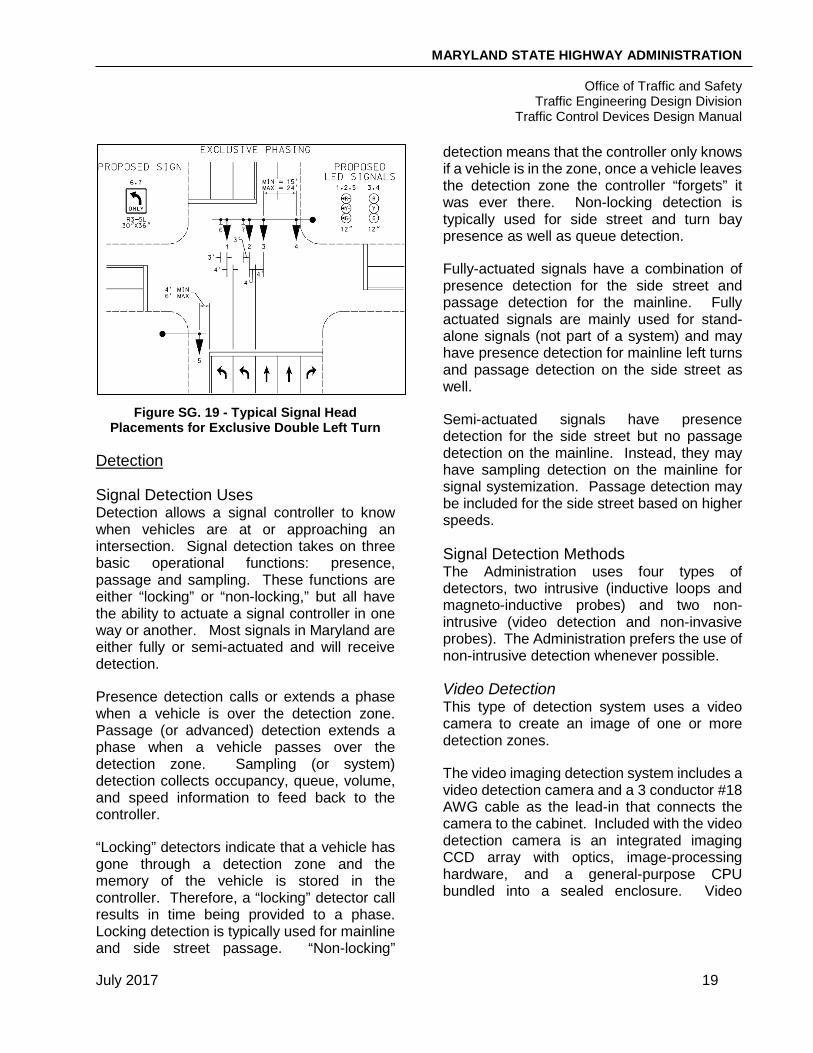
Figure SG. 19 - Typical Signal Head
Placements for Exclusive Double Left Turn
Detection
Signal Detection Uses Detection allows a signal controller to know when vehicles are at or approaching an intersection. Signal detection takes on three basic operational functions: presence, passage and sampling. These functions are either “locking” or “non-locking,” but all have the ability to actuate a signal controller in one way or another. Most signals in Maryland are either fully or semi-actuated and will receive detection.
Presence detection calls or extends a phase when a vehicle is over the detection zone. Passage (or advanced) detection extends a phase when a vehicle passes over the detection zone. Sampling (or system) detection collects occupancy, queue, volume, and speed information to feed back to the controller.
“Locking” detectors indicate that a vehicle has gone through a detection zone and the memory of the vehicle is stored in the controller. Therefore, a “locking” detector call results in time being provided to a phase. Locking detection is typically used for mainline and side street passage. “Non-locking”
detection means that the controller only knows if a vehicle is in the zone, once a vehicle leaves the detection zone the controller “forgets” it was ever there. Non-locking detection is typically used for side street and turn bay presence as well as queue detection.
Fully-actuated signals have a combination of presence detection for the side street and passage detection for the mainline. Fully actuated signals are mainly used for stand-alone signals (not part of a system) and may have presence detection for mainline left turns and passage detection on the side street as well.
Semi-actuated signals have presence detection for the side street but no passage detection on the mainline. Instead, they may have sampling detection on the mainline for signal systemization. Passage detection may be included for the side street based on higher speeds.
Signal Detection Methods The Administration uses four types of detectors, two intrusive (inductive loops and magneto-inductive probes) and two non-intrusive (video detection and non-invasive probes). The Administration prefers the use of non-intrusive detection whenever possible.
Video Detection This type of detection system uses a video camera to create an image of one or more detection zones.
The video imaging detection system includes a video detection camera and a 3 conductor #18 AWG cable as the lead-in that connects the camera to the cabinet. Included with the video detection camera is an integrated imaging CCD array with optics, image-processing hardware, and a general-purpose CPU bundled into a sealed enclosure. Video

MARYLAND STATE HIGHWAY ADMINISTRATION
Office of Traffic and Safety Traffic Engineering Design Division
Traffic Control Devices Design Manual
July 2017 20
detection should make use of the latest equipment approved by the MSHA Signal Shop.
When adding a new video detection camera at a location with existing video detection, the entire video detection system should be replaced, including the video interface equipment, if the existing detectors do not meet current standards. The compatibility of the new system should be verified before installation. The preferred camera for MSHA usage changes periodically, so it is important to verify that the latest approved equipment is used.
Figure SG. 21 - Rack Mounted Video Interface Card
Figure SG. 22 - Video Interface Panel
For maximum performance, the Administration recommends attaching the video camera to a mast arm on the far side of the intersection centered above the lane of the detection zone. It may also be installed on a lighting bracket arm or video detection camera arm attached to the signal pole. An extension pole can be used to mount the camera an additional 5 feet above the mast arm in order to increase the field of view but prior approval from TEDD is needed before this is utilized. For every foot of sensor height, the camera can “see” about 10 feet. For locations with traffic signals on span wire, the video camera should be located to the left of the left-turn lane mounted on the signal pole. If possible, cameras should not be located to the right of the lane (this is to avoid detecting larger vehicles in adjacent lanes).
Camera location and mounting height are dependent on the geometry of the intersection and obtaining an unobstructed field of view. Video detection is not effective if poles are set back significantly from the roadway. Based on the location and distance of the camera from the desired detection area, the Field of View (FOV) can be calculated and the required lens can be determined. It should be noted that a single camera can be used for detection at both a left turn stop line and for system/sampling detection (other direction of travel) if the median is not very wide.
Video Interface Card
Figure SG. 20 - Video Interface Card (Close Up)
MARYLAND STATE HIGHWAY ADMINISTRATION
Office of Traffic and Safety Traffic Engineering Design Division
Traffic Control Devices Design Manual
July 2017 21
Where significant truck volumes are present, video detection cameras should be installed as high as possible to better aim the camera at the stop line. This will help reduce trucks from “lagging” in the detection zone and will avoid “sluggish” signal timing. It has been observed that video detection zones are being programmed to be much larger than your traditional in-pavement loop zone, so placement of the camera is extremely important. Signal technicians should find a balance between the size of video detection zones and allowable phase extension time when programming the controllers.
Some additional considerations in designing video detection are:
• Lighting brackets
• Obstructions such as overhead utilities, billboards, traffic signals, etc.
• Occlusion of the detection area by moving vehicles, both downlane and crosslane
• Shadow effects/horizon should not be visible in the field of view of camera
• Distance from camera to detection zone
• Select a location that minimizes vibration and motion
• Part time signals (school signal)
Magneto-inductive Vehicle Sensor Magneto-inductive vehicle sensors are commonly known as microloop probes. A microloop probe is a small cylindrical, passive transducer, which transforms the earth’s vertical magnetic field intensity into inductance. It transforms changes in magnetic field intensity into inductance changes that can be sensed by detector units. The microloop probes have the same application and placement as a 6’X6’ small area inductive loop. However, a microloop probe acts more like a
point detector and provides very good resistance to detecting vehicles in adjacent lanes.
Non-invasive microloop probes are installed in a seamless conduit under the roadway with handholes on each side of the road. The handholes for this type of probe are installed with the long dimension perpendicular to the edge of road to ease installation. The handhole symbol must be shown on the plans in that orientation.
This type of detection is not in the pavement and will not be affected with roadway milling. It is also ideal for high-speed / high-volume traffic conditions since it results in less traffic disruptions and conflicts during installation. Where resurfacing is anticipated in the near future and where lane patterns will shift, the probes can be slid horizontally as lane patterns change. Further, in the event they go bad, damaged probes can be pulled out and replaced with new ones in the same conduit.
The non-invasive microloop probe lead-in runs continuously from the probe devices to the controller. It is available in any length up to 1,000 feet.
Specific MSHA practice includes the following guidelines:
• Three probes per lane at 3’ centers.
• Inserted into a three-inch non-ferrous Schedule 80 conduit.
• Conduit is installed 21 +/- 3 inches below the road surface using horizontal directional boring.
• Install one handhole on each side of the road perpendicular to the roadway (the short side of the handhole shall be parallel to the roadway).
MARYLAND STATE HIGHWAY ADMINISTRATION
Office of Traffic and Safety Traffic Engineering Design Division
Traffic Control Devices Design Manual
July 2017 22
Another method of installing microloop probes beneath the roadway surface is by drilling a 1-inch diameter hole (18-inch to 24-inch deep) in the pavement and inserting the probes. This method also has a greater service life over 6 feet x 6 feet inductive loops due to the reduced exposure to hazards such as road traffic, pavement movement, pavement deterioration, and roadwork but do not offer the same repair efficiency as the non-invasive microloop probes.
Microloop probes are not used in concrete pavements, in tunnels, around power lines or rail lines, or on existing bridge decks.
When installing microloop probes, a magnetic field analysis should be conducted prior to commencing boring and cutting of pavement. Refer to the MSHA Book of Standards for Highways and Incidental Structures for additional specific installation guidelines.
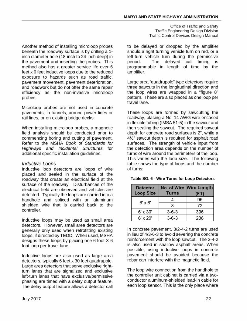
Inductive Loops Inductive loop detectors are loops of wire placed and sealed in the surface of the roadway that create an electrical field at the surface of the roadway. Disturbances of the electrical field are observed and vehicles are detected. Typically the loops are carried into a handhole and spliced with an aluminum shielded wire that is carried back to the controller.
Inductive loops may be used as small area detectors. However, small area detectors are generally only used when retrofitting existing loops, if directed by TEDD. When used, MSHA designs these loops by placing one 6 foot X 6 foot loop per travel lane.
Inductive loops are also used as large area detectors, typically 6 feet x 30 feet quadrupole. Large area detectors that serve exclusive right-turn lanes that are signalized and exclusive left-turn lanes that have exclusive/permissive phasing are timed with a delay output feature. The delay output feature allows a detector call
to be delayed or dropped by the amplifier should a right turning vehicle turn on red, or a left-turn vehicle turn during the permissive period. The delayed call timing is programmable in length of time by the amplifier.
Large area “quadrupole” type detectors require three sawcuts in the longitudinal direction and the loop wires are wrapped in a “figure 8” pattern. These are also placed as one loop per travel lane.
These loops are formed by sawcutting the roadway, placing a No. 14 AWG wire encased in flexible tubing (IMSA 51-5) in the sawcut and then sealing the sawcut. The required sawcut depth for concrete road surfaces is 2”, while a 4½” sawcut depth is required for asphalt road surfaces. The strength of vehicle input from the detection area depends on the number of turns of wire around the perimeters of the loop. This varies with the loop size. The following table shows the type of loops and the number of turns:
Table SG. 6 - Wire Turns for Loop Detectors
In concrete pavement, 3/2-4-2 turns are used in lieu of 4/3-6-3 to avoid severing the concrete reinforcement with the loop sawcut. The 2-4-2 is also used in shallow asphalt areas. When possible, using inductive loops in concrete pavement should be avoided because the rebar can interfere with the magnetic field.
The loop wire connection from the handhole to the controller unit cabinet is carried via a two-conductor aluminum-shielded lead-in cable for each loop sensor. This is the only place where

MARYLAND STATE HIGHWAY ADMINISTRATION
Office of Traffic and Safety Traffic Engineering Design Division
Traffic Control Devices Design Manual
July 2017 23
a splice is allowed for signal cable except for ground mounted HIBs as discussed above. As such, the lead-in cable must be a continuous run of wires from the handhole adjacent to the loop location to the controller cabinet, as the splicing of lead-in wires is not allowed and a break in the loop run will cause the loop to fail. To ensure that the wire is protected from cracks in the roadway, all new loop wires should be placed in a 1” conduit from the travel way to the nearest handhole as described in the ‘Conduit – General Uses’ section herein.
Some additional considerations when designing loop detectors:
• Avoid surface features (drainage, manholes, gas valves, etc.)
• Avoid installing in deteriorated pavement (susceptible to failure)
• Avoid long lead-in cables (susceptible to failure)
Other Technologies In addition to video imaging, inductive loops and microloop probes, several other technologies are available for signal detection. Although they are not regularly used within the state of Maryland, some of these technologies include:
• Microwave
• Magnetic
• Magnetometer
• Infrared
• Light Emission
• Sonic
• Radar
These are not typically used on MSHA projects unless special situations arise.
Types and Placement of Signal Detection
Presence Detection Presence detection indicates that a vehicle is in the detection zone. Presence detection can be either “locking” or “non-locking” depending on the application. These detectors are typically used on side streets and left turn bays at the stop line when it is critical to know if a vehicle is waiting for green. It is important to add new presence detection in the appropriate (turn) lane when a permissive signal phase is replaced with an exclusive/permissive or exclusive signal phase. The preferred presence detection is video imaging detection; however, 6 feet x 30 feet inductive loops are common at existing signals, especially at span signals. Another use of presence detection is for queue detection. Due to the distance back from the signal, 6 feet x 20 feet inductive loops are typically used.
Location of Presence Detection For presence detection, video detection cameras are generally placed on the far side of an intersection on the mast arm or a lighting bracket arm angled at the stop line of the movement being served. Ideally, the detection zones should be placed parallel to the lanes of traffic for optimal presence detection accuracy of moving or stopped vehicles. One camera is typically required for each approach for presence detection.
Figure SG. 23 - Typical Video Detection
Location (Mast Arm Mount)

MARYLAND STATE HIGHWAY ADMINISTRATION
Office of Traffic and Safety Traffic Engineering Design Division
Traffic Control Devices Design Manual
July 2017 24
Figure SG. 24 - Typical Video Detection
Location (Lighting Arm Mount)
Figure SG. 25 - Typical Video Detection Location (Extension Arm Mount)
When used, a 6’x30’ inductive loop is installed at or near the stop line, commonly 12” behind the stop line. There are instances though when it may be deemed necessary to locate it in front of the stop line to account for cars that stop in front of the stop line. For installation of a 6’x20’ inductive loop for queue detection, an Engineering study is needed to determine the appropriate set back from the signal. Figure SG.26 shows an example of detection locations at an intersection.
Passage Detection Passage detection, also called point or pulse detection, identifies when a vehicle has passed through a detection zone and sends a message to the controller. Passage detection has a setting of “locking” in the controller and extends the green time for that movement.
These detectors are typically used on mainlines. The preferred passage detection is non-invasive microloop probes. In areas that right-of-way, geometrics, or underground utilities restrict the use of non-invasive probes, microloop probes would be the next choice for passage detection. Another option is to use 6 feet x 6 feet inductive loop detectors or video imaging cameras for passage detection. When video imaging is used for passage detection, it is typically for side streets.
Location of Passage Detection Passage detection is placed in relation to the stop line, based on the posted speed and a passage time of 5 seconds for the mainline. For side road passage detection, if the speed limit is 25mph or less no passage detection is used. For 30-40mph, a passage detector is placed 90’ in advance of the stop line. For 45mph and above, a 3 second passage time is used for the placement of detection. Note: if both approaches have the same approach speed, a passage time of 5 seconds should be used for both approaches. Further, private entrances do not receive any passage detection. If passage detection cannot be physically installed at the designated setback distance due to utilities, entrances, etc., the preferred method is to move the detectors slightly further away from the signal rather than closer. However, if there are physical constraints requiring the detectors to be moved significantly further away from the signal, the option of moving them slightly closer to the signal may be considered. See Tables SG. 7 and SG.8 for detector setback information.

MARYLAND STATE HIGHWAY ADMINISTRATION
Office of Traffic and Safety Traffic Engineering Design Division
Traffic Control Devices Design Manual
July 2017 25
Figure SG. 26 - Detection Zone Types
Table SG. 7 - Detector Setback for Side Streets
Posted Approach Speed (mph)
Detector Setback Criteria
0-25 No Detection
30-40 90 feet
*45+ 3 sec. Passage Time
Private Entrance No Detection *Side streets with the same approach speed as mainline should have a 5 second passage time
Table SG. 8 Detector Setback from Stop Line, in Feet
Posted Speed (mph)
Passage Time from Detector to Stop Line (sec)
1 2 3 4 5 20 29 58 87 116 145 25 36 78 108 144 180 30 44 88 132 176 220 35 51 102 153 204 255 40 59 118 177 236 295 45 66 132 198 264 330 50 73 146 219 292 365 55 81 162 243 324 405 60 88 176 264 352 440 65 95 190 285 380 475

MARYLAND STATE HIGHWAY ADMINISTRATION
Office of Traffic and Safety Traffic Engineering Design Division
Traffic Control Devices Design Manual
July 2017 26
Sampling Detection The term “system loops” or “sampling detectors” refers to detection feeding information about a signal system back to the controller. The operation of system and sampling detection only uses passage detectors. This detection collects data such as occupancy, queues, volumes and speeds, and sends it back to the controller.
Sampling detection should be installed when entering a system and at major intersections as recommended by TDSD.
Video detection is typically used for new or replacement sampling detection. However, 6 feet x 6 feet inductive loops provide more accurate presence and occupancy readings and are still used in some jurisdictions.
Location of Sampling Detection Sampling detection shall be placed downstream of an intersection in a location that represents free flow of traffic.
The placement of the system detection is designed differently than the placement of the individual intersection detection. The specific location of system detectors depends on the traffic patterns, direction of traffic, distribution of traffic, and location of heavily traveled intersections within the arterial system. The goal is to locate the detectors to collect data that is representative of the major traffic flow in the system. In most cases, system detectors are placed on the upstream and downstream ends of the arterial. One system detector per lane shall be installed.
Pedestrian Amenities
Pedestrian Crossings Pedestrians play a critical role in signal design. During the conceptual phase, it should be determined if a pedestrian signal will be designed. Pedestrian Signals shall be stated in the DR and shall be installed per the following criteria:
• All crossings with medians regardless of width
• All crossings of 4 or more lanes
• Crossing width of 30 or more feet
• Wherever the ADE-T’s determine such use is justified based upon factors such as: elderly pedestrians, school children, and unusual intersection geometrics.
If pedestrian phasing is included, then the inclusion of crosswalks, ramps compatible to ADA standards, pedestrian signals and poles shall be considered during the conceptual design. Crosswalks can be installed without pedestrian signals but pedestrian signals cannot be installed without crosswalks. All new pedestrian crossings shall be designed for either the present or future installation of accessible pedestrian signals (APS).
Countdown Pedestrian Signals (CPS) All signalized pedestrian crossings shall have 16 inch LED countdown pedestrian signals, unless otherwise specified in the D.R. An example of a countdown pedestrian signal is shown below. Countdown pedestrian signals should be installed a maximum of 10’ laterally offset from the crosswalk extended to ensure good visibility.
Figure SG. 27 - Countdown Pedestrian Signal

MARYLAND STATE HIGHWAY ADMINISTRATION
Office of Traffic and Safety Traffic Engineering Design Division
Traffic Control Devices Design Manual
July 2017 27
Note that when emergency vehicle preemption is present at the signalized intersection, the use of countdown pedestrian signals should be evaluated and reviewed prior to design. This is to prevent pedestrians from receiving a false impression that they have more time to cross the street than the signal allows once a preemption call is placed to the controller. When countdown pedestrian signals are used at signals with preemption, they are programmed such that the pedestrian clearance cannot be shortened.
Accessible Pedestrian Signals (APS) An APS is a device that communicates information to a pedestrian about pedestrian timing in non-visual formats such as audible tones, verbal messages, and/or vibrating surfaces. This also includes detectable warning surfaces or truncated domes. During conceptual design it is necessary to identify the potential demand and/or request for accessible pedestrian signals. In the MSHA OHD Accessibility Policy & Guidelines for Pedestrian Facilities along State Highways, it states that “All projects, regardless of who is administering the contract, shall accommodate and provide accessibility for persons with disabilities where it is reasonable, feasible and appropriate to do so…..basically any time we do anything to the roadway that would or could improve pedestrian access.” Further, ADA ramps shall be provided in accordance to the functionality and requirements of the APS.
APS can provide information to pedestrians about the existence and location of the pushbutton, beginning of the walk interval, direction of the crosswalk and location of the destination curb, intersection street names in Braille or with a speech message, intersection signalization with a speech message and intersection geometry through maps, diagrams, or speech messages.
APS stations include a tactile arrow and pushbutton attached to an informational sign with the intersection street name to be crossed
in Braille. This station has capabilities of providing a vibrotactile walk indication (in addition to audible walk indication), a pushbutton locator tone, and automatic volume adjustment. A pedestrian education sign shall be mounted above the APS station that also includes the name of the street being crossed. This street name should be shown in the Construction details on the plan pertaining to the sign installation.
If the major street minimum green interval is sufficient for the required side street (WALK and flashing DON’T WALK/Countdown) pedestrian intervals, the APS pushbutton generally serves only to provide audible notice of when crossing is permitted rather than to trigger a pedestrian cycle. The pedestrian signal will automatically go to WALK every cycle but the audible/tactile message will not be activated unless the button is pushed. However, the pedestrian signals for crossing the mainline are generally alternate pedestrian phases which are pushbutton actuated, which means the button must be pressed in order to receive a WALK phase and audible/tactile message. This should be clarified on the General Information sheet under the ‘Intersection Operation’ section and reflected in the Phasing Diagram on the signal plan sheet.
Signal plans that include APS should contain verbal messages shown on the General Information sheet under the ‘Special Notes’ section. A typical verbal message is “Wait to cross Main at First. Wait.” Note that the roadway designation of “street, road, avenue, etc.” should not be included in the message. If an intersection contains a road that has two different names on two legs of the intersection or if an intersection contains a road on one leg and a ramp to a highway, freeway, or expressway on the opposite leg, both names should be included in the verbal messages. See the example below and the corresponding verbal messages.

MARYLAND STATE HIGHWAY ADMINISTRATION
Office of Traffic and Safety Traffic Engineering Design Division
Traffic Control Devices Design Manual
July 2017 28
Figure SG. 28 - APS Message Sample
Intersection
The messages would be as follows:
• To cross the North Leg: “Wait to cross Schley at Rosemont. Wait.”
• To cross the South Leg: “Wait to cross US 15 Ramp at Rosemont. Wait.”
• To cross the East Leg and West Leg: “Wait to cross Rosemont at Schley and US 15 Ramp. Wait.”
If, despite design efforts, the crosswalk is slanted and shifts 10 feet or more laterally, then the following message should be added at the end of the crossing messages above, “Crosswalk angles right” or “left” depending on the situation.
APS pushbutton stations should typically be located based on the following guidelines. Designs that deviate from these guidelines require an APS waiver. Note that specified dimensions for pushbutton placement refer to the actual face of the button not center of pole.
• Adjacent to a level all-weather surface to provide access from a wheelchair,
• On a wheelchair accessible route to the curb ramp
• Within 5 Ft (60 in) of the crosswalk line extended
• Maximum 10 Ft (120 in) and minimum 2.5 Ft (30 in) from the edge of the curb, shoulder, or pavement
• At least 10 Ft (120 in) from other APS pushbuttons located on the same corner
• Maximum 18 in reach to pushbutton from a 5’ x 5’ level landing area (preferred)
• From level landing area, height should be no more or less than 36”
• Tactile arrows on pushbuttons should be oriented parallel to the associated crosswalk and should have high visual contrast
• Pedestrian symbol on pushbutton to face crosswalk
Figure SG. 29 - APS Station and Pedestrian Education Sign (For
Countdown Signals)

MARYLAND STATE HIGHWAY ADMINISTRATION
Office of Traffic and Safety Traffic Engineering Design Division
Traffic Control Devices Design Manual
July 2017 29
• Minimum of 32” clearance (need ADA Waiver), 60” minimum preferred (without waiver)
• Pushbutton orientation shall face toward the intersection on the outside of the crosswalk.
An example of an acceptable placement of Accessible Pedestrian Signals can be seen in the Figures SG.30.
Alternatives to the above design criteria are available for the addition of APS to an existing intersection with existing pedestrian signals. When two pushbuttons must be installed on the same pole, speech walk messages and pushbutton information messages are needed. An APS waiver approved by the Director is required for this design.
Figure SG. 30 - Acceptable Placement of APS
Figure SG. 31 - Acceptable Placement of APS
MARYLAND STATE HIGHWAY ADMINISTRATION
Office of Traffic and Safety Traffic Engineering Design Division
Traffic Control Devices Design Manual
July 2017 30
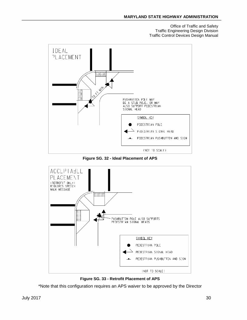
Figure SG. 32 - Ideal Placement of APS
Figure SG. 33 - Retrofit Placement of APS
*Note that this configuration requires an APS waiver to be approved by the Director

MARYLAND STATE HIGHWAY ADMINISTRATION
Office of Traffic and Safety Traffic Engineering Design Division
Traffic Control Devices Design Manual
July 2017 31
ADA Requirements The general ADA requirements for ramps, sidewalks and median cut-throughs can be found in the MSHA Book of Standards and the OHD Guidelines. However, it is important to recognize a few basic parameters to consider when designing for pedestrian crossings and APS devices. When ADA features are included in the design, blow-up details showing pertinent ramp, sidewalk and equipment locations and dimensions should be provided on the signal plan if space permits or more often as a separate detail sheet.
For sidewalk ramps, the maximum running slope is 12:1 (~8%) and must include or be adjacent to a flat landing area with maximum slope 48:1 (~2%). The preferred design for crosswalks is to have separate ramps for each crossing with a reasonable separation on each corner of an intersection. For locations where two crosswalks converge at a combination ramp (only 1 ramp is provided on the corner), there should be a 48” minimum clear space between the two crosswalks to ensure the detectable warning surface is within the crosswalk boundaries, as shown in the figure below.
Figure SG. 34 - Crosswalks with Shared Ramp
Sidewalks should be 60” wide, not including the top of curb. Maximum cross slope is 48:1 (~2%). Minimum width at isolated pinch points is 32”, with max length 24” and will require ADA Waiver.
Median cut-through should be 60” minimum in length and 48” minimum in width. If it is less, the median nose should be pulled back to accommodate a full crosswalk. If the median cut-through is raised, the flat area should be 48” x 48” minimum. Crosswalk should be straight and not kinked at the median if possible. Pushbuttons in the median depend on the length of crossing, signal phasing, number of pedestrians width of median, and location specific considerations. Pushbuttons are particularly important for crossings that are part of an alternate pedestrian phase in which the crossing phases are only initiated by pressing a button. The list below contains guidelines indicating when pushbuttons are warranted in medians:
• Median width is greater than or equal to 10’ • Mainline width is 33’ or greater on one side
of the median • Mainline speeds are greater than or equal
to 35 mph • Two pushbuttons should be installed in the
median when the width is greater than or equal to 20’
• Pedestrian accident history (particularly 3 or more in 5 years) may warrant median pushbuttons in locations not meeting the criteria above
• Median pushbuttons are NOT to be used for pedestrian phases which are on recall (typically 2 and 6)
The guidelines above are meant to aid designers. However, based on engineering judgement, design request, and district input about actual pedestrian volume and behavior at specific sites, design variations are possible.

MARYLAND STATE HIGHWAY ADMINISTRATION
Office of Traffic and Safety Traffic Engineering Design Division
Traffic Control Devices Design Manual
July 2017 32
Design Waivers If the aforementioned design criteria cannot be met nor proper APS placement based on the ADA guidelines and MSHA Book of Standards, then a design waiver must be submitted. There are two types of waivers: ADA and APS. If ADA guidelines cannot be met, such as the lack of a 5 foot flat landing area, then an ADA waiver should be submitted to OHD for approval. If APS requirements cannot be met, such as placing a pushbutton more than 10 feet from the edge of curb, then an APS waiver should be submitted to the Director of OOTS for approval. A project should not be awarded to Construction until all necessary approved waivers have been received.
Signal Preemption Signal preemption is used to implement a special sequence or phase of signal indications by responding to an external command. Some of these applications include a firehouse, emergency vehicles, railroad crossings, and transit signal priority. The most common application in Maryland is for firehouse preemption.
When or if signal preemption is required should be determined in the conceptual design. This shall be included on the Design Request. The type of preemption to be used should also be determined. Firehouse preemption is usually designed with hardwiring or the use of an optically activated priority control.
A general rule of thumb is that a pushbutton and hard-wire should be used if the firehouse is within 800’ from the intersection, but coordination with the firehouse chief is needed on actuation method. Consideration should also be given to measures to clear queues on the mainline for emergency vehicles access.
Transit signal priority (TSP) is an operational strategy that is applied to reduce the delay transit vehicles experience at traffic signals. TSP involves communication between transit
vehicles and signals. The reduction of delays is accomplished through extending greens, truncating reds, altering phase sequences, and including special phases. TSP typically does not interrupt coordination. TSP is initiated using an infrared detector eye and a GPS detector.
Optically Activated Priority Control System An optically activated priority control system is a system with an emitter and detector used for preemption. The emergency vehicle has an emitter mounted to it that produces pulses of high intensity light that is received by a detector located at the signal. The detector is usually located on top of a signal mast arm. After the detector receives the emission, the message is sent back to the controller and the signal is preempted. This option is good for clear lines of visibility when the emergency vehicles travel a straight path to the signal. The optimal line of sight is 1,500 feet. This eliminates the need for extensive wiring to a firehouse.
Receivers should also be installed at other adjacent signals along the corridor, as well as key intersections within targeted areas to aid in vehicular progression during an emergency.
Hard Wire Hard wiring is running a direct wire from the signal controller directly into the firehouse. The firehouse is equipped with a pushbutton that is used when signal preemption is needed. This option is good when the firehouse is in close proximity to the signal and visibility may be limited. This is also the common application for rail preemption. Right-of-Way and the potential requirement of easements must be considered for hard wiring firehouse preemption.
Phasing for Preemption Signal phasing is generally set up one of two different ways for preemption depending on where the signal is located. For most cases, when the signal at or near a fire station is
MARYLAND STATE HIGHWAY ADMINISTRATION
Office of Traffic and Safety Traffic Engineering Design Division
Traffic Control Devices Design Manual
July 2017 33
preempted, the signal will cycle to an all red phase for traffic. Thus, emergency vehicles will be able to leave the station without conflict. The other typical scenario is for signals that are on the same corridor as the fire station. These signals will be preempted such that the mainline (or roadway of which the emergency vehicle will travel) will be phased to green so that cars are flushed through the corridor and the emergency vehicle will not experience delays.
Wiring and Grounding Once the structures, signal heads and detectors are in place, then the wiring design may begin. The electrical wiring is a key element to proper operation of the signal. The wiring is represented on the wiring diagram included on the general information sheet.
Detectors Video imaging cameras are wired using a 3 conductor #18 AWG cable that runs from the video detection camera to the controller. This cable is measured by linear feet and no longer comes in pre-manufactured lengths like previous models. The current MSHA approved equipment should be used and the contract items should be verified as the cable may be incidental.
Microloop probes are wired with a continuous run from the probe through the handhole back to the cabinet using a specific cable for the probe. (This is a 4 conductor No. 18 AWG shielded cable with a polyethylene jacket).
Inductive loop wires are formed using a No. 14 AWG wire incased in flexible tubing that is carried to the nearest handhole. From this point, a 2-conductor aluminum shielded (No. 14 AWG) cable is spliced to the inductive loop wire for each loop and is run continuously back to the cabinet.
Signal Heads Signal heads are wired based on location and number of sections. A 7 conductor is used
from the controller to the left most through signal on each approach. A separate 7 conductor is also used from the controller for all 4 or 5 section signal heads as well as all nearside heads. A 5 conductor jumper cable is used from the left most head to the adjacent signal head in the same phase. A 7 conductor cable is used for the 3-section arrows of an exclusive left-turn phase and in this case, a 5 conductor cable is used for the adjacent 3-section ball/permissive heads.
In special cases with 4 or more signal heads, additional cables may be required from the controller to signal heads to allow the signal heads to be monitored separately. As well, when a twin mast arm is installed in the median, the 7 conductor should be run from the upright to the left most signal head of each phase and a 5 conductor jumper can still be used as described above.
Lighting When intersection lighting is used in conjunction with a signal it requires a 3-conductor No. 12 AWG tray cable. This cable should run directly from the metered service pedestal to each luminaire and should not run through the cabinet.
Signal Preemption An optically activated priority control system requires the wiring of the optical detector back to the signal cabinet. This application also has a special cable that is a 4-conductor No. 20 AWG (7x28) stranded cable with No. 20 AWG stranded copper wire.
When using a hard wire and push button for signal preemption, a 5-conductor No. 14 AWG cable is used from inside the firehouse to the cabinet.
Pedestrian Signals and Pushbuttons Pedestrian signal heads (Walk-Don’t Walk/Countdown) are each wired using a 5-conductor No.14 AWG cable. The APS pedestrian pushbutton uses a 2-conductor No.

MARYLAND STATE HIGHWAY ADMINISTRATION
Office of Traffic and Safety Traffic Engineering Design Division
Traffic Control Devices Design Manual
July 2017 34
14 AWG cable. These are all run back to the cabinet.
Grounding Grounding is the act of connecting an electrical circuit to the earth. It prevents the buildup of voltages. This is a key safety step in any design with electrical equipment. In order for mast arm signals and/or pedestal pole foundation(s) to be grounded, a continuous “homerun” ground wire is attached to the steel structure, run to the closest handhole where it is attached to a ground rod and then run back to the cabinet ground source. The handhole lid shall also be grounded where voltage is present.
For span wire designs, ground wire is necessary from each strain pole to a ground rod placed in a nearby handhole. The ground wire also continues from one of these
handholes (typically near pole closest to the cabinet) to the cabinet ground source.
For all signals, the handhole closest to the cabinet requires one ground rod. For additional information on the number and location of ground rods at the cabinet and metered service pedestal, refer to the MSHA Book of Standards for Highway and Incidental Structures. See figure SG.35 for a grounding diagram.
Interconnect When signals are interconnected together, either twisted pair or fiber optic cables are used to connect controllers. More details are provided in the Signal Systemization section of this Manual.
Figure SG. 35 - Grounding Diagram

MARYLAND STATE HIGHWAY ADMINISTRATION
Office of Traffic and Safety Traffic Engineering Design Division
Traffic Control Devices Design Manual
July 2017 35
Conduits and Handholes
Conduits Conduit acts as duct for electrical cables to run between handholes, controller, pole bases and service equipment. They are also needed as detector sleeves from handhole to edge of travel lane. Conduits come in various materials and sizes. The most common materials are polyvinyl chloride (PVC) and galvanized steel. For most applications with signals, rigid PVC, schedule 80 is used. For applications with loops lead-ins, a non-metallic is used.
Conduit Installation There are three methods of installing conduits:
1. Trench: Trenching is the most common and least expensive method. Its application is for alongside a roadway to place the conduit in a grassed or dirt area.
2. Slot: Slotting is used to place the conduit in the roadway. The roadway or driveway pavement is cut wide enough to lay the conduit and then the roadway is patched. This method is more expensive than both trenching and boring. It is used where conduit cannot be bored due to utilities or constructability.
3. Bore (directional-drilled): Boring is a method of placing the conduit under the roadway, driveway or other major feature without disturbance. It is typically more expensive then trenching, but less expensive than slotting and requires major equipment. Test pits are required if the bore crosses underground utilities.
Boring is preferred over slotting because interruption to traffic is minimized, damage to the roadway surface/structure is minimal, and the cost is slightly lower. When boring conduits, there must be sufficient room and right-of-way to place the machinery to perform the boring operation. Approximately 20 feet of space is needed in the direction of the conduit
and 6 feet laterally. Slotting in pavement is generally acceptable to avoid conflicts with underground utilities.
Other things to consider when choosing the type of conduit installation include:
• Underground utilities (need to test pit)
• Slope (will hand digging be required)
• Sidewalk (need to repair due to trench or bore pit)
• Location of driveways
• Roadway resurfacing (recent or future)
Bends Bends are used in the signal pole bases and in the base of the controller cabinet. A 3-inch minimum bend is installed in all pole bases, with exception to the pole base closest to the controller cabinet for an intersection with strain poles; one 2-inch and two 3-inch bends should be installed in this pole base. For all new mast arm pole bases, two (2) 3-inch bends should be installed to allow for spare capacity in the future. Conduit should be installed from the bends to the nearest handhole and any unused bends/conduit shall be capped in the handhole. Pedestal poles require a 2-inch minimum bend but a 3-inch bend is usually installed for standard foundations. When a modified pedestal pole foundation is used, a 2-inch bend should be used due to constraints of the breakaway couplings. The controller cabinet requires two (2) 4-inch and two (2) 2-inch bends. Additional conduit bends shall be added appropriately if conduit fill exceeds recommended capacity. Further, an additional 2-inch bend should be installed in the pole base if proposed overhead service is run to the signal pole.
Sizes The Administration uses four electrical conduit sizes: 1”, 2”, 3” and 4”. The one-inch conduit used is either a liquid-tight flexible non-metallic electrical conduit or a rigid galvanized conduit.

MARYLAND STATE HIGHWAY ADMINISTRATION
Office of Traffic and Safety Traffic Engineering Design Division
Traffic Control Devices Design Manual
July 2017 36
The two, three and four-inch conduits used are all schedule 80 rigid PVC conduits. Determining conduit size is based on the conduit fill capacity and the general use of the conduit. Typically, 4” conduit is used between the handholes closest to the signal poles to “box in” the intersection to allow for future improvements and conduit fill.
Conduit Fill Capacity The determination of the conduit size should first be based on the capacity of the conduit. The capacity is based on the cross-sectional area of the conduit and the desired percentage of fill. As a general rule of thumb, when designing a new signal it is better to design conservatively to allow for future modifications. Using 25% of the cross-sectional area of the conduit is the desirable maximum for new signals, and 40% is the maximum for rebuilds/modifications. Remember that different conduits have different capacities. For example, the 40% capacity of a 2” schedule 80 rigid PVC conduit is 1.150 sq. in. The most current version of the National Electrical Code should always be followed for determining the fill capacity. Upon request, the designer will provide conduit fill computations.
General Uses After determining the required capacity of the conduit, some of these general guidelines may be used for deciding on conduit size. Always check the conduit capacity and use it as the final design decision.
• One-inch conduit is used as a detector wire sleeve for the loop wires between the edge of travel lanes and the nearest handhole. A one-inch liquid-tight flexible non-metallic electrical conduit is used for lengths shorter than 6 feet. For longer lengths, a one-inch rigid galvanized conduit should be used. One sleeve is provided for each detector.
• A two-inch conduit is used at pedestal poles with modified breakaway foundations, between the cabinet and
metered service pedestal, between the metered service pedestal and closest handhole for lighting cable, and between the cabinet and closest strain pole.
• Three-inch conduit is used between the signal/pedestal pole and handhole as well as between handholes to transport detector lead-in wires and signal cables. For intersections with strain poles and span wire, the Administration requires a minimum of two three-inch conduits to the pole that is closest to the controller cabinet. When video detection is added, there should be one four-inch and one three-inch conduit to the pole closest to the controller cabinet. Similarly, for intersections with mast arms which have a significant amount of equipment installed on the pole/arms (typically for twins) such as multiple heads, lighting, pedestrian signals, video detection, etc., a four-inch conduit should be used instead of one of the three-inch conduits based on fill capacity calculations. Three-inch conduits are also used for interconnection, under driveways and non-invasive microloop probes.
• Two four-inch conduits shall be installed between the controller cabinet and the closest handhole. A four inch conduit is also used from the metered service pedestal to the power source; size of conduits for service is dictated by the power companies, and for all underground road crossings (slot or bore). When an intersection is “boxed in,” often to provide additional capacity for future use, four inch conduit should be used. Some jurisdictions may request that two four-inch conduits are used in this case such as in Montgomery County. If this request is made, discuss with TEDD Project Manager before incorporating into the design.

MARYLAND STATE HIGHWAY ADMINISTRATION
Office of Traffic and Safety Traffic Engineering Design Division
Traffic Control Devices Design Manual
July 2017 37
Handholes Handholes, also known as junction boxes, are small concrete boxes placed underground with a steel lid. They are used as a point for cable to enter where it may be spliced or change direction. The only splice points are when loop wire is spliced to the home run cable and for ground mounted HIBs. The use of handholes with signal design is critical. Handholes should be placed near each signal pole, at the cabinet, where a change in direction is necessary for the cable and at a point where the detector wire can easily be installed. New signal designs should use the MSHA standard for an oversized handhole closest to the cabinet. On long conduit runs the maximum distance between handholes is 200 feet to accommodate the pulling of underground cables. However, if HDPE Roll Pipe is used instead of PVC conduit (with approval from TEDD), the spacing between handholes can be increased to 500’. Handholes should be placed on both sides of a bore or slot and should not be placed at a low point where they could collect water.
During field inspections, existing handholes should be inspected and a determination should be made, whether or not it can be reused. A maximum of eight conduits total (max. of four 4” conduits) can enter a standard handhole, so the number and size of existing conduits in the handhole should be observed as well as the condition of the foundation, presence of water, and amount of cables present.
Cabinet and Controller
Type of Cabinet The signal cabinet is the housing for the controller. The location and type should be determined during the early stages of design once the pole layout has been developed and the power source has been identified. There are two major types of signal controller cabinets: pole mount and base mount. Pole mounted cabinets are attached to the signal
structure, either a strain pole or mast arm pole, and are smaller in size. The base mounted cabinet is located on the ground with a concrete foundation and concrete pad in front of it. The preferred cabinet is a base mount, although insufficient space, topography or other extenuating circumstances may dictate the choice. The table below outlines the types of cabinets and their applications. The type of cabinet to be used should be determined at the conceptual design stage.
Table SG. 9 - Types of Cabinets and Their Uses
Type of Cabinet
Pole vs. Base
Mounted Uses/Notes
G Cabinet Pole
Used for HIBs (passive and active); only allows 2 phase outputs from controller but no load switches. Phase outputs can be used to activate flashers.
NEMA Size 5
Pole Temporary signals; signals where space is restricted
Base Signals where space is restricted
NEMA Size 6 Base No longer used for
new signals.
Type S Base
Preferred for all new signals and should be installed with extension base and concrete pad in front and rear.
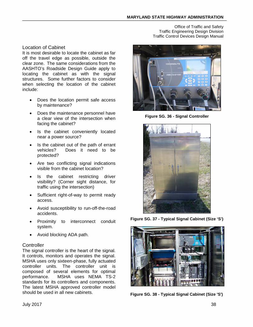
MARYLAND STATE HIGHWAY ADMINISTRATION
Office of Traffic and Safety Traffic Engineering Design Division
Traffic Control Devices Design Manual
July 2017 38
Location of Cabinet It is most desirable to locate the cabinet as far off the travel edge as possible, outside the clear zone. The same considerations from the AASHTO’s Roadside Design Guide apply to locating the cabinet as with the signal structures. Some further factors to consider when selecting the location of the cabinet include:
• Does the location permit safe access by maintenance?
• Does the maintenance personnel have a clear view of the intersection when facing the cabinet?
• Is the cabinet conveniently located near a power source?
• Is the cabinet out of the path of errant vehicles? Does it need to be protected?
• Are two conflicting signal indications visible from the cabinet location?
• Is the cabinet restricting driver visibility? (Corner sight distance, for traffic using the intersection)
• Sufficient right-of-way to permit ready access.
• Avoid susceptibility to run-off-the-road accidents.
• Proximity to interconnect conduit system.
• Avoid blocking ADA path.
Controller The signal controller is the heart of the signal. It controls, monitors and operates the signal. MSHA uses only sixteen-phase, fully actuated controller units. The controller unit is composed of several elements for optimal performance. MSHA uses NEMA TS-2 standards for its controllers and components. The latest MSHA approved controller model should be used in all new cabinets.
Figure SG. 36 - Signal Controller
Figure SG. 37 - Typical Signal Cabinet (Size ‘S’)
Figure SG. 38 - Typical Signal Cabinet (Size 'S')
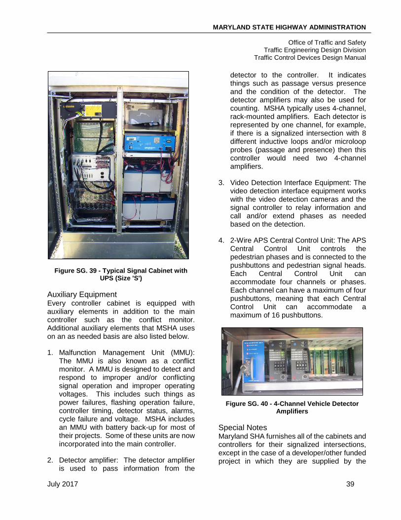
MARYLAND STATE HIGHWAY ADMINISTRATION
Office of Traffic and Safety Traffic Engineering Design Division
Traffic Control Devices Design Manual
July 2017 39
Figure SG. 39 - Typical Signal Cabinet with UPS (Size 'S')
Auxiliary Equipment Every controller cabinet is equipped with auxiliary elements in addition to the main controller such as the conflict monitor. Additional auxiliary elements that MSHA uses on an as needed basis are also listed below.
1. Malfunction Management Unit (MMU): The MMU is also known as a conflict monitor. A MMU is designed to detect and respond to improper and/or conflicting signal operation and improper operating voltages. This includes such things as power failures, flashing operation failure, controller timing, detector status, alarms, cycle failure and voltage. MSHA includes an MMU with battery back-up for most of their projects. Some of these units are now incorporated into the main controller.
2. Detector amplifier: The detector amplifier is used to pass information from the
detector to the controller. It indicates things such as passage versus presence and the condition of the detector. The detector amplifiers may also be used for counting. MSHA typically uses 4-channel, rack-mounted amplifiers. Each detector is represented by one channel, for example, if there is a signalized intersection with 8 different inductive loops and/or microloop probes (passage and presence) then this controller would need two 4-channel amplifiers.
3. Video Detection Interface Equipment: The video detection interface equipment works with the video detection cameras and the signal controller to relay information and call and/or extend phases as needed based on the detection.
4. 2-Wire APS Central Control Unit: The APS Central Control Unit controls the pedestrian phases and is connected to the pushbuttons and pedestrian signal heads. Each Central Control Unit can accommodate four channels or phases. Each channel can have a maximum of four pushbuttons, meaning that each Central Control Unit can accommodate a maximum of 16 pushbuttons.
Figure SG. 40 - 4-Channel Vehicle Detector
Amplifiers
Special Notes Maryland SHA furnishes all of the cabinets and controllers for their signalized intersections, except in the case of a developer/other funded project in which they are supplied by the
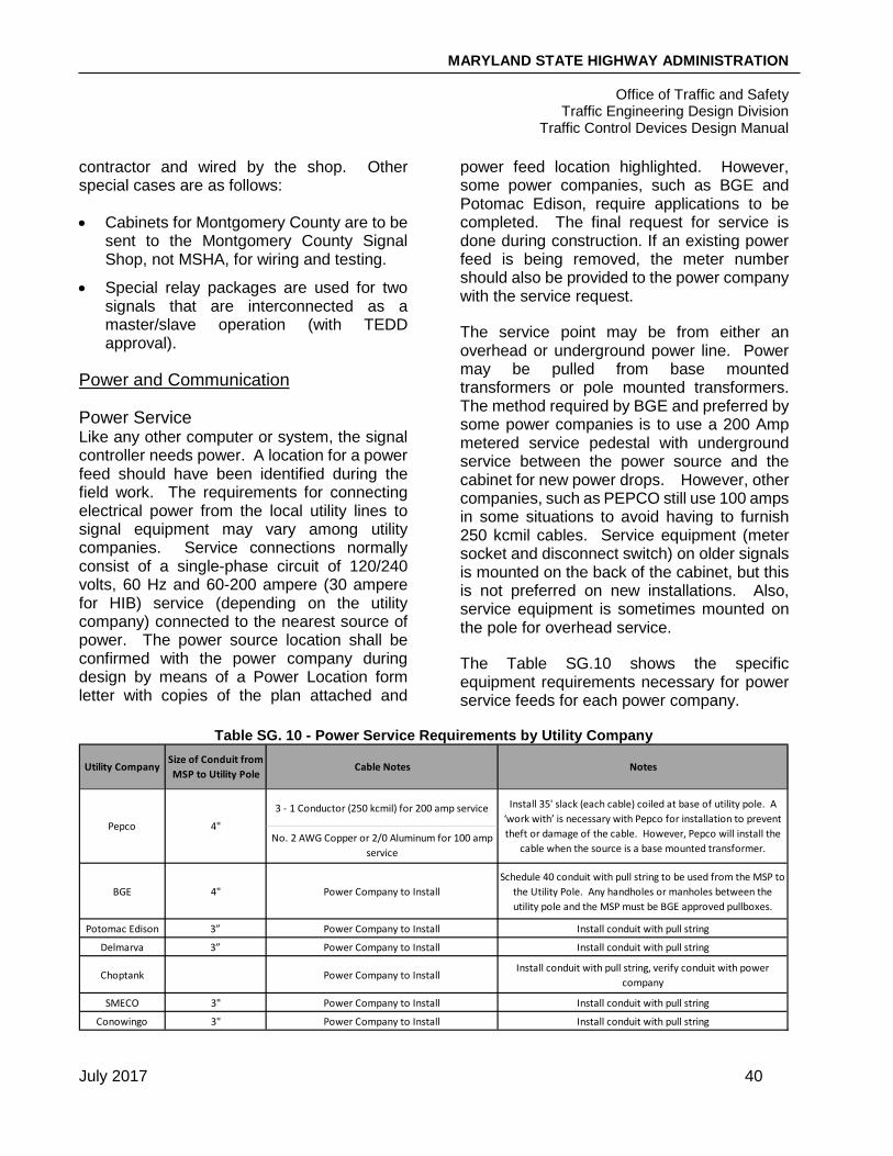
MARYLAND STATE HIGHWAY ADMINISTRATION
Office of Traffic and Safety Traffic Engineering Design Division
Traffic Control Devices Design Manual
July 2017 40
contractor and wired by the shop. Other special cases are as follows:
• Cabinets for Montgomery County are to be sent to the Montgomery County Signal Shop, not MSHA, for wiring and testing.
• Special relay packages are used for two signals that are interconnected as a master/slave operation (with TEDD approval).
Power and Communication
Power Service Like any other computer or system, the signal controller needs power. A location for a power feed should have been identified during the field work. The requirements for connecting electrical power from the local utility lines to signal equipment may vary among utility companies. Service connections normally consist of a single-phase circuit of 120/240 volts, 60 Hz and 60-200 ampere (30 ampere for HIB) service (depending on the utility company) connected to the nearest source of power. The power source location shall be confirmed with the power company during design by means of a Power Location form letter with copies of the plan attached and
power feed location highlighted. However, some power companies, such as BGE and Potomac Edison, require applications to be completed. The final request for service is done during construction. If an existing power feed is being removed, the meter number should also be provided to the power company with the service request.
The service point may be from either an overhead or underground power line. Power may be pulled from base mounted transformers or pole mounted transformers. The method required by BGE and preferred by some power companies is to use a 200 Amp metered service pedestal with underground service between the power source and the cabinet for new power drops. However, other companies, such as PEPCO still use 100 amps in some situations to avoid having to furnish 250 kcmil cables. Service equipment (meter socket and disconnect switch) on older signals is mounted on the back of the cabinet, but this is not preferred on new installations. Also, service equipment is sometimes mounted on the pole for overhead service.
The Table SG.10 shows the specific equipment requirements necessary for power service feeds for each power company.
Table SG. 10 - Power Service Requirements by Utility Company
Utility CompanySize of Conduit from MSP to Utility Pole
Cable Notes Notes
3 - 1 Conductor (250 kcmil) for 200 amp service
No. 2 AWG Copper or 2/0 Aluminum for 100 amp service
BGE 4" Power Company to InstallSchedule 40 conduit with pull string to be used from the MSP to
the Utility Pole. Any handholes or manholes between the utility pole and the MSP must be BGE approved pullboxes.
Potomac Edison 3” Power Company to Install Install conduit with pull string
Delmarva 3” Power Company to Install Install conduit with pull string
Choptank Power Company to InstallInstall conduit with pull string, verify conduit with power
company
SMECO 3" Power Company to Install Install conduit with pull string
Conowingo 3" Power Company to Install Install conduit with pull string
Pepco 4"
Install 35' slack (each cable) coiled at base of utility pole. A ‘work with’ is necessary with Pepco for installation to prevent theft or damage of the cable. However, Pepco will install the
cable when the source is a base mounted transformer.

MARYLAND STATE HIGHWAY ADMINISTRATION
Office of Traffic and Safety Traffic Engineering Design Division
Traffic Control Devices Design Manual
July 2017 41
Uninterrupted Power Supply (UPS) To prevent down time (or unnecessary activation of flash mode) at signals in the event of a power outage, MSHA is installing UPSs, also known as battery backups, at targeted intersections. The UPS will allow the signal to remain operational for a short period of time until maintenance crews are able to restore power. UPSs shall be installed at locations fitting the following criteria:
• Railroad pre-emption
• Airport obstruction lights (aircraft warning beacons)
• Military base entrances
• Interstate, US route, and State route ramps
• Multi-intersection controller units
• Single point control intersections
• TSSM Hubbette
• System master controllers
• Interactive advance warning beacons (i.e. HIB for red signal warning)
• Multiple left or right turn lanes in same direction
• Unusual geometrics
• Other Agency/Local Jurisdiction Initiatives
Communication Maryland SHA uses cellular modems to provide wireless, high speed data communications to maintain and operate the signals. MSHA uses the Centracs central management system software in order to monitor and manage traffic signal assets. Centracs allows the use of an Adaptive traffic signal timing module in locations warranted by MSHA and also allows a nearly unlimited
number of traffic signals to be coordinated. All new signals should use wireless communications and any modifications or reconstructions of existing signals should implement wireless communications if they do not already exist at the location. However, it should be noted that signals that are managed or maintained by local jurisdictions rather than MSHA, may use other communication sources and methods.
Wireless communications should be considered during the design phase of a project. The location of the cellular antenna should be carefully considered and shown on the signal plans. The antenna should be located in the area with the best possible cellular signal strength. Some preferred antenna locations include areas with higher elevation, close proximity to interstate roadways, and areas away from any buildings or structures that may block signals. Typically, the antenna should be installed on a mast arm pole or strain pole in the same quadrant of the intersection as the cabinet.
The design should also include cellular antenna lead-in cable and conduit. The preferred maximum length for the lead-in cable is 125 feet using a 400 series coax cable. This maximum length also includes the height of the pole or structure on which it is mounted. When designing the lead-in cable and conduit, the capacity of the conduit must be confirmed. The 400 series coax cable has a diameter of approximately 0.53 inches. If an antenna location cannot be found to meet the maximum length of 125 feet, a larger coax cable may be required. However, this should be brought to the attention of the TEDD project manager and discussed as early in the design process as possible. At signal locations where cellular strength is poor and no other options exist for antenna placement, larger antennas may be considered and should be discussed with the TEDD project manager and with the Office of Information Technology (OIT).

MARYLAND STATE HIGHWAY ADMINISTRATION
Office of Traffic and Safety Traffic Engineering Design Division
Traffic Control Devices Design Manual
July 2017 42
During the construction of a project involving the installation of wireless communications, MSHA will furnish the cellular antenna and the cellular antenna lead-in cable to be installed by the contractor. MSHA will furnish and install the cellular modems and Ethernet switches. As wireless communications are implemented, TOD will request the disconnection of existing phone drop communication service.
The use of Centracs for interconnected signals is described in the following systemization section. Further information about Centracs can be found in the MSHA memo titled “Centracs Advanced Transportation Management System (ATMS) Implementation and Design Guidance for Traffic Signals.”
SIGNAL SYSTEMIZATION
A signal system is interconnecting two or more signals along a roadway or network of roadways. There are two basic types of signal systems, open-loop system and closed-loop system.
An open-loop system operates the intersection controller, but does not receive feedback status. It may operate with a master controller that supervises the cycle length, offsets and splits for each signal or it may operate without a master controller as a coordinated system of intersections. An example of this is where GPS time receivers are installed in each cabinet of their ‘system’ without hardwire interconnect. The coordination is maintained using Time of Day coordination plans and syncing the clocks using the GPS receivers. This is done in areas where it is not physically possible to run hardwire interconnect.
A closed-loop system provides two-way communication between the intersection controller and the signal shop via the cellular modem and wireless antenna dedicated to the system. This communication used to be performed by an on-street master controller. With a closed-loop system, the traffic signal
central management software at the signal shop will receive and respond to diagnostic information such as speed, density, volume and capacity.
If existing hardwired interconnect is present at an intersection/along a corridor that is being modified or reconstructed, the entire system of interconnected signals should be upgraded to implement wireless communications. When existing interconnect is present, the proposed design should be constructed without causing any down time to the existing system. In some cases, temporary interconnect may be required for this to be achieved.
A signal system has three major components in the design process:
1. Controller (as described in prior sections of this manual)
2. Communication Links
3. System Detection (as described in prior sections of this manual)
Wireless Communications A cellular modem, antenna, and lead-in cable is required at one signal within an interconnected system. The antenna and lead-in cable design for this signal should be the same as described in the communication section above. The location can be anywhere within the system that would provide the best possible cellular signal strength. For all interconnected systems that have not been upgraded to wireless communications, the first project to occur at a signal within the system must convert all locations within the system to be compatible with the traffic signal central management software (Centracs). The on-street master controller will no longer be used with Centracs and should be called for removal by MSHA as part of the Centracs conversion.
Signals within a system that do not have a cellular modem and antenna must have an Ethernet switch installed in the cabinet to

MARYLAND STATE HIGHWAY ADMINISTRATION
Office of Traffic and Safety Traffic Engineering Design Division
Traffic Control Devices Design Manual
July 2017 43
connect to the fiber or twisted pair copper cable. In locations where two interconnected systems cross, the cabinet must include two Ethernet switches.
Communication Links In order to implement a signal system, the local intersection controllers must be interconnected via communication links. Communication links may be designed using several different techniques. Some of these may include:
• Cable
• Wireless
• Leased CATV Cable Channels
• Switched Telecommunication Service
Wiring While Maryland now uses wireless communications to connect to the signal shop, cable is used for its communication links. Two common types of cable are twisted pair and fiber optic. Cable may be run overhead or underground.
Interconnect cables are generally 12-pair jelly-filled, No. 19 A.W.G., for underground installations and/or 12-pair self-supporting, No. 19 A.W.G., for overhead installations. The decision to install interconnect cables underground versus overhead should be based on cost and constructability. If both underground and overhead installation is necessary, a 12-pair self-supporting cable is used throughout the entire run. Other types and sizes of interconnect cable may be requested by a local jurisdiction such as 50-pair cable in Montgomery County. Interconnect cable is not typically spliced, with the exception of Montgomery County where interconnect may be spliced with splice kits (rather than splice boxes) with approval from the Administration and the County.
Underground
When the design incorporates underground communication links, PVC conduit is used as with signalized intersections
Figure SG. 41 - 12-Pair Interconnect Cables
Overhead An overhead utility company attachment agreement is required if interconnect cables are to be placed on telephone, electric company or joint use poles.
Overhead attachment details should be shown on the plan to indicate how the interconnect cables should be installed, e.g., face of pole, height, support and clearance from other utilities and overhead clearances over driveway entrances. This element of the design can be the most critical aspect of the project. The Designer is responsible for the coordination of the overhead attachment agreement and any adjustments required with the owners of the overhead utilities. Where cable transitions from overhead to a pole mounted cabinet or to underground conduits, a

MARYLAND STATE HIGHWAY ADMINISTRATION
Office of Traffic and Safety Traffic Engineering Design Division
Traffic Control Devices Design Manual
July 2017 44
riser should be installed on the utility pole in accordance with owner requirements.
SIGNS
A signal plan may include some signing when designed independent of a signing and marking plan. The types of signing to be installed will be as indicated in the Design Request, and/or as required for proper operation of the intersection. The placement of the sign should take into consideration the size of the sign, position over travel lanes and offset from the nearest signal head to the edge of the sign plate. When installing a sign on the mast arm (overhead), the designer should maintain a 17’ clearance from the bottom of the sign to the roadway. Associated signs may include:
• Overhead Street Name Signs – D-3(1) signs are typically installed on all legs of an intersection. They are mounted near left and far right, dual-faced. When the intersecting street has different names on either side of the intersection, the left side street name is shown on the left sign, and the right side street name on the right sign. Street name signs should have a maximum height of 20” on span wires, be installed back to back on mast arms if height is over 20” and dual faced if height is 16” or 20”.
• Route Marker Assemblies – At intersections along numbered routes, an associated shield assembly is mounted near right and far left facing the minor street traffic. Preferably, the assembly should be mounted on the signal support upright, installed parallel to the main road. When this is not feasible, the assembly (on one sheet aluminum panel with a black background) is mounted on wood sign supports instead, as shown in Figure SG. 42 - Route Marker Assemblies at Signalized Intersections. Based on dimensions in the MSHA Sign Standard
Book, a standard sized associated shield assembly should be used for nearside (right arrow) signs and oversized signs should be used for far side (left arrow) signs.
Figure SG. 42 - Route Marker Assemblies at
Signalized Intersections
• Signal Warning Signs – Signal ahead symbol (W3-3) sign(s) shall be installed on the approach to an intersection when the signal visibility requirements listed in the MdMUTCD cannot be met and for all new signals. A single sign will be used on two-lane, two way and multilane, undivided roadways. Two side-by-side signs, one on the outside and one in the median, will be used on divided highways. The sign(s) shall be located in accordance with the latest approved version of the MdMUTCD. For advance placement of warning signs, use the 85th percentile speed.
For new signals, a W16-14(1) “NEW” panel should be mounted above the W3-3 sign panel with two flags mounted midway along the top sides of the sign panel on both mainline approaches. These signs are also required on side road approaches with speeds over 35 MPH. The flags and new panel will remain in place for a period of 90 days at which time MSHA District Forces

MARYLAND STATE HIGHWAY ADMINISTRATION
Office of Traffic and Safety Traffic Engineering Design Division
Traffic Control Devices Design Manual
July 2017 45
will remove them. If the W3-3 sign is not warranted, the District should remove it as well.
• Advanced street name signs should be installed on all approaches where a State route intersects another State route, whether signalized or not. They should also be installed along the State route in advance of a signalized intersection between a State route and a local road. Advanced street name signs should be white on green, except where a W3-3 sign is permanently required. In this case the sign should be black on yellow and installed on the same supports as the W3-3 sign.
• Lane Use Control Signs – R3-5 through R3-8, when used shall be placed on the far side of the intersection, centered over the center of the lane(s) or a projection of the lane(s) to which it applies, according to MdMUTCD guidance.
• Other Signs – Additional regulatory and warning signs should be installed, as appropriate, for control of the intersection. Such signs include “no turn on red” and pedestrian warning signs. The sign(s) shall be located in accordance with the pertinent section of the MdMUTCD.
When a STOP controlled intersection is being converted to signalized control, the contractor shall be instructed, through the Construction Details, to remove the STOP signs immediately after the signal becomes operational.
PAVEMENT MARKINGS
A signal plan may also include some pavement marking design when designed independent of signing and marking plans. The types of pavement markings to be installed will be indicated in the Design Request. They may include crosswalks, stop lines, message/arrow markings, lane lines, channelizing lines, edge lines, and the removal of existing markings.
The Designer is responsible for detailing new pavement markings to a point where they can be transitioned into the existing markings.
LIGHTING
Lighting as part of a signal design is termed intersection lighting. All signal designs should include intersection lighting. This is lighting typically attached to the signal poles via a bracket arm. Available luminaire arm lengths are 10 feet, 15 feet, and 20 feet. The lighting is wired directly to the luminaire from the metered service pedestal and bypasses the cabinet. In other cases, intersection lighting may be accomplished by leased lighting in situations where adequate space on a signal pole is not available or where overhead utilities would conflict. All new luminaires shall be LED and all existing non-standard lighting should be upgraded to LED luminaries as part of a signal modification. . Refer to the MSHA Lighting Guidelines for more information on adding lights to signal poles.
PLAN PREPARATION
Developing a Concept Layout A conceptual layout or preliminary design is developed before the final signal plan is designed. A concept shall be developed for both individual signalized intersections and signal systems. Based on discussions at the field PI meeting, the designer will develop what he feels is the desired layout prior to completing a design. This conceptual design sets the foundation for the signal design. Although conceptual layouts are typically not submitted to TEDD for distribution, the designer can seek input from the parties involved including the project manager, team leader and district traffic office as a confirmation of decisions made in the field.
The goal of the conceptual layout is to put on paper what the designer feels is the desired configuration of the major signal components including the poles, cabinet and signal heads.
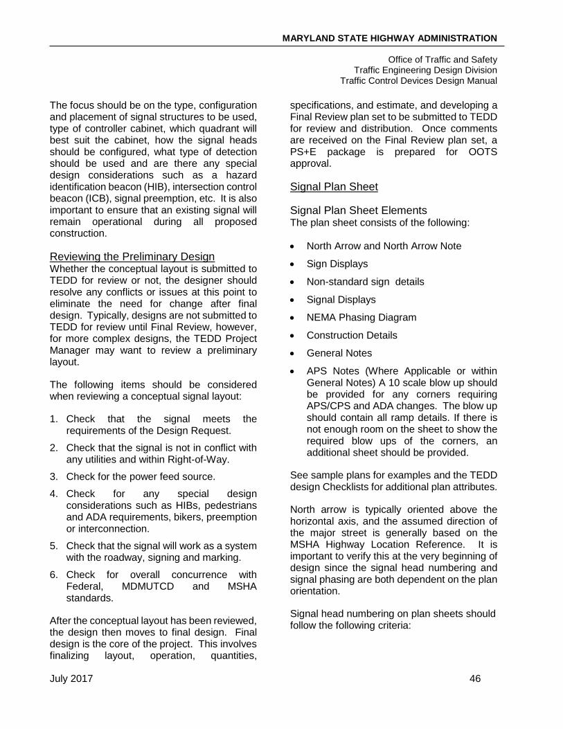
MARYLAND STATE HIGHWAY ADMINISTRATION
Office of Traffic and Safety Traffic Engineering Design Division
Traffic Control Devices Design Manual
July 2017 46
The focus should be on the type, configuration and placement of signal structures to be used, type of controller cabinet, which quadrant will best suit the cabinet, how the signal heads should be configured, what type of detection should be used and are there any special design considerations such as a hazard identification beacon (HIB), intersection control beacon (ICB), signal preemption, etc. It is also important to ensure that an existing signal will remain operational during all proposed construction.
Reviewing the Preliminary Design Whether the conceptual layout is submitted to TEDD for review or not, the designer should resolve any conflicts or issues at this point to eliminate the need for change after final design. Typically, designs are not submitted to TEDD for review until Final Review, however, for more complex designs, the TEDD Project Manager may want to review a preliminary layout.
The following items should be considered when reviewing a conceptual signal layout:
1. Check that the signal meets the requirements of the Design Request.
2. Check that the signal is not in conflict with any utilities and within Right-of-Way.
3. Check for the power feed source.
4. Check for any special design considerations such as HIBs, pedestrians and ADA requirements, bikers, preemption or interconnection.
5. Check that the signal will work as a system with the roadway, signing and marking.
6. Check for overall concurrence with Federal, MDMUTCD and MSHA standards.
After the conceptual layout has been reviewed, the design then moves to final design. Final design is the core of the project. This involves finalizing layout, operation, quantities,
specifications, and estimate, and developing a Final Review plan set to be submitted to TEDD for review and distribution. Once comments are received on the Final Review plan set, a PS+E package is prepared for OOTS approval.
Signal Plan Sheet
Signal Plan Sheet Elements The plan sheet consists of the following:
• North Arrow and North Arrow Note
• Sign Displays
• Non-standard sign details
• Signal Displays
• NEMA Phasing Diagram
• Construction Details
• General Notes
• APS Notes (Where Applicable or within General Notes) A 10 scale blow up should be provided for any corners requiring APS/CPS and ADA changes. The blow up should contain all ramp details. If there is not enough room on the sheet to show the required blow ups of the corners, an additional sheet should be provided.
See sample plans for examples and the TEDD design Checklists for additional plan attributes.
North arrow is typically oriented above the horizontal axis, and the assumed direction of the major street is generally based on the MSHA Highway Location Reference. It is important to verify this at the very beginning of design since the signal head numbering and signal phasing are both dependent on the plan orientation.
Signal head numbering on plan sheets should follow the following criteria:

MARYLAND STATE HIGHWAY ADMINISTRATION
Office of Traffic and Safety Traffic Engineering Design Division
Traffic Control Devices Design Manual
July 2017 47
• Mainline signals are numbered first starting with either signal heads facing northbound traffic or eastbound traffic
• Minor roads are numbered after mainline roads following the same rules (starting with northbound or eastbound traffic)
• Signal heads are numbered in increasing order from left to right
• Near side signal heads are numbered first on each approach
• Pedestrian heads and signs are numbered last using the same rules
Construction Details These notes are used to convey information about how the signal equipment is to be installed or removed. They are identified in alphabetic order starting with “A.” If there are more than 26 notes, use AA, BB, etc. Construction details have associated callouts on the plan that consists of an arrow pointing to the specific area of work and includes the corresponding letter inside a shape, such as a circle around them. The shape used for callouts should match the shape used around the revision letter in the title block. The same letter may appear in more than one callout. For example, the letter for “Install handhole” will appear as many times as there are new handholes. If there is insufficient space on the plan sheet for the Construction Details, they may be shown on the General Information Sheet.
NEMA Phasing Phasing is assigning the Right-of-Way and combination of one or more movements that can occur concurrently during a cycle. MSHA uses the standard National Electrical Manufacturers Association (NEMA) phasing for signal operation.
The phase numbering and sequencing are shown diagrammatically in the upper right-hand corner of the plan sheet. It allows the designer, contractor and MSHA to know the operation of the signal. Some of this information is obtained from the DR. The DR
usually indicates if there are any exclusive or exclusive permissive movements or any special phasing. This can be used as the starting point for designing the phasing. Below is the standard convention used to determine phase numbering as adopted by MSHA. Additional examples of NEMA phasing diagrams based on different orientations of the north arrow can be obtained by request from TEDD. Phases associated by a dashed line may operate concurrently. Phases associated by a solid line will not operate concurrently. Further, the arrow heads should be solid if there is a proposed change to that phase and should be hollow if no change is being proposed to an individual phase. If the signal has lead/lag phasing for turning movements, the appropriate phase number should be identified as being either “LEAD” or “LAG”, and the lead/lag phasing should be noted in the phasing notes under the phasing diagram by stating “Phase X will lag behind Phase Y”.
A split phase is the operation of opposing movements at separate times. For example, the northbound and southbound traffic move simultaneously, then the eastbound traffic proceeds and last is the westbound traffic. The eastbound/westbound traffic is considered a split phase. If the side street phasing is split, the side streets use Phases 3 and 4 only. The side street approach movement with the heavier volume should be designated as Phase 4. Further, at a ‘T’ intersection, the side street is always Phase 4 as well.
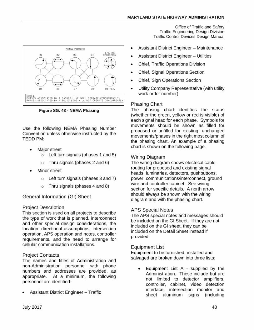
MARYLAND STATE HIGHWAY ADMINISTRATION
Office of Traffic and Safety Traffic Engineering Design Division
Traffic Control Devices Design Manual
July 2017 48
Figure SG. 43 - NEMA Phasing
Use the following NEMA Phasing Number Convention unless otherwise instructed by the TEDD PM:
• Major street o Left turn signals (phases 1 and 5)
o Thru signals (phases 2 and 6)
• Minor street
o Left turn signals (phases 3 and 7)
o Thru signals (phases 4 and 8)
General Information (GI) Sheet
Project Description This section is used on all projects to describe the type of work that is planned, interconnect and other special design considerations, the location, directional assumptions, intersection operation, APS operation and notes, controller requirements, and the need to arrange for cellular communication installations.
Project Contacts The names and titles of Administration and non-Administration personnel with phone numbers and addresses are provided, as appropriate. At a minimum, the following personnel are identified:
• Assistant District Engineer – Traffic
• Assistant District Engineer – Maintenance
• Assistant District Engineer – Utilities
• Chief, Traffic Operations Division
• Chief, Signal Operations Section
• Chief, Sign Operations Section
• Utility Company Representative (with utility work order number)
Phasing Chart The phasing chart identifies the status (whether the green, yellow or red is visible) of each signal head for each phase. Symbols for movements should be shown as filled for proposed or unfilled for existing, unchanged movements/phases in the right most column of the phasing chart. An example of a phasing chart is shown on the following page.
Wiring Diagram The wiring diagram shows electrical cable routing for proposed and existing signal heads, luminaries, detectors, pushbuttons, power, communications/interconnect, ground wire and controller cabinet. See wiring section for specific details. A north arrow should always be shown with the wiring diagram and with the phasing chart.
APS Special Notes The APS special notes and messages should be included on the GI Sheet. If they are not included on the GI sheet, they can be included on the Detail Sheet instead if provided.
Equipment List Equipment to be furnished, installed and salvaged are broken down into three lists:
• Equipment List A - supplied by the Administration. These include but are not limited to detector amplifiers, controller, cabinet, video detection interface, intersection monitor and sheet aluminum signs (including

MARYLAND STATE HIGHWAY ADMINISTRATION
Office of Traffic and Safety Traffic Engineering Design Division
Traffic Control Devices Design Manual
July 2017 49
hardware). For developer, design-build and local/state agency signal projects, it is the applicant’s responsibility to furnish and install all materials for traffic signal work. Catalog cuts must be submitted and accepted for all materials prior to their installation. All new controllers and cabinets shall be delivered to the Chief Signal Operations Section a minimum of 21 days prior to their installation for wiring and testing.

MARYLAND STATE HIGHWAY ADMINISTRATION
Office of Traffic and Safety Traffic Engineering Design Division
Traffic Control Devices Design Manual
July 2017 50
Figure SG. 44 - Sample Phasing Chart

MARYLAND STATE HIGHWAY ADMINISTRATION
Office of Traffic and Safety Traffic Engineering Design Division
Traffic Control Devices Design Manual
July 2017 51
• Equipment List B – furnished and/or installed by the Contractor. Construction items are obtained by reviewing the construction details and wiring diagram and making sure all materials and equipment are included. Their formats may vary by contract type, as some items are incidental to other items especially in Areawide projects. Additional items must be included but do not appear elsewhere in the construction details or on the wiring diagram. They may include test pit excavation and maintenance of traffic.
• Equipment List C – to be removed by the Contractor and delivered to MSHA. If the existing controller equipment is being replaced, the existing controller and auxiliary equipment are to be returned to OOTS. If the signal is maintained by Montgomery County, it shall be returned to the Montgomery County Signal Shop. All other equipment shall become the property of the Contractor.
PREPARATION OF AS-BUILTS
As-Built traffic signal plans document the operational and physical conditions of newly constructed traffic signals. As-Built plans are required for all construction activities that change the functional operation of the intersection.
The physical and operational elements of an As-Built plan should include accurate field verification of the following:
• Location of traffic signal equipment (poles, handholes, cabinet and conduits).
• Location of detectors and lead-in cables.
• Location and type of pavement markings.
• Location of signal heads on mast arms or span wires.
• Location of intersection signing and lighting.
• Clearances to overhead utilities.
With As-Built plans, the Construction Details from the original signal plan sheet should be updated to be labels rather than action items. For example, if the symbol (E) on the original plans said “Install Handhole”, the symbol (E) on the As-Built plan would simply say “Handhole”.
An As-Built plan consists of a single plan sheet and contains the following information:
• NEMA phasing chart.
• Existing signs and signals.
• Wiring diagram and a wiring key (placed on the right-hand side above the title block).
• Legend of geometrics and utilities.
For developer, design-build and local/state agency signal projects, it is the applicant’s responsibility to furnish the Project Manager with an electronic copy of the as-built plans, documenting any significant changes from the approved design, in the latest MicroStation format approved by MSHA.