Embed Size (px)
Citation preview
NMDOT Design Manual 1000-1
1000 Geometrics
1000.1 General
The geometrics of a roadway consist of its horizontal alignment,
vertical alignment, and cross section elements. The New Mexico
Department of Transportation (NMDOT) has accepted the
American Association of State Highway and Transportation
Officials (AASHTO) A Policy on Geometric Design of Highways
and Streets (Green Book) as its standard for geometric design. For
projects on the interstate system, AASHTO’s A Policy on Design
Standards - Interstate System supplements the Green Book.
Designers are directed to the above-referenced documents for
geometric design criteria. This chapter does not attempt to restate
criteria contained in the Green Book; rather, it provides criteria
specific to the NMDOT where it is different or more limiting than
what AASHTO allows. In instances where these criteria cannot be
met, Chapter 210 of the Design Manual describes NMDOT’s
documentation procedures for design exceptions and design
variances.

1000-2 Geometrics
1000.2 References
The following references are used in the design of roadway
geometrics. Conformance with federal and state laws and codes is
required.
1000.2.1 Federal/State Laws and Codes
23 Code of Federal Regulations (CFR) Part 625.4, Design
Standards for Highways, Standards, Policies, and Standard
Specifications.
18.31.6 New Mexico Administrative Code (NMAC), State
Highway Access Management Requirements (State Access
Management Manual [SAMM]).
1000.2.2 Design Guidance
A Policy on the Geometric Design of Highways and Streets
(Green Book), AASHTO, current edition.
A Policy on Design Standards - Interstate System, AASHTO,
2005.
Guidelines for Geometric Design of Very Low-Volume Local
Roads (Average Daily Traffic [ADT] ≤ 400), AASHTO, current
edition.
Guide for the Planning, Design, and Operation of Pedestrian
Facilities, AASHTO, current edition.
Guide for the Development of Bicycle Facilities, AASHTO,
current edition.
Interstate System Access Informational Guide, Federal Highway
Administration (FHWA), 2010.
Manual on Uniform Traffic Control Devices for Streets and
Highways (MUTCD), United States Department of
Transportation (USDOT), FHWA, current edition.
NMDOT Functional Classification System Map, current version.
NMDOT Standard Drawings.
Accessibility Guidelines for Pedestrian Facilities in the Public
Right-of-Way, (PROWAG), SNPRM, 2013.
Roadside Design Guide, AASHTO, current edition.
NMDOT Design Manual 1000-3
1000.3 Definitions
Refer to the Green Book, Chapter 2 of the SAMM, and the reference
documents listed above for relevant definitions.
1000.4 Design Controls and Elements
In order to optimize or improve roadway design, the characteristics
and criteria of vehicles, pedestrians, and traffic must be explicitly
considered as discussed below.
1000.4.1 Functional Class
The functional classification of a roadway will guide the design
criteria to be used for roadway design. The NMDOT’s Functional
Classification System Map provides roadway classifications for all
interstates and state roads in New Mexico. For facilities within
Metropolitan Planning Organizations (MPOs), current roadway
classifications are provided on each MPOs functional classification
maps.
1000.4.2 Design Vehicle
The design vehicle is generally the largest vehicle that is likely to
use a facility with considerable frequency. It is typically determined
from vehicle classification counts performed for existing facilities
and its selection is important and directly related to such critical
features as radii at intersections and radii of turning roadways. Per
18.31.6 NMAC, the design vehicle is subject to the approval of the
District Traffic Engineer. There are four general classes of design
vehicles: passenger cars, buses, trucks, and recreational vehicles.
The passenger car class includes sport-utility vehicles (SUVs),
minivans, and pick-up trucks. The bus class includes city transit,
school buses, and articulated buses. The truck class includes
single-unit and truck tractor-semitrailer combinations. The
recreational vehicle class includes motor homes and cars with
camper or boat trailers. More detailed discussion of the vehicles
classes can be found in Chapter 2 of the Green Book.
1000-4 Geometrics
1000.4.3 Traffic Characteristics
Traffic characteristics such as volume, typically expressed as
average daily traffic (ADT), peak-hour traffic, directional
distribution, and traffic composition should all be considered in the
design of a roadway and its features. These characteristics are
gleaned through data collection on existing facilities, and directly
influence the selection of geometric design features such as the
number of lanes, widths, alignments, and grades.
1000.4.4 Design Speed
Roadways should be designed to support vehicle operation at a
speed that accommodates safe driving. Design speed is the control
by which a facility is designed so that the facility fits the travel
desires and habits of nearly all drivers expected to use it.
Design speed is a selected speed used to determine the various
geometric design features of the roadway and to establish the
limiting values of curve radius and minimum sight distance. It is
often established based on current posted speeds. The selection of
design speed for a roadway project should be done in coordination
with the NMDOT.
1000.4.4.1 Low Speed vs. High Speed Design
The Green Book Chapter 2, Design Controls and Criteria, discusses
speed and the differences between the design criteria applicable to
low and high speed design. It defines the upper limit for low-speed
design as 45 miles per hour (mph), and the lower limit for
high-speed design as 50 mph.
1000.4.5 Capacity
Roadway capacity is discussed in the SAMM.
1000.4.6 Access Control and Access Management
A roadway’s access control directly affects its service and safety, in
terms of crash frequency and severity. Access control serves to
manage the interference with through traffic from vehicles and
pedestrians entering, leaving, and crossing the roadway. NMDOT’s
SAMM provides guidelines and criteria for the design of access
points on state roads and non-National Highway System US routes.
NMDOT Design Manual 1000-5
Guidelines for interstates can be found in FHWA’s Interstate
System Access Informational Guide.
1000.4.7 Pedestrian and Bicycle Facilities
Interactions of pedestrians and bicyclists with traffic are a major
consideration in roadway planning and design. AASHTO’s Guide
for the Planning, Design, and Operation of Pedestrian Facilities and
Guide for the Development of Bicycle Facilities contain design
guidelines and criteria.
1000.4.8 Safety
The safety of a roadway is related to a number of factors such as
roadway design, roadside design, and traffic control devices.
Improving safety by reducing the number and severity of crashes
involves consideration of speed, traffic volumes, access control, and
reducing the need for driver decisions, among many factors.
The Roadside Design Guide shall be referred to in optimizing
roadside safety. The MUTCD shall be used for implementing
standards for traffic control devices.
1000.4.9 Sight Distance
Sight distance is one of the principal elements of design that is
common to all classes of highways and streets. It is the length of the
roadway that is visible to the driver and is a function of design
speed, brake reaction time, and deceleration rate. Values for and
criteria to measure sight distance are provided in the Green Book.
Additionally, the SAMM provides sight distance requirements for
access points on state roads.
1000.4.10 Drainage, Utilities and the Environment
Drainage, utilities, and the environment are additional elements
that influence geometric design and should be considered during
the design of a roadway project.
1000.5 Horizontal and Vertical Alignment
Horizontal and vertical alignments (see Section 1000.5.5) are the
primary controlling elements for highway design. It is important to
coordinate these two elements with design speed, drainage, and
1000-6 Geometrics
intersection design in the early stages of design. Horizontal curve
radii and curve length criteria are provided in the Green Book.
1000.5.1 Horizontal Curves
The NMDOT generally uses simple curves in horizontal alignment
design. The NMDOT discourages the use of compound curves on
the highway mainline and only allows their use to meet field
conditions where a simple curve is not obtainable (e.g., to avoid
obstructions that cannot be relocated). When compound curves are
used on the highway mainline, it is preferable that the ratio of the
flatter radius to the sharper radius not exceed 1.5 to 1.
1000.5.2 Maximum Deflection Angle without a
Horizontal Curve
It may be appropriate to design a facility without a horizontal curve
where small deflection angles are present. As a guide, the designer
may retain deflection angles of approximately 30 minutes or less for
mainline through-traffic conditions.
1000.5.3 Minimum Curve Length
Criteria for the minimum length of curve is found in the Green
Book and reiterated here. The designer should refer to the Green
Book for further information. The NMDOT minimum curve length,
Lcmin, should be 500 feet long for a central angle of five degrees. The
minimum lengths should be increased 100 feet for each one degree
decrease in the central angle. The minimum length of curves on low
speed urban streets will be determined on a case-by-case basis.
1000.5.3.1 All Major Highways
The minimum curve length, Lcmin, should be 15V, where V equals
the design speed in mph.
1000.5.3.2 Freeways
For aesthetics, it is desirable that the minimum length of curve be
30V, where V equals the design speed in mph.
1000.5.4 Superelevation
The Green Book provides maximum superelevation (emax) rates of
up to 12 percent. However, the NMDOT limits the maximum
superelevation rate to six percent.
NMDOT Design Manual 1000-7
1000.5.4.1 Superelevation Methods
The NMDOT uses two methods, Method 5 and Method 2 as
described in the Green Book, to distribute superelevation and side
friction factor. They are commonly referred to as the open roadway
method and the low-speed urban street method.
The open roadway method uses Method 5 and applies to all rural
facilities and all urban facilities where the design speed, V, exceeds
45 mph.
The low-speed urban street method uses Method 2. The practical
effect of Method 2 is that superelevation is rarely warranted on low
speed streets (design speed ≤ 45 mph).
1000.5.4.2 Superelevation Transitions
Superelevation transitions include a tangent runout and a
superelevation runoff. Minimum lengths for these elements shall be
determined from the Green Book.
1000.5.4.3 Location of Runoff with Respect to End of Curve
The NMDOT recommends the use of Green Book Table 3-18,
“Runoff Locations that Minimize the Vehicle’s Lateral Motion,” to
determine the proportion of runoff length on the tangent. The
designer, if referring to NMDOT Standard Drawing 801-01-1/4, is
advised to use the Green Book values.
1000.5.5 Vertical Alignment
The vertical alignment, or roadway profile, consists of a series of
gradients connected by vertical curves. The designer should refer to
the Green Book for criteria for minimum length (or K-value) of
vertical curves, maximum/minimum grade, and other design
criteria.
1000.6 Cross Section Elements
Cross section elements are determined by functional classification
criteria, traffic volume, and whether the roadway is in a rural or
urban area. General guidelines from the Green Book and the
SAMM are summarized below.
1000-8 Geometrics
1000.6.1 Lane Width
Twelve-foot lanes are predominant on high-speed, high-volume
highways. In urban areas, 11-foot lane widths may be appropriate.
1000.6.2 Auxiliary Lanes
The SAMM requires 12-foot auxiliary lane widths. The Green Book
recommends a width of 10 feet to 16 feet for continuous two-way
left turn lanes.
1000.6.3 Shoulder Width
For higher speed, high volume roads, the NMDOT has adopted
ten feet as the normal shoulder width.
For low-volume roads, a minimum shoulder width of two feet
is required, though six feet to eight feet is preferable.
Where bicycles and/or pedestrians are to be accommodated on
shoulders, the minimum usable width (i.e., clear of rumble
strips and gutter pan width) is four feet.
1000.6.4 Minimum Cross Slope
For new construction or reconstruction (4R) projects, the minimum
roadway cross slope will be two percent. The shoulder cross slope
will match the driving lane cross slope. See Exhibit 1000-1.
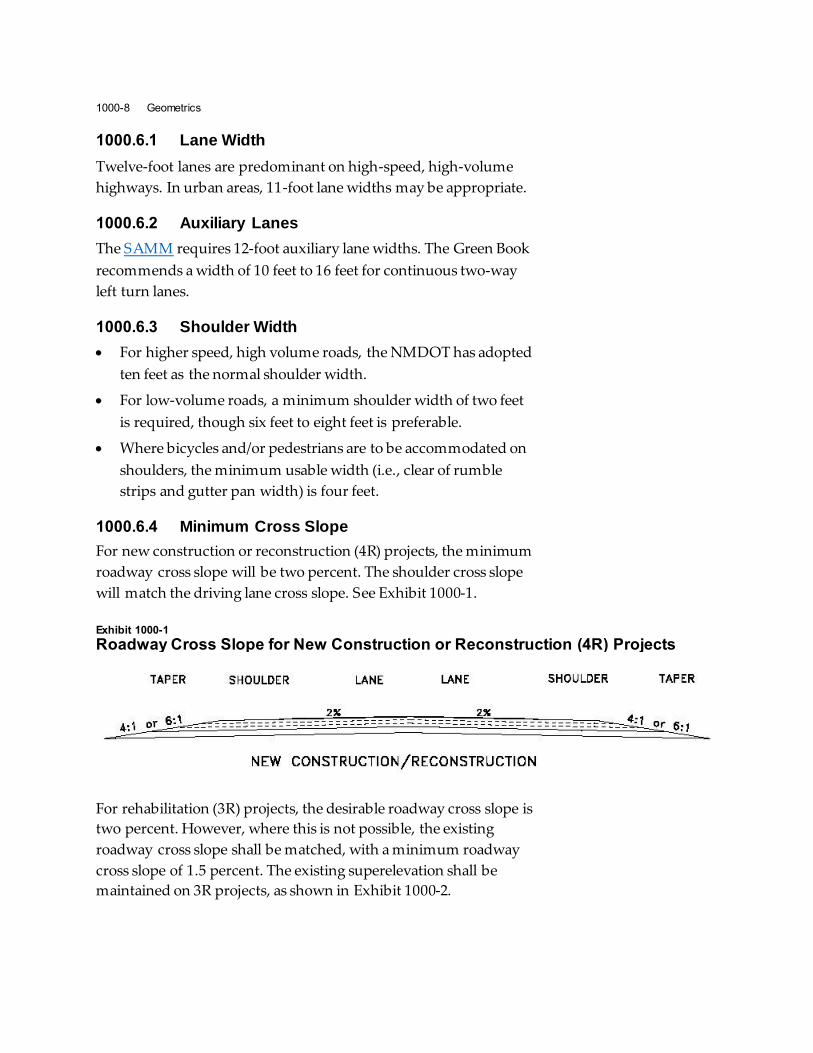
Exhibit 1000-1
Roadway Cross Slope for New Construction or Reconstruction (4R) Projects
For rehabilitation (3R) projects, the desirable roadway cross slope is
two percent. However, where this is not possible, the existing
roadway cross slope shall be matched, with a minimum roadway
cross slope of 1.5 percent. The existing superelevation shall be
maintained on 3R projects, as shown in Exhibit 1000-2.
NMDOT Design Manual 1000-9
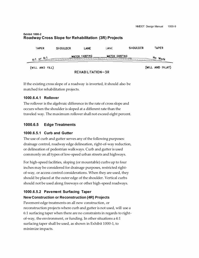
Exhibit 1000-2
Roadway Cross Slope for Rehabilitation (3R) Projects
If the existing cross slope of a roadway is inverted, it should also be
matched for rehabilitation projects.
1000.6.4.1 Rollover
The rollover is the algebraic difference in the rate of cross slope and
occurs when the shoulder is sloped at a different rate than the
traveled way. The maximum rollover shall not exceed eight percent.
1000.6.5 Edge Treatments
1000.6.5.1 Curb and Gutter
The use of curb and gutter serves any of the following purposes:
drainage control, roadway edge delineation, right-of-way reduction,
or delineation of pedestrian walkways. Curb and gutter is used
commonly on all types of low-speed urban streets and highways.
For high-speed facilities, sloping (or mountable) curbs up to four
inches may be considered for drainage purposes, restricted right-
of-way, or access control considerations. When they are used, they
should be placed at the outer edge of the shoulder. Vertical curbs
should not be used along freeways or other high-speed roadways.
1000.6.5.2 Pavement Surfacing Taper
New Construction or Reconstruction (4R) Projects
Pavement edge treatments on all new construction, or
reconstruction projects where curb and gutter is not used, will use a
6:1 surfacing taper when there are no constraints in regards to right-
of-way, the environment, or funding. In other situations a 4:1
surfacing taper shall be used, as shown in Exhibit 1000-1, to
minimize impacts.
1000-10 Geometrics
Rehabilitation (3R) projects
Pavement surfacing tapers on mill and inlay projects are typically
not affected as this process does not encroach into the taper area
and therefore the existing surfacing taper will not be modified.
Pavement surfacing tapers on 3R construction and mill and fill
projects that do encroach into the surfacing taper will use a
6:1 surfacing taper when there are no constraints in regards to
right-of-way, the environment, or funding. In other situations a
4:1 surfacing taper shall be used, as shown in Exhibit 1000-2, to
minimize impacts.
1000.6.6 Side Slopes
Side slopes should be designed to enhance roadway stability and
provide a reasonable opportunity for recovery for a vehicle
departing the roadway. Side slopes will primarily be determined
based on right-of-way availability, roadside drainage, and clear
zone requirements. In general the NMDOT uses a slope of 6:1 for
the foreslope immediately adjacent to the roadway shoulder. For
moderate heights, steeper slopes up to 3:1 may be used. A
maximum side slope of 2:1 is typically used for non-stabilized
slopes. A non-stabilized side slope steeper than this must be
evaluated with regard to soil stability and erosion potential.
Slopes steeper than 2:1 (in both cut and fill conditions) are
permitted when stabilized with riprap or other material. It may not
always be possible or economical to provide flatter side slopes. In
these instances, the typical practice for NMDOT projects is to
specify a depth-variable slope selection criteria in the plans. An
example is provided below:
Depth Maximum Allowable Slope
0 to 5 feet 6:1
5 to 10 feet 4:1
Over 10 feet 3:1
Barn roof sections can also be used in certain fill slope situations.
Barn roof sections consist of a flatter foreslope to the required clear
zone distance and a steeper fill slope to intersect with the existing
ground.

NMDOT Design Manual 1000-11
1000.6.7 Roadside Elements
The guidelines above for surfacing tapers and side slopes do not
preclude the need for the designer to assess clear zone and side
slope treatments beyond the surfacing taper in accordance with the
Roadside Design Guide. The designer should refer to the Roadside
Design Guide for detailed information on clear zone and guidance
on the use of roadside barriers.
1000.7 Intersection Geometrics
NMDOT’s SAMM shall be used for geometric design criteria
pertaining to access points (intersections and turnouts), on a state
facility. The SAMM contains requirements and guidance for access
spacing, suggested design vehicles, sight distance, speed change
lanes, and median design for access points, among other criteria.
1000.8 Documentation
Traffic count data
Calculations
Design exceptions and variances (if needed), per Design Manual
Chapter 210