Embed Size (px)
DESCRIPTION
Â
Citation preview

TVA
Operations Continuing Training
Tennessee Valley Authority
TVA
Ingersoll Rand Sierra Compressor

2 Ingersoll Rand Sierra Compressor
Table of Contents TABLE OF CONTENTS ..................................................................................................................
STUDENT OBJECTIVES .............................................................................................................. 3
Airflow Circuit .................................Airend ................................
................................................................................................................................................................4 ................................................................................................................................................................................ 17
Compression Process............................................................................................................................................................................22 ubrication.................................................................................................................................................................................................LI
25 ntellisys..................................................................................................................................................................................29
........................................................................................................................................................

3 Ingersoll Rand Sierra Compressor
Student Objectives
To review the components of the Pall Filter H
LP22....................................................................
....
Air Flow Circuit
To review the correct operation of the Pall Filter HLP22........................................................... To understand the oil flow path of the Pall Filter HLP22............................................................. To understand the air flow path of the Pall Filter HLP22........................................................... To identify the major and minor alarms associated with the Pall Filter HLP22................... To be able to bring up and review the alarm history for the Pall Filter HLP22....................

4 Ingersoll Rand Sierra Compressor
hen e inlet control butterfly valve is open air enters the 1st Stage Airend and is ompressed to 26-31 PSIG. The air discharges from the Airend via a venturi used to issipate pressure pulsation. Air then moves from the venturi through the 1st stage
a
2nd Stage Airend into a venturi then the air passes through an expansion joint, this allows some of the turbulence and noise to dissipate. The air then continues to the after
W thcd
expansion joint and enters the intercooler where it is cooled to 11 degrees centigrade above ambient temperature. Air exits the intercooler through stainless steel piping to moisture separator (epoxy coated internals). Condensate is removed before the air goes to the 2nd Stage Airend. The air exits the

5 Ingersoll Rand Sierra Compressor
ooler. There is a check valve to prevent air from back flowing into the 2nd Stage Airend. It is tted on the after cooler inlet piping. The air temperature is lowered to within 11 degrees entigrade of the ambient air temperature before exiting through a stainless steel pipe, into a
cficmoisture separator. The air then flows to the desiccant dryers then to the control air system. There is a blow down silencer to reduce noise levels during unloaded operation.

6 Ingersoll Rand Sierra Compressor
nlet Filter I The inlet o the first stage Airend. The filter is 99.5% efficient at (10) micr
filter cleans the air prior ton.

7 Ingersoll Rand Sierra Compressor
Inlet alve V
Stop Nut Unloading Valve
Counter Nut
Blowdown Valve Plate
Butterfly Valve
Butterfly Valve Casing
Compression Springs
Control Cylinder
Control Piston
Needle Screws

8 Ingersoll Rand Sierra Compressor
e Inlet Valve Assembly.
.
These are actual pictures of th
Inlet Butterfly Valve Blow off Valve
Operating Cylinder Inlet Valve Assembly

9 Ingersoll Rand Sierra Compressor
his is a side view of the first stage, it ompresses to 28-41 PSIG
his is a picture of the ont of the First Stage ischarge Venturi.
Tc TfrD

10 Ingersoll Rand Sierra Compressor
he flexible piping is made of corrugated stainless steel with exterior stainless steel raiding. This allows for expansion and misalignment during operation.
Tb

11 Ingersoll Rand Sierra Compressor
he intercooler ools the air prior the inlet of the econd Stage irend. The First tage cooler ools the air to 5.3 degrees
e
is
he purpose of the intercooler oisture separator is to collect
e
TctoSASc1Fahrenheit abovthe ambient temperature on water cooled machines. The Second Stagecooler cools the2nd stage discharge before the air is discharged fromthe compressor.There is a relief valve that is set at 45 pounds per square inch that is not shown in thpicture. There is a stainless steel pipe to the moisture separator. Tmany moisture prior to the secondstage Airend. It is specially designed with an epoxy coating on the interior to prevent rust. The purpose of the Aftercooler Moisture Separator is to removcondensed water from the air stream prior to discharge to the dryer.
First Stage Intercooler
2nd Stage Aftercooler Moisture Se parator

12 Ingersoll Rand Sierra Compressor
he second stage Airend compresses the first stage pressure of 26 to 31 pounds per quare inch to the rated package discharge pressure. The purpose of the second stage
Tsdischarge venturi is to provide pulsation dampening and silencing of the discharge air.

13 Ingersoll Rand Sierra Compressor
his shows a cutaway of the econd stage venturi
he purpose of the check alve is to isolate the control ir system from the
Ts Tvacompressor; it is a twin flap butterfly type check valve.

14 Ingersoll Rand Sierra Compressor
hese are actual pictures of a ischarge silencer. This shows two pplications of the same device, it’s urpose is to dampen pulsations and
ded
Tdapnoise suppression during unloaoperation.

15 Ingersoll Rand Sierra Compressor
The 1st and 2nd
tage ondensate alves are cated after
s
r
st as a
sCVloeach of the moisture separators asseen on page5 and 6 of thisdocument. Both valves are normally open until the power is applied to the unit. This prevents watefrom standing in the moistureseparator and lines with the unit off. Both valves have Y strainers installed before the valve bodies. The 1 stage Condensate valve also hcheck valve before the strainer to prevent backflow during blowdown. The valves arepiped separately to prevent interstage problems.

16 Ingersoll Rand Sierra Compressor
moisture separator is cated immediately after the
rated uration
.
mpressors are as follows. We have a 250 HP motor st nd
Alointercooler and the aftercooler to collect any condensation from the compressed air. The condensate is drained through electrically opevalves. The opening dof the condensate valves is preset at three seconds and is adjustable between 2 to 20 seconds. The opening between these intervals may be adjusted between 60 and 360 seconds, depending on the ambient temperature. If the environment consists of high temperature and or high humidity, then the interval may have to be reduced to facilitate moisture removal. The factory setting is 180 seconds. To check the operation of the solenoid valves, you should open the manual bypass valves momentarily once per day to check for moistureFor extended shutdown periods, the manual valves should be left open to prevent the accumulation of moisture. Strainers are provided upstream of the condensate valves to prevent any particles from plugging the solenoid valves. Before any maintenance is performed on the strainers or the solenoid valves, the strainer service valves should be closed, in order to isolate them from possible high pressure. The Safety Valve settings for our coso the 1 stage is set at 55psig and the 2 stage is set at 165psig.

17 Ingersoll Rand Sierra Compressor
Airend
An Airend is the part of the compressor that produces the ompres
t
1st
Stage c sed air. Rotary compression and displacemenis achieved by the positive action of the rotating elements in the Airend. 2nd Stage

18 Ingersoll Rand Sierra Compressor
he air to be compressed enters the compressor through an opening at the right end of e enclosure. The air travels through a passageway lined with sound absorbing aterial to the air filter. It then travels through a round flexible hose, the air passes
Tthmthrough the inlet valve assembly into the first stage of the compressor.

19 Ingersoll Rand Sierra Compressor
crew dry compressors operate on the positive air isplacement principle in a similar way as contact ooled rotary compressors do (Sullair). One shaft tates both rotors. Oil injection keeps them
n
o
rotors to ensure perfect running.
Sdcrolubricated and cool just as in the Sullair compressors. Inside the screw compressor casing there are two rotors which rotate in opposite directions. The rotors have specially shaped profile lobes which are helically twisted ian axial direction, comparable to a helically toothed pair of gear wheels. The number oflobes in the 1st stage is: the male rotor has 3 lobes and the female rotor has 4 lobes. The number of lobes in the 2nd stage is: The male rotor has 4 lobes and the female rotor has 6 lobes.
Any contact between the rotors is prevented by a pair of timing gears arranged outside the compression chamber. The radial and axial clearances between the
tors and therocasing are alsvery low. Therefore, forincreased safety, small projections
have been provided on the profile diameter and on the discharge side face ends of the
20 Ingersoll Rand Sierra Compressor
he helical rotors compress the ir to a pressure of between 25 38 psig. The air is discharged to a venturi, which dampens ny pressure pulsations that ay be present before entering e intercooler.
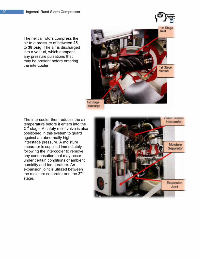
he intercooler then reduces the air mperature before it enters into the
nd stage. A safety relief valve is also ositioned in this system to guard gainst an abnormally high terstage pressure. A moisture
eparator is supplied immediately llowing the intercooler to remove
Tatoinamth Tte2painsfoany condensation that may occur under certain conditions of ambient humidity and temperature. An expansion joint is utilized between the moisture separator and the 2nd
stage.

21 Ingersoll Rand Sierra Compressor
he 2nd stage further ompresses the air the desired ressure. The ressure pulsations re dampened by the nd stage venturi.
s to
int is valve
Tctoppa2There is an expansion joint to prevent transmition of any vibrationthe air system. A wafer type check valve is provided to prevent any back flow of air into the compressor. The Aftercooler cools theair to a suitable temperature, while the discharge moisture separator removes significant amounts of condensation. When the desired pressure po
ached, the inlet butterflyrecloses. As the butterfly inlet valve closes the hydraulic cylinder opens the blowdown valve to unload the compressor. The actuator (Hydraulic Cylinder), which opens and closes the inlet, unloading valves, is connected to the lubricating system through the 1SV solenoid valve.

22 Ingersoll Rand Sierra Compressor
ssion Process The Compre
s, air is drawn into the pockets between the malobpo
h
nt rust. Sierra Module bearing
pes include: 4 roller bearings at the )
As rotation of the compressor beginle rotor lobes and the female rotor es. The compression process for the sitive displacement group of
the compressors depends upon reducingvolume of a given amount of air, whicthereby increases the air pressure. With further rotation, the leading strip of the male lobe reaches the contour of the female groove and traps the air in the pocket previouslyformed. The air is moved down the female rotor groove and is compressed as the volume is reduced. When the male rotor lobe reaches the end of the groove, the trapped air is discharged from the Airend. The Airend bearings position the rotor in the center of the Airend housing and prevent rotor movemedue to thtyInlet and Discharge and 2 (4 pointaircraft type thrust bearings.

23 Ingersoll Rand Sierra Compressor
his is the arrangement of the Airend parts we have vered. This is the 2nd stage Airend.
he labyrinth seals perform the task of preventing oil
free dry air.
Tco Tfrom the lubricating system from getting into the compression zone of the Airend. This is a critical component if we are to maintain oil

24 Ingersoll Rand Sierra Compressor
ent holes are supplied to nable us to monitor the ondition of the labyrinth seals. y feeling the discharge from ese vent holes we can etermine if there is any
idue
VecBthdleakage through the seals. There should not be any reson your fingers. First Stage Vent Holes Second Stage Vent Holes

25 Ingersoll Rand Sierra Compressor
Lubrication
The lubrication system is suppli il performs the following
nctions: 1. Lubrication of the bearing
2. Housing Cooling
3. Operation of the Inlet/ Bl
ed by the Oil Pump. This o
s
ow-off Valve
fu

26 Ingersoll Rand Sierra Compressor
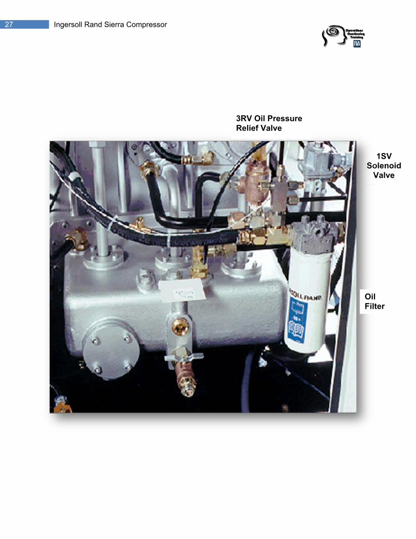
The oil is drawn through a suction strainer, which is used to filter out large contaminants. The oil proceeds to the suction port on the oil pump and then elevated in pressure to approximately 40 to 60 PSIG. There is a pressure relief valve on the oil pump discharge piping to relieve oil to the sump. This is factory set at 100 PSIG. The oil is discharged to the oil cooler where it’s cooled to approximately 54 to 60°C. A thermally controlled mixing valve is located on the cooler outlet. This valve mixes hot oil, (which bypasses the cooler) and cool oil from the cooler to maintain optimal oil temperature of 54 to 60°C. The oil leaves the thermal mixing valve and proceeds through a 10micron filter, and then is diverted to multiple oil feed points on the two Airends. Pressurized oil is also supplied to the 1SV solenoid valve. It operates the hydraulic cylinder used to load and unload the unit. The oil that has been fed to the bearings is drained from Airends via the oversized drain ports located on the bottom side of the Airends. The oil pressure is controlled by the use of an orifice, sized by the factory located in the oil outlet piping on the 2nd stage Airend housing. The oil level should be maintained at three quarters full with the compressor running.
Orifice
3RV
27 Ingersoll Rand Sierra Compressor
1SV Solenoid
Valve
3RV Oil Pressure Relief Valve
Oil ilter F

28 Ingersoll Rand Sierra Compressor
he reather eparates il mist om the earcase apor. It
the plenum area. The wire wool filter should be cleaned every 2,000 hours.
TBsofrgvvents into

29 Ingersoll Rand Sierra Compressor
Intellisys
The SG Insystem is Ingersoll-Rdevelopedcompresmicroprocecontroller umembranethe comprecontrol parInformatioperation a Liq
om a
tellisys control an exclusive and design, for reliable
sor operation. The ssor-based ses a finger touch for operation of ssor and setting ameters.
on about the current ng status is available uid Crystal Display
list of temperature, ressure and filter condition readings. The Intellisys monitors the compressor and hould any pre-programmed limit be exceeded, the controller automatically displays a arning or issues an alarm to shut the compressor down. group of pressure and temperature sensors, relays and switches support the decision aking process.
frpswAm

30 Ingersoll Rand Sierra Compressor
he Start Button will start the compressor if the display shows Ready to Start. The ompressor will start and load if there is sufficient demand for air. The Stop Button will ctivate the unloaded stop sequence. If the compressor is running loaded, it will nload and continue to run unloaded for an adjustable 10 to 30 seconds and then stop. the compressor is running unloaded and the button is pressed, it will stop mediately. The Unload Button will cause the compressor to unload and remain
nloaded. This display will indicate the machine is Running Unloaded, and Mode: nload. The Load Button will cause the compressor to load if the machine has been tarted and the Discharge Pressure is less than the Online Pressure. The Up and own Arrow Buttons have multiple functions relating to the right half of the screen. hen lists are presented, the buttons are used to move up and down through the items
n the list. The Small Arrows displayed in the upper right corner of the display screen dicate when you can move up (designated by the arrow head pointing up) and/or own (designated by the arrow head pointing down) through the list. The functions of e Display Buttons change and are defined by the words immediately above them in e bottom line of the screen. Such as Main Menu, Status Set etc......
Arrows
Small Arrows
ButtonsDisplay
Start Stop Unload Load
TcauIfimuUsDWoindthth

31 Ingersoll Rand Sierra Compressor
hen warning occurs, the word Warning will flash on the screen in large letters. The isplay message would indicate what calls the warning and the reset button appears. A nning compressor will continue to run and provide air during a warning. If multiple arnings exist, the small up and down arrows will appear in the upper right corner of the
w
se r.
Warning
Wdruwdisplay screen. The multiple warnings can be seen by pressing the up and down arrobuttons. Press and status button will display the Current Status screen. The status button changes to a warning button indicating other warnings still exists. The reset button disappears at this time. Use the up and down arrows to observe the current status items associated with the warning in the display. Pressing the warning button will return the display to the warning screen and the reset button returns. When the caufor the warning has been corrected, press the reset button twice to clear the controlleA warning remains on the screen until it is reset by an operator. Warnings are:
• Change Coolant Filter • Change Inlet Filter • Sensor Failure

32 Ingersoll Rand Sierra Compressor
hese are the warnings listed again with their causes:
hange Coolant Filter: This warning will occur at the press differential across the coolant filter exceeds 13 psi and the bearing oil temperature is greater than 110°f. Change Inlet Filter: This will occur in the inlet vacuum (1 AVPT) is greater than 0.7 PSI and the compressor is fully loaded with the inlet valve in the fully open position. Sensor Failure: This will occur if the Intellisys recognizes a missing or broken sensor, sensors affected by this warning are 50PT, 3ATT and 7ATT. The failed sensor will be displayed along with the sensor failure message.
T C

33 Ingersoll Rand Sierra Compressor

34 Ingersoll Rand Sierra Compressor
When an alarm occurs, the word ALARM in large capitals will appear and the display message will indicate what caused the alarm and the Reset Button will appear. A compressor that is running will be shutdown immediately as an ALARM situation arises, causing the Remote Alarm Contacts to change state. The compressor cannot be restarted either manually or automatically, until the Alarm situation has been rectified and the Intellisys Controller reset. An already stopped compressor cannot be started if an Alarm condition exists. Pressing the Status Button will activate the ALARM STATUS screen with the ALARM Button indicating an alarm situation still exists. Alarm status gives a list of operating parameters of the compressor when the ALARM occurred. The value of the parameters can be seen by scrolling using the arrow buttons, pressing the ALARM Button will return to the alarm screen and bring back the RESET BUTTON. The ALARM can be reset by pressing the RESET Button, when the ALARM condition has been rectified. Remember an Alarm will cause the immediate shutdown of the compressor.
ALARM

35 Ingersoll Rand Sierra Compressor
change e selection. There is small arrow prompt within the display indicating which of the two uttons to use. The Y prompt is for the UP button and the B prompt is for the Down utton. The C prompt indicates the current status display is somewhere in the middle nd either the UP or the Down button can be used.
Any of the Current Status readings selected will remain on the display until another status item is chosen. Use the UP or Down buttons at the right of the display to thbba

36 Ingersoll Rand Sierra Compressor
perator Setpoints are user adjustable settings in the controller logic that can be hanged using the Operator Setpoints Screen. Changes to the Operator Setpoints an be made while the compressor is in operation. The Operator Setpoints listed bove can be seen on the screen by moving the UP and DOWN arrow buttons. The ETPOINT Value can be changed by highlighting the item and its value and pressing e Select Button to highlight just that value. When the value is highlighted it can be
ar
t
either the STATUS or MAIN ENU buttons. If no buttons are pressed within 30 seconds, the display automatically turns to the CURRENT STATUS screen showing PACKAGE DISCHARGE
EMPERATURE and 1st Stage.
Operator Setpoints OccaSthadjusted by using the UP and DOWN arrows. The CANCEL and SET Buttons appeat this time. Press the SET Button to enter the new value, or press the CANCEL Button to return the value to the setpoint prior to using the arrows. The displayed value will flash twice to indicate it has been entered into the setpoint, and the pair of setpoinitems and value display will again be highlighted together. OPERATOR SETPOINTS can be exited by pressingMreT

37 Ingersoll Rand Sierra Compressor
Operator Setpoint Descriptions
ead/Lag- will control the compressor at the Off/On Line values programmed. The Lag election will control the compressor at the Off/ ON Line values. FFLINE PRESSURE- the pressure at which the compressor will unload. NLINE PRESSURE- the pressure at which the compressor will re-load. ag Offset- reduces OFF/ON Line values when Lag is selected. oad Delay Time- the time delay period between tchieved and the actual loading of the compressor.
d
te
d
LsOOLL he ON Line pressure set point aCondensate Release- the time period that the condensate solenoid valves 6SV an9SV open. CONDENSATE INTERVAL-the time period between the operation of the condensasolenoid valves 6SV and 9SV when the compressor is running loaded. STAR/DELTA- determines the period of time before delta transition. (refer to manual) MAX 1ST STAGE TEMPERATURE- an adjustable set point depending on the rated pressure of the unit, and is factory set to the maximum. MAX 2ND STAGE TEMPERATURE- an adjustable set point depending on the ratepressure of the unit, and is factory set to the maximum. DISPLAY CONTRAST- controls the LCD display brightness.

38 Ingersoll Rand Sierra Compressor
he Clock Function allows the contr ions. Such as
Ts
oller to perform real time control functcheduled Start and Stop.

39 Ingersoll Rand Sierra Compressor
Pressure Sensor Descriptions: 1AVPT – Inlet Vacuum
or having a range between 0 and 15 psi vacuum connected to the Airend inlet ation to
th correct position for both loaded and unloaded operation. It will lso indicate the condition of the inlet air filter for the Intellisys to monitor and warn when ecessary.
ge Discharge Pressure and 3 APT – 2nd Stage Discharge Pressure he Airend discharge is monitored for several reasons to include comparison to line pressure uring separator element differential check and to provide logic for the controller to position the let valve during unloaded operation. The normal unloaded intercooler pressure is maintained t 0 PSI and loaded within a range of 26 to 31 psi to ensure adequate inlet pressure to the 2nd tage to prevent over ratio of the 2nd stage Airend. The normal unloaded 2nd stage discharge ressure is maintained at 0 PSI and loaded to the rated pressure of the machine. This pressure monitored as the unit unloads to ensure the 2nd stage Airend discharge has blown down to tmosphere ensuring that any over ratio situation is detected and the unit stops in an alarm ondition.
A pressure sensto provide vacuum information for the controller. The controller uses inlet vacuum informconfirm the inlet valve is in e an 2 APT – 1st StaTdinaspisac

40 Ingersoll Rand Sierra Compressor
4APT-Package Discharge Pressure This sensor is used to provide information about the discharge pressure just prior to the compressed air leaving the package. The connection is downstream of the Aftercooler and in the top of the moisture separator. Package discharge pressure provides logic to load or unload the compressor. 5OPT- Oil Filter Inlet Pressure and 6OPT- Oil Filter Outlet Pressure Two (2) pressure sensors are used to monitor the lubricant filter differential and the lubricant pressure is monitored continually to ensure that the bearings have a continuous feed of lubricant.

41 Ingersoll Rand Sierra Compressor
emperature Sensors and Descriptions-- 2ATT, 3ATT, 4ATT, 5OTT, 7ATT
emperature sensors are used to monitor temperature changes at various points within the ompressor package. They operate on a 12 V DC circuit. As the temperature of the sensor hanges either higher or lower, the resistance to the sensor changes a corresponding amount. s the output voltage varies due to the temperature changes, the voltage strength is processed y an analog-to-digital converter within the controller. Depending on the output voltage from the arious sensors, the controller makes decisions that may change a number on the panel isplay, delay a differential pressure reading until the compressor warms up, reposition the inlet alve slightly doing cold unloaded operation, provide WARNING about rising temperature or ould possibl ditions dictate.
T TccAbvdvc y shut the compressor down with an ALARM if operating con

42 Ingersoll Rand Sierra Compressor
Alarm Messages
• Sensor Failure 1AVPT (Inlet Vacuum) • Sensor Failure 2APT (2nd Stage Inlet Pressure) • Sensor Failure 3APT (2nd Stage Discharge Pressure) • Sensor Failure 4APT (Package Discharge Pressure) • Sensor Failure 6OPT ( Bearing Oil Pressure) • Sensor Failure 2ATT (1st Stage Discharge Temperature) • Sensor Failure 4ATT (2nd Stage Discharge Temperature) • Sensor Failure 5 OTT (Bearing Oil Temperature)
All of the shown sensor failure alarm will cause compressed the shutdown if that sensor is detected by the Intellisys controller to be missing or broken. Causes can be:
• A broken wire • A bad transducer • There can be moisture in the transducer or in a temperature sensor.
Check Setpoints: This alarm will only occur at power up. It is an indication that some of the Setpoints in the controller out of range and Intellisys reloaded it’s the default values. Invalid Calibration This alarm will only occur doing calibration. An invalid calibration alarm is normally an
dication of pressure already being on the sensor. • Bad Transducer • Pressure on the System • Plastic tubing still connected to the transducer.
in
mergency Stop EThis alarm is an indication that the emergency stop button has been pressed. Check Control Power/Phase This alarm occurs when the 120 V AC power (connection at P1 – 1) is lost. Cause:
• A bad control transformer • Phase monitor malfunction
43 Ingersoll Rand Sierra Compressor
tarter Fault 1SL (2SL) his alarm occurs if the auxiliary contact on 1M (1SL) or 1S and 2M (2 SL) is closed and start is attempted on th
Cause: • The auxiliary conta• EPROM rev 1.5 and above will not display this alarm • A loose wire.
in motor has opened. This alarm is issued. Cause – check
fan motor has opened. This
f the set point in the options menu called condensate level intercooler condensate level switch closes for at least 60
t
reater than 43 PSI, and the 1st stage discharge temperature is greater than 410°F. If running unloaded this alarm with occur if the 2nd stage Inlet pressure
r coating
STa e compressor.
cts bad
Main Motor Overload This alarm indicates that the motor overload switch to the macondition must exist for at least 3 seconds before themotor current at full load. Fan Motor Overload
his alarm indicates that the motor overload switch to theTcondition must also last at least 3 seconds.
sate High I/C CondenThis al arm will occur iinstalled is set to On andseconds. Cause – check the intercondenser drain for proper operation. Inlet Restriction This alarm will occur in the inlet vacuum is greater than 13.3 PSI. This alarm will also occur if the compressor is running and has been loaded for at least 8 seconds, and inleacuum is greater than 3 PSI. v
Cause: • Check the inlet filter • Check for collapsed hoses
High Intercooler Pressure This alarm will occur if the compressor is loaded and the 2nd stage Inlet pressure is gthe compressor is is greater than 10 PSI. The unloaded alarm will only be checked during the 1st 7 seconds of operation. Cause:
• Remove the 2nd stage Inlet tubing and view the male and female rotoeview the intercooler tubing for rust in the cooler bonnet. • R
• Clean the intercooler.

44 Ingersoll Rand Sierra Compressor
igh 2nd Stage Pressure his will occur if the compressor is running and the 2nd stage discharge pressure is reater than 15 PSI above rated pressure. ause: • The pressure sensor is out of calibration. • There could be electrical noise affecting the sensor.
e transducer location.
ow Bearing Oil Pressure or this alarm to occur the compressor must be running and the oil pressure is less than
t checked until the compressor has been running at least 7
e could be out of adjustment.
ur if the unit is running and the 1st stage discharge temperature is g
charge temperature set point by 20°F. Cause- The high.
HTgC
High Line Air Pressure This will also occur if the compressor is running and the package discharge pressure is greater than 15 PSI above the rated pressure. Cause:
• Review the remote pressur• Check the transducer calibration.
LF34 PSI. This alarm is noseconds and this alone will not be checked the first 8 seconds after the compressor loads. If the oil pressure falls below 34 PSI, there’ll be a 2 second time delay before thealarm comes in. Cause:
• Incomplete start Delta transition. • The auxiliary contacts could malfunction. • A low oil level. • The oil relief valv• The oil pump could be bad.
igh 1st Stage Temperature HThis alarm will occgreater than the high 1st stage discharge temperature set point or the unit is not runninand the 1st stage discharge temperature is greater than 95% of the high 1st stage discharge temperature set point. In both cases, the 1st stage discharge temperature
xceed the 1st stage discannot eamb eni t temperature is too

45 Ingersoll Rand Sierra Compressor
Stage Temperature
r the unit is not charge temperature is greater than 95% of the high 2nd
tage discharge temperature set point. In both cases, the 2nd stage discharge mperature cannot exceed the 2nd stage discharge temperature set point by 20°F. ause- The ambient temperature is too high
igh I/C Air Temperature running and the 2nd stage Inlet (intercooler) temperature is
heck the 2nd stage male and female rotor coatings. bonnet.
n
erating in this mode for at least 20 This alarm will occur after a Load or Stop Unit Warning.
High 2ndThis alarm will occur if the unit is running and the 2nd stage discharge temperature is greater than the high 2nd stage discharge temperature set point orunning and the 2nd stage dissteC HThis occurs when the unit isgreater than 140°F. Cause:
• C• Check the intercooler tubing for rust on the• Clean the intercooler
Excessive Unloaded RuThis alarm will occur if the operator has to unload the compressor by pressing the unload button and the compressor has been opminutes.