Embed Size (px)
Citation preview

Siemens WT 10 · 2018
33/2 Introduction
3/3 Mounting components3/3 Introduction
3/4 Single point load cells3/4 Overview3/5 SIWAREX WL260 SP-S AA3/5 - Load cell3/6 SIWAREX WL260 SP-S AB3/6 - Load cell3/7 SIWAREX WL260 SP-S AE3/7 - Load cell3/8 SIWAREX WL260 SP-S SA3/8 - Load cell3/10 SIWAREX WL260 SP-S SB3/10 - Load cell3/12 SIWAREX WL260 SP-S SC3/12 - Load cell
3/14 Bending beam load cells3/14 Overview3/15 SIWAREX WL230 BB-S SA3/15 - Load cell3/17 - Mounting unit3/19 - Elastomer bearing3/20 - Base plate
3/21 Shear beam load cells3/21 Overview3/22 SIWAREX WL230 SB-S SA3/22 - Load cell3/24 - Mounting unit3/26 - Base plate with elastomer bearing3/28 SIWAREX WL230 SB-S CA3/28 - Load cell
3/30 Double shear beam load cells3/30 Overview3/31 SIWAREX WL290 DB-S CA3/31 - Load cell3/33 - Mounting unit for vehicles
3/34 S-Type load cells3/34 Overview3/35 SIWAREX WL250 ST-S SA3/35 - Load cell
3/37 Compression load cells3/37 Overview3/38 SIWAREX WL270 CP-S SA3/38 - Load cell3/40 - Mounting unit and guide element3/43 - Pressure piece set and adapter plates3/44 SIWAREX WL270 CP-S SB3/44 - Load cell3/46 - Mounting unit3/47 SIWAREX WL270 CP-S SB3/47 - Pressure piece set3/48 SIWAREX WL270 K-S CA3/48 - Load cell3/53 SIWAREX WL270 K-S CA3/53 - Self-aligning bearing
3/55 Ring torsion load cell3/55 Overview3/56 SIWAREX WL280 RN-S SA3/56 - Load cell3/64 - Mounting unit and guide element
3/66 Load cell accessories3/66 Junction box SIWAREX JB3/68 Extension box SIWAREX EB3/70 Cables
3/71 Configuration examples3/71 Introduction3/72 Configuration example 13/73 Configuration example 23/74 Configuration example 3
Load Cells
WT10-2018_en_Kap03.book Seite 1 Dienstag, 5. Juni 2018 11:50 11
© Siemens AG 2018

3/2 Siemens WT 10 · 2018
Load CellsIntroduction
3
■ Overview
Siemens offers load cells in the SIWAREX WL200 series. All load cells are equipped with strain gauges. They are used for static and dynamic weight measurements.
The different load cell series cover rated loads from 0.3 kg (0.661 lb) to 500 t (492.103 tn. L.).
The variety of modules available and their characteristics, in-cluding• predominantly stainless steel for high anti-corrosion protection • predominantly hermetically sealed housing for use even in
hostile or corrosive environments • compact modules for easy installation
make SIWAREX load cells suitable for virtually all applications in industrial weighing, e.g. hopper scales and bin weighing equip-ment, platform weighing machines, vehicle scales, hybrid scales etc.
Almost all series have been approved for use with Class III legal-for-trade commercial scales in accordance with EN 45501 and conform to OIML R60.
Of course, load cells can also be supplied for other rated loads, higher accuracy, and/or Ex approval, depending on require-ments.
■ Design
Load cells are sensors that convert a mechanical variable (i.e. weight) into an electrical signal, usually a voltage.
They work with different measuring principles. Siemens load cells in the SIWAREX WL200 series use so-called strain gauges. These are specially formed electrical conductors which are insu-lated by means of a suitable material. The strain gauges are at-tached to the basic element, a specially formed spring body, by friction locking.
Under the influence of a weight force F, the spring body is de-formed (see schematic presentation) and as a result the strain gauge deforms elastically. Due to the change in the external shape of the strain gauge, the ohmic resistance of its conductor also changes. The top left and bottom right strain gauges are compressed, their resistance films are shortened and the ohmic resistance is reduced accordingly. The top right and bottom left strain gauges are stretched, their resistance films are extended and the ohmic resistance is increased.
For each load cell, at least four strain gauges are connected to-gether to form a complete Wheatstone bridge. The stretched or compressed strain gauges are connected so that the positive or negative resistance changes are added together to form a total imbalance in the bridge.
On one bridge diagonal, the power voltage is applied (with 6-conductor technique, also the sensor voltage, SENSE) and on the other diagonal, the measured voltage is tapped.
With a constant power voltage (EXC), the measured voltage (SIG) changes proportionally to the introduced load.
Principle of a bending load cell, loaded
Principle of a Wheatstone bridge
compressed SG
stretched SG
compressed SG
stretched SG
F
SG stretched
SG compressed
SG compressed
SG stretched
G_W
T01_
XX
_100
91EXC+
SIG- SIG+
SENSE+
SENSE-EXC-
WT10-2018_en_Kap03.book Seite 2 Dienstag, 5. Juni 2018 11:50 11
© Siemens AG 2018

3/3Siemens WT 10 · 2018
Load CellsMounting components
Introduction
3
■ Overview
The use of SIWAREX WL200 installation accessories avoids in-correct loading such as eccentric load introduction, torsion torques etc. on the load cells. enables full exploitation of the measuring accuracy of the load cells.
The standardized SIWAREX WL200 installation components are always coordinated precisely to the requirements of the respec-tive load cell design. This ensures that the force to be measured is directed to the load cells in the best possible way.
At the same time the mounting elements simplify the installation of the load cells and increase safety during installation work. The wide variety of mounting components permits implementation of all key applications used with industrial weighing technology. In addition to the mounting components listed below, a wide range of special accessories is available for special requirements.
WT10-2018_en_Kap03.book Seite 3 Dienstag, 5. Juni 2018 11:50 11
© Siemens AG 2018

3/4 Siemens WT 10 · 2018
Load CellsSingle point load cells
3
■ Overview
1 2
Type Single point
Possible applications
Small platform scales, small conveyor scales
Example picture
Series WL260 SP-S AA WL260 SP-S AB WL260 SP-S AE
Rated load Emax 3 ... 100 kg (6.61 ... 220.46 lb)
50 ... 500 kg(110.23 ... 1 102.31 lb)
0,3 kg ... 3 kg(0.66 ... 6.61 lb)
Accuracy class C32) C31) 0.015 %
Max. load cell verifi-cation interval (nIC)
3 000 3 000 3 000
Min. load cell verifi-cation interval (Vmin)
Emax/12 000 Emax/10 000 k. A.
Supply voltage (Usr) 5 ... 12 V 5 ... 12 V 6 ... 12 V
Rated characteristic value
2 mV/V 2 mV/V 0,9 mV/V
Degree of protection IP65 IP65 IP65
Material Aluminum Aluminum Aluminum
Ex protection according to ATEX (optional)
- - -
Type Single point
Possible applications
Platform scales, small conveyor scales
Example picture
Series WL260 SP-S SA WL260 SP-S SB WL260 SP-S SC
Rated load Emax 5 ... 200 kg(11.02 ... 440.92 lb)
6 ... 60 kg(13.23 ... 132.28 lb)
10 ... 500 kg(22.05 ... 1 102.31 lb)
Accuracy class C3 C3 C3, C3 MR, C4 MR
Max. load cell verifi-cation interval (nIC)
3 000 3 000 3 000
Min. load cell verifi-cation interval (Vmin)
Emax/9 000 Emax/15 000 Emax/10 000 with C3Emax/20 000 with C3 MREmax/40 000 with C4 MR
Supply voltage (Usr) 5 ... 12 V 5 ... 12 V 5 ... 12 V
Rated characteristic value
2 mV/V 2 mV/V 2 mV/V
Degree of protection IP67 IP68 IP68, IP69K
Material Stainless steel Stainless steel Stainless steel
Ex protection according to ATEX (optional)
II1 G EX IA IIC T4II1 D EX IAD 20 T73GRAD C II 3G EX NL IIC T4
- -
1) OIML type approval for SIWAREX WL260 SP-S AB types available soon.2) Available in C4 with Y = 20 000 upon request.
WT10-2018_en_Kap03.book Seite 4 Dienstag, 5. Juni 2018 11:50 11
© Siemens AG 2018
3/5Siemens WT 10 · 2018
Load CellsSingle point load cells
SIWAREX WL260 SP-S AA
Load cell
3
■ Overview
The load cell is suitable for small platform scales with one load cell (max. platform size 400 x 400 mm (15.75 x 15.75 inch)) as well as for use in medium accuracy weighing machines of Class III with a max. scale verification intervals nmax = 3000d.
■ Design
The load cell is hermetically sealed.
■ Technical specifications
■ Selection and ordering data Article No.
■ Dimensional drawings
SIWAREX WL 260 SP-S AA load cell, dimensions in mm (inch)
SIWAREX WL260 SP-S AA
Possible applications • Platform scales
• Small belt scales
Model Single point load cell
Loads
Rated load Emax • 3 kg (6.61 lb)• 5 kg (11.02 lb)• 10 kg (22.05 lb)• 20 kg (44.09 lb)• 50 kg (110.23 lb)• 100 kg (220.46 lb)
Minimum initial loading Emin 0% Emax
Maximum working load LU 150% Emax
Break load LD 300% Emax
Maximum lateral load Llq 100% Emax
Measurement characteristic values
Rated measuring path hn at Emax < 0.6 mm (0.05 in)
Rated characteristic value Cn 2.0 ± 0.2 mV/V
Tolerance D0 of zero signal < ± 2% Cn
Maximum scale interval nlc 3 000
Min. load cell verification interval Vmin Emax/12 000
Combined error Fcomb ± 0.02% Cn
Repeatability Fv ± 0.017% Cn
Creep error Fcr• 30 min ± 0.02% Cn
Temperature coefficient• Zero signal TKo 0.017% Cn/5 K• Characteristic value TKc 0.014% Cn/5 K
Electrical characteristic values
Recommended reference voltage Uref 5 … 12 V DC
Input resistance Re 409 ± 6
Output resistance Ra 350 ± 3
Insulation resistance Ris 5 000 M at 50 V DC
Connection and environmental conditions
Rated temperature range Btn -10 ... +40 °C (14 ... 104 °F)
Operating temperature range Btu -35 … +65 °C (-31 ... 149 °F)
Storage temperature range Bts -35 … +65 °C (-31 ... 149 °F)
Sensor material (DIN) Aluminum
Maximum tightening torque of the fixing screws
15 ... 20 Nm
Degree of protection to EN 60529; IEC 60529
IP65
Cable connection
Function Color
• EXC + (supply +) red
• EXC – (supply -) black
• SIG + (measured signal +) green
• SIG – (measured signal -) white
• Sense + (sensor line +) blue
• Sense - (sensor line -) brown
• Shield transparent
Certificates and approvals
Accuracy class according to OIML R60
C3
Load cell type WL 260 SP-S AA 7MH5102-
Legal-for-trade according to OIML R60 to 3000d, 3 m connection cable
■ ■ D 0 0
Click on the Article No. for the online configuration in the PIA Life Cycle Portal.
Rated load
• 3 kg (6.61 lb) 1 K
• 5 kg (11.02 lb) 1 P
• 10 kg (22.05 lb) 2 A
• 20 kg (44.09 lb) 2 G
• 50 kg (110.23 lb) 2 P
• 100 kg (220.46 lb) 3 A
SIWAREX WL260 SP-S AA
1
1
1
Threaded hole M6, depth 15 (0.59)1
5.8 (0.23)
5.8 (0.23)
38.6
(1.5
2)
34 (1.34)
150 (5.91)19
(0.75)
25 (0
.98)
11
(0.4
3)
40 (1
.57)
31 (1.22)
19 (0.75)
19
(0.7
5)
WT10-2018_en_Kap03.book Seite 5 Dienstag, 5. Juni 2018 11:50 11
© Siemens AG 2018
3/6 Siemens WT 10 · 2018
Load CellsSingle point load cellsSIWAREX WL260 SP-S AB
Load cell
3
■ Overview
The load cell is suitable for small to medium platform scales with one load cell (max. platform size 600 x 600 mm (23.62 x 23.62 inch)) as well as for use in medium accuracy weighing machines of Class III with a max. verification interval nmax = 3000 d.
■ Design
The load cell is hermetically sealed.
■ Technical specifications1
■ Selection and ordering data Article No.
■ Dimensional drawings
SIWAREX WL 260 SP-S AB load cell, dimensions in mm (inch)
1) OIML type approval for SIWAREX WL260 SP-S AB available soon.
SIWAREX WL260 SP-S AB
Possible applications • Platform scales
• Conveyor scales
Model Single point load cell
Loads
Rated load Emax • 50 kg (110.23 lb)• 75 kg (165.35 lb)• 100 kg (220.46 lb)• 150 kg (330.69 lb)• 200 kg (440.92 lb)• 300 kg (661.37 lb)• 500 kg (1 102.31 lb)
Minimum initial loading Emin 0 kg
Maximum working load Lu 150% Emax
Break load Ld 300% Emax
Maximum lateral load Llq 100% Emax
Measurement characteristic values
Rated measuring path hn at Emax < 1.22 mm (0.05 in)
Rated characteristic value Cn 2.0 ± 0.2 mV/V
Tolerance D0 of zero signal < ± 2% Cn
Maximum scale interval nlc 3 000
Min. scale interval Vmin Emax/10 000
Combined error Fcomb ± 0.02% Cn
Repeatability Fv ± 0.017% Cn
Creep error Fcr• 30 min ± 0.02% Cn
Temperature effect• Zero signal TKo 0.017% Cn/5 K• Characteristic value TKc 0.014% Cn/5 K
Electrical characteristic values
Recommended input voltage 5 ... 12 V DC
Input resistance Re 409 ± 6
Output resistance Ra 350 ± 3
Insulation resistance Ris 5 000 M at 50 V DC
Connection and ambient conditions
Sensor material (DIN) Aluminum
Maximum tightening torque of the fixing screws
35 ... 40 Nm
Rated temperature range Btn -10 ... +40 °C (14 ... 104 °F)
Operating temperature range Btu -35 ... +65 °C (-31 ... +149 °F)
Storage temperature range Bts -35 ... +65 °C (-31 ... +149 °F)
Degree of protection to EN 60529, IEC 60529
IP65
Cable connection
Function Color
• EXC + (supply +) Red
• EXC – (supply -) Black
• SIG + (measured signal +) Green
• SIG – (measured signal -) White
• Sense + (sensor cable +) Blue
• Sense - (sensor cable -) Brown
• Shield Transparent
Certificates and approvals
Accuracy class according to OIML R60
C31)
Load cell, type WL260 SP-S AB 7MH5103-
Connecting cable 3 m (9.84 ft) ■ ■ D 0 0
Click on the Article No. for the online configuration in the PIA Life Cycle Portal.
Rated load
• 50 kg (110.23 lb) 2 P
• 75 kg (165.35 lb) 2 S
• 100 kg (220.46 lb) 3 A
• 150 kg (330.69 lb) 3 E
• 200 kg (440.92 lb) 3 G
• 300 kg (661.37 lb) 3 K
• 500 kg (1 102.31 lb) 3 P
SIWAREX WL260 SP-S AB
1
1
Threaded hole M8, depth 151
7.8 (0.31)
7.8 (0.31)
40 (1.57)
76 (2
.99)
60 (2
.36)
75 (2
.95)
191 (7.52)
25 (0.98)
40 (1.57) 25 (0.98)
WT10-2018_en_Kap03.book Seite 6 Dienstag, 5. Juni 2018 11:50 11
© Siemens AG 2018

3/7Siemens WT 10 · 2018
Load CellsSingle point load cells
SIWAREX WL260 SP-S AE
Load cell
3
■ Overview
SIWAREX WL260 SP-S AE load cell
The SIWAREX WL260 SP-S AE single point load cell is suitable for the smallest load ranges from 0.3 kg to 3 kg and platform sizes up to 200 mm x 200 mm.The load cell can be used in high resolution scales. The error amounts to a maximum of 0.015% in relation to the rated charac-teristic value.
■ Design
The measurement element is a spring body made of aluminum. Due to IP65 degree of protection, the load cell is suitable for cleaning with water jets.
■ Technical specifications
■ Selection and ordering data Article No.
■ Dimensional drawings
SIWAREX WL260 SP-S AE Load Cell
SIWAREX WL260 SP-S AE
Possible applications • Small platform scales
• Small belt scales
Model Single point load cell
Loads
Rated load Emax • 0.3 kg (0.66 lb)• 0.6 kg (1.32 lb)• 1 kg (2.20 lb)• 1.2 kg (2.64 lb)• 1.5 kg (3.31 lb)• 3 kg (6.61 lb)
Measurement characteristic values
Rated measuring path hn at Emax• Emax = 0.3 kg (0.66 lb) and 0.6 kg
(1.32 lb)0.25 mm
• Emax = 1.2 kg (2.64 lb), 1.5 kg (3.31 lb), 3 kg (6.61 lb)
0.22 mm
Rated characteristic value Cn 0.9 ± 0.1 mV/V
Combined error Fcomb ± 0.015% Cn
Repeatability Fv ± 0.017% Cn
Creep error Fcr• 30 min ± 0.015% Cn
Temperature effect• Zero signal TKo 0.03% Cn/10 K• Characteristic value TKc 0.03% Cn/10 K
Electrical characteristic values
Recommended reference voltage Uref 6 … 12 V DC
Input resistance Re 383 ± 6
Output resistance Ra 351 ± 3
Insulation resistance Ris 5 000 M at 50 V DC
Connection and environmental conditions
Rated temperature range Btn -10 ... +40 °C (14 ... 104 °F)
Operating temperature range Btu -20 … +50 °C (-4 … 122 °F)
Storage temperature range Bts -20 … +50 °C (-4 … 122 °F)
Sensor material (DIN) Aluminum
Degree of protection to EN 60529 IP65
Cable connection
Function Color
• EXC + (supply +) red
• EXC – (supply -) black
• SIG + (measured signal +) green
• SIG – (measured signal -) white
• Screening transparent
Load cell of the type WL260 SP-S AE 7MH5120-
Connecting cable 0.4 m (14.4 inch) ■ ■ ■ ■ ■
Click on the Article No. for the online configuration in the PIA Life Cycle Portal.
Rated load
• 0,3 kg (0.66 lb) 0 K
• 0,6 kg (1.32 lb) 0 Q
• 1 kg (2.20 lb) 1 A
• 1,2 kg (2.64 lb) 1 B
• 1,5 kg (3.31 lb) 1 E
• 3 kg (6.61 lb) 1 K
• Accuracy class 0.015% Q 0 0
SIWAREX WL260 SP-S AE
110 (4.33)
M3 (4x)
7 (0.28) 5 (0.2)
10 (0
.39)
10 (0
.39)
G_W
T01_
XX
_101
4233
(1.3
)
WT10-2018_en_Kap03.book Seite 7 Donnerstag, 7. Juni 2018 8:53 08
© Siemens AG 2018
3/8 Siemens WT 10 · 2018
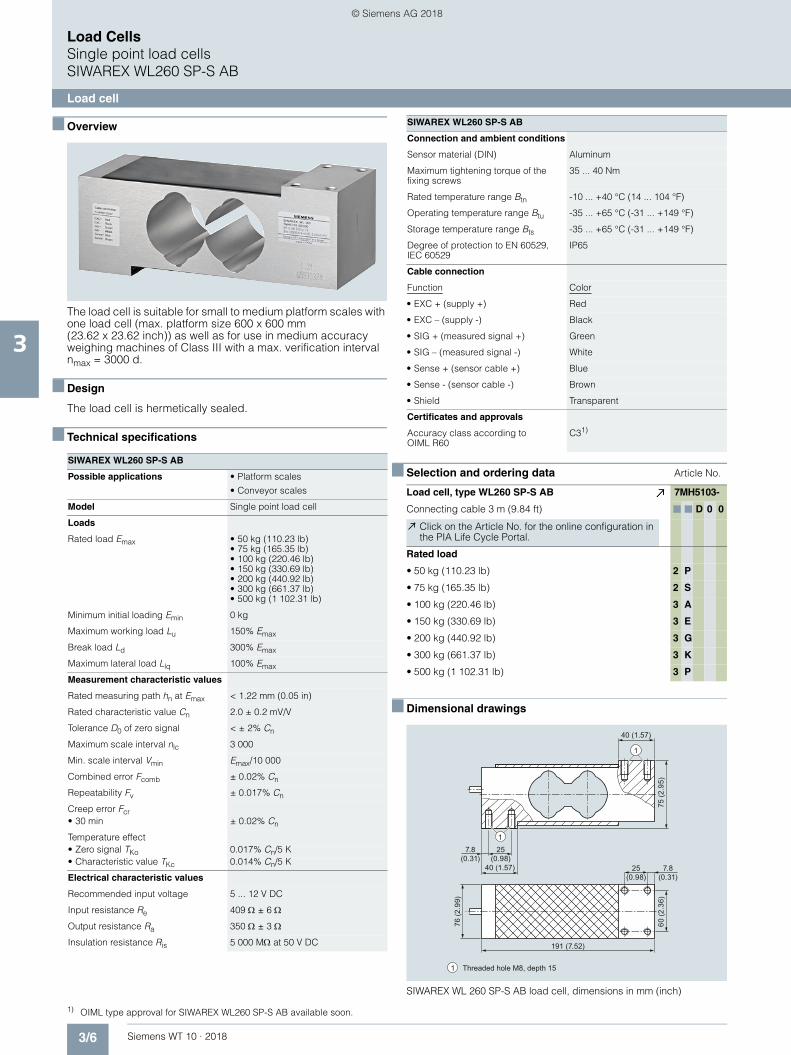
Load CellsSingle point load cellsSIWAREX WL260 SP-S SA
Load cell
3
■ Overview
The load cell is suitable for small to medium platform scales with one load cell (max. platform size 400 x 400 mm) as well as for use in medium accuracy weighing machines of Class III with a max. scale interval number nmax = 3000d.
It is made of stainless steel and therefore also suitable for use in harsh environments.
■ Design
The load cell is hermetically sealed.
■ Technical specifications
■ Selection and ordering data Article No.
SIWAREX WL260 SP-S SA
Possible applications • Platform scales
• Small conveyor scales
Model Single point load cell
Loads
Rated load Emax • 5 kg (11.02 lb)• 10 kg (22.05 lb)• 20 kg (44.09 lb)• 50 kg (110.23 lb)• 100 kg (220.46 lb)• 200 kg (440.92 lb)
Minimum initial loading Emin 0% Emax
Maximum working load Lu 150% Emax
Break load Ld 300% Emax
Maximum lateral load Llq 100% Emax
Measurement characteristic values
Rated measuring path hn at Emax 0.27 ± 0.05 mm (0.01 ± 0.002 in)
Rated characteristic value Cn 2.0 ± 0.2 mV/V
Tolerance D0 of zero signal < ± 1% Cn
Maximum scale interval nlc 3 000
Min. load cell verification interval Vmin Emax/9 000
Combined error Fcomb ± 0.02% Cn
Repeatability Fv ± 0.017% Cn
Creep error Fcr• 30 min ± 0.02% Cn
Temperature coefficient• Zero signal TKo 0.017% Cn/5 K• Characteristic value TKc 0.014% Cn/5 K
Electrical characteristic values
Recommended input voltage 5 ... 12 V DC
Input resistance Re 383 ± 6
Output resistance Ra 351 ± 3
Insulation resistance Ris 5 000 M at 50 V DC
Connection and ambient conditions
Sensor material (DIN) Stainless steel
Maximum tightening torque of the fixing screws• Emax = 3, 5, 10, 20, 50, 100 kg
(6.61, 11.02, 22.05, 44.09, 110.23, 220.46 lb)
14 Nm
• Emax = 200 kg (440.92 lb) 16 Nm
Rated temperature range Btn -10 ... +40 °C (14 ... 104 °F)
Operating temperature range Btu -35 ... +65 °C (-31 ... +149 °F)
Storage temperature range Bts -40 ... +70 °C (-40 ... +158 °F)
Degree of protection to EN 60529, IEC 60529
IP67
Cable connection
Function Color
• EXC + (supply +) Green
• EXC – (supply -) Black
• SIG + (measured signal +) White
• SIG – (measured signal -) Red
• Sense + (sensor cable +) blue
• Sense - (sensor cable -) yellow
• Shield Transparent
Certificates and approvals
Accuracy class according to OIML R60
C3
Load cell, type WL260 SP-S SA 7MH5104-
Legal-for-trade according to OIML R60 to 3000d, 1 m connecting cable (3.28 ft)
■ ■ D 0 ■
Click on the Article No. for the online configuration in the PIA Life Cycle Portal.
Rated load
• 5 kg (11.02 lb) 1 P
• 10 kg (22.05 lb) 2 A
• 20 kg (44.09 lb) 2 G
• 50 kg (110.23 lb) 2 P
• 100 kg (220.46 lb) 3 A
• 200 kg (440.92 lb) 3 G
Explosion protection
Without 0
Explosion protection for zones 0, 1, 2, 20, 21, 22 1
SIWAREX WL260 SP-S SA
WT10-2018_en_Kap03.book Seite 8 Dienstag, 5. Juni 2018 11:50 11
© Siemens AG 2018

3/9Siemens WT 10 · 2018
Load CellsSingle point load cells
SIWAREX WL260 SP-S SA
Load cell
3
■ Dimensional drawings
SIWAREX WL 260 SP-S SA load cell, dimensions in mm (inch)
1
1
Threaded hole M6, thread depth 15, hole depth 181
150 (5.91)
19 (0.75)
40 (1
.57)
31 (1
.22)
38 (1
.50)
38 (1
.50)
25
(0.9
8)
25 (0.98) 25 (0.98)19 (0.75)
34 (1.34)
WT10-2018_en_Kap03.book Seite 9 Dienstag, 5. Juni 2018 11:50 11
© Siemens AG 2018
3/10 Siemens WT 10 · 2018
Load CellsSingle point load cellsSIWAREX WL260 SP-S SB
Load cell
3
■ Overview
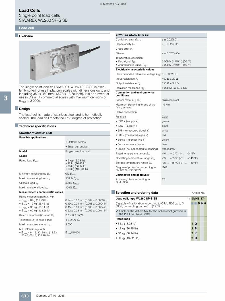
The single point load cell SIWAREX WL260 SP-S SB is excel-lently suited for use in platform scales with dimensions up to and including 350 x 350 mm (13.78 x 13.78 inch). It is approved for use in Class III commercial scales with maximum divisions of nmax to 3 000d.
■ Design
The load cell is made of stainless steel and is hermetically sealed. The load cell meets the IP68 degree of protection.
■ Technical specifications
■ Selection and ordering data Article No.
SIWAREX WL260 SP-S SB
Possible applications
• Platform scales
• Small belt scales
Model Single point load cell
Loads
Rated load Emax • 6 kg (13.23 lb)• 12 kg (26.46 lb)• 30 kg (66.14 lb)• 60 kg (132.28 lb)
Minimum initial loading Emin 0% Emax
Maximum working load Lu 150 % Emax
Ultimate load Ld 300% Emax
Maximum lateral load Llq 100% Emax
Measurement characteristic values
Rated measuring path hn with • Emax = 6 kg (13.23 lb) 0.24 ± 0.02 mm (0.009 ± 0.0008 in)• Emax = 12 kg (26.46 lb) 0.19 ± 0.01 mm (0.008 ± 0.0004 in)• Emax = 30 kg (66.14 lb) 0.15 ± 0.01 mm (0.006 ± 0.0004 in)• Emax = 60 kg (123.28 lb) 0.22 ± 0.03 mm (0.009 ± 0.0011 in)
Rated characteristic value Cn 2.0 ± 0.2 mV/V
Tolerance DO of zero signal < ± 2.0% Cn
Maximum scale interval nlc 3 000
Min. interval Vmin with• Emax = 6, 12, 30, 60 kg (13.23,
26.46, 66.14, 132.28 lb)Emax/15 000
Combined error Fcomb ± 0.02% Cn
Repeatability Fv ± 0.02% Cn
Creep error Fcr
30 min ± 0.025% Cn
Temperature coefficient• Zero signal TKo 0.009% Cn/10 °C (50 °F)• Characteristic value TKc 0.009% Cn/10 °C (50 °F)
Electrical characteristic values
Recommended reference voltage Uref 5 … 12 V DC
Input resistance Re 400 ± 20
Output resistance Ra 350 ± 3.5
Insulation resistance Ris 5 000 M at 50 V DC
Connection and environmental conditions
Sensor material (DIN) Stainless steel
Maximum tightening torque of the fixing screws
10 Nm
Cable connection
Function Color
• EXC + (supply +) green
• EXC – (supply -) black
• SIG + (measured signal +) white
• SIG – (measured signal -) red
• Sense + (sensor line +) yellow
• Sense - (sensor line -) blue
• Shield (not connected to housing) transparent
Rated temperature range Btn -10 ... +40 °C (14 ... 104 °F)
Operating temperature range Btu -35 … +65 °C (-31 ... +149 °F)
Storage temperature range Bts -35 … +65 °C (-31 ... +149 °F)
Degree of protection according to EN 60529; IEC 60529
IP68
Certificates and approvals
Accuracy class according to OIML R60
C3
Load cell, type WL260 SP-S SB 7MH5117-
Capable of calibration according to OIML R60 up to 3 000d, connecting cable 6 m (19.69 ft)
■ ■ D 0 0
Click on the Article No. for the online configuration in the PIA Life Cycle Portal.
Rated load
• 6 kg (13.23 lb) 1 Q
• 12 kg (26.45 lb) 2 B
• 30 kg (66.14 lb) 2 K
• 60 kg (132.28 lb) 2 Q
SIWAREX WL260 SP-S SB
WT10-2018_en_Kap03.book Seite 10 Dienstag, 5. Juni 2018 11:50 11
© Siemens AG 2018

3/11Siemens WT 10 · 2018
Load CellsSingle point load cells
SIWAREX WL260 SP-S SB
Load cell
3
■ Dimensional drawings
SIWAREX WL260 SP-S SB, dimensions in mm (inch)
M6 depth 8 (0.31)(10x)
107.5 (4.23)
13.5 (0.53)
22.5 (0.89)
97.5 (3.84)
116.5 (4.59)
Central load axis
18.5 (0.73) 18.5 (0.73) 18.5 (0.73) 23.5 (0.93)
Rated load[kg (lb)]
50 (1
.97)
24
(0.9
5)
A
20
(0.7
9)
32,5(1.28)
13
(0.5
1) 1
3 (0
.51)
25(0.98)
130 (5.12)
6 (13.23) 12 (26.46) 30 (66.14) 60 (132.28)
A [mm (inch)]
WT10-2018_en_Kap03.book Seite 11 Dienstag, 5. Juni 2018 11:50 11
© Siemens AG 2018
3/12 Siemens WT 10 · 2018
Load CellsSingle point load cellsSIWAREX WL260 SP-S SC
Load cell
3
■ Overview
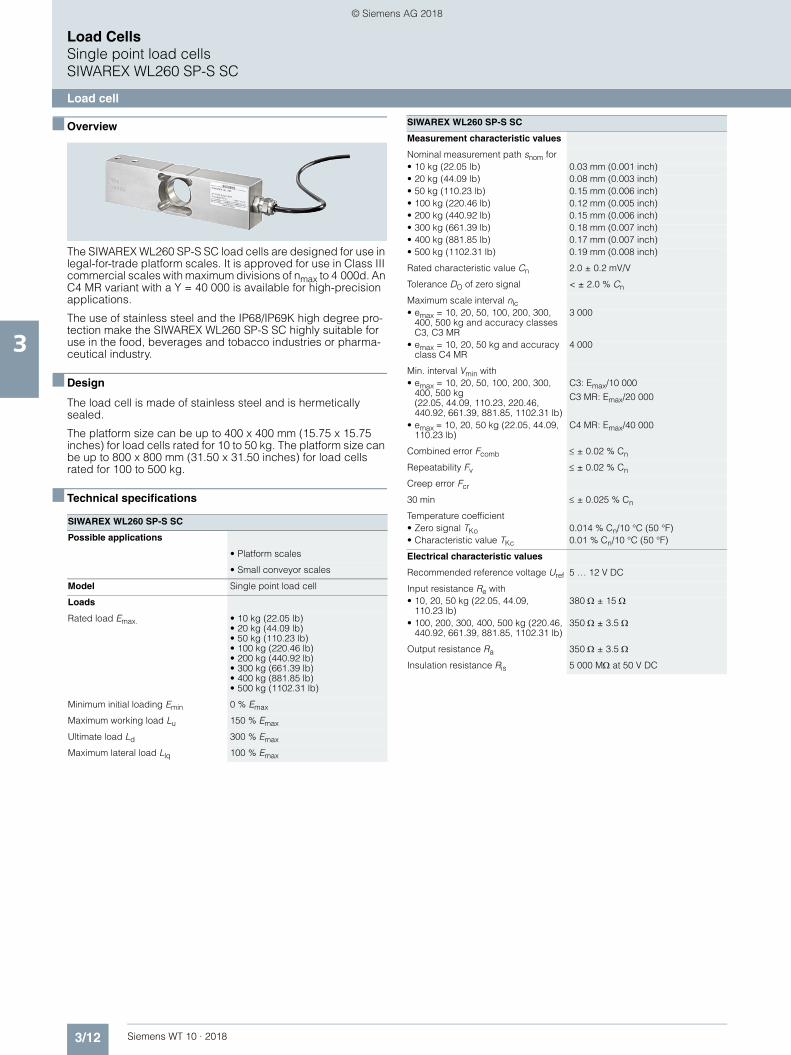
The SIWAREX WL260 SP-S SC load cells are designed for use in legal-for-trade platform scales. It is approved for use in Class III commercial scales with maximum divisions of nmax to 4 000d. An C4 MR variant with a Y = 40 000 is available for high-precision applications.
The use of stainless steel and the IP68/IP69K high degree pro-tection make the SIWAREX WL260 SP-S SC highly suitable for use in the food, beverages and tobacco industries or pharma-ceutical industry.
■ Design
The load cell is made of stainless steel and is hermetically sealed.
The platform size can be up to 400 x 400 mm (15.75 x 15.75 inches) for load cells rated for 10 to 50 kg. The platform size can be up to 800 x 800 mm (31.50 x 31.50 inches) for load cells rated for 100 to 500 kg.
■ Technical specifications
SIWAREX WL260 SP-S SC
Possible applications
• Platform scales
• Small conveyor scales
Model Single point load cell
Loads
Rated load Emax. • 10 kg (22.05 lb)• 20 kg (44.09 lb)• 50 kg (110.23 lb)• 100 kg (220.46 lb)• 200 kg (440.92 lb)• 300 kg (661.39 lb)• 400 kg (881.85 lb)• 500 kg (1102.31 lb)
Minimum initial loading Emin 0 % Emax
Maximum working load Lu 150 % Emax
Ultimate load Ld 300 % Emax
Maximum lateral load Llq 100 % Emax
Measurement characteristic values
Nominal measurement path snom for• 10 kg (22.05 lb) 0.03 mm (0.001 inch)• 20 kg (44.09 lb) 0.08 mm (0.003 inch)• 50 kg (110.23 lb) 0.15 mm (0.006 inch)• 100 kg (220.46 lb) 0.12 mm (0.005 inch)• 200 kg (440.92 lb) 0.15 mm (0.006 inch)• 300 kg (661.39 lb) 0.18 mm (0.007 inch)• 400 kg (881.85 lb) 0.17 mm (0.007 inch)• 500 kg (1102.31 lb) 0.19 mm (0.008 inch)
Rated characteristic value Cn 2.0 ± 0.2 mV/V
Tolerance DO of zero signal < ± 2.0 % Cn
Maximum scale interval nlc• emax = 10, 20, 50, 100, 200, 300,
400, 500 kg and accuracy classes C3, C3 MR
3 000
• emax = 10, 20, 50 kg and accuracy class C4 MR
4 000
Min. interval Vmin with• emax = 10, 20, 50, 100, 200, 300,
400, 500 kg(22.05, 44.09, 110.23, 220.46, 440.92, 661.39, 881.85, 1102.31 lb)
C3: Emax/10 000
C3 MR: Emax/20 000
• emax = 10, 20, 50 kg (22.05, 44.09, 110.23 lb)
C4 MR: Emax/40 000
Combined error Fcomb ± 0.02 % Cn
Repeatability Fv ± 0.02 % Cn
Creep error Fcr
30 min ± 0.025 % Cn
Temperature coefficient• Zero signal TKo 0.014 % Cn/10 °C (50 °F)• Characteristic value TKc 0.01 % Cn/10 °C (50 °F)
Electrical characteristic values
Recommended reference voltage Uref 5 … 12 V DC
Input resistance Re with• 10, 20, 50 kg (22.05, 44.09,
110.23 lb)380 ± 15
• 100, 200, 300, 400, 500 kg (220.46, 440.92, 661.39, 881.85, 1102.31 lb)
350 ± 3.5
Output resistance Ra 350 ± 3.5
Insulation resistance Ris 5 000 M at 50 V DC
SIWAREX WL260 SP-S SC
WT10-2018_en_Kap03.book Seite 12 Dienstag, 5. Juni 2018 11:50 11
© Siemens AG 2018
3/13Siemens WT 10 · 2018
Load CellsSingle point load cells
SIWAREX WL260 SP-S SC
Load cell
3
■ Selection and ordering data 1 Article No.
■ Dimensional drawings
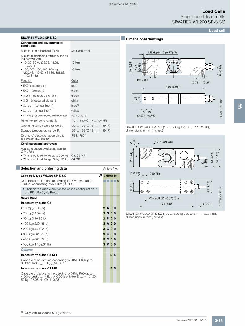
SIWAREX WL260 SP-S SC (10 … 50 kg / 22.05 … 110.23 lb), dimensions in mm (inches)
SIWAREX WL260 SP-S SC (100 … 500 kg / 220.46 … 1102.31 lb), dimensions in mm (inches)
Connection and environmental conditions
Material of the load cell (DIN) Stainless steel
Maximum tightening torque of the fix-ing screws with• 10, 20, 50 kg (22.05, 44.09,
110.23 lb)10 Nm
• 100, 200, 300, 400, 500 kg(220.46, 440.92, 661.39, 881.85, 1102.31 lb)
20 Nm
Function Color
• EXC + (supply +) red
• EXC – (supply -) black
• SIG + (measured signal +) green
• SIG – (measured signal -) white
• Sense + (sensor line +) blue1)
• Sense - (sensor line -) yellow1)
• Shield (not connected to housing) transparent
Rated temperature range Btn -10 ... +40 °C (14 ... 104 °F)
Operating temperature range Btu -35 … +65 °C (-31 ... +149 °F)
Storage temperature range Bts -35 … +65 °C (-31 ... +149 °F)
Degree of protection according to EN 60529; IEC 60529
IP68, IP69K
Certificates and approvals
Available accuracy classes acc. to OIML R60• With rated load 10 kg up to 500 kg C3, C3 MR• With rated load 10 kg, 20 kg, 50 kg C4 MR
1) Only with 10, 20 and 50 kg variants.
Load cell, type WL260 SP-S SC 7MH5118-
Capable of calibration according to OIML R60 up to 3 000d, connecting cable 3 m (9.84 ft)
■ ■ ■ ■ 0
Click on the Article No. for the online configuration in the PIA Life Cycle Portal.
Rated load
In accuracy class C3
• 10 kg (22.05 lb) 2 A D 0
• 20 kg (44.09 lb) 2 G D 0
• 50 kg (110.23 lb) 2 P D 0
• 100 kg (220.46 lb) 3 A D 0
• 200 kg (440.92 lb) 3 G D 0
• 300 kg (661.91 lb) 3 K D 0
• 400 kg (881.85 lb) 3 M D 0
• 500 kg (1 102.31 lb) 3 P D 0
Options
In accuracy class C3 MR D 5
Capable of calibration according to OIML R60 up to 3 000d and Vmin = Emax/20 000
In accuracy class C4 MR E 5
Capable of calibration according to OIML R60 up to 4 000d and Vmin = Emax/40 000; only for Emax = 10, 20, 50 kg (22.05, 44.09, 110.23 lb)
SIWAREX WL260 SP-S SC
19.
1(0
.75)
M6 x 0.5
M6 depth 12 (0.47) (7x)
20 (0
.79)
40 (1
.57)
150 (5.91)
6(0.27)
19 (0.75)
6(0.27)
19 (0.75)
25
(0.9
8)
G_W
T01_
XX
_101
27
62 (2
.44)
G_W
T01_
XX
_101
28
30 (1
.18)
64 (2
.52)
18 (0.71)174 (6.85)45
(1.7
7)62
(2.4
4)
32
(1.2
6)
43 (1.69) (2x)
19 (0.75)7 (0.28)
22
(0.8
7)
M8 depth 22 (0.87) (8x)
WT10-2018_en_Kap03.book Seite 13 Dienstag, 5. Juni 2018 11:50 11
© Siemens AG 2018

3/14 Siemens WT 10 · 2018
Load CellsBending beam load cells
3
■ Overview
Type Bending beam
Possible applications Hopper and belt scales, platform weighing machines
Example picture
Series WL230 BB-S SA
Rated load Emax 10 ... 500 kg (22.05 ... 1 102.31 lb)
Accuracy class C3
Max. load cell verification interval (nIC)
3 000
Min. load cell verification interval (Vmin)
Emax/15 000
Supply voltage (Usr) 5 ... 10 V
Rated characteristic value 2 mV/V
Degree of protection IP68
Material Stainless steel
Ex protection according to ATEX (optional)
II 1G Ex ia IIC T4 Ta= -20 °C ... +40 °CII 3G Ex nL IIC T4 Ta= -20 °C ... +40 °CII 1D Ex iaD 20 IP6x T 73 °C
WT10-2018_en_Kap03.book Seite 14 Dienstag, 5. Juni 2018 11:50 11
© Siemens AG 2018

3/15Siemens WT 10 · 2018
Load CellsBending beam load cells
SIWAREX WL230 BB-S SA
Load cell
3
■ Overview
The bending beam load cell is particularly suitable for use in small-scale container and platform scales.
■ Design
The measuring element is a double bending beam made of stainless steel to which 4 strain gauges are applied.
The strain gauges are arranged so that two are stretched and two are compressed.
Under the influence of the load acting in the measuring direction, the spring bodies and therefore the friction-locked strain gauges are elastically deformed. This generates a measuring signal volt-age that is proportional to the load.
■ Technical specifications1 2
1) Higher accuracy class available on request2) The tightening torque is to be selected according to the strength class of the screws.
SIWAREX WL230 BB-S SA
Possible applications
• Hopper scales
• Conveyor belt scales
• Platform scales
Model Bending beam load cell
Loads
Rated load Emax • 10 kg (22.05 lb)• 20 kg (44.09 lb)• 50 kg (110.23 lb)• 100 kg (220.46 lb)• 200 kg (440.92 lb)• 300 kg (661.39 lb)• 350 kg (771.62 lb)• 500 kg (1102.31 lb)
Minimum initial loading Emin 0% Emax
Maximum working load Lu 150% Emax
Break load Ld 300% Emax
Safe lateral load LIq 100% Emax
Measurement characteristic values
Rated measuring path hn at Emax 0.3 mm (0.01 in)
Rated characteristic value Cn 2.0 ± 0.02% mV/V
Tolerance DO of zero signal < ± 1.0% Cn
Maximum load cell verification interval nLC
3 0001)
Min. load cell verification interval Vmin Emax/15 000
Minimum application range Rmin(LC) 20%
Combined error Fcomb 0.02% Cn
Repeatability Fv 0.017% Cn
Creep error Fcr
30 min ± 0.02% Cn
Temperature coefficient• Zero signal TKo ± 0.017% Cn/5 K• Characteristic value TKc ± 0.014% Cn/5 K
Electrical characteristic values
Recommended reference voltage Uref 5 ... 10 V DC
Input resistance Re 460 ± 50
Output resistance Ra 350 ± 3.5
Insulation resistance Ris 5 000 M at 50 V DC
Current calibration Standard
Connection and environmental conditions
Sensor material (DIN) Stainless steel
Max. tightening torque of the fixing screws• Emax = 10, 20, 50, 100, 200 kg
(22.05, 44.09, 110.23, 220.46, 440.92 lb)
23 Nm2)
• Emax = 350, 500 kg (771.62, 1102.31 lb)
70 Nm2)
Function Color
• EXC + (supply +) Green
• EXC - (supply -) Black
• SIG + (measured signal +) White
• SIG - (measured signal -) Red
• Shield Transparent
Rated temperature range Btn -10 ... +40 °C (14 ... 104 °F)
Operating temperature range Btu -35 ... +65 °C (-31 ... +149 °F)
Storage temperature range Bts -35 ... +65 °C (-31 ... +149 °F)
Degree of protection according to EN 60529; IEC 60529
IP68
Certificates and approvals
Accuracy class according to OIML R60
C3
SIWAREX WL230 BB-S SA
WT10-2018_en_Kap03.book Seite 15 Dienstag, 5. Juni 2018 11:55 11
© Siemens AG 2018

3/16 Siemens WT 10 · 2018
Load CellsBending beam load cellsSIWAREX WL230 BB-S SA
Load cell
3
■ Selection and ordering data Article No. ■ Dimensional drawings
SIWAREX WL230 BB-S SA load cell, dimensions in mm (inch)
Load cells type WL230 BB-S SA 7MH5106-
Legal-for-trade according to OIML R60 to 3 000d, connecting cable 3 m (9.84 ft)
■ ■ D 0 ■
Click on the Article No. for the online configuration in the PIA Life Cycle Portal.
Rated load
• 10 kg (22.05 lb) 2 A
• 20 kg (44.09 lb) 2 G
• 50 kg (110.23 lb) 2 P
• 100 kg (220.46 lb) 3 A
• 200 kg (440.92 lb) 3 G
• 350 kg (771.62 lb) 3 L
• 500 kg (1 102.31 lb) 3 P
Explosion protection
Without 0
Explosion protection for zones 0, 1, 2, 20, 21, 22 1 Rated load [kg]10, 20, 50, 100, 200
350, 500
Ød 8.2 (0.32)
10.3 (0.41)
ØD 23 (0.91)
24 (0.95)
H20 (0.79)
19 (0.75)
HØ
D
ØdØd
10 (0.39)
82 (3.23)18 (0.71)
39 (1
.54)
20
(0.7
9)
120 (4.72)42 (1.65) 21
(0.83)
WT10-2018_en_Kap03.book Seite 16 Dienstag, 5. Juni 2018 11:55 11
© Siemens AG 2018

3/17Siemens WT 10 · 2018
Load CellsBending beam load cells
SIWAREX WL230 BB-S SA
Mounting unit
3
■ Overview
The self-aligning mounting unit for SIWAREX WL230 BB-S SA load cells is particularly suitable for implementation in small-scale container, platform and roller table scales.
■ Design
The mounting unit comprises a base plate and a top plate, a self-aligning bolt, two countersunk screws and overload protection.
The top plate is aligned and fixed above the base plate with the two countersunk screws. This results in a stable unit. The height of the top plate can be adjusted so that it is two millimeters above the installation height with load cell.
In this state the mounting unit serves as an installation aid and can be used as a dummy for light installation jobs.
Prior to installation, the load cell is inserted with the self-aligning bolt into the mounting unit. Then the complete unit is installed in the scales. As the result, the load bearing implement and the in-stallation units are aligned. The load cells are not yet loaded.
Finally the load bearing implement is lowered by undoing two hex nuts under the top plate. The weight now rests on the load cells.
In this state the load cell and the pressure pieces together form a self-centering unit. The mounting unit permits sideways dis-placement of the top plate, and hence of the load bearing imple-ment, by up to 1.5 mm (0.06 in.).
The overload protection is set so that the load cell cannot be loaded beyond the limit load.
■ Technical specifications
■ Selection and ordering data1 2 Article No.
Mounting unit for load cells of the SIWAREX WL230 BB-S SA series
Rated load 10 ... 200 kg (22.01 ... 440.92 lb)
350, 500 kg (771.62, 1102.31 lb)
Permissible lateral deflection:
± 2 mm (0.08 inch) ± 2.5 mm (0.10 inch)
Lifting path of the top plate
2 ... 2.5 mm (0.08 ... 0.10 inch)
3 ... 3.5 mm (0.12 ... 0.14 inch)
Max. lateral force 1.7 kN 2.5 kN
Max. lifting force 2.5 kN 2.5 kN
1) The load cell is not included in the scope of delivery.2) It is highly recommendable to use a grounding cable (7MH3701-1AA1) in order to protect the load cell.
Mounting unitFor load cells of the SIWAREX WL230 BB-S SA series
Material: Stainless steel
for load cells with a rated load of• 10 ... 200 kg (22.05 ... 440.92 lb)1)2)
7MH4133-3DC11• 350, 500 kg (771.61, 1 102.3 lb)1)
7MH4133-3KC11
Shims (accessories)For mounting units of the SIWAREX WL230 BB-S SA series
Material: Stainless steel
For load cells with a rated load of1)
• 10 ... 200 kg (22.05 ... 440.92 lb);Contents: 16 units, each 0.5 mm thick
7MH5713-3JG00
WT10-2018_en_Kap03.book Seite 17 Dienstag, 5. Juni 2018 11:50 11
© Siemens AG 2018
3/18 Siemens WT 10 · 2018
Load CellsBending beam load cellsSIWAREX WL230 BB-S SA
Mounting unit
3
■ Dimensional drawings
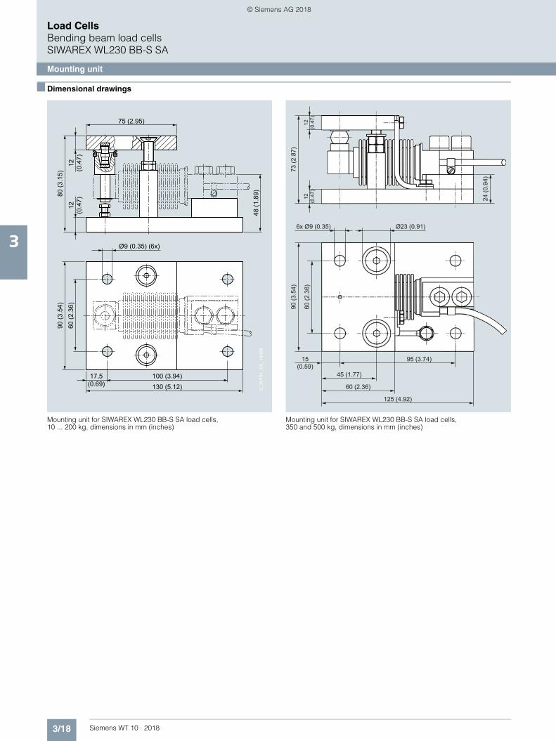
Mounting unit for SIWAREX WL230 BB-S SA load cells, 10 ... 200 kg, dimensions in mm (inches)
Mounting unit for SIWAREX WL230 BB-S SA load cells, 350 and 500 kg, dimensions in mm (inches)
17,5 (0.69)
90 (3
.54)
60 (2
.36)
Ø9 (0.35) (6x)48
(1.8
9)
75 (2.95)
80 (3
.15)
12
(0.4
7)
100 (3.94)130 (5.12)
12
(0.4
7)
G_W
T01_
XX
_100
88
12(0
.47)
12(0
.47)
Ø23 (0.91)6x Ø9 (0.35)
24 (0
.94)
125 (4.92)
60 (2.36)
45 (1.77)
95 (3.74)15(0.59)
90 (3
.54)
60 (2
.36)
73 (2
.87)
WT10-2018_en_Kap03.book Seite 18 Dienstag, 5. Juni 2018 11:50 11
© Siemens AG 2018

3/19Siemens WT 10 · 2018
Load CellsBending beam load cells
SIWAREX WL230 BB-S SA
Elastomer bearing
3
■ Overview
The self-centering elastomer bearing for load cells of the SIWAREX WL230 BB-S SA series is the ideal load introduction element for scales without guide elements. It serves to damp vibrations and shocks.
■ Design
Elastomer bearings are rubber-metal composites made of neo-prene and stainless steel. They ensure large spring excursions (i.e. a high degree of damping) despite small dimensions.
If the load support is displaced by more than 4 mm (0.16 in.) in the horizontal direction, measures for restricting sideways play (e.g. stops) must be provided in the construction of the load bearing implement.
In combination with the base plate and integral overload protec-tion, it is ensured that the load cell is not damaged by static over-loading with vertical forces of up to 5 kN.
The load cell and the base plate are not included in the scope of delivery of the elastomer bearing.
■ Technical specifications
■ Selection and ordering data 1 2 Article No.
■ Dimensional drawings
Elastomer bearings for SIWAREX WL230 BB S SA load cells, 10 ... 200 kg (22.05 … 440.92 lb), dimensions in mm (inch)
Elastomeric bearing for load cells of theSIWAREX WL230 BB-S SA series
Rated load 10 ... 200 kg(22.01 ... 440.92 lb)
350, 500 kg (771.62, 1102.31 lb)
Permissible lateral deflection
± 4 mm (0.16 inch) ± 4 mm (0.16 inch)
1) The load cell is not included in the scope of delivery.2) It is highly recommendable to use a grounding cable (7MH3701-1AA1) in order to protect the load cell.
Elastomer bearingsFor load cells of the SIWAREX WL230 BB-S SA series
Material: Stainless steel
For load cells with a rated load of1)2)
• 10 ... 50 kg (22.05 ... 110.23 lb) 7MH4133-2KE11• 100 ... 200 kg (220.46 ... 440.92 lb) 7MH4133-3DE11• 350, 500 kg (771.61, 1102.31 lb) On request
Ø8.5 (3.35) (4x)
10 (0.39)
100
(3.9
4)
59 (2
.32)
30 (1
.18)
30 (1
.18)
80 (3
.15)
60 (2
.36)
10 (0
.39)
M10Ø50 (1.97)
100 (3.94)
120 (4.72)
10 (0
.39)
WT10-2018_en_Kap03.book Seite 19 Dienstag, 5. Juni 2018 11:50 11
© Siemens AG 2018

3/20 Siemens WT 10 · 2018
Load CellsBending beam load cellsSIWAREX WL230 BB-S SA
Base plate
3
■ Overview
The base plate with integral overload protection for load cells of the SIWAREX WL230 BB-S SA series ensures easy, correct in-stallation of the load cell.
■ Design
The integrated overload protection ensures that the load cell is not damaged by static overloading with vertical forces of up to 5 kN.
The load cells can be installed on the base plate and aligned even before final installation of the scales. This ensures that the permissible spring excursion of the load cell is precisely set, up to contact with the overload protection.
The load cell is not included in the scope of delivery of the base plate with overload protection.
■ Selection and ordering data 1 2 Article No.
■ Dimensional drawings
Elastomer bearing and base plate with overload protection for SIWAREX WL230 BB-S SA load cells, 10 ... 200 kg (22.05 … 440.92 lb), dimensions in mm (inch)
1) The load cell is not included in the scope of delivery2) It is highly recommendable to use a grounding cable (7MH3701-1AA1) in order to protect the load cell.
Base plate with overload protectionFor load cells of the SIWAREX WL230 BB-S SA series
Material: Stainless steel
For load cells with a rated load of1)2)
• 10 ... 200 kg (22.05 ... 440.92 lb) 7MH4133-3DG11• 350 kg (771.62 lb), 500 kg (1102.31 lb) 7MH4133-3KG11
Ø8.5 (0.33) (4x)
10(0.39)
80 (3
.15)
60 (2
.36)
100 (3.94)120 (4.72)
30 (1
.18)
(59)
(2.3
2)
10(0
.39)
WT10-2018_en_Kap03.book Seite 20 Dienstag, 5. Juni 2018 11:50 11
© Siemens AG 2018

3/21Siemens WT 10 · 2018
Load CellsShear beam load cells
3
■ Overview 4
Type Shear beam
Possible applications Hopper, belt, and overhead rail scales and platform weighing machines
Example picture
Series WL230 SB-S SA WL230 SB-S CA
Rated load Emax 500 kg (1 102.31 lb) 1 ... 5 t (0.98 ... 4.92 tn. L.) 100 kg ... 10 t (220.46 lb ... 9.84 tn. L.)
Accuracy class C3 C3, C4, C5
Max. load cell verification interval (nIC)
3 000 3 000 with C3: 3 000with C4: 4 000with C5: 5 000
Min. load cell verification interval (Vmin)
Emax/10 000 Emax/15 000 with C3: 10 000with C4: 15 000with C5: 18 000 (3 t ... 10 t / 2.95 ... 9.84 tn. L.) or 20 000 (0,1 t ... 2 t / 0.1 ... 1.97 tn. L.)
Supply voltage (Usr) 5 ... 12 V 5 ... 12 V
Rated characteristic value 2 mV/V 3 mV/V
Degree of protection IP68 IP68 IP67
Material Stainless steel Special steel, nickel-plated
Ex protection according to ATEX (optional)
II 1G Ex ia IIC T4 Ta= -20 °C ... +40 °CII 3G Ex nL IIC T4 Ta= -20 °C ... +40 °CII 1D Ex iaD 20 IP6x T 73 °C.
–
WT10-2018_en_Kap03.book Seite 21 Dienstag, 5. Juni 2018 11:50 11
© Siemens AG 2018

3/22 Siemens WT 10 · 2018
Load CellsShear beam load cellsSIWAREX WL230 SB-S SA
Load cell
3
■ Overview
The shear beam load cell is particularly suitable for implementa-tion in container, overhead rail conveyor and platform scales.
■ Design
The measuring element is a shear tension spring made of stain-less steel to which strain gauges are applied. The strain gauges are arranged at 45° to the longitudinal axis on the side of the spring body and are therefore subject to shear forces. Under the influence of the load acting in the measuring direction, the spring bodies and therefore the friction-locked strain gauges are elastically deformed. This generates a measuring signal voltage that is proportional to the load.
■ Technical specifications1
1) The tightening torque is to be selected according to the strength class of the screws.
SIWAREX WL230 SB-S SA
Possible applications • Hopper scales
• Conveyor belt scales
• Overhead rail scales
• Platform scales
Model Shear beam load cell
Loads
Rated load/maximum load Emax. • 0.5 t (0.49 tn. L.)• 1 t (0.98 tn. L.)• 2 t (1.97 tn. L.)• 5 t (4.92 tn. L.)
Minimum initial loading Emin 0 kg
Max. working load Lu 150% Emax.
Break load Ld 300% Emax.
Safe lateral load LIq 100% Emax
Measurement characteristic values
Rated measuring path hn at Emax.• Emax = 500 kg (0.49 tn. L.) 0.13 mm (0.005 in)• Emax = 1 t (0.98 tn. L.) 0.21 mm (0.008 in)• Emax = 2 t (1.97 tn. L.) 0.29 mm (0.011 in)• Emax = 5 t (4.92 tn. L.) 0.38 mm (0.014 in)
Rated characteristic value Cn 2.0 ± 0.002 mV/V
Tolerance Do of zero signal ± 1.0% Cn
Max. load cell verification intervals nLC
3 000
Min. load cell verification intervals Vmin• Emax = 500 kg (0.49 tn. L.) Emax/10 000• Emax = 1, 2, 5 t (0.98, 1.97,
4.92 tn. L.)Emax/15 000
Minimum application range Rmin(LC)• Emax = 500 kg (0.49 tn. L.) 30%• Emax = 1, 2, 5 t (0.98, 1.97,
4.92 tn. L.)20%
Combined error Fcomb ± 0.02% Cn
Repeatability Fv ± 0.02% Cn
Creep error Fcr• 30 min ± 0.02% Cn
Temperature coefficient• Zero signal TKo 0.023% Cn/5 K• Characteristic value TKc 0.017% Cn/5 K
Electrical characteristic values
Recommended reference voltage Uref 5 ... 12 V DC
Input resistance Re 1000 ± 10
Output resistance Ra 1004 ± 5
Insulation resistance Ris 5 000 M at 50 V DC
Connection and environmental conditions
Rated temperature range Btn -10 ... +40 °C (14 ... 104 °F)
Operating temperature range Btu -35 ... +65 °C (-31 ... +149 °F)
Storage temperature range Bts -35 ... +65 °C (-31 ... +149 °F)
Sensor material (DIN) Stainless steel
Degree of protection according to EN 60529; IEC 60529
IP68
Recommended tightening torque of the fixing screws• Emax = 0.5, 1, 2 t 150 Nm1)
• Emax = 5 t 550 Nm1)
Cable connection
Function Color
• EXC + Green
• EXC - Black
• SIG + White
• SIG - Red
• Shield Transparent
Certificates and approvals
Accuracy class according to OIML R60
C3
SIWAREX WL230 SB-S SA
WT10-2018_en_Kap03.book Seite 22 Dienstag, 5. Juni 2018 11:50 11
© Siemens AG 2018

3/23Siemens WT 10 · 2018
Load CellsShear beam load cells
SIWAREX WL230 SB-S SA
Load cell
3
■ Selection and ordering data Article No. ■ Dimensional drawings
SIWAREX WL230 SB-S SA load cell, dimensions in mm (inch)
Load cells type WL230 SB-S SA 7MH5107-
Legal-for-trade acc. to OIML R60 up to 3 000d, connecting cable 3 m (9.84 ft) at 500 kg (1 102.31 lb) up to 1 t (0.98 tn. L.),connecting cable 6 m (19.68 ft) at 2 t (1.97 tn. L.) up to 5 t (4.92 tn. L.)
■ ■ D 0 ■
Click on the Article No. for the online configuration in the PIA Life Cycle Portal.
Rated load
• 500 kg (1 102.31 lb) 3 P
• 1 t (0.98 tn. L.) 4 A
• 2 t (1.97 tn. L.) 4 G
• 5 t (4.92 tn. L.) 4 P
Explosion protection
Without 0
Explosion protection for zones 0, 1, 2, 20, 21, 22 1
Rated load[t]
Rated load[t]
2.8
(0.1
1) Ø3.2 (0.13)
25.4(1.00)25.4(1.00)25.4(1.00)38.1(1.50)
13(0.51)13(0.51)13(0.51)20.5(0.81)
0.5
1
2
5
20.5(0.81)20.5(0.81)20.5(0.81)30.2(1.89)
0.5
1
2
5
E
B C D
K
ØG
A
JH
ML
ØF
A
130(5.12)130(5.12)130(5.12)172(6.77)
B
16(0.63)16(0.63)16(0.63)19(0.63)
C D
76(2.99)76(2.99)76(2.99)95(3.74)
ØFE
32(1.26)32(1.26)32(1.26)38(1.50)
ØG H
14(0.55)14(0.55)14(0.55)20(0.79)
J
26(1.02)28(1.10)32(1.26)40(1.57)
K
32(1.26)32(1.26)36(1.42)44(1.73)
M
M12
M12
M12
M20
L
57(2.24)57(2.24)57(2.24)76(2.99)
WT10-2018_en_Kap03.book Seite 23 Dienstag, 5. Juni 2018 11:50 11
© Siemens AG 2018

3/24 Siemens WT 10 · 2018
Load CellsShear beam load cellsSIWAREX WL230 SB-S SA
Mounting unit
3
■ Overview
The self-aligning mounting unit for SIWAREX WL230 SB-S SA load cells is particularly suitable for implementation in container, platform and roller table scales.
■ Design
The mounting unit comprises a base plate and a top plate, a self-aligning bolt and two countersunk screws.
The top plate is aligned and fixed above the base plate with the two countersunk screws. This results in a stable unit. The height of the top plate is adjusted so that it is three millimeters above the installation height with load cell.
In this state the mounting unit serves as an installation aid and can be used as a dummy for light installation jobs.
Prior to installation, the load cell is inserted with the self-aligning bolt into the mounting unit. Then the complete unit is installed in the scales. As the result, the load bearing implement and the in-stallation units are aligned. The load cells are not yet loaded.
Finally the load bearing implement is lowered by undoing two hex nuts under the top plate. The weight now rests on the load cells.
In this state the load cell and the pressure pieces together form a self-centering unit. The mounting unit permits sideways dis-placement of the top plate, and hence of the load bearing imple-ment, by up to three millimeters.
■ Technical specifications
■ Selection and ordering data 1 2 Article No.
Mounting unit for load cells of the SIWAREX WL230 SB-S SA series
Rated load 0.5, 1, 2 t (0.49, 0.98, 1.97 tn. L)
5 t (4.92 tn. L.)
Maximum lateral deflec-tion with load cell
± 3 mm (0.12 inch) ± 3 mm (0.12 inch)
Lifting path of the top plate
3 mm (0.12 inch) 3 mm (0.12 inch)
Restoring force per milli-meter of lateral deflection of the top plate in % of the applied load with load cell
13 %/mm 10%/mm
Permitted supporting load with fixed top plate
25 kN 35 kN
Permitted lifting force on the top plate
25 kN 50 kN
Permitted transverse force on the top plate with fixed top plate
3 kN 5 kN
1) The load cell is not included in the scope of delivery.2) It is highly recommendable to use a grounding cable (7MH3701-1AA1) in order to protect the load cell.
Mounting units 7MH5707-
For load cells of the SIWAREX WL230 SB-S SA series Material: Stainless steelFor load cells with a rated load of:1)2)
4 ■ A 0 0
Click on the Article No. for the online configuration in the PIA Life Cycle Portal.
• 500 kg (1 102.31 lb), 1 t (0.98 tn. L.) A
• 2 t (1.97 tn. L.) G
• 5 t (4.92 tn. L.) P
Shims (accessories)
For mounting units of the SIWAREX WL230 SB-S SA seriesMaterial: Stainless steel
For load cells with a rated load of1)2)
• 500 kg, 1 t, 2 t (0.49, 0.98, 1.97 tn. L)Contents: 16 units, each 0.5 mm thick
7MH5713-3JG00
• 5 t (4.92 tn. L)Contents: 4 units each 0.5 mm thick, 16 units each 1 mm thick
7MH5713-4PG00
WT10-2018_en_Kap03.book Seite 24 Dienstag, 5. Juni 2018 11:50 11
© Siemens AG 2018

3/25Siemens WT 10 · 2018
Load CellsShear beam load cells
SIWAREX WL230 SB-S SA
Mounting unit
3
■ Dimensional drawings
Mounting unit for SIWAREX WL230 SB-S SA load cells, dimensions in mm (inch)
Rated load[t]
Rated load[t]
22.4(0.88)31.6(1.24)
11(4.33)13.5(0.53) G
_WT0
1_X
X_1
0092
B
F
H
MLK
JI
A
DE
CØG (6x)
A
80(3.15)105(4.13)
B C
15(0.59)20(0.79)
D
76(2.99)108(4.25)
F
60(2.36)80(3.15)
E
15(0.59)25(0.98)
ØG H
120(4.72)150(5.91)
I
80(3.14)100(3.94)
J
90(3.54)110(4.33)
s
3(0.12)3 (0.12)
M
140(5.51)185(7.28)
K
110(4.33)145(5.71)
L
15(0.59)20(0.79)
0,5 ... 2
5
0,5 ... 2
5
WT10-2018_en_Kap03.book Seite 25 Dienstag, 5. Juni 2018 11:50 11
© Siemens AG 2018

3/26 Siemens WT 10 · 2018
Load CellsShear beam load cellsSIWAREX WL230 SB-S SA
Base plate with elastomer bearing
3
■ Overview
The base plate and the elastomer bearing form a self-centering bearing unit together with the load cells of the SIWAREX WL230 SB-S SA series. It suppresses oscillations and shocks to a certain extent.
■ Design
Elastomer bearings are rubber-metal composites made of neo-prene and stainless steel. Their special design means that lat-eral movement of the load bearing implement does not result in high transverse force on the load cell.
If the load bearing implement is displaced by more than 4 mm (0.16 inch) in the horizontal direction, measures for restricting sideways play (e.g. stops) must be provided in the construction of the load bearing implement.
The base plate of stainless steel is used for suitable fixing of the load cell on the base.
The load cell is not included in the scope of delivery of the base plate or elastomer bearing.
■ Selection and ordering data Article No.
■ Technical specifications 1 2
Base plate 7MH5707-
For load cells of the SIWAREX WL230 SB-S SA series Material: Stainless steelFor load cells with a rated load of:1)2)
4 ■ ■ 0 0
Click on the Article No. for the online configuration in the PIA Life Cycle Portal.
0,5 … 1 t (0.49 … 0.98 tn L.) A B
2 t (1.97 tn L.) G B
5 t (4.92 tn L.) P B
Elastomer bearings
For load cells of the SIWAREX WL230 SB-S SA series Material: neoprene, stainless steelFor load cells with a rated load of:1)2)
0,5 … 1 t (0.49 … 0.98 tn L.) A C
2 t (1.97 tn L.) G C
5 t (4.92 tn L.) P C
1) The load cell is not included in the scope of delivery.2) It is highly recommendable to use a grounding cable (7MH3701-1AA1) in order to protect the load cell.
Base plate with elastomer bearing for SIWAREX WL230 SB-S SA load cells
Rated load 500 kg (0.49 tn. L.) 1 t (0.98 tn. L.) 2 t (1.97 tn. L.) 5 t (4.92 tn. L.)
Maximum permitted lateral deflection
± 4 mm (0.16 in) ± 4 mm (0.16 in) ± 4 mm (0.16 in) ± 4 mm (0.16 in)
Vertical rigidity 5.9 kN/mm 5.9 kN/mm 29.98 kN/mm 29.98 kN/mm
Horizontal rigidity 0.16 kN/mm 0.16 kN/mm 0.54 kN/mm 0.54 kN/mm
Compression at rated load 0.68 mm (0.037 in) 1.28 mm (0.050 in) 0.62 mm (0.024 in) 1.46 mm (0.057 in)
WT10-2018_en_Kap03.book Seite 26 Dienstag, 5. Juni 2018 11:50 11
© Siemens AG 2018
3/27Siemens WT 10 · 2018
Load CellsShear beam load cells
SIWAREX WL230 SB-S SA
Base plate with elastomer bearing
3
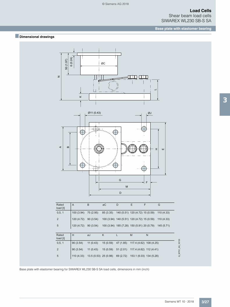
■ Dimensional drawings
Base plate with elastomer bearing for SIWAREX WL230 SB-S SA load cells, dimensions in mm (inch)
Rated load [t]
Rated load [t]
11 (0.43)
11 (0.43)
13.5 (0.53)
117.4 (4.62)
117.4 (4.62)
153.1 (6.03)
K
LH
G
M
D
F
E
6 (0
.24)
50 (1
.97)
ØC
ØJØ11 (0.43)
NA B
75 (2.95)
90 (3.54)
90 (3.54)
100 (3.94)
120 (4.72)
120 (4.72)
0,5, 1
2
5
A øC
85 (3.35)
100 (3.94)
100 (3.94)
D F
140 (5.51)
140 (5.51)
185 (7.28)
E
120 (4.72)
120 (4.72)
150 (5.91)
15 (0.59)
15 (0.59)
20 (0.79)
G
110 (4.33)
110 (4.33)
145 (5.71)
B
90 (3.54)
90 (3.54)
110 (4.33)
0,5, 1
2
5
H øJ
15 (0.59)
15 (0.59)
25 (0.98)
K M
47 (1.85)
51 (2.01)
69 (2.72)
L
108 (4.25)
112 (4.41)
134 (5.28)
N
G_W
T01_
XX
_101
33
WT10-2018_en_Kap03.book Seite 27 Dienstag, 5. Juni 2018 11:50 11
© Siemens AG 2018
3/28 Siemens WT 10 · 2018
Load CellsShear beam load cellsSIWAREX WL230 SB-S CA
Load cell
3
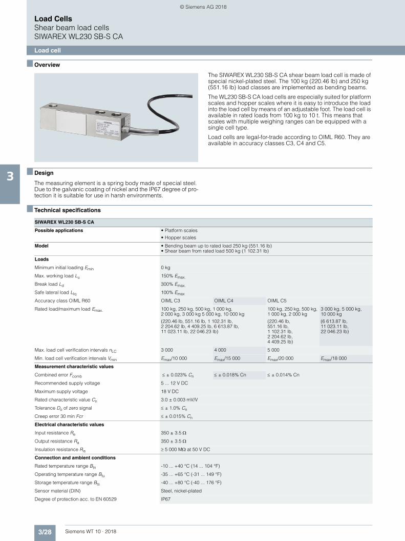
■ Overview
The SIWAREX WL230 SB-S CA shear beam load cell is made of special nickel-plated steel. The 100 kg (220.46 lb) and 250 kg (551.16 lb) load classes are implemented as bending beams.
The WL230 SB-S CA load cells are especially suited for platform scales and hopper scales where it is easy to introduce the load into the load cell by means of an adjustable foot. The load cell is available in rated loads from 100 kg to 10 t. This means that scales with multiple weighing ranges can be equipped with a single cell type.
Load cells are legal-for-trade according to OIML R60. They are available in accuracy classes C3, C4 and C5.
■ Design
The measuring element is a spring body made of special steel. Due to the galvanic coating of nickel and the IP67 degree of pro-tection it is suitable for use in harsh environments.
■ Technical specifications
SIWAREX WL230 SB-S CA
Possible applications • Platform scales
• Hopper scales
Model • Bending beam up to rated load 250 kg (551.16 lb)• Shear beam from rated load 500 kg (1 102.31 lb)
Loads
Minimum initial loading Emin 0 kg
Max. working load Lu 150% Emax.
Break load Ld 300% Emax.
Safe lateral load LIq 100% Emax
Accuracy class OIML R60 OIML C3 OIML C4 OIML C5
Rated load/maximum load Emax. 100 kg, 250 kg, 500 kg, 1 000 kg, 2 000 kg, 3 000 kg 5 000 kg, 10 000 kg
(220.46 lb, 551.16 lb, 1 102.31 lb, 2 204.62 lb, 4 409.25 lb, 6 613.87 lb, 11 023.11 lb, 22 046.23 lb)
100 kg, 250 kg, 500 kg, 1 000 kg, 2 000 kg
(220.46 lb, 551.16 lb, 1 102.31 lb, 2 204.62 lb, 4 409.25 lb)
3 000 kg, 5 000 kg, 10 000 kg
(6 613.87 lb, 11 023.11 lb, 22 046.23 lb)
Max. load cell verification intervals nLC 3 000 4 000 5 000
Min. load cell verification intervals Vmin Emax/10 000 Emax/15 000 Emax/20 000 Emax/18 000
Measurement characteristic values
Combined error Fcomb ± 0.023% Cn ± 0.018% Cn ± 0.014% Cn
Recommended supply voltage 5 ... 12 V DC
Maximum supply voltage 18 V DC
Rated characteristic value Cn 3.0 ± 0.003 mV/V
Tolerance Do of zero signal ± 1.0% Cn
Creep error 30 min Fcr ± 0.015% Cn
Electrical characteristic values
Input resistance Re 350 ± 3.5
Output resistance Ra 350 ± 3.5
Insulation resistance Ris 5 000 M at 50 V DC
Connection and ambient conditions
Rated temperature range Btn -10 ... +40 °C (14 ... 104 °F)
Operating temperature range Btu -35 ... +65 °C (-31 ... 149 °F)
Storage temperature range Bts -40 ... +80 °C (-40 ... 176 °F)
Sensor material (DIN) Steel, nickel-plated
Degree of protection acc. to EN 60529 IP67
WT10-2018_en_Kap03.book Seite 28 Dienstag, 5. Juni 2018 11:50 11
© Siemens AG 2018

3/29Siemens WT 10 · 2018
Load CellsShear beam load cells
SIWAREX WL230 SB-S CA
Load cell
3
■ Selection and ordering data Article No. ■ Dimensional drawings
SIWAREX WL230 SB-S CA load cell
Rated measuring path n at Emax• 100 kg• 250 kg • 500 kg • 1 t • 2 t • 3 t • 5 t • 10 t
• 0.17 mm• 0.15 mm• 0.32 mm • 0.63 mm• 1.2 mm• 0.9 mm• 0.6 mm• 0.8 mm
Recommended tightening torque of the fixing screws• For M12• For M18• For M24
• 75 Nm• 500 Nm• 750 Nm
Length of the connecting cable (four-core)• For rated loads up to 2 t• For rated loads more than 2 t
• Length 4 m• Length 6 m
Diameter of the connecting cable 5 mm
Color coding of the connecting cable Color
• EXC +
• EXC -
• SIG +
• SIG -
• Shield (not connected to the load cell body)
• red
• black
• green
• white
• transparent
ATEX -
SIWAREX WL230 SB-S CA
Load cell, type SIWAREX WL230 SB-S CA 7MH5121-
Material: Stahl, vernickeltLength of the connecting cable: 4 m for rated load up to 2 t, 6 m for rated load more than 3 t
■ ■ ■ 0 0
Click on the Article No. for the online configuration in the PIA Life Cycle Portal.
Rated load
100 kg (220.46 lb) 3 A
250 kg (551.16 lb) 3 H
500 kg (1 102.31 lb) 3 P
1 t (0.98 tn. L.) 4 A
2 t (1.97 tn. L.) 4 G
3 t (2.95 tn. L.) 4 K
5 t (4.92 tn. L.) 4 P
10 t (9.84 tn. L.) 5 A
Accuracy class according to OIML R60
C3 D
C4 E
C5 F
M
B
ØF
L
A
C D
H
K
E G
A–A
A A
A130171.5222.3
0.1t - 2t3t - 5t10t
B15.819.125.4
C25.438.150.8
D76.295.3120.7
E31.838.150.8
ØF13.519.826
G344052.4
H15.818.825.4
K31.838.150.8
L54.277.2101.6
MM12M18x1.5M24x2
WT10-2018_en_Kap03.book Seite 29 Dienstag, 5. Juni 2018 11:50 11
© Siemens AG 2018

3/30 Siemens WT 10 · 2018
Load CellsDouble shear beam load cells
3
■ Overview4
Type Double shear beam
Possible applications Platform scales, hopper scales, vehicle scales
Example picture
Series WL290 DB-S CA
Rated load Emax 13,6 t ..... 34 t (13.39 ... 33.46 tn. L.)
Accuracy class C3
Max. load cell verification interval (nIC)
3 000
Min. load cell verification interval (Vmin)
Emax/10 000
Supply voltage (Usr) 5 ... 12 V
Rated characteristic value 3 mV/V
Degree of protection IP67
Material Steel, nickel-plated
Ex protection according to ATEX (optional)
–
WT10-2018_en_Kap03.book Seite 30 Dienstag, 5. Juni 2018 11:50 11
© Siemens AG 2018

3/31Siemens WT 10 · 2018
Load CellsDouble shear beam load cells
SIWAREX WL290 DB-S CA
Load cell
3
■ Overview
The SIWAREX WL290 DB-S CA double shear beam load cell is made of nickel-plated specialty steel.
WL290 DB-S CA load cells are especially suited for large plat-form and hopper scales. A special mounting unit makes them particularly suitable for assembling scales in vehicles. The dou-ble shear beam load cell is installed without oscillation or elasto-mer force-transmitting mechanisms since transverse forces do not result in the otherwise usual oscillating or deflection effects in the load cell.
Load cells are legal-for-trade according to OIML R60. They are available in accuracy class C3.
■ Design
The measuring element is a spring body made of special steel. Due to the galvanic coating of nickel and the IP67 degree of protection it is suitable for use in harsh environments.
■ Technical specifications
SIWAREX WL290 DB-S CA
Possible applications Platform scales, hopper scales, vehicle scales
Model Double shear beam
Rated load/maximum load Emax. • 13.6 t (13.39 tn. L.)• 18.1 t (17.81 tn. L.)• 22.6 t (22.24 tn. L.)• 27.2 t (26.77 tn. L.)• 34 t (33.46 tn. L.)
Accuracy class according to OIML R60 C3
Max. load cell verification intervals nLC 3 000
Min. scale interval Vmin Emax/10 000
Combined error Fcomb ± 0.023% Cn
Min. dead load Emin 0 kg
Safe load limit Lu 150% Emax
Ultimate load Ld 300% Emax
Recommended supply voltage 5 … 12 V DC
Maximum supply voltage 18 V DC
Rated measuring path hn at Emax• Emax = 13.6 t (13.39 tn. L.), 18.1 t (17.81 tn. L.)
22.6 t (22.24 tn. L.)0.5 mm
• Emax = 27.2 t (26.77 tn. L.) 0.6 mm• Emax = 34 t (33.46 tn. L.) 0.5 mm
Rated characteristic value Cn 3.0 ± 0.008 mV/V
Tolerance Do of zero signal ± 1.0% Cn
Creep error 30 min Fcr ± 0.015% Cn
Input resistance Re 700 ± 7
Output resistance Ra 703 ± 4
Insulation resistance Ris 5 000 M at 50 V DC
Rated temperature range Btn -10 … +40 °C (14 ... 104 °F)
Operating temperature range Btu -35 … +60 °C (-31 ... 140 °F)
Storage temperature range Bts -40 … +80 °C (-40 ... 176 °F)
Sensor material (DIN) Steel, nickel-plated
Degree of protection according to EN 60529; IEC 60529
IP67
Cable connection
Length of the connecting cable (four-core) 9 m (30 ft)
Diameter of the connecting cable 8 mm
Color coding of the connecting cable Color
• EXC + Red
• EXC - Black
• SIG + Green
• SIG - White
• Shield (not connected to the load cell body) Transparent
ATEX -
WT10-2018_en_Kap03.book Seite 31 Dienstag, 5. Juni 2018 11:50 11
© Siemens AG 2018

3/32 Siemens WT 10 · 2018
Load CellsDouble shear beam load cellsSIWAREX WL290 DB-S CA
Load cell
3
■ Selection and ordering data Article No.
■ Dimensional drawings
SIWAREX WL290 DB-S CA load cell (dimensions in mm)
SIWAREX WL290 DB-S CA load cell 7MH5122-
Material: Steel, nickel-platedLength of the connecting cable: 9 m (30 ft)
■ ■ ■ 0 0
Click on the Article No. for the online configuration in the PIA Life Cycle Portal.
Rated load
• 13,6 t (13.39 tn. L.) 5 D
• 18 t (17.81 tn. L.) 5 F
• 23 t (22.24 tn. L.) 5 G
• 27 t (26.77 tn. L.) 5 J
• 34 t (33.46 tn. L.) 5 L
Accuracy class C3 acc. to OIML R60
C3 D
A B C d D E F G H
260.4 215.9 165.1 26.9 76.2 25.4 60.2 25.4 8
ABC
G
Ød
ØD
G_W
T01_
XX
_101
46
ØH
F
EØd
A260.4
Rated Load13.6 t ... 34 t
B215.9
C165.1
Ød26.9
ØD76.2
E25.4
F60.2
GR25.4
ØH8
WT10-2018_en_Kap03.book Seite 32 Dienstag, 5. Juni 2018 11:50 11
© Siemens AG 2018

3/33Siemens WT 10 · 2018
Load CellsDouble shear beam load cells
SIWAREX WL290 DB-S CA
Mounting unit for vehicles
3
■ Overview
SIWAREX WL290 DB-S CA load cell with mounting unit
The mounting unit for the SIWAREX WL290 DB-S CA load cells makes setting up platform and hopper scales easy and safe. Since the load cell is securely bolted onto the bearing plates, it is particularly suitable for use in scales in vehicles. The mounting unit transmits the force directly into the load cell and absorbs any lateral and lifting forces which occur. The mounting unit covers load cell rated loads from 13.6 to 34 t (13.39 to 33.46 tn. L.).
■ Design
The load cell is bolted onto the bearing plates. A two-part bear-ing collar is used to connect the load bearer to the load cell, firmly and without play. The bearing collar transfers the weight force centered into the load cell.
Since all connections are tight, possible acceleration forces, caused for example by a container on a vehicle, are directed to the chassis from the load cell and mounting unit. Additional latching mechanisms are not required. Due to the zero play mounting of the load cell no wear can occur, making any main-tenance measures superfluous.
■ Technical specifications
■ Selection and ordering data1 Article No.
■ Dimensional drawings
Mounting unit for SIWAREX WL290 DB-S CA load cell
Installation unit for load cells of the SIWAREX WL290 DB-S CA series
Rated load 13.6 ... 34 t (13.39 ... 33.46 tn. L.).
Maximum lateral deflection 0 mm
Lifting path of top plate 0 mm
Permissible lateral force 20 kN
Permissible lifting force 35 kN
Tightening torque of mounting bolts for load cells
650 Nm
Tightening torque of mounting bolts for clamp collars
650 Nm
Material Steel, nickel-plated
1) The load cell is not included in the scope of delivery
Mounting unitfor SIWAREX WL290 DB-S CA series load cells
Material: Steel, nickel-plated
for load cells with a rated load of 1)
• 13,6 ... 34 t (13.39 ... 33.46 tn. L.) 7MH5722-5LA11
M24 x 1.5
44
R100
M24 x 1.5 x 150
121.
3
68.1
3016
011
8
50172259305
Ø20
150110
150
110
G_W
T01_
XX
_101
45
WT10-2018_en_Kap03.book Seite 33 Dienstag, 5. Juni 2018 11:50 11
© Siemens AG 2018
3/34 Siemens WT 10 · 2018
Load CellsS-Type load cells
3
■ Overview5
Type S-Type
Possible applications Tension and pressure applications, suspended scales, container weighers, hybrid scales
Example picture
Series WL250 ST-S SA
Rated load Emax 50 ... 100 kg (110.23 ... 220.46 lb) 0,25 ... 2,5 t (0.25 ... 2.46 tn. L.) 5 ... 10 t (4.92 ... 9.84 tn. L.)
Accuracy class C3
Max. load cell verification interval (nIC)
3 000
Min. load cell verification interval (Vmin)
Emax/7 000 Emax/10 000 Emax/12 000
Supply voltage (Usr) 5 ... 12 V
Rated characteristic value 3 mV/V
Degree of protection IP67
Material Stainless steel
Ex protection according to ATEX (optional)
II 1G Ex ia IIC T4 Ta= -20 °C ... +40 °CII 3G Ex nL IIC T4 Ta= -20 °C ... +40 °CII 1D Ex iaD 20 IP6x T 73 °C.
WT10-2018_en_Kap03.book Seite 34 Dienstag, 5. Juni 2018 11:50 11
© Siemens AG 2018
3/35Siemens WT 10 · 2018
Load CellsS-Type load cells
SIWAREX WL250 ST-S SA
Load cell
3
■ Overview
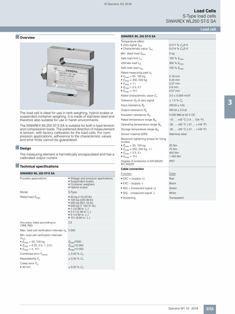
The load cell is ideal for use in tank weighing, hybrid scales or suspended container weighing. It is made of stainless steel and therefore also suitable for use in harsh environments.
The SIWAREX WL250 ST-S SA is suitable for both s-type tension and compression loads. The preferred direction of measurement is tension, with factory calibration for the load cells. For com-pression applications, adherence to the characteristic values and error limits cannot be guaranteed.
■ Design
The measuring element is hermetically encapsulated and has a calibrated output current.
■ Technical specifications
SIWAREX WL 250 ST-S SA
Possible applications • Voltage and pressure applications• Suspended scales• Container weighers • Hybrid scales
Model S-Type
Rated load Emax • 50 kg (110.23 lb)• 100 kg (220.46 lb) • 250 kg (551.16 lb)• 500 kg (1 102.31 lb)• 1 t (0.98 tn. L.)• 2.5 t (2.46 tn. L.)• 5 t (4.92 tn. L.) • 10 t (9.84 tn. L.)
Accuracy class according to OIML R60
C3
Max. load cell verification intervals nlc 3 000
Min. load cell verification intervals Vmin• Emax = 50, 100 kg Emax/7000• Emax = 0.25, 0.5, 1, 2.5 t Emax/10 000• Emax = 5, 10 t Emax/12 000
Combined error Fcomb ± 0.02 % Cn
Repeatability Fv ± 0.02 % Cn
Creep error Fcr• 30 min ± 0.02 % Cn
Temperature effect• Zero signal TK0 0.017 % Cn/5 K• Characteristic value TKc 0.014 % Cn/5 K
Min. dead load Emin 0 kg
Safe load limit Lu 150 % Emax
Ultimate load Ld 300 % Emax
Safe side load LIq 100 % Emax
Rated measuring path hn• Emax = 50, 100 kg 0.18 mm• Emax = 250, 500 kg 0.24 mm• Emax = 1 t 0.37 mm• Emax = 2.5, 5 t 0.8 mm• Emax = 10 t 0.57 mm
Rated characteristic value Cn 3.0 ± 0.008 mV/V
Tolerance D0 of zero signal ± 1.0 % Cn
Input resistance Re 430 ± 4
Output resistance Ra 350 ± 3.5
Insulation resistance Ris 5 000 M at 50 V DC
Rated temperature range Btn -10 … +40 °C (14 ... 104 °F)
Operating temperature range Btu -35 … +65 °C (-31 ... +149 °F)
Storage temperature range Bts -35 … +65 °C (-31 ... +149 °F)
Sensor material (DIN) Stainless steel
Maximum tightening torque for fixing screws• Emax = 50, 100 kg 25 Nm• Emax = 250, 500 kg, 1 t 75 Nm• Emax = 2.5, 5 t 450 Nm• Emax = 10 t 1 450 Nm
Degree of protection to EN 60529; IEC 60529
IP67
Cable connection
Function Color
• EXC + (supply +) Red
• EXC – (supply -) Black
• SIG + (measured signal +) Green
• SIG – (measured signal -) White
• Screening Transparent
SIWAREX WL 250 ST-S SA
WT10-2018_en_Kap03.book Seite 35 Dienstag, 5. Juni 2018 11:50 11
© Siemens AG 2018
3/36 Siemens WT 10 · 2018
Load CellsS-Type load cellsSIWAREX WL250 ST-S SA
Load cell
3
■ Selection and ordering data Article No. ■ Dimensional drawings
SIWAREX WL 250 ST-S SA load cell, dimensions in mm (inch)
Load cells type WL250 ST-S SA 7MH5105-
Legal-for-trade according to OIML R60 up to 3 000d, connecting cable 6 m (19.69 ft)
■ ■ D 0 ■
Click on the Article No. for the online configuration in the PIA Life Cycle Portal.
Rated load
• 50 kg (110.23 lb) 2 P
• 100 kg (220.46 lb) 3 A
• 250 kg (551.16 lb) 3 H
• 500 kg (tn. L..31 lb) 3 P
• 1 t (0.98 tn. L.) 4 A
• 2,5 t (2.46 tn. L.) 4 H
• 5 t (4.92 tn. L.) 4 P
• 10 t (9.84 tn. L.) 5 A
Explosion protection
Without 0
Explosion protection for zones 0, 1, 2, 20, 21, 22 1
Rated load[kg]
Rated load[t]
50.8(2.00)50.8(2.00)
1
2.5
5.0
10
M12
M20 x 1.5
M20 x 1.5
M30 x 2
60.96(2.40)60.96(2.40)
11.68(0.46)18.03(0.71)
15.06(0.59)21.41(0.84)
50.8(2.00)76.2(3.00)74.68(2.94)112.78(4.44)
60.96(2.40)99.06(3.90)99.06(3.90)177.8(7.00)
24.38(0.96)24.38(0.96)30.74(1.21)42.93(1.69)
27.76(1.09)27.76(1.09)34.12(1.34)46.31(1.82)
B
bM
H
L
M
50 … 100
250 … 500
L H b B M
M8
M12
L H b B M
WT10-2018_en_Kap03.book Seite 36 Dienstag, 5. Juni 2018 11:50 11
© Siemens AG 2018
3/37Siemens WT 10 · 2018
Load CellsCompression load cells
3
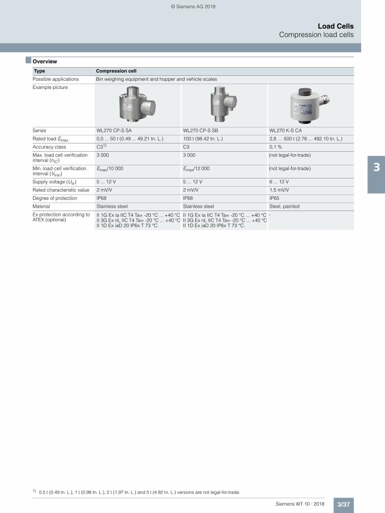
■ Overview6
1
Type Compression cell
Possible applications Bin weighing equipment and hopper and vehicle scales
Example picture
Series WL270 CP-S SA WL270 CP-S SB WL270 K-S CA
Rated load Emax 0,5 ... 50 t (0.49 ... 49.21 tn. L.) 100 t (98.42 tn. L.) 2,8 … 500 t (2.76 ... 492.10 tn. L.)
Accuracy class C31) C3 0,1 %
Max. load cell verification interval (nIC)
3 000 3 000 (not legal-for-trade)
Min. load cell verification interval (Vmin)
Emax/10 000 Emax/12 000 (not legal-for-trade)
Supply voltage (Usr) 5 ... 12 V 5 ... 12 V 6 ... 12 V
Rated characteristic value 2 mV/V 2 mV/V 1,5 mV/V
Degree of protection IP68 IP68 IP65
Material Stainless steel Stainless steel Steel, painted
Ex protection according to ATEX (optional)
II 1G Ex ia IIC T4 Ta= -20 °C ... +40 °CII 3G Ex nL IIC T4 Ta= -20 °C ... +40 °CII 1D Ex iaD 20 IP6x T 73 °C.
II 1G Ex ia IIC T4 Ta= -20 °C ... +40 °CII 3G Ex nL IIC T4 Ta= -20 °C ... +40 °CII 1D Ex iaD 20 IP6x T 73 °C.
-
1) 0.5 t (0.49 tn. L.), 1 t (0.98 tn. L.), 2 t (1.97 tn. L.) and 5 t (4.92 tn. L.) versions are not legal-for-trade.
WT10-2018_en_Kap03.book Seite 37 Dienstag, 5. Juni 2018 11:50 11
© Siemens AG 2018

3/38 Siemens WT 10 · 2018
Load CellsCompression load cellsSIWAREX WL270 CP-S SA
Load cell
3
■ Overview
The compression load cell is particularly suitable for implemen-tation in container, hopper and vehicle scales.
■ Design
The measuring element is a solid cylinder made of stainless steel to which 4 strain gauges are applied.
The load which acts centrally in the measuring direction causes the spring bodies and therefore the friction-locked strain gauges to be elastically deformed. This generates a measuring signal voltage that is proportional to the load.
■ Technical specifications
■ Selection and ordering data 1 Article No.
SIWAREX WL270 CP-S SA
Possible applications Vehicle scales, overhead rail scales, hopper scales
Model Compression load cell
Rated load/maximum load Emax. • 0.5 t (0.49 tn. L.)• 1 t (0.98 tn. L.)• 2 t (1.97 tn. L.)• 5 t (4.42 tn. L.)• 10 t (9.84 tn. L.)• 20 t (19.68 tn. L.)• 30 t (29.53 tn. L.)• 50 t (49.21 tn. L.)
Accuracy class according to OIML R60
C31)
Max. load cell verification intervals nlc 3 000
Min. load cell verification intervals Vmin
Emax/10 000
Minimum application range Rmin(lc) 30%
Combined error Fcomb ± 0.02% Cn
Repeatability Fv Not applicable
Creep error Fcr• 30 min ± 0.023% Cn
Temperature effect• Zero signal TKo 0.023% Cn/5 K• Characteristic value TKc 0.017% Cn/5 K
Min. dead load Emin 0 kg
Safe load limit Lu 150% Emax
Ultimate load Ld 150% Emax
Safe side load LIq 75% Emax
Rated measuring path hn at Emax 0.5 mm
Recommended supply voltage (range)
5 … 12 V DC
Rated characteristic value Cn 2.0 ± 0.02 mV/V
Tolerance DO of zero signal ± 1.0% Cn
Input resistance Re 700 ± 7
Output resistance Ra 700 ± 7
Insulation resistance Ris 5 000 M at 50 V DC
Rated temperature range Btn -10 … +40 °C (-14 ... 104 °F)
Operating temperature range Btu -35 … +65 °C (-31 ... 149 °F)
Storage temperature range Bts -35 … +65 °C (-31 ... 149 °F)
Sensor material Stainless steel
Degree of protection according to EN 60529; IEC 60529
IP68
Cable connection
Function Color
• EXC + (supply +) red
• EXC – (supply -) black
• SIG + (measured signal +) green
• SIG – (measured signal -) white
• Screening transparent
1) SIWAREX WL270 CP-S SA 0.5 t, 1 t, 2 t and 5 t are not approved for legal-for-trade operation.
Load cells type WL270 CP-S SA 7MH5108-
Legal-for-trade according to OIML R60 to 3000d, 15 m connecting cable (49.21 ft)
■ ■ D 0 ■
Click on the Article No. for the online configuration in the PIA Life Cycle Portal.
Rated load
0,5 t (0.49 tn. L.) 1) 3 P
1 t (0.98 tn. L.) 1) 4 A
2 t (1.97 tn. L.) 1) 4 G
5 t (4.92 tn. L.) 1) 4 P
10 t (9.84 tn. L.) 5 A
20 t (19.68 tn. L.) 5 G
30 t (29.63 tn. L.) 5 K
50 t (49.21 tn. L.) 5 P
Explosion protection
Without 0
Explosion protection for zones 0, 1, 2, 20, 21, 22 1
SIWAREX WL270 CP-S SA
WT10-2018_en_Kap03.book Seite 38 Dienstag, 5. Juni 2018 11:50 11
© Siemens AG 2018
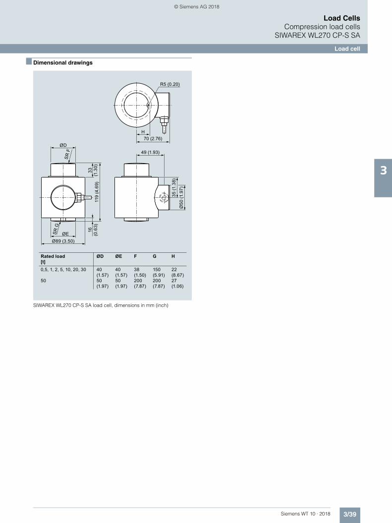
3/39Siemens WT 10 · 2018
Load CellsCompression load cells
SIWAREX WL270 CP-S SA
Load cell
3
■ Dimensional drawings
SIWAREX WL270 CP-S SA load cell, dimensions in mm (inch)
Rated load[t]
H
ØD
Ø89 (3.50)ØE 16
(0
.63)
119
(4.6
9)33
(1
.30)
Ø50
(1.9
7)35
(1.3
8)
49 (1.93)
R5 (0.20)
70 (2.76)
SR
F
SR
G
ØD
40(1.57)50(1.97)
ØE
40(1.57)50(1.97)
F
38(1.50)200(7.87)
G
150(5.91)200(7.87)
H
22(8.67)27(1.06)
0,5, 1, 2, 5, 10, 20, 30
50
WT10-2018_en_Kap03.book Seite 39 Dienstag, 5. Juni 2018 11:50 11
© Siemens AG 2018

3/40 Siemens WT 10 · 2018
Load CellsCompression load cellsSIWAREX WL270 CP-S SA
Mounting unit and guide element
3
■ Overview
The self-aligning mounting unit for SIWAREX WL270 CP-S SA load cells is particularly suitable for implementation in container, platform, vehicle and roller table scales. The guide elements prevent containers, for example, from moving sideways due to an external lateral force. The guide elements can be mounted on one or both sides of the mounting unit.
■ Design
The mounting unit comprises a base plate and a top plate, two pressure pieces and two countersunk screws. A highly flexible grounding cable between the top and base plate conducts any fault currents past the load cell. On both sides of the base and top plate, there are threaded holes for the later flange-fitting of guide elements.
The top plate is aligned and fixed above the base plate with the two countersunk screws. This results in a stable unit. The height of the top plate is adjusted so that it is three millimeters above the installation height with load cell.
In this state the mounting unit serves as an installation aid and can be used as a dummy for light installation jobs.
The load cell can be inserted into the mounting unit together with the two thrust pads. Load cell and thrust pad are secured with clamping washers.
The load cell can be inserted in the scale before installing the mounting unit. In the same way, it is possible to insert the load cell after installation in the mounting unit.
After the mounting unit has been mounted in the scale, the load bearing element is ideally aligned. The load cells are not yet loaded.
Finally the load bearing implement is lowered by undoing two hex nuts under the top plate. The weight now rests on the load cells.
In this state the load cell and the pressure pieces together form a self-centering unit. The mounting unit permits sideways dis-placement of the top plate, and hence of the load bearing imple-ment, by up to three millimeters in all directions. The countersunk screws prevent the load bearing implement from being lifted off or toppling off.
Using the mounting unit as an installation aid results in optimum alignment of the load cells. This is essential for the load cells to perform at their best in terms of accuracy.
For maintenance or troubleshooting purposes the load cell can be relieved again by screwing up the hex nuts. After loosening the clamping washers, it can then easily be replaced.
Guide elements are used if the lateral movement of a load bear-ing element is to be prevented. Lateral movements can be initi-ated by agitator start-up in a container, by braking or accelerat-ing forces in a roller conveyor, or though forces exerted by the wind on outdoor silos.
A guide element consists of two flanges and one clamping screw. The clamping screw is adjusted to the correct length. The guide element is attached to the operational mounting unit. A guide element can be mounted on the front or rear of the mounting unit. If necessary, two guide elements can be used in parallel in order to double the transferrable lateral force.
In the case of scales with four load cells, only three mounting units may be equipped with guide elements.
Shims are used to compensate for angular errors and delays in the lugs. If more than three load cells are used, the shims are also used to adjust the height of the lugs.
WT10-2018_en_Kap03.book Seite 40 Dienstag, 5. Juni 2018 11:50 11
© Siemens AG 2018

3/41Siemens WT 10 · 2018
Load CellsCompression load cells
SIWAREX WL270 CP-S SA
Mounting unit and guide element
3
■ Technical specifications1
■ Selection and ordering data 2 Article No.
1) The values apply to one guide element.
Mounting unit for load cells of the SIWAREX WL270 CP-S SA series
Rated load 0.5, 1, 2, 5, 10, 20, 30 t (0.49, 0.98, 1.97, 5.92, 9.84, 19.68, 29.53 tn. L.)
50 t (49.21 tn. L.)
Maximum lateral deflection with load cell ± 3 mm (0.12 inch) ± 3 mm (0.12 inch)
Lifting path of the top plate 3 mm (0.12 inch) 3 mm (0.12 inch)
Restoring force per millimeter of lateral deflection of the top plate in % of the applied load with load cell
0.5%/mm 2%/mm
Permitted supporting load with fixed top plate 70 kN 70 kN
Permitted lifting force on the top plate 70 kN 70 kN
Permitted transverse force on the top plate with fixed top plate
30 kN 30 kN
Stainless steel guide elements
Size Values with rated load
0.5 t ... 1 t 2 t ... 5 t 10 t ... 20 t 30 t 50 t
Permitted transverse force1)
2.5 kN 5 kN 10 kN 15 kN 25 kN
2) The load cell and the guide elements are not included in the scope of delivery
Mounting units 7MH5708-
For load cells of the SIWAREX WL270 CP-S SA series Material: Stainless steelFor load cells with a rated load of2)
5 ■ A 0 1
Click on the Article No. for the online configuration in the PIA Life Cycle Portal.
• 0,5, 1, 2, 5, 10, 20, 30 t (0.49, 0.98, 1.97, 5.92, 9.84, 19.68, 29.53 tn. L.)
K
• 50 t (49.21 tn. L.) P
Guide element (optional) 7MH5708-
For mounting units of the SIWAREX WL270 CP-S SA seriesMaterial: EdelstahlFor load cells with a rated load of
■ ■ E 0 0
• 0,5… 1 t (0.49 ... 0.98 tn. L.);Permitted transverse force: 2,5 kN
4 A
• 2 … 5 t (1.97 ... 5.92 tn. L.);Permitted transverse force: 5 kN
4 P
• 10 … 13 t (9.84 ... 12.79 tn. L.);Permitted transverse force: 10 kN
5 G
• 30 t (29.53 tn. L.);Permitted transverse force: 15 kN
5 K
• 50 t (49.21 tn. L.);Permitted transverse force: 25 kN
5 P
Shims (accessories) 7MH5708-
For mounting units of the SIWAREX WL270 CP-S SA seriesMaterial: Stainless steelFor load cells with a rated load of2)
5 ■ G 0 0
• 0,5 ... 50 t (1.97 ... 29.53 tn. L.);Contents: 4 units, each 0.5 mm; 20 units, each 1 mm
P
WT10-2018_en_Kap03.book Seite 41 Dienstag, 5. Juni 2018 11:50 11
© Siemens AG 2018

3/42 Siemens WT 10 · 2018
Load CellsCompression load cellsSIWAREX WL270 CP-S SA
Mounting unit and guide element
3
■ Dimensional drawings
Mounting unit for SIWAREX WL270 CP-S SA load cells, dimensions in mm (inches)
Guide element for SIWAREX WL270 CP-S SA load cells, dimensions in mm (inches)
20 (0
.79)
Ø22
240 ( 9.45)
145
(5.7
)
160 (6.3)
100
(3.9
4)20
2 ±
1 (7
.95
±0.0
4)20
(0.7
9)
BD
C
A
0.5 t ~ 1 t(0.49 ~ 0.98 tn.L)
240 (9.45)205 (8.07)12 (0.47)
≈35.6 (≈1.4)
2 t ~ 5 t(1.97 ~ 4.92 tn.L)
240 (9.45)205 (8.07)18 (0.71)
≈45.5 (≈1.79)
10 t ~ 20 t(9.84 ~ 19.68 tn.L)
240 (9.45)205 (8.07)18 (0.71)
≈54.4 (≈2.14)
30 t(29.53 tn.L)
240 (9.45)205 (8.07)27 (1.06)
≈70.5 (≈2.78)
50 t(49.21 tn.L)
270 (10.63)205 (8.07)30 (1.18)
≈84 (≈3.31)
ABCD
WT10-2018_en_Kap03.book Seite 42 Dienstag, 5. Juni 2018 11:50 11
© Siemens AG 2018
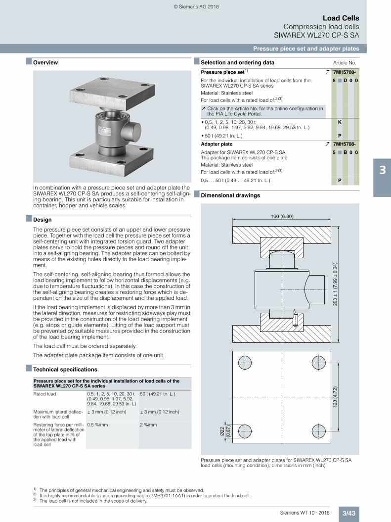
3/43Siemens WT 10 · 2018
Load CellsCompression load cells
SIWAREX WL270 CP-S SA
Pressure piece set and adapter plates
3
■ Overview
In combination with a pressure piece set and adapter plate the SIWAREX WL270 CP-S SA produces a self-centering self-align-ing bearing. This unit is particularly suitable for installation in container, hopper and vehicle scales.
■ Design
The pressure piece set consists of an upper and lower pressure piece. Together with the load cell the pressure piece set forms a self-centering unit with integrated torsion guard. Two adapter plates serve to hold the pressure pieces and round off the unit into a self-aligning bearing. The adapter plates can be bolted by means of the existing holes directly to the load bearing imple-ment.
The self-centering, self-aligning bearing thus formed allows the load bearing implement to follow horizontal displacements (e.g. due to temperature fluctuations). In this case the construction of the self-aligning bearing creates a restoring force which is de-pendent on the size of the displacement and the applied load.
If the load bearing implement is displaced by more than 3 mm in the lateral direction, measures for restricting sideways play must be provided in the construction of the load bearing implement (e.g. stops or guide elements). Lifting of the load support must be prevented by suitable measures provided in the construction of the load bearing implement.
The load cell must be ordered separately.
The adapter plate package item consists of one unit.
■ Technical specifications
■ Selection and ordering data 1 2 3 Article No.
■ Dimensional drawings
Pressure piece set and adapter plates for SIWAREX WL270 CP-S SA load cells (mounting condition), dimensions in mm (inch)
Pressure piece set for the individual installation of load cells of the SIWAREX WL270 CP-S SA series
Rated load 0.5, 1, 2, 5, 10, 20, 30 t (0.49, 0.98, 1.97, 5.92, 9.84, 19.68, 29.53 tn. L)
50 t (49.21 tn. L.)
Maximum lateral deflec-tion with load cell
± 3 mm (0.12 inch) ± 3 mm (0.12 inch)
Restoring force per milli-meter of lateral deflection of the top plate in % of the applied load with load cell
0.5 %/mm 2 %/mm
1) The principles of general mechanical engineering and safety must be observed.2) It is highly recommendable to use a grounding cable (7MH3701-1AA1) in order to protect the load cell.3) The load cell is not included in the scope of delivery.
Pressure piece set1) 7MH5708-
For the individual installation of load cells from the SIWAREX WL270 CP-S SA seriesMaterial: Stainless steelFor load cells with a rated load of:2)3)
5 ■ D 0 0
Click on the Article No. for the online configuration in the PIA Life Cycle Portal.
• 0,5, 1, 2, 5, 10, 20, 30 t (0.49, 0.98, 1.97, 5.92, 9.84, 19.68, 29.53 tn. L.)
K
• 50 t (49.21 tn. L.) P
Adapter plate 7MH5708-
Adapter for SIWAREX WL270 CP-S SAThe package item consists of one plate.Material: Stainless steelFor load cells with a rated load of:2)3)
5 ■ B 0 0
0,5 … 50 t (0.49 … 49.21 tn. L.) P
Ø22
(0.8
7)
120
(4.7
2)20
3 ±
1 (7
.99
± 0.
04)
160 (6.30)
WT10-2018_en_Kap03.book Seite 43 Dienstag, 5. Juni 2018 11:50 11
© Siemens AG 2018

3/44 Siemens WT 10 · 2018
Load CellsCompression load cellsSIWAREX WL270 CP-S SB
Load cell
3
■ Overview
The compression load cell is particularly suitable for implemen-tation in container, hopper and vehicle scales.
■ Design
The measuring element is a solid cylinder made of stainless steel to which 4 strain gauges are applied.
The load which acts centrally in the measuring direction causes the spring bodies and therefore the friction-locked strain gauges to be elastically deformed. This generates a measuring signal voltage that is proportional to the load.
■ Technical specifications
■ Selection and ordering data Article No.
SIWAREX WL270 CP-S SB
Possible applications Container weighers
Model Compression load cell
Rated load/maximum load Emax. 100 t
Accuracy class according to OIML R60
C3
Max. load cell verification intervals nLC
3 000
Min. scale intervals Vmin• Emax = 100 t Emax/9 000
Minimum application range Rmin(LC) 33%
Combined error Fcomb ± 0.02% Cn
Repeatability Fv ± 0.02% Cn
Creep error Fcr• 30 min ± 0.023% Cn
Temperature effect• Zero signal TKo 0.023% Cn/5 K• Characteristic value TKc 0.017% Cn/5 K
Min. dead load Emin 0 kg
Safe load limit Lu 150% Emax
Ultimate load LD 300% Emax
Safe side load LIq 10% Emax
Rated measuring path hn at Emax 0.36 mm
Recommended supply voltage (range)
5 … 12 V DC
Rated characteristic value Cn 2.0 ± 0.02 mV/V
Tolerance D0 of zero signal ± 1.0% Cn
Input resistance Re 700 ± 7
Output resistance Ra 700 ± 7
Insulation resistance Ris 5 000 M at 50 V DC
Rated temperature range Btn -10 … +40 °C (14 ... 104 °F)
Operating temperature range Btu -35 … +65 °C (-31 ... 149 °F)
Storage temperature range Bts -35 … +65 °C (-31 ... 149 °F)
Sensor material Stainless steel
Degree of protection according to EN 60529; IEC 60529
IP68
Cable connection
Function Color
• EXC + (supply +) green
• EXC – (supply -) black
• SIG + (measured signal +) white
• SIG – (measured signal -) red
• Sense + (sensor line +) yellow
• Sense – (sensor line -) blue
• Screening transparent
Load cells type WL270 CP-S SB 7MH5110-
Legal-for-trade according to OIML R60 to 3000d, 20 m connecting cable
■ ■ D 0 ■
Click on the Article No. for the online configuration in the PIA Life Cycle Portal.
Rated load
100 t (98.42 tn. L.) 6 A
Explosion protection
• Without 0
• Explosion protection for zones 0, 1, 2, 20, 21, 22 1
SIWAREX WL270 CP-S SB
WT10-2018_en_Kap03.book Seite 44 Dienstag, 5. Juni 2018 11:50 11
© Siemens AG 2018
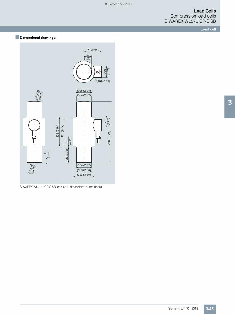
3/45Siemens WT 10 · 2018
Load CellsCompression load cells
SIWAREX WL270 CP-S SB
Load cell
3
■ Dimensional drawings
SIWAREX WL 270 CP-S SB load cell, dimensions in mm (inch)
260
(10.
24)
31
(1.2
2)
SR
400
(15.
75)
76 (2.99)
32 (1.26)
R6 (0.24)
Ø50
(1
.97)
Ø68 (2.68)Ø64 (2.52)
Ø93 (3.66)
Ø68 (2.68)
Ø64 (2.52)
SR
400
(15.
75)
12
(0.4
7)
4 (0
.16)
66 (2
.60)
120
(4.7
2)
128
(5.0
4)
WT10-2018_en_Kap03.book Seite 45 Dienstag, 5. Juni 2018 11:50 11
© Siemens AG 2018

3/46 Siemens WT 10 · 2018
Load CellsCompression load cellsSIWAREX WL270 CP-S SB
Mounting unit
3
■ Overview
The self-centering compact mounting unit for SIWAREX WL270 CP-S SA load cells is particularly suitable for implementation in container scales.
■ Design
The compact mounting unit comprises a base plate and a top plate, two pressure pieces, two clamping pieces and two center-ing sleeves. There are threaded holes in the base plate and top plate for the subsequent flange-fitting of guide elements.
The top plate is aligned and fixed above the base plate with the two centering sleeves. This results in a stable unit. The height of the top plate is adjusted so that it is five millimeters above the in-stallation height with load cell.
Two pressure pieces are used to mount the load cell. They are fastened flush with the head plate and base plate using the clamping pieces.
In this state the compact mounting unit serves as an installation aid and can be used as a dummy for light installation jobs.
Prior to installation, the load cell is inserted into the compact mounting unit. Then the complete unit is installed in the scales. As the result, the load bearing implement and the mounting units are aligned. The load cells are not yet loaded.
Finally the load bearing implement is lowered by undoing two hex nuts under the centering sleeves. The weight now rests on the load cells.
In this state the load cell and the pressure pieces together form a self-centering unit. The compact mounting unit permits side-ways displacement of the top plate, and hence of the load bear-ing implement, by up to eight millimeters in all directions. Two countersunk screws prevent the load bearing implement from being lifted off or toppling off.
Using the compact mounting unit as an installation aid results in optimum alignment of the load cells. This is essential for the load cells to perform at their best in terms of accuracy.
For maintenance or troubleshooting purposes the load cell can be relieved again by screwing up the hex nuts. Replacement of the load cell is then easy after the clamping pieces are released.
■ Technical specifications
■ Selection and ordering data Article No.
■ Dimensional drawings1 2
Compact mounting unit for SIWAREX WL270 CP-S SB load cells (mounting condition), dimensions in mm (inch)
Mounting unit for load cells of theSIWAREX WL270 CP-S SB series
Rated load 100 t (98.42 tn. L)
Maximum lateral deflection withload cell
± 8 mm (0.12 inch)
Lifting path of the top plate 3 ... 5 mm (0.12 ... 0.20 inch)
Restoring force per millimeter of lat-eral deflection of the top plate in % of the applied load with load cell
0.5 %/mm
Permitted supporting load with fixed top plate
140 kN
Permitted lifting force on the top plate 140 kN
Permitted transverse force on the top plate with fixed top plate
50 kN
Compact mounting unitsfor load cells of the SIWAREX WL270 CP-S SB seriesMaterial: Stainless steelfor load cells with a rated load of:1)2)
100 t (98.42 tn. L.) 7MH5710-6AA00
1) The load cell is not included in the scope of delivery2) It is highly recommendable to use a grounding cable (7MH3701-1AA1) in order to protect the load cell.
27.5
±1
(1.0
8 ±0
.04)
37.5
±1
(1.4
8 ±0
.04)
Ø22 (0.87)
30 (1
.18)
345
± 1
(13.
58 ±
0.0
4)
30 (1
.18)
380 (14.96)340 (13.39)
160 (6.30)
145
(6.3
0)
100
(6.3
0)
WT10-2018_en_Kap03.book Seite 46 Dienstag, 5. Juni 2018 11:50 11
© Siemens AG 2018

3/47Siemens WT 10 · 2018
Load CellsCompression load cells
SIWAREX WL270 CP-S SB
Pressure piece set
3
■ Overview
In combination with a pressure piece set, the SIWAREX WL270 CP-S SA load cell produces a self-centering self-aligning bearing. This unit is particularly suitable for installa-tion in container, hopper and vehicle scales.
■ Design
The pressure piece set consists of an upper and lower pressure piece. Together with the load cell the pressure piece set forms a self-centering unit with integrated torsion guard.
The self-centering, self-aligning bearing thus formed allows the load bearing implement to follow horizontal displacements (e.g. due to temperature fluctuations). In this case the construction of the self-aligning bearing creates a restoring force which is de-pendent on the size of the displacement and the applied load.
If the load support is laterally displaced by more than 8 mm (0.32"), the design of the load support must include measures for restricting sideways play (e.g. stops or guide elements). Lifting of the load support must be prevented by suitable measures provided in the construction of the load bearing implement.
The load cell must be ordered separately.
■ Technical specifications
■ Selection and ordering data 1 2 Article No.3
■ Dimensional drawings
Pressure piece for SIWAREX WL270 CP-S SB load cells, dimensions in mm (inch)
Pressure piece set for the individual installation of load cells of the SIWAREX WL270 CP-S SB series
Rated load 100 t (98.42 tn. L)
Maximum lateral deflection with load cell
± 8 mm (0.12 inch)
Restoring force per millimeter of lat-eral deflection of the top plate in % of the applied load with load cell
0.5 %/mm
1) The principles of general mechanical engineering and safety must be observed.2) It is highly recommendable to use a grounding cable (7MH3701-1AA1) in order to protect the load cell.3) The load cell is not included in the scope of delivery.
Pressure piece set1)
For the individual installation of load cells from the SIWAREX WL270 CP-S SB seriesMaterial: Stainless steelFor load cells with a rated load of2)3)
100 t (98.42 tn. L.) 7MH5710-6AD00
ø90 (3.54)
340
± 1
(13.
39 ±
0.0
3)
WT10-2018_en_Kap03.book Seite 47 Dienstag, 5. Juni 2018 11:50 11
© Siemens AG 2018

3/48 Siemens WT 10 · 2018
Load CellsCompression load cellsSIWAREX WL270 K-S CA
Load cell
3
■ Overview
The compression force load cell is particularly suitable for use in container and bin weighing equipment.
■ Design
The measuring element is a cylinder made of stainless steel to which 4 strain gauges are applied.
The load which acts centrally in the measuring direction elasti-cally deforms the spring body and thus the force-fitted strain gauges. This generates a measuring signal voltage that is pro-portional to the load. The load cell's rated measuring path de-pends on the rated load and is between 0.23 and 3.11 mm (0.01 and 0.12 in).
An enclosure made from painted steel protects the strain gauge from environmental influences. The load cell is fitted with a heat-resistant cable as standard.
Heavy load versions
Heavy load versions with a rated load of 350 and 500 t (344.47 and 492.10 tn. L.) are available for extreme require-ments.
Option: Two measuring circuits for your plant safety
In especially sensitive applications such as cranes, enhanced safety is required. This is also true of measurement plants. Using double bridges in load cells achieves the equivalent of a redun-dant configuration. Both measuring bridges supply consistent measured values. If one bridge fails, the other takes over.
This option can be ordered for all load classes from 13 t (12.79 tn. L.).
■ Technical specifications
SIWAREX WL270 K-S CA
Possible applications • Container weighers
• Bin weighing equipment
Type of construction Compression load cell
Loads
Rated load Emax • 2.8 t (2.76 tn. L.)
• 6 t (5.91 tn. L.)
• 13 t (12.79 tn. L.)
• 28 t (27.56 tn. L.)
• 60 t (59.05 tn. L.)
• 130 t (127.95 tn. L.)
• 280 t (275.58 tn. L.)
• 350 t (344.47 tn. L.)
• 500 t (492.10 tn. L.)
Minimum initial loading Emin 0% Emax
Maximum working load Lu 120% Emax
Breaking load Ld 300% Emax
Maximum lateral load Llq 10% Emax
Measurement characteristic values
Rated measuring path hn at Emax• 2.8 t (2.76 tn. L.) 0.23 mm (0.009 in)• 6 t (5.91 tn. L.) 0.38 mm (0.015 in)• 13 t (12.79 tn. L.) 0.54 mm (0.02 in)• 28 t (27.56 tn. L.) 0.82 mm (0.03 in)• 60 t (59.05 tn. L.) 1.19 mm (0.05 in)• 130 t (127.95 tn. L.) 1.81 mm (0.07 in)• 280 t (275.58 tn. L.) 2.66 mm (0.10 in)• 350 t (344.47 tn. L.) 2.73 mm (0.11 in)• 500 t (492.10 tn. L.) 3.11 mm (0.12 in)
Rated characteristic value Cn 1.5 mV/V
Tolerance Do of zero signal ± 1.5% Cn
Tolerance Dc of characteristic value ± 0.5%
Combined error Fcomb ± 0.1%
Variability Fv ± 0.1%
Creepage error Fcr
30 min ± 0.06%
Temperature coefficient• Zero signal TKo ± 0.25% Cn/5K• Characteristic value TKc ± 0.25% Cn/5K
SIWAREX WL270 K-S CA
WT10-2018_en_Kap03.book Seite 48 Dienstag, 5. Juni 2018 11:50 11
© Siemens AG 2018
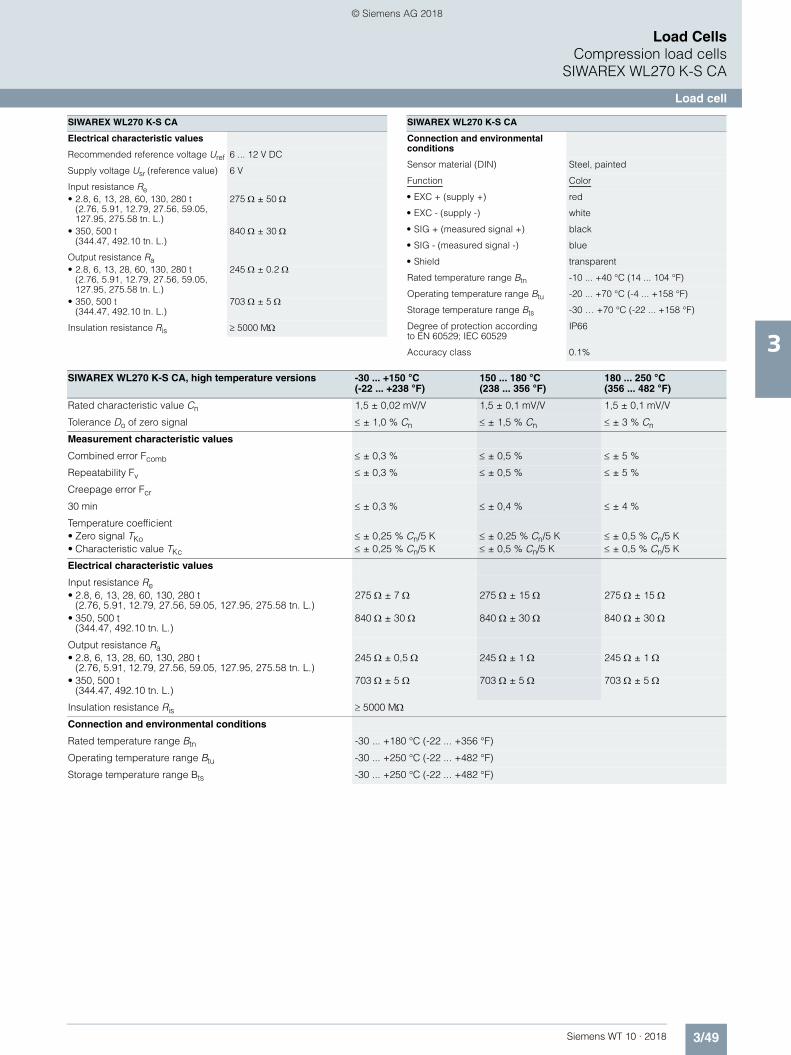
3/49Siemens WT 10 · 2018
Load CellsCompression load cells
SIWAREX WL270 K-S CA
Load cell
3
Electrical characteristic values
Recommended reference voltage Uref 6 ... 12 V DC
Supply voltage Usr (reference value) 6 V
Input resistance Re• 2.8, 6, 13, 28, 60, 130, 280 t
(2.76, 5.91, 12.79, 27.56, 59.05, 127.95, 275.58 tn. L.)
275 ± 50
• 350, 500 t(344.47, 492.10 tn. L.)
840 ± 30
Output resistance Ra• 2.8, 6, 13, 28, 60, 130, 280 t
(2.76, 5.91, 12.79, 27.56, 59.05, 127.95, 275.58 tn. L.)
245 ± 0.2
• 350, 500 t(344.47, 492.10 tn. L.)
703 ± 5
Insulation resistance Ris 5000 M
SIWAREX WL270 K-S CA
Connection and environmental conditions
Sensor material (DIN) Steel, painted
Function Color
• EXC + (supply +) red
• EXC - (supply -) white
• SIG + (measured signal +) black
• SIG - (measured signal -) blue
• Shield transparent
Rated temperature range Btn -10 ... +40 °C (14 ... 104 °F)
Operating temperature range Btu -20 ... +70 °C (-4 ... +158 °F)
Storage temperature range Bts -30 … +70 °C (-22 ... +158 °F)
Degree of protection according to EN 60529; IEC 60529
IP66
Accuracy class 0.1%
SIWAREX WL270 K-S CA
SIWAREX WL270 K-S CA, high temperature versions -30 ... +150 °C (-22 ... +238 °F)
150 ... 180 °C (238 ... 356 °F)
180 ... 250 °C (356 ... 482 °F)
Rated characteristic value Cn 1,5 ± 0,02 mV/V 1,5 ± 0,1 mV/V 1,5 ± 0,1 mV/V
Tolerance Do of zero signal ± 1,0 % Cn ± 1,5 % Cn ± 3 % Cn
Measurement characteristic values
Combined error Fcomb ± 0,3 % ± 0,5 % ± 5 %
Repeatability Fv ± 0,3 % ± 0,5 % ± 5 %
Creepage error Fcr
30 min ± 0,3 % ± 0,4 % ± 4 %
Temperature coefficient• Zero signal TKo ± 0,25 % Cn/5 K ± 0,25 % Cn/5 K ± 0,5 % Cn/5 K• Characteristic value TKc ± 0,25 % Cn/5 K ± 0,5 % Cn/5 K ± 0,5 % Cn/5 K
Electrical characteristic values
Input resistance Re• 2.8, 6, 13, 28, 60, 130, 280 t
(2.76, 5.91, 12.79, 27.56, 59.05, 127.95, 275.58 tn. L.)275 ± 7 275 ± 15 275 ± 15
• 350, 500 t(344.47, 492.10 tn. L.)
840 ± 30 840 ± 30 840 ± 30
Output resistance Ra• 2.8, 6, 13, 28, 60, 130, 280 t
(2.76, 5.91, 12.79, 27.56, 59.05, 127.95, 275.58 tn. L.)245 ± 0,5 245 ± 1 245 ± 1
• 350, 500 t(344.47, 492.10 tn. L.)
703 ± 5 703 ± 5 703 ± 5
Insulation resistance Ris 5000 M
Connection and environmental conditions
Rated temperature range Btn -30 ... +180 °C (-22 ... +356 °F)
Operating temperature range Btu -30 ... +250 °C (-22 ... +482 °F)
Storage temperature range Bts -30 ... +250 °C (-22 ... +482 °F)
WT10-2018_en_Kap03.book Seite 49 Dienstag, 5. Juni 2018 11:50 11
© Siemens AG 2018

3/50 Siemens WT 10 · 2018
Load CellsCompression load cellsSIWAREX WL270 K-S CA
Load cell
3
■ Selection and ordering data 1 2 Article No. Article No.
1) Heat-resistant cable: -60 … +180 °C (-76 … +356 °F). The cable for high temperatures versions is heat resistant to 250 °C (238 °F).2) Can be ordered from 13 t (12.79 tn. L.).
SIWAREX WL270 K-S CA load cell 7MH5114-
Accuracy class 0.1%Heat-resistant connecting cable1)
■ ■ L ■ ■
Click on the Article No. for the online configuration in the PIA Life Cycle Portal.
Rated load Cable length
• 2,8 t (2.76 tn. L.) 6 m (19.68 ft) 4 J
• 6 t (5.91 tn. L.) 6 m (19.68 ft) 4 Q
• 13 t (12.79 tn. L.) 15 m (49.21 ft) 5 D
• 28 t (27.56 tn. L.) 15 m (49.21 ft) 5 J
• 60 t (59.05 tn. L.) 15 m (49.21 ft) 5 Q
• 130 t (127.95 tn. L.) 20 m (65.62 ft) 6 D
• 280 t (275.58 tn. L.) 20 m (65.62 ft) 6 J
• 350 t (244.47 tn. L.) 25 m (65.62 ft) 6 L
• 500 t (492.10 tn. L.) 25 m (65.62 ft) 6 P
Explosion protection
None 0 0
Explosion protection for zones 2, 22 0 1
Options
Double bridge2)
Load cell, redundant design, without explosion protection
6 0
High temperature2)
Temperature range -30 °C … +250 °C (-22 °F … +482 °F), accuracy varies over temperature range, cables and components designed for tempera-ture range, without explosion protection.
7 0
Double bridge and high temperature2)
Redundant design load cell, temperature range -30 °C … +250 °C (-22 °F … +482 °F), accuracy varies over temperature range, cables and components designed for temperature range, without explosion protection.
8 0
SIWAREX WL270 K-S CA load cell 7MH5114-
Accuracy class 0.1%Heat-resistant connecting cable1)
■ ■ L ■ ■
WT10-2018_en_Kap03.book Seite 50 Dienstag, 5. Juni 2018 11:50 11
© Siemens AG 2018

3/51Siemens WT 10 · 2018
Load CellsCompression load cells
SIWAREX WL270 K-S CA
Load cell
3
■ Dimensional drawings
SIWAREX WL270 K-S CA load cell, dimensions in mm (inch)
Rated load [t (tn. L.)]
k
F
aa
HL
ØD
Ød
2xR
8(0.31)12(0.47)14(0.55)20(0.78)26(1.02)45(1.77)40(1.58)47(1.85)
2,8, 6 (2.76, 5.91)13 (12.79)28 (27.56)60 (59.05)130 (127.95)280 (275.58)350 (344.47)500 (492.10)
a ød øD
45(1.77)55(2.16)64(2.51)90(3.54)121(4.76)165(6.5)192(7.95)236(9.29)
H
40(1.57)44(1.73)46(1.81)50(1.96)64(2.51)90(3.14)139(6.30)164(7.13)
F
20(0.59)20(0.59)20(0.59)20(0.59)20(0.59)20(0.59)50.5(1.97)99.5(1.97)
L
56(2.2)68(2.67)74(2.91)90(3.54)116(4.56)170(6.7)240(9.45)275(10.83)
R
50(1.96)66(2.6)72(2.83)100(3.93)125(4.92)183(7.2)325(12.80)450(17.72)
k
16.7(0.65)24,5(0.96)36(1.41)52,7(2.07)77,5(3.05)114(4.48)132(5.20)155(6.10)
40,5(1.59)45,5(1.79)50(1.89)63(2.48)78,5(3.09)100,5(3.96)124(5.00)1465.67)
WT10-2018_en_Kap03.book Seite 51 Dienstag, 5. Juni 2018 11:50 11
© Siemens AG 2018

3/52 Siemens WT 10 · 2018
Load CellsCompression load cellsSIWAREX WL270 K-S CA
Load cell
3
SIWAREX WL270 K-S CA load cell, with double bridge, dimensions in mm (inch)
Rated load [t (tn.L.)]
12(0.47)14(0.55)20(0.78)26(1.02)45(1.77)40(1.58)47(1.85)
13 (12.79)
28 (27.56)
60 (59.05)
130 (127.95)
280 (275.58)
350 (344.47)
500( 492.10)
a ød øD
55(2.16)64(2.51)90(3.54)121(4.76)165(6.5)192(7.95)236(9.29)
H
44(1.73)46(1.81)50(1.96)64(2.51)90(3.14)139(6.30)164(7.13)
F
20(0.79)20(0.79)20(0.79)20(0.79)20(0.79)50.5(1.97)99.5(1.97)
k
45,5(1.79)50(1.88)63(2.48)78,5(3.09)100.5(3.96)124(5.00)146(5.67)
L
68(2.67)74(2.91)90(3.54)116(4.56)170(6.7)240(9.45)275(10.83)
R
66(2.6)72(2.83)100(3.93)125(4.92)183(7.2)325(12.80)450(17.72)
Ø18
(0.7
1)
2xR
Ød
ØD
L Ha
a
F
k
24,5(0.96)36(1.41)52,7(2.07)77,5(3.05)114(4.48)132(5.20)155(6.10)
WT10-2018_en_Kap03.book Seite 52 Dienstag, 5. Juni 2018 11:50 11
© Siemens AG 2018

3/53Siemens WT 10 · 2018
Load CellsCompression load cells
SIWAREX WL270 K-S CA
Self-aligning bearing
3
■ Overview
The self-centering self-aligning bearing for SIWAREX WL270 K-S CA load cells is particularly suitable for use in container and hopper scales.
■ Design
The self-aligning bearing comprises two pressure plates.
Together with the load cell, the pressure plates form a self-cen-tering unit. This allows the top plate, and thus the load bearing implement, to accommodate horizontal displacements (e.g. due to temperature fluctuations). The design of the self-aligning bearing creates a restoring force which is dependent on the size of the displacement and the applied load.
If the load bearing implement is displaced by more than value s (see dimensional drawing table) in the horizontal direction, mea-sures for restricting sideways play (e.g. stops) must be provided in the construction of the load bearing implement. Lifting of the load bearing implement must be prevented by suitable mea-sures provided in the construction of the load bearing imple-ment.
The load cell is not included in the scope of delivery of the self-aligning bearing.
Heavy load versions
Suitable mounting units are also available for heavy load cells with 350 and 500 t (344.47 and 492.10 tn. L.) rated loads. These are also designed as self-centering, self-aligning bearings.
■ Technical specifications
■ Selection and ordering data 1 2Article No.
Pressure plate for load cell type SIWAREX WL270 K-S CA
Rated load t (tn. L.) 2.8 (2.76) 6 (5.91) 13 (12.80) 28 (27.56) 60 (59.10) 130 (127.95) 280 (275.88)
Permissible lateral deflection in mm (inch):
2 (0.08) 2 (0.08) 2.5 (0.10) 2.5 (0.10) 3 (0.12) 4 (0.16) 6 (0.24)
Rated measuring path hn at Emax mm (inch)
0.23 (0.009) 0.35 (0.014) 0.53 (0.021) 0.80 (0.032) 1.22 (0.048) 1.85 (0.073) 2.67 (0.11)
1) The load cell is not included in the scope of delivery.2) Use of a grounding cable (7MH3701-1AA1) to protect the load cell is highly recommended.
Pressure plate1)2)
For SIWAREX WL270 K-S CA load cells 2 pressure plates are required to set up a self-aligning bearing, one each at the top and bottom respectively.
Material: Steel, painted
For load cells with a rated load of
• 2,8, 6 t (2.76, 5.91 tn. L.) 7MH3115-3AA1
• 13 t (12.79 tn. L.) 7MH3115-1BA1
• 28 t (27.56 tn. L.) 7MH3115-2BA1
• 60 t (59.05 tn. L.) 7MH3115-3BA1
• 130 t (127.95 tn. L.) 7MH3115-1CA1
• 280 t (275.58 tn. L.) 7MH3115-2CA1
• 350 t (344.47 tn. L.) 7MH5714-6LD10
• 500 t (492.10 tn. L.) 7MH5714-6PD10
WT10-2018_en_Kap03.book Seite 53 Dienstag, 5. Juni 2018 11:50 11
© Siemens AG 2018

3/54 Siemens WT 10 · 2018
Load CellsCompression load cellsSIWAREX WL270 K-S CA
Self-aligning bearing
3
■ Dimensional drawings
Self-aligning bearing for SIWAREX WL270 K-S CA load cells, dimensions in mm (inch)
Ø6,5
100 ± 0,5/-1
120 ± 0,5/-1
136 ± 0,5/-1
174 ± 0,5/-1
220 ± 0,5/-1
300 ± 0,6/-1,2
390 (15.35)
490 (19.29)
2 (0.08)
2.5 (0.98)
2.5 (0.98)
3 (0.12)
4 (0.16)
6 (0.24)
6 (0.24)
6 (0.24)
Rated load [t]
Rated load [t]
s (allowed sideways displacement)
Øa
Øc
de
h
Øg
k
Øb
63 (2.48)
73 (2.87)
84 (3.31)
112 (4.41)
148 (5.83)
190 (7.48)
200 (7.87)
240 (9.45)
87 (3.43)
97 (3.82)
108 (4.25)
137 (5.39)
176 (6.93)
226 (8.90)
240 (9.45)
280 (11.02)
2,8, 6
13
28
60
130
280
350
500
øa øc
11 (0.43)
11 (0.43)
11 (0.43)
11 (0.43)
11 (0.43)
14 (0.55)
26 (1.02)
26 (1.02)
d
14 (0.55)
21 (0.83)
-
-
-
-
-
-
e
25 (0.98)
32 (1.26)
28 (1.10)
42 (1.65)
52 (2.05)
65 (2.56)
30 (1.18)
45 (1.77)
18 (0.71)
18 0.71)
-
-
-
-
-
-
2,8, 6
13
28
60
130
280
350
500
øg h k
øb
2 x 180°
2 x 180°
2 x 180°
4 x 90°
4 x 90°
2 x 180°
2 x 180°
2 x 180°
WT10-2018_en_Kap03.book Seite 54 Dienstag, 5. Juni 2018 11:50 11
© Siemens AG 2018

3/55Siemens WT 10 · 2018
Load CellsRing torsion load cells
3
■ Overview
Type Ring torsion
Possible applications Hopper and belt scales, platform weighing machines and roller table scales
Example picture
Series WL280 RN-S SA
Rated load Emax 60 … 280 kg (132.28 ... 617.29 lb) 0,5 … 10 t (0.49 ... 9.84 tn. L.) 13 … 60 t (12.79 ... 59.05 tn. L.)
Accuracy class C3
Max. load cell verification interval (nIC)
3 000
Min. load cell verification interval (Vmin)
Emax/16 000 Emax/17 500 Emax/17 500
Supply voltage (Usr) 5 ... 30 V
Rated characteristic value 1 mV/V 2 mV/V 2 mV/V
Degree of protection IP66/IP68
Material Stainless steel
Ex protection according to ATEX (optional)
II 1 G Ex ia IIC T4 GaII 1 D Ex ia IIIC T73 °C DaII 3 G Ex ic IIC T4 GcII 3 G Ex nA IIC T4 GcII 3 D Ex tc IIIC T63 °C Dc
WT10-2018_en_Kap03.book Seite 55 Dienstag, 5. Juni 2018 11:50 11
© Siemens AG 2018

3/56 Siemens WT 10 · 2018
Load CellsRing torsion load cellsSIWAREX WL280 RN-S SA
Load cell
3
■ Overview
The ring torsion load cell is particularly suitable for use in container, conveyor, platform and roller table scales.
■ Design
The measurement element is a ring torsion spring made of stain-less steel. Two strain-gage spirals (DMS) are applied to the up-per and lower faces of the ring respectively. The spring element is deformed by the load acting centrically in the measurement direction. This compresses the strain-gage of the upper face of the ring and extends the strain-gage on the lower face of the ring. This causes a change in the electrical resistance of the force-locked strain-gage, which is detected by means of a bridge circuit.
All load cells with a rated load of up to 13 t (12.79 tn. L.) are equipped with an integral overload protection.
■ Technical specifications
SIWAREX WL280 RN-S SA load cells
Possible applications Container, conveyor, platform and roller table scales
Model Ring torsion load cell
Rated load/maximum load Emax. • 60 kg (132.28 lb)• 130 kg (286.60 lb)• 280 kg (617.29 lb)
• 0.5 t (0.49 tn. L.)• 1 t (0.98 tn. L.)• 2 t (1.97 tn. L.)• 3.5 t (3.45 tn. L.)• 5 t (4.92 tn. L.)• 10 t (9.84 tn. L.)
• 13 t (12.80 tn. L.)• 28 t (27.56 tn. L.)• 60 t (59.05 tn. L.)
Accuracy class according to OIML R60 C3
Max. load cell verification intervals nLC 3 000
Min. load cell verification intervals Vmin Emax/16 000 Emax/17 500
Minimum application range Rmin(LC) 19 % 17 %
Combined error Fcomb ± 0.023 % Cn
Repeatability Fv ± 0.01 % Cn
Return of zero signal ± 0.0167 % Cn1)
Creep error Fcr• 30 min ± 0.0245 % Cn
1)
• 20 … 30 min ± 0.0053 % Cn1)
Temperature coefficient• Zero signal TKo ± 0.004 % Cn/5K • Characteristic value TKc ± 0.004 % Cn/5K
Min. dead load Emin ± 0 % Emax
Safe load limit Lu 200 % Emax 150 % Emax
Ultimate load Ld 500 % Emax 300 % Emax 300 % Emax
Safe side load LIq 75 % Emax 100 % Emax 75 % Emax
Rated measuring path hn at Emax 0.07 mm 0.1 ± 0.02 mm 0.11 … 0.2 mm
Overload protection Integrated Integrated Integrated at 13 t
Supply voltage Usr (reference value) 15 V 10 V 15 V
Supply voltage (range) 5 … 30 V+
Rated characteristic value Cn 1 mV/V 2 mV/V 2 mV/V
Tolerance Dc of characteristic value Up to 500 kg: 0.01 mV/Vfrom 500 kg: 0.1 mV/V
WT10-2018_en_Kap03.book Seite 56 Dienstag, 5. Juni 2018 11:50 11
© Siemens AG 2018

3/57Siemens WT 10 · 2018
Load CellsRing torsion load cells
SIWAREX WL280 RN-S SA
Load cell
3
1 2
■ Selection and ordering data Article No.
Tolerance Do of zero signal ± 1.0 % Cn
Input resistance Re 60 kg: 1260 ± 100 130 kg: 1260 ± 100 280 kg: 1260 ± 250
1100 ± 100 13 t: 1200 ± 100 28 t: 1075 ± 100 60 t: 1350 ± 200
Output resistance Ra 1020 ± 0.5 1025 ± 25 13 t: 1000 ± 0.5 28 t: 930 ± 0.5 60 t: 1175 ± 0.5
Insulation resistance Ris 5 000 M 5 000 M 5 000 M
Rated temperature range Btn -10 … +40 °C (14 ... 104 °F)
Operating temperature range Btu -35 … +70 °C (-31 ... 158 °F)
Storage temperature range Bts -50 … +90 °C (-58 ... 194 °F)
Sensor material (DIN) Stainless steel, mat. no. 14542
Degree of protection according to EN 60529; IEC 60529 IP66/68
Recommended tightening torque of the fixing screws 8 Nm 14 Nm (0.5 … 5 t)
10 Nm (10 t)
-
Current calibration2) Standard
Ex protection to ATEX (optional) II 1 G Ex ia IIC T4 GaII 1 D Ex ia IIIC T73 °C DaII 3 G Ex ic IIC T4 GcII 3 G Ex nA IIC T4 GcII 3 G Ex tc IIIC T63 °C Dc
Cable connection
Function Color
• EXC + pink
• EXC - gray
• SIG + brown
• SIG - white
• Screening transparent
1) For rated temperature -10 ... +40 °C (14 ... 104 °F)2) Current calibration: rated characteristic value and output resistance are adjusted so that the output current is calibrated within 0.05 % of a reference value.
This makes it easier to connect several load cells in parallel.
SIWAREX WL280 RN-S SA load cells
SIWAREX WL280 RN-S SA load cell 7MH5113-
Stainless steel, low mounting height, IP66/68accuracy class C3 according to OIML R60
■ ■ D 0 ■
Click on the Article No. for the online configuration in the PIA Life Cycle Portal.
Rated load Cable length
• 60 kg (132.28 lb) 3 m (9.84 ft) 2 Q
• 130 kg (286.60 lb) 3 m (9.84 ft) 3 D
• 280 kg (617.29 lb) 3 m (9.84 ft) 3 J
• 500 kg (1 102.31 lb) 3 m (9.84 ft) 3 P
• 1 t (0.98 tn. L.) 3 m (9.84 ft) 4 A
• 2 t (1.97 tn. L.) 6 m (19.68 ft) 4 G
• 3,5 t (3.44 tn. L.) 6 m (19.68 ft) 4 L
• 5 t (4.92 tn. L.) 6 m (19.68 ft) 4 P
• 10 t (9.84 tn. L.) 15 m (49.21 ft) 5 A
• 13 t (12.79 tn. L.) 15 m (49.21 ft) 5 D
• 28 t (27.56 tn. L.) 15 m (49.21 ft) 5 J
• 60 t (59.05 tn. L.) 15 m (49.21 ft) 5 Q
Explosion protection
None 0
Explosion protection for zones 1, 2, 20, 21, 22 1
WT10-2018_en_Kap03.book Seite 57 Dienstag, 5. Juni 2018 11:50 11
© Siemens AG 2018
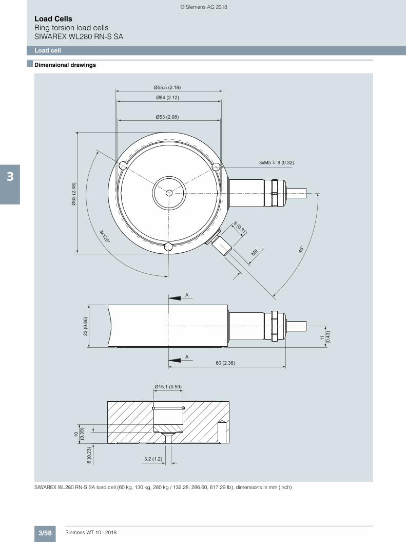
3/58 Siemens WT 10 · 2018
Load CellsRing torsion load cellsSIWAREX WL280 RN-S SA
Load cell
3
■ Dimensional drawings
SIWAREX WL280 RN-S SA load cell (60 kg, 130 kg, 280 kg / 132.28, 286.60, 617.29 lb), dimensions in mm (inch)
Ø15.1 (0.59)
3.2 (1.2)
Ø55.5 (2.18)
Ø54 (2.12)
Ø53 (2.08)
Ø63
(2.4
8)
60 (2.36)A
A
3xM5 8 (0.32)
8 (0.31)
M6 45°
3x120°
10
(0.3
9)
11
(0.4
3)22 (0
.86)
6 (0
.23)
WT10-2018_en_Kap03.book Seite 58 Dienstag, 5. Juni 2018 11:50 11
© Siemens AG 2018

3/59Siemens WT 10 · 2018
Load CellsRing torsion load cells
SIWAREX WL280 RN-S SA
Load cell
3
SIWAREX WL280 RN-S SA load cell (0,5 t, 1 t / 0.49, 0.98 tn. L.), dimensions in mm (inch)
12.5
(0.4
9)
10
(0.4
)
3 x M6 8 (0.32)
Ø70 (2.75)
3 x
120°
Ø69
(2.7
1)
Ø71
(2.8
)
Ø80
(3.1
5)
25 (0
.98)
A
A
65 (2.56)
1 (0
.04)
18 (0
.7)
24 (0
.94)
M10
Ø25 (0.98)
Ø19 (0.75)
WT10-2018_en_Kap03.book Seite 59 Dienstag, 5. Juni 2018 11:50 11
© Siemens AG 2018

3/60 Siemens WT 10 · 2018
Load CellsRing torsion load cellsSIWAREX WL280 RN-S SA
Load cell
3
SIWAREX WL280 RN-S SA load cell (2 t, 3 t, 5 t / 1.97, 2.95, 4.92 tn. L.), dimensions in mm (inch)
12.5
(0.4
9)
10
(0.3
9)
Ø71
(2.8
0)
Ø69
(2.7
2)
Ø80
(3.1
5)
65 (2.56)
18
(0.7
1)
24 (0
.94)
Ø25 (0.98)
Ø19 (0.75)
3 x M6 8 (0.32)
3 x
120°
30 (1
.18)
A
A
6 (0
.23)
Ø15(0.59)
WT10-2018_en_Kap03.book Seite 60 Dienstag, 5. Juni 2018 11:50 11
© Siemens AG 2018

3/61Siemens WT 10 · 2018
Load CellsRing torsion load cells
SIWAREX WL280 RN-S SA
Load cell
3
SIWAREX WL280 RN-S SA load cell (10 t / 9.84 tn. L.), dimensions in mm (inch)
12.5
(0.4
9)
31.2
(1.2
)
20.7
(0.8
2)40 (1
.57)
Ø26 (1.02)
Ø29 (1.14)
3 x M6 8 (0.32)
Ø83 (3.27)
3 x
120°
Ø75
(2.9
5)
Ø72
(2.8
4)
Ø95
(3.7
4)
35 (1
.38)
A
A
72 (2.83)
WT10-2018_en_Kap03.book Seite 61 Dienstag, 5. Juni 2018 11:50 11
© Siemens AG 2018

3/62 Siemens WT 10 · 2018
Load CellsRing torsion load cellsSIWAREX WL280 RN-S SA
Load cell
3
SIWAREX WL280 RN-S SA load cell (13 t / 12.79 tn. L.), dimensions in mm (inch)
31.2
(1.2
2)
Ø79.5 (3.12)
Ø24.9 (0.98)
Ø76.5 (3)
A
A
20
(0.7
8)
35 (1
.37)
20 (0
.78)
40 (1
.57)
45°
M6
Ø95 (3.74)
Ø29 (1.14)
Ø26 (1.02)
85 (3.35)
8 (0.31)
WT10-2018_en_Kap03.book Seite 62 Dienstag, 5. Juni 2018 11:50 11
© Siemens AG 2018

3/63Siemens WT 10 · 2018
Load CellsRing torsion load cells
SIWAREX WL280 RN-S SA
Load cell
3
SIWAREX WL280 RN-S SA load cell (28 t, 60 t / 27.56, 59.05 tn. L.), dimensions in mm (inch)
Rated load[t]
35.9(1.41)47.9(1.88)
C
A
A
ØF
8(3.14)
M6
40°
D
E
B
ØG
ØH
7 (0
.27)
ØA
28
60
øA B
25(0.98)34(1.33)
C
94(3.7)105(4.13)
D
46(1.8)62(2.44)
E
53(2.08)69(2.71)
øF
120(4.72)140(5.5)
øG
102(4)124(4.88)
øH
98(3.85)120(4.72)
R
R400
R600
WT10-2018_en_Kap03.book Seite 63 Dienstag, 5. Juni 2018 11:50 11
© Siemens AG 2018

3/64 Siemens WT 10 · 2018
Load CellsRing torsion load cellsSIWAREX WL280 RN-S SA
Mounting unit and guide element
3
■ Overview
SIWAREX WL280 RN-S SA mounting unit and guide element, front
SIWAREX WL280 RN-S SA mounting unit and guide element, rear
The mounting unit, together with the load cells of the SIWAREX WL280 RN-S SA series, form a self-centering unit. The guide elements prevent a container, for example, from moving sideways due to an external lateral force. The guide elements can be mounted on one or both sides of the mounting unit.
■ Design
The mounting unit comprises a base plate and a top plate, a thrust pad with a flat gasket and a pendulum support. A very flexible grounding cable between the top and base plate con-ducts any fault currents past the load cell. The top plate is con-nected to the base plate by means of two countersunk head screws. On both sides of the base and top plate there are threaded holes for the later flange-fitting of guide elements.
The top plate is fixed above the base plate by means of two countersunk head screws. This results in a single unit that is eas-ily handled. The top plate must be precisely aligned above the base plate. The height of the top plate is set so that it is 2 milli-meters (for the 60 ... 280 kg version) or 3 millimeters (for the 0.5 ... 13 t versions) above the installation height with load cell.
In this state the mounting unit serves as an installation aid and can be used as a dummy for lighter installation jobs.
The load cell, together with the pendulum support and the thrust pad, can be inserted into the mounting unit. Load cell and thrust pad are secured with clamping washers.
The load cell can be inserted in the scale before installing the mounting unit. In the same way, it is possible to insert the load cell after installation in the mounting unit.
The fixing holes of the mounting unit are 6 mm wider in diameter than the necessary fixing screws. This means that a greater tolerance error is permissible in the connection measurements. The mounting unit is clamped tightly using the washers supplied.
After the mounting units have been mounted in the scales, the load bearing element is ideally aligned. The load cells are not yet loaded. Finally, the load bearing implement is lowered by loos-ening the hexagonal bolts under the top plate. The weight now rests on the load cells.
In this state the load cell and the mounting unit together form a self-centering bearing unit. The mounting unit allows the top plate (and thus the load bearing implement) to be displaced up to two millimeters (for the 60 ... 280 kg version) or three millime-ters (for the 0.5 ... 13 t versions) to the side in all directions. The countersunk head screws prevent the load bearing element from being lifted off or tipping up. The countersunk head screws se-cure the load bearing element against sharp lateral movement on the occurrence of sporadic transverse forces.
By using the mounting unit as an installation aid, the load cells are optimally aligned. This is absolutely essential for the best uti-lization of the load cells in terms of accuracy. In the event of maintenance or a fault, the load cell can be released again by undoing the hexagonal nuts. After loosening the clamping wash-ers, the cell can then easily be replaced.
Guide elements are used if the lateral movement of a load bear-ing element is to be prevented. The lateral movements can be initiated by agitator start-up in a container, by braking or accel-erating forces in a roller conveyor or though forces exerted by the wind on outdoor silos.
A guide element consists of two flanges and one clamping screw. The clamping screw is adjusted to the correct length. The guide element is attached to the operational mounting unit. A guide unit can be mounted on the front or rear of the mounting unit. If necessary, two guide elements can be used in parallel in order to double the transferrable lateral force.
In the case of scales with four load cells, only three mounting units may be equipped with guide units.
Shims are used to compensate for angular errors in the lugs. If more than three load cells are used, the shims are also used to adjust the height of the lugs.
WT10-2018_en_Kap03.book Seite 64 Dienstag, 5. Juni 2018 11:50 11
© Siemens AG 2018

3/65Siemens WT 10 · 2018
Load CellsRing torsion load cells
SIWAREX WL280 RN-S SA
Mounting unit and guide element
3
■ Selection and ordering data1 Article No. ■ Dimensional drawings
WL280 mounting unit
WL280 guide element
1) The load cell and the compact mounting unit are not included in the scope of delivery.
Mounting unitsFor SIWAREX WL280 RN-S SA load cells
Material: Stainless steel
For load cells with a rated load of1)
• 60 ... 280 kg (132.28 ... 617.29 lb)
7MH5713-3JA00
• 0,5 ... 1 t (0.49 ... 0.98 tn. L.) 7MH5713-4AA00
• 2 ... 5 t (1.97 ... 4.92 tn. L.) 7MH5713-4PA00
• 10 ... 13 t (9.84 ... 12.80 tn. L.) 7MH5713-5DA00
Guide elements (optional)for mounting units of the SIWAREX WL280 RN-S SA series
Material: Stainless steel
For load cells with a rated load of
• 60 ... 280 kg (132.28 ... 617.29 lb);Permitted transverse force: 1,5 kN
7MH5713-3JE00
• 0,5 ... 1 t (0.49 ... 0.98 tn. L.);Permitted transverse force: 2,5 kN
7MH5713-4AE00
• 2 ... 5 t (1.97 ... 4.92 tn. L.);Permitted transverse force: 5 kN
7MH5713-4PE00
• 10 ... 13 t (9.84 ... 12.80 tn. L.);Permitted transverse force: 10 kN
7MH5713-5DE00
Shims (accessories)For mounting units of the SIWAREX WL280 RN-S SA series
Material: Stainless steel
For load cells with a rated load of1)
• 60 ... 280 kg (132.28 ... 617.29 lb);Contents: 16 units, each 0.5 mm thick
7MH5713-3JG00
• 0.5 ... 1 t (0.49 ... 0.98 tn. L.);Contents: 24 units, each 0.5 mm thick
7MH5713-4AG00
• 2 ... 5 t (1.97 ... 4.92 tn. L.);Contents: 4 units each 0.5 mm thick, 16 units each 1 mm thick
7MH5713-4PG00
• 10 ... 13 t (9.84 ... 12.80 tn. L.);Contents: 4 units each 0.5 mm thick, 20 units each 1 mm thick
7MH5713-5DG00
EE
GG
FØ H
ØJ
DB
A
C
G_W
T01_
XX
_101
40
60 ... 280 kg1366016690126014.5913.5
ABCDEFGØ HØ J
0.5 t / 1 t165752001101585181117.5
2 t ... 5 t185752201102095231117.5
10 t / 13 t2009024013020127.22413.520
AB
CD
G_W
T01_
XX
_101
41
60 ... 280 kg1666010~30.5
ABCD
0,5 t / 1 t2008512~35
2 t ... 5 t2209518~45.5
10 t / 13 t240127.218~54.4
WT10-2018_en_Kap03.book Seite 65 Dienstag, 5. Juni 2018 11:50 11
© Siemens AG 2018

3/66 Siemens WT 10 · 2018
Load CellsLoad cell accessories
Junction box SIWAREX JB
3
■ Overview
SIWAREX JB junction box, aluminum steel
SIWAREX JB junction box, stainless steel
The JB junction box in aluminum or in stainless steel is required for parallel connection of load cells. A maximum of 4 load cells can be connected to one junction box.
Only for junction boxes in aluminum:
If more than 4 load cells are to be connected, a second junction box must be connected in parallel via a cross connection. An ex-pansion set is required for this purpose. The cross-connection can be used to connect up to three load cells in the first junction box. Up to four load cells can be connected in the second junc-tion box.
■ Design
The junction box of die-cast aluminum consists of a lower sec-tion and cover. The enclosure is dust-protected and splashproof according to IP66 degree of protection. The cables are fed in through metric cable glands. In the enclosure, screw terminals are fixed onto a connection board.
Internal resistance, characteristic value and rated load of all par-allel-switched load cells must be identical. The value of these variables is not limited by the junction box. Load cells can be connected in 4-wire or 6-wire systems.
For 6-wire systems, two jumpers must also be separated.
Connection examples
Four load cells
LC: Load cell JB: Junction box in aluminum or stainless steel
Eight load cells
LC: Load cell JB: Only for junction boxes in aluminum
■ Technical specifications
SIWAREX JB junction box, aluminum and stainless steel enclosure
Cable glands• Of load cells 4 x M16• Of signal cable 1 x M20
Permissible ambient temperature• During operation -50 ... +80 °C (-58 ... 176 °F)• During operation for legal-for-trade
medium accuracy weighing machine
-10 ... +40 °C (14 ... 104 °F)
• During transportation and storage -50 ... +100 °C (-58 ... 212 °F)
Degree of protection IP66 to EN 60529
Vibration resistance of terminals to DIN VDE 0611 11/77
10 Hz and 150 Hz, amplitude 0.35 mm
SIWAREX weighing system
Max. cable length: see technical specifications of weighing module
LC
LC
LC
LC
6
4/6
JB
SIWAREX weighing system
LC
LC
LC
LC
LC
LC
LC
6
6
4/6
JB
JB
WT10-2018_en_Kap03.book Seite 66 Dienstag, 5. Juni 2018 11:50 11
© Siemens AG 2018

3/67Siemens WT 10 · 2018
Load CellsLoad cell accessories
Junction box SIWAREX JB
3
■ Selection and ordering data Article No. ■ Dimensional drawings
SIWAREX JB junction box in aluminum (7MH5001-0AA20), dimensions in mm (inches)
SIWAREX JB junction box in stainless steel (7MH5001-0AA01), dimensions in mm (inches)
SIWAREX JB junction box, aluminum housingFor connecting up to 4 load cells in parallel, and for connecting several junction boxes
7MH5001-0AA20
SIWAREX JB junction box, stainless steel housingFor connecting up to 4 load cells in parallel
7MH5001-0AA01
SIWAREX JB junction box, stainless steel housing (ATEX)For connecting up to 4 load cells in parallel(For zone allocation, see manual or type examination certificate)
7MH4710-1EA01
Cable (optional)
Cable Li2Y 1 x 2 x 0.75 ST + 2 x (2 x 0.34 ST) – CY
For connecting SIWAREX elec-tronic weighing systems to junc-tion box (JB), extension box (EB) and Ex interface or between two JBs. For permanent installation. Occa-sional bending is possible. External diameter: approx. 10.8 mm (0.43 in) Permissible ambient temperature -40 ... +80 °C (-104 ... +176 °F). Sold by the meter.• Sheath color: orange 7MH4702-8AG• For potentially explosive atmo-
spheres. Sheath color: blue.7MH4702-8AF
81 (3
.19)
66 (2
.6)
100
(3.9
4)
160 (6.3)136 (5.75)
28,5
(1.1
2)
Ø5
(0.2
)12
(0.4
7)23
(0.9
1)
8 (0.31)
6,9 (0.27)
6(0.24)
194 (7.64)
M6
54 (2
.13)
65 (2
.56)
Ø10
(0.3
9)
72 (2
.83)
100
(3.9
4)
176 (6.93)150 (5.91)
WT10-2018_en_Kap03.book Seite 67 Dienstag, 5. Juni 2018 11:50 11
© Siemens AG 2018
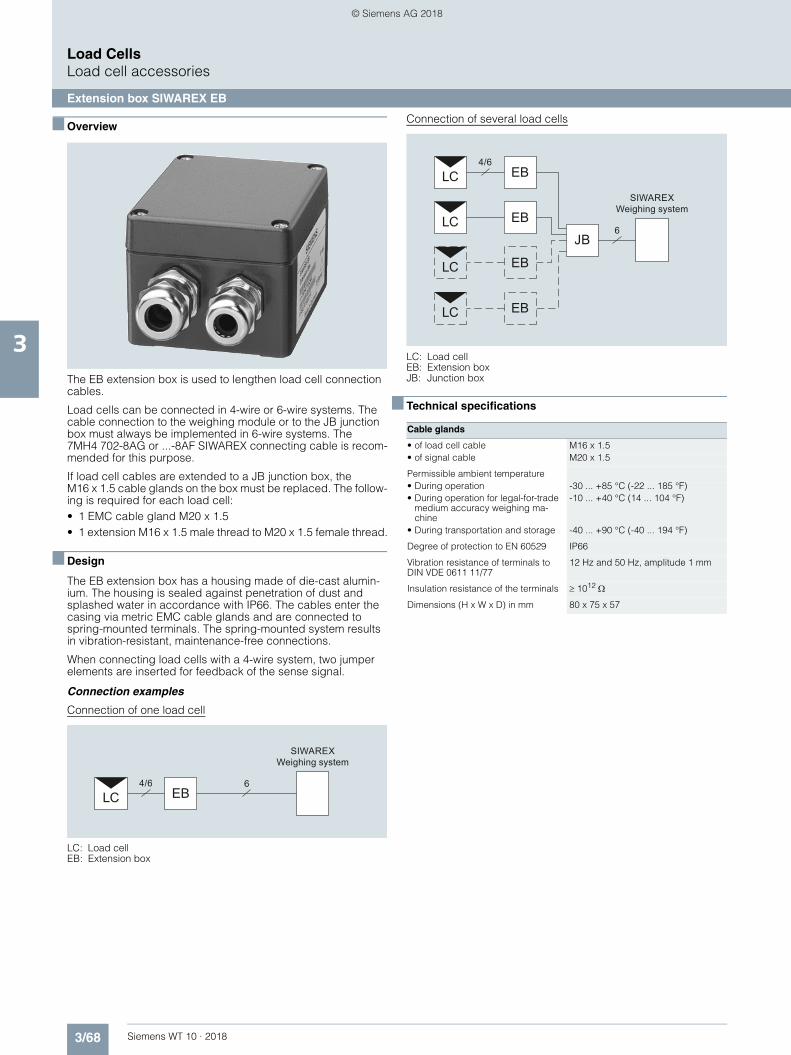
3/68 Siemens WT 10 · 2018
Load CellsLoad cell accessories
Extension box SIWAREX EB
3
■ Overview
The EB extension box is used to lengthen load cell connection cables.
Load cells can be connected in 4-wire or 6-wire systems. The cable connection to the weighing module or to the JB junction box must always be implemented in 6-wire systems. The 7MH4 702-8AG or ...-8AF SIWAREX connecting cable is recom-mended for this purpose.
If load cell cables are extended to a JB junction box, the M16 x 1.5 cable glands on the box must be replaced. The follow-ing is required for each load cell:• 1 EMC cable gland M20 x 1.5• 1 extension M16 x 1.5 male thread to M20 x 1.5 female thread.
■ Design
The EB extension box has a housing made of die-cast alumin-ium. The housing is sealed against penetration of dust and splashed water in accordance with IP66. The cables enter the casing via metric EMC cable glands and are connected to spring-mounted terminals. The spring-mounted system results in vibration-resistant, maintenance-free connections.
When connecting load cells with a 4-wire system, two jumper elements are inserted for feedback of the sense signal.
Connection examples
Connection of one load cell
LC: Load cellEB: Extension box
Connection of several load cells
LC: Load cellEB: Extension boxJB: Junction box
■ Technical specifications
SIWAREX Weighing system
LC64/6
EB
Cable glands
• of load cell cable M16 x 1.5• of signal cable M20 x 1.5
Permissible ambient temperature• During operation -30 ... +85 °C (-22 ... 185 °F)• During operation for legal-for-trade
medium accuracy weighing ma-chine
-10 ... +40 °C (14 ... 104 °F)
• During transportation and storage -40 ... +90 °C (-40 ... 194 °F)
Degree of protection to EN 60529 IP66
Vibration resistance of terminals to DIN VDE 0611 11/77
12 Hz and 50 Hz, amplitude 1 mm
Insulation resistance of the terminals 1012
Dimensions (H x W x D) in mm 80 x 75 x 57
SIWAREX Weighing system
LC
LC
LC
LC
6
4/6EB
EB
EB
EB
JB
WT10-2018_en_Kap03.book Seite 68 Dienstag, 5. Juni 2018 11:50 11
© Siemens AG 2018
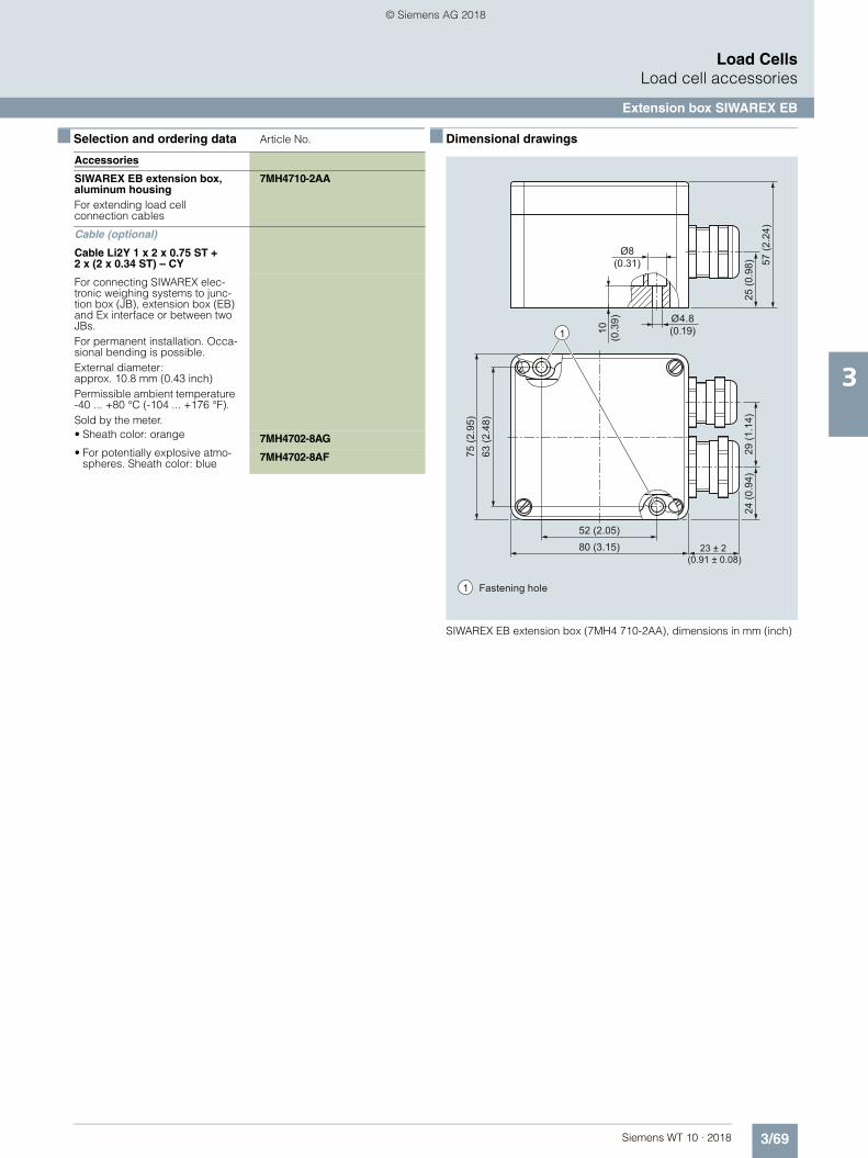
3/69Siemens WT 10 · 2018
Load CellsLoad cell accessories
Extension box SIWAREX EB
3
■ Selection and ordering data Article No. ■ Dimensional drawings
SIWAREX EB extension box (7MH4 710-2AA), dimensions in mm (inch)
Accessories
SIWAREX EB extension box, aluminum housingFor extending load cell connection cables
7MH4710-2AA
Cable (optional)
Cable Li2Y 1 x 2 x 0.75 ST + 2 x (2 x 0.34 ST) – CY
For connecting SIWAREX elec-tronic weighing systems to junc-tion box (JB), extension box (EB) and Ex interface or between two JBs. For permanent installation. Occa-sional bending is possible. External diameter: approx. 10.8 mm (0.43 inch) Permissible ambient temperature -40 ... +80 °C (-104 ... +176 °F). Sold by the meter.• Sheath color: orange 7MH4702-8AG• For potentially explosive atmo-
spheres. Sheath color: blue7MH4702-8AF
1
Fastening hole1
Ø4.8 (0.19)
57 (2
.24)
25 (0
.98)
10
(0.3
9)
52 (2.05)
63 (2
.48)
80 (3.15)
Ø8 (0.31)
23 ± 2 (0.91 ± 0.08)
24 (0
.94)
29 (1
.14)
75 (2
.95)
WT10-2018_en_Kap03.book Seite 69 Dienstag, 5. Juni 2018 11:50 11
© Siemens AG 2018

3/70 Siemens WT 10 · 2018
Load CellsLoad cell accessories
Cables
3
■ Overview
The ultra-flexible grounding cable is for discharging parasitic currents.
■ Design
The grounding cable is 400 mm long and corresponds to an electrical bypass.
It protects the load cell from undesirable voltages which can occur e.g. when welding or as a result of lightning.
We recommend using one grounding cable for each load cell.
The load cell and/or other mounting elements are not included in the scope of delivery of the grounding cable.
■ Selection and ordering data Article No.
■ Dimensional drawings
Grounding cable, dimensions in mm (inch)
Grounding cable made of copperfor discharging parasitic currents
400 mm long 7MH3701-1AA1
Ø10.6 (0.42)
2 (0.08) thick
400 (15.75)
WT10-2018_en_Kap03.book Seite 70 Dienstag, 5. Juni 2018 11:50 11
© Siemens AG 2018

3/71Siemens WT 10 · 2018
Load CellsConfiguration examples
Introduction
3
■ Overview
Number of load cells
The three-point bearing is statically determined and offers a stable setup for any application.
If there are more than three bearing points, the load is likely to be unevenly positioned and, in extreme cases, that two diagonally positioned load cells would have to accommodate the entire load. Three-point bearing should therefore be used wherever possible.
To exclude the possibility of an uneven base, in the case of a bearing with more than three load cells, the prevailing weight distribution on the relevant load cells should be checked and a height adjustment performed if necessary. This can be achieved by using a suitable support to raise the load cells carrying less weight.
Force bypass
Force bypasses are produced if a partial load is transferred past the load cells into the base. There are various reasons for a force bypass (e.g. third-party supports, frictional forces, stresses, etc.).
Force bypasses must be avoided at all costs as they lead to measuring errors.
Rated load of load cells
The rated load is selected under maximum load, taking into account centers of gravity and load distribution on the individual load cells. The rated load is generally selected according to the most heavily loaded load cell. A check also needs to be performed to check if any dynamic forces are superimposed on the static load of the load cell. In this case, the rated load of the load cell must be calculated from the sum of the static load and the peak dynamic force.
The 4 load cells are each loaded with 0.75 t (0.74 tn. L.) in order to ensure even load distribution. During configuration and selection of load cells, approx. 20 % should be added to the calculated rated load for safety reasons. This produces a required load cell rated load of 0.75 t × 1.2 = 0.9 t (0.74 tn. L. x 1.2 = 0.89 tn. L.)
It therefore follows that it is necessary to select the next highest rated load level, with 1 t (0.98 tn. L.).
Example (please also refer to configuration example 1)Even load distribution without dynamic influences
Number of load cellsEmpty weight of containerMaximum capacity
41.2 t (1.18 tn. L.)1.8 t (1.77 tn. L.)
Total load 3 t (2.95 tn. L.)
WT10-2018_en_Kap03.book Seite 71 Dienstag, 5. Juni 2018 11:50 11
© Siemens AG 2018

3/72 Siemens WT 10 · 2018
Load CellsConfiguration examples
Configuration example 1
3
■ Overview
Example 1: Container weighing
The total center of gravity S of the suspended container lies above the level of the load cells.
It is supported on 4 brackets (container manufacturer specifica-tion), has an empty weight (dead load) of 1.2 t (1.18 tn. L.), and a maximum capacity of 1.8 t (1.77 tn. L.). The load is evenly dis-tributed across all 4 load cells.
Note
The three-point bearing of the container is statically determined and represents a stable state (see comment in the introduction).
Selection of load cells and mounting components
The determination of the rated load, as described in the introduction, results in a rated load of 1 t (0.98 tn. L.).
For the above example, 4 SIWAREX WL280 RN-S SA load cells were used with a rated load of 1 t (0.98 tn. L.) because the high-quality WL280 RN-S SA precision load cells have an extremely low constructional height.
Self-centering compact mounting units are used as mounting components because, in addition to their oscillation function and oscillation limitation, they are also fitted with anti-lift protection. The anti-lift protection can absorb a maximum vertical force of 4.2 kN. In the event of greater lifting forces (e.g due to wind load), the container must be safeguarded with additional ca-tastrophe protection.
Container on SIWAREX WL280 RN-S SA load cells and compact mounting units
Configurator for container weighing (basic configuration)
FG
S
Z 3 : 1
Z
Item Description Article No. Selection criterion Number in example
1 SIWAREX WL280 RN-S SA, rated load 1 t (0.98 tn. L.), C3
7MH5113-4AD00 High-quality ring torsion load cells with low structure height, ideal for container weighing.
4
2 Compact mounting unit for SIWAREX WL280 RN-S SA load cell, rated load 0.5 / 1 t (0.49 / 0.98 tn. L.)Material: Stainless steel
7MH5713-4AA00 Ensures anti-lift functionality in addition to the oscillation function with oscillation limitation.
Incl. grounding cable for dissipation of unwanted electrical current.
4
WT10-2018_en_Kap03.book Seite 72 Dienstag, 5. Juni 2018 11:50 11
© Siemens AG 2018

3/73Siemens WT 10 · 2018
Load CellsConfiguration examples
Configuration example 2
3
■ More information
Example 2: Container weighing
The combined center of gravity S of the suspended container lies below the level of the load cells.
It is mounted on three lugs, has an empty weight (total load) of 1.2 t and a maximum capacity of 1.8 t. The container has a di-ameter of 1 m (3.3 ft). Weighing of the individual components produces a chemical reaction that raises the temperature of the container with contents from approx. 18 °C to approx. 55 °C (131 °C).
Selection of load cells and mounting components
We recommend using 3 SIWAREX WL280 RN-S SA load cells with a rated load of 2 t (1.97 tn. L.) (for determination of the rated load: please refer to introduction). Due to its low constructional height, the WL280 RN load cell was selected.
Self-centering self-aligning bearings are used as mounting com-ponents as the container is suspended and cannot lift up from the self-aligning bearing.
The 37 K temperature rise will cause the diameter of the con-tainer to increase by 0.4 mm (0.02 inch).
The self-aligning bearing permits a maximum oscillation path of ± 4 mm (0.16 inch) and is therefore able to accommodate the temperature expansion of the container.
An oscillation limitation is not necessary because there is a small gap of b = 3 mm (0.12 inch) between the container and the plat-form. In this case, the platform acts as an oscillation limitation.
For wider gaps in other applications, either mounting units have to be used (instead of the self-aligning bearings) or external pendulum limiters must be provided as an alternative.
Container weighing with SIWAREX WL280 RN-S SA load cells and self-aligning bearing
Configurator for container weighing (basic configuration)
FG
S
Z
Z 3 : 1
b
Item Description Article No. Selection criterion Number in example
1 SIWAREX WL280 RN-S SA, rated load 2 t (1.97 tn. L.), C3
7MH5113-4GD00 High-quality ring torsion load cells with low structure height, ideal for container weighing.
3
2 Self-aligning bearing base part for SIWAREX WL280 RN-S SA load cell, rated load 2 t (1.97 tn. L.)
Material: Stainless steel
7MH4132-4AG11 Allows the load cells to follow tempera-ture expansions without conducting dis-ruptive reaction forces into the load cells.
3
3 Self-aligning bearing base part for SIWAREX WL280 RN-S SA load cell, rated load 2 t (1.97 tn. L.)
Material: Stainless steel
7MH4132-4KK11 3
4 Grounding cable 7MH3701-1AA1 For diverting unwanted currents. 3
WT10-2018_en_Kap03.book Seite 73 Dienstag, 5. Juni 2018 11:50 11
© Siemens AG 2018

3/74 Siemens WT 10 · 2018
Load CellsConfiguration examples
Configuration example 3
3
■ More information
Example 3: Mixer weighing
The combined center of gravity S of the suspended container lies below the level of the load cells.
It is supported on 3 brackets, has an empty weight (dead load) of 2.8 t (2.76 tn. L.) and a maximum capacity of 4.5 t (4.43 tn. L.). To improve mixing of the individual components, an agitator is mounted on the container, which also operates during the weighing process.
To improve mixing of the individual components, an agitator is mounted on the container which also operates during the weigh-ing process.
Selection of load cells and mounting components
We recommend using 3 SIWAREX WL280 RN-S SA load cells with a rated load of 3.5 t (3.45 tn. L.) because the high-quality WL280 RN-S SA precision load cell has an extremely low con-structional height (for determination of rated load, please refer to introduction).
Self-centering elastomer bearings are used as the mounting components to minimize the vibrations caused by the mixer.
The elastomer bearing permits a maximum oscillation path of ± 4 mm (0.16 inch).
An oscillation limitation is not necessary because there is a small gap of b = 3 mm (0.12 inch) between the container and the plat-form.
For wider gaps in other applications, endstops or external pendulum limiters must be provided. Container with agitator on SIWAREX WL280 RN-S SA load cell and
elastomer bearing
Mixed weighing processes configurator (basic configuration)
FG
S
Z
Z 3 : 1
b
Item Description Article No. Selection criterion Number in example
1 SIWAREX WL280 RN-S SA, rated load 3.5 t, C3, without EEx
7MH5113-4LD00 High-quality ring torsion load cells with low structure height, ideal for container weighing.
3
2 Self-aligning bearing base part for SIWAREX WL280 RN-S SA load cell, rated load 2 t (1.97 tn. L.)
Material: Stainless steel
7MH4132-4AG11 3
3 Elastomeric bearing for SIWAREX WL280 RN-S SA load cell, rated load 2 t (1.97 tn. L.)
Material: neoprene and stainless steel
7MH4130-4KE11 Enables the damping of vibrations, thereby minimizing the influences on the load cells.
3
4 Grounding cable 7MH3701-1AA1 For diverting unwanted currents. 3
WT10-2018_en_Kap03.book Seite 74 Dienstag, 5. Juni 2018 11:50 11
© Siemens AG 2018