Embed Size (px)
Citation preview
Propelling World-
class Development of
Airframe AssembliesOctober 24, 2017
PLM Connection Europe, Berlin
Boris Vetter, Siemens PLM Software
Realize innovation.Restricted © Siemens AG 2017

Unrestricted © Siemens AG 2017
PLM Europe 24.10.2017Page 2 Siemens PLM Software
• Formerly Vistagy, acquired by Siemens PLM Software 2011
• Primary focus on Automotive and Aerospace industries
• Solutions
• Specialized domains
• Industry focused
• End-to-end solutions
• Multi-CAD, open architecture
• 300+ global customers
• Located outside of Boston, Massachusetts, USA
Siemens Specialized Engineering Software
Unrestricted © Siemens AG 2017
PLM Europe 24.10.2017Page 3 Siemens PLM Software
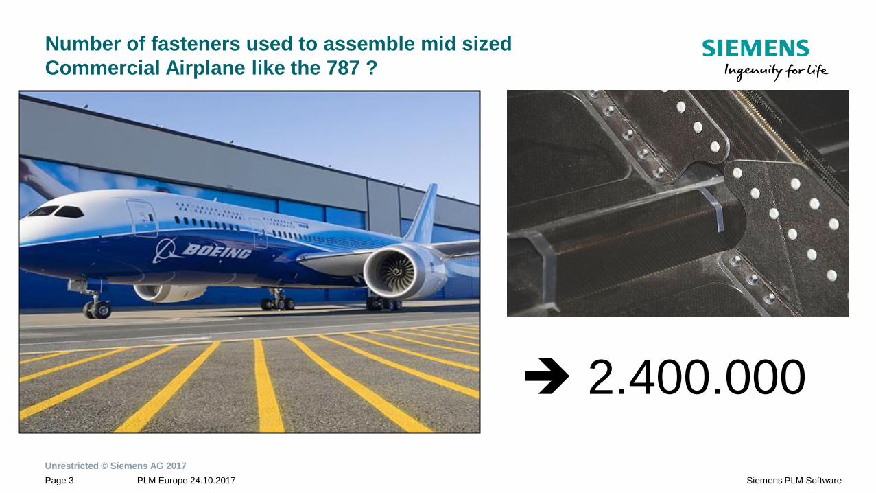
Number of fasteners used to assemble mid sized
Commercial Airplane like the 787 ?
2.400.000
Unrestricted © Siemens AG 2017
PLM Europe 24.10.2017Page 4 Siemens PLM Software
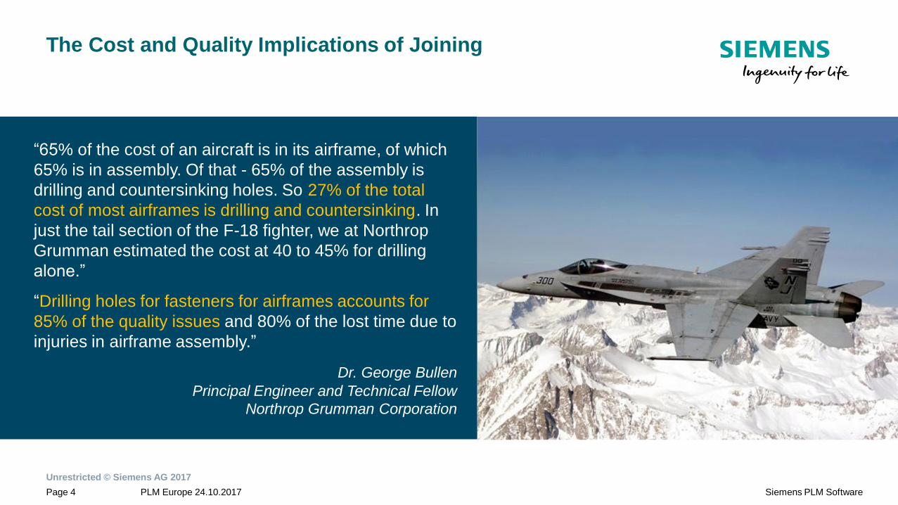
“65% of the cost of an aircraft is in its airframe, of which
65% is in assembly. Of that - 65% of the assembly is
drilling and countersinking holes. So 27% of the total
cost of most airframes is drilling and countersinking. In
just the tail section of the F-18 fighter, we at Northrop
Grumman estimated the cost at 40 to 45% for drilling
alone.”
“Drilling holes for fasteners for airframes accounts for
85% of the quality issues and 80% of the lost time due to
injuries in airframe assembly.”
Dr. George Bullen
Principal Engineer and Technical Fellow
Northrop Grumman Corporation
The Cost and Quality Implications of Joining
Unrestricted © Siemens AG 2017
PLM Europe 24.10.2017Page 5 Siemens PLM Software
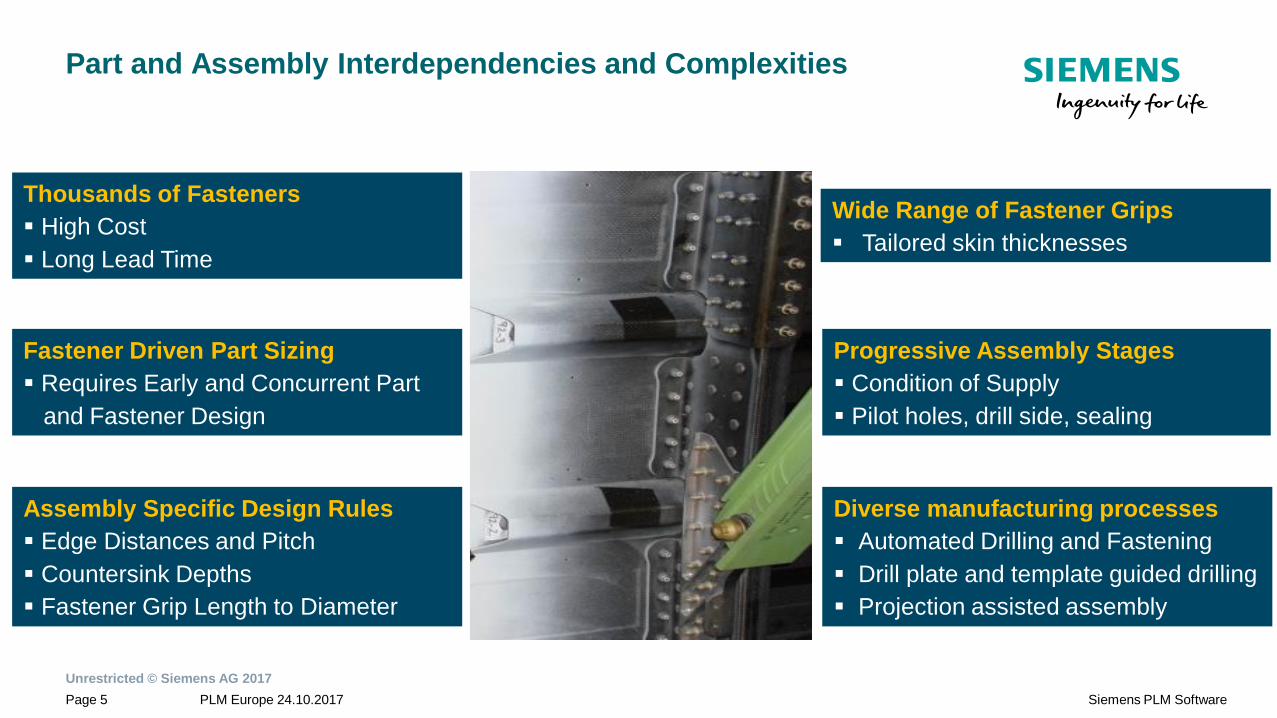
Progressive Assembly Stages
Condition of Supply
Pilot holes, drill side, sealing
Assembly Specific Design Rules
Edge Distances and Pitch
Countersink Depths
Fastener Grip Length to Diameter
Wide Range of Fastener Grips
Tailored skin thicknesses
Thousands of Fasteners
High Cost
Long Lead Time
Diverse manufacturing processes
Automated Drilling and Fastening
Drill plate and template guided drilling
Projection assisted assembly
Fastener Driven Part Sizing
Requires Early and Concurrent Part
and Fastener Design
Part and Assembly Interdependencies and Complexities
Unrestricted © Siemens AG 2017
PLM Europe 24.10.2017Page 6 Siemens PLM Software
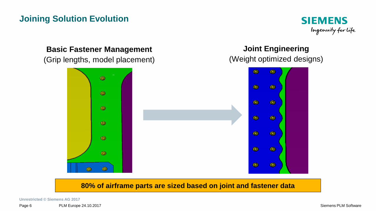
Joining Solution Evolution
80% of airframe parts are sized based on joint and fastener data
Basic Fastener Management
(Grip lengths, model placement)
Joint Engineering
(Weight optimized designs)
Unrestricted © Siemens AG 2017
PLM Europe 24.10.2017Page 7 Siemens PLM Software
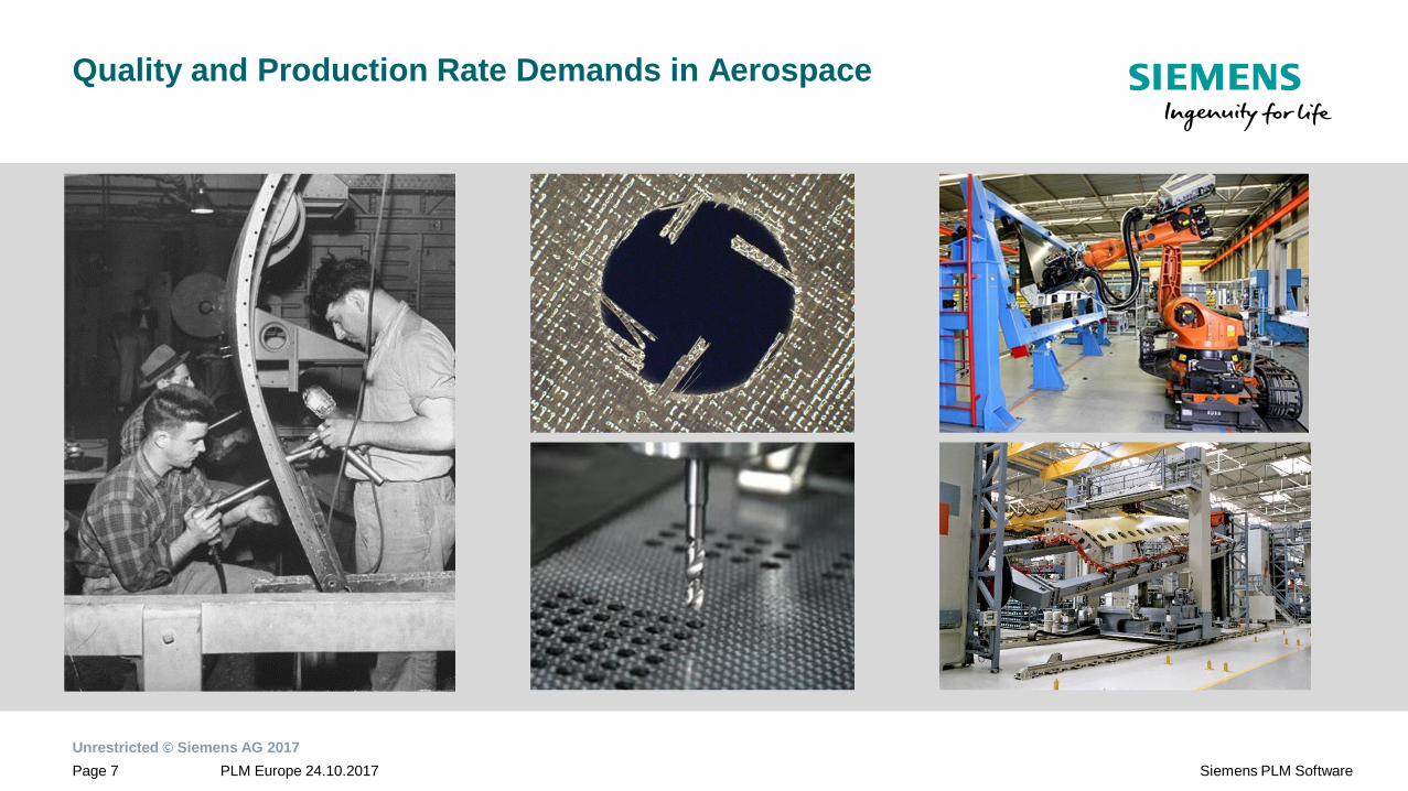
Quality and Production Rate Demands in Aerospace

Unrestricted © Siemens AG 2017
PLM Europe 24.10.2017Page 8 Siemens PLM Software
Define
Assembly
Joints
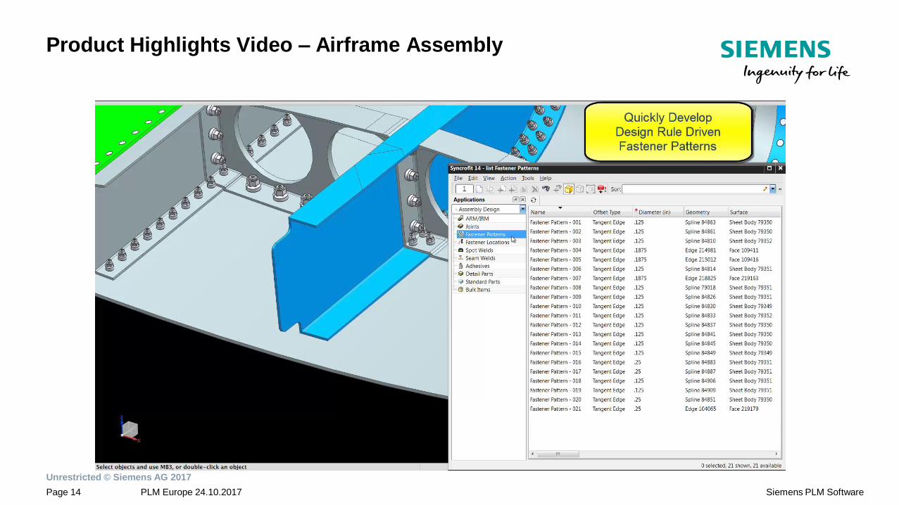
Develop Fastening Patterns
from design rules
Define Joining Details
(Fastening, Holes,
Sealing and
Installation)
Validate Design Rules
to avoid costly
changes
Automatically Position
and Visualize Fasteners
Leverage the digital
thread for Automated
Assembly Processes
Optimized
Assembly
The Path to a Fully Optimized Aerostructure with
SIEMENS SYNCROFIT

Unrestricted © Siemens AG 2017
PLM Europe 24.10.2017Page 9 Siemens PLM Software
CAD Integrated (NX and CATIA V5)
Intuitive UI with Common Joining Objects
Associativity to Geometry at Feature Level
Database Access of Standards
Efficient Authoring and Modification of
Joining Data within the Syncrofit Master Model
Unrestricted © Siemens AG 2017
PLM Europe 24.10.2017Page 10 Siemens PLM Software
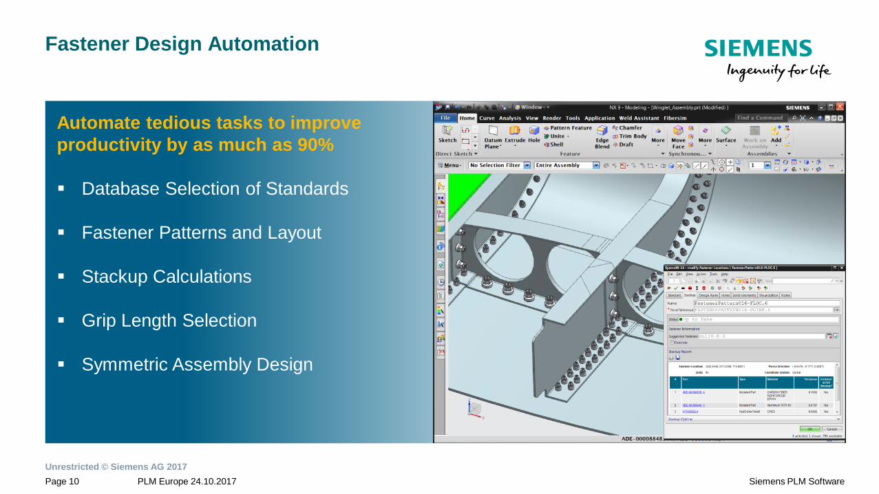
Fastener Design Automation
Automate tedious tasks to improve
productivity by as much as 90%
Database Selection of Standards
Fastener Patterns and Layout
Stackup Calculations
Grip Length Selection
Symmetric Assembly Design
Unrestricted © Siemens AG 2017
PLM Europe 24.10.2017Page 11 Siemens PLM Software
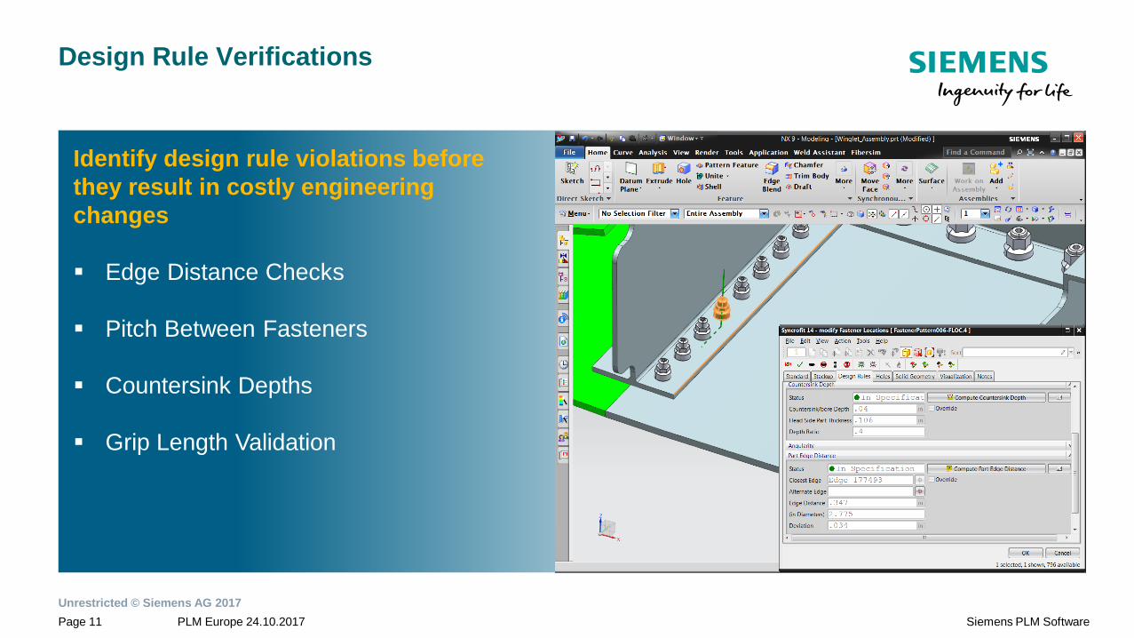
Design Rule Verifications
Identify design rule violations before
they result in costly engineering
changes
Edge Distance Checks
Pitch Between Fasteners
Countersink Depths
Grip Length Validation
Unrestricted © Siemens AG 2017
PLM Europe 24.10.2017Page 12 Siemens PLM Software
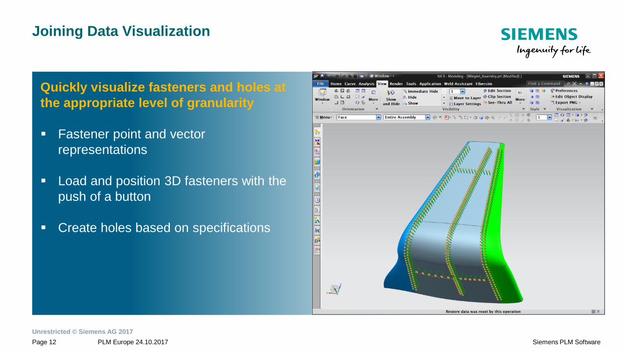
Joining Data Visualization
Quickly visualize fasteners and holes at
the appropriate level of granularity
Fastener point and vector
representations
Load and position 3D fasteners with the
push of a button
Create holes based on specifications
Unrestricted © Siemens AG 2017
PLM Europe 24.10.2017Page 13 Siemens PLM Software
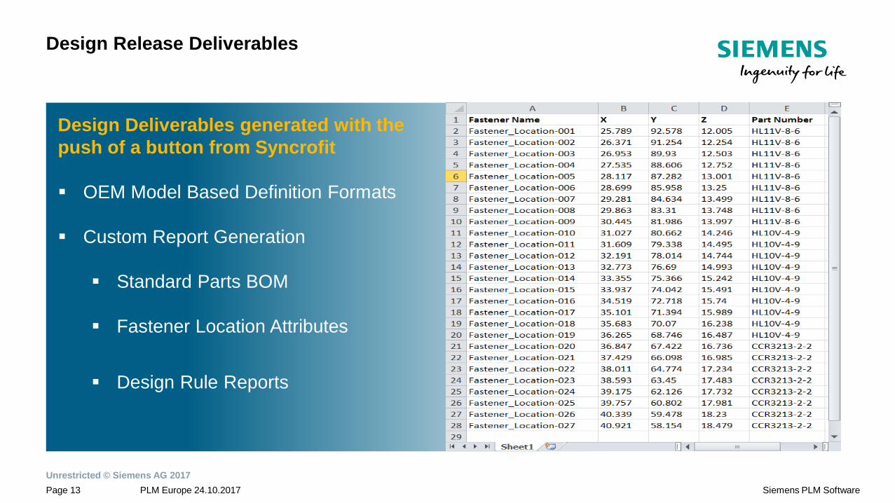
Design Release Deliverables
Design Deliverables generated with the
push of a button from Syncrofit
OEM Model Based Definition Formats
Custom Report Generation
Standard Parts BOM
Fastener Location Attributes
Design Rule Reports
Unrestricted © Siemens AG 2017
PLM Europe 24.10.2017Page 14 Siemens PLM Software
Product Highlights Video – Airframe Assembly

Unrestricted © Siemens AG 2017
PLM Europe 24.10.2017Page 15 Siemens PLM Software
Master model design with digital thread to support manufacturing processes
Early and continuously updated documentationand BOM to enable concurrent processes
Up to 90% reduction in design efforts forplacement of joining elements
Instantaneous feedback on design to reduce ECOs
Faster, earlier, and more accurate definitionbased on design standards
Joints Definitions(Bolts, Rivets, Welds, Adhesives)
Design Rule Verifications(Edge Distances, Pitch, Csink Depth…)
Assembly Visualization(Points, Vectors, Solids, Holes)
Engineering Release Data(Symmetry, MBD, BOM, Reporting)
Manufacturing Consumption(Assembly States, NC Programming Data)
Syncrofit Benefits Overview
Unrestricted © Siemens AG 2017
PLM Europe 24.10.2017Page 16 Siemens PLM Software
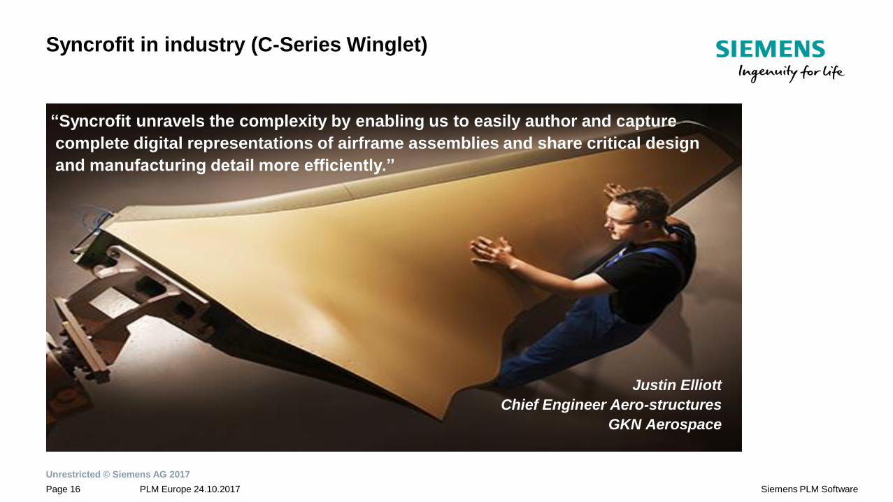
Syncrofit in industry (C-Series Winglet)
“Syncrofit unravels the complexity by enabling us to easily author and capture
complete digital representations of airframe assemblies and share critical design
and manufacturing detail more efficiently.”
Justin Elliott
Chief Engineer Aero-structures
GKN Aerospace
Unrestricted © Siemens AG 2017
PLM Europe 24.10.2017Page 17 Siemens PLM Software
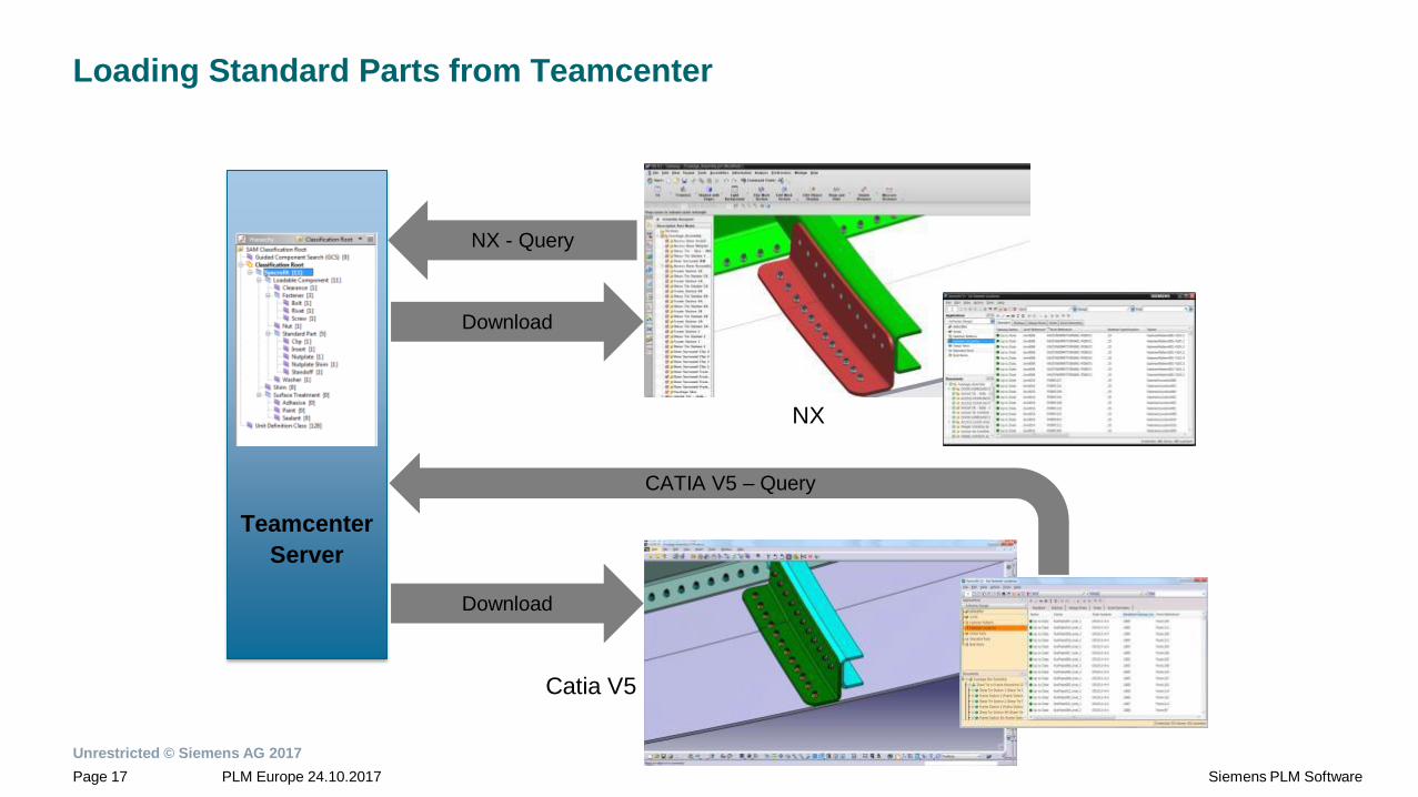
Loading Standard Parts from Teamcenter
Teamcenter
Server
Catia V5
Download
NX - Query
NX
CATIA V5 – Query
Download
Unrestricted © Siemens AG 2017
PLM Europe 24.10.2017Page 18 Siemens PLM Software
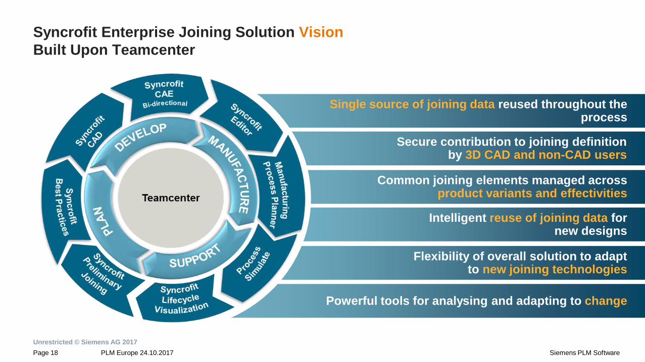
Single source of joining data reused throughout theprocess
Secure contribution to joining definitionby 3D CAD and non-CAD users
Common joining elements managed across product variants and effectivities
Intelligent reuse of joining data for new designs
Flexibility of overall solution to adapt to new joining technologies
Powerful tools for analysing and adapting to change
Syncrofit Enterprise Joining Solution Vision
Built Upon Teamcenter
Unrestricted © Siemens AG 2017
PLM Europe 24.10.2017Page 19 Siemens PLM Software
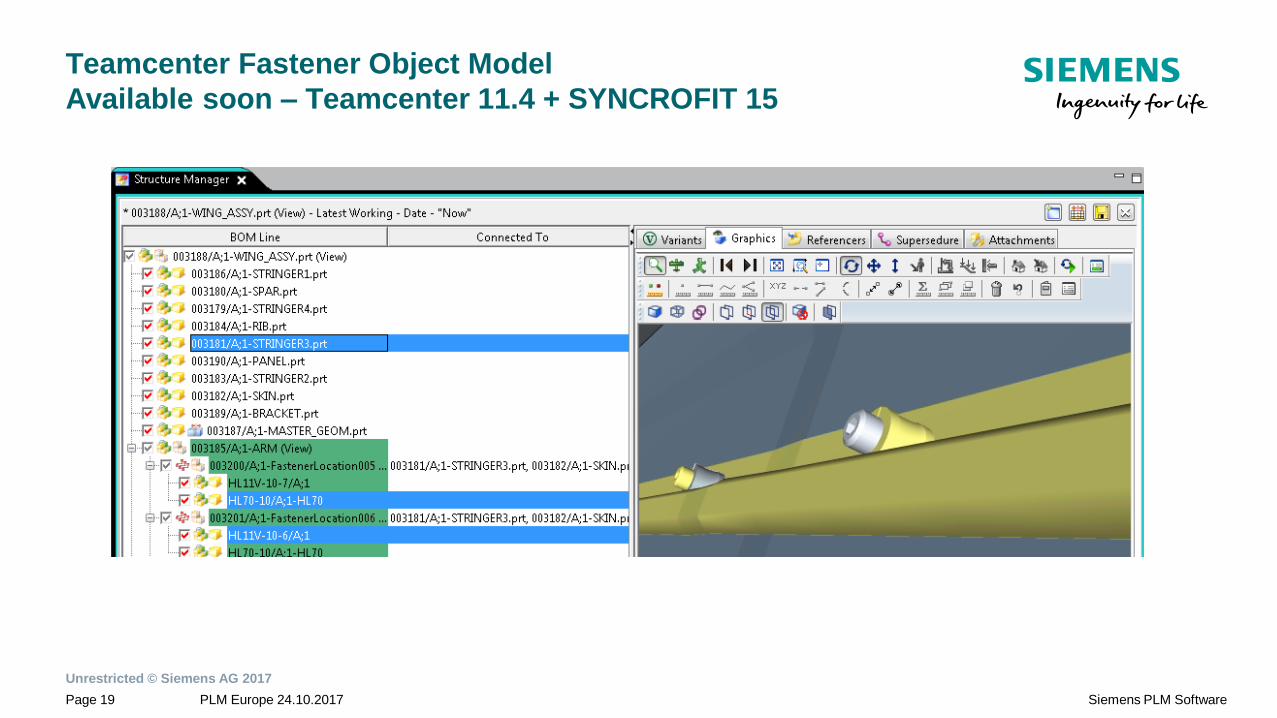
Teamcenter Fastener Object Model
Available soon – Teamcenter 11.4 + SYNCROFIT 15
Unrestricted © Siemens AG 2017
PLM Europe 24.10.2017Page 20 Siemens PLM Software
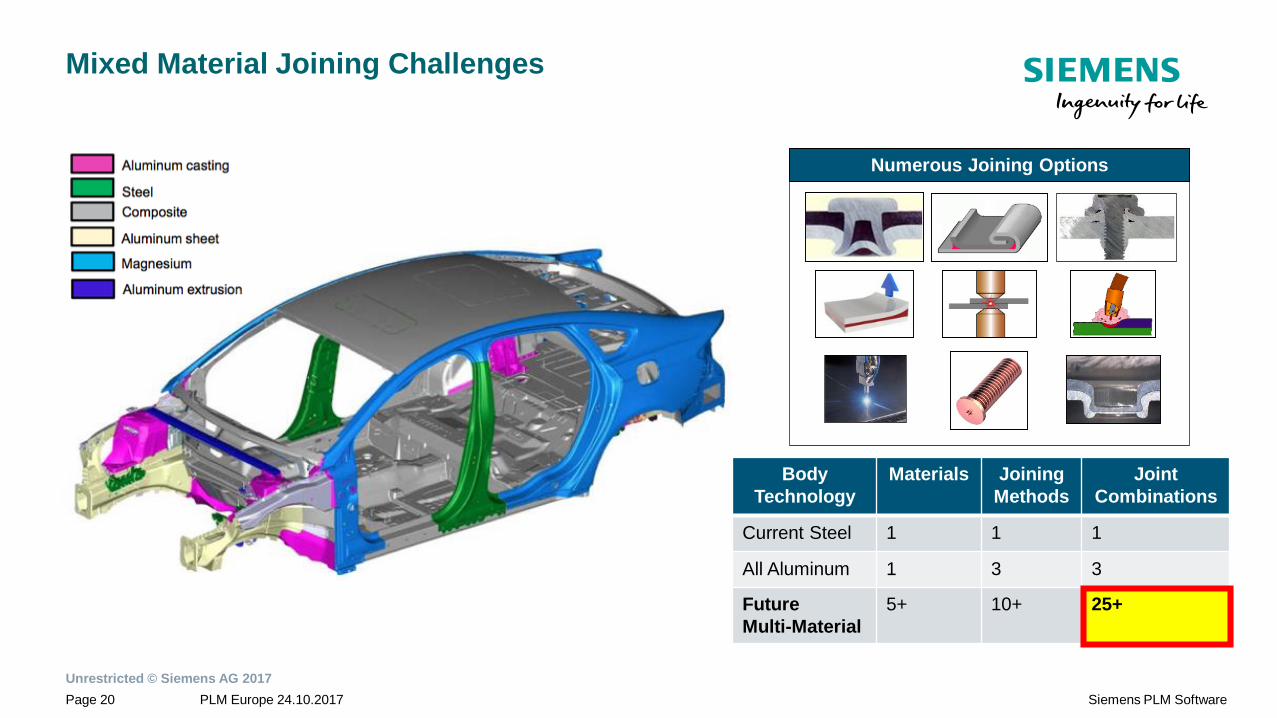
Mixed Material Joining Challenges
Body
Technology
Materials Joining
Methods
Joint
Combinations
Current Steel 1 1 1
All Aluminum 1 3 3
Future
Multi-Material
5+ 10+ 25+
Numerous Joining Options
Unrestricted © Siemens AG 2017
PLM Europe 24.10.2017Page 21 Siemens PLM Software
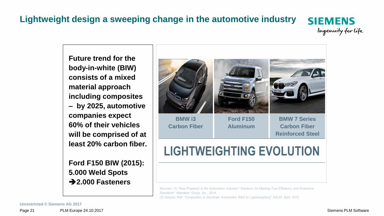
BMW i3
Carbon Fiber
BMW 7 Series
Carbon Fiber
Reinforced Steel
Ford F150
Aluminum
Lightweight design a sweeping change in the automotive industry
Future trend for the
body-in-white (BIW)
consists of a mixed
material approach
including composites
– by 2025, automotive
companies expect
60% of their vehicles
will be comprised of at
least 20% carbon fiber.
Ford F150 BIW (2015):
5.000 Weld Spots
2.000 FastenersSources: (1) “How Prepared Is the Automotive Industry? Solutions for Meeting Fuel Efficiency and Emissions
Standards” Aberdeen Group, Inc., 2014.
(2) Industry Poll: “Composites to Dominate Automotive R&D for Lightweighting” GALM, April, 2015.
LIGHTWEIGHTING EVOLUTION
Unrestricted © Siemens AG 2017
PLM Europe 24.10.2017Page 22 Siemens PLM Software
Boris Vetter
Senior Consultant
SIEMENS Industry Software GmbH & Co. KG
Digital Factory Division
Product Lifecycle Management
Global Sales & Services
Otto-Hahn-Ring 6
81739 München, Germany
Mobile: +49 (174) 7341 606
THANK YOU !
www.siemens.com/PLM