Embed Size (px)
Citation preview
Copyright © Siemens AG, 2014. All rights reserved.
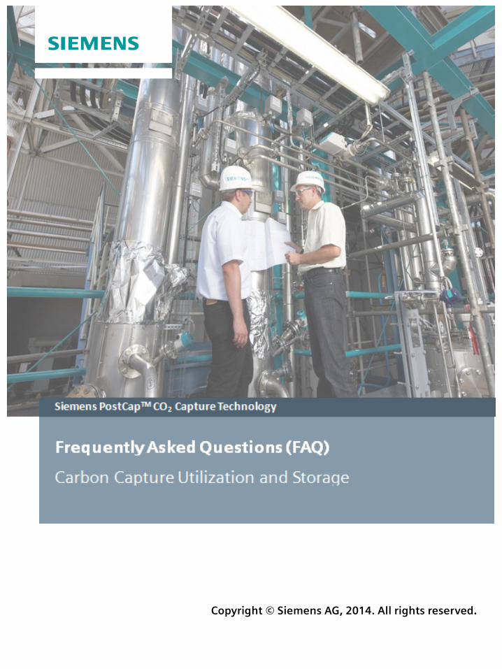
Siemens PostCapTM CO2 Capture Technology
Siemens AG CCUS - Frequently asked questions (FAQs)
Contents
1. Carbon Capture Utilization and Storage (CCUS) ......................................................... 5
1.1 What is CO2? ..................................................................................................................... 5
1.2 How much CO2 happens in the atmosphere? ................................................................... 5
1.3 Why the need for CCUS? .................................................................................................. 5
1.4 What is behind the CCUS technology? ............................................................................. 5
1.5 What is carbon capture? ................................................................................................... 6
1.6 What happens with the captured CO2? ............................................................................. 6
1.7 How does the CCUS method work and of which steps does the CCUS-method consist? 6
1.8 Does no more CO2 at all escape into the atmosphere with CCUS? .................................. 6
1.9 Which method does Siemens apply in the range of CCUS? ............................................. 6
2. CO2 separation by means of post-combustion technology ........................................ 7
2.1 What distinguishes the post-combustion method in comparison with other CCUS technologies? .................................................................................................................... 7
2.2 How does the post-combustion method work? ................................................................. 7
2.3 Does Siemens offer a proprietary post-combustion method? ........................................... 7
2.4 What are the advantages of the Siemens PostCapTM process? ........................................ 7
2.5 How high is the energy consumption of the capture process? .......................................... 8
2.6 What are the experiences concerning Siemens PostCapTM process? .............................. 8
2.7 Have post-combustion plants already been built for large-scale power stations? ............. 8
3. Solvents for Post-Combustion ....................................................................................... 9
3.1 Which solvents are used for CCUS? ................................................................................. 9
3.2 What are amines? ............................................................................................................. 9
3.3 What are amino acids in detail? ........................................................................................ 9
3.4 Which solvent is used for the Siemens PostCapTM process? What is special about it? .... 9
3.5 Is the solvent used for the Siemens PostCapTM process harmful? .................................. 10
3.6 What are the advantages of the new process compared to the classic MEA absorption process? .......................................................................................................................... 10
3.7 How can potential solvent emissions be avoided? .......................................................... 10
Copyright © Siemens AG, 2014. Page 2 of 23 All rights reserved.
Siemens AG CCUS - Frequently asked questions (FAQs)
3.8 What is the specific heat required for regeneration? ....................................................... 10
3.9 Which pollutant levels in the flue gas (such as SOx) can be tolerated by the solvent? ... 10
4. Siemens PostCapTM pilot plant Staudinger ................................................................. 11
4.1 What is the pilot plant Staudinger? .................................................................................. 11
4.2 How does the pilot plant work? ....................................................................................... 11
4.3 How can it be assured that the results can be transferred to large-scale plants? ........... 11
4.4 Can solvent be released from the pilot plant into the environment? ............................... 11
4.5 How pure is the solvent used in the pilot plant? .............................................................. 11
4.6 What experience has already been gathered with the solvent before it has been used in Staudinger? ..................................................................................................................... 12
4.7 Who is financing the operation of the pilot plant? ............................................................ 12
4.8 What happens with the CO2 from the pilot plant? ............................................................ 12
4.9 How long is the pilot plant already in operation? ............................................................. 12
4.10 What is the performance of the pilot plant? How much CO2 is captured? ....................... 12
5. Climate policy, emission trading and NER300 ........................................................... 13
5.1 Is CCUS mandatory? ...................................................................................................... 13
5.2 How does emissions trading work? ................................................................................ 13
5.3 How much certificates are traded in Germany? .............................................................. 13
5.4 What is meant by „backloading“? .................................................................................... 14
5.5 What is the NER300 program? ....................................................................................... 14
5.6 How many certificates were sold, how much € were earned with the sold certificates? . 14
5.7 How many projects are supported in the context of NER300? ........................................ 15
5.8 How many power stations shall be equipped with CCUS worldwide?............................. 15
6. Economic efficiency ...................................................................................................... 16
6.1 What are the advantages of the new process compared to the classic MEA absorption process? .......................................................................................................................... 16
6.2 How much is the separation and storage of CO2? .......................................................... 16
6.3 Who takes on the costs? ................................................................................................. 16
Copyright © Siemens AG, 2014. Page 3 of 23 All rights reserved.
Siemens AG CCUS - Frequently asked questions (FAQs)
7. Transport ....................................................................................................................... 17
7.1 How will carbon dioxide (CO2) be transported? ............................................................... 17
7.2 Is transport of carbon dioxide safe? ................................................................................ 17
7.3 What Health and Safety standards exist for the transport of carbon dioxide? ................ 17
7.4 What length will pipelines be? ......................................................................................... 18
7.5 What does a pipeline look like? ....................................................................................... 18
8. Storage .......................................................................................................................... 19
8.1 Where are storage capacities? ........................................................................................ 19
8.2 How safe is the underground storage of CO2? ................................................................ 19
8.3 What are the geological criteria for a safe storage site? ................................................. 20
8.4 Which mechanism hold the CO2 tight in the depth? ........................................................ 20
8.5 What impact does CO2 have on groundwater and rock matrix? ...................................... 20
8.6 How can the storage sites be monitored? ....................................................................... 21
8.7 What happens if CO2 does escape the storage site? ...................................................... 21
8.8 Can CO2 storage cause earthquakes? ............................................................................ 22
8.9 Has the CCS technology been sufficiently tested? ......................................................... 22
8.10 What challenges remain to be solved? ........................................................................... 22
9. (Definitions and) abbreviations .................................................................................... 23
Copyright © Siemens AG, 2014. Page 4 of 23 All rights reserved.
Siemens AG CCUS - Frequently asked questions (FAQs)
1. Carbon Capture Utilization and Storage (CCUS)
1.1 What is CO2? CO2 is a chemical compound of carbon and oxygen. It is colorless and odorless, not explosively, incombustible and non-toxic. It is heavier than air and can displace oxygen in confined areas. CO2 is gaseous in the ambient air, thus at an atmospheric pressure of 1 bar and 20°C. Thereby CO2 is heavier than air approximately 1.5 times. At very low temperatures CO2 is existent in solid state, so-called dry ice. At the warming of dry ice up to ambient temperature the liquid state of aggregation is skipped (one speaks about sublimitation) and the CO2 becomes directly gaseous. It can be transported in the liquid state (tanker, whereby it has to be cooled) or in supercritical state via pipelines. The critical point is at 74 bar and 31°C.
CO2 is always available around us. We breathe it in and it is a vigorous component for the life and growth of plants. CO2 is in industrial use already for many decades; in food manufacturing including lemonades, in fire extinguishers, etc.
1.2 How much CO2 happens in the atmosphere? CO2 is available in traces in the atmosphere, which is supposed to have a considerable impact on the climate. Currently the global average CO2 content amounts to 398 ppm (February 2014). The definition of ppm is: The relationship of CO2 molecules in a volume unity of air to the number of all molecules in the same volume apart from the water molecules. 398 ppm corresponds to a relationship of 0,000398. The majority of climate experts are of the opinion that a global warming of the earth`s atmosphere on average by 2°C compared to the temperature level before the beginning of the industrial age can only be avoided, if the CO2 concentration remains below 450 ppm. The annual increase of the CO2 concentration seems to accelerate and is at 2.4 ppm/a. 1
1.3 Why the need for CCUS? The 2-degree-target leads to the necessity to reduce the CO2 emissions in the energy sector by 50% until 2050 (in comparison with 2009). Internationally, China, India, Brazil, South Africa and Mexico will drive a major global energy demand increase, which is likely to be met in large part from fossil fuels. Energy efficiency and renewable energy sources are on a long-term basis the most sustainable solutions in regard to security of supply and climate protection but in the general opinion the 2 degree target cannot be achieved without the capture and storage of CO2.
1.4 What is behind the CCUS technology? The Carbon Capture Utilization and Storage technology – short CCUS – enables a low CO2 generation of electricity from fossil sources of energy (e.g. coal and gas). By capturing the CO2 created through burning fossil resources and storing it underground only a fraction of the otherwise usual CO2 emissions reaches the atmosphere. The aim is to reduce the greenhouse effect (climate warming) caused by CO2 in the atmosphere.
1 Earth System Research Laboratory, Global Monitoring Division, NOAA, April 2014 Copyright © Siemens AG, 2014. Page 5 of 23 All rights reserved.
Siemens AG CCUS - Frequently asked questions (FAQs)
1.5 What is carbon capture? Carbon capture is a technical process, which involves removing carbon dioxide (CO2) from the gases discarded by industry. The major target of carbon capture is to reduce CO2 emissions from power generation from fossil fuels, mainly coal and natural gas. But carbon capture can also be applied to CO2-intensive industries such as cement, refineries, iron and steel, petrochemicals, oil and gas processing and others.
1.6 What happens with the captured CO2? Following the capture of CO2 it is transported to a suitable geological formation in which it is stored, to keep it away long-term from the atmosphere. Either depleted oil and gas deposits or deep saltwater containing geological sedimentation deposits serve as storage formations. Besides the storage, however, the CO2 can also further be used industrially, e.g. in the food-/ beverage industry and in the oil and gas industry for the improvement of oil and gas exploration from aging oil/gas fields (Enhanced Oil Recovery “EOR”).
1.7 How does the CCUS method work and of which steps does the CCUS-method consist?
The CCUS method consists of three steps: the separation or capture, the transport and the use/storage of CO2. There are currently available three different mature processes for the CO2 capture:
a) the separation of CO2 from of the waste gas from conventional combustion processes, i.e. capturing after burning (so-called “post-combustion“ method),
b) the separation of CO2 from a gas mixture (synthesis gas generated by means of coal gasification) before burning (so-called “pre-Combustion” method) and
c) the separation by means of condensation of the waste gas from combustion processes driven by pure oxygen instead of ambient air (so-called “Oxyfuel” method).
Information about transport, storage and utilization are found in the further course of this document.
1.8 Does no more CO2 at all escape into the atmosphere with CCUS? In comparison with electricity generation in conventional power stations only around 10 – 15 % of the amounts of CO2 are given to the atmosphere in power stations with CCUS technology. 85 – 90 % of the CO2 can be captured with CO2-separation.
1.9 Which method does Siemens apply in the range of CCUS? Siemens favors the downstream separation of CO2 (“post-combustion capture“). An own method (so-called Siemens PostCapTM) is applicable for new construction and retrofitting of large-scale fossil fired power stations.
Copyright © Siemens AG, 2014. Page 6 of 23 All rights reserved.
Siemens AG CCUS - Frequently asked questions (FAQs)
2. CO2 separation by means of post-combustion technology
2.1 What distinguishes the post-combustion method in comparison with other CCUS technologies?
Post-Combustion, compared with Pre-Combustion and Oxyfuel, has the advantage that besides new built projects existing power stations with sufficient space can be retrofitted with CO2 separation as well. In addition, the post-combustion method can be implemented very flexibly in a variety of scales, e.g. if only a slip stream of the waste gas should be treated.
2.2 How does the post-combustion method work? The post-combustion method is based on the principle of absorption-desorption by means of special chemical solvent. The flue gas of the power station is vented into a column (the absorber) in which the solvent is sprayed. The solvent combines with CO2 and separates it from the remaining flue gas. The cleaned flue gas escapes into the atmosphere at the top of the absorber whereas the loaded solvent with CO2 is collected at the bottom of the absorber. From there it is pumped to another column (the desorber). The separation of solvent and CO2 is carried out in the desorber through heating the rich solvent. The pure CO2 escapes at the head of the desorber and is compressed for further use or storage. The solvent at the bottom of the desorber is pumped back into the absorber to wash CO2 again out of the flue gas. Siemens has developed an own post-combustion method based on a special solvent: The Siemens PostCapTM process.
2.3 Does Siemens offer a proprietary post-combustion method? Siemens has developed an own post-combustion method based on a special solvent: The Siemens PostCapTM process. It was developed over several years and its functionality has been validated in a pilot plant successfully since 2009. The process was further developed in detail while executing several studies. On basis of these results Siemens offers the PostCapTM process for demonstration projects. The scope of a license package comprises the following elements: process design and engineering services, support of construction and commissioning as well as the license for the construction and operation of the plant. Furthermore Siemens provides a key component of the CO2 capture plant, the „reclaimer“ as proprietary equipment.
2.4 What are the advantages of the Siemens PostCapTM process? The special strengths of the Siemens PostCapTM method are: hardly detectable emissions of the solvent, good solvent stability against reduction mechanism – in particular against oxygen (and thereby a low solvent consumption), environmentally friendly and simply manageable solvent for power plant operators and staff. Low energy consumption, high capture rates of CO2 and CO2 purity are comparable to or better than those of other suppliers.
Copyright © Siemens AG, 2014. Page 7 of 23 All rights reserved.
Siemens AG CCUS - Frequently asked questions (FAQs)
2.5 How high is the energy consumption of the capture process? Of course energy is also needed for the capture process. The net loss of energy for the separation of CO2 with PostCap from a large scale power station amounts to about 6 percent points loss of net efficiency without consideration of compressor power for CO2-transport. The aim is to minimize this loss further.
2.6 What are the experiences concerning Siemens PostCapTM process? Siemens combines the know-how in the design and building of power station components up to turnkey power stations with the knowledge of chemical process development and process design. Based on this expertise Siemens developed the PostCapTM CO2 capturing process which optimally takes into consideration the needs of power stations. Furthermore it has the potential to be used in other industrial processes. In addition to the operation of the pilot plant (details see below) Siemens has already carried out several engineering studies for large-scale projects. Siemens could successfully complete the technology qualification program for the large scale CCUS project at the refinery Mongstad in Norway. The one and a half year technology qualification program comprised solvent stress tests, a pilot plant operation and a comprehensive engineering of the large-scale CO2 capture plant. Further FEED (Front End Engineering Design) studies were carried out in the context of earlier projects among others for a large-scale CO2 separating plant at a natural gas power station in Abu Dhabi on behalf of the customer Masdar with whom there has also been a development partnership in place since 2011.
2.7 Have post-combustion plants already been built for large-scale power stations?
Worldwide a small number of pilot plants were already built by different suppliers in order to test the post-combustion method. The largest of them deliver approx. 100.000 t/a to 150.000 t/a CO2. Also Siemens has built a pilot plant at the E.ON’s power station Staudinger in cooperation with E.ON, which has been in operation since 2009 (details see below). At present there is no commercial -scale CO2 capture plant (150,000 t/a to 1,000,000 t/a CO2) in operation yet. Construction of one large capture plant located in Canada owned by the utility SaskPower has been completed (April 2014). There approx. 1,000,000 t/a CO2 should be used for tertiary oil production (EOR). In addition, globally some other large-scale projects are in the planning stage, but the realization depends on the economics and the necessary financial support.
Copyright © Siemens AG, 2014. Page 8 of 23 All rights reserved.
Siemens AG CCUS - Frequently asked questions (FAQs)
3. Solvents for Post-Combustion
3.1 Which solvents are used for CCUS? Basically aqueous solutions of ammonia, amines and amino acid salts are used for CCUS, because as alkaline solvents they are able to selectively bind acetic gases such as CO2, and release them at elevated temperatures. This way CO2 (usually around 90 %) can be specifically removed from flue gases after combustion (as well as from industrial waste gases). The rest of the gas stream is not absorbed by the solvent and leaves the absorber on top as cleaned flue gas, consisting mainly of nitrogen, oxygen, water vapor and the remaining CO2. These are also the key components of ambient air. The mechanism of binding the CO2 in the solvent is called chemical absorption. The release of CO2 from the solvent, which leads to the production of nearly pure CO2 is called desorption and is realized by means of thermal energy. Trace components in the flue gas, such as SOx and NOx as well as parts of the oxygen, have the tendency to get absorbed in the solvent, too, or to change it chemically. These are some of the peculiarities and challenges with respect to different solvents.
3.2 What are amines? Amines are derivatives of ammonia. All amines form alkaline aqueous solutions and can absorb acetic gases, such as CO2, by means of covalent bonding. Amines are ingredients of e.g. fertilizers, cosmetic products and detergents.
3.3 What are amino acids in detail? Amino acids are organic derivatives of ammonia (NH3). They are essential parts of proteins and thus basic modules of life. Proteins which are valuable for human organisms are for instance contained in meat. There are many different amino acids. Taurine, for example, is also an amino acid, and is contained in energy drinks because of its stimulating effect. Other amino acids are applied as additives to food and animal feed. In the medical field amino acids are used for the production of nutrient solutions (infusions). Nowadays, amino acids are industrially produced in large scale.
3.4 Which solvent is used for the Siemens PostCapTM process? What is special about it?
A chemical solvent is applied because of its high selectivity towards CO2 and high absorption capacity. It is the salt of an amino acid (amino acid salt) in aqueous solution, called an amino acid salt solution. Like all salts it features a very low vapor pressure, i.e. in the PostCapTM process practically no solvent vapor is emitted to the environment. This is a decisive difference compared to processes based on amines. Furthermore it has a high selectivity, i.e. particularly pure CO2 is gained. The amino acid salt decomposes only in smallest quantities during regeneration. Due to the good absorption properties only a comparably small amount of solvent is necessary, resulting in economic advantages. In addition, amino acid salts are biodegradable.
Copyright © Siemens AG, 2014. Page 9 of 23 All rights reserved.
Siemens AG CCUS - Frequently asked questions (FAQs)
3.5 Is the solvent used for the Siemens PostCapTM process harmful? The solvent is biodegradable, which means that the solvent is disintegrated in the soil by bacteria (in case it ends up in the soil, which of course is prevented by technical measures). Since it is not evaporated, there is no danger of ignition, explosion or inhalation. If ingested, the amino acid salt used by Siemens for CO2 scrubbing is less harmful than common table salt (NaCl), which is contained in food products. The liquid solvent behaves like a lye, meaning that it is slightly alkaline (pH > 7) and causes skin irritation – like other cleaning solvents, too. Concerning occupational health & safety, handling of these substances demands the use of appropriate standard personal protective equipment such as goggles.
3.6 What are the advantages of the new process compared to the classic MEA absorption process?
Less energy is required for solvent regeneration. The solvent is more stable, and the process can be optimally integrated into the power plant.
3.7 How can potential solvent emissions be avoided? It is important that as little solvent as possible is carried into the environment with the treated flue gas released on top of the absorber. Due to the salt character of the solvent used by Siemens there is no evaporation. To prevent solvent entrainment, a standard droplet separator is sufficient. In the Siemens PostCapTM process, there is no need for an additional washing step on top of the absorber. Furthermore, the solvent features favorable environmental properties.
3.8 What is the specific heat required for regeneration? The specific heat required for desorption of the CO2 depends both on the characteristics of the solvent as well as on process parameters and is thus subject to complex relationships. At present, the specific heat required in the PostCapTM process amounts to approx. 2.7 GJ per ton of CO2 separated. Reduction of this figure is one of the goals of further development work within Siemens.
3.9 Which pollutant levels in the flue gas (such as SOx) can be tolerated by the solvent?
Some trace components contained in the flue gas, such as SOx and NOx, are also absorbed and thus lead to pollution of the solvent. Oxygen also results in negative effects on the solvent, however the amino acid salt is much more resistant towards O2 than conventional amines. With respect to the SOx Siemens has developed a special method (so-called reclaimer) for cleaning / recycling. The solvent which is blocked by the sulphur is completely retrieved, and a sulphur containing product is gained, which can be sold to the fertilizer industry. Therefore higher SOx levels in the flue gas are basically tolerable for the PostCapTM process. However, an SOx removal upstream should be considered for economic reasons. Only NO2 (not NO) leads to a non-reversible degradation of the solvent. The NO2 degradation products are separated in a second process step of the reclaimer.
Copyright © Siemens AG, 2014. Page 10 of 23 All rights reserved.
Siemens AG CCUS - Frequently asked questions (FAQs)
4. Siemens PostCapTM pilot plant Staudinger
4.1 What is the pilot plant Staudinger? The pilot plant Staudinger is a “small scale” CO2 capture plant based on the Siemens PostCapTM process. The pilot plant is located at the E.ON coal-fired power plant Staudinger near Frankfurt, Germany. The pilot plant is used for testing, validation and optimization of the PostCapTM process under real flue gas conditions. The pilot plant is designed in such a way that the results from pilot plant operation can be transferred to large-scale units. Thus Siemens is able to design large scale CO2 capture plants.
4.2 How does the pilot plant work? The pilot plant works similar to large scale CO2 capture plants: A chemical washing process based on the principle of absorption-desorption is applied in which a special washing agent (=solvent) is used to absorb CO2 from flue gas. In a second step the CO2-rich solvent is heated up and CO2 is released (=desorption). It is a reversible process in which the solvent is continuously recirculated. The pilot plant is completely automated and can be operated via remote control.
4.3 How can it be assured that the results can be transferred to large-scale plants?
Siemens has long-time experience in chemical industry and in the scale-up of chemical processes. The pilot plant has the same effective separation height as large scale plants, whereas the diameter is as small as possible, but big enough to avoid scale-up issues caused by fringe effects.
4.4 Can solvent be released from the pilot plant into the environment? Solvent emissions into the atmosphere are effectively prevented by high-efficiency droplet separators. If a leakage would occur during pilot plant operation, a collecting tray will prevent solvent from seeping into the soil or groundwater. Due to the fact that the solvent used in Siemens PostCapTM process does not evaporate there is no risk that it can be released into the environment.
4.5 How pure is the solvent used in the pilot plant? The solvent used in the pilot plant is a fine chemical product of almost 100% purity. Less than 5 thousands are commonly ingredients that stem from the water used for production of the solvent. These ingredients may considerably affect color and smell but not the biological and chemical properties of the solvent.
Copyright © Siemens AG, 2014. Page 11 of 23 All rights reserved.
Siemens AG CCUS - Frequently asked questions (FAQs)
4.6 What experience has already been gathered with the solvent before it has been used in Staudinger?
Siemens is operating a laboratory plant at the Hoechst Industrial Park in Frankfurt, Germany where solvent properties for CO2-absorption can be investigated. The lab plant represents the complete absorption-desorption process and it is characterized by its capability to operate continuously and at a wide range of operating conditions. Before Siemens has decided in favor of the amino acid salt as solvent, many different solvents were tested in the automated lab plant. Afterwards several thousands of hours trial operation have been conducted.
4.7 Who is financing the operation of the pilot plant? Financial sources are Federal Ministry for Economic Affairs and Energy of Germany, Siemens and E.ON.
4.8 What happens with the CO2 from the pilot plant? The captured CO2 will be fed back into the overall flue gas flow of the coal-fired power plant. Pilot plant operation aimed at testing and validating the PostCapTM technology under real flue gas conditions. Geological storage of CO2 is not part of the project. Therefore captured CO2 is released back again into atmosphere.
4.9 How long is the pilot plant already in operation? Pilot plant operation has started in September 2009 and was operated for more than 9000 hours now. Within the framework of the Carbon Capture Mongstad (CCM) project (Norway) the pilot plant was equipped with a gas boiler in order to investigate the behavior for flue gas from gas fired power stations.
4.10 What is the performance of the pilot plant? How much CO2 is captured? The performance of the pilot plant is < 1 MWeq. Approximately 1.000 kilograms of CO2 are captured per day.
Copyright © Siemens AG, 2014. Page 12 of 23 All rights reserved.
Siemens AG CCUS - Frequently asked questions (FAQs)
5. Climate policy, emission trading and NER300
5.1 Is CCUS mandatory? For the time being, this cannot be expected. Indirect measures are preferred to incentivize the emitter to implement reduction strategies. These are among other emission standards and emission certificate trading systems. Europe has decided to a „Cap and trade“ system at which corresponding certificates must be bought by the emitters (at the moment only larger power stations) for any ton of CO2, which is produced. The total number of the certificates is reduced every year and the certificates can be traded themselves.
5.2 How does emissions trading work? 2 Emissions trading is a market-based system to reduce the emission of climate-damaging i.e. carbon dioxide (CO2). It is based on the principle of „Cap and Trade“: The cap makes sure that CO2 becomes a commodity and, thus, CO2 is valued at a price, which is determined by supply and demand at the (trading) market.
Initially, a cap is defined for the maximum emission value of CO2. This cap is calculated to be scarce. To the companies, which have to be part of emissions trading according to the legislation, a defined number of emission allowances (from the cap) is allocated. The allocation rules are defined Europe-wide. One emission allowance equals one ton of CO2. By limiting the available number of emission allowances (cap), concrete reduction targets are set for the companies. The allowances are tradeable and therefore serve as permits. Through the conversion of CO2 in tradeable permits, the ton of CO2 obtains a concrete value determined by the (trading) market.
Once a year, the companies have to surrender emission allowances according to their actual emissions. If a company reduces its emissions so that it has more allowances than it needs, it can sell the remaining (not needed) allowances at the market. The other way around it has to purchase additional allowances to comply with its surrender obligation. If a company does not fulfil its obligations to surrender allowances respectively reduce its emissions, it will be heavily fined. In the second trading period (2008-2010), the fine was 100 Euros per ton of emissions. In the third trading period, the amount of those sanctions adjusts to the increase of consumer prices. In addition, the obligation has to be fulfilled additionally in the following year.
It is also possible that a company buys additional allowances on the market, if emission reduction is deemed more expensive. This means that reduction measurements are conducted where they are most economic. By emissions trading and the so-called Cap-and-Trade-Principle climate protection can be both: ecological effective and economical efficient.
5.3 How much certificates are traded in Germany? The set to be auctioned by Germany of emission rights of the third trade period in the year 2013 amounts to 182.560.500 pieces.
2 German Emissions Trading Authority (DEHSt) at the Federal Environment Agency, April 2014 Copyright © Siemens AG, 2014. Page 13 of 23 All rights reserved.
Siemens AG CCUS - Frequently asked questions (FAQs)
5.4 What is meant by „backloading“? Backloading means the temporal moving of auction sets of the emission rights (EUA). The changed EU action ordinance has come into effect on February 27th, 2014. Europe-wide you shall auction overall 900 million emission rights less in the time period from 2014 to 2016 than you have provided till now. At first the amounts of auction are reduced around 400 million EUA in 2014. Then the cut amounts to 300 million and 2016 to 200 million EUA. By the cut amounts of auction 300 million EUA are led back in 2019 and 600 million in 2020. Germany bears a share of round 19,35 per cent of the total cut amount. The German amount of auction in the current year 2014 reduces correspondingly from now 204.534.500 on 127.127.500 EUA.
5.5 What is the NER300 program? On November 3rd, 2010 the EU commission made the decision on the auction of 300 million CO2 emission certificates taken hold of „New Entrants‘ Reserve“ of the European Emissions Trading Scheme for the purpose to support CCUS and renewable energy demonstration projects in their EU member states. The auction proceeds support propositions which either target environmental friendly separation and geological storage of CO2 (“CCUS demonstration projects”) or target innovative technologies for renewable energies (RES demonstration projects”).
5.6 How many certificates were sold, how much € were earned with the sold certificates?3
The European Commission (EC) appointed the EIB as an agent for the implementation of the NER300 Initiative, which has the goal to raise financing for carbon capture and storage (CCS) and innovative renewable energy (RES) projects through the sale of EUAs from the New Entrant Reserve of the European Emissions Trading Scheme.
As part of this initiative, the EIB is selling 300 million EUAs divided into a first tranche of 200 million EUAs, and a second tranche of 100 million EUAs. The monetization was divided into two phases.
The EIB sold a total volume of 200 million EUAs for a total value of EUR 1,609,125,460 (before deduction of expenses and fees). Sales were evenly distributed over the ten month period in order to maximize market liquidity and minimize any adverse market impacts.
The EIB sold 200 million EU Allowances between 5 December 2011 and 28 September 2012 at an average price of EUR 8.05 per EU Allowance.
3 European Investment Bank, April 2014 Copyright © Siemens AG, 2014. Page 14 of 23 All rights reserved.
Siemens AG CCUS - Frequently asked questions (FAQs)
5.7 How many projects are supported in the context of NER300? In the context of the first round of the NER300 initiative the EIB has successfully checked with standard banking practice care within 9 month 79 projects and supported and advised continuously the European Commission at her financial decisions for NER300 projects. 23 projects received a promoting acceptance, however no CCUS projects were part of the supported plans. This can be explained by that the project sponsors or the member states pulled back their support of the submitted CCUS project suggestions in the course of the bidding procedure.
The European Commission published the second request for the submission of project suggestion in April 2013. In July 2013, 33 project applications entered the EIB, which were carefully checked. The European Commission will announce its financial aid decisions in the second term of 2014. One CCUS project is resided under the suggestions.
5.8 How many power stations shall be equipped with CCUS worldwide? The worldwide CO2 avoidance potential by CCUS until 2100 is valued by the IPCC at 220 to 2.220 billion tons of CO2. Calculations of the International Energy Agency (IEA) have shown that 35 coal and 20 gas power stations must be equipped with CO2 separation every year between 2010 and 2050 to lower the emissions of the energy area lasting and halve the worldwide CO2 emissions until 2050.
Copyright © Siemens AG, 2014. Page 15 of 23 All rights reserved.
Siemens AG CCUS - Frequently asked questions (FAQs)
6. Economic efficiency
6.1 What are the advantages of the new process compared to the classic MEA absorption process?
Less energy is required for absorbent regeneration. The absorbent is more stable, and the process can be optimally integrated into the power plant.
6.2 How much is the separation and storage of CO2? On the one hand, the costs of CCUS consist of the investments of the arrangements for separation, transport and storage of CO2, and on the other hand of the costs for the practical operation of the CO2 separation plants (amongst others the required energy for separation, transport and storage of CO2). At the present technology costs the investment costs are previously at about 30 to 70 % above the costs for conventional plants, these are several 100 million euros per plant. At present, the operating costs are above the costs of coal power stations by 25 to 75 % without CCUS. These costs most likely will decline considerably if the technology proves itself large-scale.
6.3 Who takes on the costs? The individual operators or issuers have to decide, whether they release greenhouse gases and pay in the context of the emission trading system for the corresponding certificates or whether they want to use CCUS to reduce their emissions in the context of the emission trading system. The costs depend essentially on the CO2 price: CCUS will only be applied, if it costs less to avoid one ton of CO2, but to pay the corresponding CO2 price. Therefore the price for CO2 internalized the climate costs of the CO2 emissions. Depending on the conditions of the CO2 market, the operators can pass part of the CO2 costs on the customers.
At the beginning more must be invested in the CCUS demonstrations projects since at present the technology costs are considerably above the CO2 price. Essential for these additional financial means is the financial engagement of the industry, however, decisive are the promotional measures of the EU and the member states.
At present, first attempts for the reformation of the EU trading system for emission rights are carried out (“backloading”) to take the CO2 price to relevant heights again.
Copyright © Siemens AG, 2014. Page 16 of 23 All rights reserved.
Siemens AG CCUS - Frequently asked questions (FAQs)
7. Transport 4
7.1 How will carbon dioxide (CO2) be transported? Carbon dioxide will be transported predominantly in pipelines in a „dense phase“ as a liquid. This makes transportation more efficient and requires smaller pipelines than if transported as a gas.
In the UK, carbon dioxide will be transported through purpose built pipelines (both on and offshore) or former natural gas pipelines, to safe storage deep below the seabed. In compliance with Part II of the Pipelines Safety Regulations 1996, the design, maintenance and operation will be to rigorous safety standards and the majority of the pipelines will be laid offshore, an activity in which the UK has a high level of expertise.
Although pipelines are the most likely option for large scale carbon dioxide transportation, shipping and road transport are also possibilities.
7.2 Is transport of carbon dioxide safe? With properly applied engineering standards, yes. Carbon dioxide has been transported worldwide for many years by pipeline, lorry and ship for numerous uses. As an example, the USA has a network of over 6000 km of pipelines, which have operated with an excellent safety record since the first pipelines were laid in the early 1970s.
7.3 What Health and Safety standards exist for the transport of carbon dioxide?
There already exists a rigorous and extensive set of legislation and codes of practice for the safe management of the transport of carbon dioxide. Hundreds of thousands of tons of carbon dioxide are safely processed, captured and transported every year in the UK under the existing UK and European regulatory frameworks and regimes, and have been for many years.
Although carbon dioxide is not, at present, classified as a dangerous fluid under the Pipelines Safety Regulations 1996 (PSR) the Health & Safety Executive (HSE), the UK regulator for health and safety, has been closely monitoring the development of Carbon Capture and Storage (CCS) projects since industry began to explore it as part of the answer to climate change.
As part of the previous demonstration project bidding process, the UK Department of Energy and Climate Change (DECC) required that the companies involved should provide a health and safety compliance demonstration, as if carbon dioxide was classified as a dangerous fluid. This meant that bidders for demonstration project funding agreed, at that time, to comply with Part III of PSR which imposes additional duties on operators of Major Accident Hazard Pipelines (pipelines which carry ‘dangerous fluids’). PSR is currently applied to the design and operation of the networks of high pressure natural gas and other pipelines that are in place across the UK.
4 CCSA Carbon Capture & Storage Association, April 2014 Copyright © Siemens AG, 2014. Page 17 of 23 All rights reserved.
Siemens AG CCUS - Frequently asked questions (FAQs)
However, other regulations already exist to cover the transport of carbon dioxide, under the umbrella of the Health and Safety at Work etc. Act 1974, most notably Part II of PSR. HSE continues to monitor existing industry standards to ensure that they safely control the risks from the range of CCUS processes. HSE will also continue to review the adequacy of existing health and safety legislation in relation to CCUS in light of the outcomes of CCUS projects and research projects being undertaken by industry and the Health and Safety Laboratory (HSL).
UK standards for the design of carbon dioxide pipelines are comparable to EU and international standards, including those in the US and Canada. The UK Oil & Gas Pipelines Standards Committee is also amending UK pipeline standards and this will include carbon dioxide pipelines. Industry has many years of experience of handling carbon dioxide in pipelines; the first in the US was commissioned in 1972.
7.4 What length will pipelines be? The length of carbon dioxide pipelines will be determined by the distance between the source and a suitable place for it to be stored. The route will be chosen to avoid, as much as possible, places of high population density, and areas where work planned increases the risk of it being disturbed, for example, those areas highlighted for industrial development where earth moving vehicles will be operating.
7.5 What does a pipeline look like? A carbon dioxide pipeline will look similar to natural gas or water pipelines and will usually be buried.
Copyright © Siemens AG, 2014. Page 18 of 23 All rights reserved.
Siemens AG CCUS - Frequently asked questions (FAQs)
8. Storage 5
8.1 Where are storage capacities? The storage of CO2 can most effectively be realized on the pore volume of rocks in at least 800m of depth. Under the pressure and temperature conditions ruling in these depths, the CO2 has a strongly reduced volume in comparison with atmospheric conditions. With rising depth, pressure and temperature further increase in the earth. Through this the high density of the compressed CO2 only changes little.
Depleted gas reservoirs are considered a very promising CO2 storage option, because they have inherently proven that they can safely store gases for millions of years. Furthermore, the geology of producing fields is well known, and existing infrastructure might be used. Another advantage and economic incentive is the possibility of enhanced gas recovery (EGR) of nearly depleted fields by the injection of CO2. The storage capacity of depleted gas fields in Germany is about 2.75 Gt (billion tons).
Depleted oil reservoirs are a viable storage option for the same reasons. However, in Germany they are too small to make a substantial contribution to CO2 storage. Their storage potential is only about 130 Mt (million tons).
Due to their large extent, deep saline aquifers have the largest potential for CO2 storage in Germany. Because of their depth and high salinity, they cannot be used for drinking water. Their storage potential is estimated to be roughly 20 Gt (billion tons).
Within the last few years the Federal Institute for Geosciences and Natural Resources (BGR) has investigated the storage capacity of saline aquifers in Germany with regional studies in concrete terms. The already examined regions „Norddeutsches Becken“ (including the German North Sea sector), „Oberrheingraben“ and „Alpenvorland-Becken“ were subjected to uniform recalculation. Thereby 75 % of the area of these three regions was engaged and trap structures were included in the calculations. Depending on this valuation results a storage capacity of 6.3 to 12.8 – on average 9.3 billion tons CO2 – according to simulated probability (10, 50 or 90 %).
By comparison: the CO2 emissions in Germany amounted to 833 million tons per year in 2008 (source: German Federal Environmental Agency). Thereof about one third is caused by traffic and small-scale energy users and thereby are out of the question for CCS at present.
8.2 How safe is the underground storage of CO2? It can be said that the storage of CO2 in the deep underground has only minor, manageable risks. Storage safety basically implies two phases: the operations phase during injection, and the long term safety after the closure of the storage site.
During the operations phase, the single most important safety factor is the safe technological handling as known from “best practice” procedures, developed from decades of oil & gas
5 Federal Institute for Geosciences and Natural Resources, 2014 Copyright © Siemens AG, 2014. Page 19 of 23 All rights reserved.

Siemens AG CCUS - Frequently asked questions (FAQs)
production and the operation of gas storage sites. Compared to natural gas (methane), CO2 is even less dangerous, because it is neither explosive nor flammable.
On the other hand, long term safety is ruled by the geological conditions of the storage site and its vicinity. To ensure an impact on climate and to keep the stored CO2 safely away from the biosphere, it must remain underground for at least 10,000 years. From natural gas reservoirs, we know that certain geological strata are capable to hold gases in place for millions of years. This would also apply for CO2. It is clear that CO2 storage projects can only be approved where reservoirs are safely covered by tight cap rocks. At carefully selected storage sites with good geological barrier(s), the only other important safety factor is the quality of well completion.
Every storage site must be monitored during and after the operation phase by surface, groundwater, and geophysical depth surveys.
8.3 What are the geological criteria for a safe storage site? The geological criteria for safe storage sites are similar to those found in natural oil and gas reservoirs. For the reservoir (or storage rock) itself, a porous rock with good porosity and permeability is needed, to hold the quantities of CO2 required. The reservoir then needs one or more tight cap rock layers that are impermeable for gases and liquids. A closed anticlinal structure has the advantage of a straightforward capacity calculation and safe CO2 plume migration prediction. The overlying strata should ideally not be cut by faults, and if they are, these faults should have been proven tight (e.g. because of claystone smear).
8.4 Which mechanism holds the CO2 tight in the depth? In liberal form CO2 is lighter than water (or natural brine) and moves by the impetus in the direction of the earth’s surface. Because of this a sufficiently powerful rock barrier made of impermeable rock (particularly clay rocks or rock salt) is so important over the storehouse. Besides this so-called „structural support“ particularly the capillary forces take care in the rock spores that the CO2 cannot simply stream back to the earth’s surface. In course of time the CO2 dissolves increasingly in the brine. This CO2 rich solution is heavier than the surrounding water and therefore sinks to below (solution retention). Over quite a long time periods the CO2 can react with calcium ions and can crystallize as calcium carbonate, short calcite (mineral retention). By the described retention mechanism the CO2 is held more tight in the depth in the course of the time.
8.5 What impact does CO2 have on groundwater and rock matrix? The surface near groundwater, out of which drinking water is won, is not affected by the CO2 storage, since the captured CO2 must be stored in much more deep-seated rock horizons in over 800 m of depth. Their pore volume is filled with strongly salty formation water (brines) and still can contain residues of mineral oil or natural gas in exhausted deposits. These liquids are separated of the higher groundwater pipes by powerful, impermeable rock packages which also can hold back the CO2.
Geological disturbances and drillings represent possible connections between these deep-seated lofts and the surface near groundwater deposits. Therefore the proof of the tightness of
Copyright © Siemens AG, 2014. Page 20 of 23 All rights reserved.
Siemens AG CCUS - Frequently asked questions (FAQs)
perhaps available disturbances is required for the approval of lofts. Injection and exploration drillings have to comply with long term corrosion resistant materials. Perhaps old and already filled drillings near lofts have to be re-opened and newly refilled.
The available brine in the pore volume is only low compressible and have to be replaced by the pressed-in CO2. Therefore you have to take care that a sufficiently big aquifer is available to collect the displaced brine and that at the location of the loft there is no possibility for the salt water to rise to freshwater deposits.
In the course of the time the CO2 resolves in the brine and forms carbonic acid while that. The carbonic acid can react with the country rock. Minerals can be dissolved, changed or newly formed. Through this the hydraulic characteristics and the porosity of the rocks can change to an advantage and to a disadvantage for the long time safety and the stored mode. Therefore the geochemical characteristic is stipulated as part of the location exploration by the European guideline (2009/31/EG) for CO2 storage. Favorable loft rocks are quartz rich sandstones which contain of only very little reactive minerals.
8.6 How can the storage sites be monitored? The European guideline for the storage of CO2 (2009/31/EG) and the emission trading guideline (2009/29/EC) define the requirements of the supervision of CO2 storages.
Numerous methods are available for the supervision of the deep geological underground, the earth’s surface as well as of the groundwater and surface water. The operator has to prepare a supervision plan for the planned loft and his surroundings under consideration of the location specific conditions and to present already at the application for the loft. The supervision must last until after the end of the injection to make sure that all evidence point on a complete and long-term safe storage of the CO2. Only then the operator can be dismissed from the responsibility for the loft – according to the EU guideline at the earliest 20 years after closure of the business. The supervision plans have to be adapted correspondingly at deviations of the planned storage behavior and at a reassessment of risks.
8.7 What happens if CO2 does escape the storage site? The concentration of the gas in the breathable air is decisive for the effects on man, animal and environment. CO2 is neither flammable nor explosive, nor poisonous. Like other gases, CO2 can cause problems for human health in higher concentrations. The concentrations in the air depend on the leaving instalments and the conditions at the source. Numerous natural CO2 leavings, for example the ones in the German tourist region Eifel, show that CO2 itself mixes with the surrounding air and thereby thinned down on a harmless measure. Outside under very unfavorable conditions the gas can accumulate so much, i.e. at calm in valleys, that it becomes a danger. The greatest danger exists in closed, badly ventilated rooms, particularly cellars and galleries.
Copyright © Siemens AG, 2014. Page 21 of 23 All rights reserved.
Siemens AG CCUS - Frequently asked questions (FAQs)
8.8 Can CO2 storage cause earthquakes? While injecting the CO2 into the geological reservoir, one of the key issues is pressure control. The injection process has to be constantly monitored and controlled so that the overlying seal rock does not crack. Because earthquakes are caused by such cracks, best practice injection procedures would effectively prevent them from happening.
8.9 Has the CCS technology been sufficiently tested? For many years, practical experiences injecting CO2 into geological formations have been gained in the production of natural gas. Many natural gas fields already contain a percentage of CO2 that lowers the fuel value and needs to be separated before sale. At the Norwegian gas field Sleipner, since 1996 roughly 1 million tons of CO2 have been injected yearly into the Utsira Sandstone above the actual gas field. In In-Salah, Algeria, the CO2 is injected back into the reservoir with two to three wells, actually increasing the production rate of the usable natural gas.
Germany is the largest operator of underground gas storage sites in the EU and fourth worldwide after the USA, Russia and Ukraine. Natural gas has been stored underground for many years in order to avoid delivery shortages and demand variations. The storage sites can be subdivided into cavern sites (artificial caves in salt rocks) and porous reservoirs (natural rocks with pores). The storage of gases in porous reservoirs, as will be the case with CO2 sequestration, has therefore been successfully applied for decades. Also the transport of CO2 works basically the same way as with natural gas.
In the USA CO2 is already transported in long distance gas pipelines from natural CO2 deposits to oil fields for more than 20 years to increase crop of oil of the deposits.
8.10 What challenges remain to be solved? The technical components for CCS are available. However, the interaction and optimization can be further developed at demonstration projects.
In Germany, the underground storage of CO2 in deep geological formations is as yet not covered by either legislation or industrial norms and standards. The legislation is in process, based on a joint draft for a national CCS law developed by the Federal Ministry for Economic Affairs and Energy (BMWi) and the Federal Ministry for the Environment, Nature Conservation, Building and Nuclear Safety (BMUB).
The acceptance by the population is a great problem for the implementation of the technology in industrial scale. Here it is necessary to take fears seriously and to provide generally intelligible, geologically established information about chances and risks of the deep geological CO2 storage.
Copyright © Siemens AG, 2014. Page 22 of 23 All rights reserved.
Siemens AG CCUS - Frequently asked questions (FAQs)
9. (Definitions and) abbreviations
CCS Carbon Capture and Storage CCUS Carbon Capture Utilization and Storage CO2 Carbon dioxide DECC UK Department of Energy and Climate Change EC European Commission EGR Enhanced Gas Recovery EIB European Investment Bank EOR Enhanced Oil Recovery EU European Union EUA European Emission Allowances HSE Health & Safety Executive, ), the UK regulator for health and safety HSL Health & Safety Laboratory IPCC Intergovernmental Panel on Climate Change MEA Monoethanolamin PSR Pipeline Safety Regulation SO2 Sulphur dioxide
Copyright © Siemens AG, 2014. Page 23 of 23 All rights reserved.