Embed Size (px)
Citation preview

Sidus F1Sidus F1Sidus F1Sidus F1QQQQ Quick Guide Revision 1.3 – October 2010 - © M.U. 2009/2010

Sidus F1Q – free flight electronic timer
2/9
The Sidus F1QSidus F1QSidus F1QSidus F1Q e-Timer is made up of a control board to be installed on the model (Timer control board) and a handheld wireless device (Programmer). The Timer controls the electric motor through a standard ESC (electronic speed controller of type BEC from which it also draws power) and is capable to drive up to 3 separate servos. It may be used with a single servo (optional 5-function mechanical assembly releasing traditional arms), or with 1, 2 or 3 servos that directly move the surfaces. All the Timer functions are controlled by a single pushbutton. The Timer has on-board buzzer, a led lamp, built-in radio DT and Radio motor cut-off.
Getting Started Refer to the pictures below to locate the system components. • Locate the connectors, the IR sensor, the red LED, the buzzer and the RDT antenna
socie on the Timer control board � • Connect according to the drawing the Timer control board � to the ESC, the
mechanical assembly servo (Servo1) or to the servos (Servo1, Servo2, Servo3), to the start switch
• Connect the ESC to the battery • Switch ON the Programmer � through the switch accessible after removing the small
slide cover on the back of the device
IR sensor & red led
RDT antenna socket
� PROGRAMMER
� TIMER CONTROL BOARD
start switch
Buzzer
ESC (top) Servo1 (bottom)
� LIPO CHARGER
IR sensor aperture
LCD display
RDT tx antenna
keyboard
9-12Vdc
Servo2 (top) Servo3 (bottom)
+
-
S
+
-
S
3 Servos version OPTION
RDT antenna plug

Sidus F1Q – free flight electronic timer
3/9
Timer Timing duration and resolution The timing sequence (motor stop and 7 remaining functions) is programmable. The duration range of the motor and of the functions FUNC1 to FUNC6 is 0.1 a 99.9 sec. The duration range of DT function is 1 a 720 sec. (12 min). In addition, the Timer is capable to store up to 5 separate timing sequences in as many timing memories (tm1,.., tm5).
Using the Timer The red LED, the buzzer and the disk (or servos) position indicate the current Timer status.
Every time the battery is reconnected to the ESC the Timer gets discharged and brings the disc (or the servos) to the final position (DT position).
Starting fro a discharged Timer the functions are: ARM THE TIMER: press the start switch to bring the disc (or the servos) to its start position THROW THE MODEL: press and hold the start switch. The LED stays ON and the buzzer beeps 3 times, then the motor is started. After about 3 sec. the LED starts flashing fast and the buzzer beeps constantly. From this moment, the model can be thrown: the timing sequence will start as soon as the start switch is released.
if the start switch is released before the LED starts flashing , the motor is stopped and the and the Timer remains armed and ready to start
TERMINATE THE TIMING SEQUENCE: while the timing sequence is in progress, it can be terminated (the motor stops and the disc or the servos jump to DT position) buy pressing and holding the start switch
Motor safety start lock: after completing a timing sequence, a new motor start is disabled according to the FAI F1Q class rules, and to avoid an inadvertent motor start during retrieval. The motor start is re-enabled through the Programmer or by
disconnecting and reconnecting the battery to the ESC.
Automatic Timer sleep: the timer automatically “goes to sleep” if inactive for over about 2 min. The status of the Timer e and all the internal data are retained. The Timer is awakened by shortly pushing the start switch.
Sidus F1Q – free flight electronic timer
4/9
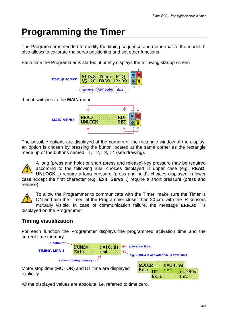
Programming the Timer The Programmer is needed to modify the timing sequence and dethermalize the model. It also allows to calibrate the servo positioning and set other functions. Each time the Programmer is started, it briefly displays the following startup screen then it switches to the MAIN menu The possible options are displayed at the corners of the rectangle window of the display: an option is chosen by pressing the button located at the same corner as the rectangle made up of the buttons named T1, T2, T3, T4 (see drawing).
A long (press and hold) or short (press and release) key pressure may be required according to the following rule: choices displayed in upper case (e.g. READ, UNLOCK,..) require a long pressure (press and hold), choices displayed in lower
case except the first character (e.g. Exit, Servo,..) require a short pressure (press and release).
To allow the Programmer to communicate with the Timer, make sure the Timer is ON and aim the Timer at the Programmer closer than 20 cm. with the IR sensors mutually visible. In case of communication failure, the message ERROR!ERROR!ERROR!ERROR!” is
displayed on the Programmer
Timing visualization
For each function the Programmer displays the programmed activation time and the current time memory: Motor stop time (MOTOR) and DT time are displayed explicitly All the displayed values are absolute, i.e. referred to time zero.
READREADREADREAD R R R RDTDTDTDT UNLOCKUNLOCKUNLOCKUNLOCK SETSETSETSET
FUNC4 t=16.8sFUNC4 t=16.8sFUNC4 t=16.8sFUNC4 t=16.8s ExitExitExitExit tm1 tm1 tm1 tm1
function nr.
e.g. FUNC4 is activated 16.8s after start
MOTOR t=MOTOR t=MOTOR t=MOTOR t=14.9s14.9s14.9s14.9s ExitExitExitExit tm1 tm1 tm1 tm1 DT t=180sDT t=180sDT t=180sDT t=180s
ExitExitExitExit tm1 tm1 tm1 tm1
current timing memory nr.
activation time
MAIN MENU
TIMING MENU
SIDUS TimerSIDUS TimerSIDUS TimerSIDUS Timer F1Q F1Q F1Q F1Q VVVV5555.20 B059 12/09 .20 B059 12/09 .20 B059 12/09 .20 B059 12/09 sw vers. RDT code date
startup screen

Sidus F1Q – free flight electronic timer
5/9
The motor stop time is freely programmable between 0.1s and DT. All the other functions are strictly sequential (FUNC1 > FUNC2 > ,.., FUNC6 > DT). Each activation time is programmable between the activation times of the previous and
following functions. Example.: if FUNC1 = 11.8s and FUNC3 = 13.6s then FUNC2 will be programmable between 11.9s and 13.5s
Automatic Programmer switch off: the Programmer automatically goes to “sleep” to save power if inactive for about 2 min. and wakes up by pressing any key. The message “Battery low!Battery low!Battery low!Battery low!” indicates that the internal battery needs to be recharged.
Timing sequence modification Each available function has its own activation time and a set of servos positions. The motor is started at the beginning of the timing and it has a programmable stop time. During timing the servo positions related to the current function will be kept until the activation of the following function.
Before modifying the timing sequence it must be read from the Timer 1. aim the Programmer at the Timer (make sure it is ON) 2. from the MAIN menu press and hold T1 (READ) until seeing the screen for FUNC1
3. scroll the display with T3/T4 to view the screens related to the other functions, motor
stop time and DT. Reach the function which activation time must be modified 4. press and hold T1 until ‘w’ (write) appears close to the activation time 5. shortly press T3/T4 to increase/decrease the time of one count, or press and hold
T3/T4 to have faster increments/decrements until reaching the wished value 6. shortlly press T2 (Exit) once and repeat the previous steps to modify the activation
time of another function, or shortly press T2 (Exit) again to end the modifications and return to the MAIN menu
7. If one or more time values are modified, they must be written onto the Timer for permanent storing. Press and hold T2 (WRITE) until the message “Writing…” screen is displayed. Should the writing fail, it may be repeated with T2 (WRITE) or aborted with T4 (Exit). To abort the modifications without updating the Timer just make the writing fail by aiming the Programmer away of the Timer , then choose T4 (Exit).
Motor start unlocking
After the completion of a timing sequence, re-enable a new motor start by aiming the Programmer at the Timer (make sure it is ON), then press and hold T2 (UNLOCK) until the message “UnlockinUnlockinUnlockinUnlockingggg…” is displayed.
FUNC1 t=09.5sFUNC1 t=09.5sFUNC1 t=09.5sFUNC1 t=09.5s ExitExitExitExit tm1 tm1 tm1 tm1

Sidus F1Q – free flight electronic timer
6/9
Servo 1 position function
Current timing memory nr.
Servo 2 position
Servo 3 position
Timing memory selection
The Timer is capable to store 5 separate timing sequencies (tm1 to tm5). 1. aim the Programmer at the Timer (make sure it is ON) 2. from the MAIN menu press and hold T4 (SET) (> 3 sec.) until the SET menu is entered 3. press and release T1 (TMemory) to enter the TMemory menu: the current timing
memory is displayed
4. press and release T3/T4 to increment/decrement the timing memory number and
reach the wished value (1 to 5) 5. press and release T2 (Exit) 6. if the timing memory is changed, it will have to be written onto the Timer for permanent
storing. Press and hold T2 (WRITE) until the message “WritinWritinWritinWritingggg…” is displayed. Should the writing fail, it may be repeated with T2 (WRITE) or aborted with T4 (Exit). To abort the modifications without updating the Timer just make the writing fail by aiming the Programmer away of the Timer , then choose T4 (Exit).
Servo positioning modification
This modification is needed to adjust the position that the servos assume during each function, then it is used to trim models using servos directly connected to the moving surfaces. It is not needed when using the mechanical assembly to release levers. 1. aim the Programmer at the Timer (make sure it is ON) 2. from the MAIN menu press and hold T4 (SET) (> 3 sec.) until the SET menu is entered 3. press and release T4 (Servos) to enter the Servo menu (the servos automatically
move to the START position):
START 0START 0START 0START 055550 00 00 00 038383838
111111110000
TMemory BuzzTMemory BuzzTMemory BuzzTMemory Buzz Exit ServosExit ServosExit ServosExit Servos
SET MENU
TTTTMemory Memory Memory Memory Buzz Buzz Buzz Buzz Exit ServosExit ServosExit ServosExit Servos
TMemory = 1 +TMemory = 1 +TMemory = 1 +TMemory = 1 +
Exit Exit Exit Exit ---- TMEMORY MENU
SERVO MENU
SET MENU

Sidus F1Q – free flight electronic timer
7/9
4. press and release T3/T4 to browse the menus for each available positon (START, POS1, POS2, POS3, POS4, POS5, POS6, DT). The servos will move to the programmed positions, that will also be dosplayed with a value between 0 and 130. Reach the wished position (e.g. POS2i n the drawing below)
5. press and release T1 multiple times to have an asterisk ‘****’ close to the servo position to be changed
6. Press and hold T1 until the asterisk turns to ‘wwww’ (WRITE)
Press and release T3 / T4 to change the servo position: the servo will follow with fine movements accordingly. Holding T3 / T4 pressed will produce wider movements. The new position will be permanently modified with no need to be transmitted to the Timer.
Radio motor cutoff and radio DT Press and hold T3 (RDT) (> 1 sec) while the timing is in progress to instantly stop the motor (RMC) and/or dethermalize the model (RDT). The message ‘RDT/RMC TransmittingRDT/RMC TransmittingRDT/RMC TransmittingRDT/RMC Transmitting…’ will be displayed.
The effect of the command depends on the function that is currently in progress:
• if the motor is ON, the command produces its immediate stop and the Timer “jumps” to the next function. Pressing and holding again T3 (RDT) the Timer dethermalizes the model. The programmed DT time remains unchanged
• if the motor is OFF, the command produces immediate model dethermalization
Other settings Enable or Disable the built-in Programmer buzzer
1. From the SET menu press and release T3 (Buzz) to enter the Buzz menu:
2. Press and release T3 (On) / T4 (Off) to enable/disable the buzzer 3. Press and release T2 (Exit) to return to the SET menu, then press and release T2
(Exit) again to exit. This setting will be permanently stored until next modification
Buzz = * OnBuzz = * OnBuzz = * OnBuzz = * On Exit OffExit OffExit OffExit Off
POS2 *POS2 *POS2 *POS2 *061061061061 110110110110
0 0 0 029292929
POS2 w0POS2 w0POS2 w0POS2 w061616161 110110110110
029029029029
BUZZ MENU

Sidus F1Q – free flight electronic timer
8/9
Recharging the Programmer battery Use only the original LiPo charger. Connect the RED/BLACK cable to a 9-12Vdc power source (e.g. to the car cigar lighter through a proper adapter). Full battery charge will take about 2 hours.
Discard the LiPo battery if it has bulges or scratches. The charge must take place in a safe place, far from flammable materials
RICARICA: inserire il connettore a 3-pin del caricatore � alla presa di ricarica del Programmer, accessibile rimuovendo il coperchietto a slitta sul retro. La batteria interna deve rimanere collegata al Programmer.
WARNING: all the 3 charger pins must be inserted in the socket. By inserting only 2 pins the charger will get damaged
Status of the charger leds
• 9-12Vdc power connected, LiPo not connected: Green ON, Red ON • Charge in progress: Red ON, Green OFF • Charge complete: Red OFF, Green ON
Recommendations Control board
lay the control board in the fuselage with the optics (IR sensor and led) closet o a side wall, so that these devices are visible from outside through a small transparent window. Do not expose under direct sunlight.
Programmer and LiPo Battery The Programmer battery ensures about 200 DT activations and power for programming activities of months. If the system is not going to be used for long time, switch the Programmer OFF through the internal switch.
RDT Antenna The RDT antenna (twisted or plain steel wire about 170 mm. long) must run vertical out of the fuselage and be electrically isolated from carbon. Solder the antenna to the plug that will be inserted in the socket along the edge of the control board (see picture at pag. 2). Failure to follow the above will decrease the maximum range of the whole RDT system.
Installing the Timer on multiple models One additional Timer control board (plus LiPo and mechanical gear) with the same RDT code is required to provide another model with the SidusSidusSidusSidus electronic timer. The RDT code is unique for each modeller to allow all his Timer control boards to be used with a single Programmer. In addition it makes it possible to use the SidusSidusSidusSidus system simultaneously with other modellers having the same or other systems.
3-pin recharge socket

Using the 5-function mech. assembly Servo position programming The Sidus F1QSidus F1QSidus F1QSidus F1Q Timer is capable of 7 functions (FUNC1,.., FUNC6, DT) and each function has a related set of positions for up to 3 servos. When using the 5-function mechanical assembly, only one servo is used and two of these functions (FUNC5 and FUNC6) remain unused. The Timer is programmed to have the disc assuming the same position for FUNC4, FUNC5 and FUNC6 so that once the 4th arm is released, the disc remains in the same position (whatever the activation time programmed for FUNC5 and FUNC6) until DT activation (when the last step releases the 5th arm i.e. DT). • assign to POS5 and POS6 the same position assigned to POS4. During timing, the
servo will move from START to POS4 releasing the first 4 arms. It will remain steady until reaching DT that will release the 5th arm, no matter the activation time programmed for FUNC5 and FUNC6
Wirings
Observe polarities for the SERVO and ESC plugs!!!
the START SWITCH plug has no polarity and can be reversed