Embed Size (px)
Citation preview

Installation Guide2016
Siding Components

MID-AMERICA SIDING COMPONENTSINSTALLATION GUIDE
This guide will show you the products of the Mid-America Siding Components® family. It provides specific installation steps and application details. Our main goal is to make your installation
experience quick, easy and trouble-free.
Thank you for choosing Mid-America products.

Introduction 2
Table of Contents 3
Louver/Panel Installation with Screws or Shutter-Loks® 4
Board-N-Batten™ 5
Shutter Top 6
Shutter Hardware 7
Ferrule 8
Shutter Clip 9–10
Framed Shutter Installation 11
Exterior Dentil 12–13
Exterior Dentil Corners 14
Window Header 15–17
6" & 9" J-Channel Back Plate 18–19
Pilaster with J-Channel Back Plate 20–25
TABLE OF CONTENTS

MidAmericaComponents.com
4
1/4" holes
1/4" holes
Figure 2B
NOTE: Shutters need room to expand/contract, be sure not to over tighten fasteners. To prevent shutters from warping, proper installation must be followed. Wall anchors will be required for shutters installed on any type of masonry.
FOR USE ON A VARIETY OF SURFACES INCLUDING: Wood, aluminum, vinyl, stucco, hardboard, brick or masonry.
REQUIRED FOR INSTALLATION:Electric drill, 1/4" drill bit (Shutter-Loks), 11/64" drill bit (screws), hammer, Shutter-Loks and/or screws.
Louver/Panel Installation with Screws or Shutter-Loks®
Place the shutter next to the window and mark desired location against the wall or window. See Figure 1.
Note: Up to 43", use four Shutter-Loks or screws. 44" and greater, use six Shutter-Loks/screws per shutter.
STEP 1
To help ensure proper alignment, mark and pre-drill holes into the shutter before attaching it to the wall. Shutter-Loks require 1/4" hole. Screws require 11/64" hole and 1/4" hole if over 44". See Figures 2A and 2B.
When installing shutters shorter than 44", drill four (4) 1/4" holes in the locations shown in Figure 2A. If the shutter is 44" or greater, drill six (6) 1/4" holes for Lok application or four (4) 1/4" holes and two (2) 11/64" holes for screws. See Figure 2B.
STEP 2
top of shutter
window
Figure 1
STEP 3
Position the shutter in location against the wall, and drill through the shutter into the wall surface to a depth of 3-1/4".
1/4" holes
1/4" holes
11/64" holes
Four Shutter-Lok Application
Figure 2A
Six Screws Application
To remove shutters, do not attempt to pull out the Shutter-Loks. Instead, simply sl ide a pair of snips behind the shutter to cut the Shutter-Lok off at the shank.
NOTE:
STEP 4
Tap the Shutter-Lok gently with a hammer or drive in the screw so as not to over drive or over tighten.

MidAmericaComponents.com
5
Four ScrewApplicationFor less than 55"
1/4" holes
1/4" holes
Six ScrewApplicationFor 55" or greater
1/4" holes
1/4" holes
11/64" holes
Board-N-Batten™
FOR USE ON A VARIETY OF SURFACES INCLUDING: Wood, aluminum, vinyl, stucco, hardboard, brick or masonry.
REQUIRED FOR INSTALLATION: Electric drill, 1/4" drill bit, 11/64" drill bit, screwdriver and screws.
NOTE: Shutters need room to expand/contract, be sure not to over tighten fasteners. To prevent shutters from warping, proper installation must be followed. Wall anchors will be required for shutters installed on any type of masonry.
Place the shutter next to the window and mark desired location against the wall or window as shown in Figure 1.
Note: Up to 43", use four screws. 44" and greater, use six screws per shutter.
STEP 1
To help ensure proper alignment, mark or pre-drill holes into the shutter before attaching it to the wall. When installing shutters shorter than 43" drill (4) 1/4" holes in the locations shown in “Four Screw Application”as shown in Figure 2A. If shutters are 44" or greater, drill (6) 1/4" holes and (2) 11/64" holes in the locations show in “Six Screw Application” as shown in Figure 2B.
STEP 2
Use enclosed screws to secure the shutter to the wall surface. Do not over tighten. Shutters must have room to expand and contract with changing weather. Position the shutter in location against the wall, and drill through the shutter into the wall surface to a depth of 3-1/4”. These instructions use three-board shutters as the example. The same techniques are used for shutters with four and five boards.
STEP 3
Figure 1
Figure 2A Figure 2B

MidAmericaComponents.com
6
Shutter Top
STEP 1Attach the top to the shutter using the clips provided. Align shutter and top on a flat surface. Join pieces together by pushing each clip on as far as it will go. Use two clips per top. See Figure 1.
Proceed to Step 1A for Raised Panel, Solid and Transom top installation with transom clips.
STEP 1AA transom clip will also need to be installed in addition to the two (2) clips. Start by pushing one end of the transom clip onto the shutter, clamping the shutter to the top. Work the transom clip down until the entire clip is fastened to the shutter. Be sure the transom clip is pushed on as far as it will go. See Figure 1.
STEP 2
Fasten shutter to wall using instructions supplied with shutter. To prevent shutter from dimpling, do not over tighten.
REQUIRED FOR INSTALLATION:Electric drill, 1/4" drill bit (Shutter-Loks®), 11/64" drill bit (screws), screwdriver, screws or Shutter-Loks.
NOTE: Note that Louver and Elliptical tops, do not require transom clips.
Shutter
Top
Clip
(front of assembly)
(back of assembly)
1/4" hole
Transom Clip
Clip
Support rib will need to be removed
Clip
Figure 1
1/4" hole
Transom Clip
Clip
Support rib will need to be removed
Clip
Figure 2
Drill one (1) 1/4" hole as shown in Figure 2. For Transom tops, drill two (2) holes as shown in Figure 3.
STEP 3
Figure 3
1/4" hole

MidAmericaComponents.com
7
S-Hook Hinge
Figure 1
Shutter Hardware
REQUIRED FOR INSTALLATION:Electric drill, Phillips screwdriver, 1/8" drill bit
Kit contains (4) hinges, (2) S-hooks, (10) screws
STEP 1
Determine where hinges and S hook will be installed. Hinges are typically installed near ends of shutters. S-hooks are installed on the bottom outer corner. See Figure 1. NOTE: that if placing hinges over fasteners, be sure pilot holes don’t interfere with the fasteners.
STEP 2
Using the marks on front of hinges as guides, drill pilot holes through the hinge and shutter, using a 1/8" drill bit. The back of the S-hook has a fin, the screw will be placed here. After the position of the S hook is determined, drill through the fin and into the bottom of the shutter using a 1/8" drill bit.
STEP 3
Securely attach hardware using screws provided.
I f screw head coating is scratched during instal lation, touch-up with satin black paint.
NOTE:

MidAmericaComponents.com
8
Ferrule
FOR USE ON ANY SURFACE INCLUDING: Wood, aluminum, vinyl, hardboard, brick, masonry and stone.
REQUIRED FOR INSTALLATION:Electric drill, 1/4" drill bit, 11/64" drill bit, hammer, Shutter-Loks® or screws and ferrule.
STEP 1
Place shutter next to window, mark desired location against the wall or window.
STEP 2
STEP 3
STEP 4
With shutter in location against the wall, drill through shutter into the wall to depth of 3-1/4". In brick, the hole diameter should be no greater than 1/4", and drilled into mortar joints. Do not attach shutter at this time. See Figure 1.
Place Ferrule behind shutter and line up with the holes drilled for the Shutter-Loks or screws. Trim ferrule to properly fit gap between back of shutter and wall to which it is being attached. Ferrules may not all be same length. Shutter-Loks used in masonry must penetrate into the wall to a depth of at least 7/8". Note that if using screws, drill a hole 11/64". Follow shutter installation instructions based on height.
Ensure ferrule is trimmed to desired length and shutter is parallel to wall. Insert Shutter-Lok or screw into the hole in the shutter and through ferrule into the wall. Tap Shutter-Lok gently with a hammer or drive in a screw to secure the shutter to the cladding. To prevent shutter from dimpling, do not over tighten.
Figure 1

MidAmericaComponents.com
9
Shutter Clip
REQUIRED FOR INSTALLATION:Screwdriver, electric drill, level and pencil. (4) shutter clips for shutters up to 43" and (6) shutter clips for shutters 44" or greater. Also needed are (9) No. 10 or equivalent (M5 metric) screws. Other fasteners may be needed for specific surfaces (not included).
STEP 1
Push a shutter clip onto the ribs at each corner of the shutter. The mounting tab should extend beyond the shutter. See Figure 2. Shutter clips will be removed later, so DO NOT fasten shutter clips completely onto the shutter at this time.
Correct Placement for Shutter Clips
Do not completely fasten Shutter Clips to shutter at this time
Figure 1
Figure 2

MidAmericaComponents.com
10
pencil marks
top of shutter
window
window trim
STEP 5
Once the shutter clips are positioned and secured to the mounting surface, attach shutter by placing shutter over shutter clips and pressing the shutter ribs on to each shutter clip. Press shutter firmly against mounting surface, making sure all six (6) clips are engaged.
Shutter Clip, Continued
Figure 3
Figure 4
Fasten with bracket up Optional
Next to window Away from window
STEP 2
Hold the shutter where you want it to be attached on the mounting surface. Mark the center hole of each shutter clip in each clip. Draw lines vertically between top and bottom marks. After completing this step, remove shutter clips from shutter. See Figure 3.
STEP 3
Place the front of the shutter against the mounting surface and align it next to where it will be installed. On the vertical lines drawn in Step 2, sketch marks corresponding to the mounting areas of the shutter. See Figure 3.
STEP 4
Read complete instructions for Step 4 and examine Figure 4 before installing shutter clips to mounting surface. Fasten shutter clips centered on the vertical line and between the sketch marks drawn in Step 3. Use one screw next to the window, and two screws in the shutter clips away from window. See Figure 4. shutter clips should be free to move with changes in temperature. Mounting bracket on shutter clip should be placed in upright position. Special mounting procedures or techniques may be required on different mounting surfaces.

MidAmericaComponents.com
11
TECHNICAL BULLETIN
Framed Shutter Installation
Maintain a minimum clearance of 1/4" along both sides and 3/8" at the top and bottom of the shutter to allow for movement.
3/8" Top and bottom
1/4" Sides
Applies to Louver, Panel, Board-N-Batten™ Shutters.

MidAmericaComponents.com
12
Scalloped and Square Exterior DentilYour home’s style will determine which of the three (3) exterior dentil installation approaches are best. Installation always proceeds left to right. Installation approaches will also vary based on temperature. See table below.
BOX CONTAINS: (8) pieces of dentil in original or scalloped style, (24) screw covers and (24) screws.
REQUIRED FOR INSTALLATION:Electric drill and saw.
The starting point will depend on which corner is used. Step 1A should be used when starting on an endcap or inside corner. Use Step 1B when starting on an outside corner.
STEP 1
An endcap is used when exterior dentil will be terminated. An inside corner is used when the exterior dentil is continued into a 90º corner. Starting at the point where the Dentil will be terminated or carried to an inside corner, measure back 3", placing a mark on the wall. See Figure 1. Place exterior dentil at this mark and secure it in place by screwing into the screw pockets in the dentil. See Figure A. The Dentil must have room to expand and contract with temperature changes. Be careful not to screw the dentil in too tightly.
STEP 1A
Scalloped Dentil Square Dentil Screw Pocket
Screw CoverScrew Cover
Endcap Outside Corner Inside Corner
An outside corner is used when exterior dentil is continued around a 90º corner. Place the exterior dentil at a position flush with the corner of house. Secure dentil in place by screwing into the screw pockets in the dentil. Because the dentil must expand and contract with temperature changes, be careful not to screw the dentil in too tightly. See Figure 2.
STEP 1B
3"
Figure 1
Figure 2
Figure A
Installation Temperature - Spacing85º or greater 1/8"
40º - 84º 3/16"40º or below 1/4"

MidAmericaComponents.com
13
Scalloped and Square Exterior Dentil, Continued
Once you’ve established a starting place, slide the second piece of dentil in place. Two (2) alignment lines can be found on the Dentil’s left end. See Figure 3A.
Continue installation by sliding dentil from left to right, leaving the appropriate space in between. Secure by screwing into the screw pocket of the dentil. See Figure 3B.
STEP 2
As each section of dentil is secured in place, install screw covers. First, place the hook into bottom of dentil screw pocket. Next, push the flat tab into the top of screw pocket until it is securely locked into place. See Figure 4A and 4B.
STEP 3
At end of each wall, it may be necessary to cut the dentil. When cutting exterior dentil, measure and cut from the right side. When terminating with an endcap, make sure the dentil ends 3" from the end of the wall. See Figure 5.
STEP 4
When using a cut segment of dentil to continue an inside or outside corner, you may have to trim that segment. See Figure 6. Cutting the dentil at this 1/2" dimension will eliminate need for later modifications of the corner.
STEP 5
Alignment Lines
Space
Space
Back of screw cover
Flat tab
Hook
ToothDiscard this portion
1/2"
3"
Figure 3A Figure 3B
Figure 4A Figure 4B
Figure 5
Figure 6
Screw Pocket

MidAmericaComponents.com
14
Dentil Corner
REQUIRED FOR INSTALLATION:Electric drill, 1/8" drill bit, rivet gun and utility knife.
Scalloped Exterior Dentil
Inside Corner Outside CornerEndcap
Exterior dentil corners are designed to complete installation of the exterior dentil square or scalloped trim. Three (3) terminations available: endcap, inside corner and outside corner. See Figures 1–3.
Drill 1/8" hole on face of endcap and use rivet gun to attach rivets to dentil trim. When securing bottom surface of endcap to exterior dentil, rivets must enter a tooth.
See Figures 1–3 to identify placement of rivets on three different endcaps.
Note: When installing endcaps, there may be interference between cap and dentil tooth. See Figures 1–3.
STEP 1
If interference takes place on an inside corner, remove the wall on the endcap by using a knife to score and cut from the back side. The wall on the outside corner can be removed by snapping it off or using a knife as described above. See Figures 2A through 2C.
STEP 2
Remove shaded area if needed by scoring and cutting with knife
Remove shaded area if needed by snapping it off or by scoring and cutting with a knife.
Outside CornerInside Corner
Remove shaded area if needed by scoring and cutting with knife
Inside Corner
Figure 2 Figure 3Figure 1
Figure 2AFigure 2B
Figure 2C
BOX CONTAINS: (1) Right endcap or (1) left endcap, (4) rivets
CORNER BOX CONTAINS:(1) Inside corner or (1) outside corner, (4) rivets
Endcap Wall
Endcap Wall
Cut here to create a right side Endcap
Cut here to create a left side Endcap
Figure 3
Endcap Wall
If necessary, endcaps can be created by cutting outside corners at the scribe lines. See Figure 3.
NOTE:

MidAmericaComponents.com
15
6" & 9" Window Headers with Keystone
HEADER BOX INCLUDES:(1) Flat panel or dentil header, (1) header base, (3) fastener packs.
REQUIRED FOR INSTALLATION:Electric drill, saw, measuring tape, 1/4" drill bit and utility knife.
Measure width of window across longest measurement to create Dim (Dimension) A. Draw a horizontal line 1/8" above window trim, to be used to ensure appropriate space between window header and window trim. See Figure 1. If header is too long for window, proceed to Step 2A. If not, proceed to Step 4.
STEP 1
Installation & Cutting Instructions for 6" and 9" Headers with KeystoneCombines a basic header installation with keystone and cutting.
If window header doesn’t match the precise size of your window, you will have to cut the window header. After assembling the window header and window header base, mark the center on the assembly. See Figure 2A.
STEP 2A
Dim "A"
CLDraw horizontal line 1/8" above window trim
Subtract Dim. A from Dim. B and divide the measurement in half. The result will be Dim. C. See Figure 2B.
STEP 2B
Transfer Dim. C to the window header as-sembly twice, once on each side of the cen-terline. See Figure 2C.
STEP 2C
Dim "B"
Window Header and Base assembly right from box.
CL
Dim. "B" Dim. "A"-2 = Dim. "C"
Cut window header and window header base.
STEP 3
CL
Dim "C"Dim "C"
Figure 2A
Figure 2B
Figure 2C
Figure 1

MidAmericaComponents.com
16
6" & 9" Window Header with Keystone, Continued
After cutting window header to correct length, disengage the locking tabs and remove the window header from the window header base. Release locks by starting at the open end of the cut header assembly and pull the header wall from the header base. Continue these steps to the end of the cut window header assembly. See Figure 3.
STEP 4
Using the elongated slots in header base, secure the base to the cladding, using the screws provided. An alternative method would be to use Shutter-Loks®. Raised portions of the header base featuring the round holes receive the Shutter-Loks. Attach Shutter-Loks by drill ing 1/4" holes into the wall. To allow for expansion and contraction, do not fasten screws or Shutter-Loks too tightly. See Figure 4A.
The window header may rock on the high point of the siding. To overcome this issue, insert screws or Shutter-Loks into wall evenly. See Figures 4A and 4B.
STEP 5
slots for optional screw application
CORRECT INCORRECTCORRECT INCORRECT
Figure 3
Figure 4
Figure 4A Figure 4B
STEP 6
Once window header base is secured to wall, attach the window header by snapping into place. See Figure 5.
Figure 5

MidAmericaComponents.com
17
6” & 9” Window Header with Keystone, Continued
STEP 7
Center keystone base over window header assembly. To aid installation, use the tab at the bottom of the keystone base, ensuring the bottom of the tab and bottom of the window header are flush. Screw keystone base into place using enclosed screws. Note that Shutter-Loks can be used to secure the keystone base to the window header. Drill two 1/4" holes through the window header and tray to accept Shutter-Loks. See Figure 6
STEP 8
STEP 9
If the dentil teeth land on the sides of the keystone, it will not properly snap in place unless trimmed. Trim thinned areas on keystone cover with utility knife as shown. See Figure 7.
Snap keystone over keystone base, making sure the locking tabs engage. See Figure 8.
Cut out both thinned window areas shown using the wallas a guide.
Figure 7
Figure 6
Figure 8

MidAmericaComponents.com
18
6" and 9" J-Channel Back Plate For Window Headers
Measure length of header to be installed on base. Record this dimension as Dim. A, to determine the amount to be removed. See Figure 1. If the header and back plate is cut to precise length, skip to Step 3. If you need to cut the header to length, refer to Keystone & Cutting Instructions included with header.
STEP 1
THE BOX CONTAINS: (1) J-channel back plate, butyl tape and screws.
REQUIRED FOR INSTALLATION:Electric drill, saw, 1/4" drill bit and tape measure.
If backplate does not need to be cut, proceed to Step 3. If back plate needs to be cut to length, refer to 2A or 2B of 6"/9" Window Header Installation guide. Use same process as cutting a window header. Then continue with Step 2.
Flip back plate over, exposing the back side. Apply 12" length of foil-backed butyl tape provided with header base. Work from top of mount to bottom, keeping tape tight to inside of part. This ensures a watertight installation of the siding mount. Note that if siding mount ribs are too close to permit the application of the full tape width, trim ribs with utility knife. See Figure 2.
STEP 2
Draw horizontal level line 1/8" above window trim to locate bottom of the mount. In addition, draw a vertical line at center of window for alignment. See Figure 3.
STEP 3
If the Back Plate aligns with the J-channel, remove the tab on the end of the mount. See Figure 4. Use knife slots on the inside of the tab as a guide. If the back plate exceeds the window flange or J-channel, the tab can be left in place to divert water.
STEP 4
Dim "A"
TAB REMOVED
Start Taping Here.
Keep Tape Tight in Corners
Support Ribs
Figure 1
Figure 4
Figure 2
Centerline of window
Horizontal line1/8" above window
Figure 3

MidAmericaComponents.com
19
6" and 9" J-Channel Back Plate for Window Headers, Cont.
Secure back plate to sheathing. Align back plate with center line and horizontal lines drawn in Step 3. Nail in the center of nailing slots to allow for expansion and contraction. See Figure 5.
STEP 5
Continue securing back plate above window. Cut top ends of J-channel to create a tab for tucking under header mount.
STEP 6
Once J-channel is secure, use two (2) 2”-x-2” included butyl tape strips to cover seams between nailing flanges of the J-channel and the header mount on either side of opening. See Figure 6.
STEP 7
Install siding around opening.
STEP 8
Attach Window Header to back plate. See 6"/9" Window Header guide for complete instructions.
STEP 9
Figure 6
Figure 5

MidAmericaComponents.com
20
Pilaster with J-Channel Back Plate
THE PILASTER CONTAINS: (2) transition tops (one left, one right), (2) pilasters, (2) pilaster bases, (2) bottom corners (one left, one right), (2) bottom corner bases, (2) 24pk. screws, (3) 12 pk. Shutter-Loks®, and (4) transition clips.
Optional components for installation not included with the pilaster are (1) header back plate, 6" or 9", (2) 6"x90" pack plates for pilasters, (1) 6" or 9" header, (1) 6" keystone, (1) 6" or 9" keystone.
Note:The illustrations contained in these instructions use a 9" header and base for examples. A 6" header and base can be used just as easily. Siding has been removed from illustrations for visual clarity.
If not using J-channel back plate, follow installation instructions disregarding back plate references.
REQUIRED FOR INSTALLATION:Electric drill, 1/4" drill bit, saw, measuring tape and square.
Measure door height, including any brick mold or trim around door. Record this as: Dim. A. See Figure 1.
STEP 1
Cut bottom radius of J-channel back plate off. Using Dim. A, subtract 1/4" from measurement and cut back plate to length. Repeat for other side. See Figure 1A.
STEP 2
(If not using back plate, proceed to Step 4.) Screw pilaster mounts to sheathing 1/8" away from sides of door, and 1/4" away from the bottom of door. This should leave top of mount flush with top of brick mold. Be sure not to over fasten, allowing for expansion and contraction.
STEP 3
1/4"
1/8"
1/8"
1/4"
Dim. 'B'Dim. 'B'
Left Right
Flat sides
Assembled Pilaster andPilaster Base
Figure 1 Figure 1A
Figure 2
Dim. A
Dim. A
Cut to square the end
J-ChannelBack Plate

MidAmericaComponents.com
21
Pilaster with J-Channel Back Plate, Continued
Cut the pilaster assemblies to the correct length. Use the following formula: 96" (length of pilaster), minus Dim. A, minus 1/2", equals Dim. B.
Measure and cut Dim. B from top of both pilasters. See Figure 3. Before cutting, ensure pilasters are oriented in correct position, with the flat side of the pilaster against door. If Dim. B is greater than 12", cut the remaining material off the bottom of pilaster.
STEP 4
Separate the pilasters from the pilaster base. Position the pilaster base on top of J-channel back plate or directly onto the cladding as show in Figure 4. Place screw in the center hole of pilaster base. Do not substitute Shutter-Lok for screw.
STEP 5
Place remaining screws in slots, or drill 1/4" holes into the wall to a depth of 3" to accept Shutter-Loks. Use Shutter-Loks only in the round holes molded in raised areas of pilaster base. For locations, see Figure 4. Complete this step for both sides of door. Screws should be centered in slot. To allow for expansion and contraction, fasteners should not be over tightened.
STEP 6
1/8"1/8"
1/4"
center hole for screw placement
Shutter Lok location
slots for screws
center of door1/4"
1/8"1/8"
1/4"
1/4"
d
Figure 3
Figure 4
Dim. 'B'Dim. 'B'
Left Right
Flat sides
Assembled Pilaster andPilaster Base
MidAmericaComponents.com
22
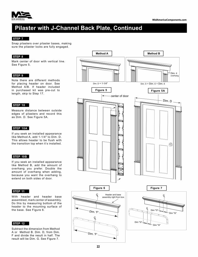
Snap pilasters over pilaster bases, making sure the pilaster locks are fully engaged.
STEP 7
Mark center of door with vertical line. See Figure 5.
STEP 8
Pilaster with J-Channel Back Plate, Continued
Note there are different methods for placing header on door. See Method A/B. If header included in purchased kit was pre-cut to length, skip to Step 17.
STEP 9
Measure distance between outside edges of pilasters and record this as Dim. D. See Figure 5A.
STEP 10
If you seek an installed appearance like Method A, add 1-1/4" to Dim. D. This allows header to be flush with the transition top when it’s installed.
STEP 10A
If you seek an installed appearance like Method B, add the amount of overhang you prefer. Double the amount of overhang when adding, because you want the overhang to extend on both sides of door.
STEP 10B
With header and header base assembled, mark center of assembly. Do this by measuring bottom of the header to the mounting surface of the base. See Figure 6.
STEP 11
Subtract the dimension from Method A or Method B. Dim. D, from Dim. F and divide the result in half. The result will be Dim. G. See Figure 7.
STEP 12
1/8"1/8"
1/4"
center hole for screw placement
Shutter Lok location
slots for screws
center of door1/4"
1/8"1/8"
1/4"
1/4"
d
Figure 5
"
Method A Method B
Dim. D + 1-1/4" Dim. D + Dim. E + Dim. E
Dim. E overhang
Method A
"
Method A Method B
Dim. D + 1-1/4" Dim. D + Dim. E + Dim. E
Dim. E overhang
Method B
Dim. D
Figure 5A
CL
Dim "G"Dim "G"
CL
Dim "G"Dim "G"
Figure 7
CL
CL
Dim. 'F'
Dim. 'F'
Header and base assembly right from box.
Figure 6

MidAmericaComponents.com
23
Pilaster with J-Channel Back Plate, Continued
Transfer Dim. G to header assembly and to J-channel back plate. Dim. G will be transferred twice, once on each side of the centerline. See Figure 8.
STEP 13CL
Line created from Dim. GLine created from Dim. G
Remove shaded areas
STEP 14
Cut header/base assembly and back plate assembly at lines created by Dim. G.
STEP 14
Once you have cut components to correct length, disengage locking tabs and remove header from the header base. To release locks, start at open end of cut header assembly and pull the wall of header away from header base. Continue this step until you reach the end of the cut header assembly. See Figure 9. If not using J-Channel back plate, proceed to Step 18.
STEP 15
Header
Header Base Siding Mount
Flip J-channel back plate over, exposing back side of mount. Apply the 12" length of foil-backed butyl tape supplied with header base. Start at top of mount, working all the way to bottom. Make sure tape fits tightly in inside corners of the part, ensuring a watertight installation of siding mount. Note that if the ribs of siding mount are too close to allow application of the full width of tape, use a utility knife to trim from the corresponding ribs. See Figure 10.
STEP 16
Start Taping Here.
Keep Tape Tight in Corners
Figure 8
Figure 9
Figure 10

MidAmericaComponents.com
24
Pilaster with J-Channel Back Plate, Continued
Align centerline of back plate with centerline of door. Leave a gap of approximately 1/8" between bottom of back plate and top of door, providing the header with clearance when snapped into place. When mount is in proper location, attach to the sheathing with screws provided. See Figure 11.
STEP 17
Align centerline of header base with centerline of door. Align bottom of header base with bottom edge of J-channel siding or cladding, leaving 1/8" between the header base and the top of the door trim. A preferred method of attaching base to house is with Shutter-Loks supplied in the kit. To install Shutter-Loks, drill 1/4" holes in the wall to a depth of 3". Use Shutter-Loks only in the round holes molded into the raised areas of header base. Space the Shutter-Loks accordingly along the header base. See Figure 12. Another method involves use of screws. Use elongated slots in base, using the screws supplied in kit to attach base to house. To allow for expansion and contraction, avoid over tightening screws.
STEP 18Slots for optional screw application
centerline
Use Shutter Loks at raised areas
slots for screw application
centerline
Place transition top pieces on header in approximate location of pilasters. If header has optional welded-on endcaps, trim the bottoms of endcaps with a utility knife to ensure the transition top pieces are flush. See Figure 13 and Figure 13A. Clip them to header using clips provided, using two clips per transition top.
STEP 19
Snap header over header base. Transition top pieces may have to be repositioned to line up with pilasters.
STEP 20
Center keystone base over header. Bottom of keystone base and bottom of header should be flush. Use the supplied screws to screw keystone base into place. See Figure 14.
STEP 21
(Only applies to headers with end caps)
Transition ClipTransition Top
Header
Figure 11
Figure 12
Figure 13
Figure 13A
Figure 14

MidAmericaComponents.com
25
Pilaster with J-Channel Back Plate, Continued
Snap keystone over keystone base, making sure lock tabs engage.
STEP 22
Note directions on back of bottom corner base that show correct orientation for the left and right side of door. Line up bottom of bottom corner base with bottom of pilaster. Use the elongated screw slots to determine proper screw placement, secure corner base to pilaster. See Figure 15.
STEP 23
Once bottom corner base is secured in place, snap the bottom corner over the bottom corner base. Repeat step on other side of door. See Figure 16.
STEP 24
Bottom CornerBase
Finished
Figure 15
Figure 16

MidAmericaComponents.com
26
Notes:

MidAmericaComponents.com
27

© 2016 Tapco International Corporation M4512 5/16
MID-AMERICA SIDING COMPONENTSINSTALLATION GUIDE
MidAmericaComponents.com
For more information contact our customer service department: 800.521.8486
Fax: 888-459-3647Mid-America | 29797 Beck Road | Wixom, MI 48393