Embed Size (px)
Citation preview

Side Channels in Cryptography
Debdeep Mukhopadhyay
Dept of Computer Sc and Engg
IIT Madras
Outline of the Talk
• What is meant by Side Channel Attacks?
• Power Based Side Channel Analysis
• DFT in Cryptographic Algorithms and Scan Chain Based Attacks

Fabrication(Threat)
Authenticity(Policy)
MAC(Mechanism)
Modification(Threat)
Interception(Threat)
Establishing Goals
BobAlice
Mallory
COMUNICATION CHANNEL
Security Attacks
Confidentiality(Policy)
Encryption(Mechanism)
Integrity(Policy)
Hash(Mechanism)
Policy• Confidentiality• Integrity• Authenticity
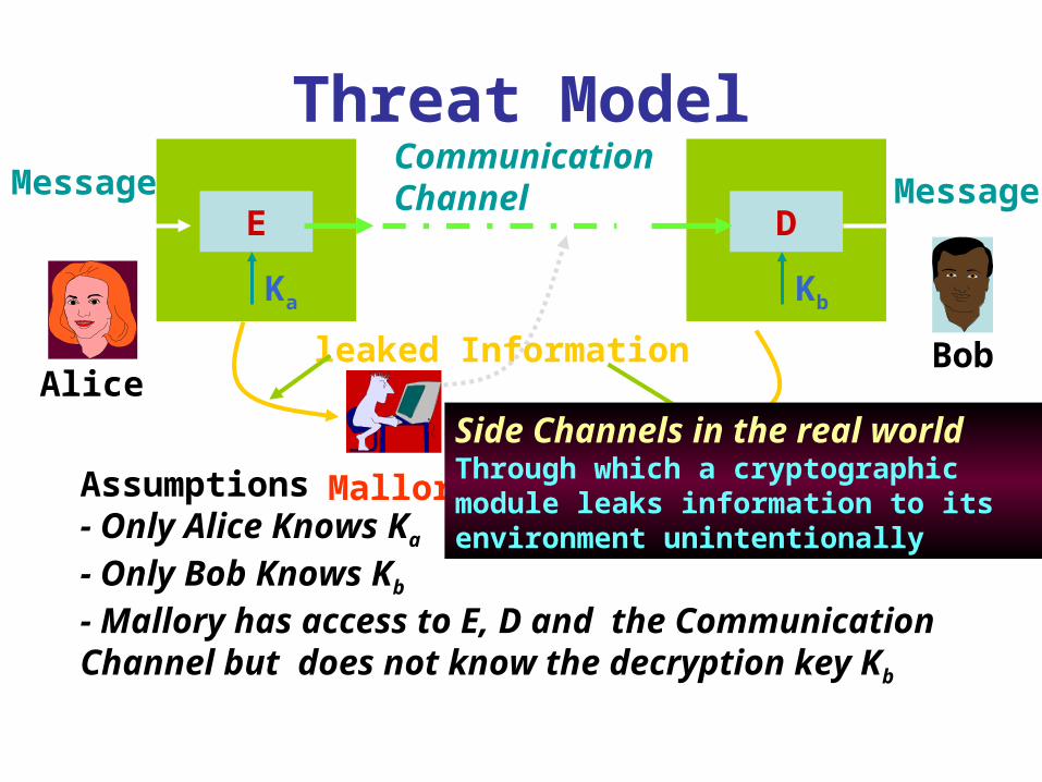
Threat Model
Assumptions- Only Alice Knows Ka
- Only Bob Knows Kb
- Mallory has access to E, D and the Communication Channel but does not know the decryption key Kb
E
Ka
D
Kb
CommunicationChannelMessage Message
leaked Information
Mallory
AliceBob
Side Channels in the real worldThrough which a cryptographic module leaks information to its environment unintentionally

Side Channel Sources
E/D
K
Real World System
Threat Model & Security Goal
Protocols
HardwareHuman User
Software
Deployment & Usage
It is impossible to design a totally secure system with humans in it
• Key dependent Variations
computation time
• Power consumption• EM Radiations
Traditionally we have handled only
Cryptographic Algorithms

Power Analysis AttackIdea: During switching CMOS gates draw spiked current
Trace of Current drawn - RSA Secret Key Computation
Only SquaringSquaring and multiplication
Reported Results : Every Smartcard in the market BROKEN

Possible Side Channels
• Power
• Time
• Faults
• Electro-Magnetic radiations
• Sound
• Scan Chains
and may be many more…

Side Channel Analysis (SCA)• Simple Side Channel Analysis
– makes use of characteristics that are directly visible in one measurement trace.– The secret key needs to have some simple, exploitable relationship with the
operations that are visible in the measurement trace. – Typically, vulnerable implementations include key dependent branching.
• Differential Side Channel Analysis – looks for side channel differences that are not directly visible in one
measurement trace.– statistical methods have to be applied. – targets one specific intermediate result that shows up in a specific part of the
measurement traces. – A typical approach chooses a selection function, i.e., an intermediate result at the
beginning or end of the cryptographic algorithm. – The result of the selection function depends on the known input/output data and
a small number of hypotheses on the key value. – The outcome of the selection function leads to a partitioning of the overall
measurement data for each hypothesis used.– For the correct key hypothesis, different statistical properties of the two
partitioning sets are expected at that points in time which depend on the result of the selection function.
Power Attacks (PA)
• During the last few years (eight ?) lot of research has been conducted on Differential Power Attacks (DPA)
• Exploit the fact that (dynamic) power consumption of chip is correlated to intermediate results of the algorithm
• To measure a ckt’s power, a small resistor (50 ohm) is inserted in series with the power or ground input

Lab Set Up for Power AnalysisCan sample voltage
differences at around 1GHz with less than
1% error. It also transfersData to a PC. Cost around
$400.
Courtesy: Side-Channel Analysis Lab,

Simple Power Analysis (SPA)
• Directly interprets the power consumption of the device
• Looks for the operations taking place and also the key!
• Trace: A set of power consumptions across a cryptographic process
• 1 millisecond operation sampled at 5MHz yield a trace with 5000 points

DES Numerology
• DES is a block cipher• 64 bit block length• 56 bit key length• 16 rounds• 48 bits of key used each round (subkey)• Each round is simple (for a block cipher)• Security depends primarily on “S-boxes”• Each S-boxes maps 6 bits to 4 bits• Each S-box has a share of 6 bits of the key

OneRoun
d of
DES
28
L R
expand shiftshift
key
key
S-boxes
compress
L R
28
2828
2828
48
32
48
32
32
32
32
48
32
Ki
P box
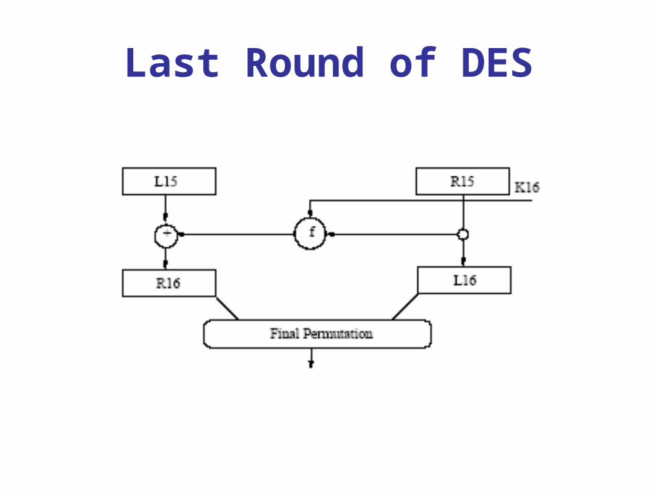
Last Round of DES

Power Traces of DES
16 Rounds of DES can be easily observed

Power Traces for DES
The 28 bit key registers C and D are rotated once in round 2, while twice in round 3. These conditional branches depending on the key bits
leak critical information.

Power consumption
Simple Power Analysis
Data input
Data output
Terminal
IC chip
Power supply
011101101111101110111011101111000001
Measure power consumption
Guess secret information stored on IC chip memory
1 0 1 1 0Secret information

Differential PowerAnalysis (DPA)

DPA OverviewDPA Overview
Introduced by P. Kocher and colleagues
More powerful and more difficult to prevent than SPA
Different power consumption for different state (0 or 1)
Data collection phase and data analysis phase
Procedure
Gather many power consumption curves
Assume a key value
Divide data into two groups(0 and 1 for chosen bit)
Calculate mean value curve of each group
Correct key assumption → not negligible difference

DPA Procedure for DESDPA Procedure for DES1. Make power consumption measurement of about 1000
DES operations, 100000 data points / curve, (Ciphertexti, Curvei)
2. Assume a key for a S-box of last round
3. Calculate first S-box first bit output for each plaintext using the assumed key
4. Divide the measurement into 2 groups (output 0 and 1)
5. Calculate the average curve of each group
6. Calculate the difference of two curves
7. Assumed correct key → spikes in the differential curve
8. Repeat 2-7 for other S-boxes
9. Exhaustive search for 8 bits of key
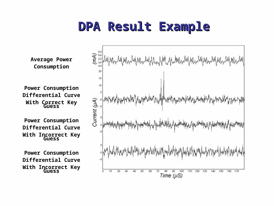
DPA Result ExampleDPA Result Example
Average PowerConsumption
Power ConsumptionDifferential Curve
With Correct Key Guess
Power ConsumptionDifferential Curve
With Incorrect Key Guess
Power ConsumptionDifferential Curve
With Incorrect Key Guess

DPA in details
• DPA selection function : D(C,b,Ks) is defined as computing the value of the – bth output bit, depending upon
• C: Ciphertext
• KS is the guessed key (6 bits) for the S-Box
• Note: If Ks is incorrect evaluating D(…) gives the correct bit in half of the cases for each of the ciphertexts.

DPA in details
• Attacker obtains m encryption operations and capture power traces, T1..m[1..k], with k sample points each.
• An attacker records the m ciphertexts
• No knowledge of the plaintext is required

Attacker’s Power Board
T[1][1]
T[2][1]
T[m][1] T[m][2]
T[2][2]
T[1][2] T[1][k]
T[2][k]
T[2][k]
.
.
.
.
Sample Points
CIPHERTEXTS

The Selection Function D
15 16 1( , ) ( ( ( )))i if R K P S E R K
• Attacker knows L16, hence R15
• Attacker knows R16• Guess K16 (6 bits)• Compute output of f• Compute the bth bit of L15 • If K16 is wrongly guessed,
then the computed value b matches with the correct result half of the time
15 16 15 16( , ) ( ( ( )))f R K P S E R K

DPA in details
• Attacker now computes a k-sample differential trace ΔD[1..k] by finding the difference between the average of the traces for which D(…) is one and the average for which D(…) is zero.
1 1
1 1
( , , ) [ ] (1 ( , , )) [ ]
( , , ) (1 ( , , ))
m m
i s i i s ii i
D m m
i s i si i
D C b K T j D C b K T j
D C b K D C b K
Principle: If Ks is wrongly guessed, D behaves like a random guess. Thus for a large number of sample points, ΔD[1..k] tends to zero. But
if its correct, the differential will be non-zero and show spikes when D is correlated with the value being processed.

DPA in details
• The correct value of Ks can thus be identified from the spikes
• After computing the 48 bits, one can perform brute force attack on the remaining 8 bits in the keying material.
• Note that noise, measurement errors etc have no effect on this method (as they also are uncorrelated to the data being processed--- just like the wrong guess)…

Countering DPA
• Two broad approaches are taken– Make the power consumption of the device
independent of the data processed• Detached power supplies• Logic styles with a data independent power
consumption • Noise generators• Insertion of random delays
– Methods are costly and not in tune with normal CAD methodologies

Countering DPA
– Second Approach is to randomize the intermediate results
– Based on the principle that the power consumption of the device processing randomized data is uncorrelated to the actual intermediate results
– Masking: Can be applied at the algorithm level or at the gate level

Gate Level Masking
• No wires stores a value that is correlated to an intermediate result of the algorithm.
• Process of converting an unmasked digital circuit to a masked version can be automated
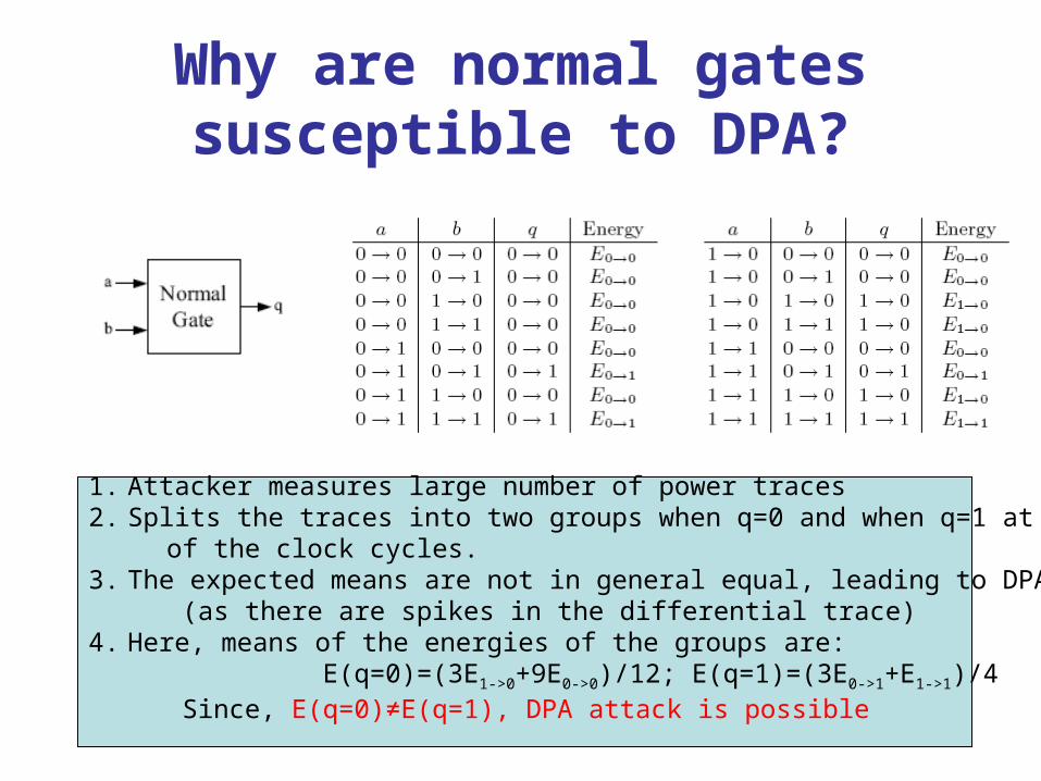
Why are normal gates susceptible to DPA?
1. Attacker measures large number of power traces2. Splits the traces into two groups when q=0 and when q=1 at the end of the clock cycles.3. The expected means are not in general equal, leading to DPA attacks (as there are spikes in the differential trace)4. Here, means of the energies of the groups are: E(q=0)=(3E1->0+9E0->0)/12; E(q=1)=(3E0->1+E1->1)/4 Since, E(q=0)≠E(q=1), DPA attack is possible
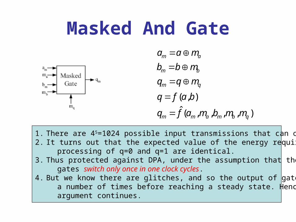
Masked And Gate
( , )
ˆ ( , , , , )
m a
m b
m q
m m a m b q
a a m
b b m
q q m
q f a b
q f a m b m m
1. There are 45=1024 possible input transmissions that can occur.2. It turns out that the expected value of the energy required for the processing of q=0 and q=1 are identical. 3. Thus protected against DPA, under the assumption that the CMOS gates switch only once in one clock cycles.4. But we know there are glitches, and so the output of gates swing a number of times before reaching a steady state. Hence... the argument continues.
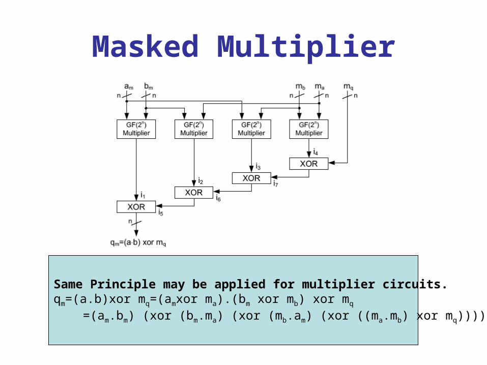
Masked Multiplier
Same Principle may be applied for multiplier circuits. qm=(a.b)xor mq=(amxor ma).(bm xor mb) xor mq
=(am.bm) (xor (bm.ma) (xor (mb.am) (xor ((ma.mb) xor mq))))
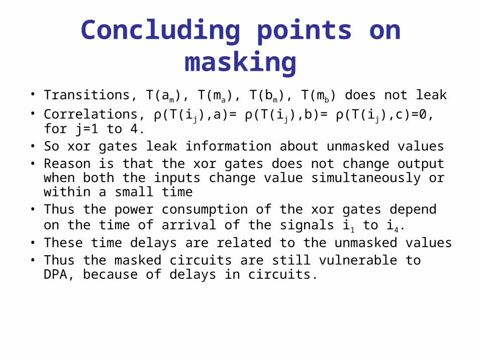
Concluding points on masking
• Transitions, T(am), T(ma), T(bm), T(mb) does not leak• Correlations, ρ(T(ij),a)= ρ(T(ij),b)= ρ(T(ij),c)=0, for j=1 to
4.• So xor gates leak information about unmasked values• Reason is that the xor gates does not change output
when both the inputs change value simultaneously or within a small time
• Thus the power consumption of the xor gates depend on the time of arrival of the signals i1 to i4.
• These time delays are related to the unmasked values• Thus the masked circuits are still vulnerable to DPA,
because of delays in circuits.
Outline of the Talk
• What is meant by Side Channel Attacks?
• Power Based Side Channel Analysis
• DFT in Cryptographic Algorithms and Scan Chain Based Attacks
DFT of
Cryptographic Hardware&
Scan Based Attacks

Motivation Behind the Work
• VLSI of Cryptosystems have become popular
• High complexity raises questions about reliability
• Scan Chain Based testing is powerful and popular method
• Double Edged Sword: Opens up side-channels for cryptanalysis!!

What is a Scan Chain ?
Combinational Circuit
MuxD
clk
Q
MuxD
clk
Q
Test_seScan_out
Scan_in

Overview of contemporary research
• Yang, Wu, Karri, “Scan Chain Based Side Channel Attack on dedicated hardware implementations of Data Encryption Standard”, ITC Oct 2004 : ATTACKED A BLOCK CIPHER
• D. Mukhopadhyay, S. Banerjee, D. RoyChowdhury, and B. Bhattacharya, “Cryptoscan: Secured Scan Chain Architecture”, 14th IEEE Asian Test Symposium 2005: ATTACKED A STREAM CIPHER
• Emphasizes the need for new type of scan chains…• Idea:
– Increased controllability and observability for the authorized user
– Reduced controllability and observability for the unauthorized user
– Not Trivial

Scan Based Attacks!!!- Attack on AES (Presented in DAC’05) --Attack on Stream Cipher (Presented
in ATS’05)

Step 1: Determine scan chain structure
• Input is partitioned into 16 bytes a11,… a14, a21,… a24, a31,… a34, a41,… a44
• Register R is fed back to point b ten times with RK1 to RK10
• 128-bit Round register R is in scan chains
• The complexity of AES is reduced to one round
• Can we determine RK0?
KeyXorRK0Input
Sbox
ShiftRow
MixColumn
RK1
a
b
c
d
e
fRegister R
KeyXor
…..Yang, Wu and Karri, “Secure Scan: A Design for Test Architecture for Crypto-chips”, DAC 2005…

KeyXorRK0Input
Sbox
ShiftRow
MixColumn
RK1
a
b
c
d
e
fRegister R
KeyXor
Step 1: Determine scan chain structure
• The locations of flip-flops of R in the scan chains are unknown
• Change in a11 change in b11 change in c11 change in d10 change in ei0 change in fi0 4 byte at R
• On average, 15 patterns are enough applied at a11 to determine all the 32-bit in Register R (fi0) by comparing the scanned out bit streams
…..Yang, Wu and Karri, “Secure Scan: A Design for Test Architecture for Crypto-chips”, DAC 2005…
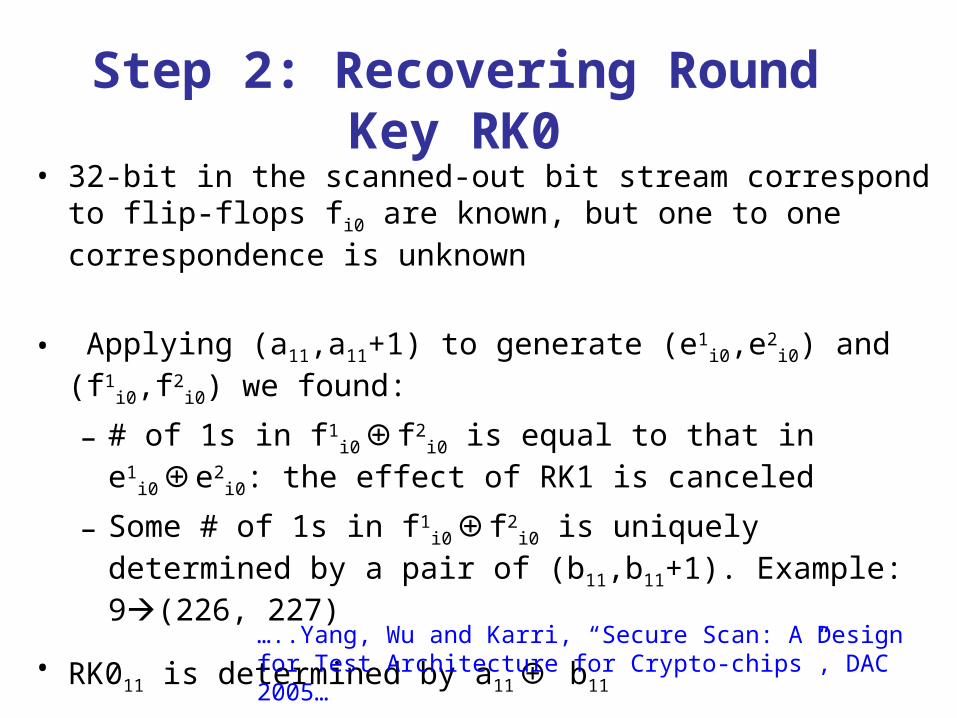
Step 2: Recovering Round Key RK0
• 32-bit in the scanned-out bit stream correspond to flip-flops fi0 are known, but one to one correspondence is unknown
• Applying (a11,a11+1) to generate (e1i0,e2
i0) and (f1i0,f2
i0) we found:
– # of 1s in f1i0⊕f2
i0 is equal to that in e1i0⊕e2
i0: the effect of RK1 is canceled
– Some # of 1s in f1i0⊕f2
i0 is uniquely determined by a pair of (b11,b11+1). Example: 9(226, 227)
• RK011 is determined by a11⊕ b11 …..Yang, Wu and Karri, “Secure Scan: A Design for Test Architecture for Crypto-chips”, DAC 2005…

Classical Structure of Stream Cipher
Boolean Function
(Message Bits)
Key Stream
D. Mukhopadhyay, S. Banerjee, D. RoyChowdhury and B. Bhattacharya, “CryptoScan: Secured Scan Chain Architecture”, ATS 2005
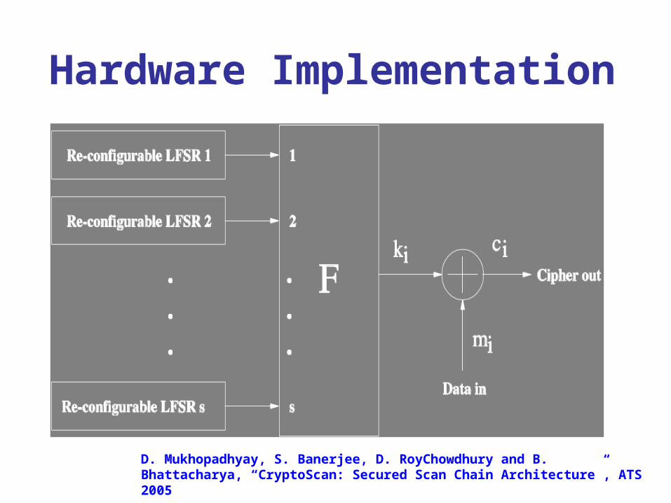
Hardware Implementation
D. Mukhopadhyay, S. Banerjee, D. RoyChowdhury and B. Bhattacharya, “CryptoScan: Secured Scan Chain Architecture”, ATS 2005

Re-configurable LFSR
Configurable
Register
Shift
Register
Programs the feedback polynomial

Attacking the Stream Cipher Using Scan Chains
• Objective of the attacker: To obtain the message stream (m1 , m2 ,…, ml) from the stream of ciphertexts (c1 , c2 ,…, cl)
• Three Stage Attack– Ascertain the Structure of the seed– Ascertain the positions of the registers– Deciphers the cryptogram
D. Mukhopadhyay, S. Banerjee, D. RoyChowdhury and B. Bhattacharya, “CryptoScan: Secured Scan Chain Architecture”, ATS 2005

Attacking Environment
n: size of CR and SR
w: size of the seed
s: number of LFSRs
D. Mukhopadhyay, S. Banerjee, D. RoyChowdhury and B. Bhattacharya, “CryptoScan: Secured Scan Chain Architecture”, ATS 2005
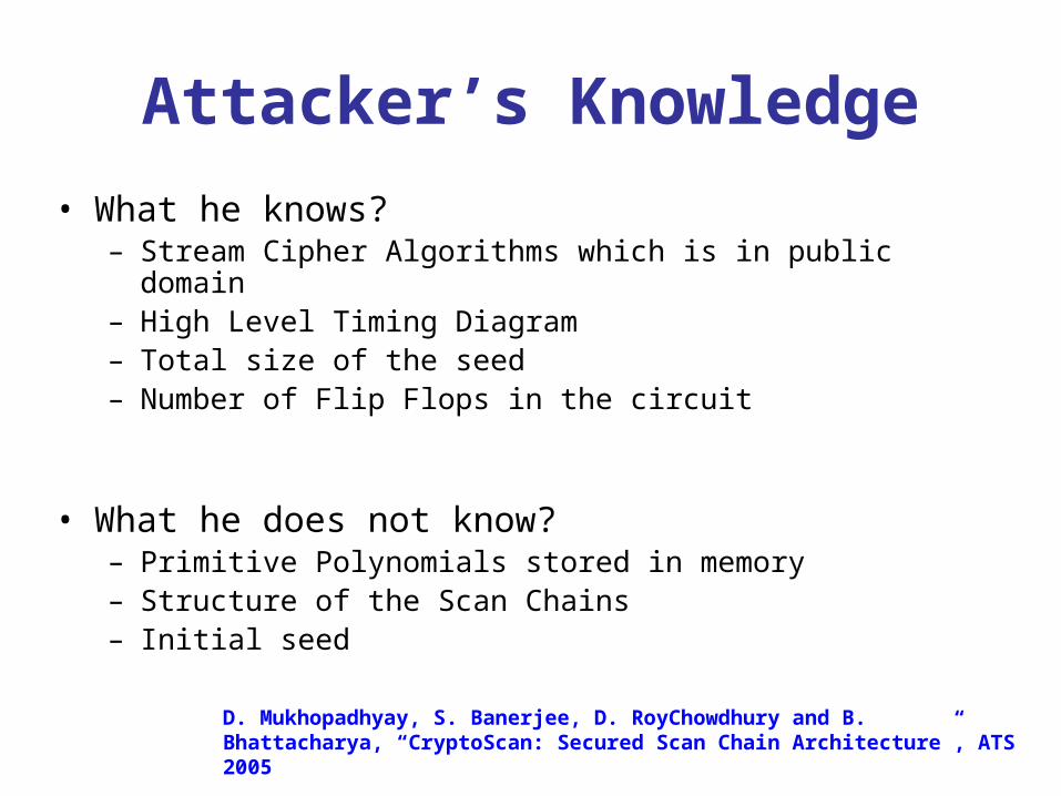
Attacker’s Knowledge
• What he knows?– Stream Cipher Algorithms which is in public domain– High Level Timing Diagram– Total size of the seed – Number of Flip Flops in the circuit
• What he does not know?– Primitive Polynomials stored in memory– Structure of the Scan Chains – Initial seed
D. Mukhopadhyay, S. Banerjee, D. RoyChowdhury and B. Bhattacharya, “CryptoScan: Secured Scan Chain Architecture”, ATS 2005
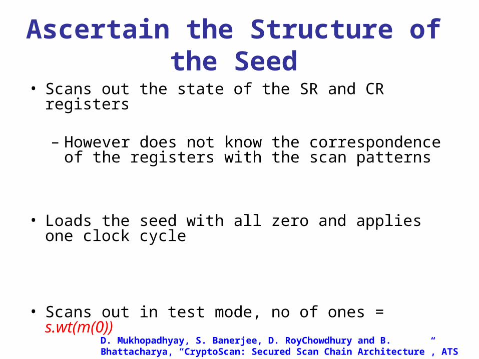
Ascertain the Structure of the Seed
• Scans out the state of the SR and CR registers
– However does not know the correspondence of the registers with the scan patterns
• Loads the seed with all zero and applies one clock cycle
• Scans out in test mode, no of ones = s.wt(m(0))D. Mukhopadhyay, S. Banerjee, D. RoyChowdhury and B. Bhattacharya, “CryptoScan: Secured Scan Chain Architecture”, ATS 2005

Ascertain the Structure of the Seed….
• Next, the attacker sets the first bit of seed to 1 and the rest to 0 and apply one clock cycle
• The bit with value 1 can go either to the memory or to the SRs
• Scan out the data in test mode.
• If the bit goes to the SR, no of ones = s.wt(m(0))+1 else no of ones = s.wt(m(p))• Repeat the same for all the w bits of the seed
Not Equal
(as s > 1)
D. Mukhopadhyay, S. Banerjee, D. RoyChowdhury and B. Bhattacharya, “CryptoScan: Secured Scan Chain Architecture”, ATS 2005

Thus the attacker has ascertained the following….
• The number of bits (w1) in the seed and their positions in the seed which are used to address the memory. Thus, the attacker also knows the bits in the seed which are used to initialize the SRs
• The attacker also identifies the positions of the CR resisters in the scan chains. He also identifies the positions of the SR resisters in the scan out data, however the order is not known
• Complexity : O(wns)
D. Mukhopadhyay, S. Banerjee, D. RoyChowdhury and B. Bhattacharya, “CryptoScan: Secured Scan Chain Architecture”, ATS 2005
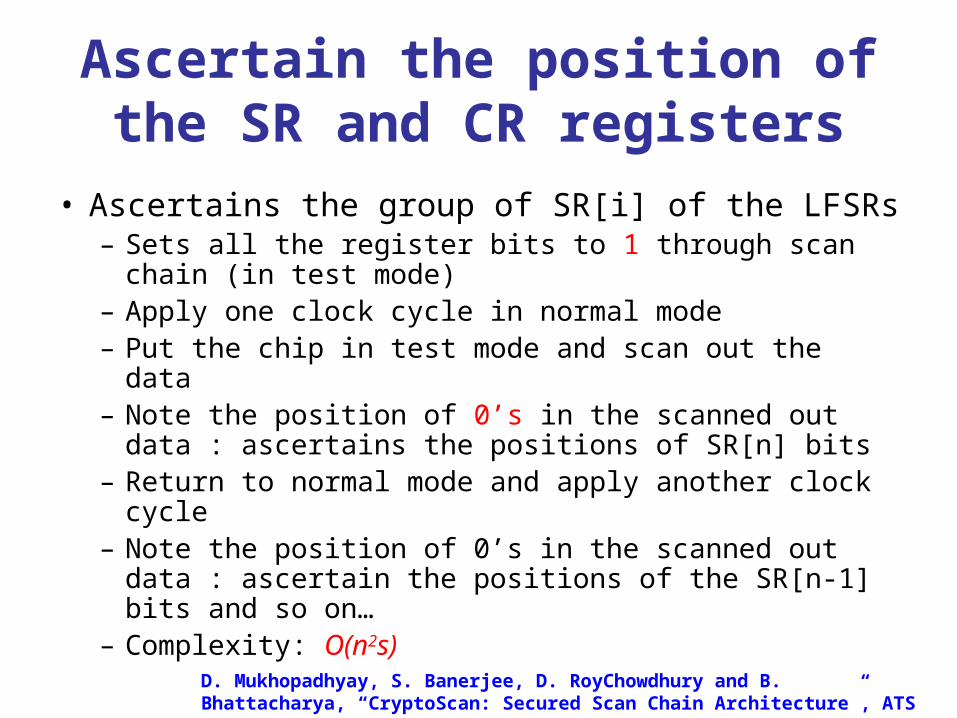
Ascertain the position of the SR and CR registers
• Ascertains the group of SR[i] of the LFSRs– Sets all the register bits to 1 through scan chain (in
test mode)– Apply one clock cycle in normal mode – Put the chip in test mode and scan out the data– Note the position of 0’s in the scanned out data :
ascertains the positions of SR[n] bits– Return to normal mode and apply another clock cycle – Note the position of 0’s in the scanned out data :
ascertain the positions of the SR[n-1] bits and so on…– Complexity: O(n2s)
D. Mukhopadhyay, S. Banerjee, D. RoyChowdhury and B. Bhattacharya, “CryptoScan: Secured Scan Chain Architecture”, ATS 2005
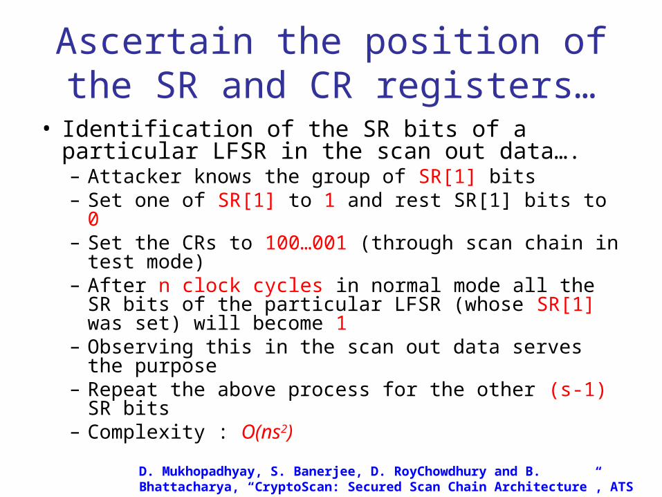
Ascertain the position of the SR and CR registers…
• Identification of the SR bits of a particular LFSR in the scan out data….– Attacker knows the group of SR[1] bits– Set one of SR[1] to 1 and rest SR[1] bits to 0– Set the CRs to 100…001 (through scan chain in test
mode)– After n clock cycles in normal mode all the SR bits of
the particular LFSR (whose SR[1] was set) will become 1
– Observing this in the scan out data serves the purpose
– Repeat the above process for the other (s-1) SR bits– Complexity : O(ns2)
D. Mukhopadhyay, S. Banerjee, D. RoyChowdhury and B. Bhattacharya, “CryptoScan: Secured Scan Chain Architecture”, ATS 2005

Deciphering the Cryptogram
• Decoding cl : The attacker knows the values of the SR registers of all the LFSRs: {SR[n],SR[n-1],……SR[2],SR[1]}
– The previous state of the LFSRs can be computed as: {SR[n-1],SR[n-2],…,SR[1],SR[n] SR[1]} (as CR[1] is always 1)
– He sets the message bit of the device to zero and the device in normal mode. One clock cycle is applied and the output is observed. The output is the value of kl. Thus ml = cl kl
D. Mukhopadhyay, S. Banerjee, D. RoyChowdhury and B. Bhattacharya, “CryptoScan: Secured Scan Chain Architecture”, ATS 2005

Deciphering the cryptogram…
• Decoding c1,c2,….,cl-1: For decoding cl-1, similarly the attacker computes the previous stage of the SR register of all the LFSRs. Continuing the step for l times leads to the decoding of the entire cryptogram. Thus, the time complexity is O(nsl)
D. Mukhopadhyay, S. Banerjee, D. RoyChowdhury and B. Bhattacharya, “CryptoScan: Secured Scan Chain Architecture”, ATS 2005

Coming back to …Why Non-trivial???
• Scrambling Technique (Dynamic Re-ordering of scan chains)– Separate test key to program the inter-
connections– Wiring complexity increases fast with the
number of flops– Control circuit uses themselves flip-flops– Statistical Analysis may reveal the ordering
Who tests them ?

Lock and Key Technique
• Test Key• Test Security Controller (TSC): compares the
key• If wrong key is entered, design goes to an
insecured mode unless reset• Demerits:
– Large Area Overhead– TSC uses flip-flops…– Use of additional key, overhead on key exchange

Observations…
• Any Flip-flops related to secret lead to attacks
• Use of additional key not desirable
• Area Overhead should be less
• On-line testing should be possible
Non-trivial….

Secure Scan : Karri’s Curry• Test and debug crypto chips using general scan
based DFT– Information obtained from scan chains should not be
useful in retrieving the secret key
• Two copies of the secret key – Secure key: hardwired or in secure memory– Mirror Key (MKR): used for testing
• Two modes of operation: Insecure and Secure– Insecure mode: secure key is isolated, MKR is used and
debug allowed– Secure mode: secure key is used and debug disabled

Secure Scan ArchitectureTDI
Test Controller
Crypto Core
Scan_mode MKR
...
...
LogicKEY
Enable_Scan_In
Enable_Scan_Out
Load_Key
TMS
TCK
TDO
• Insecure Mode– Enable_Scan_In=1, Enable_Scan_Out=1, Load_Key=0
• Secure Mode– Enable_Scan_In=0, Enable_Scan_Out=0, Load_Key=1
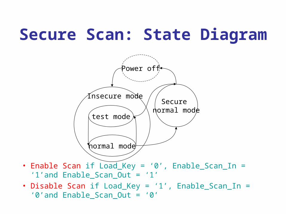
Secure Scan: State Diagram
• Enable Scan if Load_Key = ‘0’, Enable_Scan_In = ‘1’and Enable_Scan_Out = ‘1’
• Disable Scan if Load_Key = ‘1’, Enable_Scan_In = ‘0’and Enable_Scan_Out = ‘0’
test mode
normal mode
Secure normal mode
Insecure mode
Power off
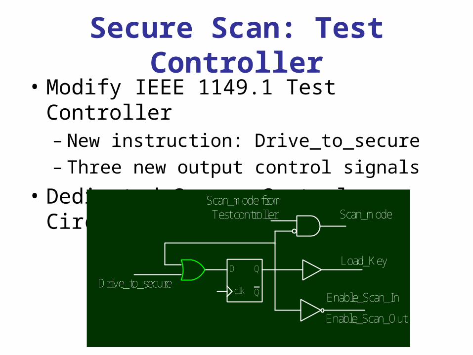
Secure Scan: Test Controller• Modify IEEE 1149.1 Test Controller
– New instruction: Drive_to_secure – Three new output control signals
• Dedicated Secure Control Circuit
D Q
QclkDrive_to_secure
Load_Key
Enable_Scan_Out
Scan_mode from Test controller Scan_mode
Enable_Scan_In

Overhead Analysis
ArchitectureArea
(gates)
Area overhead
(gates)Ratio
Iterative (with KS)
31,234 412 1.32%
Iterative (without KS)
30,854 412 1.34%
Pipelined (with KS)
273,187 412 0.15%
Pipelined (without KS)
282,120 4620 1.64%

Analysis of Secure Scan • Merits:
– Does not degrade test speed– Circuit incurred by secure scan is easy to test– Easy to integrate into current scan DFT flow
• Specify MKRs to corresponding secret key bit and do secure synthesis (Secured CAD??)
– Area overhead is very small• Demerits:
– If secret is permanently stored like credit card nos.– On-line testing not possible– If device is part of a critical system it should remain on
continuously– Testing of MKR not straight-forward– In-convenient if the AES engine is used in a Cipher Block
Chaining Mode

Design of Crypto-Scan
• Hardware Designs of Ciphers are insecure with conventional scan chains
• Require Scan Chains for cryptographic chips!• Objectives:
– Modify the Scan Structure so that testing features are maintained
– The Scan Structure does not open up a
side-channel

Scan Tree Architecture
FF1 FF2 FF3 FF4 FF5 FF6
Scan In
Scan Out
t1 1 0 X 0 0 1
t2 0 0 1 X 1 X
t3 X 1 0 0 X X

Scan Tree Architecture…
FF1FF2
FF4FF5
FF3FF6
FF1
FF6
FF2
FF3
FF4FF5
{FF2}, {FF1, FF6}, {FF3, FF4, FF5}
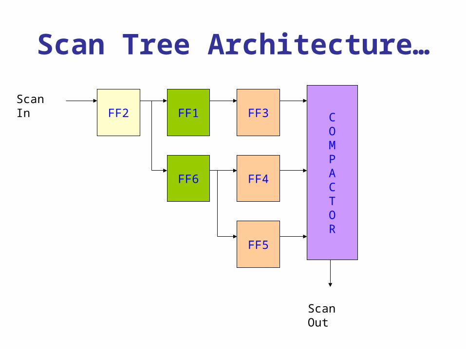
Scan Tree Architecture…
FF1FF2 FF3
FF4
FF5
FF6
MISR
Scan In
Scan Out
COMPACTOR
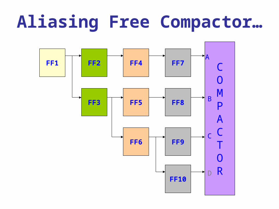
Aliasing Free Compactor…
FF2FF1 FF4
FF5
FF6
FF3
COMPACTOR
FF7
FF8
FF9
FF10
A
B
C
D

Expected Responses…
Test Responses
Test
Patterns
FF1 FF2 FF3 FF4 FF5 FF6 FF7 FF8 FF9 FF10
t1
t2
t3
t4
1 0 1 1 0 1 1 1 0 0
0 1 0 0 1 1 0 1 1 0
1 0 0 0 1 1 1 1 0 0
0 0 1 1 1 0 0 1 0 1

Truth Table for CompactorCounter-1 (T) Counter-1 (C) Inputs Outputs
t1 t2 c1 c2 A B C D Y Decision
0 0
0 0
0 0
0 0
0 0
0 0
0 0
0 0
0 0
… ...
0 0
0 0
0 0
0 0
0 0
0 1
0 1
0 1
0 1
… …
1 1 0 0
0 X X X
X 0 X X
X X 1 X
X X X 1
1 0 1 X
0 X X X
X 1 X X
X X 0 X
… …..
0
1
1
1
1
1
0
0
0
…..
Fault Free
Faulty
Faulty
Faulty
Faulty
Fault Free
Faulty
Faulty
Faulty
…..

Why is Crypto-Scan Secured?
• d: Compatible Groups
• L= {l1,l2,…..,ld}
• N : Total Number of flip-flops
• Scan-Tree Characterized: st(l,d)
• Normal Scan Chain :– N Known– Position of flip-flops can be ascertained

Security of Crypto-Scan
• Crypto-Scan: – d does not reveal information about N
– d≤N≤dld
– Compactor hides the value of ld, hence N
cannot be determined
– Scan Structure secured because value of L is hidden
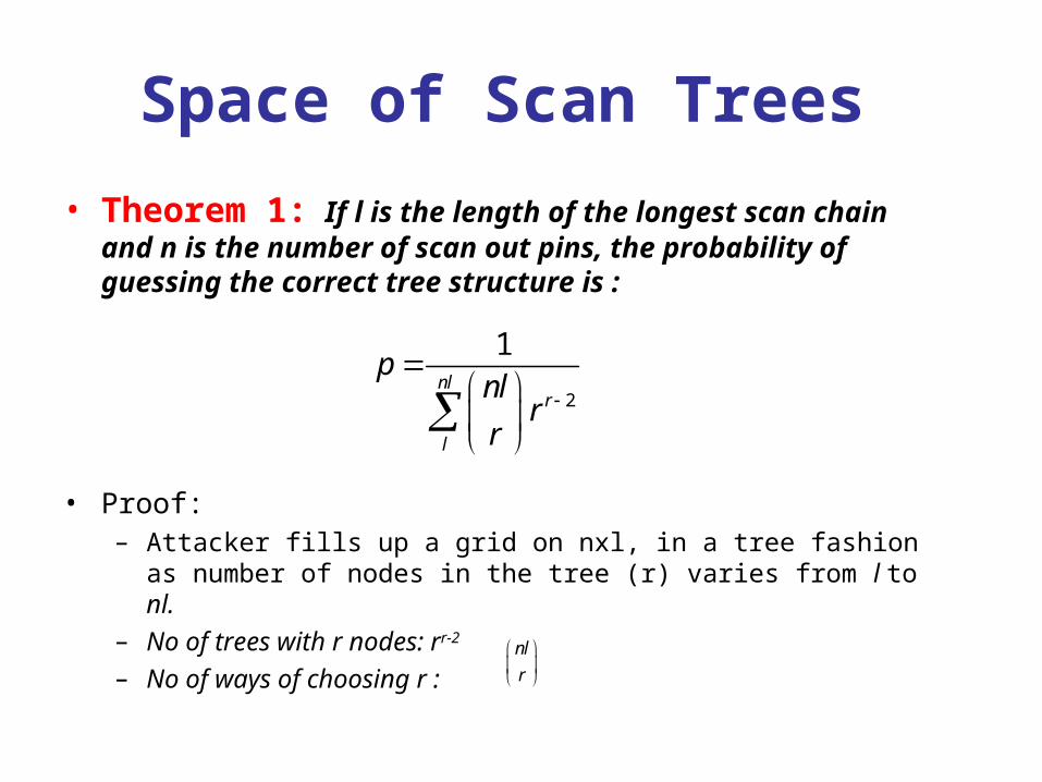
Space of Scan Trees
• Theorem 1: If l is the length of the longest scan chain and n is the number of scan out pins, the probability of guessing the correct tree structure is :
• Proof: – Attacker fills up a grid on nxl, in a tree fashion as number of nodes
in the tree (r) varies from l to nl.
– No of trees with r nodes: rr-2
– No of ways of choosing r :
2
1nl
r
l
pnlr
r
nl
r

Experimental Setup
• ISCAS’89 Bench Marks
• Solaris-10 Platform
• Synthesized using Design Compiler (Synopsys)
• TetraMax (Synopsys) is used for test pattern generation

Area Overhead Due to Compactor and Scan Tree
Benchmark
Circuits Name
Area Overhead
% s298
s344
s382
s400
s5378
s9234
s13202
s15850
s35932
s38417
21
18
19
19.4
17
17.7
16.4
17
15.8
16.4

Analysis
• Merits:– Fast on-line testing : test compression – Testing of components easy– No use of flip-flops
• Demerits:– Overhead?
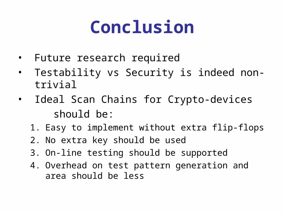
Conclusion
• Future research required• Testability vs Security is indeed non-trivial• Ideal Scan Chains for Crypto-devices
should be:1. Easy to implement without extra flip-flops
2. No extra key should be used
3. On-line testing should be supported
4. Overhead on test pattern generation and area should be less
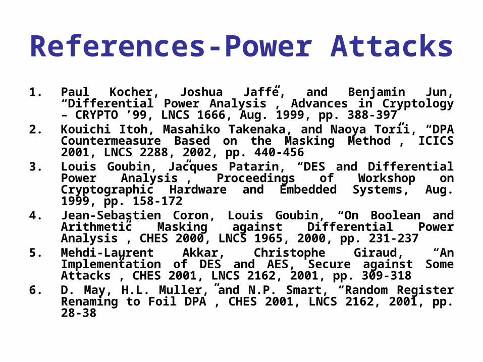
References-Power Attacks1. Paul Kocher, Joshua Jaffe, and Benjamin Jun, “Differential Power
Analysis”, Advances in Cryptology – CRYPTO ’99, LNCS 1666, Aug. 1999, pp. 388-397
2. Kouichi Itoh, Masahiko Takenaka, and Naoya Torii, “DPA Countermeasure Based on the Masking Method”, ICICS 2001, LNCS 2288, 2002, pp. 440-456
3. Louis Goubin, Jacques Patarin, “DES and Differential Power Analysis”, Proceedings of Workshop on Cryptographic Hardware and Embedded Systems, Aug. 1999, pp. 158-172
4. Jean-Sebastien Coron, Louis Goubin, “On Boolean and Arithmetic Masking against Differential Power Analysis”, CHES 2000, LNCS 1965, 2000, pp. 231-237
5. Mehdi-Laurent Akkar, Christophe Giraud, “An Implementation of DES and AES, Secure against Some Attacks”, CHES 2001, LNCS 2162, 2001, pp. 309-318
6. D. May, H.L. Muller, and N.P. Smart, “Random Register Renaming to Foil DPA”, CHES 2001, LNCS 2162, 2001, pp. 28-38

References-Power Attacks7. S. Almanei, “Protecting Smart Cards from Power Analysis Attacks”,
http://islab.oregonstate.edu/koc/ece679cahd/s2002/almanei.pdf, May. 2002
8. Adi Shamir, “Protecting Smart Cards from Passive Power Analysis with Detached Power Supplies”, CHES 2000, LNCS 1965, 2000, pp. 71-77
9. P. Y. Liardet, N. P. Smart, “Preventing SPA/DPA in ECC Systems Using the Jacobi Form”, CHES 2001, LNCS 2162, 2001, pp. 391-401
10. Marc Joye, Christophe Tymen, “Protections against Differential Analysis for Elliptic Curve Cryptography”, CHES 2001, LNCS 2162, 2001, pp. 377-390
11. Stefan Mangard, Kai Schramm: Pinpointing the Side-Channel Leakage of Masked AES Hardware Implementations. CHES 2006: 76-90
12. Stefan Mangard, Thomas Popp, Berndt M. Gammel: Side-Channel Leakage of Masked CMOS Gates. CT-RSA 2005: 351-365
13. Elisabeth Oswald, Stefan Mangard, Norbert Pramstaller, Vincent Rijmen: A Side-Channel Analysis Resistant Description of the AES S-Box. FSE 2005: 413-423
References Scan Chain Attacks
1. Bo Yang, Kaijie Wu and R. Karri, Scan Based Channel Attack on Dedicated Hardware Implementation of Data Encryption Standard, Proceedings of International COnference (ITC), 26-28 Oct 2004, pp. 334-344.
2. R.Kapoor, Security vs. Test quality: Are They Mutually Exclusive?, Proceedings of International Test Conference (ITC), 26-28 Oct 2004, pp. 1413.
3. D. Hely, M. Flottes, F. Bancel, B. Rouzeyre, N. Berard, M. Renovell, 4. Scan Design and Secure Chip, Proceedings of $10^{th}$ IEEE
International On-Line Testing Symposium (IOLTS), 12-14 July 2004, pp. 219 - 226.
5. Bo Yang, Kaijie Wu and R. Karri, Secure scan:A Design-for-test Architecture for Crypto-chips, Proceedings of 42nd Design Automation Conference (DAC), 2005, pp. 135-140.
6. Bo Yang, Kaijie Wu and R. Karri, {\em Secure scan:A Design-for-test Architecture for Crypto-chips, IEEE Transactions on Computer Aided-Design of Integrated Circuits and Systems, vol 25, no 10, October 2006, pp. 2287-2293.

References Scan Chain Attacks
7. J. Lee, M. Tehranipoor, C. Patel, J. Plusquellic, Securing Scan Design Using Lock and Key Technique, Proceedings of 20th IEEE International Symposium on Defect and Fault Tolerance in VLSI Systems, (DFT), 2005, pp. 51-62.
8. D. Mukhopadhyay, S. Banerjee, D. RoyChowdhury, and B. Bhattacharya, Cryptoscan: Secured Scan Chain Architecture, Proceedings of 14th IEEE Asian Test Symposium, (ATS), 2005, pp. 348-353.
9. P. Kitsos, G. Kostopoulos, N. Sklavos, and O. Koufopavlou, Hardware Implementation of the RC4 Stream Cipher, Proceedings of 46th IEEE Midwest Symposium on Circuits and Systems, December 27-30, Cairo, Egypt, 2003, vol. 3, pp. 1363-1366.


![Back end[1] debdeep](https://img.pdfslide.us/doc/110x75/55680229d8b42a242a8b487f/back-end1-debdeep.jpg)