Embed Size (px)
Citation preview
Instructions for UseEdition USA
SI-1010 / SI-1015 / SI-1023
2
Contents
Symbols .......................................................................................................................................................................................................... 41. Introduction ............................................................................................................................................................................................... 82. Electromagnetic compatibility (EMC) ................................................................................................................................................... 103. Unpacking ................................................................................................................................................................................................ 114. Scope of delivery ......................................................................................................................................................................................125. Safety notes .............................................................................................................................................................................................136. Description............................................................................................................................................................................................... 20
of front panel ....................................................................................................................................................................................... 20of rear panel .........................................................................................................................................................................................21of foot control S-N2/S-NW .................................................................................................................................................................. 22of motor with cable ............................................................................................................................................................................. 24
7. Start-up ..................................................................................................................................................................................................... 258. Control unit .............................................................................................................................................................................................. 269. Starting operation ................................................................................................................................................................................... 2710. Control unit operation ........................................................................................................................................................................... 28
Main menu ........................................................................................................................................................................................... 28Menue Navigation ............................................................................................................................................................................... 31Factory settings .................................................................................................................................................................................. 36Documentation with USB stick ........................................................................................................................................................... 42ioDent® platform ................................................................................................................................................................................. 44Beacon ................................................................................................................................................................................................ 46
11. Error messages ...................................................................................................................................................................................... 47
3
Contents
12. Hygiene and maintenance.................................................................................................................................................................... 50General notes ...................................................................................................................................................................................... 50Limitations on processing .................................................................................................................................................................. 51Initial treatment at the point of use .................................................................................................................................................. 52Manual cleaning .................................................................................................................................................................................. 53Manual disinfection ............................................................................................................................................................................ 54Automated cleaning and disinfection ............................................................................................................................................... 55Drying .................................................................................................................................................................................................. 56Inspection, maintenance and testing ............................................................................................................................................... 57Packaging ............................................................................................................................................................................................ 58Sterilization ......................................................................................................................................................................................... 59Storage .................................................................................................................................................................................................61
13. Servicing ................................................................................................................................................................................................ 6214. W&H accessories and spare parts....................................................................................................................................................... 6415. Technical data ........................................................................................................................................................................................ 6716. Disposal ................................................................................................................................................................................................. 69W&H course certificate ............................................................................................................................................................................... 70Explanation of warranty terms ................................................................................................................................................................... 73Authorized W&H service partners ...............................................................................................................................................................74Manufacturer’s declaration......................................................................................................................................................................... 75
4
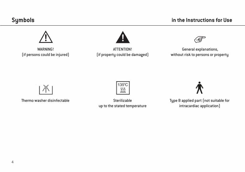
Symbols
WARNING!(if persons could be injured)
ATTENTION!(if property could be damaged)
General explanations, without risk to persons or property
in the Instructions for Use
Sterilizable up to the stated temperature
Thermo washer disinfectable Type B applied part (not suitable for intracardiac application)
5
Symbols
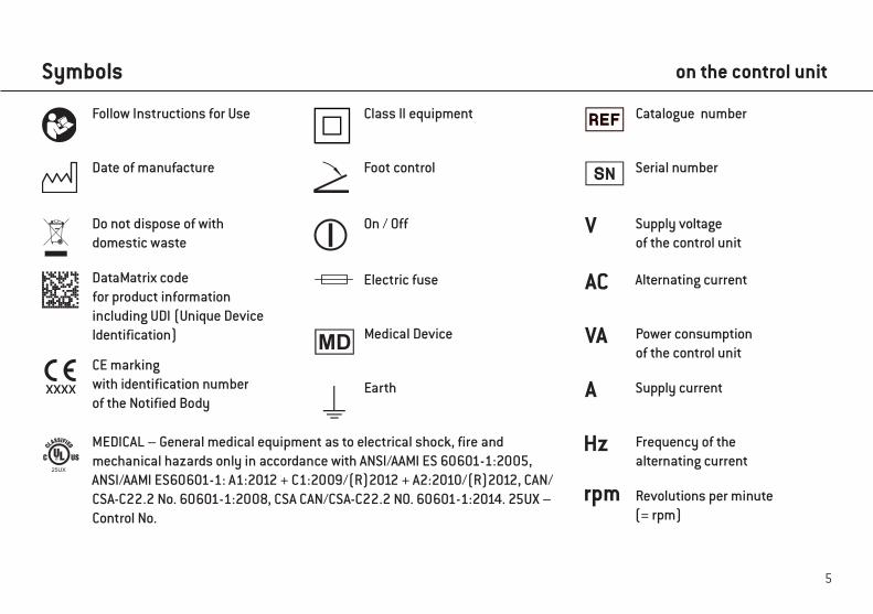
Follow Instructions for Use Class II equipment
Date of manufacture
Catalogue number
Serial number
Revolutions per minute (= rpm)
Alternating current
Power consumption of the control unit
Electric fuse
Supply voltage of the control unit
Supply current
Frequency of the alternating current
DataMatrix code for product information including UDI (Unique Device Identification)
Foot control
Do not dispose of withdomestic waste
On / Off
MEDICAL – General medical equipment as to electrical shock, fire and mechanical hazards only in accordance with ANSI/AAMI ES 60601-1:2005, ANSI/AAMI ES60601-1: A1:2012 + C1:2009/(R)2012 + A2:2010/(R)2012, CAN/CSA-C22.2 No. 60601-1:2008, CSA CAN/CSA-C22.2 NO. 60601-1:2014. 25UX – Control No.
CE marking with identification number of the Notified Body
XXXX
on the control unit
Earth
25UX
Medical Device
6
Symbols
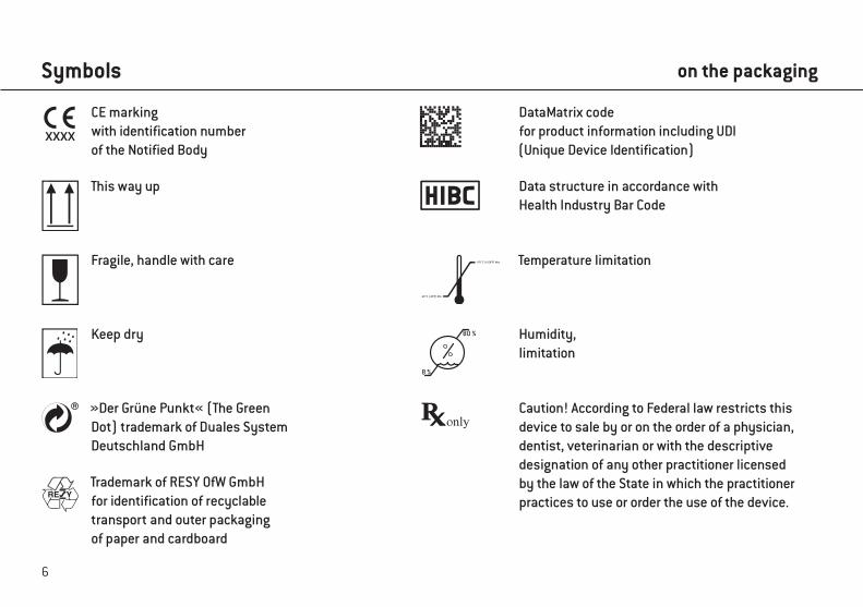
This way up
Caution! According to Federal law restricts this device to sale by or on the order of a physician, dentist, veterinarian or with the descriptive designation of any other practitioner licensed by the law of the State in which the practitioner practices to use or order the use of the device.
Fragile, handle with care
Keep dry
Temperature limitation
Humidity, limitation
»Der Grüne Punkt« (The Green Dot) trademark of Duales System Deutschland GmbH
Trademark of RESY OfW GmbH for identification of recyclable transport and outer packaging of paper and cardboard
-40 °C (-40°F) Min.
+70 °C (+158°F) Max.
8 %
80 %
CE marking with identification number of the Notified Body
XXXX
Data structure in accordance with Health Industry Bar Code
DataMatrix code for product information including UDI (Unique Device Identification)
on the packaging
7
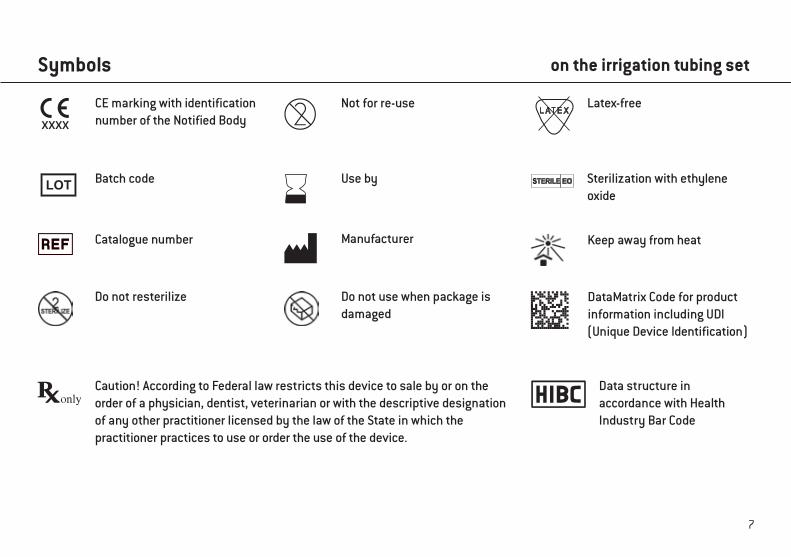
Symbols on the irrigation tubing set
Sterilization with ethyleneoxide
Caution! According to Federal law restricts this device to sale by or on the order of a physician, dentist, veterinarian or with the descriptive designation of any other practitioner licensed by the law of the State in which the practitioner practices to use or order the use of the device.
Batch code
Not for re-use Latex-free
Use by
CE marking with identification number of the Notified Body XXXX
Catalogue number Manufacturer
Do not resterilize Do not use when package isdamaged
Keep away from heat
Data structure in accordance with Health Industry Bar Code
DataMatrix Code for product information including UDI (Unique Device Identification)
8
1. Introduction
For your safety and the safety of your patientsThese Instructions for Use explain how to use your product. However, we must also warn against possible hazardous situations.Your safety, the safety of your team and, of course, the safety of your patients, are of paramount importance to us.
Observe the safety notes.
Intended useMechanical drive unit with coolant supply for transmission instruments with ISO 3964 (DIN 13940) compatible coupling system, foruse in dental surgery, implantology and maxillofacial surgery (CMF) for treatment of dental hard tissue.
Misuse may damage the medical device and hence cause risks and hazards for patients, users and third parties.
Qualifications of the userOnly suitably qualified medical, technical and specialist trained staff may use the medical device.We have based our developmed and design of the medical device on the »physician« target group.
9
Introduction
Production according to EU DirectiveThe medical device complies with the regulations of Directive 93/42/EEC.
Responsibility of the manufacturerThe manufacturer can only accept responsibility for the safety, reliability and performance of the medical device when compliance with the following instructions is ensured:
> The medical device must be used in accordance with these Instructions for Use. > The medical device has no components that can be repaired by the user. > Modifications or repairs must only be undertaken by an authorized W&H service partner (see page 74). > The electrical installation at the premises must comply with the regulations laid out in IEC 60364-7-710 (“Installation of
electrical equipment in rooms used for medical purposes”) or with the regulations applicable in your country. > Unauthorized opening of the control unit invalidates all claims under warranty and any other claims.
In addition to unauthorized assembly, installation, modification of or repairs to the control unit, motor with cable, transmission instrument and non-compliance with our instructions, improper use will void the warranty and release us from all other claims.
Any serious incident that has occurred in relation to the medical device should be reported to the manufacturer and the competent authority!
10
2. Electromagnetic compatibility (EMC)
Medical electrical device is subject to particular precautions with regards to EMC and must be installed and put into operation in accordance with the EMC notes included.
W&H only guarantees compliance of the device with the EMC Directives when it is used with original W&H accessories and spare parts. The use of accessories and spare parts that have not been approved by W&H may lead to increased emission of electromagnetic interference or to reduced resistance to electromagnetic interference.
HF communication equipmentPortable HF communications equipment (including peripherals such as antenna cables and external antennas) should be used no closer than 30 cm (12 inches) to the medical device. Otherwise, degradation of the performance of this medical device could result.
The medical device may be interfered by other equipment, even if these other devices comply with CISPR (International special committee on radio interference) emission requirements.
Use of this medical device adjacent to or stacked with other equipment should be avoided because it could result in improper operation. If such use is necessary, this medical device and the other equipment should be observed to verify that they are operating normally.
The medical device is not intended for use in the vicinity of HF surgical devices.
11
3. Unpacking
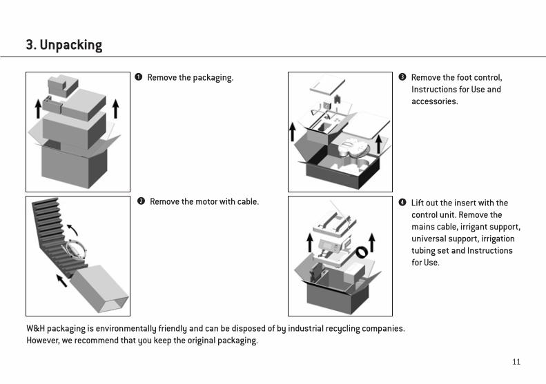
Remove the packaging.
Remove the motor with cable.
Remove the foot control, Instructions for Use and accessories.
Lift out the insert with the control unit. Remove the mains cable, irrigant support, universal support, irrigation tubing set and Instructions for Use.
W&H packaging is environmentally friendly and can be disposed of by industrial recycling companies.However, we recommend that you keep the original packaging.
12
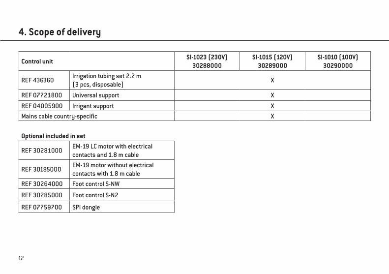
4. Scope of delivery
Control unitSI-1023 (230V)
30288000SI-1015 (120V)
30289000SI-1010 (100V)
30290000
REF 436360Irrigation tubing set 2.2 m (3 pcs, disposable)
X
REF 07721800 Universal support X
REF 04005900 Irrigant support X
Mains cable country-specific X
Optional included in set
REF 30281000EM-19 LC motor with electrical contacts and 1.8 m cable
REF 30185000EM-19 motor without electrical contacts with 1.8 m cable
REF 30264000 Foot control S-NW
REF 30285000 Foot control S-N2
REF 07759700 SPI dongle
13
5. Safety notes
> Before using the medical device for the first time, store it at room temperature for 24 hours > Check the medical device and the motor with cable for damage and loose parts every time before use. > Do not operate the medical device and the motor with cable if it is damaged. > Check the parameter settings every time the device is restarted. > Perform a test run prior to every treatment. > The responsibility for the use and timely shutdown of the system lies with the user. > Ensure that it is possible to complete the operation safely should the units or instruments fail.
The medical device is not approved for operation in potentially explosive atmospheres.
Do not twist or kink the motor cable! Do not coil it too tightly!Moisture in the motor with cable may cause a malfunction! (Risk of short circuit)
Control unit / Motor
14
Safety notes
> Use only original W&H fuses. > Never touch the patient and the electrical connections on the control unit simultaneously. > Make sure that no computer viruses are transferred to the control unit by an external data medium (USB stick).
The connection of a USB hard drive with an external power source is not permitted.
The control unit is classed as »conventional equipment« (closed equipment without protection against the ingress of water).
Use the WS-75 and WI-75 (20:1) ratios exclusively with the contra-angle handpieces approved by W&H.Use of other contra-angle handpieces may result in deviation from the indicated torque. The user alone is therefore responsible for the above. The manufacturer does not accept any liability.
Power failureIn the event of a power failure, if the control unit is switched off, or when switching between programs, the last valuesset are saved and re-activated on power-up.
System failureA total system failure does not constitute a critical fault.
Control unit
15
Safety notes
Mains cable / Power switch > Only use the mains cable supplied. > Plug the mains cable only into an earthed power socket. > Set up the control unit so the power switch and the socket are easily accessible at all times.
Disconnect the control unit from the power supply in case of danger. > Turn off the control unit at the power switch. > Pull the power plug out of the socket.
Rotational energyDeceleration of the bur can, cause the selected torque to be temporarily exceeded, compared to the value set, as a result of the rotational energy stored in the drive system.
Observe the manufacturer’s speed and torque specifications for retaining screws for superstructures.Adjusting these retaining screws with an electric motor presents a potential risk as described above.
Note that when using or setting low speeds, the operation or run-down of rotary instruments is more difficult to detect.
Control unit / Motor
16
Safety notes
Risks due to electromagnetic fieldsThe functionality of implantable systems, such as cardiac pacemakers and implantable cardioverter defibrillator (ICD), can be affected by electric, magnetic and electromagnetic fields.
> Find out if patient and user have implanted systems before using the medical device and consider the application. > Weigh the risks and benefits. > Keep the medical device away from implanted systems. > Do not place the motor on the patient’s body. > Make appropriate emergency provisions and take immediate action on any signs of ill-health. > Symptoms such as raised heartbeat, irregular pulse and dizziness can be signs of a problem with a cardiac pacemaker
or ICD.
Foot controlFollow the directions and safety notes in the Instructions for Use of the foot control.
Foot control S-NW
Keep the ORANGE button depressed to switch between the control units
Control unit / Motor / Foot control
17
Safety notes
The medical device is designed for use with physiological saline solution.
> Always ensure correct operating conditions and that sufficient and adequate coolant is delivered. > Always provide sufficient coolant and ensure the appropriate suction. > Use only suitable coolants and follow the manufacturer’s medical data and instructions. > Use the W&H irrigation tubing set or accessories approved by W&H.
Irrigation tubing set
Sterile disposable irrigation tubing sets are supplied with the equipment.
> Note the expiration date and only use disposable irrigation tubing with undamaged packaging. > Replace the disposable irrigation tubing immediately after every treatment. > Follow your local and country-specific laws, directives, standards and guidelines for disposal.
Coolant supply
18
Safety notes
Transmission instrument > Follow the directions and safety notes in the Instructions for Use of the transmission instrument. > Only use transmission instruments with an ISO 3964 (DIN 13940) compatible coupling system and manufacturer
approved transmission instruments. > Follow the directions of the manufacturer of transmission instrument with reference to transmission ratio, maximum
speed and maximum torque.
19
Safety notes
Hygiene and maintenance prior to initial use > Clean and disinfect the control unit, the motor with cable, the universal support and the irrigant support. > Sterilize the motor with cable and the universal support.
Test runDo not hold the motor with transmission instrument at eye level.
> Connect the transmission instrument to the motor. Point the transmission instrument with the head facing downwards. > Operate the motor with the foot control.
> In the event of operating malfunctions (e.g. vibrations, unusual noises or overheating), stop the motor immediately and contact an authorized W&H service partner.
20
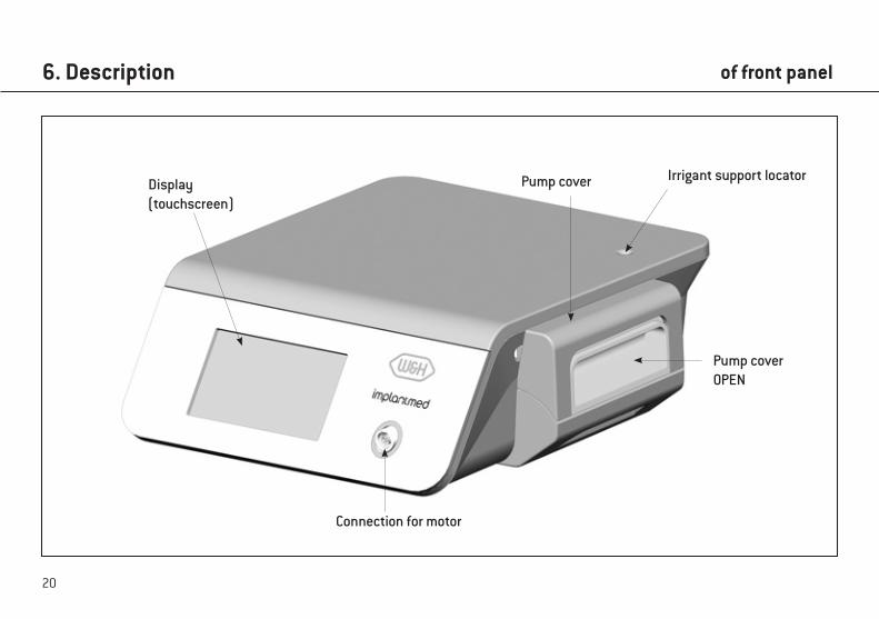
6. Description
Connection for motor
Display(touchscreen)
Pump coverOPEN
Pump cover Irrigant support locator
of front panel
21
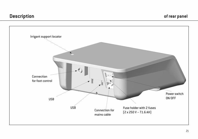
Description
Connection for foot control
Fuse holder with 2 fuses(2 x 250 V – T1.6 AH)Connection for
mains cable
Irrigant support locator
USB
USB
Power switch ON/OFF
of rear panel
22
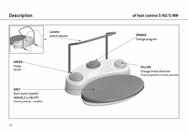
Description
ORANGEChange program
Locatorattach/detach
GREENPumpON/OFF
GREYStart motor (pedal)VARIABLE or ON/OFF(Factory setting = variable)
YELLOWChange motor directionForward operation/reverse operation
of foot control S-N2/S-NW
23
Description
ORANGES-N2 / S-NW: Change programPress the ORANGE button to change programs in ascending order. The motor direction is automatically set to forward operation every time the program is changed.
When changing from the last program to the first program a longer acoustic signal sounds (risk of injury).
ORANGES-NW: Switching between multiple control unitsPress the ORANGE button for 3 seconds
GREEN – pump ON/OFFOnly when the motor is stationary can the pump be switched on or off by pressing the GREEN button of the foot control.
YELLOW – change motor directionForward operation/reverse operationPress the YELLOW button to change from forward operation to reverse operation. A signal sounds on selection and the
“Forward/reverse operation mode” symbol flashes. Before the motor starts in reverse operation, 3 audible signals are given.
of foot control S-N2/S-NW
24
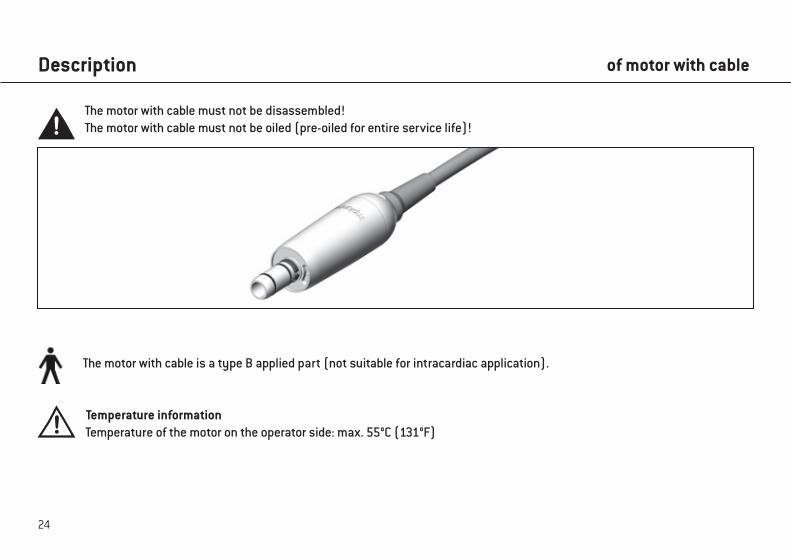
Description
The motor with cable is a type B applied part (not suitable for intracardiac application).
Temperature informationTemperature of the motor on the operator side: max. 55°C (131°F)
The motor with cable must not be disassembled!The motor with cable must not be oiled (pre-oiled for entire service life)!
of motor with cable
25
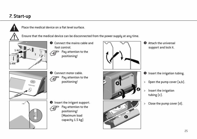
7. Start-up
Connect the mains cable and foot control.
Pay attention to the positioning!
Connect motor cable.Pay attention to the positioning!
Insert the irrigant support.Pay attention to the positioning! (Maximum load capacity 1.5 kg)
Place the medical device on a flat level surface.
Ensure that the medical device can be disconnected from the power supply at any time.
S-N2
S-NW
Attach the universal support and lock it.
Insert the irrigation tubing.
> Open the pump cover (a,b).
> Insert the irrigation tubing (c).
> Close the pump cover (d).
26
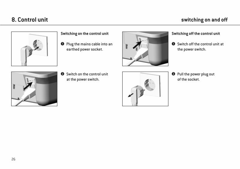
Switching on the control unit
Plug the mains cable into an earthed power socket.
Switch on the control unit at the power switch.
Pull the power plug out of the socket.
8. Control unit
Switching off the control unit
Switch off the control unit at the power switch.
switching on and off
27
9. Starting operation
The touch screen must only be touched using fingers.Using hard objects on the touch screen may scratch or damage the surface.
Setting up ImplantmedSwitch on your control unit and follow the directions of the setup wizard.The set-up wizard guides you through the various set-up stages up to the main menu:
> Language selection> Set Up Medical Device:
Customized: Create a userStandard: Default settings
Setup wizard
28
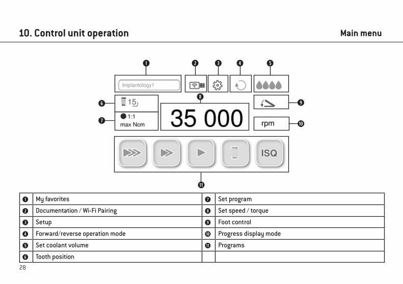
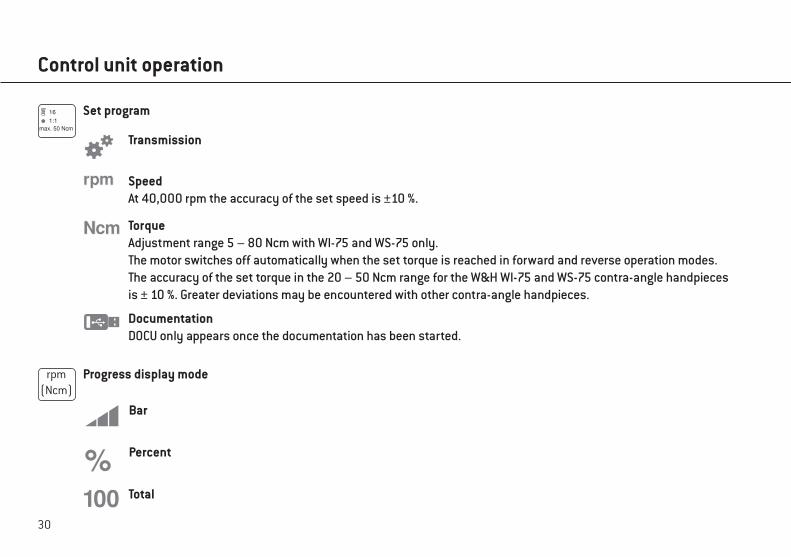
My favorites Set program
Documentation / Wi-Fi Pairing Set speed / torque
Setup Foot control
Forward/reverse operation mode Progress display mode
Set coolant volume Programs
Tooth position
10. Control unit operation Main menu
29
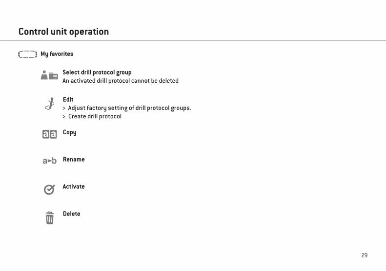
Edit > Adjust factory setting of drill protocol groups. > Create drill protocol
Copy
Rename
Activate
Delete
Select drill protocol groupAn activated drill protocol cannot be deleted
My favorites
Control unit operation
30
16
max. 50 Ncm1:1
SpeedAt 40,000 rpm the accuracy of the set speed is ±10 %.
Bar
Percent
Total
rpm (Ncm)
Progress display mode
Set program
Transmission
TorqueAdjustment range 5 – 80 Ncm with WI-75 and WS-75 only.The motor switches off automatically when the set torque is reached in forward and reverse operation modes.The accuracy of the set torque in the 20 – 50 Ncm range for the W&H WI-75 and WS-75 contra-angle handpieces is ± 10 %. Greater deviations may be encountered with other contra-angle handpieces.
Control unit operation
DocumentationDOCU only appears once the documentation has been started.
31
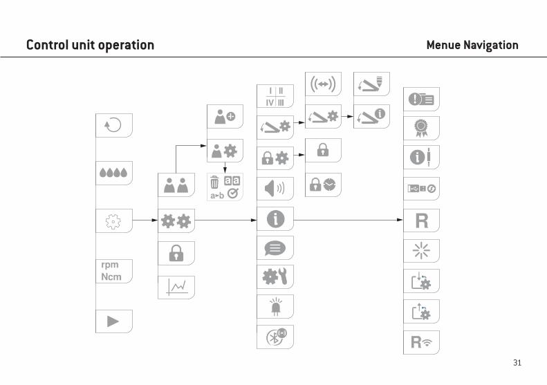
Control unit operation Menue Navigation
32
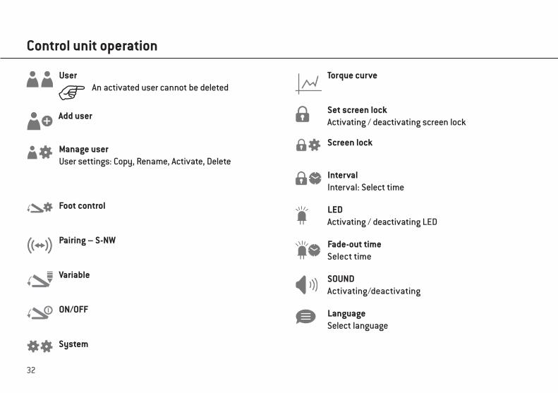
Control unit operation
UserAn activated user cannot be deleted
Manage userUser settings: Copy, Rename, Activate, Delete
Pairing – S-NW
Foot control
Variable
ON/OFF
Set screen lockActivating / deactivating screen lock
Screen lock
IntervalInterval: Select time
SOUNDActivating/deactivating
LanguageSelect language
System
Add user
Torque curve
LEDActivating / deactivating LED
Fade-out timeSelect time
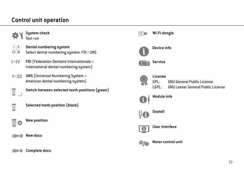
33
New docu
Complete docu
New position
LicenesGPL: GNU General Public LicenseLGPL: GNU Lesser General Public License
Module info
Service
User interface
Device info
Motor control unit
Control unit operation
System checkTest run
Dental numbering systemSelect dental numbering system: FDI / UNS
FDI (Féderation Dentaire Internationale = International dental numbering system)
UNS (Universal Numbering System = American dental numbering system)
Osstell
Switch between selected tooth positions (green)
Selected tooth position (black)
Wi-Fi-dongle
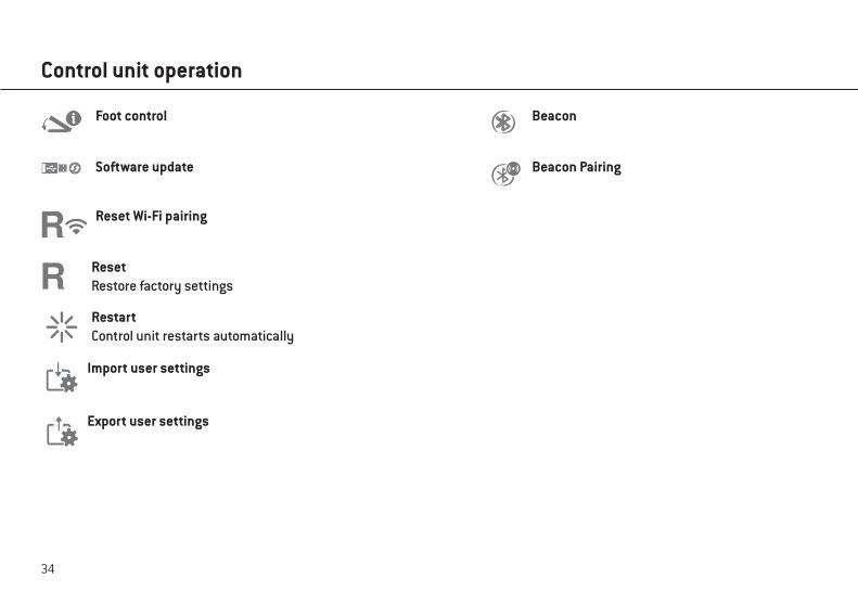
34
Software update
Reset Wi-Fi pairing
Control unit operation
ResetRestore factory settings
RestartControl unit restarts automatically
Import user settings
Export user settings
Beacon Foot control
Beacon Pairing
35
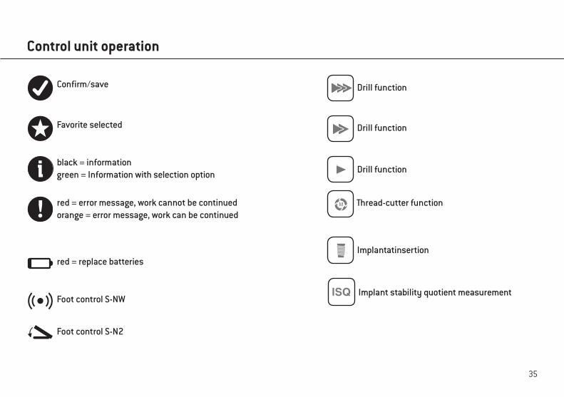
Control unit operation
black = informationgreen = Information with selection option
Confirm/save
red = error message, work cannot be continuedorange = error message, work can be continued
Favorite selected
red = replace batteries
Foot control S-NW
Foot control S-N2
Drill function
Drill function
Implantatinsertion
Drill function
Thread-cutter function
Implant stability quotient measurement
36
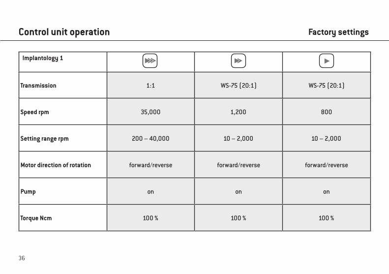
Control unit operation
Implantology 1
Transmission 1:1 WS-75 (20:1) WS-75 (20:1)
Speed rpm 35,000 1,200 800
Setting range rpm 200 – 40,000 10 – 2,000 10 – 2,000
Motor direction of rotation forward/reverse forward/reverse forward/reverse
Pump on on on
Torque Ncm 100 % 100 % 100 %
Factory settings
37
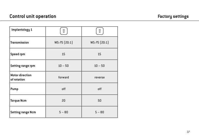
Control unit operation
Implantology 1
Transmission WS-75 (20:1) WS-75 (20:1)
Speed rpm 15 15
Setting range rpm 10 – 50 10 – 50
Motor directionof rotation
forward reverse
Pump off off
Torque Ncm 20 50
Setting range Ncm 5 – 80 5 – 80
Factory settings
38
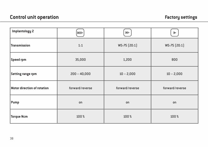
Control unit operation
Implantology 2
Transmission 1:1 WS-75 (20:1) WS-75 (20:1)
Speed rpm 35,000 1,200 800
Setting range rpm 200 – 40,000 10 – 2,000 10 – 2,000
Motor direction of rotation forward/reverse forward/reverse forward/reverse
Pump on on on
Torque Ncm 100 % 100 % 100 %
Factory settings
39
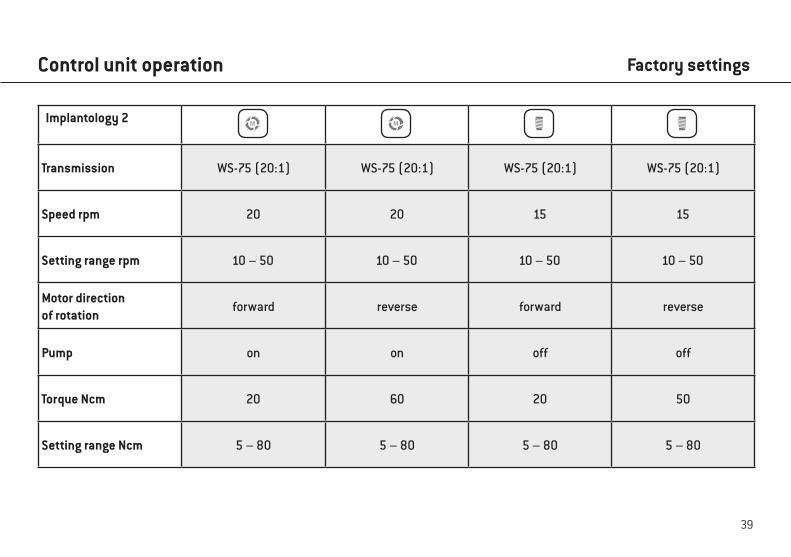
Control unit operation
Implantology 2
Transmission WS-75 (20:1) WS-75 (20:1) WS-75 (20:1) WS-75 (20:1)
Speed rpm 20 20 15 15
Setting range rpm 10 – 50 10 – 50 10 – 50 10 – 50
Motor directionof rotation
forward reverse forward reverse
Pump on on off off
Torque Ncm 20 60 20 50
Setting range Ncm 5 – 80 5 – 80 5 – 80 5 – 80
Factory settings
40
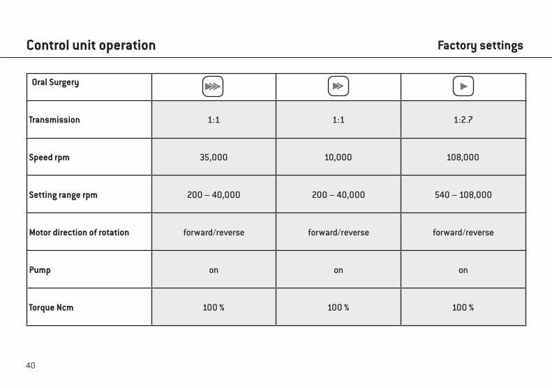
Oral Surgery
Transmission 1:1 1:1 1:2.7
Speed rpm 35,000 10,000 108,000
Setting range rpm 200 – 40,000 200 – 40,000 540 – 108,000
Motor direction of rotation forward/reverse forward/reverse forward/reverse
Pump on on on
Torque Ncm 100 % 100 % 100 %
Control unit operation Factory settings
41
Thread-cutter function (chip breaker mode)When the pedal (grey) on the foot control is pressed, the thread cutter rotates inwards until the set torque is reached.The control unit automatically switches to reverse operation when the set torque is reached.Disengaging and then re-engaging the pedal will switch the control unit back to forward operation.
If the thread cutter function is in reverse operation mode, the control unit can also start with the maximum torque.
Control unit operation Factory settings
42
Drill protocols, torque curves and ISQ values can only be documented in the thread-tapping function, implant insertion or ISQ measurement.Documentation must be activated or deactivated for each program.A USB stick is required to save the documentation.
> Never remove the USB stick while the motor is running. > Never remove the USB stick during the measurement.
Record documentation > Connect USB stick
Icon appears
> Enter ID > Enter date > Select tooth quadrant > Select tooth > Confirm selection
Documentation starts when the motor starts.
Control unit operation Documentation with USB stick
43
Control unit operation
Further documentation > Add new position > Start new docu > Complete docu
When the motor stops, a diagram appears, which is automatically saved to the USB stick.
Edit documentation
A text file (csv) and a PDF file are saved on the USB stick.The text file can be opened in Microsoft® Excel®* for editing.The pdf file can be opened in Adobe® Reader®**.
* Microsoft® Excel® is a registered trademark of the Microsoft® Corporation in the United States of America and/or other countries.** Adobe® Reader® is a registered trademark of Adobe Systems Incorporated in the United States of America and/or other countries.
Documentation with USB stick
44
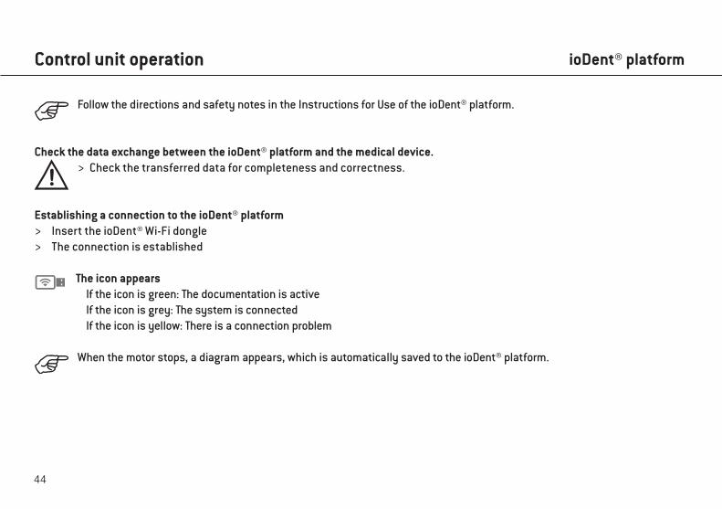
Follow the directions and safety notes in the Instructions for Use of the ioDent® platform.
Check the data exchange between the ioDent® platform and the medical device. > Check the transferred data for completeness and correctness.
Establishing a connection to the ioDent® platform > Insert the ioDent® Wi-Fi dongle > The connection is established
The icon appears If the icon is green: The documentation is active If the icon is grey: The system is connected If the icon is yellow: There is a connection problem
When the motor stops, a diagram appears, which is automatically saved to the ioDent® platform.
Control unit operation ioDent® platform
45
Control unit operation ioDent® platform
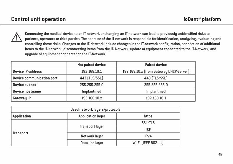
Connecting the medical device to an IT network or changing an IT network can lead to previously unidentified risks to patients, operators or third parties. The operator of the IT network is responsible for identification, analyzing, evaluating and controlling these risks. Changes to the IT-Network include changes in the IT-network configuration, connection of additional items to the IT-Network, disconnecting items from the IT- Network, update of equipment connected to the IT-Network, and upgrade of equipment connected to the IT-Network.
Not paired device Paired device
Device IP-address 192.168.10.1 192.168.10.x (from Gateway DHCP-Server)
Device communication port 443 (TLS/SSL) 443 (TLS/SSL)
Device subnet 255.255.255.0 255.255.255.0
Device hostname Implantmed Implantmed
Gateway IP 192.168.10.x 192.168.10.1
Used network layers/protocols
Application Application layer https
Transport
Transport layerSSL/TLS
TCP
Network layer IPv4
Data link layer Wi-Fi (IEEE 802.11)
46
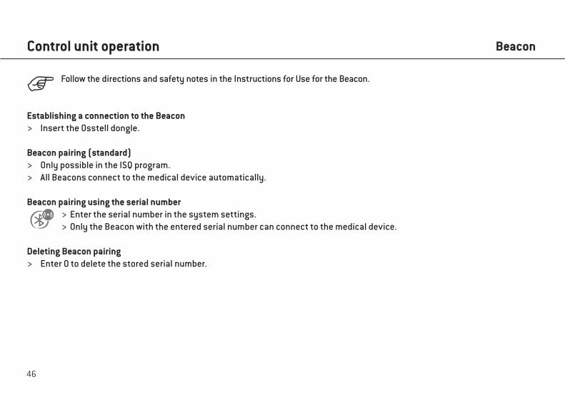
Follow the directions and safety notes in the Instructions for Use for the Beacon.
Establishing a connection to the Beacon > Insert the Osstell dongle.
Beacon pairing (standard) > Only possible in the ISQ program. > All Beacons connect to the medical device automatically.
Beacon pairing using the serial number > Enter the serial number in the system settings. > Only the Beacon with the entered serial number can connect to the medical device.
Deleting Beacon pairing > Enter 0 to delete the stored serial number.
Control unit operation Beacon
47
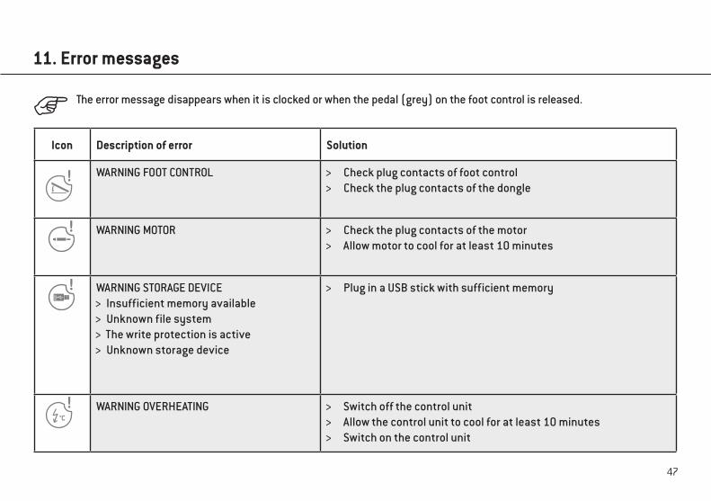
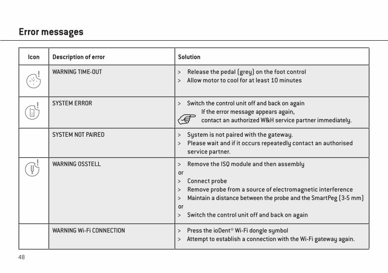
11. Error messages
Icon Description of error Solution
WARNING FOOT CONTROL > Check plug contacts of foot control > Check the plug contacts of the dongle
WARNING MOTOR > Check the plug contacts of the motor > Allow motor to cool for at least 10 minutes
WARNING STORAGE DEVICE > Insufficient memory available > Unknown file system > The write protection is active > Unknown storage device
> Plug in a USB stick with sufficient memory
WARNING OVERHEATING > Switch off the control unit > Allow the control unit to cool for at least 10 minutes > Switch on the control unit
The error message disappears when it is clocked or when the pedal (grey) on the foot control is released.
48
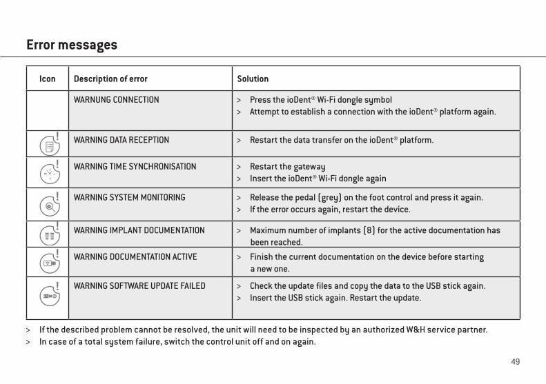
Icon Description of error Solution
WARNING TIME-OUT > Release the pedal (grey) on the foot control > Allow motor to cool for at least 10 minutes
SYSTEM ERROR > Switch the control unit off and back on again If the error message appears again, contact an authorized W&H service partner immediately.
SYSTEM NOT PAIRED > System is not paired with the gateway. > Please wait and if it occurs repeatedly contact an authorised
service partner.
WARNING OSSTELL > Remove the ISQ module and then assemblyor
> Connect probe > Remove probe from a source of electromagnetic interference > Maintain a distance between the probe and the SmartPeg (3-5 mm)
or > Switch the control unit off and back on again
WARNING Wi-Fi CONNECTION > Press the ioDent® Wi-Fi dongle symbol> Attempt to establish a connection with the Wi-Fi gateway again.
Error messages
49
> If the described problem cannot be resolved, the unit will need to be inspected by an authorized W&H service partner. > In case of a total system failure, switch the control unit off and on again.
Icon Description of error Solution
WARNUNG CONNECTION > Press the ioDent® Wi-Fi dongle symbol> Attempt to establish a connection with the ioDent® platform again.
WARNING DATA RECEPTION > Restart the data transfer on the ioDent® platform.
WARNING TIME SYNCHRONISATION > Restart the gateway> Insert the ioDent® Wi-Fi dongle again
WARNING SYSTEM MONITORING > Release the pedal (grey) on the foot control and press it again.> If the error occurs again, restart the device.
WARNING IMPLANT DOCUMENTATION > Maximum number of implants (8) for the active documentation has been reached.
WARNING DOCUMENTATION ACTIVE > Finish the current documentation on the device before starting a new one.
WARNING SOFTWARE UPDATE FAILED > Check the update files and copy the data to the USB stick again.> Insert the USB stick again. Restart the update.
Error messages
50
12. Hygiene and maintenance
Follow your local and national laws, directives, standards and guidelines for cleaning, disinfectionand sterilization.
> Wear protective clothing, safety glasses, face mask and gloves.
> Use only oil-free, filtered compressed air with a maximum operating pressure of 3 bar for manual drying.
Cleaning agents and disinfectants > Read the notes, follow the instructions and heed the warnings provided by the manufacturers of cleaning agents and/
or disinfectants. > Use only detergents which are intended for cleaning and/or disinfecting medical devices made of metal and plastic. > It is imperative to comply with the concentrations and exposure times specified by the manufacturer of the
disinfectant. > Use disinfectants which have been tested and found effective by the Verbund für Angewandte Hygiene e.V.
(VAH = Association for Applied Hygiene), the Österreichischen Gesellschaft für Hygiene, Mikrobiologie und Präventivmedizin (ÖGHMP = Austrian Society for Hygiene, Microbiology and Preventive Medicine), the Food and Drug Administration (FDA) and the U.S. Environmental Protection Agency (EPA).
> The user is responsible for validating its process if the specified cleaning agents and disinfectants are not available.
General notes
51
Hygiene and maintenance
The product lifetime and the medical device’s ability to operate correctly are mainly determined bymechanical stress during use and chemical influences due to processing.
> Send worn or damaged medical devices and/or medical devices with material changes to an authorized W&H service partner.
Processing cycles > We recommend a regular service for the W&H motor with cable after 500 processing cycles or one year. > We recommend a regular service for the W&H universal support after 250 processing cycles.
Limitations on processing
52
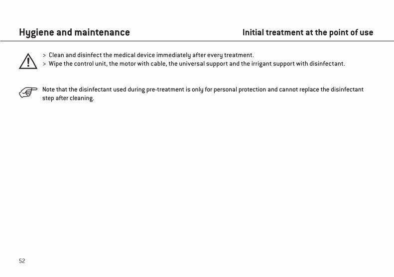
> Clean and disinfect the medical device immediately after every treatment. > Wipe the control unit, the motor with cable, the universal support and the irrigant support with disinfectant.
Note that the disinfectant used during pre-treatment is only for personal protection and cannot replace the disinfectant step after cleaning.
Hygiene and maintenance Initial treatment at the point of use
53
Hygiene and maintenance
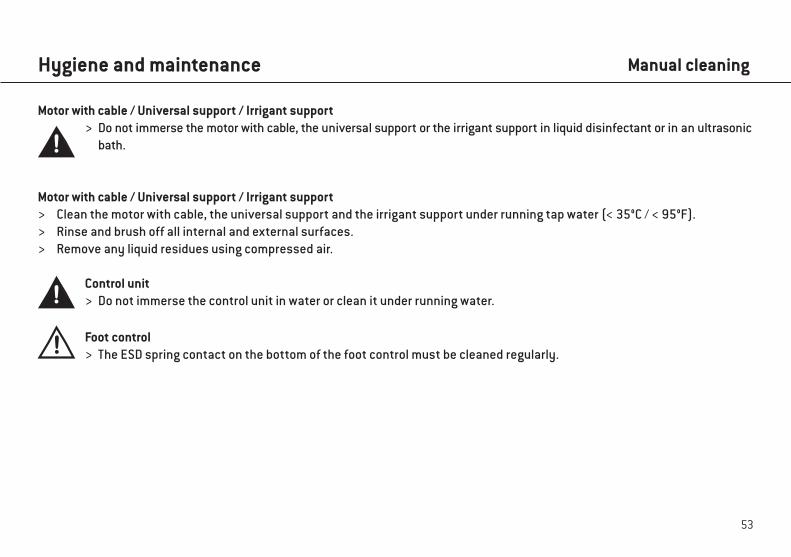
Motor with cable / Universal support / Irrigant support > Do not immerse the motor with cable, the universal support or the irrigant support in liquid disinfectant or in an ultrasonic
bath.
Motor with cable / Universal support / Irrigant support > Clean the motor with cable, the universal support and the irrigant support under running tap water (< 35°C / < 95°F). > Rinse and brush off all internal and external surfaces. > Remove any liquid residues using compressed air.
Control unit > Do not immerse the control unit in water or clean it under running water.
Foot control > The ESD spring contact on the bottom of the foot control must be cleaned regularly.
Manual cleaning
54
Motor with cable / Universal support / Irrigant support
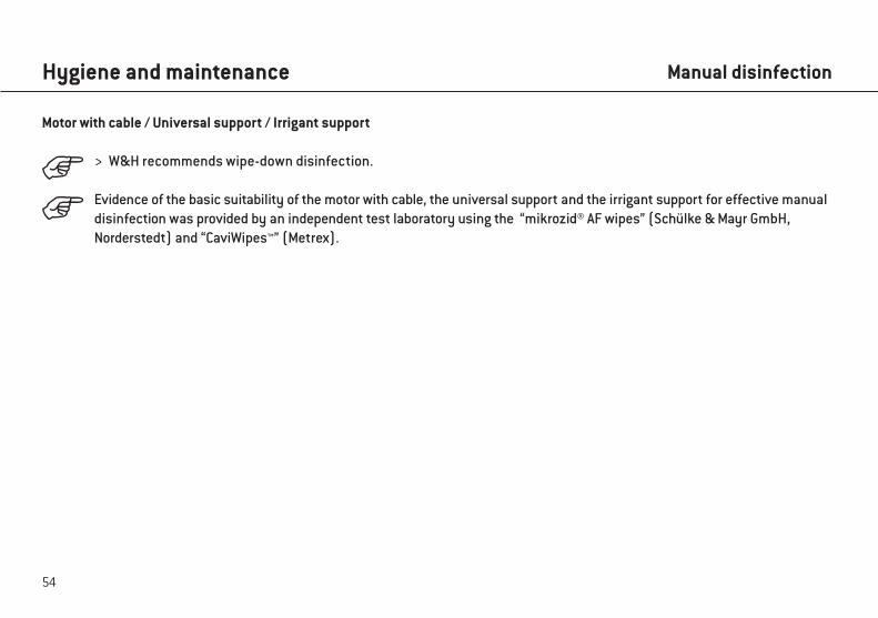
> W&H recommends wipe-down disinfection.
Evidence of the basic suitability of the motor with cable, the universal support and the irrigant support for effective manual disinfection was provided by an independent test laboratory using the “mikrozid® AF wipes” (Schülke & Mayr GmbH, Norderstedt) and “CaviWipes™” (Metrex).
Hygiene and maintenance Manual disinfection
55
Hygiene and maintenance
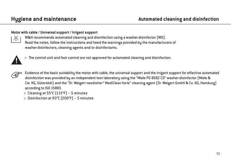
Motor with cable / Universal support / Irrigant supportW&H recommends automated cleaning and disinfection using a washer-disinfector (WD).Read the notes, follow the instructions and heed the warnings provided by the manufacturers of washer-disinfectors, cleaning agents and/or disinfectants.
> The control unit and foot control are not approved for automated cleaning and disinfection.
Evidence of the basic suitability the motor with cable, the universal support and the irrigant support for effective automated disinfection was provided by an independent test laboratory using the “Miele PG 8582 CD” washer-disinfector (Miele & Cie. KG, Gütersloh) and the “Dr. Weigert neodisher® MediClean forte” cleaning agent (Dr. Weigert GmbH & Co. KG, Hamburg) according to ISO 15883. > Cleaning at 55°C (131°F) – 5 minutes > Disinfection at 93°C (200°F) – 5 minutes
Automated cleaning and disinfection
56
Hygiene and maintenance
Motor with cable / Universal support / Irrigant support > Ensure that the motor with cable, the universal support and the irrigant support are completely dry internally and
externally after cleaning and disinfection.
> Remove any liquid residues using compressed air.
Drying
57
Hygiene and maintenance
Inspection – Motor with cable / Universal support / Irrigant support > Check the motor with cable, the universal support and the irrigant support after cleaning and disinfection for damage,
visible residual soiling and surface changes. > Reprocess any motor with cable, universal support and irrigant support that are still soiled. > Sterilize the motor with cable and the universal support following cleaning and disinfection.
Inspection, maintenance and testing
58
Hygiene and maintenance
Motor with cable / Universal support Wrap the motor with cable and the universal support in sterilization packages that meet the following requirements:
> The sterilization package must meet the applicable standards in respect of quality and use and must be suitable for the sterilization procedure.
> The sterilization package must be large enough for the sterilization goods. > The loading sterilization package must not be under tension.
Packaging
59
Hygiene and maintenance
Motor with cable / Universal support
W&H recommends sterilization according to EN 13060, EN 285 or ANSI/AAMI ST55.
> Read the notes, follow the instructions and heed the warnings provided by the manufacturers of steam sterilizers. > The program selected must be suitable for the motor with cable and the universal support.
Recommended sterilization procedures > “Dynamic-air-removal prevacuum cycle” (type B) / “Steam-flush pressure-pulse cycle” (type S)*/**
134°C (273°F) for at least 3 minutes, 132°C (270°F) for at least 4 minutes > “Gravity-displacement cycle” (type N)**
121°C (250°F) for at least 30 minutes > Maximum sterilization temperature 135°C (275°F)
Sterilization
60
Hygiene and maintenance Sterilization
Evidence of the basic suitability of the motor with cable and the universal support for effective sterilization was provided by an independent test laboratory using the LISA 517 B17L* steam sterilizer (W&H Sterilization S.r.l., Brusaporto (BG)), the Systec VE-150* steam sterilizer (Systec) and the CertoClav MultiControl MC2-S09S273** steam sterilizer (CertoClav GmbH, Traun).
“Dynamic-air-removal prevacuum cycle” (type B): 134°C (273°F) – 3 minutes*, 132°C (270 °F) – 4 minutes*/**“Steam-flush pressure-pulse cycle” (type S): 134°C (273°F) – 3 minutes*, 132°C (270 °F) – 4 minutes*/**“Gravity-displacement cycle” (type N): 121°C (250°F) – 30 minutes**
Drying times:“Dynamic-air-removal prevacuum cycle” (type B): 132°C (270°F) – 30 minutes**“Steam-flush pressure-pulse cycle” (type S): 132°C (270°F) – 30 minutes**“Gravity-displacement cycle” (type N): 121°C (250°F) – 30 minutes**
* EN 13060, EN 285, ISO 17665** ANSI/AAMI ST55, ANSI/AAMI ST79
61
Motor with cable / Universal support > Store sterile goods dust-free and dry. > The shelf life of the sterile goods depends on the storage conditions and type of packaging.
Hygiene and maintenance Storage
62
13. Servicing
Periodic inspectionRegular periodic inspection of the function and safety of the medical device is necessary and should be carried out at least once every three years, unless shorter intervals are prescribed by law.The periodic inspection covers the complete medical device and must only be performed by an authorized service partner.
63
Servicing
Repairs and returnsIn the event of operating malfunctions immediately contact an authorized W&H service partner.Repairs and maintenance work must only be undertaken by an authorized W&H service partner.
> Ensure that the medical device has been completely processed before returning it.
> Always return equipment in the original packaging. > Do not coil the cable around the motor and do not twist or kink the motor cable. (Risk of damage) > Foot control S-NW: Remove the batteries.
64
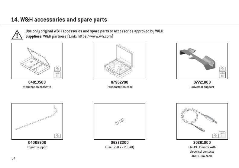
14. W&H accessories and spare parts
Use only original W&H accessories and spare parts or accessories approved by W&H.Suppliers: W&H partners (Link: https://www.wh.com)
04013500Sterilization cassette
07962790Transportation case
07721800Universal support
04005900Irrigant support
06352200Fuse (250 V - T1.6AH)
30281000EM-19 LC motor with electrical contacts
and 1.8 m cable
65
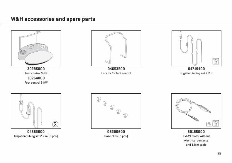
W&H accessories and spare parts
06290600Hose clips (5 pcs)
04363600Irrigation tubing set 2.2 m (6 pcs)
30285000Foot control S-N2
30264000Foot control S-NW
04653500Locator for foot control
30185000EM-19 motor without
electrical contacts and 1.8 m cable
04719400Irrigation tubing set 2,2 m
66
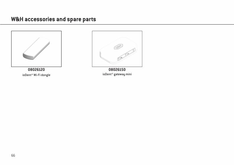
W&H accessories and spare parts
08026120ioDent® Wi-Fi dongle
08026150ioDent® gateway mini
67
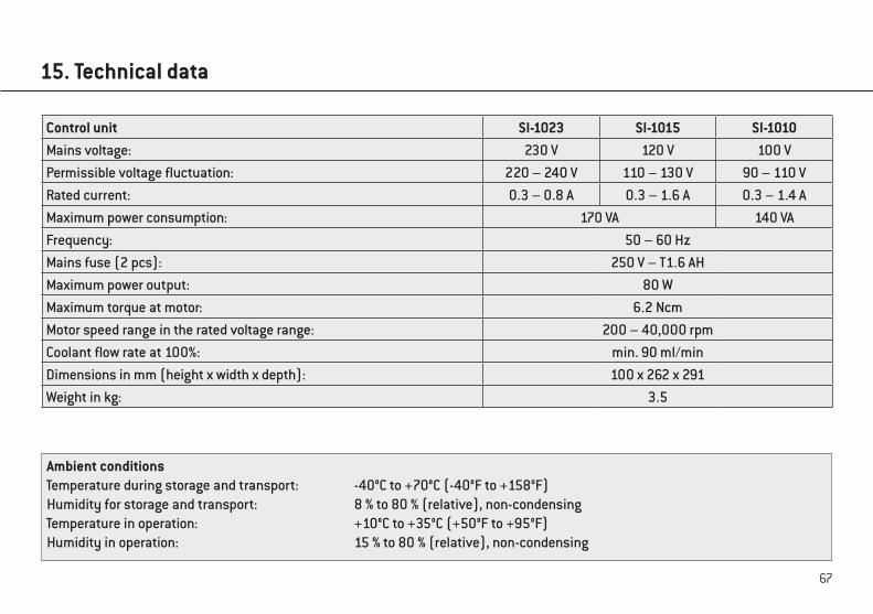
15. Technical data
Ambient conditionsTemperature during storage and transport: -40°C to +70°C (-40°F to +158°F)Humidity for storage and transport: 8 % to 80 % (relative), non-condensingTemperature in operation: +10°C to +35°C (+50°F to +95°F)Humidity in operation: 15 % to 80 % (relative), non-condensing
Control unit SI-1023 SI-1015 SI-1010Mains voltage: 230 V 120 V 100 VPermissible voltage fluctuation: 220 – 240 V 110 – 130 V 90 – 110 VRated current: 0.3 – 0.8 A 0.3 – 1.6 A 0.3 – 1.4 AMaximum power consumption: 170 VA 140 VAFrequency: 50 – 60 HzMains fuse (2 pcs): 250 V – T1.6 AHMaximum power output: 80 WMaximum torque at motor: 6.2 NcmMotor speed range in the rated voltage range: 200 – 40,000 rpmCoolant flow rate at 100%: min. 90 ml/minDimensions in mm (height x width x depth): 100 x 262 x 291Weight in kg: 3.5
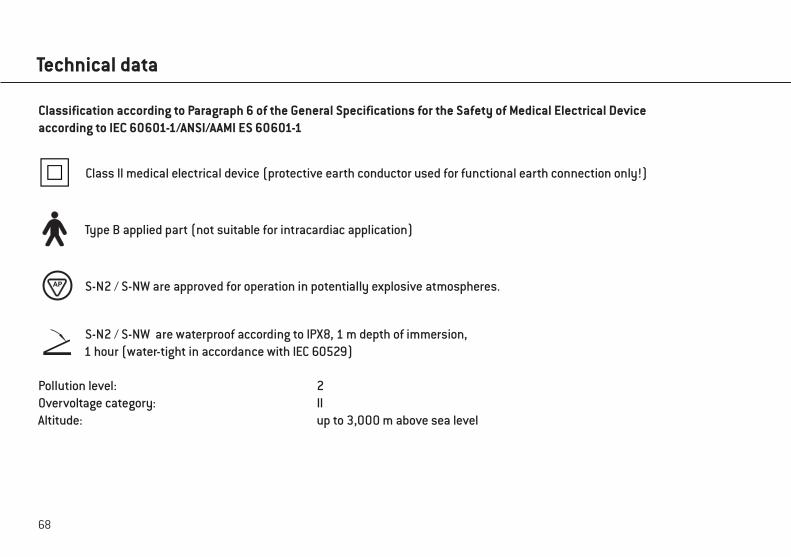
68
Technical data
S-N2 / S-NW are waterproof according to IPX8, 1 m depth of immersion,1 hour (water-tight in accordance with IEC 60529)
Pollution level: 2Overvoltage category: IIAltitude: up to 3,000 m above sea level
Class II medical electrical device (protective earth conductor used for functional earth connection only!)
Type B applied part (not suitable for intracardiac application)
S-N2 / S-NW are approved for operation in potentially explosive atmospheres.
Classification according to Paragraph 6 of the General Specifications for the Safety of Medical Electrical Deviceaccording to IEC 60601-1/ANSI/AAMI ES 60601-1
AP
69
16. Disposal
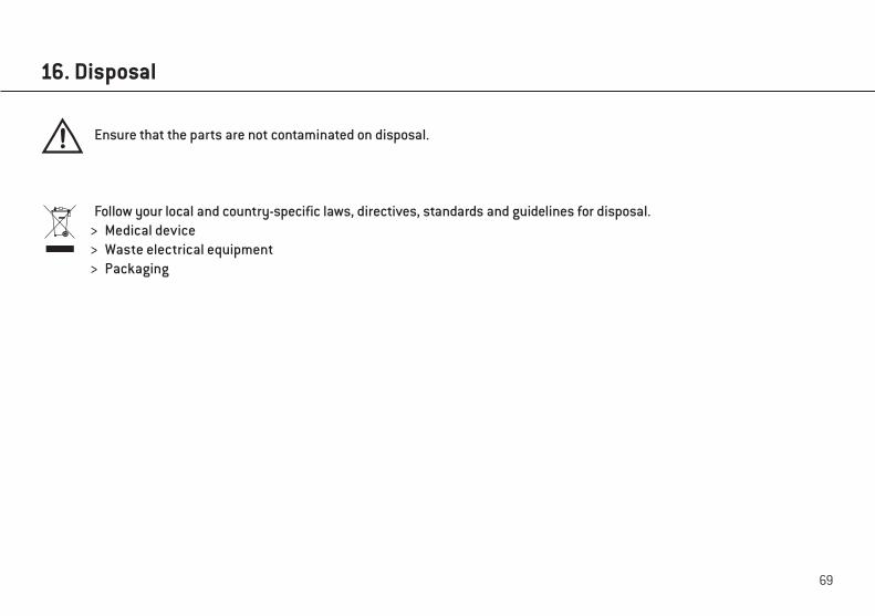
Ensure that the parts are not contaminated on disposal.
Follow your local and country-specific laws, directives, standards and guidelines for disposal. > Medical device > Waste electrical equipment > Packaging

W&H course certificateThe user has been trained to use the medical device correctly in accordance with the legal regulations (medical devices marketing regulations, medical devices act). Particular attention has been paid to the chapters on safety notes, start-up, operation, hygiene and maintenance, and service (regular inspections).
Product name Serial number (SN)
Manufacturer with address
Distributor with address
Name of the user Date of birth and/or personnel number
Hospital/dental practice/department with address
Signature of the user
The signature confirms that the user has been trained to use the medical device and has understood the content.
Name of the instructor Date of instruction
Address of the instructor
Signature of the instructor
for the user

The user has been trained to use the medical device correctly in accordance with the legal regulations (medical devices marketing regulations, medical devices act). Particular attention has been paid to the chapters on safety notes, start-up, operation, hygiene and maintenance, and service (regular inspections).
Product name Serial number (SN)
Manufacturer with address
Distributor with address
Name of the user Date of birth and/or personnel number
Hospital/dental practice/department with address
Signature of the user
The signature confirms that the user has been trained to use the medical device and has understood the content.
Name of the instructor Date of instruction
Address of the instructor
Signature of the instructor
W&H course certificate for the instructor

E x p l a na ti o n o f wa r ra n t y te r m s
24 m o n th s w ar r an t y
This W&H product has been manufactured with great care by highly qualified specialists. A wide variety of tests and controlsguarantees faultless operation. Please note that claims under warranty can only be validated when all the directions in theInstructions for Use have been followed.
As the manufacturer, W&H is liable for material or manufacturing defects within a warranty period of 24 months from the date of purchase. Accessories and consumables (universal support, coolant hose, irrigant support, fuse, locator for foot control, hose clips, mains cable, sterilization cassette) are not covered by the warranty.
We accept no responsibility for damage caused by incorrect handling or by repairs carried out by third parties not authorized to do so by W&H!
Claims under warranty – accompanied by proof of purchase, must be sent to the vendor or to an authorized W&H service partner. The provision of service under warranty extends neither the warranty period nor any other guarantee period.
74
Authorized W&H service partners
Find your nearest authorized W&H service partner at http://wh.comSimply go to the menu option “Service” for full details.
Or simply scan the QR code.
75
Manufacturer’s declaration
Man
ufac
ture
r’s d
ecla
ratio
n
Elec
trom
agne
tic c
ompa
tibili
ty (E
MC
) W
ARN
ING
: The
use
of c
able
s, p
ower
sup
plie
s, a
cces
sorie
s ot
her t
han
thos
e sp
ecifi
ed b
y th
e m
anuf
actu
rer m
ay re
sult
in
incr
ease
d em
issi
on a
nd/o
r dec
reas
ed im
mun
ity. O
nly
use
orig
inal
W&H
acc
esso
ries.
ca
bles
and
acc
esso
ries
leng
th
refe
renc
e C
ount
ry s
peci
fic m
ains
cab
le a
ccor
ding
to W
&H
coun
try li
st
2.5
to 3
.1 m
M
anuf
actu
rer:
Felle
r Gm
bH
Mot
or w
ith c
able
EM
-19
1.8
m
Man
ufac
ture
r: W
&H
REF
301
85xx
x M
otor
with
alte
rnat
ive
cabl
e EM
-19
3.5
m
Man
ufac
ture
r: W
&H
REF
301
85xx
x M
otor
with
cab
le (w
ith L
ED)
EM-1
9 LC
1.
8 m
M
anuf
actu
rer:
W&H
R
EF 3
0281
xxx
Mot
or w
ith a
ltern
ativ
e ca
ble
(with
LED
) EM
-19
LC
3.5
m
Man
ufac
ture
r: W
&H
REF
302
81xx
x Fo
ot c
ontro
ller
S-N
2 2.
85 m
M
anuf
actu
rer:
W&H
R
EF 3
0285
xxx
Foot
con
trolle
r S-
NW
W
irele
ss tr
ansm
issi
on
Man
ufac
ture
r: W
&H
REF
302
64xx
x
CAN
Don
gle
Wire
less
tran
smis
sion
M
anuf
actu
rer:
W&H
R
EF 0
7759
700
Ope
rate
the
prod
uct i
n a
plac
e w
ith a
max
imum
dis
tanc
e to
ele
ctric
al a
nd m
agne
tic in
terfe
ring
trans
mitt
ers.
If o
pera
tion
of t
he
prod
uct c
lose
to o
ther
dev
ices
or t
oget
her i
n a
stac
k is
nec
essa
ry, o
bser
ve th
e co
rrect
func
tion
of th
e sy
stem
. El
ectr
omag
netic
Imm
unity
I (T
able
2, I
EC 6
0601
-1-2
:200
7)
The
prod
uct i
s su
itabl
e fo
r use
in a
spe
cific
ele
ctro
mag
netic
env
ironm
ent.
The
cust
omer
and
/or t
he u
ser o
f the
pro
duct
sho
uld
assu
re th
at it
is u
sed
in a
n el
ectro
mag
netic
env
ironm
ent a
s de
scrib
ed b
elow
. Im
mun
ity T
est
IEC
606
01-L
evel
(3
rd E
d.)
IEC
606
01-L
evel
(4
th E
d.)
Com
plia
nce
Leve
l El
ectro
mag
netic
Env
ironm
ent
Gui
danc
e El
ectro
stat
ic
disc
harg
e (E
SD)
IEC
610
00-4
-2
± 6
kV c
onta
ct
± 8
kV a
ir ±
8 kV
con
tact
±
15 k
V ai
r ±
8 kV
con
tact
±
15 k
V ai
r Fl
oor s
houl
d be
woo
d, c
oncr
ete
or
cera
mic
tile
. If f
loor
s ar
e co
vere
d w
ith
synt
hetic
mat
eria
l, th
e re
lativ
e hu
mid
ity s
houl
d be
at l
east
30
%
Elec
trica
l fas
t tra
nsie
nt/b
urst
s IE
C 6
1000
-4-4
± 2
kV fo
r pow
er
supp
ly li
nes
± 1
kV fo
r in
put/o
utpu
t lin
es
5kH
z re
petit
ion
rate
± 2
kV fo
r pow
er
supp
ly li
nes
± 1
kV fo
r in
put/o
utpu
t lin
es
100k
Hz
repe
titio
n ra
te
± 2
kV fo
r pow
er
supp
ly li
nes
± 1
kV fo
r in
put/o
utpu
t lin
es
Both
repe
titio
n ra
tes
Mai
ns p
ower
qua
lity
shou
ld b
e th
at o
f a
typi
cal c
omm
erci
al a
nd/o
r hos
pita
l en
viro
nmen
t
Surg
e IE
C61
000-
4-5
± 1
kV
line(
s) to
line
(s)
± 2
kV
line(
s) to
ear
th
± 1
kV
line(
s) to
line
(s)
± 2
kV
line(
s) to
ear
th
± 1
kV
line(
s) to
line
(s)
± 2
kV
line(
s) to
ear
th
Mai
ns p
ower
qua
lity
shou
ld b
e th
at o
f a
typi
cal c
omm
erci
al a
nd/o
r hos
pita
l en
viro
nmen
t
Volta
ge d
ips,
sho
rt in
terru
ptio
ns a
nd
volta
ge v
aria
tions
on
pow
er s
uppl
y in
put
lines
IE
C61
000-
4-11
<5%
UT
(>95
% d
ip in
UT)
fo
r 0.5
cyc
le
40%
UT
(60%
dip
in U
T)
for 5
cyc
les
70%
UT
(30%
dip
in U
T)
for 2
5 cy
cles
<5
% U
T (>
95%
dip
in U
T)
for 5
sec
0% U
T 0.
5 cy
cle
@
0°,4
5°,9
0°,1
35°,1
80°,2
25°,2
70°
& 31
5°
0% U
T 1
cycl
e an
d 70
% U
T 25/
30*
cycl
es @
0°
0% U
T 25
0/30
0*
cycl
e
Com
plie
s to
bot
h ed
ition
s re
quire
men
ts
Mai
ns p
ower
qua
lity
shou
ld b
e th
at o
f a
typi
cal c
omm
erci
al a
nd/o
r hos
pita
l en
viro
nmen
t. If
the
user
of t
he
prod
uct r
equi
res
cont
inue
d op
erat
ion
durin
g po
wer
mai
ns in
terru
ptio
ns, i
t is
reco
mm
ende
d th
at th
e pr
oduc
t be
pow
ered
from
an
unin
terru
ptib
le
pow
er s
uppl
y or
a b
atte
ry.
Pow
er
frequ
ency
(50/
60 H
z)
mag
netic
fiel
d IE
C 6
1000
-4-8
3A/m
30
A/m
30
A/m
Po
wer
freq
uenc
y m
agne
tic fi
elds
sh
ould
be
at le
vels
cha
ract
eris
tic o
f a
typi
cal l
ocat
ion
in a
typi
cal
com
mer
cial
or h
ospi
tal e
nviro
nmen
t. N
ote:
UT
is th
e m
ains
(AC
) vol
tage
bef
ore
appl
y te
st le
vels
* 2
5/30
(250
/300
) mea
ns c
ycle
s at
50/
60H
z
76
Elec
trom
agne
tic Im
mun
ity II
(Tab
le 4
, IEC
606
01-1
-2:2
007)
Th
e pr
oduc
t is
suita
ble
for u
se in
a s
peci
fic e
lect
rom
agne
tic e
nviro
nmen
t. Th
e cu
stom
er a
nd/o
r th
e us
er o
f the
pro
duct
sho
uld
assu
re th
at it
is u
sed
in a
n el
ectro
mag
netic
env
ironm
ent a
s de
scrib
ed b
elow
. Im
mun
ity T
est
IEC
606
01-L
evel
(3
rd E
d.)
IEC
606
01-L
evel
(4
th E
d.)
Com
plia
nce
Leve
l El
ectro
mag
netic
Env
ironm
ent
Gui
danc
e C
ondu
cted
RF
IEC
610
00-4
-6
Rad
iate
d R
F IE
C 6
1000
-4-3
3 V r
ms
150
kHz
to 8
0 M
Hz
3 V/
m
80 M
Hz
to 2
.5
GH
z
3 V r
ms
150
kHz
to 8
0 M
Hz
6 V r
ms i
n IS
M a
nd a
mat
eur
radi
o ba
nds*
be
twee
n 0,
15
MH
z an
d 80
MH
z 10
V/m
80
MH
z to
2.7
G
Hz
6 V r
ms
10 V
/m
Porta
ble
and
mob
ile R
F co
mm
unic
atio
ns e
quip
men
t sho
uld
be
used
no
clos
er to
any
par
t of t
he
prod
uct,
incl
udin
g ca
bles
, tha
n th
e re
com
men
ded
sepa
ratio
n di
stan
ce
calc
ulat
ed fr
om th
e eq
uatio
n ap
plic
able
to th
e fre
quen
cy o
f the
tra
nsm
itter
.
Rec
omm
ende
d se
para
tion
dist
ance
: d
= 1.
2P
d =
1.2
P fo
r 80
MH
z to
800
MH
z
d =
2.3
P fo
r 800
MH
z to
2.5
GH
z
whe
re P
is th
e m
axim
um o
utpu
t po
wer
ratin
g of
the
trans
mitt
er in
Wat
t (W
) acc
ordi
ng to
the
trans
mitt
er
man
ufac
ture
r and
d is
the
re-
com
men
ded
sepa
ratio
n di
stan
ce in
m
eter
s (m
)
Fiel
d st
reng
ths
from
fixe
d R
F tra
nsm
itter
s, a
s de
term
ined
by
an
elec
trom
agne
tic s
ite s
urve
y a ,
shou
ld
be le
ss th
an th
e co
mpl
ianc
e le
vel b i
n ea
ch fr
eque
ncy
rang
e
Inte
rfere
nce
may
occ
ur in
th
e vi
cini
ty o
f equ
ipm
ent
mar
ked
with
the
sym
bol
desc
ribed
late
ral.
Not
e 1:
At 8
0 M
Hz
and
800M
Hz,
the
high
er fr
eque
ncy
rang
e ap
plie
s.
Not
e 2:
The
se g
uide
lines
may
not
app
ly in
all
situ
atio
ns. E
lect
rom
agne
tic p
ropa
gatio
n is
affe
cted
by
abso
rptio
n an
d re
flect
ion
from
stru
ctur
es, o
bjec
ts, p
eopl
e an
d an
imal
s.
* The
ISM
(ind
ustri
al, s
cien
tific
and
med
ical
) ban
ds b
etw
een
0,15
MH
z an
d 80
MH
z ar
e 6,
765
MH
z to
6,7
95 M
Hz;
13,
553
MH
z to
13,
567
MH
z; 2
6,95
7 M
Hz
to 2
7,28
3 M
Hz;
and
40,
66 M
Hz
to 4
0,70
MH
z. T
he a
mat
eur r
adio
ban
ds b
etw
een
0,15
M
Hz
and
80 M
Hz
are
1,8
MH
z to
2,0
MH
z, 3
,5 M
Hz
to 4
,0 M
Hz,
5,3
MH
z to
5,4
MH
z, 7
MH
z to
7,3
MH
z, 1
0,1
MH
z to
10,
15
MH
z, 1
4 M
Hz
to 1
4,2
MH
z, 1
8,07
MH
z to
18,
17 M
Hz,
21,
0 M
Hz
to 2
1,4
MH
z, 2
4,89
MH
z to
24,
99 M
Hz,
28,
0 M
Hz
to 2
9,7
MH
z an
d 50
,0 M
Hz
to 5
4,0
MH
z.
a Fie
ld s
treng
ths
from
fixe
d tra
nsm
itter
s, s
uch
as b
ase
stat
ions
for r
adio
(cel
lula
r/cor
dles
s) te
leph
ones
and
land
mob
ile
radi
os, a
mat
eur r
adio
, AM
and
FM
radi
o br
oadc
ast a
nd T
V br
oadc
ast c
anno
t be
pred
icte
d th
eore
tical
ly w
ith a
ccur
acy.
To
asse
ss th
e el
ectro
mag
netic
env
ironm
ent d
ue to
fixe
d R
F tra
nsm
itter
s, a
n el
ectro
mag
netic
site
sur
vey
shou
ld b
e co
nsid
ered
, if
the
mea
sure
d fie
ld s
treng
th in
the
loca
tion
in w
hich
the
prod
uct i
s us
ed e
xcee
ds th
e ap
plic
able
RF
com
plia
nce
leve
l ab
ove,
the
prod
uct s
houl
d be
obs
erve
d, a
dditi
onal
mea
sure
s m
ay b
e ne
cess
ary,
suc
h as
reor
ient
ing
or re
loca
ting
the
prod
uct.
b O
ver t
he fr
eque
ncy
rang
e 15
0 kH
z to
80
MH
z, fi
eld
stre
ngth
s sh
ould
be
less
than
3 V
/m.
Manufacturer’s declaration
77
Imm
uity
leve
l of R
F fie
lds
from
wire
less
com
mun
icat
ion
devi
ces
(Tab
le 9
, IEC
606
01-1
-2:2
014)
Test
fr
eque
ncy
B
anda)
Se
rvic
ea)
Mod
ulat
ionb)
M
axim
um
pow
er
Dis
tanc
e
IMM
UN
ITY
TEST
LE
VEL
(MH
z)
(MH
z)
(W)
(m)
(V/m
)
385
380
–390
TE
TRA
400
Puls
e m
odul
atio
nb)
18 H
z 1.
8 0.
3 27
450
430
– 47
0 G
MR
S 46
0,
FRS
460
FMc)
±
5 kH
de
viat
ion
1 kH
z si
ne
2 0.
3 28
710
704
– 78
7
LTE
Band
13,
17
Puls
e m
odul
atio
nb)
217
Hz
0.2
0.3
9 74
5 78
0
810
800
– 96
0
GSM
800
/900
, TE
TRA
800,
iD
EN 8
20,
CD
MA
850,
LT
E Ba
nd 5
Puls
e m
odul
atio
nb)
18 H
z 2
0.3
28
870
930
1720
1700
– 1
990
GSM
180
0;
CD
MA
1900
; G
SM 1
900;
D
ECT;
LT
E Ba
nd 1
, 3, 4
, 25;
U
MTS
Puls
e m
odul
atio
nb)
217
Hz
2 0.
3 28
18
45
1970
2450
24
00 –
257
0
Blue
toot
h,
WLA
N,
802.
11 b
/g/n
, R
FID
245
0,
LTE
Band
7
Puls
e m
odul
atio
nb)
217
Hz
2 0.
3 28
5240
51
00 –
580
0 W
LAN
802
.11
a/n
Puls
e m
odul
atio
nb)
217
Hz
0.2
0.3
9 55
00
5785
NO
TE: I
f nec
essa
ry to
ach
ieve
the
IMM
UN
ITY
TEST
LEV
EL, t
he d
ista
nce
betw
een
the
trans
mitt
ing
ante
nna
and
the
prod
uct
may
be
redu
ced
to 1
m. T
he 1
m te
st d
ista
nce
is p
erm
itted
by
IEC
610
00-4
-3.
a) F
or s
ome
serv
ices
, onl
y th
e up
link
frequ
enci
es a
re in
clud
ed.
b) T
he c
arrie
r sha
ll be
mod
ulat
ed u
sing
a 5
0 %
dut
y cy
cle
squa
re w
ave
sign
al.
c) A
s an
alte
rnat
ive
to F
M m
odul
atio
n, 5
0 %
pul
se m
odul
atio
n at
18
Hz
may
be
used
bec
ause
whi
le it
doe
s no
t rep
rese
nt
actu
al m
odul
atio
n, it
wou
ld b
e w
orst
cas
e.
Manufacturer’s declaration
78
Rec
omm
ende
d Se
para
tion
Dist
ance
s be
twee
n po
rtabl
e an
d m
obile
HF-
com
mun
icat
ions
equ
ipm
ent a
nd th
e pr
oduc
t (T
able
6, I
EC 6
0601
-1-2
:200
7)
The
prod
uct
is in
tend
ed f
or u
se in
an
elec
trom
agne
tic e
nviro
nmen
t in
whi
ch r
adia
ted
RF
dist
urba
nces
are
con
trolle
d. T
he
cust
omer
or
the
user
of
the
prod
uct
can
help
pre
vent
ele
ctro
mag
netic
int
erfe
renc
e by
mai
ntai
ning
a m
inim
um d
ista
nce
betw
een
porta
ble
and
mob
ile R
F co
mm
unic
atio
ns e
quip
men
t (tra
nsm
itter
s) a
nd th
e pr
oduc
t – a
ccor
ding
on
outp
ut p
ower
and
fre
quen
cy o
f the
com
mun
icat
ions
equ
ipm
ent –
as
reco
mm
ende
d in
the
follo
win
g ta
ble.
R
ated
max
imum
out
put p
ower
of
trans
mitt
er in
wat
ts (W
) Se
para
tion
dist
ance
acc
ordi
ng to
the
frequ
ency
of t
rans
mitt
er in
met
er (m
) 15
0 kH
z to
80
MHz
d =
1.2
P
80 M
Hz to
800
MH
z
d =
1.2
P
800
MH
z to
2.5
GH
z
d =
2.3
P
0,01
0,
12
0,12
0,
23
0,1
0,38
0,
38
0,73
1
1,2
1,2
2,3
10
3,8
3,8
7,3
100
12
12
23
For t
rans
mitt
ers
rate
d at
a m
axim
um o
utpu
t pow
er n
ot li
sted
abo
ve, t
he re
com
men
ded
sepa
ratio
n di
stan
ce d
in m
eter
s (m
) ca
n be
est
imat
ed u
sing
the
equa
tion
appl
icab
le to
the
frequ
ency
of t
he tr
ansm
itter
, whe
re P
is th
e m
axim
um o
utpu
t pow
er
ratin
g of
the
trans
mitt
er in
wat
ts (W
) acc
ordi
ng to
the
trans
mitt
er m
anuf
actu
rer.
Not
e 1:
At 8
0 M
Hz
and
800M
Hz,
the
high
er fr
eque
ncy
rang
e ap
plie
s.
Not
e 2:
The
se g
uide
lines
may
not
app
ly in
all
situ
atio
ns. E
lect
rom
agne
tic p
ropa
gatio
n is
affe
cted
by
abso
rptio
n an
d re
flect
ion
from
stru
ctur
es, o
bjec
ts, p
eopl
e an
d an
imal
s.
El
ectr
omag
netic
Em
issi
on (T
able
1, I
EC 6
0601
-1-2
:200
7)
The
prod
uct i
s su
itabl
e fo
r use
in a
spe
cific
ele
ctro
mag
netic
env
ironm
ent.
The
cust
omer
and
/or t
he u
ser o
f the
pro
duct
sho
uld
assu
re th
at it
is u
sed
in a
n el
ectro
mag
netic
env
ironm
ent a
s de
scrib
ed b
elow
. Em
issi
on T
est
Com
plia
nce
Elec
trom
agne
tic E
nviro
nmen
t Gui
danc
e R
F-em
issi
on
CIS
PR 1
1 G
roup
1
The
prod
uct u
se R
F en
ergy
onl
y fo
r its
inte
rnal
fu
nctio
n. T
here
fore
, its
RF
emis
sion
s ar
e ve
ry
low
and
not
like
ly to
cau
se a
ny in
terfe
renc
e in
ne
arby
ele
ctro
nic
equi
pmen
t. H
owev
er, a
sep
arat
ion
dist
ance
of 3
0 cm
sha
ll be
mai
ntai
ned.
R
F-em
issi
on
CIS
PR 1
1 C
lass
B
The
prod
uct i
s su
itabl
e fo
r use
in a
ll es
tabl
ishm
ents
, inc
ludi
ng d
omes
tic
esta
blis
hmen
ts a
nd th
ose
dire
ctly
con
nect
ed to
th
e pu
blic
low
-vol
tage
pow
er s
uppl
y ne
twor
k th
at s
uppl
ies
build
ings
use
d fo
r dom
estic
pu
rpos
e.
Har
mon
ic e
mis
sion
s IE
C 6
1000
-3-2
(*)
Cla
ss A
Volta
ge fl
uctu
atio
ns/
flick
er e
mis
sion
s IE
C 6
1000
-3-3
(*)
com
plie
s
(*) R
emar
k: fo
r dev
ices
with
pow
er c
onsu
mpt
ion
of 7
5 W
to 1
000
W o
nly
Manufacturer’s declaration

Manufacturer
W&H Dentalwerk Bürmoos GmbH Ignaz-Glaser-Straße 53, 5111 Bürmoos, Austria
t +43 6274 6236-0, f +43 6274 6236-55 [email protected] wh.com
Form Nr. 50873 AAERev. 005 / 13.01.2021Subject to alterations