Embed Size (px)
Citation preview
5500
Seri
es
productguide
5500 Seriesproductguide
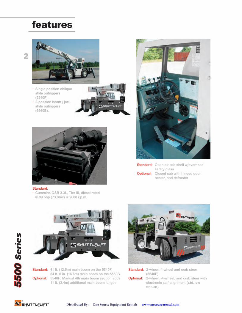
features• 2 models …
5540F: 15.0T (13.6mt) 3-section boom with 41 ft. 0 in. (12.5m) outreach
5560B: 18.0T (16.3mt) 4-section boom with 54 ft. 6 in. (16.6m) outreach
• 15 ft. (4.6m) offsettable swingaway extension
• 20,000 lb. (9 072kg) deck carrying capacity
• 101 bhp (75.3 kW) GM EFI dual fuel engine or 99 bhp (73.8 kW) Cummins,Tier III, diesel engine
Industrial Hydraulic Crane
contentsFeatures 2
Specifications 3
5540F
Dimensions 5Working Range 6Load Chart 8Load Chart 9
5560B
Dimensions 10Range Diagram 11Load Chart 12
www.manitowoc.com
2
features
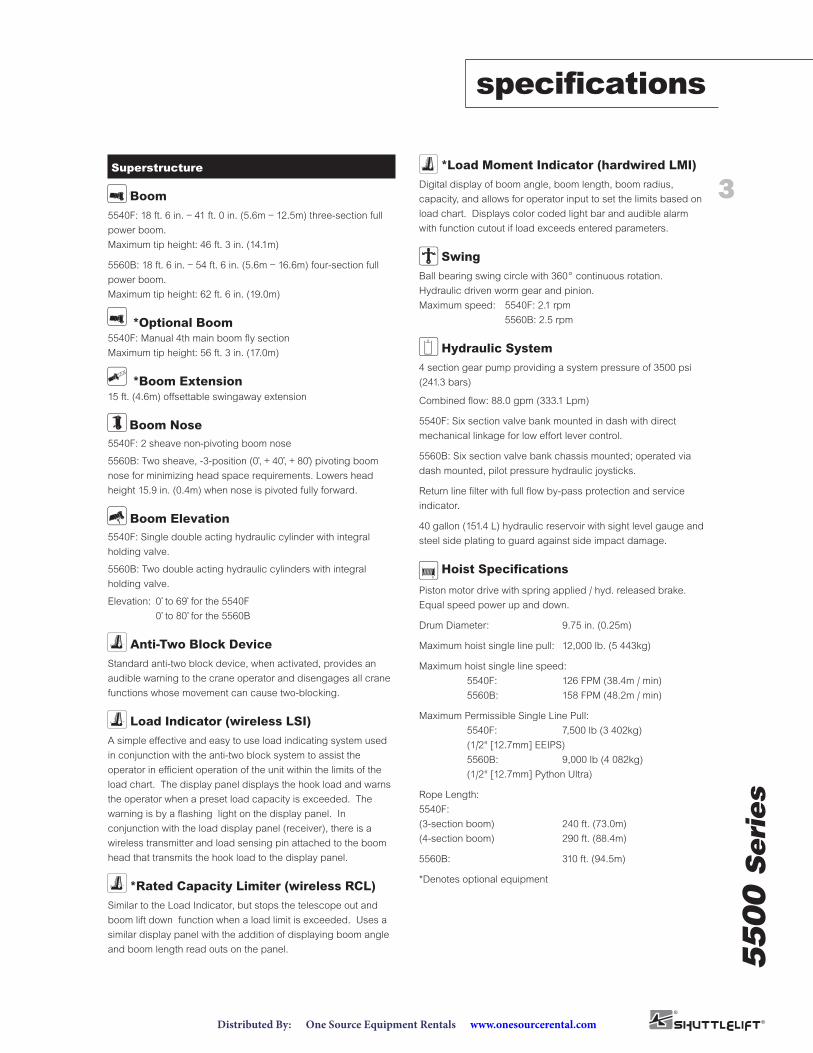
Standard: 41 ft. (12.5m) main boom on the 5540F54 ft. 6 in. (16.6m) main boom on the 5560B
Optional: 5540F: Manual 4th main boom section adds11 ft. (3.4m) additional main boom length
Standard: 2-wheel, 4-wheel and crab steer(5540F)
Optional: 2-wheel, -4-wheel, and crab steer withelectronic self-alignment (std. on5560B)
Standard: Open air cab shell w/overheadsafety glass
Optional: Closed cab with hinged door,heater, and defroster
Standard:• Cummins QSB 3.3L, Tier III, diesel rated
@ 99 bhp (73.8Kw) @ 2600 r.p.m.
• Single position obliquestyle outriggers(5540F).
• 2-position beam / jackstyle outriggers(5560B).
5500
Seri
es
5500
Seri
es
www.onesourcerental.comDistributed By: One Source Equipment Rentals
5500
Seri
es
3
specifications
Superstructure
Boom5540F: 18 ft. 6 in. – 41 ft. 0 in. (5.6m – 12.5m) three-section fullpower boom.Maximum tip height: 46 ft. 3 in. (14.1m)
5560B: 18 ft. 6 in. – 54 ft. 6 in. (5.6m – 16.6m) four-section fullpower boom.Maximum tip height: 62 ft. 6 in. (19.0m)
*Optional Boom5540F: Manual 4th main boom fly sectionMaximum tip height: 56 ft. 3 in. (17.0m)
*Boom Extension15 ft. (4.6m) offsettable swingaway extension
Boom Nose5540F: 2 sheave non-pivoting boom nose
5560B: Two sheave, -3-position (0˚, + 40˚, + 80˚) pivoting boomnose for minimizing head space requirements. Lowers headheight 15.9 in. (0.4m) when nose is pivoted fully forward.
Boom Elevation5540F: Single double acting hydraulic cylinder with integralholding valve.
5560B: Two double acting hydraulic cylinders with integralholding valve.
Elevation: 0 ˚ to 69˚ for the 5540F0 ˚ to 80 ˚ for the 5560B
Anti-Two Block DeviceStandard anti-two block device, when activated, provides anaudible warning to the crane operator and disengages all cranefunctions whose movement can cause two-blocking.
Load Indicator (wireless LSI)A simple effective and easy to use load indicating system usedin conjunction with the anti-two block system to assist theoperator in efficient operation of the unit within the limits of theload chart. The display panel displays the hook load and warnsthe operator when a preset load capacity is exceeded. Thewarning is by a flashing light on the display panel. Inconjunction with the load display panel (receiver), there is awireless transmitter and load sensing pin attached to the boomhead that transmits the hook load to the display panel.
*Rated Capacity Limiter (wireless RCL)Similar to the Load Indicator, but stops the telescope out andboom lift down function when a load limit is exceeded. Uses asimilar display panel with the addition of displaying boom angleand boom length read outs on the panel.
*Load Moment Indicator (hardwired LMI)Digital display of boom angle, boom length, boom radius,capacity, and allows for operator input to set the limits based onload chart. Displays color coded light bar and audible alarmwith function cutout if load exceeds entered parameters.
Swing Ball bearing swing circle with 360° continuous rotation. Hydraulic driven worm gear and pinion.Maximum speed: 5540F: 2.1 rpm
5560B: 2.5 rpm
Hydraulic System4 section gear pump providing a system pressure of 3500 psi(241.3 bars)
Combined flow: 88.0 gpm (333.1 Lpm)
5540F: Six section valve bank mounted in dash with directmechanical linkage for low effort lever control.
5560B: Six section valve bank chassis mounted; operated viadash mounted, pilot pressure hydraulic joysticks.
Return line filter with full flow by-pass protection and serviceindicator.
40 gallon (151.4 L) hydraulic reservoir with sight level gauge andsteel side plating to guard against side impact damage.
Hoist Specifications
Piston motor drive with spring applied / hyd. released brake.Equal speed power up and down.
Drum Diameter: 9.75 in. (0.25m)
Maximum hoist single line pull: 12,000 lb. (5 443kg)
Maximum hoist single line speed:5540F: 126 FPM (38.4m / min)5560B: 158 FPM (48.2m / min)
Maximum Permissible Single Line Pull:5540F: 7,500 lb (3 402kg)(1/`2" [12.7mm] EEIPS)5560B: 9,000 lb (4 082kg)(1/2" [12.7mm] Python Ultra)
Rope Length:5540F: (3-section boom) 240 ft. (73.0m)(4-section boom) 290 ft. (88.4m)
5560B: 310 ft. (94.5m)
*Denotes optional equipment
Boom
Boom
Extension
Boom Nose
Boom Elevation
Load Moment & Anti-Two Block System
Load Moment & Anti-Two Block System
Load Moment & Anti-Two Block System
Swing
Load Moment & Anti-Two Block System
Hydraulic System
Hoist
www.onesourcerental.comDistributed By: One Source Equipment Rentals
4
5500
Seri
es
specifications
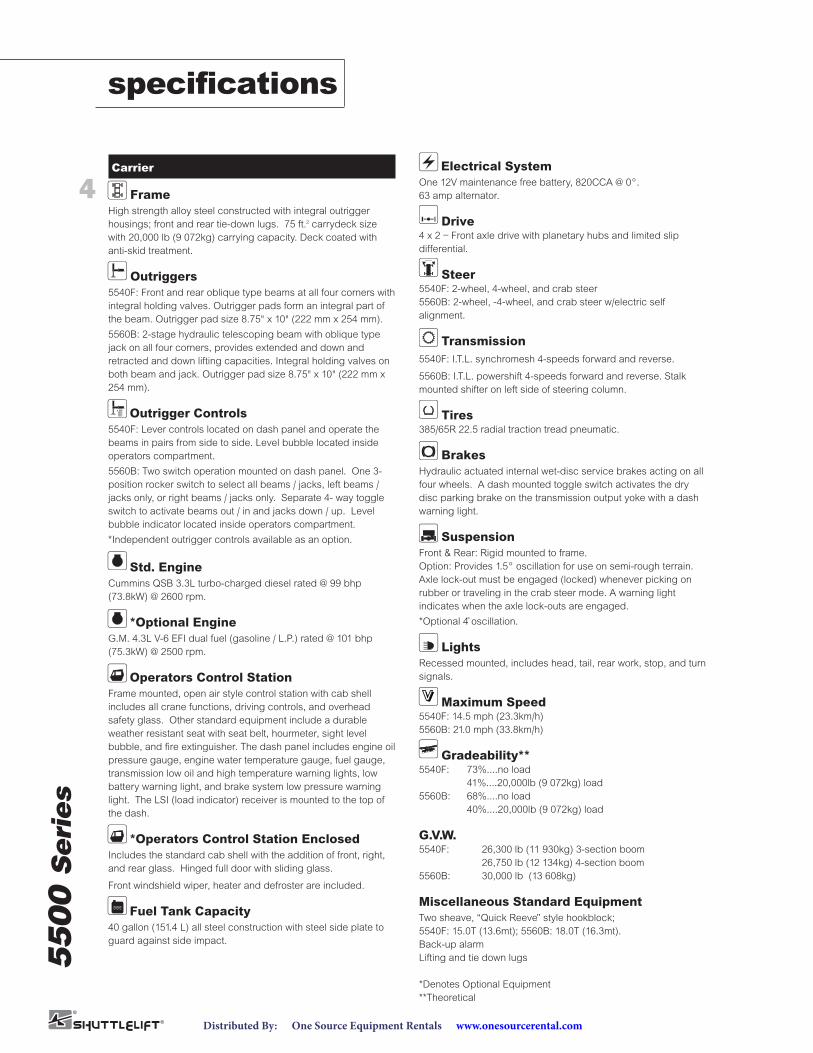
Carrier
FrameHigh strength alloy steel constructed with integral outriggerhousings; front and rear tie-down lugs. 75 ft.2 carrydeck sizewith 20,000 lb (9 072kg) carrying capacity. Deck coated withanti-skid treatment.
Outriggers5540F: Front and rear oblique type beams at all four corners withintegral holding valves. Outrigger pads form an integral part ofthe beam. Outrigger pad size 8.75" x 10" (222 mm x 254 mm).
5560B: 2-stage hydraulic telescoping beam with oblique typejack on all four corners, provides extended and down andretracted and down lifting capacities. Integral holding valves onboth beam and jack. Outrigger pad size 8.75" x 10" (222 mm x254 mm).
Outrigger Controls5540F: Lever controls located on dash panel and operate thebeams in pairs from side to side. Level bubble located insideoperators compartment.
5560B: Two switch operation mounted on dash panel. One 3-position rocker switch to select all beams / jacks, left beams /jacks only, or right beams / jacks only. Separate 4- way toggleswitch to activate beams out / in and jacks down / up. Levelbubble indicator located inside operators compartment.
*Independent outrigger controls available as an option.
Std. EngineCummins QSB 3.3L turbo-charged diesel rated @ 99 bhp(73.8kW) @ 2600 rpm.
*Optional EngineG.M. 4.3L V-6 EFI dual fuel (gasoline / L.P.) rated @ 101 bhp(75.3kW) @ 2500 rpm.
Operators Control StationFrame mounted, open air style control station with cab shellincludes all crane functions, driving controls, and overheadsafety glass. Other standard equipment include a durableweather resistant seat with seat belt, hourmeter, sight levelbubble, and fire extinguisher. The dash panel includes engine oilpressure gauge, engine water temperature gauge, fuel gauge,transmission low oil and high temperature warning lights, lowbattery warning light, and brake system low pressure warninglight. The LSI (load indicator) receiver is mounted to the top ofthe dash.
*Operators Control Station EnclosedIncludes the standard cab shell with the addition of front, right,and rear glass. Hinged full door with sliding glass.
Front windshield wiper, heater and defroster are included.
Fuel Tank Capacity40 gallon (151.4 L) all steel construction with steel side plate toguard against side impact.
Electrical SystemOne 12V maintenance free battery, 820CCA @ 0°. 63 amp alternator.
Drive4 x 2 – Front axle drive with planetary hubs and limited slipdifferential.
Steer5540F: 2-wheel, 4-wheel, and crab steer5560B: 2-wheel, -4-wheel, and crab steer w/electric selfalignment.
Transmission5540F: I.T.L. synchromesh 4-speeds forward and reverse.
5560B: I.T.L. powershift 4-speeds forward and reverse. Stalkmounted shifter on left side of steering column.
Tires385/65R 22.5 radial traction tread pneumatic.
BrakesHydraulic actuated internal wet-disc service brakes acting on allfour wheels. A dash mounted toggle switch activates the drydisc parking brake on the transmission output yoke with a dashwarning light.
SuspensionFront & Rear: Rigid mounted to frame.Option: Provides 1.5° oscillation for use on semi-rough terrain.Axle lock-out must be engaged (locked) whenever picking onrubber or traveling in the crab steer mode. A warning lightindicates when the axle lock-outs are engaged.
*Optional 4˚ oscillation.
LightsRecessed mounted, includes head, tail, rear work, stop, and turnsignals.
Maximum Speed5540F: 14.5 mph (23.3km/h)5560B: 21.0 mph (33.8km/h)
Gradeability**5540F: 73%....no load
41%....20,000lb (9 072kg) load5560B: 68%....no load
40%....20,000lb (9 072kg) load
G.V.W.5540F: 26,300 lb (11 930kg) 3-section boom
26,750 lb (12 134kg) 4-section boom5560B: 30,000 lb (13 608kg)
Miscellaneous Standard EquipmentTwo sheave, “Quick Reeve” style hookblock; 5540F: 15.0T (13.6mt); 5560B: 18.0T (16.3mt).Back-up alarmLifting and tie down lugs
*Denotes Optional Equipment**Theoretical
Frame
Outriggers
Outrigger Controls
Engine
Engine
Cab
Cab
Electrical System
Steering
Transmission
Drive
Tires
Brakes
Suspension
Lights
Speed
Grade
Fuel Tank Capacity
www.onesourcerental.comDistributed By: One Source Equipment Rentals
5
5500
Seri
es
5500
Seri
es
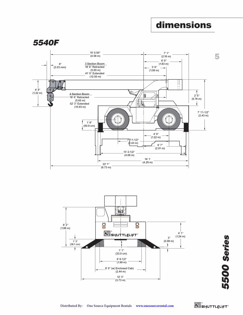
dimensions
15' 0.50"(4.58 m)
7' 1"(2.16 m)
6' 0"(1.83 m)
3' 6"(1.06 m)
2' 5"(0.74 m)
7' 11-1/2"(2.43 m)
4' 0"(1.22 m)
6' 7"(2.01 m)
13' 2-1/2''(4.06 m)
22' 1''(6.73 m)
1' 8"(50.8 cm)
14' 1'(4.29 m)
3 Section Boom18' 6'' Retracted
(5.65 m)41' 0" Extended
(12.50 m)
4' 4"(1.32 m)
7' 11-1/2"(2.43 m)
8"(2.03 mm)
3"(0.08 m)
8' 0" (w/ Enclosed Cab)(2.44 m)
12' 3"(3.73 m)
6' 2"(1.88 m)
6' 6-1/2"(1.99 m)
4' 1"(1.24 m)
1' 3"(38.1 cm)
1' 1"(33.0 cm)
4 Section Boom18' 6'' Retracted
(5.65 m)52' 3" Extended
(15.93 m)
YB5515 Dimensions
5540F
www.onesourcerental.comDistributed By: One Source Equipment Rentals
6
5500
Seri
es
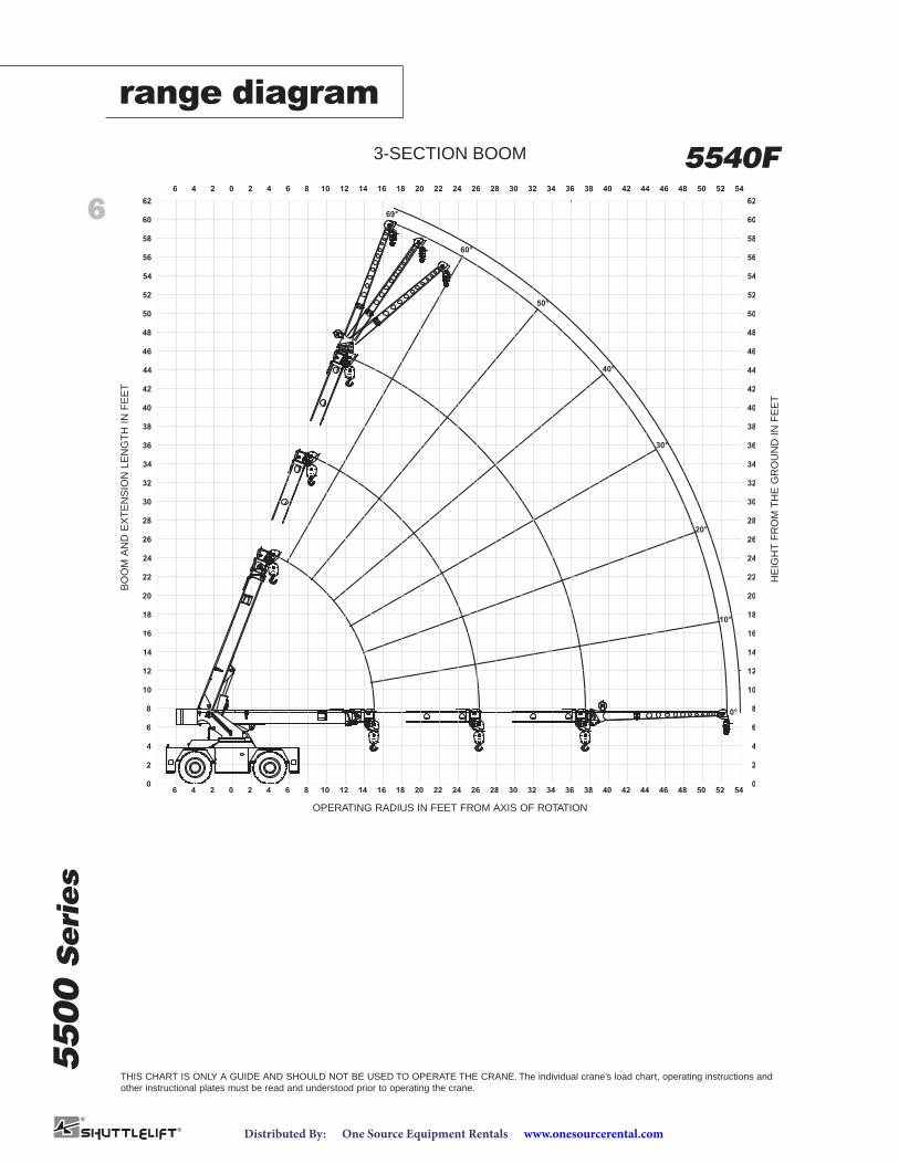
range diagram
3-SECTION BOOM 5540FB
OO
MA
ND
EX
TE
NS
ION
LEN
GT
HIN
FE
ET
OPERATING RADIUS IN FEET FROM AXIS OF ROTATION
HE
IGH
TF
RO
MT
HE
GR
OU
ND
INF
EE
T
THIS CHART IS ONLY A GUIDE AND SHOULD NOT BE USED TO OPERATE THE CRANE. The individual crane’s load chart, operating instructions andother instructional plates must be read and understood prior to operating the crane.
www.onesourcerental.comDistributed By: One Source Equipment Rentals
7
5500
Seri
es
5500
Seri
es
52
0
2
4
6
8
10
12
14
16
18
20
22
24
26
28
30
32
34
44
36
38
40
42
48
46
50
60
56
54
58
62
64
66
68
70
72
128 10 14 16 18 20 3822 24 26 28 3430 32 36 464240 44 48 50 52 54 56 58 60 62 64 660
46 4 2 0 2 6
46 4 2 0 2 1286 10 14 16 18 20 3822 24 26 28 3430 32 36 464240 44 48 50 52 54 56 58 60 62 64 66
52
2
4
6
8
10
12
14
16
18
20
22
24
26
28
30
32
34
44
36
38
40
42
48
46
50
60
56
54
58
62
64
66
68
70
72
0o
10o
20o
30o
40o
50o
60o
69o
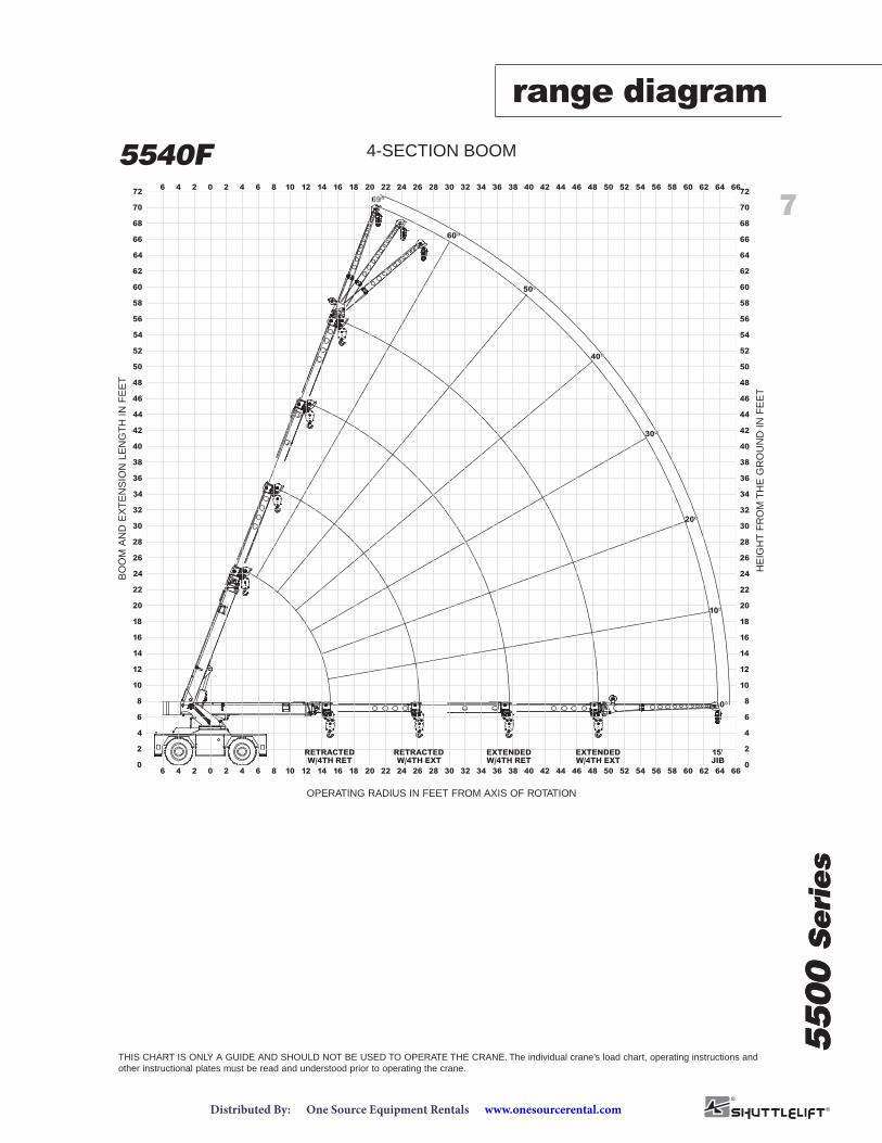
RETRACTEDW/4TH RET
RETRACTEDW/4TH EXT
EXTENDEDW/4TH RET
EXTENDEDW/4TH EXT
15'JIB
OPERA TING RADIUS IN FEET FROM AXIS OF ROT ATION
HE
IGH
TF
RO
MT
HE
GR
OU
ND
INF
EE
T
YB5515 (4-SECTION BOOM)4-SECTION BOOM5540FB
OO
MA
ND
EX
TE
NS
ION
LEN
GT
HIN
FE
ET
OPERATING RADIUS IN FEET FROM AXIS OF ROTATION
HE
IGH
TF
RO
MT
HE
GR
OU
ND
INF
EE
T
range diagram
THIS CHART IS ONLY A GUIDE AND SHOULD NOT BE USED TO OPERATE THE CRANE. The individual crane’s load chart, operating instructions andother instructional plates must be read and understood prior to operating the crane.
www.onesourcerental.comDistributed By: One Source Equipment Rentals
8
5500
Seri
es
0-30000 lbs
4-PART
0-7500 lbs
1-PART
RIGGING CHART
WIRE ROPE: 1/2 inch diameter
Min. breaking strength 26250 lbs.
REDUCTION CHART
MAIN BOOMFROM
RATINGS
JIB
FROM
RATINGS
MAIN BLOCK
HOOK & BALL
JIB, STOWED
JIB, DEPLOYED
210 lbs
100 lbs
0 lbs
700 lbs
N/A
100 lbs
N/A
0 lbs
SHADED AREAS ARE GOVERNED BY STRUCTURAL
OPERATION OF THIS EQUIPMENT IN EXCESS OF
JIB CAPACITY IS LIMITED BY BOTH STRUCTURAL
FRONT REAR
SIDE
SIDE
15°
30°
15°
30°
STRENGTH, DO NOT RELY ON TIPPING.
RATING CHARTS AND DISREGARD OF INSTRUCTIONS
IS DANGEROUS AND VOIDS WARRANTY.
CAPACITY CHART AND MAIN CAPACITY CHART.
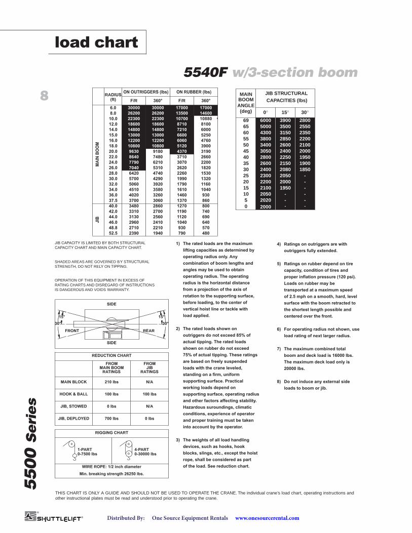
1) The rated loads are the maximum
lifting capacities as determined by
operating radius only. Any
combination of boom lengths and
angles may be used to obtain
operating radius. The operating
radius is the horizontal distance
from a projection of the axis of
rotation to the supporting surface,
before loading, to the center of
vertical hoist line or tackle with
load applied.
2) The rated loads shown on
outriggers do not exceed 85% of
actual tipping. The rated loads
shown on rubber do not exceed
75% of actual tipping. These ratings
are based on freely suspended
loads with the crane leveled,
standing on a firm, uniform
supporting surface. Practical
working loads depend on
supporting surface, operating radius
and other factors affecting stability.
Hazardous suroundings, climatic
conditions, experience of operator
and proper training must be taken
into account by the operator.
3) The weights of all load handling
devices, such as hooks, hook
blocks, slings, etc., except the hoist
rope, shall be considered as part
of the load. See reduction chart.
4) Ratings on outriggers are with
outriggers fully extended.
5) Ratings on rubber depend on tire
capacity, condition of tires and
proper inflation pressure (120 psi).
Loads on rubber may be
transported at a maximum speed
of 2.5 mph on a smooth, hard, level
surface with the boom retracted to
the shortest length possible and
centered over the front.
6) For operating radius not shown, use
load rating of next larger radius.
7) The maximum combined total
boom and deck load is 16000 lbs.
The maximum deck load only is
20000 lbs.
8) Do not induce any external side
loads to boom or jib.
YB5515 (3-SECTION BOOM)
ON OUTRIGGERS (lbs)M
AINBOOM
JIB
ON RUBBER (lbs)
14800
RADIUS
(ft)
13000
12200
10800
9630
8640
14800
13000
12200
10800
9180
4290
3260
3060
3580
3920
5310
4740
6210
7480
3480
3310
2960
2710
2410
2210
2700
2560
2860
5060
4020
4510
7040
6420
5700
7790
3700
7210
6600
6000
5250
640
570
740
690
3190
1320
930
860
800
1160
1040
1820
1530
2200
2660
4760
3900
1040
930
1190
1120
4370
1990
1460
1270
1370
1790
1610
2620
2260
3070
3710
6060
5120
3130
F/R 360° F/R 360°
30000
26200
22300
18600
30000
26200
22300
18600
17000
13500
17000
14600
10880
8100
10700
8710
14.0
15.0
16.0
18.0
20.0
22.0
24.0
26.0
28.0
30.0
32.0
34.0
36.0
37.5
40.0
42.0
44.0
46.0
48.8
6.0
8.0
10.0
12.0
2390 1940 48079052.5
BOOM
(deg)ANGLE
MAIN
60
40
15
0
3035
4550
2250
1950
-
21502080
3150
26002400
JIB STRUCTURAL
55 2850
25 205020 2000
5 -10 -
69 390065 3500
2800
2100
2000
26002400
4300
34003050
3800
23002200
20202050
60005000
1950
-
-
19001850
2350
21002000
2200
--
--
28002550
15°0° 30°
CAPACITIES (lbs)
THIS CHART IS ONLY A GUIDE AND SHOULD NOT BE USED TO OPERATE THE CRANE. The individual crane’s load chart, operating instructions andother instructional plates must be read and understood prior to operating the crane.
5540F w/3-section boom
load chart
www.onesourcerental.comDistributed By: One Source Equipment Rentals
9
5500
Seri
es
ON RUBBER (lbs)ON OUTRIGGERS (lbs)
MA
INB
OO
MJ
IB
1480014.0
RADIUS(ft)
15.0 13000
16.0 12200
18.0 10800
20.0 9630
22.0 8640
24.0
26.0
28.0
30.0
32.0
34.0
36.0
37.5
40.0
42.0
44.0
46.0
48.8
58.0
52.5
14800
13000
12200
10600
8630
4420
3190
2890
3570
3950
5700
5040
6460
7350
2950
2760
2430
2240
2030
- -
2090
1850
1480
2430
2250
2600
4400
3510
3930
6800
5820
5020
7790
3210
7210
6600
5480
4890
-
450
380
290
550
500
3080
1220
770
680
610
1070
920
1610
1410
1990
2460
4500
3750
-
800
680
500
970
890
3980
1880
1280
1070
1180
1650
1460
2360
2100
2720
3230
6060
4950
2590
F/R 360o F/R 360o
63.8 - - --
ON RUBBER (lbs)ON OUTRIGGERS (lbs)
8290
RADIUS(ft)
8200
8110
7950
7820
7710
8390
8200
8110
7950
7820
4760
3190
2970
3570
4080
6330
5420
7270
7710
3400
3150
2630
2320
2070
1720 1380
2130
1930
1710
2490
2300
2700
5180
4250
4680
7100
6590
5710
7630
3830
7760
7150
7500
6080
170
470
370
280
630
540
3560
1580
990
880
740
1360
1160
2150
1840
2520
3000
5510
4500
420
790
710
590
960
870
4730
2190
1370
1070
1240
1880
1600
2940
2550
3410
3980
6610
5680
2890
F/R 360o F/R 360o
1330 1020 60230
4TH EXTENDED
300006.0
8.0 26200
10.0 22300
12.0 18600
30000
26200
22300
18600
17000
13500
17000
14600
11000
7650
10700
8710
-
11000
10700
9250
-
11000
10700
9250
-
11000
-
11000
10700
9250
10700
9250
14.0
15.0
16.0
18.0
20.0
22.0
24.0
26.0
28.0
30.0
32.0
34.0
36.0
37.5
40.0
42.0
44.0
46.0
48.8
58.0
52.5
63.8
6.0
8.0
10.0
12.0
4TH RETRACTED
BOOM
(deg)
ANGLE
MAIN
4TH RETRACTED
60
40
15
0
30
35
45
50
2250
1950
-
2150
2080
3150
2600
2400
JIB STRUCTURAL CAPACITIES (lbs)
55 2850
25 2050
20 2000
5 -
10 -
69 3900
65 3500
4TH EXTENDED
2800
2100
2000
2600
2400
4300
3400
3050
3800
2300
2200
2020
2050
6000
5000
1950
-
-
1900
1850
2350
2100
2000
2200
-
-
-
-
2800
2550
15o0o 30o 0o 15o 30o
2250
1950
-
2150
2080
3150
2600
2400
2850
2050
2000
-
-
3900
3500
2800
2100
2000
2600
2400
4300
3400
3050
3800
2300
2200
2020
2050
5180
4970
1950
-
-
1900
1850
2350
2100
2000
2200
-
-
-
-
2800
2550
0-30000 lbs4-PART
0-7500 lbs1-PART
RIGGING CHART
WIRE ROPE: 1/2 inch diameter
Min. breaking strength 26250 lbs.
REDUCTION CHART
MAIN BOOMFROM
RATINGSJIB
FROM
RATINGS
MAIN BLOCK
HOOK & BALL
JIB, STOWED
JIB, DEPLOYED
210 lbs
100 lbs
0 lbs
700 lbs
N/A
100 lbs
N/A
0 lbs
SHADED AREAS ARE GOVERNED BY STRUCTURAL
OPERATION OF THIS EQUIPMENT IN EXCESS OF
JIB CAP ACITY IS LIMITED BY BOTH STRUCTURAL
FRONT REAR
SIDE
SIDE
15o
30o
15o
30o
STRENGTH, DO NOT RELY ON TIPPING.
RATING CHARTS AND DISREGARD OF INSTRUCTIONS
IS DANGEROUS AND VOIDS WARRANTY .
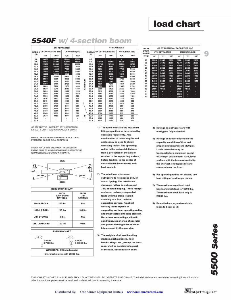
CAPACITY CHART AND MAIN CAPACITY CHART.1) The rated loads are the maximum
lifting capacities as determined by
operating radius only. Any
combination of boom lengths and
angles may be used to obtain
operating radius. The operating
radius is the horizontal distance
from a projection of the axis of
rotation to the supporting surface,
before loading, to the center of
vertical hoist line or tackle with
load applied.
2) The rated loads shown on
outriggers do not exceed 85% of
actual tipping. The rated loads
shown on rubber do not exceed
75% of actual tipping. These ratings
are based on freely suspended
loads with the crane leveled,
standing on a firm, uniform
supporting surface. Practical
working loads depend on
supporting surface, operating radius
and other factors affecting stability.
Hazardous suroundings, climatic
conditions, experience of operator
and proper training must be taken
into account by the operator.
3) The weights of all load handling
devices, such as hooks, hook
blocks, slings, etc., except the hoist
rope, shall be considered as part
of the load. See reduction chart.
4) Ratings on outriggers are with
outriggers fully extended.
5) Ratings on rubber depend on tire
capacity, condition of tires and
proper inflation pressure (120 psi).
Loads on rubber may be
transported at a maximum speed
of 2.5 mph on a smooth, hard, level
surface with the boom retracted to
the shortest length possible and
centered over the front.
6) For operating radius not shown, use
load rating of next larger radius.
7) The maximum combined total
boom and deck load is 16000 lbs.
The maximum deck load only is
20000 lbs.
8) Do not induce any external side
loads to boom or jib.
THIS CHART IS ONLY A GUIDE AND SHOULD NOT BE USED TO OPERATE THE CRANE. The individual crane’s load chart, operating instructions andother instructional plates must be read and understood prior to operating the crane.
5540F w/ 4-section boom
5500
Seri
es
load chart
www.onesourcerental.comDistributed By: One Source Equipment Rentals
dimensions
10
5500
Seri
es
THIS CHART IS ONLY A GUIDE AND SHOULD NOT BE USED TO OPERATE THE CRANE. The individual crane’s load chart, operating instructions andother instructional plates must be read and understood prior to operating the crane.
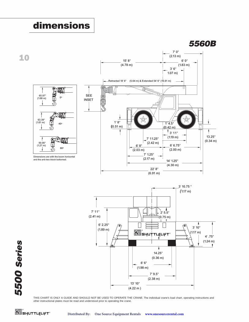
7' 11"(2.41 m)
6' 2.25"(1.89 m)
3' 10"(1.17 m)
14.25"(0.36 m)
6' 6"(1.98 m)
7' 9.5"(2.38 m)
13' 10"(4.22 m )
4' .75"(1.24 m)
2' 5.5"(0.75 m)
3' 10.75 "(1.17 m)
6' 8"(2.03 m)
1' 4.5"(0.42 m)
3' 6"1.07 m)
15' 8"(4.78 m)
SEEINSET
1' 8"(0.51 m)
3' 11"(1.19 m)7' 11.25"
(2.42 m)6' 6.75"(2.00 m)
7' 1.25"(2.17 m)
14' 1.25"(4.30 m)
22' 8"(6.91 m)
13.25"(0.34 m)
Retracted 18' 6" (5.64 m) & Extended 54' 6" (16.61 m)
6' 0"(1.83 m)
7' 0"(2.13 m)
(1.68 m)65.97"
0o
(1.61 m)63.39"
40o
(1.27 m)50.00"
80o
YB5518 Dimensions
Dimensions are with the boom horizontaland the anti-two block bottomed.
7' 11"(2.41 m)
6' 2.25"(1.89 m)
3' 10"(1.17 m)
14.25"(0.36 m)
6' 6"(1.98 m)
7' 9.5"(2.38 m)
13' 10"(4.22 m )
4' .75"(1.24 m)
2' 5.5"(0.75 m)
3' 10.75 "(1.17 m)
6' 8"(2.03 m)
1' 4.5"(0.42 m)
1' 8"(0.51 m)
3' 11"(1.19 m)7' 11.25"
(2.42 m)6' 6.75"(2.00 m)
7' 1.25"(2.17 m)
14' 1.25"(4.30 m)
22' 8"(6.91 m)
13.25"(0.34 m)
(1.68 m)65.97"
0o
(1.61 m)63.39"
40o
(1.27 m)50.00"
80o
Dimensions are with the boom horizontaland the anti-two block bottomed.
7' 11"(2.41 m)
6' 2.25"(1.89 m)
3' 10"(1.17 m)
14.25"(0.36 m)
6' 6"(1.98 m)
7' 9.5"(2.38 m)
13' 10"(4.22 m )
4' .75"(1.24 m)
2' 5.5"(0.75 m)
3' 10.75 "(1.17 m)
6' 8"(2.03 m)
1' 4.5"(0.42 m)
3' 6"1.07 m)
15' 8"(4.78 m)
SEEINSET
1' 8"(0.51 m)
3' 11"(1.19 m)7' 11.25"
(2.42 m)6' 6.75"(2.00 m)
7' 1.25"(2.17 m)
14' 1.25"(4.30 m)
22' 8"(6.91 m)
13.25"(0.34 m)
Retracted 18' 6" (5.64 m) & Extended 54' 6" (16.61 m)
6' 0"(1.83 m)
7' 0"(2.13 m)
(1.68 m)65.97"
0o
(1.61 m)63.39"
40o
(1.27 m)50.00"
80o
YB5518 Dimensions
Dimensions are with the boom horizontaland the anti-two block bottomed.
5560B
www.onesourcerental.comDistributed By: One Source Equipment Rentals
11
5500
Seri
es
8
0o
75o80o
MO
OB
TF
5.81
MO
OB
TF
5.03
MO
OB
TF
5.24
MO
OB
TF
5.45
686 4 2 0 2 4 6 8 10 66646260585654525048464442403836343230282624222018161412
784008 6 4 2 20102 4 6 8 12 14 16 18 3022 24 2826 32 34 3836 605042 44 4846 52 54 5856 62 64 6866
76
74
72
70
68
66
64
62
60
58
56
54
52
50
48
46
44
42
40
38
36
34
32
30
28
26
24
22
20
18
16
14
12
10
8
6
4
2
0
14
0
2
4
6
8
10
12
16
18
20
22
24
26
30
28
32
34
36
38
46
40
42
44
48
50
52
54
56
58
62
60
64
78
66
68
70
72
74
76
70o
65o
60o
55o
50o
45o
40o
35o
30o
25o
20o
15o
10o
5o
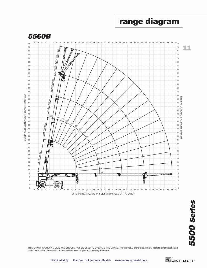
YB5518 Range Diagram
69.5
FT
WIT
H15
FT
JIB
THIS CHART IS ONLY A GUIDE AND SHOULD NOT BE USED TO OPERATE THE CRANE. The individual crane’s load chart, operating instructions andother instructional plates must be read and understood prior to operating the crane.
5560B
5500
Seri
es
range diagramB
OO
MA
ND
EX
TE
NS
ION
LEN
GT
HIN
FE
ET
OPERATING RADIUS IN FEET FROM AXIS OF ROTATION
HE
IGH
TF
RO
MT
HE
GR
OU
ND
INF
EE
T
www.onesourcerental.comDistributed By: One Source Equipment Rentals
12
5500
Seri
es
THIS CHART IS ONLY A GUIDE AND SHOULD NOT BE USED TO OPERATE THE CRANE. The individual crane’s load chart, operating instructions andother instructional plates must be read and understood prior to operating the crane.
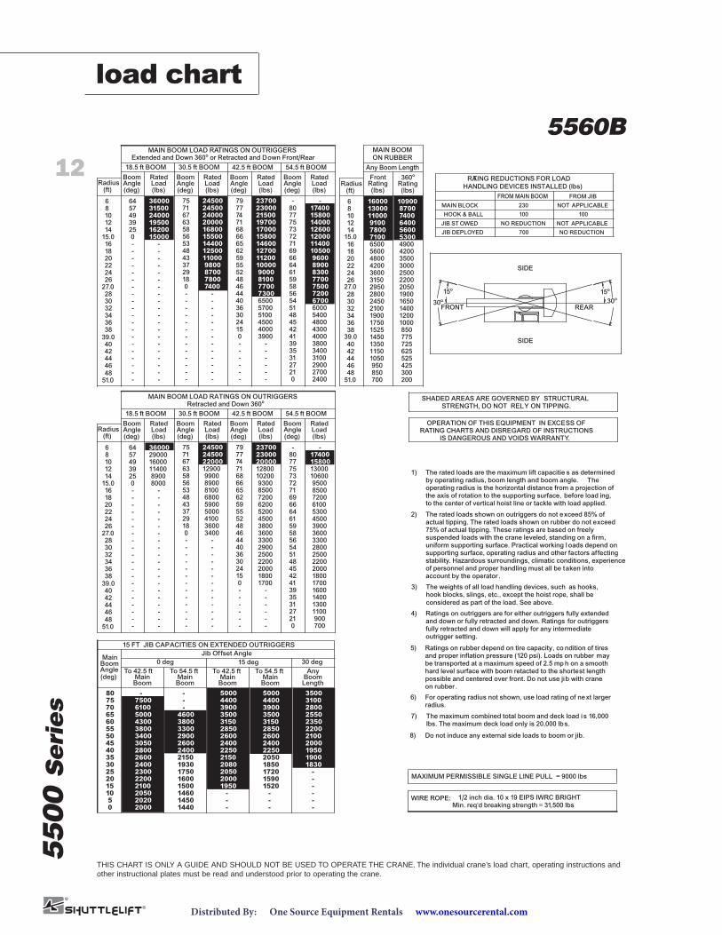
40
Any Boom Length
86
10
14
16182022
26
28303234
38
(ft)
36
24
12
Radius Rating(lbs)
10900
360o
4039.0383634
2426
27.02830
(ft)
1415.0161820
1086
Radius(lbs)(deg)
18.5 ft BOOM
RatedLoad
BoomAngle
30.5 ft BOOM
MAIN BOOM LOAD RATINGS ON OUTRIGGERSExtended and Down 360o or Retracted and Down Front/Rear
RatedLoad(lbs)
BoomAngle(deg)
42.5 ft BOOM
BoomAngle(deg)
RatedLoad(lbs)
54.5 ft BOOM
RatedLoad(lbs)(deg)
AngleBoom
Retracted and Down 360oMAIN BOOM LOAD RATINGS ON OUTRIGGERS
42.5 ft BOOM
(deg)AngleBoom
Radius(ft) (deg) (lbs)(lbs)(deg)
18.5 ft BOOM
AngleBoom Rated
Load
30.5 ft BOOM
AngleBoom
LoadRated
(deg) (lbs)(lbs)
54.5 ft BOOM
BoomAngleLoad
RatedLoadRated
16000
(lbs)RatingFront
MAIN BOOMON RUBBER
42
4648
44
51.0
12
22
32
64 36000 75 24500 2370079 --
51.0
39.0383634323028
4846444240
27.0
15.0
22
2624
12
201816
14
6
108
48464442
57 31500 71 24500 77 8023000 17400
49 24000 67 24000 74 7721500 15800
39 19500 63 20000 71 7519700 14000
25 16200 58 16800 68 7317000 12600
0 15000 56 15500 66 7215800 12000
- - 53 14400 65 7114600 11400
- - 48 12500 62 6912700 10500
- - 43 11000 59 6611200 9600
- - 37 9800 55 6410000 8900
- - 29 8700 52 619000 8300
- - 18 7800 48 598100 7700
- - 0 7400 46 587700 7500
- - - - 44 567300 7200
- - - - 40 546500 6700
- - - - 36 515700 6000- - - - 30 485100 5400- - - - 24 454500 4800- - - - 15 424000 4300- - - - 0 413900 4000- - - - - 39- 3800- - - - - 35- 3400- - - - - 31- 3100- - - - - 27- 2900- - - - - 21- 2700- - - - - 0- 2400
--
--
--
--
------
------
-----
-----
15
------
---
0-
-----
36
2430
4044
7467
48
-----
29180
3743
--
80008900
1140016000
53565863
62
34003600410050005900
52
4648
5559
6800810089009900
1290022000
65666871
2900036000
71 24500
24500
77
27
021
--
700900
42
31353941
----
1700
110013001400160017001800
4548515456
18002000220025002900
20002200250028003300
77
69
5859616466
33003600380045005200
36003900450053006100
71727375
62007200
9300102001280020000
720085009500
106001300015800
80-
23000
23700
17400
-75 79
-------------
49
-----
0
--
2539
5764
8500
13000 8700
11000 7400
9100 6400
7800 5600
6500 49005600 42004800 35004200 30003600 25003150 2200
2800 19002450 16502100 14001900 12001750 10001525 850
1350 7251150 6251050 525
425300200
95085070051.0
39.0 1450 775
27.0 2950 2050
15.0 7100 5300
HANDLING DEVICES INSTALLED (lbs)
HOOK & BALL
MAIN BLOCK
FROM MAIN BOOM FROM JIB
RATING REDUCTIONS FOR LOAD
JIB ST OWED
JIB DEPLOYED
230
100
NO REDUCTION
700
NOT APPLICABLE
100
NOT APPLICABLE
NO REDUCTION
15o
30o
SIDE
FRONT REAR
15o
30o
SIDE
1/2 inch dia. 10 x 19 EIPS IWRC BRIGHTMin. req'd breaking strength = 31,500 lbs
WIRE ROPE:
MAXIMUM PERMISSIBLE SINGLE LINE PULL = 9000 lbs
SHADED AREAS ARE GOVERNED BY STRUCTURALSTRENGTH, DO NOT RELY ON TIPPING.
OPERATION OF THIS EQUIPMENT IN EXCESS OFRATING CHARTS AND DISREGARD OF INSTRUCTIONS
IS DANGEROUS AND VOIDS WARRANTY.
15 FT JIB CAPACITIES ON EXTENDED OUTRIGGERS
Jib Offset Angle
205010
5
0 2000
2020
35
20
15
30
25
50
45
40
60
55
2600
2100
2200
2300
2400
2800
3050
3400
3800
4300
MainBoom
75
70
65
80
0 deg
5000
-
-
--
-
-
-
-
-
1900
1830
2100
1950
2000
2200
2350
2150
2000
1950
-
2080
2050
2600
2400
2250
3150
2850
30 deg
3100
2550
2800
3500
4400
3900
3500
15 deg
5000
2600
1600
1450
1440
1460
1500
1750
1930
2150
2400
3800
2900
3300
4600
6100
7500
-
To 42.5 ft To 54.5 ftAngleMain Main(deg) Boom
Any
-
-
Boom Boom Length
5000
3500
3900
2850
3150
4400
2250
2400
1720
1850
2050
1520
1590
2600
-
-
-
MainBoom
To 54.5 ftMainBoom
To 42.5 ftbe transported at a maximum speed of 2.5 mp h on a smooth
Do not induce any external side loads to boom or jib.
The maximum combined total boom and deck load is 16,000
For operating radius not shown, use load rating of next larger
possible and centered over front. Do not use jib with cranehard level surface with boom retacted to the shortest length
lbs. The maximum deck load only is 20,000 lbs.
radius.
on rubber .
7)
8)
6)
hook blocks, slings, etc., except the hoist rope, shall beThe weights of all load handling devices, such as hooks,
and proper inflation pressure (120 psi). Loads on rubber mayRatings on rubber depend on tire capacity, co ndition of tires
fully retracted and down will apply for any intermediateand down or fully retracted and down. Ratings for outriggersRatings on outriggers are for either outriggers fully extended
of personnel and proper handling must all be taken intostability. Hazardous surroundings, climatic conditions, experiencesupporting surface, operating radius and other factors affectinguniform supporting surface. Practical working l oads depend onsuspended loads with the crane leveled, standing on a firm,75% of actual tipping. These ratings are based on freelyactual tipping. The rated loads shown on rubber do not exceedThe rated loads shown on outriggers do not exceed 85% of
to the center of vertical hoist line or tackle with load applied.the axis of rotation to the supporting surface, before load ing,operating radius is the horizontal distance from a projection ofby operating radius, boom length and boom angle. TheThe rated loads are the maximum lift capacitie s as determined
2)
considered as part of the load. See above.
account by the operator .
3)
outrigger setting.
5)
4)
1)
load chart
5560B
www.onesourcerental.comDistributed By: One Source Equipment Rentals

13
5500
Seri
es
notes

14
5500
Seri
es
notes

15
notes
5500
Seri
es
5500
Seri
es
Constant improvement and engineering progressmake it necessary that we reserve the right to makespecification, equipment and price changes withoutnotice. Illustrations shown may include optionalequipment and accessories, and may not include allstandard equipment.
©2008 MANITOWOCPrinted in USA Form No. 5500 Series Part No. 07-009 / 0808 / 1M
AmericasBrazilAlphavilleTel: +55 11 3103 0200Fax: +55 11 4688 2013
MexicoMonterreyTel: +52 81 8124 0128Fax: +52 81 8124 0129
Europe, Middle East, AfricaAlgeriaHydraTel: +21 3 21 48 1173Fax: +21 3 21 48 1454
Czech RepublicNetvoriceTel: +420 317 78 9313Fax: +420 317 78 9314
FranceBaudemontTel: +33 385 28 2589Fax: +33 385 28 0430
CergyTel: +33 130 31 3150Fax: +33 130 38 6085
DecinesTel: +33 472 81 5000Fax: +33 472 81 5010
GermanyLangenfeldTel: +49 21 73 8909-0Fax: +49 21 73 8909 30
HungaryBudapestTel: +36 13 39 8622Fax: +36 13 39 8622
ItalyParabiagoTel: +390 331 49 3311Fax: +390 331 49 3330
NetherlandsBredaTel: +31 76 578 3999 Fax: +31 76 578 3978
PolandWarsawTel: +48 22 843 3824Fax: +48 22 843 3471
PortugalAlfenaTel: +351 229 69 8840Fax: +351 229 69 8848
LisbonTel: +351 212 109 340Fax: +351 212 109 349
RussiaMoscowTel: +7 495 641 2359Fax: +7 495 641 2358
U.A.E.DubaiTel: +971 4 3381 861Fax: +971 4 3382 343
U. K.MiddlesexTel: +44 1 895 43 0053Fax: +44 1 895 45 9500
SunderlandTel: +44 191 522 2000Fax: +44 191 522 2052
Asia – PacificAustraliaBrisbane38 Suscatand StreetRocklea Queensland 4106Tel: +617 3274 5879Fax: +617 3274 6558
Melbourne1/46 Venture DriveSunshine West VIC 3020Tel: +(03) 9336 1322Fax: +(03) 9336 1300
Sydney142 Magowar RoadGirraween, NSW 2145Tel: +61 02 9896 4433Fax: +61 02 9896 3122
ChinaBeijingTel: +86 10 58674761Fax: +86 10 58674760
Xi’anTel: +86 29 87891465Fax: +86 29 87884504
KoreaSeoulTel: +82 2 3439 0400Fax: +82 2 3439 0405
PhilippinesMakati CityTel: +63 2 844 9437Fax: +63 2 844 4712
Factories
BrazilAlphaville
ChinaZhangjiagang
FranceCharlieuLa ClayetteMoulins
GermanyWilhelmshaven
IndiaCalcuttaPune
ItalyNiella Tanaro
PortugalBaltarFânzeres
SlovakiaSaris
U.S.A.ManitowocPort WashingtonShady Grove
Regional Offices
AmericasManitowoc, Wisconsin, USATel: +1 920 684 6621Fax: +1 920 683 6278
Shady Grove, Pennsylvania, USATel: +1 717 597 8121Fax: +1 717 597 4062
Europe, Middle East, AfricaEcully, FranceTel: +33 472 18 2020Fax: +33 472 18 2000
Asia – PacificShanghai, ChinaTel: +86 21 51113579Fax: +86 21 51113578
SingaporeTel: +65 6264 1188Fax: +65 6862 4142
Regional Headquarters
www.manitowoc.com www.onesourcerental.com
Distributed By: