Embed Size (px)
Citation preview
Features
• CD3330F: 7,7 t (8.5 USt) three-section boom with 7,6 m (25 ft 2 in) tip height
• CD3330FL: 7,7 t (8.5 USt) three-section boom with 10,2 m (33 ft 6 in) tip height
• CD3339: 8,1 t (9 USt) three-section boom with 11,6 m (38 ft 2 in) tip height
• CD3340B: 9,5 t (10.5 USt) three-section boom with 11,6 m (38 ft 2 in) tip height
• 1,8 m (6 ft) fixed extension (CD3330F/CD3330FL) and 3,6 m (12 ft) offsettable swingaway extension (CD3339 and CD3340B)
• 74,5 kW (100 bhp) Tier IV Cummins diesel engine or 59,6 kW (80 bhp) GM EFI dual fuel engine
Shuttlelift CD3300 SeriesProduct Guide
Features
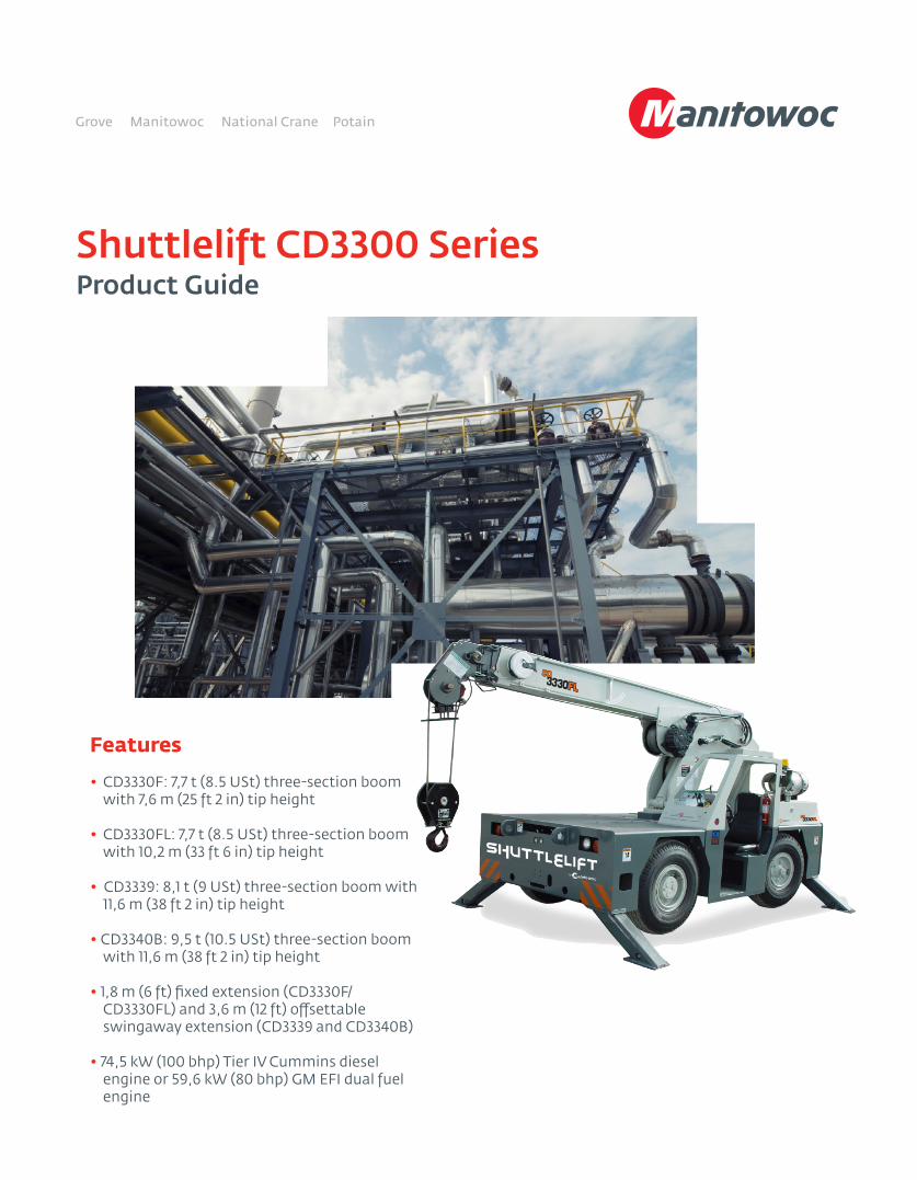
BoomStandard: 6,4 m (21 ft) main boom on the CD3330F.9,1 m (30 ft) main boom on the CD3330FL.10,0 m (32 ft 10 in) main boom on the CD3339 and CD3340B.Optional: Manual fourth main boom section adds 3,0 m (10 ft) additional main boom length on CD3330F and CD3330FL only.
Steering Standard: Two-wheel, four-wheel, and crab steer with electronic self alignment (CD3340B).Standard: Two-wheel, four-wheel, and crab steer on other CD3300 Series models.Optional: Electronic self-alignment on other CD3300 Series models.
CabStandard: Open air cab shell with overhead safety glass.Optional: Closed cab with split hinged door, heater/defroster, and all window glass.
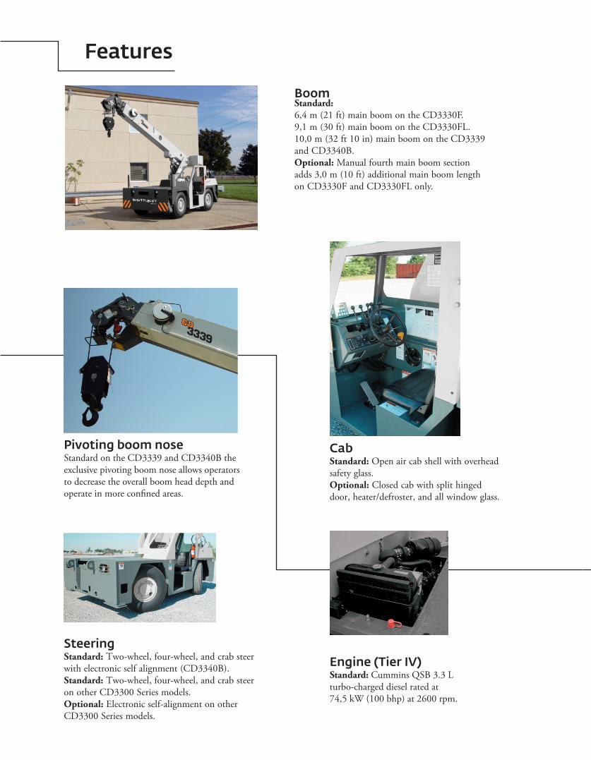
Pivoting boom noseStandard on the CD3339 and CD3340B the exclusive pivoting boom nose allows operators to decrease the overall boom head depth and operate in more confined areas.
Engine (Tier IV)Standard: Cummins QSB 3.3 L turbo-charged diesel rated at 74,5 kW (100 bhp) at 2600 rpm.
Contents
Specifications 4
CD3330F (dimensions/range diagram/load chart) 7
CD3330FL (dimensions/range diagram/load chart) 10
CD3339 (dimensions/range diagram/load chart) 15
CD3340B (dimensions/range diagram/load chart) 18
Symbols glossary 21
4
Specifications
*Denotes optional equipment
Superstructure
Boom
CD3330F: 2,9 m – 6,5 m (9 ft 8 in – 21 ft 2 in) three- section full power boom.Maximum tip height: 7,6 m (25 ft 2 in)CD3330FL: 3,8 m – 9,2 m (12 ft 8 in – 30 ft 2 in) three- section full power boom.Maximum tip height: 10,2 m (33 ft 6 in)CD3339 and CD3340B: 4,2 m – 10,0 m (13 ft 10 in – 32 ft 10 in) three-section full power boom. Maximum tip height: 11,6 m (38 ft 2 in)
*Optional boom
CD3330F and CD3330FL: Manual fourth main boom fly section adds 3,0 m (10 ft) additional boom length.
*Boom extension
CD3330F and CD3330FL: 1,8 m (6 ft) fixed pin on extensionCD3339 and CD3340B: 3,6 m (12 ft) offsettable extension. 3,6 m - 5,4 m (12 ft - 18 ft) telescopic offsettable extension
Boom nose
CD3330F and CD3330FL: Single sheave non-pivoting CD3339 and CD3340B: Single sheave, three-position (0˚, + 30˚, + 80˚) pivoting boom nose for minimizing head space requirements. Lowers head height. 0,26 m (10.5 in) when nose is pivoted fully forward.
Boom elevation
Single double acting hydraulic cylinder with integral holding valve.Elevation: 0° to 60° for the CD3330F / FL. 0° to 72° for the CD3339 and CD3340B
Anti-two block device
Standard anti-two block device, when activated, provides an audible warning to the crane operator and disengages all crane functions whose movement can cause two-blocking.
Load indicator (wireless LSI)
A simple, effective, and easy to use load indicating system used in conjunction with the anti-two block system to assist the operator in efficient operation of the unit within the limits of the load chart. The display panel displays the hook load and warns the operator when a preset load capacity is exceeded. The warning is by a flashing light on the display panel. In conjunction with the load display panel (receiver), there is a wireless transmitter and load sensing pin attached to the boom head that transmits the hook load to the display panel.
*Load Moment Indicator (hardwired LMI)
Digital display of boom angle, boom length, boom radius, capacity, and allows for operator in-put to set the limits based on load chart. Displays color coded light bar and audible alarm with function cutout if load exceeds entered parameters.
Swing
Ball bearing swing circle with 360° continuous rotation. Hydraulic driven worm gear and pinion.Maximum speed: 2.05 rpm
Hydraulic system
CD3330F / FL: (2) gear pumpsCD3339 and CD3340B: Variable displacement piston pump and piggyback gear pump.Combined flow: 107,9 Lpm (28.5 gpm)Maximum system operating pressure: 3600 psiCD3330F/FL and CD3339: Six section valve bank mounted in dash panel with direct mechanical linkage for low effort lever control.CD3340B: Six section valve bank chassis mounted; operated via dash mounted, pilot pressure hydraulic joysticks.Return line filter with full flow by-pass protection and service indicator.170 L (45 gal) hydraulic reservoir with sight level gauge and steel side plating to guard against side impact damage.
Shuttlelift CD3300 Series 5
Specifications
*Denotes optional equipment
Frame
Carrier
High strength alloy steel constructed with integral outrigger housings; front and rear lifting, towing, and tie-down lugs. 38 ft2 carrydeck size with 6350 kg (14,000 lb) carrying capacity (CD3330F, CD3330FL and CD3339) and 7711 kg (17,000 lb) carrying capacity (CD3340B). Deck coated with anti-skid treatment.
Outriggers
CD3330F, CD3330FL and CD3339: Front and rear oblique type beams at all four corners with integral holding valves. Outrigger pads form an integral part of the beam.CD3340B: Hydraulic telescoping beam with oblique type jack provides extended and down and retracted and down lifting capacities. Integral holding valves on both beam and jack.Padsize CD3300 Series: 18 cm x 20 cm (7.4 in x 7.8 in) Maximum outrigger pad load: CD3300F/FL: 122 psi CD3339: 135 psi CD3340B: 387 psi
Outrigger controls
CD3330F, CD3330FL: Lever controls located on dash panel which operate the beams in pairs from side to side.*Independent outrigger controls available as an option.
CD3339: Lever controls located on dash panel which operate the beams independently.
CD3340B: Two switch operation mounted on dash panel. One -three- position rocker switch to select individual beams or jacks. Separate -four- way toggle switch to activate beams out/in and jacks down/up. Level bubble indicator located inside operators compartment.
Standard engine (Tier III)
Cummins QSB 3.3 L turbo-charged diesel rated at 63,4 kW (85 bhp) at 2600 rpm. Supplied with 120 V engine block heater and air intake grid heater.
*Optional engine
G.M. 3.0 L EFI dual fuel (gasoline / L.P.) rated at 59,6 kW (80 bhp) at 2600 rpm.
Operators control station
Frame mounted, open air style control station with cab shell. Includes all crane functions, driving controls, and overhead safety glass. Other standard equipment include a durable weather resistant seat with seat belt, hourmeter, sight level bubble, and fire extinguisher. The dash panel includes engine oil pressure gauge, engine water temperature gauge, fuel gauge, transmission low oil and high temperature warning lights, low battery warning light, and brake system low pressure warning light.
Hoist specifications
CD3330F / FL: Worm drive with counter-balance valving. Equal speed power up and down.CD3339 and CD3340B: Piston motor drive with spring applied/hydraulic released brake.Drum diameter: CD3330F / FL: 0,24 m (9.69 in) CD3339 and CD3340B: 0,27 m (10.63 in)Maximum single line pull: CD3330F / FL: 4854 kg (10,700 lb) CD3339 and CD3340B: 6350 kg (14,000 lb)Maximum single line speed: CD3330F / FL: 26,8 m/min (88 fpm) CD3339 and CD3340B: 36,6 m/min (120 fpm)Maximum permissible single line pull: CD3330F / FL: 3855 kg (8,500 lb) (12,7 mm [1/2 inch] Python Ultra XIPS) CD3339 and CD3340B: 4536 kg (10,000 lb) (14,0 mm [9/16 inch] EEIPS)Rope length :CD3330F / FL: (three-section boom): 29,6 m (97 ft)(four-section boom): 39,6 m (130 ft)CD3339 and CD3340B: 36,6 m (120 ft)
Superstructure continued
Engine (Tier IV)
Cummins QSB 3.3 L, four-cylinder, turbo-charged diesel rated at 74.5 Kw (100 hp) at 2600 rpm. Standard 120 V engine block heater and cold weather intake grid heater.Diesel oxidation/catalyst, stainless steel muffler/exhaust system to meet 2012 EPA emissions, combined with a Cummins direct air flow, two-stage cyclonic air filter system.Maximum torque: 413,5 Nm (305 lb ft)Note: Required for sale in North American and European Union countries.
6
Specifications
Gross vehicle weight (G.V.W.)
CD3330F: 7231 kg (15,941 lb)CD3330FL: 7855 kg (17,318 lb)CD3339: 8021 kg (17,683 lb)CD3340B: 8312 kg (18,324 lb)*All weights with enclosed cab and Tier IV engine
Miscellaneous standard equipment
Single sheave, “Quick Reeve” style hook block.; CD3330F and CD3330FL: 8,0 t (8.5 USt) CD3339 and CD3340B: 10 t (10.5 USt) Back-up alarm
*Denotes optional equipment
Fuel tank capacity
64 L (17 gallon) all steel construction with steel side plate to guard against side impact.
Electrical system
One 12V maintenance free battery, 820CCA at 0°. Jump start connections.120 amp alternator.
Drive
4 x 2 – Front axle drive with planetary hubs and limited slip differential.
Steer
CD3330F/FL/ CD3339: two-wheel, four-wheel withcrab steerCD3340B: two-wheel, four-wheel, and crab steer with electronic self alignment.
Transmission
CD3330F, CD3330FL, CD3339: Synchromesh -four- speeds forward and reverse with stalk mounted forward/reverse selector.
CD3340B: Powershift -four- speeds forward andreverse. Stalk mounted shifter on left side of steeringcolumn.
Tires
10.00 x 15 pneumatic
Brakes
Hydraulic actuated internal wet-disc service brakes acting on all four wheels. A dash mounted toggle switch activates the dry disc parking brake on the transmission output yoke with a dash warning light.
Suspension
Front: Rigid mounted to frame.Rear: Rigid mounted to frame.
Lights
Recessed mounted, includes head, tail, rear work, stop, and turn signals.
35,6 km/h (22 mph)
Maximum speed
Gradeability (theoretical)
CD3330F, CD3330FL, CD3339: 57%....no load 31%.... 5443 kg (12,000 lb) load
CD3340B: 68%....no load 40%.... 9072 kg (20,000 lb) load
Axles
Front: Carraro planetary drive/steer with internal multi-wet-disc brakes and limited slip differential.Rear: Fabricated non-drive steer with disc brakes
*Operators control station enclosed
Includes the standard cab shell with the addition of front, right, and rear glass, a split (two-piece) hinged door with sliding glass. Front windshield wiper and heater and defroster is included.
Carrier continued
Shuttlelift CD3300 Series 7
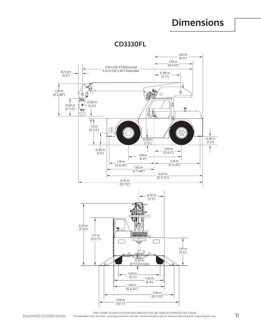
Dimensions
0,30 m(1' 0")
1,33 m(5' 1 1.88")
1,11 m(3' 7.75")
0,99 m(3' 3")
1,29 m(4' 2.88")
0,60 m(1' 1 1.5")
0,08 m(3.12")
1,0 m(3' 3.5")
0,46 m(1' 6")
1,00 m(3' 4.5")
2,03 m(6' 8")
1,74 m(5' 8.38")
1,74 m(5' 8.38")
1,82 m(5' 1 1.88")
3,65 m(11' 11.75")
3,84 m(12' 7")
0,30 m(1' 0")
2,01 m(6' 7.5")
On tires0,25 m (9.5")
1,07 m(3' 6")
0,97 m(3' 2")
2,39 m(7' 10")
1,77 m(5' 9.7")
1,60 m(5' 3") 1,93 m
(6' 4")1,99 m
(6' 6.25")2,81 m
(9' 2.75")3,10 m(10' 2")
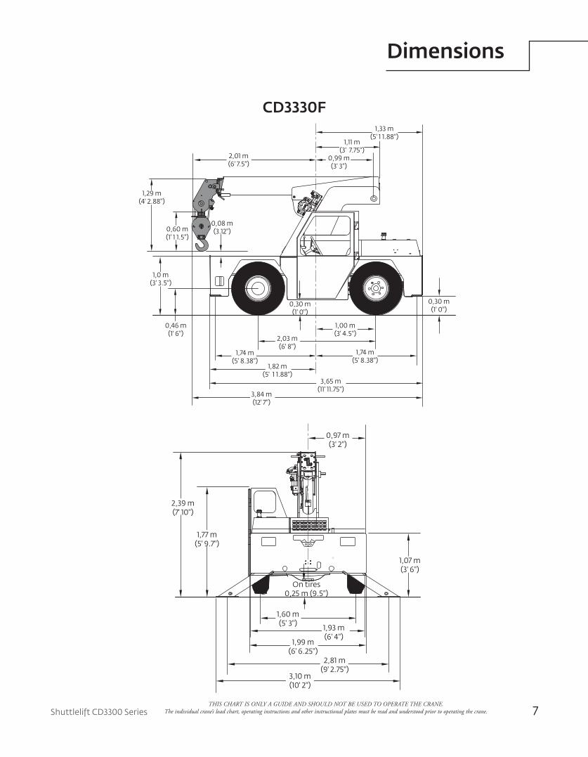
CD3330F
THIS CHART IS ONLY A GUIDE AND SHOULD NOT BE USED TO OPERATE THE CRANE. The individual crane’s load chart, operating instructions and other instructional plates must be read and understood prior to operating the crane.
8
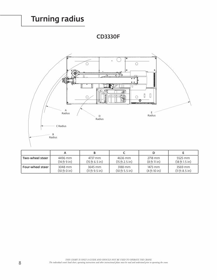
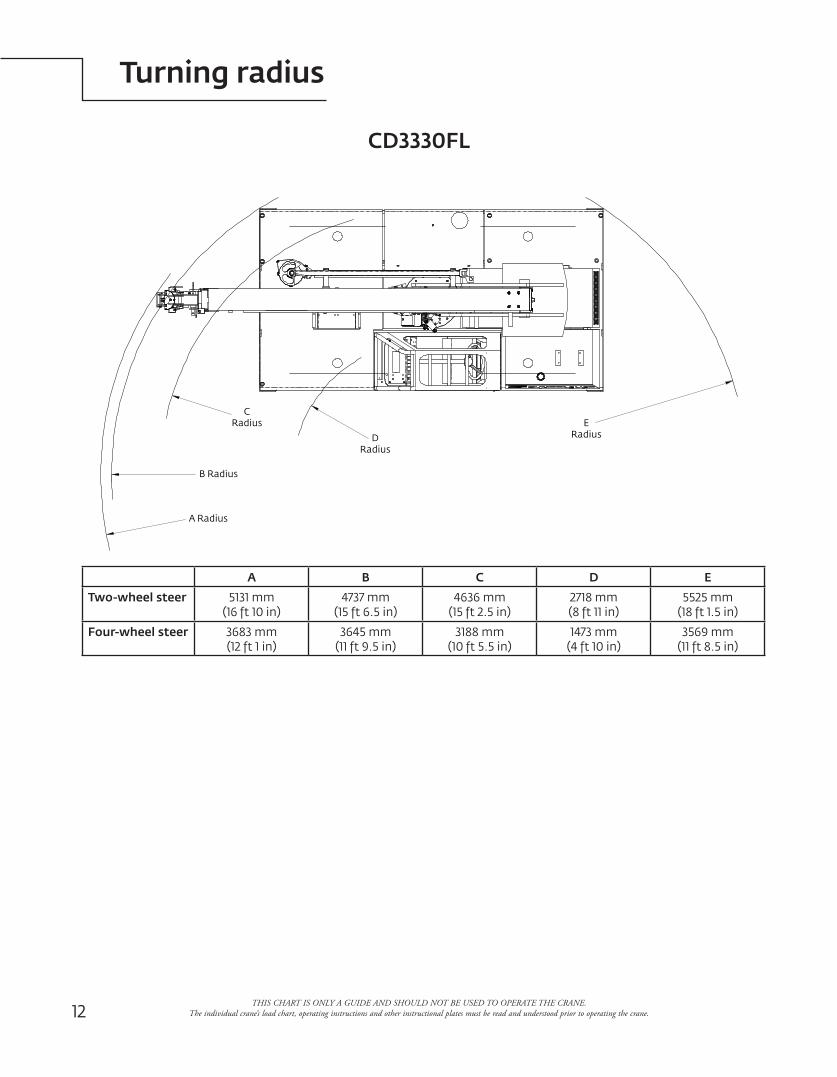
Turning radius
THIS CHART IS ONLY A GUIDE AND SHOULD NOT BE USED TO OPERATE THE CRANE. The individual crane’s load chart, operating instructions and other instructional plates must be read and understood prior to operating the crane.
B Radius
C Radius
A Radius
DRadius
E Radius
CD3330F
A B C D E
Two-wheel steer 4496 mm(14 ft 9 in)
4737 mm(15 ft 6.5 in)
4636 mm(15 ft 2.5 in)
2718 mm(8 ft 11 in)
5525 mm(18 ft 1.5 in)
Four-wheel steer 3048 mm(10 ft 0 in)
3645 mm(11 ft 9.5 in)
3188 mm(10 ft 5.5 in)
1473 mm(4 ft 10 in)
3569 mm(11 ft 8.5 in)
Shuttlelift CD3300 Series 9
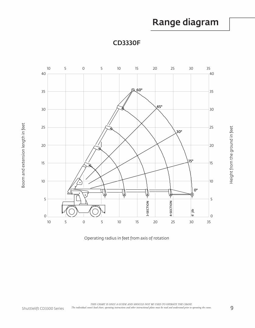
Range diagram
CD3330F
35
5
10
0
5
10
15
20
25
3-SE
CTI
ON
4-SE
CTI
ON
50 1510 2520 30
30
35
40
45°
30°
60°
0°
15°
10 5 0 5 10 15 20 25 30 35
10
0
5
15
20
30
25
35
40
6' j
ib
Boo
m a
nd e
xten
sion
leng
th in
feet
Operating radius in feet from axis of rotation
Hei
ght
from
the
gro
und
in fe
et
THIS CHART IS ONLY A GUIDE AND SHOULD NOT BE USED TO OPERATE THE CRANE. The individual crane’s load chart, operating instructions and other instructional plates must be read and understood prior to operating the crane.
10
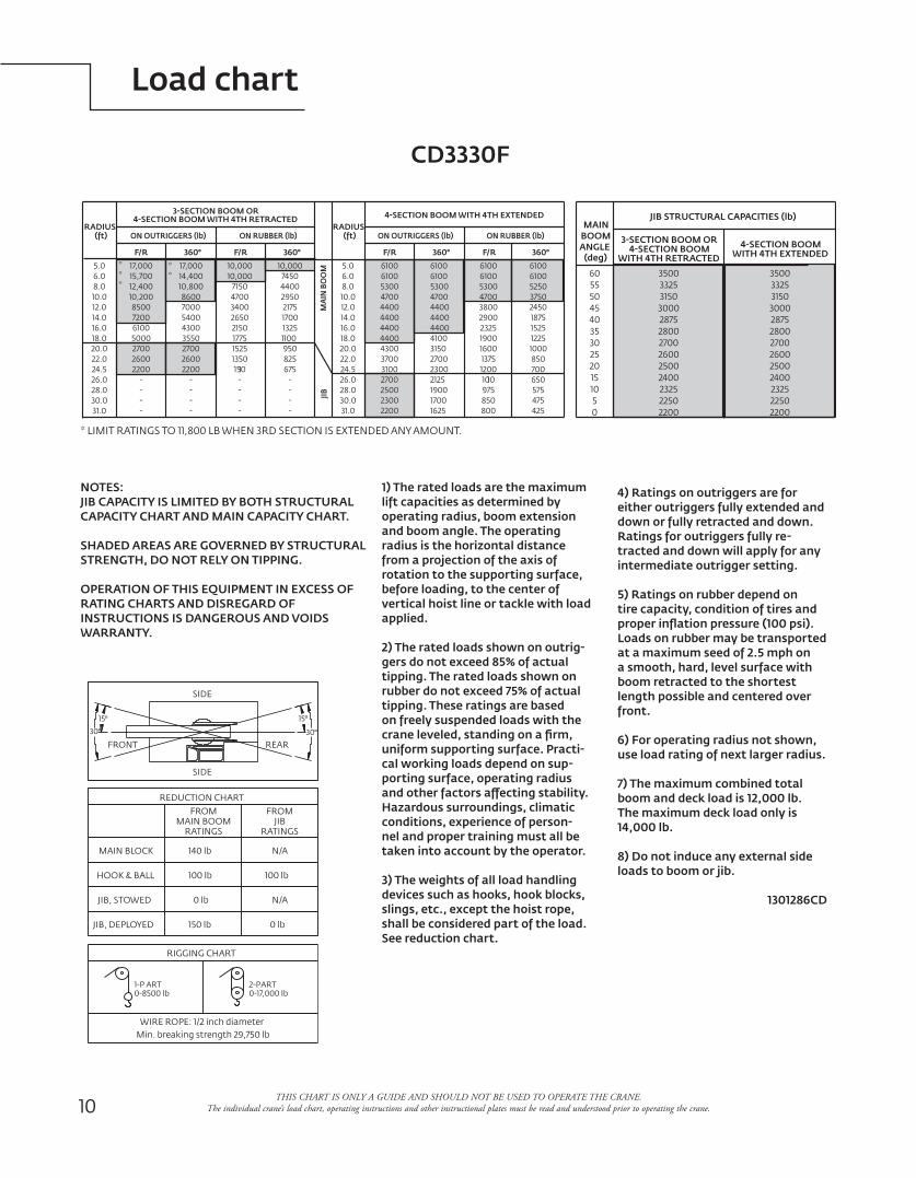
Load chart
THIS CHART IS ONLY A GUIDE AND SHOULD NOT BE USED TO OPERATE THE CRANE. The individual crane’s load chart, operating instructions and other instructional plates must be read and understood prior to operating the crane.
CD3330F
1) The rated loads are the maximum lift capacities as determined by operating radius, boom extension and boom angle. The operating radius is the horizontal distance from a projection of the axis of rotation to the supporting surface, before loading, to the center of vertical hoist line or tackle with load applied.
2) The rated loads shown on outrig-gers do not exceed 85% of actual tipping. The rated loads shown on rubber do not exceed 75% of actual tipping. These ratings are based on freely suspended loads with the crane leveled, standing on a firm, uniform supporting surface. Practi-cal working loads depend on sup-porting surface, operating radius and other factors affecting stability. Hazardous surroundings, climatic conditions, experience of person-nel and proper training must all be taken into account by the operator.
3) The weights of all load handling devices such as hooks, hook blocks, slings, etc., except the hoist rope, shall be considered part of the load. See reduction chart.
NOTES:JIB CAPACITY IS LIMITED BY BOTH STRUCTURAL CAPACITY CHART AND MAIN CAPACITY CHART.
SHADED AREAS ARE GOVERNED BY STRUCTURAL STRENGTH, DO NOT RELY ON TIPPING.
OPERATION OF THIS EQUIPMENT IN EXCESS OF RATING CHARTS AND DISREGARD OF INSTRUCTIONS IS DANGEROUS AND VOIDS WARRANTY.
0-17,000 lb2-PART
0-8500 lb1-P ART
RIGGING CHART
FRONT REAR
SIDE
WIRE ROPE: 1/2 inch diameterMin. breaking strength 29,750 lb
SIDE
REDUCTION CHART
MAIN BOOMFROM
RATINGSJIB
FROM
RATINGS
MAIN BLOCK
HOOK & BALL
JIB, STOWED
JIB, DEPLOYED
140 lb
100 lb
0 lb
150 lb
N/A
100 lb
N/A
0 lb
15°
30°
15°
30°
ON RUBBER (lb)ON OUTRIGGERS (lb)
MA
IN B
OO
MJIB
17,0005.0
RADIUS(ft)
6.0 15,7008.0 12,40010.0 10,20012.0 850014.0 720016.018.020.022.024.526.028.030.031.0
17,00014,40010,80086007000
2600
--
-2200
35502700
43005400
- -
2200
--
500027002600
6100
-
10,00010,000
10,0007450
2175
825
---
675-
1100950
13251700
44002950
3400
1350
-
--
1150-
17751525
21502650
71504700
F/R 360° F/R 360°
3-SECTION BOOM OR4-SECTION BOOM WITH 4TH RETRACTED
ON RUBBER (lb)ON OUTRIGGERS (lb)
61005.0
RADIUS(ft)
6.0 61008.0 530010.0 470012.0 440014.0 440016.018.020.022.024.526.028.030.031.0
61006100530047004400
2700
19001700
21252300
41003150
44004400
2200 1625
3100
25002700
440043003700
4400
2300
61006100
61006100
2450
850
575475425
700650
12251000
15251875
52503750
3800
1375
975
800850
12001100
19001600
23252900
53004700
F/R 360° F/R 360°
4-SECTION BOOM WITH 4TH EXTENDED
***
**
10
4-SECTION BOOM
2875
2400
2200
28002700
3500
31503000
4-SECTION BOOM
3325
26002500
22502325
3-SECTION BOOM OR
WITH 4TH RETRACTED WITH 4TH EXTENDED
2875
2400
2200
28002700
3500
31503000
3325
26002500
22502325
BOOM
(deg)ANGLE
MAIN
60
40
15
0
3035
455055
2520
5
JIB STRUCTURAL CAPACITIES (lb)
* LIMIT RATINGS TO 11,800 LB WHEN 3RD SECTION IS EXTENDED ANY AMOUNT.
4) Ratings on outriggers are for either outriggers fully extended and down or fully retracted and down. Ratings for outriggers fully re-tracted and down will apply for any intermediate outrigger setting.
5) Ratings on rubber depend on tire capacity, condition of tires and proper inflation pressure (100 psi). Loads on rubber may be transported at a maximum seed of 2.5 mph on a smooth, hard, level surface with boom retracted to the shortest length possible and centered over front.
6) For operating radius not shown, use load rating of next larger radius.
7) The maximum combined total boom and deck load is 12,000 lb. The maximum deck load only is 14,000 lb.
8) Do not induce any external side loads to boom or jib.
1301286CD
0-17,000 lb2-PART
0-8500 lb1-P ART
RIGGING CHART
FRONT REAR
SIDE
WIRE ROPE: 1/2 inch diameterMin. breaking strength 29,750 lb
SIDE
REDUCTION CHART
MAIN BOOMFROM
RATINGSJIB
FROM
RATINGS
MAIN BLOCK
HOOK & BALL
JIB, STOWED
JIB, DEPLOYED
140 lb
100 lb
0 lb
150 lb
N/A
100 lb
N/A
0 lb
15°
30°
15°
30°
ON RUBBER (lb)ON OUTRIGGERS (lb)
MA
IN B
OO
MJIB
17,0005.0
RADIUS(ft)
6.0 15,7008.0 12,40010.0 10,20012.0 850014.0 720016.018.020.022.024.526.028.030.031.0
17,00014,40010,80086007000
2600
--
-2200
35502700
43005400
- -
2200
--
500027002600
6100
-
10,00010,000
10,0007450
2175
825
---
675-
1100950
13251700
44002950
3400
1350
-
--
1150-
17751525
21502650
71504700
F/R 360° F/R 360°
3-SECTION BOOM OR4-SECTION BOOM WITH 4TH RETRACTED
ON RUBBER (lb)ON OUTRIGGERS (lb)
61005.0
RADIUS(ft)
6.0 61008.0 530010.0 470012.0 440014.0 440016.018.020.022.024.526.028.030.031.0
61006100530047004400
2700
19001700
21252300
41003150
44004400
2200 1625
3100
25002700
440043003700
4400
2300
61006100
61006100
2450
850
575475425
700650
12251000
15251875
52503750
3800
1375
975
800850
12001100
19001600
23252900
53004700
F/R 360° F/R 360°
4-SECTION BOOM WITH 4TH EXTENDED
***
**
10
4-SECTION BOOM
2875
2400
2200
28002700
3500
31503000
4-SECTION BOOM
3325
26002500
22502325
3-SECTION BOOM OR
WITH 4TH RETRACTED WITH 4TH EXTENDED
2875
2400
2200
28002700
3500
31503000
3325
26002500
22502325
BOOM
(deg)ANGLE
MAIN
60
40
15
0
3035
455055
2520
5
JIB STRUCTURAL CAPACITIES (lb)
* LIMIT RATINGS TO 11,800 LB WHEN 3RD SECTION IS EXTENDED ANY AMOUNT.
Shuttlelift CD3300 Series 11
Dimensions
THIS CHART IS ONLY A GUIDE AND SHOULD NOT BE USED TO OPERATE THE CRANE. The individual crane’s load chart, operating instructions and other instructional plates must be read and understood prior to operating the crane.
CD3330FL1,83 m(6' 0")
3,76 m (12' 4") Retracted9,21 m (30' 2.50") Extended
1,45 m(4' 9.13")
0,99 m(3' 3")
16,5 cm(6.5")
1,29 m(4' 2.88")
0,08 m(3.12")
1,0 m(3' 3.5")
0,30 m(1' 0")
0,30 m(1' 0")
0,46 m(1' 6")
1,74 m(5' 8.38")
2,03 m(6' 8")
1,82 m(5' 11.88")
1,00 m(3' 4.5")
1,74 m(5' 8.38")
3,65 m(11' 11.75")
4,76 m(15' 7.5")
0,60 m(1' 11.5")
0,25 m(9' 5") On tires
0,97 m(3' 2")
2,39 m(7' 10")
1,77 m(5' 9.7")
1,60 m(5' 3") 1,93 m
(6' 4")1,99 m
(6' 6.25")2,81 m
(9' 2.75")3,10 m(10' 2")
1,07 m(3' 6")
12
Turning radius
THIS CHART IS ONLY A GUIDE AND SHOULD NOT BE USED TO OPERATE THE CRANE. The individual crane’s load chart, operating instructions and other instructional plates must be read and understood prior to operating the crane.
A B C D E
Two-wheel steer 5131 mm(16 ft 10 in)
4737 mm(15 ft 6.5 in)
4636 mm(15 ft 2.5 in)
2718 mm(8 ft 11 in)
5525 mm(18 ft 1.5 in)
Four-wheel steer 3683 mm(12 ft 1 in)
3645 mm(11 ft 9.5 in)
3188 mm(10 ft 5.5 in)
1473 mm(4 ft 10 in)
3569 mm(11 ft 8.5 in)
C Radius
A Radius
B Radius
E RadiusD
Radius
CD3330FL
Shuttlelift CD3300 Series 13
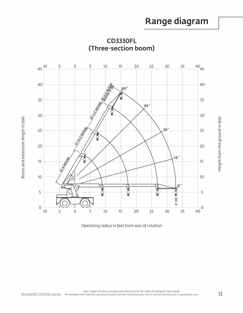
Range diagram
THIS CHART IS ONLY A GUIDE AND SHOULD NOT BE USED TO OPERATE THE CRANE. The individual crane’s load chart, operating instructions and other instructional plates must be read and understood prior to operating the crane.
CD3330FL (Three-section boom)
5
10
15
20
25
30
35
40
45
10 5 0 5 10 15 20 25 30 35 40
10 5 0 5 10 15 20 25 30 35 40
60˚
45˚
15˚
0˚
6' J
IB
30˚
0
5
10
15
20
25
30
35
40
45
0
12'-4
" BO
OM
17'-1
0.5"
BO
OM
30'-2
.5" B
OO
M36
'-2.5
" BO
OM
WIT
H 6'
-0" J
IB
Boo
m a
nd e
xten
sion
leng
th in
feet
Operating radius in feet from axis of rotationH
eigh
t fr
om t
he g
roun
d in
feet
14
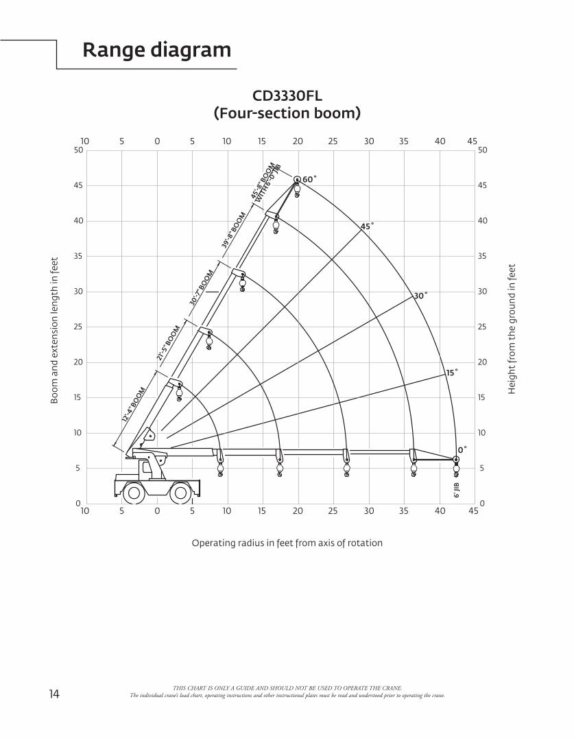
Range diagram
THIS CHART IS ONLY A GUIDE AND SHOULD NOT BE USED TO OPERATE THE CRANE. The individual crane’s load chart, operating instructions and other instructional plates must be read and understood prior to operating the crane.
CD3330FL (Four-section boom)
6' JI
B0˚
15˚
30˚
45˚
60˚
50
45
40
35
30
25
20
15
10
5
0
50
45
40
35
30
25
20
15
10
5
010 5 0 5 10 15 20 25 30 35 40 45
10 5 0 5 10 15 20 25 30 35 40 45
12'-4
" BO
OM
21'-5
" BO
OM
30'-7
" BO
OM
39'-8
" BO
OM
45'-8
" BO
OM
WIT
H 6'
-0" J
IB
Boo
m a
nd e
xten
sion
leng
th in
feet
Operating radius in feet from axis of rotation
Hei
ght
from
the
gro
und
in fe
et
Shuttlelift CD3300 Series 15
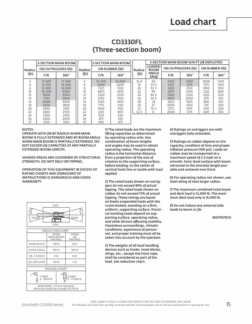
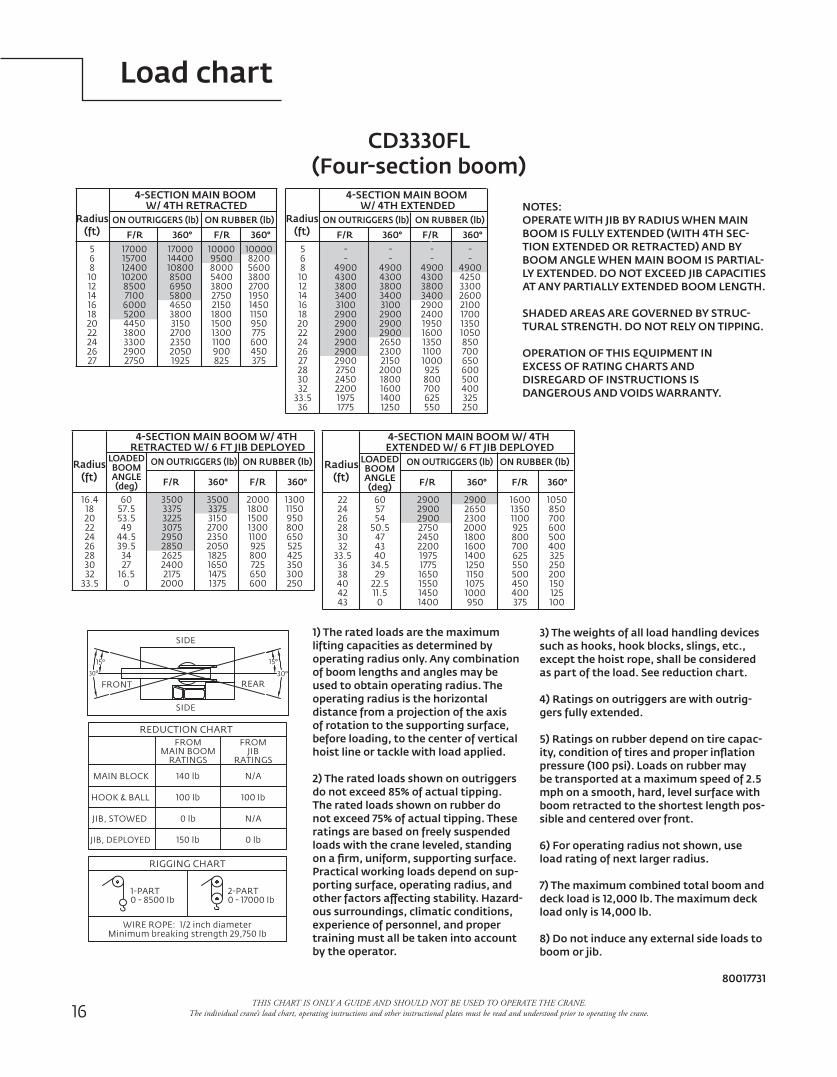
Load chart
THIS CHART IS ONLY A GUIDE AND SHOULD NOT BE USED TO OPERATE THE CRANE. The individual crane’s load chart, operating instructions and other instructional plates must be read and understood prior to operating the crane.
CD3330FL (Three-section boom)
1) The rated loads are the maximum lifting capacities as determined by operating radius only. Any combination of boom lengths and angles may be used to obtain operating radius. The operating radius is the horizontal distance from a projection of the axis of rotation to the supporting surface, before loading, to the center of vertical hoist line or tackle with load applied.
2) The rated loads shown on outrig-gers do not exceed 85% of actual tipping. The rated loads shown on rubber do not exceed 75% of actual tipping. These ratings are based on freely suspended loads with the crane leveled, standing on a firm, uniform, supporting surface. Practi-cal working loads depend on sup-porting surface, operating radius, and other factors affecting stability. Hazardous surroundings, climatic conditions, experience of person-nel, and proper training must all be taken into account by the operator.
3) The weights of all load handling devices such as hooks, hook blocks, slings, etc., except the hoist rope, shall be considered as part of the load. See reduction chart.
NOTES:OPERATE WITH JIB BY RADIUS WHEN MAIN BOOM IS FULLY EXTENDED AND BY BOOM ANGLE WHEN MAIN BOOM IS PARTIALLY EXTENDED. DO NOT EXCEED JIB CAPACITIES AT ANY PARTIALLY EXTENDED BOOM LENGTH.
SHADED AREAS ARE GOVERNED BY STRUCTURAL STRENGTH. DO NOT RELY ON TIPPING.
OPERATION OF THIS EQUIPMENT IN EXCESS OF RATING CHARTS AND DISREGARD OF INSTRUCTIONS IS DANGEROUS AND VOIDS WARRANTY.
SIDE
SIDE
REARFRONT
15˚
30˚
15˚
30˚
REDUCTION CHART
MAIN BLOCK
HOOK & BALL
JIB, STOWED
JIB, DEPLOYED
FROMMAIN BOOM
RATINGS
FROMJIB
RATINGS
140 lb N/A
100 lb 100 lb
0 lb N/A
150 lb 0 lb
RIGGING CHART
1-PART0 - 8500 lb
2-PART0 - 17,000 lb
WIRE ROPE: 1/2 inch diameterMinimum breaking strength 29,750 lb
Radius(ft)
3-SECTION MAIN BOOM
ON OUTRIGGERS (lb)
F/R 360˚
56810121416182022242627
17,00015,70012,40010,20085007100
6000520044503800330029002750
17,00014,40010,8008500695058004650380031502700235020501925
Radius(ft)
3-SECTION MAIN BOOM
ON RUBBER (lb)
F/R 360˚
56810121416182022242627
10,0009500732548753550275021501775145012251025875850
10,0008200512534752550192514501150950800650525475
Radius(ft)
3-SECTION MAIN BOOM W/6 FT JIB DEPLOYED
ON OUTRIGGERS (lb)
F/R 360˚
16.41820222426283032
33.5
6057.553.5
4944.539.5
34 2716.5
0
350033753225307529502850262524002175
2000
3500337531502700235020501825165014751375
ON RUBBER (lb)
F/R 360˚
20001775145012251025875800725650600
13001150950800650525425350300250
LOADEDBOOMANGLE(deg)
YB4409XL 3-section boom
4) Ratings on outriggers are withoutriggers fully extended.
5) Ratings on rubber depend on tire capacity, condition of tires and proper inflation pressure (100 psi). Loads on rubber may be transported at a maximum speed of 2.5 mph on a smooth, hard, level surface with boom retracted to the shortest length pos-sible and centered over front.
6) For operating radius not shown, use load rating of next larger radius.
7) The maximum combined total boom and deck load is 12,000 lb. The maxi-mum deck load only is 14,000 lb.
8) Do not induce any external side loads to boom or jib.
80017679CD
SIDE
SIDE
REARFRONT
15˚
30˚
15˚
30˚
REDUCTION CHART
MAIN BLOCK
HOOK & BALL
JIB, STOWED
JIB, DEPLOYED
FROMMAIN BOOM
RATINGS
FROMJIB
RATINGS
140 lb N/A
100 lb 100 lb
0 lb N/A
150 lb 0 lb
RIGGING CHART
1-PART0 - 8500 lb
2-PART0 - 17,000 lb
WIRE ROPE: 1/2 inch diameterMinimum breaking strength 29,750 lb
Radius(ft)
3-SECTION MAIN BOOM
ON OUTRIGGERS (lb)
F/R 360˚
56810121416182022242627
17,00015,70012,40010,20085007100
6000520044503800330029002750
17,00014,40010,8008500695058004650380031502700235020501925
Radius(ft)
3-SECTION MAIN BOOM
ON RUBBER (lb)
F/R 360˚
56810121416182022242627
10,0009500732548753550275021501775145012251025875850
10,0008200512534752550192514501150950800650525475
Radius(ft)
3-SECTION MAIN BOOM W/6 FT JIB DEPLOYED
ON OUTRIGGERS (lb)
F/R 360˚
16.41820222426283032
33.5
6057.553.5
4944.539.5
34 2716.5
0
350033753225307529502850262524002175
2000
3500337531502700235020501825165014751375
ON RUBBER (lb)
F/R 360˚
20001775145012251025875800725650600
13001150950800650525425350300250
LOADEDBOOMANGLE(deg)
YB4409XL 3-section boom
16
Load chart
THIS CHART IS ONLY A GUIDE AND SHOULD NOT BE USED TO OPERATE THE CRANE. The individual crane’s load chart, operating instructions and other instructional plates must be read and understood prior to operating the crane.
SIDE
SIDE
REARFRONT
15°30°
15°
30°
REDUCTION CHART
MAIN BLOCK
HOOK & BALL
JIB, STOWED
JIB, DEPLOYED
FROMMAIN BOOM
RATINGS
FROMJIB
RATINGS
140 lb N/A
100 lb 100 lb
0 lb N/A
150 lb 0 lb
RIGGING CHART
1-PART0 - 8500 lb
2-PART0 - 17000 lb
WIRE ROPE: 1/2 inch diameterMinimum breaking strength 29,750 lb
Radius(ft)
4-SECTION MAIN BOOM W/ 4TH RETRACTED
ON OUTRIGGERS (lb)
F/R 360°56810121416182022242627
1700015700124001020085007100
6000520044503800330029002750
1700014400108008500695058004650380031502700235020501925
ON RUBBER (lb)
F/R 360°100009500800054003800275021501800150013001100900825
100008200560038002700195014501150950775600450375
Radius(ft)
4-SECTION MAIN BOOM W/ 4TH EXTENDED
ON OUTRIGGERS (lb)
F/R 360°56810121416182022242627283032
33.536
--
4900430038003400310029002900290029002900290027502450220019751775
--
4900430038003400310029002900290026502300215020001800160014001250
ON RUBBER (lb)
F/R 360°--
49004300380034002900240019501600135011001000925800700625550
--
49004250330026002100170013501050850700650600500400325250
Radius(ft)
4-SECTION MAIN BOOM W/ 4TH RETRACTED W/ 6 FT JIB DEPLOYED
ON OUTRIGGERS (lb)
F/R 360°
16.41820222426283032
33.5
6057.553.549
44.539.5
3427
16.50
350033753225307529502850262524002175
2000
3500337531502700235020501825165014751375
ON RUBBER (lb)
F/R 360°
20001800150013001100925800725650600
13001150950800650525425350300250
LOADEDBOOMANGLE(deg)
Radius(ft)
4-SECTION MAIN BOOM W/ 4TH EXTENDED W/ 6 FT JIB DEPLOYED
ON OUTRIGGERS (lb)
F/R 360°
222426283032
33.53638404243
605754
50.5474340
34.529
22.511.5
0
290029002900275024502200197517751650155014501400
29002650230020001800160014001250115010751000950
ON RUBBER (lb)
F/R 360°
160013501100925800700625550500450400375
1050850700600500400325250200150125100
LOADEDBOOMANGLE(deg)
CD3330FL (Four-section boom)
1) The rated loads are the maximum lifting capacities as determined by operating radius only. Any combination of boom lengths and angles may be used to obtain operating radius. The operating radius is the horizontal distance from a projection of the axis of rotation to the supporting surface, before loading, to the center of vertical hoist line or tackle with load applied.
2) The rated loads shown on outriggers do not exceed 85% of actual tipping. The rated loads shown on rubber do not exceed 75% of actual tipping. These ratings are based on freely suspended loads with the crane leveled, standing on a firm, uniform, supporting surface. Practical working loads depend on sup-porting surface, operating radius, and other factors affecting stability. Hazard-ous surroundings, climatic conditions, experience of personnel, and proper training must all be taken into account by the operator.
NOTES:OPERATE WITH JIB BY RADIUS WHEN MAIN BOOM IS FULLY EXTENDED (WITH 4TH SEC-TION EXTENDED OR RETRACTED) AND BY BOOM ANGLE WHEN MAIN BOOM IS PARTIAL-LY EXTENDED. DO NOT EXCEED JIB CAPACITIES AT ANY PARTIALLY EXTENDED BOOM LENGTH.
SHADED AREAS ARE GOVERNED BY STRUC-TURAL STRENGTH. DO NOT RELY ON TIPPING.
OPERATION OF THIS EQUIPMENT IN EXCESS OF RATING CHARTS AND DISREGARD OF INSTRUCTIONS ISDANGEROUS AND VOIDS WARRANTY.
3) The weights of all load handling devices such as hooks, hook blocks, slings, etc., except the hoist rope, shall be considered as part of the load. See reduction chart.
4) Ratings on outriggers are with outrig-gers fully extended.
5) Ratings on rubber depend on tire capac-ity, condition of tires and proper inflation pressure (100 psi). Loads on rubber may be transported at a maximum speed of 2.5 mph on a smooth, hard, level surface with boom retracted to the shortest length pos-sible and centered over front.
6) For operating radius not shown, use load rating of next larger radius.
7) The maximum combined total boom and deck load is 12,000 lb. The maximum deck load only is 14,000 lb.
8) Do not induce any external side loads to boom or jib.
80017731
SIDE
SIDE
REARFRONT
15°30°
15°
30°
REDUCTION CHART
MAIN BLOCK
HOOK & BALL
JIB, STOWED
JIB, DEPLOYED
FROMMAIN BOOM
RATINGS
FROMJIB
RATINGS
140 lb N/A
100 lb 100 lb
0 lb N/A
150 lb 0 lb
RIGGING CHART
1-PART0 - 8500 lb
2-PART0 - 17000 lb
WIRE ROPE: 1/2 inch diameterMinimum breaking strength 29,750 lb
Radius(ft)
4-SECTION MAIN BOOM W/ 4TH RETRACTED
ON OUTRIGGERS (lb)
F/R 360°56810121416182022242627
1700015700124001020085007100
6000520044503800330029002750
1700014400108008500695058004650380031502700235020501925
ON RUBBER (lb)
F/R 360°100009500800054003800275021501800150013001100900825
100008200560038002700195014501150950775600450375
Radius(ft)
4-SECTION MAIN BOOM W/ 4TH EXTENDED
ON OUTRIGGERS (lb)
F/R 360°56810121416182022242627283032
33.536
--
4900430038003400310029002900290029002900290027502450220019751775
--
4900430038003400310029002900290026502300215020001800160014001250
ON RUBBER (lb)
F/R 360°--
49004300380034002900240019501600135011001000925800700625550
--
49004250330026002100170013501050850700650600500400325250
Radius(ft)
4-SECTION MAIN BOOM W/ 4TH RETRACTED W/ 6 FT JIB DEPLOYED
ON OUTRIGGERS (lb)
F/R 360°
16.41820222426283032
33.5
6057.553.549
44.539.5
3427
16.50
350033753225307529502850262524002175
2000
3500337531502700235020501825165014751375
ON RUBBER (lb)
F/R 360°
20001800150013001100925800725650600
13001150950800650525425350300250
LOADEDBOOMANGLE(deg)
Radius(ft)
4-SECTION MAIN BOOM W/ 4TH EXTENDED W/ 6 FT JIB DEPLOYED
ON OUTRIGGERS (lb)
F/R 360°
222426283032
33.53638404243
605754
50.5474340
34.529
22.511.5
0
290029002900275024502200197517751650155014501400
29002650230020001800160014001250115010751000950
ON RUBBER (lb)
F/R 360°
160013501100925800700625550500450400375
1050850700600500400325250200150125100
LOADEDBOOMANGLE(deg)
Shuttlelift CD3300 Series 17
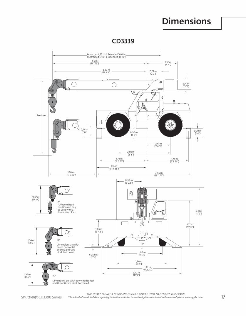
Dimensions
THIS CHART IS ONLY A GUIDE AND SHOULD NOT BE USED TO OPERATE THE CRANE. The individual crane’s load chart, operating instructions and other instructional plates must be read and understood prior to operating the crane.
Retracted 4,22 m & Extended 10,01 m(Retracted 13’ 10” & Extended 32’ 10”)
394 m(15.5”)
0,51 m(2’ 2”)
0,30 m(1’ 0”)0,30 m
(1’ 0”)
0,46 m(1’ 6”)
10”
6,35 cm(2.5”)
30°
*1,37 m(54.0”)
1,34 m(53.0”)
1, 10 m(43.5”)
0°*0° boom headposition can onlybe used with a down haul block
80°
Dimensions are with boom horizontaland the anti-two block bottomed.
See Insert
Dimensions are with boom horizontaland the anti-two block bottomed.
3,5 m(11’ 7.75”)
3,39 m(11’ 5.5”)
1.74 m(5’ 8.38”)
2,03 m(6' 8")
1,00 m(3’ 4.5”)
1,74 m(5’ 8.38”)
1,74 m(5’ 11.88”)
3,65 m(11’ 11.75”)
1,70 m(5’ 6.92”)
0,98 m(3’ 2.5”)
2,21 m(7’ 3”)
1,77 m(5’ 9.7”)
1,03 m(3’ 4.5”)
1,60 m(5’ 3”)
1,96 m(6’ 5”)
1,81 m(9’ 2.75”)
3,10 m(10’ 2”)
1,32 m(4’ 4”)
CD3339
18
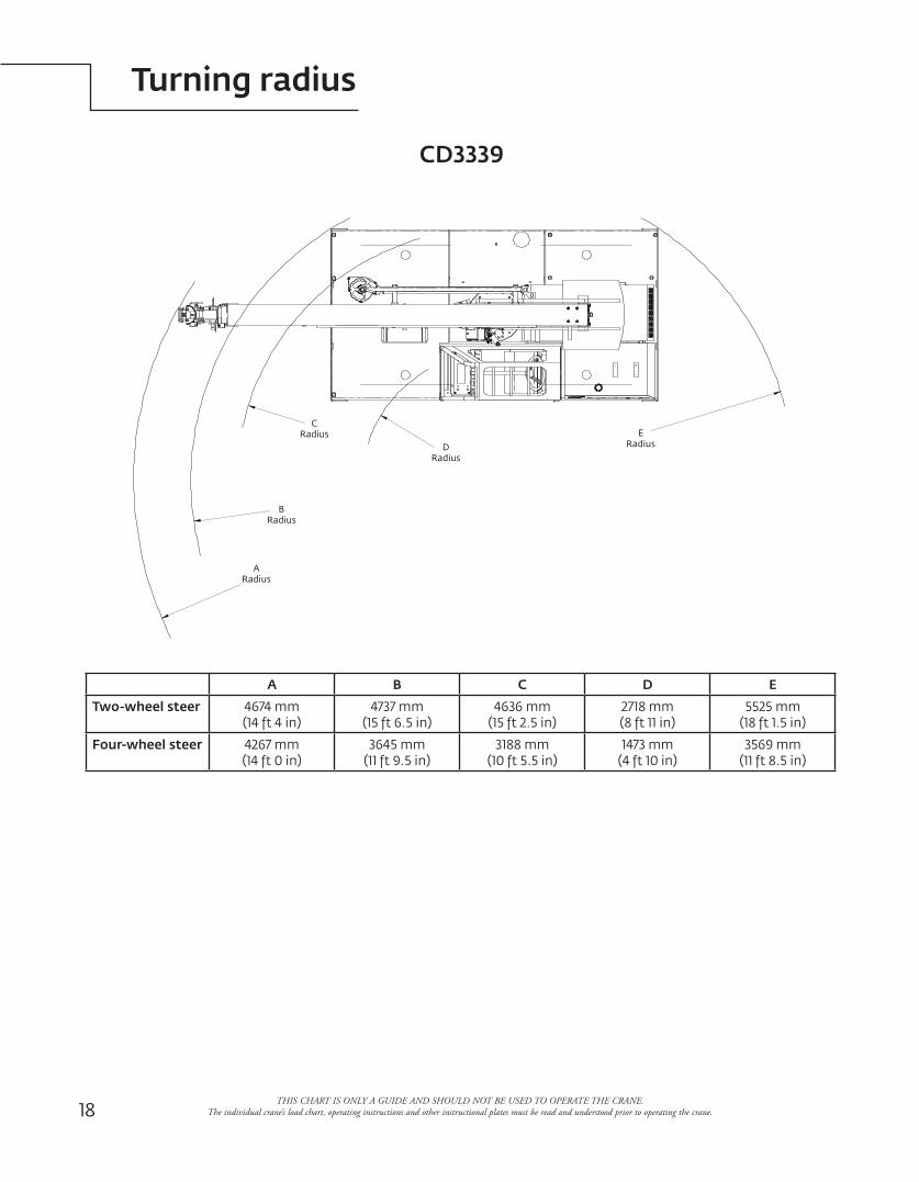
Turning radius
THIS CHART IS ONLY A GUIDE AND SHOULD NOT BE USED TO OPERATE THE CRANE. The individual crane’s load chart, operating instructions and other instructional plates must be read and understood prior to operating the crane.
A B C D E
Two-wheel steer 4674 mm(14 ft 4 in)
4737 mm(15 ft 6.5 in)
4636 mm(15 ft 2.5 in)
2718 mm(8 ft 11 in)
5525 mm(18 ft 1.5 in)
Four-wheel steer 4267 mm(14 ft 0 in)
3645 mm(11 ft 9.5 in)
3188 mm(10 ft 5.5 in)
1473 mm(4 ft 10 in)
3569 mm(11 ft 8.5 in)
B Radius
C Radius
A Radius
DRadius
E Radius
CD3339
Shuttlelift CD3300 Series 19
Range diagram
THIS CHART IS ONLY A GUIDE AND SHOULD NOT BE USED TO OPERATE THE CRANE. The individual crane’s load chart, operating instructions and other instructional plates must be read and understood prior to operating the crane.
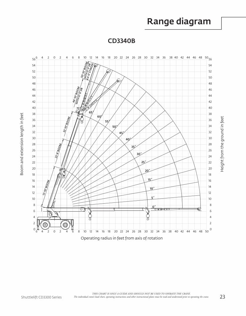
CD3339
56
54
52
50
48
46
44
42
40
38
36
34
32
30
28
26
24
22
20
18
16
14
12
10
8
6
4
2
0
56
54
52
50
48
46
44
42
40
38
36
34
32
30
28
26
24
22
20
18
16
14
12
10
8
6
4
2
0 6 4 2 0 2 4 6 8 10 12 14 16 18 20 22 24 26 28 30 32 34 36 38 40 42 44 46 48
6 4 2 0 2 4 6 8 10 12 14 16 18 20 22 24 26 28 30 32 34 36 38 40 42 44 46 48
12' Jib 18' Jib
boom 4,22 m (13' 10")
boom 7,11 m (23' 4")
boom 10,10 m (32' 10")
with 3,66 m (12')13,67 m (44' 10") boom
osettable boom extension
with 3,66 m (12') to 5,49 m (18') 15,50 m (50' 10") boom
telescopic osettable boom extension
5°
10°
15°
20°
25°
30°
35°
40°
45°
50°
55°
60°
65°
70°72°
Boo
m a
nd e
xten
sion
leng
th in
feet
Operating radius in feet from axis of rotation
Hei
ght
from
the
gro
und
in fe
et
THIS CHART IS ONLY A GUIDE AND SHOULD NOT BE USED TO OPERATE THE CRANE. The individual crane’s load chart, operating instructions and other instructional plates must be read and understood prior to operating the crane.20
Load chart
F/R
ON OUTRIGGERS (lb) ON RUBBER(lb)
360° F/R 360°RADIUS (ft)
BOOM RETRACTED
BOOM EXTENDED
ANY BOOM
BOOM RETRACTED
BOOM EXTENDED
ANY BOOM
MA
IN B
OO
MJI
B
5.06.08.010.012.014.016.018.020.022.024.026.028.031.034.036.038.040.042.044.046.048.0
18,00015,70012,20010,2008400
14,70014,40012,20010,200840072006200540048304000348030202680227019601770159014201270120011601110
18,00015,00011,40091007600
14,70014,40011,400910076006500531043403610303025902250201017401500135012001050930880820760
11,50010,000
810054803920304024201970164013701160990830650510430350280210190170140
940075005040353025901970156012501020850710590490360250180130806040200
JIB STRUCTURAL CAPACITIES (lb)
18 ft JIB12 ft JIB
0°OFFSET
15°OFFSET
30°OFFSET
MAINBOOMANGLE (deg)
0°OFFSET
15°OFFSET
30°OFFSET
727065605550454035302520151050
7500700057004500350028002300200017751600145013501300127512251200
5100480041003500300025002200190016751500140013501300
3500340031002800255023002000180016001400
4000375032002800245021501900170015251400127511751100105010251000
3300310027002400215019501750160014501300120011251100
2300220020001850170016001500140013501300
SIDE
REAR
SIDE
FRONT
30°
15°
30°
15°
REDUCTION CHART
MAIN BLOCK
HOOK & BALL
JIB, STOWED
JIB, DEPLOYED
FROM MAIN BOOM
RATINGS
FROM MAIN JIBRATINGS
140 lb
100 lb
0 lb
450 lb 0 lb
100 lb
N/A
N/A
RIGGING CHART
1-PART0 - 10,000 lb
2-PART0 - 18,000 lb
WIRE ROPE: 9/16 in diameterMin. breaking strength 35,000 lb
CD3339
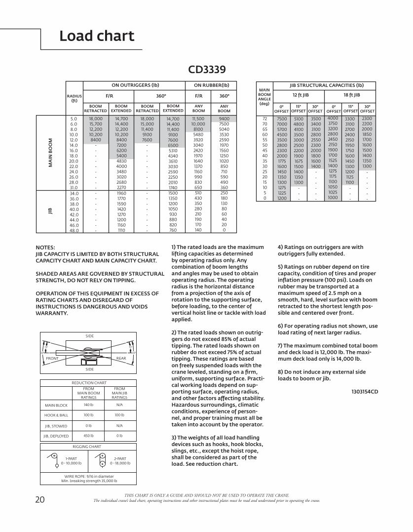
1) The rated loads are the maximum lifting capacities as determined by operating radius only. Any combination of boom lengths and angles may be used to obtain operating radius. The operating radius is the horizontal distance from a projection of the axis of rotation to the supporting surface, before loading, to the center of vertical hoist line or tackle with load applied.
2) The rated loads shown on outrig-gers do not exceed 85% of actual tipping. The rated loads shown on rubber do not exceed 75% of actual tipping. These ratings are based on freely suspended loads with the crane leveled, standing on a firm, uniform, supporting surface. Practi-cal working loads depend on sup-porting surface, operating radius, and other factors affecting stability. Hazardous surroundings, climatic conditions, experience of person-nel, and proper training must all be taken into account by the operator.
3) The weights of all load handling devices such as hooks, hook blocks, slings, etc., except the hoist rope, shall be considered as part of the load. See reduction chart.
4) Ratings on outriggers are withoutriggers fully extended.
5) Ratings on rubber depend on tire capacity, condition of tires and proper inflation pressure (100 psi). Loads on rubber may be transported at a maximum speed of 2.5 mph on a smooth, hard, level surface with boom retracted to the shortest length pos-sible and centered over front.
6) For operating radius not shown, use load rating of next larger radius.
7) The maximum combined total boom and deck load is 12,000 lb. The maxi-mum deck load only is 14,000 lb.
8) Do not induce any external side loads to boom or jib.
1303154CD
NOTES:JIB CAPACITY IS LIMITED BY BOTH STRUCTURAL CAPACITY CHART AND MAIN CAPACITY CHART.
SHADED AREAS ARE GOVERNED BY STRUCTURAL STRENGTH, DO NOT RELY ON TIPPING.
OPERATION OF THIS EQUIPMENT IN EXCESS OF RATING CHARTS AND DISREGARD OF INSTRUCTIONS IS DANGEROUS AND VOIDS WARRANTY.
F/R
ON OUTRIGGERS (lb) ON RUBBER(lb)
360° F/R 360°RADIUS (ft)
BOOM RETRACTED
BOOM EXTENDED
ANY BOOM
BOOM RETRACTED
BOOM EXTENDED
ANY BOOM
MA
IN B
OO
MJI
B
5.06.08.010.012.014.016.018.020.022.024.026.028.031.034.036.038.040.042.044.046.048.0
18,00015,70012,20010,2008400
14,70014,40012,20010,200840072006200540048304000348030202680227019601770159014201270120011601110
18,00015,00011,40091007600
14,70014,40011,400910076006500531043403610303025902250201017401500135012001050930880820760
11,50010,000
810054803920304024201970164013701160990830650510430350280210190170140
940075005040353025901970156012501020850710590490360250180130806040200
JIB STRUCTURAL CAPACITIES (lb)
18 ft JIB12 ft JIB
0°OFFSET
15°OFFSET
30°OFFSET
MAINBOOMANGLE (deg)
0°OFFSET
15°OFFSET
30°OFFSET
727065605550454035302520151050
7500700057004500350028002300200017751600145013501300127512251200
5100480041003500300025002200190016751500140013501300
3500340031002800255023002000180016001400
4000375032002800245021501900170015251400127511751100105010251000
3300310027002400215019501750160014501300120011251100
2300220020001850170016001500140013501300
SIDE
REAR
SIDE
FRONT
30°
15°
30°
15°
REDUCTION CHART
MAIN BLOCK
HOOK & BALL
JIB, STOWED
JIB, DEPLOYED
FROM MAIN BOOM
RATINGS
FROM MAIN JIBRATINGS
140 lb
100 lb
0 lb
450 lb 0 lb
100 lb
N/A
N/A
RIGGING CHART
1-PART0 - 10,000 lb
2-PART0 - 18,000 lb
WIRE ROPE: 9/16 in diameterMin. breaking strength 35,000 lb

Shuttlelift CD3300 Series 21
Dimensions
THIS CHART IS ONLY A GUIDE AND SHOULD NOT BE USED TO OPERATE THE CRANE. The individual crane’s load chart, operating instructions and other instructional plates must be read and understood prior to operating the crane.
CD3340B
3,55 m(11' - 7.75") 3,49 m
(11' - 5.5")
30o
80o
0o
*0o boomhead position can onlybe used with headache ball.
Dimensions are with the boom horizontaland the anti-two block bottomed.
Retracted 4,22 m (13'-10") and Extended 10,01 m (32' - 10")
See Inset
1,32 m(4' - 4.0")660 mm
(26")
394 mm(15.5")
Main block two-part line
Hook and ballone-part line
394 mm(15.5")
254 mm(10")
305 mm(12")
940 mm(37")
1,64 m(5' - 4.5")
2,01 m(6' - 7.0")1,77 m
(5' - 9.5")1,89 m
(6' - 2.5") 3,66 m(12' - 0")
1,14 m(3' - 9.0")
1,63 m(5' - 4.1")1,83 m
(6' - 0")
2,21 m(7' - 3.0")
2,18 m(7' - 2.0")
1,78 m(5' - 10.0")
1,00 m(3' - 3.5")
1,60 m (5' - 3.0")Track Width
1,93 m (6' - 4.0") Frame Width
2,01 m (6' - 7.0") Max. Machine Width
2,06 m (6' - 9.0") C.L.O.R. Ret. and Down
3,40 m (11' - 2.0") C.L.O.R. Ext. and Down
1105 mm(43.5")
1346 mm(53")
*1372 mm(54")
22
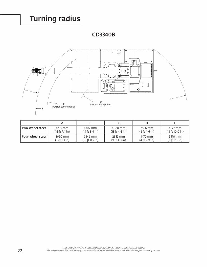
Turning radius
A B C D E
Two-wheel steer 4759 mm(15 ft 7.4 in)
4482 mm(14 ft 8.4 in)
4080 mm(13 ft 4.6 in)
2556 mm(8 ft 4.6 in)
4522 mm(14 ft 10.0 in)
Four-wheel steer 3990 mm(13 ft 1.1 in)
3346 mm(10 ft 11.7 in)
2853 mm(9 ft 4.3 in)
1470 mm(4 ft 9.9 in)
3416 mm(11 ft 2.5 in)
CD3340B
C Outside turning radius
D Inside turning radius
E
B
A
THIS CHART IS ONLY A GUIDE AND SHOULD NOT BE USED TO OPERATE THE CRANE. The individual crane’s load chart, operating instructions and other instructional plates must be read and understood prior to operating the crane.
Shuttlelift CD3300 Series 23
Range diagram
40
400
4
2
6
6 4 2
20
8
10
12
14
16
18
22
24
26
30
28
32
201020 4 6 8 12 14 16 18 3022 24 26 28 32 34 36 38
15˚
20˚
0˚
5˚
10˚
25˚
30˚
35˚
40˚
45˚
46
36
34
38
40
42
44
48
50
52
54
566 4 2
70˚65˚
60˚
55˚
50˚
201020 4 6 8 12 14 16 18 3022 24 26 28 32 34 36 38
42 44 4846
4
2
6
20
8
10
12
14
16
18
22
24
26
30
28
32
46
36
34
38
40
42
44
48
50
52
54
5642 44 4846
72˚
13'-1
0" B
OO
M
23'-4
" BO
OM
32'-1
0" B
OO
M
44'-1
0" B
OO
M50
'-10"
BO
OM
WIT
H 12
'-0" J
IBW
ITH
12'-0
" JIB
& 6'
-0" S
TIN
GER
50
500
CD3340B
Boo
m a
nd e
xten
sion
leng
th in
feet
Operating radius in feet from axis of rotation
Hei
ght
from
the
gro
und
in fe
et
THIS CHART IS ONLY A GUIDE AND SHOULD NOT BE USED TO OPERATE THE CRANE. The individual crane’s load chart, operating instructions and other instructional plates must be read and understood prior to operating the crane.
THIS CHART IS ONLY A GUIDE AND SHOULD NOT BE USED TO OPERATE THE CRANE. The individual crane’s load chart, operating instructions and other instructional plates must be read and understood prior to operating the crane.24
Load chart
CD3340B
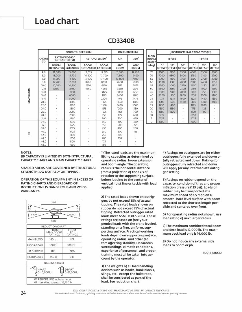
1) The rated loads are the maximum lifting capacities as determined by operating radius, boom extension and boom angle. The operating radius is the horizontal distance from a projection of the axis of rotation to the supporting surface, before loading to the center of vertical hoist line or tackle with load applied.
2) The rated loads shown on outrig-gers do not exceed 85% of actual tipping. The rated loads shown on rubber do not exceed 75% of actual tipping. Retracted outrigger rated loads meet ASME B30.5-2004. These ratings are based on freely sus-pended loads with the crane leveled, standing on a firm, uniform, sup-porting surface. Practical working loads depend on supporting surface, operating radius, and other fac-tors affecting stability. Hazardous surroundings, climatic conditions, experience of personnel, and proper training must all be taken into ac-count by the operator.
3) The weights of all load handling devices such as hooks, hook blocks, slings, etc., except the hoist rope, shall be considered as part of the load. See reduction chart.
4) Ratings on outriggers are for either outriggers fully extended and down or fully retracted and down. Ratings for outriggers fully retracted and down will apply for any intermediate outrig-ger setting.
5) Ratings on rubber depend on tire capacity, condition of tires and proper inflation pressure (125 psi). Loads on rubber may be transported at a maximum speed of 2.5 mph on a smooth, hard level surface with boom retracted to the shortest length pos-sible and centered over front.
6) For operating radius not shown, use load rating of next larger radius.
7) The maximum combined total boom and deck load is 12,000 lb. The maxi-mum deck load only is 14,000 lb.
8) Do not induce any external side loads to boom or jib.
80016880CD
NOTES:JIB CAPACITY IS LIMITED BY BOTH STRUCTURAL CAPACITY CHART AND MAIN CAPACITY CHART.
SHADED AREAS ARE GOVERNED BY STRUCTURAL STRENGTH, DO NOT RELY ON TIPPING.
OPERATION OF THIS EQUIPMENT IN EXCESS OF RATING CHARTS AND DISREGARD OF INSTRUCTIONS IS DANGEROUS AND VOIDS WARRANTY.
15˚
30˚
15˚
30˚
FRONT REAR
SIDE
SIDE
0 - 21,000 lb2-PART
0 - 10,000 lb1-PART
RIGGING CHART
WIRE ROPE: 9/16 inch diameterMin. breaking strength 36,750 lb
REDUCTION CHART
MAIN BOOMFROM
RATINGSJIB
FROM
RATINGS
MAIN BLOCK
HOOK & BALL
JIB, STOWED
JIB, DEPLOYED
140 lb
100 lb
0 lb
450 lb
N/A
100 lbs
N/A
0 lb
4.0
BOOM
ON OUTRIGGERS (lb)
MA
IN B
OO
MJI
B
BOOM
(deg)ANGLE
MAINRADIUS
(ft)
RETRACTED
5.06.08.010.012.014.016.018.020.022.024.026.028.031.034.036.038.040.0
48.046.044.042.0
4300
29002600
33003700
38755175
12001650
7001025875 600
12001400 1000
850
180024001975 1475
30003850 2875
2250
360˚
ON RUBBER (lb)
F/R
--
------
1200
10001100
157514251300
19751775
2300 700 450
-
--
---
-
-
RETRACTED F/REXTENDED 360˚
EXTENDEDBOOM
200
150175
450350250
650550
6150
1825
1075950800
15501275
27752300
34254550
8700
-
--
---
--
6150
-
-
--
--
--
-4550
8700
RETRACTED 360˚ 12 ft JIB
0˚OFFSET
72
55
30
0
15
4550
6065
OFFSET15˚
-
OFFSET30˚
-
-
OFFSET0˚
OFFSET15˚
-
OFFSET30˚
-
-
18 ft JIB
JIB STRUCTURAL CAPACITIES (lb)
70
4035
EXTENDEDBOOM
RETRACTEDBOOM ANY
BOOMANY
BOOM
20 - -25 - -
105
--
--
--
--
600500400300200150
--
350275200125
----
-
28003500
1600
1300
1200
2300
7500
57004500
3000
1500
1300
25002200
5100
41003500
2550
1400
23002000
3500
31002800
2450
1400
1100
1000
21501900
4000
32002800
2150
1300
1100
19501750
3300
27002400
1700
1300
16001500
2300
20001850
7000 4800 3400 3750 3100 2200
2000 1900 1800 1700 1600 14001775 1675 1600 1525 1450 1350
13501350 1175 11251450 1400 1275 1200
12751225 1025
1050
21,00018,00015,70012,20010,2008400
15,00014,70014,40012,20010,200
60005000
71008400
940011,500
760010,000
56007800
11,500 11,50019,62516,800
13,97513,70013,40013,400
15˚
30˚
15˚
30˚
FRONT REAR
SIDE
SIDE
0 - 21,000 lb2-PART
0 - 10,000 lb1-PART
RIGGING CHART
WIRE ROPE: 9/16 inch diameterMin. breaking strength 36,750 lb
REDUCTION CHART
MAIN BOOMFROM
RATINGSJIB
FROM
RATINGS
MAIN BLOCK
HOOK & BALL
JIB, STOWED
JIB, DEPLOYED
140 lb
100 lb
0 lb
450 lb
N/A
100 lbs
N/A
0 lb
4.0
BOOM
ON OUTRIGGERS (lb)
MA
IN B
OO
MJI
B
BOOM
(deg)ANGLE
MAINRADIUS
(ft)
RETRACTED
5.06.08.010.012.014.016.018.020.022.024.026.028.031.034.036.038.040.0
48.046.044.042.0
4300
29002600
33003700
38755175
12001650
7001025875 600
12001400 1000
850
180024001975 1475
30003850 2875
2250
360˚
ON RUBBER (lb)
F/R
--
------
1200
10001100
157514251300
19751775
2300 700 450
-
--
---
-
-
RETRACTED F/REXTENDED 360˚
EXTENDEDBOOM
200
150175
450350250
650550
6150
1825
1075950800
15501275
27752300
34254550
8700
-
--
---
--
6150
-
-
--
--
--
-4550
8700
RETRACTED 360˚ 12 ft JIB
0˚OFFSET
72
55
30
0
15
4550
6065
OFFSET15˚
-
OFFSET30˚
-
-
OFFSET0˚
OFFSET15˚
-
OFFSET30˚
-
-
18 ft JIB
JIB STRUCTURAL CAPACITIES (lb)
70
4035
EXTENDEDBOOM
RETRACTEDBOOM ANY
BOOMANY
BOOM
20 - -25 - -
105
--
--
--
--
600500400300200150
--
350275200125
----
-
28003500
1600
1300
1200
2300
7500
57004500
3000
1500
1300
25002200
5100
41003500
2550
1400
23002000
3500
31002800
2450
1400
1100
1000
21501900
4000
32002800
2150
1300
1100
19501750
3300
27002400
1700
1300
16001500
2300
20001850
7000 4800 3400 3750 3100 2200
2000 1900 1800 1700 1600 14001775 1675 1600 1525 1450 1350
13501350 1175 11251450 1400 1275 1200
12751225 1025
1050
21,00018,00015,70012,20010,2008400
15,00014,70014,40012,20010,200
60005000
71008400
940011,500
760010,000
56007800
11,500 11,50019,62516,800
13,97513,70013,40013,400
Shuttlelift CD3300 Series 25
Load distribution chart
AREA 1
2,37 m sq (25.5 sq ft) 4082 kg (9000 lb)
AREA 2
1,43 m sq (15.4 sq ft) 2268 kg (5000 lb)
Area 2
Area 1 Engine hood
Cab Hydraulic reservoir
Frame rails
1) Maximum travel speed with any or all loads - 4,0 km/h (2.5 mph)2) Loads to be transported on smooth level surfaces only. 3) Boom must be retracted and in center forward position. 4) Any combination or total of areas 1 and 2 may be used.5) Lifting is not permitted when carry deck is loaded except for load-ing and unloading carry deck.6) Rated pick and carry loads may be transported on deck area 1 pro-vided the load is cribbed directly on the frame rails.
26
Symbols glossary
Drive
RotationElectrical system
Suspension
Fuel tank capacity
Tires
Engine
Brakes
Outrigger controls
Axles Outriggers
Transmission
Frame
Steering
Lights
Boom elevation
Cab
Swing
Hydraulic system
Hoist
Boom nose
Radius
Boom extension
Boom length
Grade
Gear
Boom
Counterweight
Speed
Oil
Extension
HookblockH
Heavy duty jib

Shuttlelift CD3300 Series 27
Notes
©2013 ManitowocForm No. CD3300 Series PGPart No.08-006-2M-0714 www.manitowoccranes.com
This document is non-contractual. Constant improvement and engineering progress make it necessary that we reserve the right to make specification, equipment, and price changes without notice. Illustrations shown may include optional equipment and accessories and may not include all standard equipment.
Regional offices
ChinaShanghai, China Tel: +86 21 6457 0066Fax: +86 21 6457 4955
Greater Asia-Pacific Singapore Tel: +65 6264 1188 Fax: +65 6862 4040
Europe, Middle East, Africa Ecully, France Tel: +33 (0)4 72 18 20 20 Fax: +33 (0)4 72 18 20 00
Americas Manitowoc, Wisconsin, USA Tel: +1 920 684 6621 Fax: +1 920 683 6277
Shady Grove, Pennsylvania, USA Tel: +1 717 597 8121 Fax: +1 717 597 4062
Regional headquarters
Manitowoc Cranes
ChinaBeijingChengduGuangzhouXian
Greater Asia-PacificAustraliaBrisbaneMelbourneSydneyIndiaChennaiDelhiHyderabadPuneKoreaSeoulPhilippinesMakati CitySingapore
FactoriesBrazilPasso FundoChinaTaiAnZhangjiagangFranceCharlieuMoulinsGermanyWilhelmshavenIndiaPuneItalyNiella TanaroPortugalBaltarFânzeresUSAManitowoc Port WashingtonShady Grove
AmericasBrazilAlphavilleMexicoMonterreyChileSantiago
Europe, Middle East, AfricaFranceBaudemontCergyDecinesGermanyLangenfeldItalyLainateNetherlandsBredaPolandWarsawPortugalBaltarRussiaMoscowSouth AfricaJohannesburgU.A.E.DubaiU.K.Buckingham