Embed Size (px)
Citation preview
SHMS Optics Studies
Tanja HornJLab
JLab Hall C meeting 18 January 2008
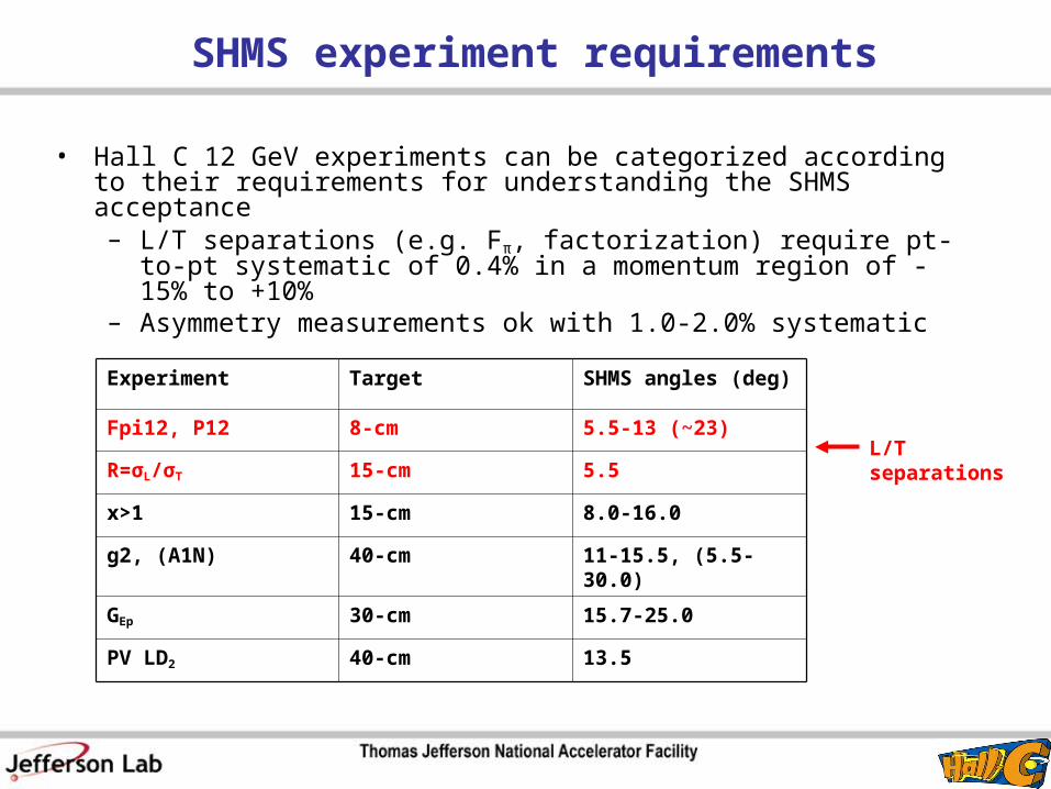
SHMS experiment requirements
• Hall C 12 GeV experiments can be categorized according to their requirements for understanding the SHMS acceptance – L/T separations (e.g. Fπ, factorization) require pt-to-pt systematic of
0.4% in a momentum region of -15% to +10% – Asymmetry measurements ok with 1.0-2.0% systematic
Experiment Target SHMS angles (deg)
Fpi12, P12 8-cm 5.5-13 (~23)
R=σL/σT 15-cm 5.5
x>1 15-cm 8.0-16.0
g2, (A1N) 40-cm 11-15.5, (5.5-30.0)
GEp 30-cm 15.7-25.0
PV LD2 40-cm 13.5
L/T separations

Context
• The purpose of the collimator is to define a geometrical acceptance in which the spectrometer optical properties are sufficiently well understood
• Acceptance depends on dp/p (δ) and target length– Characterized through event loss: Acceptance=1-loss
• Geometric effects (apertures) – well understood• Efficiency of the optical transport – more difficult to model
• Sieve slit allows for studies of the variation of optical properties over the full solid angle acceptance of the spectrometer– Populate a region simultaneously with many particle trajectories

SHMS horizontal acceptance
• Acceptance limited by well known magnet sizes and magnet gradients
• Losses before the dipole are dominated by the aperture of Q1
• The figure shows the δ dependence of the acceptance after the quadrupoles– Events in the red region fall
outside of at least one of the nominal detector apertures
– The green lines denote the acceptance determined by the nominal detector configuration
-10% < δ < +22%

SHMS collimator placement
• Design will be octagonal shape• Dimensions depend on location in z
Q1 Q2 Q3HB D
Possible sieve collimator locations
y
x
• Sieve collimator in front of HB: standard optics calibration may be complicated– Aperture defining slits: best location in front of HB
• Sieve collimator in front of Q1: optics modeling straightforward, but have to assume that perturbations due to HB are small
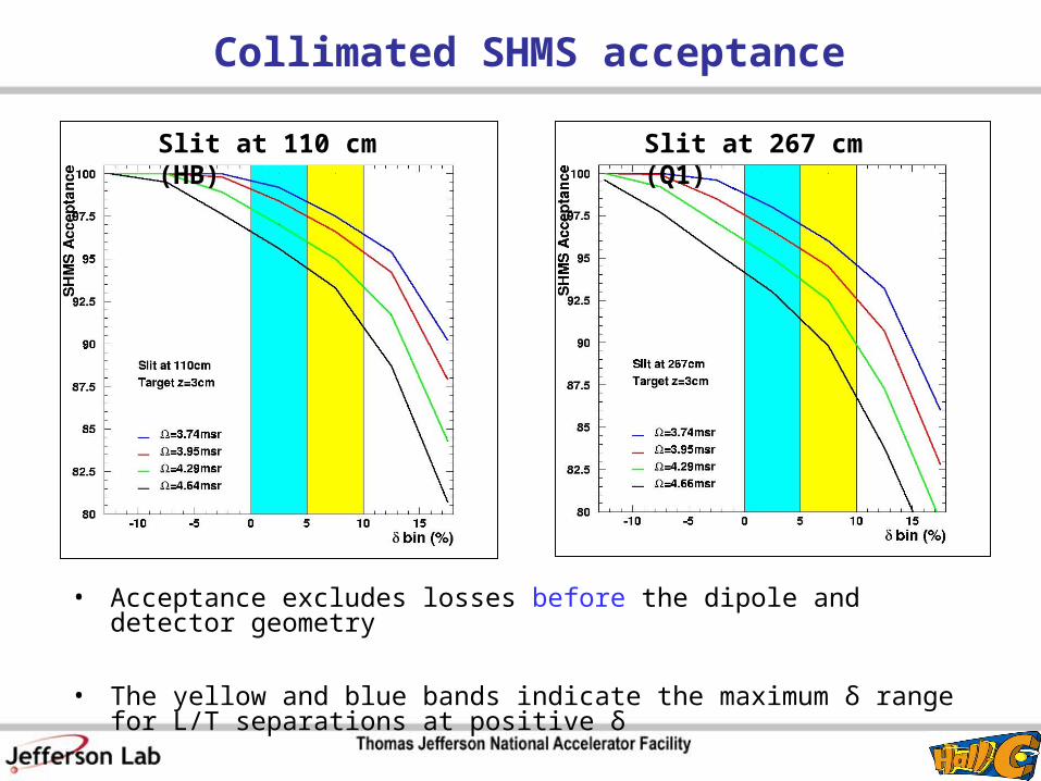
Collimated SHMS acceptance
Slit at 110 cm (HB) Slit at 267 cm (Q1)
• Acceptance excludes losses before the dipole and detector geometry
• The yellow and blue bands indicate the maximum δ range for L/T separations at positive δ

Collimator reduces uncertainties due to optics
• Event loss at Q1 due to geometric effects
• Acceptance at dipole entrance depends on aperture and δ– Events at negative δ are focused more
+10% < δ < +15%
• Collimator can eliminate events that would be lost inside the dipole– Reduces model dependent
systematic uncertainty
Q1
Q2
Q3
D

Collimated SHMS acceptance corrected for loss at the dipole entrance
• Acceptance shows losses inside the dipole and exit
• Understanding of losses inside the dipole could be improved through optics studies using actual data or precise mapping of the fields
Slit at 110 cm (HB) Slit at 267 cm (Q1)

SHMS Collimator Summary
• Small collimator could be used for L/T separations– good understanding of acceptance function
• In general, size of the collimator depends on the target length– Effective target length for all L/T separations is <3cm – May need a special small collimator for extended targets typically used in
asymmetry measurements– Large collimator also possible if rates more important than systematics
• Shape: octagonal, material: heavymet– thickness: same as for HMS (6.3cm), but still under study – dimensions in x and y depend on location in z – both locations in front of HB
and Q1 would be possible
• Mechanical design: currently fixed, but moving design may also be feasible

SHMS sieve slit design
• Size of sieve holes: 3 mrad– For comparison: HMS sieve holes diameter is 0.504cm (3 mrad)
• Further studies of the focal plane patterns will determine the optimal design for optics reconstruction
Z=110cm Z=267cm• Sieve slit is used to understand the
optics properties the spectrometer
• Figures show simulations of possible sieve hole configurations

SHMS Optics: plans
• Implement real magnets in the Monte Carlo– Current SHMS Monte Carlo uses ideal magnets
• HB field map differences – effect on optics– Initial check by J. LeRose using SNAKE– Final studies will be done using COSY after real magnets are
implemented

Study of SHMS detector sizes
• Nominal target length and angle set by approved experiments– 40cm target, 40deg
• Scattering chamber can accommodate 50cm targets
Detector Z
(cm)
Xsize
(cm)
Ysize
(cm)
Atm. Cer -310 to -60 70 80
DC1 -40 75 80
DC2 +40 85 90
C4F10 Cer +70 to +250 115 100
Calorimeter +280 to +360 130 120
Values are given for the back of the detectors
Beam envelope at selected detector locations

SHMS further studies
• SHMS horizontal bender prototype tests for radiative heating studies– Performed prototype tests in
summer 2006 • Analysis is complete• Improvement of MC requires
more data– Additional measurement near end
of GEp with improved sensitivity less than 100 mK
• Detector hut shielding– Initial estimate from PDG: 1-2m
concrete– More detailed simulation for
SHMS structure review in March 2008
SHMS 18° vertical bend
Q1Q2Q3 HBD

SHMS information updates
• Documentation about SHMS R&D and upgrade in Hall C 12 GeV database– http://www.hallcweb.jlab.org/doc-public/DocumentDatabase
• User: 12gev• Password: xxxxxxxx ([email protected] for password)
• Updates to the 12 GeV web site currently are currently located here:• http://www.jlab.org/~hornt/hallc_12gev/hallc_12gev.html
Nominal SHMS parameters
Links to:– Experiment
requirements– Document database– SHMS Optics studies
Other 12 GeV links:– Monte Carlo– Spectrometer Layout