Embed Size (px)
Citation preview
Spin dependent transport in magneticnanostructures
T. Shinjo
November 1, 2000
Contents
1 INTRODUCTION 2
2 GMR IN MULTILAYERED SYSTEMS : EXPERIMENTALASPECTS 42.1 Before the discovery of GMR . . . . . . . . . . . . . . . . . . . 42.2 The GMR effect (Fe/Cr multilayers) . . . . . . . . . . . . . . . 6
3 Other coupled-type GMR systems and interlayer coupling 83.1 Non-coupled systems (multilayers) . . . . . . . . . . . . . . . . . 103.2 Non-coupled sandwiches (Spin valve systems) . . . . . . . . . . 163.3 Extension of studies on GMR-related phenomena . . . . . . . . 173.4 Geometry of GMR . . . . . . . . . . . . . . . . . . . . . . . . . 203.5 Studies on nanomagnetic systems using GMR effect . . . . . . . 243.6 Summary . . . . . . . . . . . . . . . . . . . . . . . . . . . . . . 27
1
1 INTRODUCTION
The technical term, magnetoresistance (MR), has been used to express allkinds of electric conductivity change caused by applying a magnetic field andcovers a great variety of phenomena. For instance, the features of MR ef-fect in metallic systems are greatly different from those in semiconductors. Inferromagnetic metals and alloys, the difference of resistivity regarding to thedirection of magnetization has been known as the anisotropic magnetoresis-tance (AMR) from a long time ago. Normally the resistivity is smaller if theelectric current direction is perpendicular to the direction of magnetizationthan in the condition that those are parallel. The origin of AMR is consideredto be the orbital angular momentum of magnetic ions and also the Lorentzforce acting on conduction electrons. The relative change of resistivity (MRratio) due to the AMR effect is fairly small; a few present for Ni80Fe20 alloy(permalloy) at room temperature and somewhat larger at lower temperatures.Nevertheless, this phenomenon has a significant importance for technical ap-plications such as magnetic sensors. As illustrated in Fig. 1, if a magnet isattached on a rotating disk, an MR sensor can detect the number of rotationsor the speed of motion very easily from the resistance change of the MR sensor.It has also been attempted to apply an AMR sensor for a magnetic recordingtechnology. Using an MR read-out head, information recorded in a magneticstorage medium is directly converted into electric signals. For ultrahigh den-sity recording, a very high sensitivity of head is indispensable and thus theMR ratio is required as high as possible. However it was unlikely to find anymaterial having a large MR effect at room temperature. Some magnetic semi-conductors have been known to exhibit large MR ratios but only at low tem-peratures. Although a large MR effect at room temperature under a moderatemagnetic field is desirable from a technical viewpoint, no major success hasbeen achieved in the exploration of new MR materials, until the discovery ofthe giant magnetoresistance (GMR) effect.
[Figure 1 about here.]
The GMR effect has been observed in 1988 by Baibich et al. in the resistiv-ity measurements on Fe/Cr multilayers [1], as shown in Fig. 2. The discoveryof GMR was a great breakthrough in the field of thin film magnetism andmagneto-transport studies. At 4.2 K, the resistivity of [Fe 30A/Cr 9A] mul-tilayer was decreased by almost 50 % by applying an external field. Evenat 300 K, the decrease of resistivity reaches to 16 %, which is significantlylarger than MR changes caused by the AMR effect, and therefore the newphenomenon was named “giant”. The mechanism of GMR was promptly at-tributed to the change of the magnetic structure induced by an external field.At zero field, magnetizations in each Fe layer are aligned antiparallel, but areoriented to be parallel by applying an external field larger than 2 T. In the
2
antiparallel magnetic structure, conduction electrons are much more scatteredthan in a parallel magnetic structure. Until the discovery of GMR, it was notrealized that the spin-dependent scattering can make such a large contributionto the resistivity.In the next section, the experimental aspects of GMR effectwill be described and studies done before the GMR discovery also are brieflysurveyed.
[Figure 2 about here.]
It is easily speculated that the resistivity of a magnetic material is influ-enced by spin structures. In a textbook on magnetism, we are able to find forinstance the temperature dependence of resistivity of pure Ni metal as shown inFig. 3, which was measured more than 50 years ago. At the Curie temperatureof631 K, the resistivity curve shows a change of the temperature coefficient.The difference of gradients in ferromagnetic and paramagnetic regions is aclear evidence that the resistivity depends on the magnetic structure and theferromagnetically ordered state has a smaller resistivity. In a paramagneticregion with randomly oriented (or fluctuating) spins, conduction electrons aremore scattered by magnetic origins. Indeed, to measure the temperature de-pendence of resistivity has been known as a method to determine the magnetictransition temperature. However if you measure the temperature dependenceof resistivity for the purpose to determine the transition temperature, youwill notice that this method is not sensitive and get an impression that thecontribution of magnetism on resistivity is fairly small, because a change ofresistivity at the transition temperature is not remarkable. On the other hand,you can extend the resistivity curve in the paramagnetic region (higher thanTc) down to lower temperatures without any theoretical guidance (the dottedline in the Fig. 3), Then, you will be aware how big is the contribution of themagnetic structure to the resistivity. At room temperature for instance, theextrapolated resistivity is twice as large as the real value. This comparisonis of course non-sense because a magnetically disordered structure at roomtemperature is fictitious, but is useful to draw an image on the size of spindependent scattering. From this classic result, one could have got an idea thata large MR effect may happen if the magnetic structure can be varied.
[Figure 3 about here.]
However, at lower temperatures than Tc, it is generally impossible in normalferromagnetic materials to realize any kind of disordered spin structure, byapplying a moderate magnetic field. The GMR experiment has revealed thatthe magnetic structure in multilayers composed of ferromagnetic and non-magnetic layers can be varied by applying external fields. We have obtaineda hint here how to construct multilayers whose magnetic structures may bemodified by external magnetic fields.
3
As is described in the next chapter, the GMR effect has evidenced thatthe spin dependent scattering can induce a significantly large MR change atroom temperature. Subsequently studies on various phenomena relating to theinterplay of magnetism and transport have been very much stimulated in fun-damental and also technological aspects, and the term “magnetoresistance” hasbecome a fashionable key word. Besides metallic multilayer systems, similarphenomena are found in granular systems where small ferromagnetic clustersare dispersed in non-magnetic matrices. Extremely large MR effect has beenfound in manganese perovskite oxides and is named to be the colossal MR(CMR) effect which means to be greater than giant. Latest achievements onperovskite oxides have been described in another volume edited by Tokura inthe same monograph series as this. Currently remarkable progress has beenmade also in the studies on MR effect using tunneling currents, which is oftenabbreviated to be TMR. Detailed description on TMR will be given in otherchapters. In order to express more comprehensively the GMR including re-lated phenomena such as CMR and TMR, we may denote as “XMR” (X=G,T, C), If necessary, X may include A (i.e., AMR) also. The term, XMR cancover all novel MR effects and in addition X sounds to express our further wishto find something new and exotic.
2 GMR IN MULTILAYERED SYSTEMS : EX-
PERIMENTAL ASPECTS
2.1 Before the discovery of GMR
Pioneering works to study the dependence of conductivity on the magneticstructure have been carried out for tunneling junctions much earlier than thediscovery of GMR. A tunneling current from one ferromagnetic metal to an-other ferromagnetic one through a thin potential barrier may depend on therelative orientations of the two magnets. This idea was verified for the junc-tions of Co/Ge/Ni and Ni/NiO/Co respectively by Julliere [2], and byMaekawaand Gafvert [3]. However they have observed only small MR effect at low tem-peratures and the results did not gather intense attention at that time. In veryrecent years, there have been remarkable progresses in the studies of tunnel-ing current MR (TMR), experimentally and theoretically. Since it has beenconfirmed that a large MR ratio can be achieved at room temperature, the im-portance of TMR also for industrial sides is recognized, as will be mentionedin the forthcoming chapters.
In ferromagnetic thin films, the magnetic structures become more or lessinhomogeneous in the process of magnetization reversal and disordered mag-netic fractions, domain walls for instance, will act as sources of resistance. In aresistivity measurement as a function of external field, it is common to observe
4
an increase (or a decrease) of resistivity around the field for the magnetiza-tion reversal. An increase is attributed to the spin-dependent scattering anda decrease, AMR effect. However, in any case, variations of resistance are notvery large. Magnetic and electric behaviors of a sandwich system consistingof ferromagnetic/non-magnetic metal layers were studied by Dupas et al. [4]They prepared epitaxially grown 3 A Co layer sandwiched by two 300A Aulayers, [Au 300A/Co 3A/Au 300A], and measured the resistivity with sweep-ing the magnetic field. The resistivity showed a clear increase at the fieldof magnetization reversal such as 1 % at 300 K, and 6 % at 4.2 K. The ob-served enhancement of resistance is caused by the magnetic structure changeof monoatomic Co layer. As a magnitude of MR ratio, this value is not remark-ably large, but if we consider the thickness of the Au layers being 100 timeslarger than that of Co, the contribution of magnetism to the total conductivityappears to be significant. Whether this phenomenon is related to the preferredorientation of magnetization being perpendicular to the film plane or not stillopen question. The resistance should depend on the magnetic structure frommicroscopic viewpoints and therefore the perpendicular anisotropy may playa crucial role.
The study on the Fe/Cr/Fe sandwich system has been initiated by Grunberget al. [5] This is a preceding work very closely relating to the GMR studiesby Baibich et al. [1] In 1986, Grunberg’s group found that an antiferromag-netic exchange interaction exists between Fe layers separated by a Cr 10Alayer by measuring the hysteresis curves utilizing magneto-optic Kerr effect(MOKE) and light scattering (LS) due to spin waves. Spin polarized LEEDmeasurements by Alvarado and Carbone also confirmed the existence of anti-ferromagnetic interlayer coupling [6]. In a trilayer sample, [Fe 120A/Cr 10A/Fe120A], two Fe layers’ magnetizations are oriented antiparallel in the absenceof external field, because of the interlayer exchange coupling, but reorientedto be parallel by applying an external field larger than 0.3 T. Grunberg et al.have also measured the resistivity of Fe/Cr/Fe sandwich film with applyingexternal field and observed the difference of resistivity between the states ofparallel and antiparallel magnetizations. It has been clearly evidenced that theconductance is influenced by the magnetic structure due to the spin dependentscattering of conduction electrons [7]. Thus, the physical principle of GMR wasalready demonstrated in this experiment. However, the observed MR ratio,about 1.5 % at low temperatures, was not so large to gather attention widelyas a discovery of new MR effect.
In the research on metallic magnetic systems, one of major problems hasbeen the long range exchange interactions acting between two local mag-netic impurities. The Ruderman-Kittel-Kasuya-Yosida (RKKY) interactionhas been known to be the mechanism to account for long range interactionsthrough conduction electrons. However, interactions between impurities arerather weak, and therefore were the subjects in the field of low temperature
5
physics. Until the Fe/Cr/Fe studies, exchange interactions between magneticlayers with a distance as 10A was thought to be fairly weak. Although alreadymany kinds of multilayers consisting of magnetic and non-magnetic compo-nents had been studied,we have hardly imaged such a magnetic structure thatmagnetizations in adjacent layers are oriented entirely antiparallel by the in-terlayer coupling [8]. Nearly at the same time with the Fe/Cr/Fe studies, butindependently, Cebollada et al. confirmed by neutron diffraction techniquethat an antiparallel magnetic structure is realized in Co/Cu multilayers [9].This is the first confirmation of the antiparallel alignment of magnetizationsin a multilayer systems.
2.2 The GMR effect (Fe/Cr multilayers)
Baibich et al. prepared Fe/Cr multilayered films by MBE technique initiallyto study in more details the magnetic behaviors of the multilayer system withantiferromagnetic interlayer coupling. The samples with a structure for in-stance, [Fe 30A/Cr 9A]×60, were deposited on GaAs (001) substrates and theepitaxial stacking of Fe(001)/Cr(001) was confirmed [1]. The magnetizationcurves for samples with various Cr layer thicknesses are also shown in Fig. 2, inthe preceding chapter. By applying external field, the resistivity has decreasedgreatly. At the saturation field, the resistivity is almost a half of that at zerofield, which was an unexpectedly large magnetoresistance effect for metallicsubstances. The mechanism of the GMR effect was phenomenologically inter-preted by considering the spin-dependent scattering of conduction electrons.It is assumed that the scattering probability depends on the relation betweenconduction electrons’ spin direction, up or down, and the directions of mag-netization in magnetic layers. For instance, an up-spin electron is consideredto penetrate without scattering from Cr layer into Fe layer having magneti-zation with the up-spin direction, while a down-spin electron is scattered. IfFe layers’ magnetizations are antiparallel, both up- and down-spin electronswill meet an Fe layer with magnetization of opposite direction soon (withintwo Fe layers’ distance) and accordingly have a rather high possibility to bescattered. On the other hand, if all the Fe layers’ magnetizations are parallel,down-spin electrons are scattered at every Fe layer while up-spin electrons arenot, having a long mean-free path. As a total of conductivities due to up-spinand down-spin currents, the state with parallel magnetizations has a muchbetter conductivity than that with antiparallel magnetizations. Explanationof spin- dependent scattering from theoretical aspects is given in text books[10] and also in the theoretical chapter of this volume.
From the discovery of the GMR effect, we have learnt the following. (1)Spin-dependence scattering can make a significantly large contribution to thetotal resistance. (2) An interlayer coupling exists between ferromagnetic layersseparated by a spacing layer, which can be fairly strong. The magnetization
6
measurements shown in Fig. 2 suggest the existence of magnetic structurewith antiparallel alignment. The external field for saturation increases withthe decrease of the Cr layer thickness. The sample with 9A Cr layers showsvery slow increase of magnetization when the external field increases. Theantiferromagnetic coupling between adjacent ferromagnetic Fe layers seems tobe very strong. A more direct evidence of the antiparallel alignment of Felayers’ magnetizations was given by observing a neutron diffraction peak dueto the antiparallel superstructure [10]. The neutron diffraction peak of anFe/Cr multilayer, shown in Fig. 4, corresponds to the twice of the adjacent Felayer distance, and therefore clearly indicates the antiparallel alignment of Felayer magnetizations. The intensity of the peak decreases with the increaseof external field and it disappears at around 0.4 T. The field dependence ofthe peak intensity is shown in the figure, together with the change of themagnetization and resistivity. It is apparent from the comparison that theGMR effect in Fe/Cr multilayers is caused by the antiparallel alignment ofmagnetic layers.
[Figure 4 about here.]
In general, it is possible to observe a GMR-type resistivity difference notonly between parallel and antiparallel magnetic states, but also between ferro-magnetically aligned states and any disordered states. The GMR effect ingran-ular systems to be mentioned later is the difference of resistivity between theparallel and the randomized spin structures. As for spin structure, an antipar-allel alignment is one of the perfectly ordered state but concerning the spindependent scattering for conduction electrons, an antiparallel state is equiva-lent to a disordered state. The result on Fe/Cr multilayers has revealed that asignificantly large MR effect, which may be much larger than the classic AMReffect, is realized if the magnetic spin structure is able to be varied as desired.However, in the case of Fe/Cr multilayers, the externally applied fields ratherlarge, in the order of 0.1 T or more, in order to overcome the antiferromagneticinterlayer coupling. Therefore at the initial stage the potential of the GMReffect for technical applications did not appear to be very promising. In theinitial report on the GMR effect in Fe/Cr multilayers by Baibich et al. [1], theresistivity at zero field is defined to be 100 % and the decrease of resistivity isexpressed relative to the value at zero field. The resistivity becomes a constantif the magnetization has saturated. Here, all magnetizations are regarded tobe entirely parallel and the spin-dependent scattering due to disordered mag-netic structures does not exist. The resistivity at the saturated state shouldregarded as a basic value where the contribution from spin disorder is mini-mized. Therefore it makes sense to express the resistivity relative to the valueat the saturated region and after a while, it has become common to expressthe GNR ratio relative to the value at saturation, instead of that at zero field,
7
i.e.,
MR ratio (%) =[R(H)− R(saturation)]× 100
R(saturation)(1)
where R(H) means the resistivity under external field, H . In this manner, theMR ratios of the Fe/Cr multilayer at 4,2 K and 300 K in the original reporthave turned out to be 85 % and 19 %, respectively. At lower temperatures,the resistivity of metals due to electron-phonon interaction should decrease.In contrast, the contribution due to the spin-dependent scattering does notdecrease at low temperatures. In the case of GMR effect, an MR ratio meansthe relative size of magnetic resistance to the total. Therefore the MR ratioincreases with a decrease of temperature. In a later report, the MR ratioof Fe/Cr multilayers at very low temperature has attained to 200 % [11].Nowadays almost all MR results are shown relative to the saturated value butif the saturation field is very large, the resistivity at the saturated state is noteasily estimated experimentally and for the convenience the resistance changeis expressed relative to the zero field value. Such examples, having very largesaturation fields, are often seen in granular systems.
Since the discovery of GMR effect, interlayer couplings between ferromag-netic layers across a non-magnetic intervening layer has gathered attentionand various studies have been intensely carried out even independently of theinterest in GMR. As will be described later, the role of non-magnetic spacerlayer is crucial to account for the interlayer coupling between ferromagneticlayers. In the last decade, many experimental and theoretical studies havebeen performed for magnetic/non-magnetic/magnetic systems, primarily forthe purpose to investigate the condition to enhance the MR ratio [12]. Con-sequently, the GMR discovery has played as a great breakthrough and theinfluence has extended widely to various fields. Our understanding of the elec-tronic structure in ultrathin metal films has greatly progressed and for instancethe existence of quantum well states in metallic layers have been elucidated[13].
3 Other coupled-type GMR systems and in-
terlayer coupling
Studies on multilayers consisting of magnetic and non-magnetic layers havebeen stimulated by the GMR effect found in Fe/Cr multilayers. The exis-tence of interlayer coupling was confirmed in many systems and it has beenobserved that an antiparallel magnetic alignment generally has a larger resis-tivity than a parallel (ferromagnetically aligned) state. However the MR ratiois not always very large but depends on the combinations of magnetic andnon-magnetic substances. Among magnetic/non-magnetic multilayers, a par-ticularly interesting system is Co/Cu multilayers, of which MR behaviors were
8
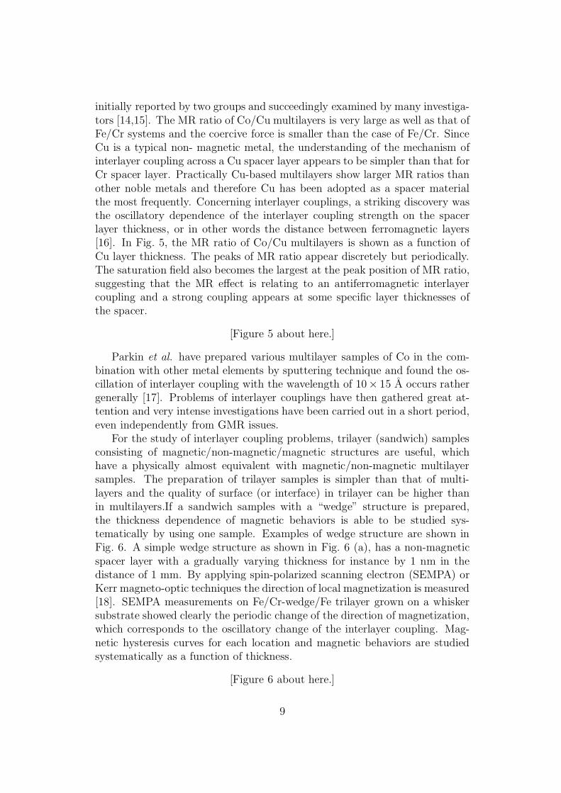
initially reported by two groups and succeedingly examined by many investiga-tors [14,15]. The MR ratio of Co/Cu multilayers is very large as well as that ofFe/Cr systems and the coercive force is smaller than the case of Fe/Cr. SinceCu is a typical non- magnetic metal, the understanding of the mechanism ofinterlayer coupling across a Cu spacer layer appears to be simpler than that forCr spacer layer. Practically Cu-based multilayers show larger MR ratios thanother noble metals and therefore Cu has been adopted as a spacer materialthe most frequently. Concerning interlayer couplings, a striking discovery wasthe oscillatory dependence of the interlayer coupling strength on the spacerlayer thickness, or in other words the distance between ferromagnetic layers[16]. In Fig. 5, the MR ratio of Co/Cu multilayers is shown as a function ofCu layer thickness. The peaks of MR ratio appear discretely but periodically.The saturation field also becomes the largest at the peak position of MR ratio,suggesting that the MR effect is relating to an antiferromagnetic interlayercoupling and a strong coupling appears at some specific layer thicknesses ofthe spacer.
[Figure 5 about here.]
Parkin et al. have prepared various multilayer samples of Co in the com-bination with other metal elements by sputtering technique and found the os-cillation of interlayer coupling with the wavelength of 10× 15 A occurs rathergenerally [17]. Problems of interlayer couplings have then gathered great at-tention and very intense investigations have been carried out in a short period,even independently from GMR issues.
For the study of interlayer coupling problems, trilayer (sandwich) samplesconsisting of magnetic/non-magnetic/magnetic structures are useful, whichhave a physically almost equivalent with magnetic/non-magnetic multilayersamples. The preparation of trilayer samples is simpler than that of multi-layers and the quality of surface (or interface) in trilayer can be higher thanin multilayers.If a sandwich samples with a “wedge” structure is prepared,the thickness dependence of magnetic behaviors is able to be studied sys-tematically by using one sample. Examples of wedge structure are shown inFig. 6. A simple wedge structure as shown in Fig. 6 (a), has a non-magneticspacer layer with a gradually varying thickness for instance by 1 nm in thedistance of 1 mm. By applying spin-polarized scanning electron (SEMPA) orKerr magneto-optic techniques the direction of local magnetization is measured[18]. SEMPA measurements on Fe/Cr-wedge/Fe trilayer grown on a whiskersubstrate showed clearly the periodic change of the direction of magnetization,which corresponds to the oscillatory change of the interlayer coupling. Mag-netic hysteresis curves for each location and magnetic behaviors are studiedsystematically as a function of thickness.
[Figure 6 about here.]
9
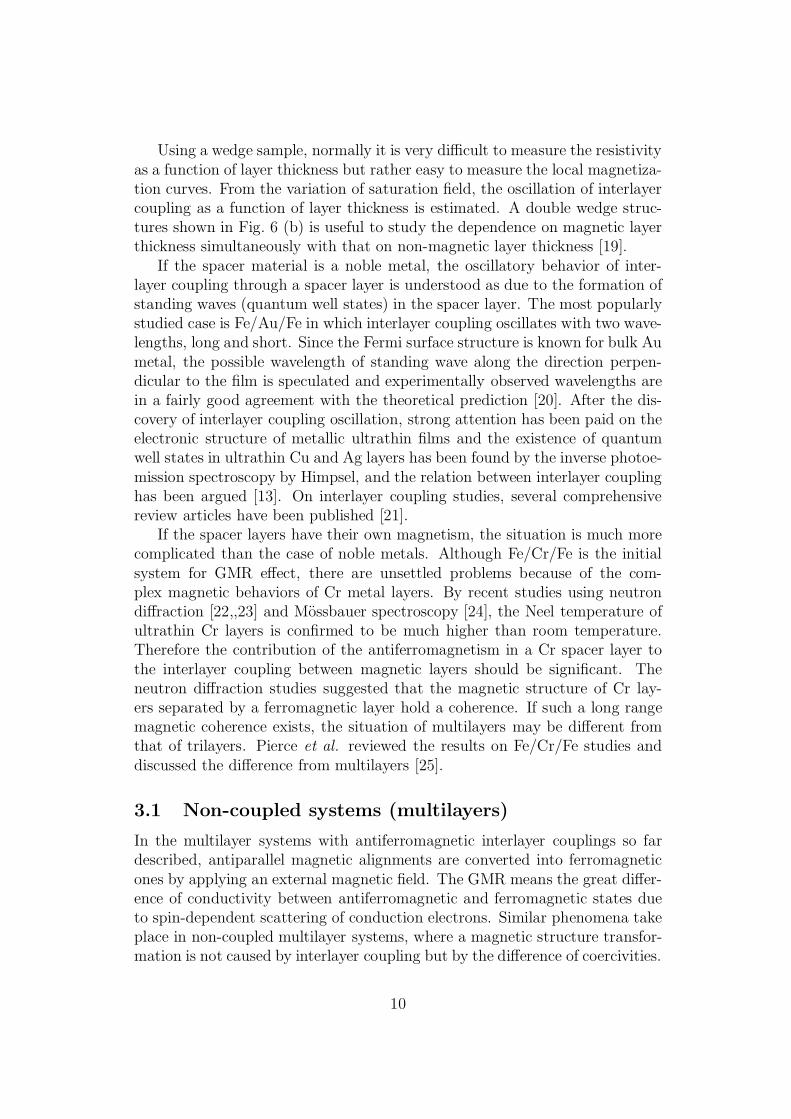
Using a wedge sample, normally it is very difficult to measure the resistivityas a function of layer thickness but rather easy to measure the local magnetiza-tion curves. From the variation of saturation field, the oscillation of interlayercoupling as a function of layer thickness is estimated. A double wedge struc-tures shown in Fig. 6 (b) is useful to study the dependence on magnetic layerthickness simultaneously with that on non-magnetic layer thickness [19].
If the spacer material is a noble metal, the oscillatory behavior of inter-layer coupling through a spacer layer is understood as due to the formation ofstanding waves (quantum well states) in the spacer layer. The most popularlystudied case is Fe/Au/Fe in which interlayer coupling oscillates with two wave-lengths, long and short. Since the Fermi surface structure is known for bulk Aumetal, the possible wavelength of standing wave along the direction perpen-dicular to the film is speculated and experimentally observed wavelengths arein a fairly good agreement with the theoretical prediction [20]. After the dis-covery of interlayer coupling oscillation, strong attention has been paid on theelectronic structure of metallic ultrathin films and the existence of quantumwell states in ultrathin Cu and Ag layers has been found by the inverse photoe-mission spectroscopy by Himpsel, and the relation between interlayer couplinghas been argued [13]. On interlayer coupling studies, several comprehensivereview articles have been published [21].
If the spacer layers have their own magnetism, the situation is much morecomplicated than the case of noble metals. Although Fe/Cr/Fe is the initialsystem for GMR effect, there are unsettled problems because of the com-plex magnetic behaviors of Cr metal layers. By recent studies using neutrondiffraction [22,,23] and Mossbauer spectroscopy [24], the Neel temperature ofultrathin Cr layers is confirmed to be much higher than room temperature.Therefore the contribution of the antiferromagnetism in a Cr spacer layer tothe interlayer coupling between magnetic layers should be significant. Theneutron diffraction studies suggested that the magnetic structure of Cr lay-ers separated by a ferromagnetic layer hold a coherence. If such a long rangemagnetic coherence exists, the situation of multilayers may be different fromthat of trilayers. Pierce et al. reviewed the results on Fe/Cr/Fe studies anddiscussed the difference from multilayers [25].
3.1 Non-coupled systems (multilayers)
In the multilayer systems with antiferromagnetic interlayer couplings so fardescribed, antiparallel magnetic alignments are converted into ferromagneticones by applying an external magnetic field. The GMR means the great differ-ence of conductivity between antiferromagnetic and ferromagnetic states dueto spin-dependent scattering of conduction electrons. Similar phenomena takeplace in non-coupled multilayer systems, where a magnetic structure transfor-mation is not caused by interlayer coupling but by the difference of coercivities.
10

Multilayers including two magnetic components with different coercivities wereprepared by stacking NiFe, Cu, Co and Cu, succeedingly [26]. If the thicknessof Cu spacer is not too thin, magnetic layers are isolated with each other andtwo magnetic components show the reversal of each magnetization indepen-dently. In Fig. 7, the magnetization curve of [NiFe 30A/Cu 50A/Co 30A/Cu50A]×15 at 300 K is reproduced. The curve is the sum of the two magnetiza-tions in NiFe and Co layers. NiFe is a typical soft magnetic material having asmall coercivity while Co has a much larger one. The switching fields of NiFeand Co layers are observed to be about 10 and 100 Oe, respectively.
[Figure 7 about here.]
An external field enough to orient both magnetizations in the field directionwas first applied and then the magnetization and resistivity was measured withvarying external field. If the field exceeds Hc(NiFe), the magnetization of NiFelayers turns to the direction of the external field but that of Co layers remainsunchanged until Hc(Co). Eventually, two magnetizations are expected to beantiparallel between Hc(NiFe) and Hc(Co). The change of magnetic structureinfluences the resistivity greatly and a remarkable enhancement of resistivityis observed in the field region between Hc(NiFe) and Hc(Co). Apparently theGMR effect is working also ina non-coupled multilayer system. The resistivityvs field curve shows a rather sharp peak. If both the reversals of two magneti-zations occur suddenly, a plateau should have been observed but because themagnetization reversal in the Co layers is gradual, the profile becomes not aplateau but a peak. It is general that a magnetization is gradually reversedwith forming domain structures. Afterwards, in many cases, plateau-type MRprofiles have been found,for example in wire-shaped systems where the domainwall formation is controlled [27].
In the case of the non-coupled GMR system also, it was confirmed by ob-serving a superstructure peak of neutron diffraction that the majority of mag-netic structure is antiparallel [28]. The GMR effect observed here is regardedas the difference of resistivity between a parallel and an antiparallel magneticstate. From this experiment, several suggestions are obtained. For the GMReffect, interlayer couplings are not a necessary condition but magnetic struc-tural changes by any reason may cause an MR effect. It is of practical impor-tance that the working field is fairly small. In contrast to the coupled systems,where a large field is required to overcome the interlayer coupling, non-coupledsystems require only a moderate field. If one component is very soft having asmall switching field, the MR effect is exhibited in very weak fields. From theobservation of non-coupled type GMR effect, the potential of the GMR effectfor technical applications has been recognized to be very promising. Actually agreat success for technical use has been achieved in sandwich system includingtwo magnetic layers, which was named “spin valve” [29]. The description onspin valve systems will be given in the next section.
11
Non-coupled multilayer systems are useful for various experiments to studythe fundamental aspects of GMR phenomena. Antiparallel magnetic structuresare easily realized for every case regardless to the thickness of spacer layer,unless it is too thin. In contrast, in coupled systems, the interlayer couplingworks strongly only at certain spacings. Because an antiparallel alignmentis realized at specified thicknesses, the relation between MR ratio and thespacer layer thickness, for instance, cannot be studied continuously. On theother hand, in non-coupled systems, an antiparallel alignment is realized atany spacer layer thickness. In addition, in the latter case, not only collinearalignments but also non-collinear magnetic structures are realized. An exampleis shown in Fig. 9. Taking the advantage of non-coupled type systems, severalinvestigations were carried out.
[Figure 8 about here.]
In contrast to the AMR effect, which means the difference of resistivityregarding to the direction of magnetization, the GMR does not depend on thedirection of the magnetic field, which is verified experimentally by measuringthe GMR ratio of [NiFe/Cu/Co/Cu] as a function of the relative angle betweenthe magnetic field and the current directions. Then the observed MR ratio wasfound to depend only slightly on the angle (about 0.5 % in the present case).Although NiFe layers exhibit a rather large AMR effect, the influence to thetotal MR behaviors is fairly small since the majority of electric current flows inCu layers of the [NiFe/Cu/Co/Cu] multilayer and therefore the contributionof the AMR effect in NiFe layers to the total MR effect is not significant.
[Figure 9 about here.]
By utilizing non-coupled type GMR multilayers, it is possible to check ex-perimentally the dependence of GMR on the relative angle between magnetiza-tions in adjacent layers [30]. For the spin-dependent scattering, the antiparallelalignment of magnetizations is the optimum situation and the spin-dependentscattering probability will decrease with cos θ where theta expresses the rela-tive angle between two magnetizations. The MR effect of [NiFe/Cu/Co/Cu]was measured by changing the relative angle between magnetizations in NiFeand Co layers. Namely a moderate external field, which is enough strong toreorient the magnetization of NiFe layers but too weak for the reorientation ofCo layers’ magnetization, was applied in various directions. Figure 10 is theresistance of [NiFe 25A/Cu 100A/Co 25A/Cu 100A]×15 measured by chang-ing the direction of external field, 20 Oe. In this case, the Cu layer thickness,100 A, is sufficiently large to isolate each magnetic layer. After applying anexternal field in a certain direction for the saturation, the angle dependencewas measured. The result is shown as a function of relative angle between thedirections of the initial magnetic field and the rotating field of 20 Oe. The
12
direction of Co layers’ magnetization should be the same as that of the ini-tial magnetic field while the direction of NiFe layers’ magnetization is thoughtto follow that of rotating field. As shown in the figure, the obtained resultis simulated well by a cosine curve as expected. Thus, it is proved that theprobability of spin dependent scattering is proportional to cos θ, where θ isthe relative angle between magnetizations in adjacent magnetic layers. Morestrictly speaking, the obtained curve in Fig. 10 shows a minor deviation froman ideal cosine function but is accounted for with assuming a contribution ofAMR effect in NiFe layers whose magnitude is 1/60 of the whole MR effect.The result in Fig. 10 (b) was obtained for a similar sample with a thinnerCu layers, 55A. The obtained curve has a distorted profile from an ideal co-sine function and the reason is thought to be the Cu spacer layer thicknessbeing insufficient for magnetic insulation. If a magnetic interaction from Colayers extends to NiFe layers, the magnetization in NiFe layers does not fol-low completely the rotating external field. If a magnetic field induced by themagnetization in Co layers is assumed to exist at NiFe layers, the effectivemagnetic field acting at a NiFe layer should be a vector sum of the externalfield, 20 Oe, and the stray field. By assuming the stray field in the directionof Co layer’s magnetization with various magnitudes, expected behaviors ofresistance as a function of the relative angle of external field are obtained asthe curves in Fig. 9 (b). Compared with the experimental results (dots in thefigure), it is found that 6 8 Oe gives a reasonably good fitting. This resultmeans that the magnetic influence at NiFe layer from Co layers separated by55 A Cu spacer layer corresponds to about 7 Oe. As a magnitude of magneticfield, this value is small but not negligible. The origin should be a sum ofseveral contributions; dipole field, exchange field due to conduction electronpolarization and also direct coupling if any pin holes exist. Here presented isan experimental result, which should depend on the sample. It is not certifiedthat the conclusion has a general meaning or not.
In non-coupled type multilayers, the spacer layer has to be enough thickto reduce the interlayer coupling between magnetic layers. Unless magneticlayers are able to switch the direction of magnetization independently, an-tiparallel magnetizations are not realized and subsequently non-coupled typeGMR phenomena do not take place. If the spacer layer is very thick on theother hand, magnetic insulation should be certified but the magnitude of theMR ratio cannot be very large. The MR ratio may be the maximum when thespacer layer thickness is the smallest. The MR ratio as a function of the spacerlayer thickness has been checked for three metals, Cu,Ag and Au [31]. Thesematerials are typical novel metals often used as non-magnetic spacer layers. Itis shown in Fig. 11 that Cu gives the best result. Although the MR ratio inAg-based films is larger in the region of thick spacer layers, the maximum is notlarger than that of Cu-based films because the critical thickness for Ag-basedfilms, where the interlayer coupling appears, is larger than that of Cu-based
13
films. Perhaps this result is not due to the intrinsic electronic structures of themetals but is owing to the quality of actually prepared interfaces. In Ag-basedfilms, a ferromagnetic interaction is observed if the Ag layer thickness is small,which suggests the existence of pin holes. In general, the quality of interfacescan be better in three layer (spin-valve) systems than that of multilayers.
[Figure 10 about here.]
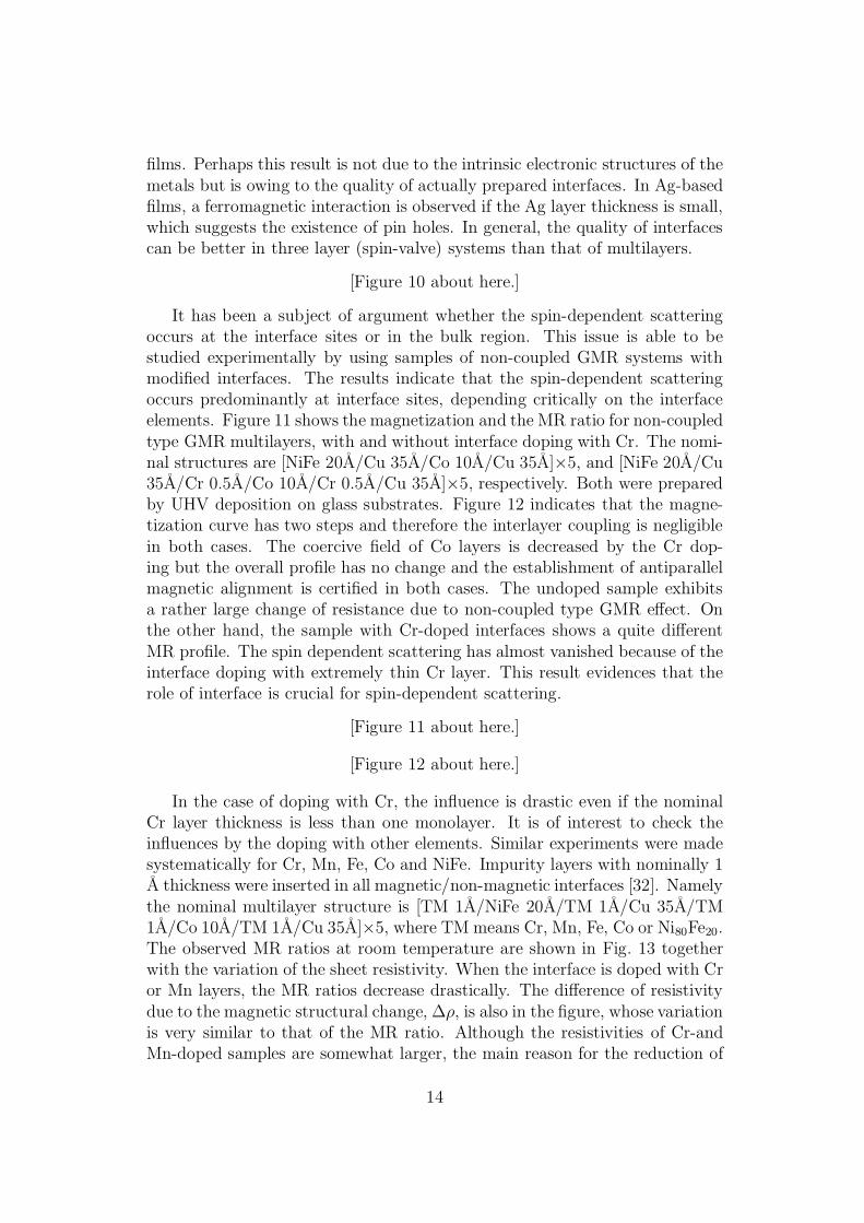
It has been a subject of argument whether the spin-dependent scatteringoccurs at the interface sites or in the bulk region. This issue is able to bestudied experimentally by using samples of non-coupled GMR systems withmodified interfaces. The results indicate that the spin-dependent scatteringoccurs predominantly at interface sites, depending critically on the interfaceelements. Figure 11 shows the magnetization and the MR ratio for non-coupledtype GMR multilayers, with and without interface doping with Cr. The nomi-nal structures are [NiFe 20A/Cu 35A/Co 10A/Cu 35A]×5, and [NiFe 20A/Cu35A/Cr 0.5A/Co 10A/Cr 0.5A/Cu 35A]×5, respectively. Both were preparedby UHV deposition on glass substrates. Figure 12 indicates that the magne-tization curve has two steps and therefore the interlayer coupling is negligiblein both cases. The coercive field of Co layers is decreased by the Cr dop-ing but the overall profile has no change and the establishment of antiparallelmagnetic alignment is certified in both cases. The undoped sample exhibitsa rather large change of resistance due to non-coupled type GMR effect. Onthe other hand, the sample with Cr-doped interfaces shows a quite differentMR profile. The spin dependent scattering has almost vanished because of theinterface doping with extremely thin Cr layer. This result evidences that therole of interface is crucial for spin-dependent scattering.
[Figure 11 about here.]
[Figure 12 about here.]
In the case of doping with Cr, the influence is drastic even if the nominalCr layer thickness is less than one monolayer. It is of interest to check theinfluences by the doping with other elements. Similar experiments were madesystematically for Cr, Mn, Fe, Co and NiFe. Impurity layers with nominally 1A thickness were inserted in all magnetic/non-magnetic interfaces [32]. Namelythe nominal multilayer structure is [TM 1A/NiFe 20A/TM 1A/Cu 35A/TM1A/Co 10A/TM 1A/Cu 35A]×5, where TM means Cr, Mn, Fe, Co or Ni80Fe20.The observed MR ratios at room temperature are shown in Fig. 13 togetherwith the variation of the sheet resistivity. When the interface is doped with Cror Mn layers, the MR ratios decrease drastically. The difference of resistivitydue to the magnetic structural change, ∆ρ, is also in the figure, whose variationis very similar to that of the MR ratio. Although the resistivities of Cr-andMn-doped samples are somewhat larger, the main reason for the reduction of
14
the MR ratio is apparently the disappearance of spin-dependent scattering.The variation of the values on the elements shown in the figure indicates thatthe maximum of the MR ratio is given by the doping with Co and the MRratio becomes almost zero for Cr-doping. This tendency is consistent withtheoretical predictions on the MR effect of Cu/TM multilayers [33]. It ishowever impressive that a submonolayer located at an interface plays such acritical role. It is worth to emphasize that GMR properties depend greatly onthe situation of interface.
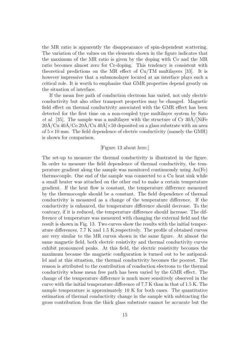
If the mean free path of conduction electrons has varied, not only electricconductivity but also other transport properties may be changed. Magneticfield effect on thermal conductivity associated with the GMR effect has beendetected for the first time on a non-coupled type multilayer system by Satoet al. [35]. The sample was a multilayer with the structure of Cr 30A/[NiFe20A/Cu 40A/Co 20A/Cu 40A]×50 deposited on a glass substrate with an areaof 5×10 mm. The field dependence of electric conductivity (namely the GMR)is shown for comparison.
[Figure 13 about here.]
The set-up to measure the thermal conductivity is illustrated in the figure.In order to measure the field dependence of thermal conductivity, the tem-perature gradient along the sample was monitored continuously using Au(Fe)thermocouple. One end of the sample was connected to a Cu heat sink whilea small heater was attached on the other end to make a certain temperaturegradient. If the heat flow is constant, the temperature difference measuredby the thermocouple should be a constant. The field dependence of thermalconductivity is measured as a change of the temperature difference. If theconductivity is enhanced, the temperature difference should decrease. To thecontrary, if it is reduced, the temperature difference should increase. The dif-ference of temperature was measured with changing the external field and theresult is shown in Fig. 13. Two curves show the results with the initial temper-ature differences, 7.7 K and 1.5 K,respectively. The profile of obtained curvesare very similar to the MR curves shown in the same figure. At almost thesame magnetic field, both electric resistivity and thermal conductivity curvesexhibit pronounced peaks. At this field, the electric resistivity becomes themaximum because the magnetic configuration is turned out to be antiparal-lel and at this situation, the thermal conductivity becomes the poorest. Thereason is attributed to the contribution of conduction electrons to the thermalconductivity whose mean free path has been varied by the GMR effect. Thechange of the temperature difference is much more sensitively observed in thecurve with the initial temperature difference of 7.7 K than in that of 1.5 K. Thesample temperature is approximately 10 K for both cases. The quantitativeestimation of thermal conductivity change in the sample with subtracting thegross contribution from the thick glass substrate cannot be accurate but the
15
change of thermal conductance in the sample due to the magnetic origin wasroughly estimated to be 45 %. Here it is evidenced that a novel variation ofthe GMR effect in multilayers is the magnetic field-dependent thermal conduc-tivity. A sizable field dependence of thermal conductivity is observed also athigher temperatures, 80 and 300 K, but a potential for technical applicationsis not clear. The change of conductivity caused by the magnetic field appearsto be too small to use for any technical purposes.
[Figure 14 about here.]
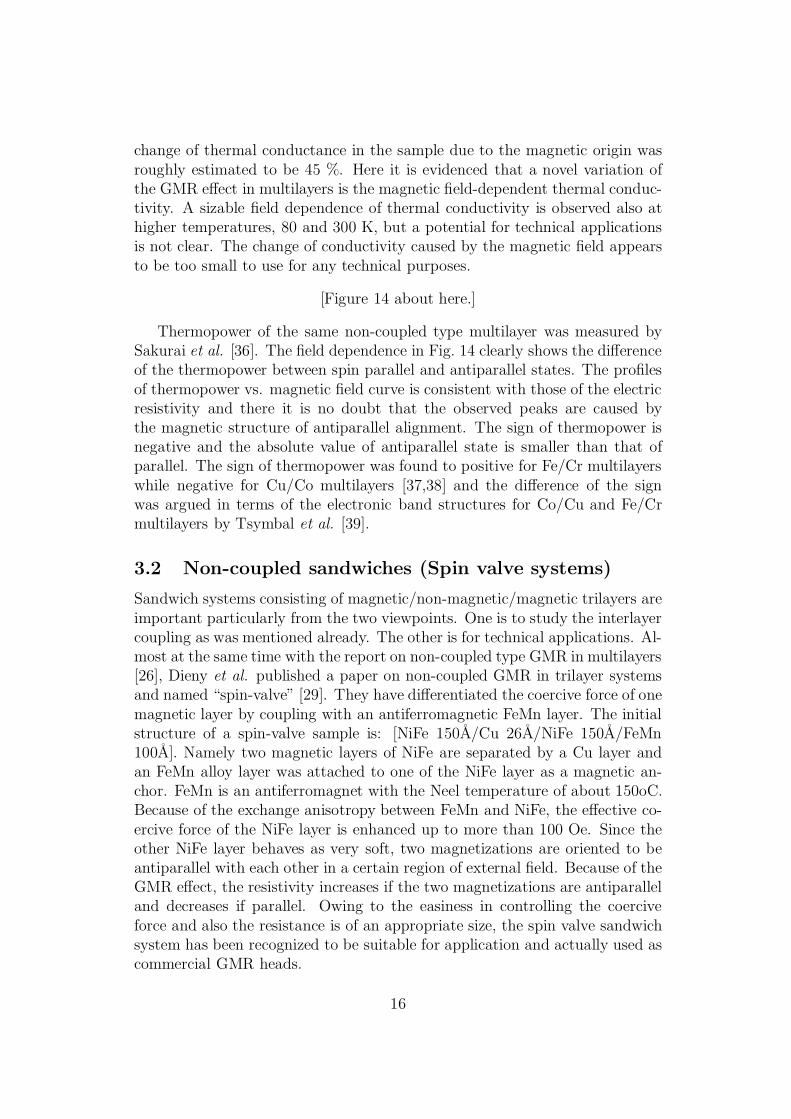
Thermopower of the same non-coupled type multilayer was measured bySakurai et al. [36]. The field dependence in Fig. 14 clearly shows the differenceof the thermopower between spin parallel and antiparallel states. The profilesof thermopower vs. magnetic field curve is consistent with those of the electricresistivity and there it is no doubt that the observed peaks are caused bythe magnetic structure of antiparallel alignment. The sign of thermopower isnegative and the absolute value of antiparallel state is smaller than that ofparallel. The sign of thermopower was found to positive for Fe/Cr multilayerswhile negative for Cu/Co multilayers [37,38] and the difference of the signwas argued in terms of the electronic band structures for Co/Cu and Fe/Crmultilayers by Tsymbal et al. [39].
3.2 Non-coupled sandwiches (Spin valve systems)
Sandwich systems consisting of magnetic/non-magnetic/magnetic trilayers areimportant particularly from the two viewpoints. One is to study the interlayercoupling as was mentioned already. The other is for technical applications. Al-most at the same time with the report on non-coupled type GMR in multilayers[26], Dieny et al. published a paper on non-coupled GMR in trilayer systemsand named “spin-valve” [29]. They have differentiated the coercive force of onemagnetic layer by coupling with an antiferromagnetic FeMn layer. The initialstructure of a spin-valve sample is: [NiFe 150A/Cu 26A/NiFe 150A/FeMn100A]. Namely two magnetic layers of NiFe are separated by a Cu layer andan FeMn alloy layer was attached to one of the NiFe layer as a magnetic an-chor. FeMn is an antiferromagnet with the Neel temperature of about 150oC.Because of the exchange anisotropy between FeMn and NiFe, the effective co-ercive force of the NiFe layer is enhanced up to more than 100 Oe. Since theother NiFe layer behaves as very soft, two magnetizations are oriented to beantiparallel with each other in a certain region of external field. Because of theGMR effect, the resistivity increases if the two magnetizations are antiparalleland decreases if parallel. Owing to the easiness in controlling the coerciveforce and also the resistance is of an appropriate size, the spin valve sandwichsystem has been recognized to be suitable for application and actually used ascommercial GMR heads.
16
In the case of spin valve systems, antiferromagnetic layers are required tobe rather thick and it is hard to repeat the deposition to make multilayers.Therefore spin valve samples are in principle sandwiches practically includingonly two magnetic layers. Initially it was thought to be inevitable that the MRratio of a sandwich is smaller than that of a multilayer. However, recently therehave been many reports that the MR ratio can be significantly enhanced inspin valve systems with sophisticated structures. In a sandwich structure, con-duction electrons meet surfaces many times, and scatterings by non-magneticorigins at surfaces and interfaces will reduce the effective MR ratio. If surfaces(and interfaces) act as mirrors and electrons are reflected specularly, there isno increase of the background resistivity and thus no loss of the MR ratio.Egelhoff et al. [40] and other recent papers [41] reported that using specu-larly reflecting layers, the MR ratio is kept to be fairly large. 20 % at roomtemperature. The specular reflectivity greatly depends on the material andthe quality of the layer and for example oxide layers (e.g., Fe2O3) are used asspecular layers. It was also reported that oxide layers with the thickness of afew A inserted in a magnetic layer works as a reflective layer and subsequentlyenhance the MR ratio [42]. In order to enhance the coercivity of pinning layer,Co/Ru/Co/Fe2O3 structure is very effective. The interlayer antiferromagneticcoupling between Co layers across a Ru layer is known to be very strong andthe cancellation of magnetization using the Co/Ru/Co structure can increasegreatly the coercivity of the pinning layer. In this structure, an Fe2O3 layer isexpected to behave as a specular reflective layer and an antiferromagnet witha high Neel temperature.
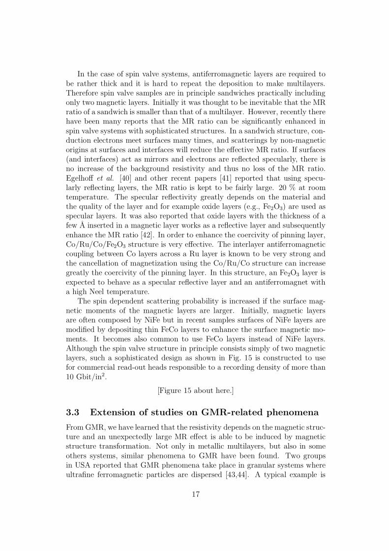
The spin dependent scattering probability is increased if the surface mag-netic moments of the magnetic layers are larger. Initially, magnetic layersare often composed by NiFe but in recent samples surfaces of NiFe layers aremodified by depositing thin FeCo layers to enhance the surface magnetic mo-ments. It becomes also common to use FeCo layers instead of NiFe layers.Although the spin valve structure in principle consists simply of two magneticlayers, such a sophisticated design as shown in Fig. 15 is constructed to usefor commercial read-out heads responsible to a recording density of more than10 Gbit/in2.
[Figure 15 about here.]
3.3 Extension of studies on GMR-related phenomena
From GMR, we have learned that the resistivity depends on the magnetic struc-ture and an unexpectedly large MR effect is able to be induced by magneticstructure transformation. Not only in metallic multilayers, but also in someothers systems, similar phenomena to GMR have been found. Two groupsin USA reported that GMR phenomena take place in granular systems whereultrafine ferromagnetic particles are dispersed [43,44]. A typical example is
17
Cu/Co system, in which precipitated Co particles are dispersed in a Cu ma-trix. In case that the concentration of Co is 530A in diameter. In the absence ofexternal field, individual magnetizations of Co particles are oriented at randomand those are saturated by applying an external field. The electric resistanceshows a decrease associated with the change of magnetic structure. Namelythe transformation of magnetic structure from random to parallel in granularsystems corresponds to that from antiparallel to parallel in multilayers andthen the spin-dependent scattering probability has eventually decreased. Atleast for the MR behaviors, randomly oriented magnetizations is considered tobe analogous to the antiparallel alignment. It is not certified that the magne-tizations are ideally oriented at random in granular systems. If any couplingor dipole interaction exists between each particle, there may be a tendency foradjacent particles to be oriented antiparallel. The overall magnetic structurein granular system without external field is approximated as random but therelative angle between magnetizations in adjacent particles may be closer toantiparallel than random. A characteristic of GMR in granular systems is thefield dependence; a remarkable large external field is required for saturation[45]. The magnetic hardness of the granular systems may be an evidence thatthe individual particles are not magnetically free but are coupled with eachother. In a rather high field region where the magnetization has been almostsaturated, the resistance still shows a definite decrease with increase of thefield. It is suggested that although the majority of magnetization is saturated,some minor fractions are still keeping non-collinear alignments, which are veryinfluential to the conductivity. If the magnetic spins on the surface of precip-itated particles have some canting, the field dependence of resistance may beaccounted for. This result suggests that the spin-dependent scattering sensi-tively depends on the spin structure of very specific parts, such as interfacesites. In general, granular systems are not magnetically soft and the saturationof resistivity requires a larger field than the saturation field for bulk magneti-zation. From the practical reason that the resistivity at saturation is hard toestimate, MR ratio in granular system is often expressed as a relative decreasefrom the zero field value. If the system is magnetically hard, it is commonto express the MR ratio relative to zero field resistivity, similar to the case ofgranular systems. The resistivity of granular systems varies with increase ofexternal field up to very high fields but is not sensitive at low fields. Because ofthis feature, the potential of granular systems for technical applications seemsto be limited.
[Figure 16 about here.]
Even when the matrix is a simple non-magnetic noble metal like Cu, the in-teraction between particles is not clearly understood. If it is magnetic, thesituation is more complicated. Somesen et al. reported the GMR behaviorson precipitated Fe particles in Cr matrices [46]. They add V and Mn to vary
18
intentionally the magnetic transition temperature of Cr. By measuring thetemperature dependence of the MR ratio, they found that the MR ratio be-comes large in the vicinity of the Cr-matrix Neel temperature.
Studies on GMR effect using tunneling currents (TMR) have been greatlydeveloped recently [47,48]. Although pioneering experiments have been initi-ated even before the discovery of GMR in metallic multilayers, the MR ratiowas small and reproducibility was rather poor. As is described in other chap-ter [47.48], updated studies show that TMR in the systems consisting of ferro-magnetic metals separated by insulating layer exhibit fairly large MR ratios atroom temperature with good reproducibility. Similarly to the spin value sys-tems it is possible to design a magnetically soft TMR system with a sandwichstructure. As for technical applications, TMR systems are regarded to havehigh potentials [49]. TMR in a granular system has been reported by Mitani etal. [50]. The samples consisting of metallic magnetic particles isolated by Aloxide layers are prepared by a codeposition of 3d metal, as a result of naturaloxidation. The granular TMR systems are not magnetically soft similarly tothe granular GMR systems but from fundamental viewpoints those behaviorsare of remarkable interests, as are mentioned in another section.
GMR-like phenomena are observed also in some compounds. If the mag-netic structure is modified by external field, the resistivity may be varied owingto the change of spin-dependent scattering probability. LaNiGa shows a meta-magnetic transition and spin alignment changes from antiparallel to parallel.Then the resistivity drops due to the decrease of spin-dependent scattering [51].The behavior is very similar to the GMR effect in multilayer system. Therehave been known rather many compounds which exhibit metamagnetism, inwhich a ferromagnetic alignment is induced by external fields. That is a changeof magnetic structure from antiparallel to parallel. However there are few re-sistivity measurements from a viewpoint of magnetoresistance. It might bepossible to find a large MR effect in a metamagnetic compound where theresistivity may change associated with the magnetic structure transformationdue to the spin-dependent scattering. The external field required for meta-magnetic transition is normally not small but it is important to reexaminemetamagnetic transitions for the basic understanding of MR effect. Perovskitecompounds of LaSrMnO3 type show a very big resistivity change associatedwith a magnetic transition and the tremendously large MR ratio has beennamed colossal magnetoresistance, CMR [52]. In the case, the magnetic tran-sition is not a simple reorientation of spins but the electronic structure seemsto have drastically changed. Reviews on CMR studies are given in anotherbook of the same monograph series [53].
19
3.4 Geometry of GMR
Usually resistivity measurements for thin film specimens with metallic con-ductivity are carried out in a conventional geometry that the electric currentdirection is in the film plane, which is called CIP geometry (current inplane).For metallic films, resistivity measurements in CIP geometry are very simple.In contrast, to measure the resistivity along the normal direction to the plane,which is called CPP geometry (current perpendicular to plane), is very incon-venient because first of all the resistance of metallic films in CPP geometryis extremely small. Before the discovery of GMR, it had been naively consid-ered that metallic multilayers might exhibit some striking characteristics onlywhen a transport measurement is made in CPP geometry but fortunately theprimitive concept was not correct. It has been proved that the GMR effect isremarkably large in the measurements in CIP geometry and many interestingfeatures have been found in the magnetotransport properties of metallic mul-tilayers in CIP geometry. Already industrial applications are realized usingGMR phenomena in CIP geometry.
However, the naive concept that the GMR effect can be larger in CPPgeometry than in CIP is certainly correct. There are several theoretical studieson CPP-GMR suggesting a significantly large enhancement of MR effect dueto the CPP geometry [54]. More generally it is no doubt that the studyof CPP transport phenomena of metallic multilayers is essentially importantbecause the direction of artificially designed structure which we can constructis along the film normal. It is possible to control each layer thickness on anatomic scale and even monolayer/monolayer superstructures are realized incertain combinations of metals [55]. Such novel structures must be reflectedin the transport properties in CPP geometry. Besides the enhancement ofGMR effect, MR measurements in CPP geometry have a definite advantagefor the fundamental study of the mechanism of GMR. Namely, the electriccurrent in the normal direction to the film is regarded to be constant in thesample and therefore the simple series resistor model is able to be applied, inwhich the total resistance is assumed to be the sum of each component. Onthe other hand, in CIP geometry, the electric current density depends on theresistance of each layer, which is not homogeneous even in an individual layer ofa multilayer structure. An accurate estimation of real electric current densityin CIP geometry is almost impossible and a quantitative analysis is applicableonly for CPP-MR data. Thus the significance of GMR measurements in CPPgeometry is clear and already several review papers have been published [56].In Fig. 18, the concepts for CPP and CIP geometries are illustrated togetherwith CAP, which is an intermediate case between CIP and CPP as describedlater.
[Figure 17 about here.]
[Figure 18 about here.]
20
Although CPP-GMR measurements are very attractive, because of experi-mental difficulty, there have been only a few pioneering experiments on metallicmultilayers. Pratt Jr. et al. have challenged for the first time to measure thevery small resistivity in CPP geometry [57]. If the total thickness of a mul-tilayer is 1 µm, the resistance of a sample with 1 × 1 mm area is expectedto be 10−7 ∼ 10−8Ω. A typical current of 10 mA yields 10−9 ∼ 10−10 V. Forthe measurement of very small voltage, they have prepared multilayer samplessandwiched in superconducting Nb lead layers and measured by using SQUIDtechnique. The sample structure is schematically shown in Fig. 19 (a). In orderto hold the superconductivity of the lead layers, the measuring temperaturewas inevitably in the liquid helium region and the external field is also limited.In their initial report, the CPP-GMR ratios of Ag/Co multilayers were com-pared with the CIP-GMR. In such a coupled type GMR multilayers, the spacerlayer thickness is required to be specific values to realize an antiferromagneticinterlayer coupling. Instead of an antiferromagnetically aligned structure, theyhave compared the resistivity of a ferromagnetic state with uncorrelated stateinitially formed in the “as-prepared” sample before applying magnetic fields.Using this method, they compared the CIP-GMR and CPP-GMR in the sameCo/Ag multilayers and observed that the CPP-GMR ratio is by 3 to 10 timeslarger than the CIP-GMR ratio. The possibility to enhance the MR ratio inthe CPP geometry has been clearly indicated by the experiment. The workingtemperature, however, is limited to be low as far as superconducting leads areused and therefore for instance the temperature dependence of MR effect isnot able to study.
The microfabrication technique has been introduced by Gijs et al. to theGMR studies in CPP geometry [58]. They have prepared Fe/Cr and Co/Cumultilayer samples with micropillar structures by conventional lithography andetching techniques and studied the GMR effect in CPP geometry. The crosssection of the pillar shaped sample is also schematically shown in Fig. 19 (b).In their experiments, the thickness (pillar height) is about 1 µm, while thearea is more than 6 µm2. The aspect ratio is much lower than 1. The typicalresistance value is in the mΩ region and technically the measurement is notvery difficult. Although the height is not sufficiently larger than the width,and therefore the current direction is not regarded to be ideally CPP, the resultshows apparently the characteristic of CPP that the MR ratio is considerablylarger than that of CIP in the simultaneously prepared sample. In contrastto the previous experiments using superconducting electrodes, it is of coursepossible to measure the temperature dependence of CPP-GMR as shown inFig. 19. The real current density distribution however is a complicated prob-lem, as revealed in the argument by Gijs et al. [59].
[Figure 19 about here.]
There has been only a few studies since then in this direction; namely to
21
prepare artificial pillar structures of GMR multilayers using microfabricationtechniques. The reason seems to be simply the inconvenience of mircofab-rication techniques for metallic systems, which require expensive equipmentsand some know-hows [60]. Compared with semiconductors, the application ofmicrofabrication to metallic magnetic materials is not yet popular. Recentlymicrofabrication facilities become popular for magnetic materials. GMR inmicropillars connected in series have been measured recently [61].
Another approach to CPP-GMR was made by using microwires of mul-tilayers prepared in pores of membrane filters of polycarbonate by means ofelectrodeposition [62]. As illustrated in Fig. 19c, pores with the diameter of30 ∼ 300 nm are constructed in membranes by irradiation techniques andmultilayers are synthesized in each pore. Before the multilayer deposition, ametal layer of Cu or Au is deposited on one side of the membrane, whichacts as a cathode in the electrodeposition process. Then, the shape of theobtained samples is an ideal wire and concerning the aspect ratio, the samplesare very suitable for CPP-GMR studies. The current direction is able to beapproximated to be in the wire axis and the sample resistance is much largerthan the contact resistances. Using samples fabricated by this method, anenhancement of the GMR effect has been reported but the MR ratio is notremarkably large yet. A problem in this method seems to be the quality ofmultilayer structures. Using electrodeposition it is generally difficult to controlthe each layer thickness accurately and also to keep the sharpness of interfaces.However, the shape of prepared nanowire is indeed excellent. Of course it ispossible to remove the wire samples from the membrane matrix. There mustbe considerable potentials for technical applications.
[Figure 20 about here.]
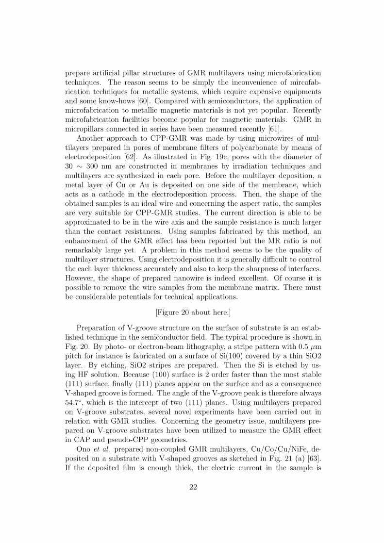
Preparation of V-groove structure on the surface of substrate is an estab-lished technique in the semiconductor field. The typical procedure is shown inFig. 20. By photo- or electron-beam lithography, a stripe pattern with 0.5 µmpitch for instance is fabricated on a surface of Si(100) covered by a thin SiO2layer. By etching, SiO2 stripes are prepared. Then the Si is etched by us-ing HF solution. Because (100) surface is 2 order faster than the most stable(111) surface, finally (111) planes appear on the surface and as a consequenceV-shaped groove is formed. The angle of the V-groove peak is therefore always54.7, which is the intercept of two (111) planes. Using multilayers preparedon V-groove substrates, several novel experiments have been carried out inrelation with GMR studies. Concerning the geometry issue, multilayers pre-pared on V-groove substrates have been utilized to measure the GMR effectin CAP and pseudo-CPP geometries.
Ono et al. prepared non-coupled GMR multilayers, Cu/Co/Cu/NiFe, de-posited on a substrate with V-shaped grooves as sketched in Fig. 21 (a) [63].If the deposited film is enough thick, the electric current in the sample is
22
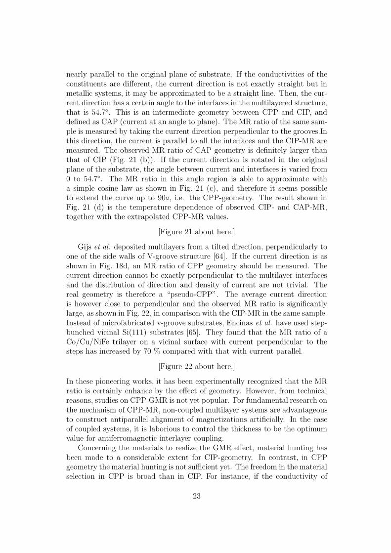
nearly parallel to the original plane of substrate. If the conductivities of theconstituents are different, the current direction is not exactly straight but inmetallic systems, it may be approximated to be a straight line. Then, the cur-rent direction has a certain angle to the interfaces in the multilayered structure,that is 54.7. This is an intermediate geometry between CPP and CIP, anddefined as CAP (current at an angle to plane). The MR ratio of the same sam-ple is measured by taking the current direction perpendicular to the grooves.Inthis direction, the current is parallel to all the interfaces and the CIP-MR aremeasured. The observed MR ratio of CAP geometry is definitely larger thanthat of CIP (Fig. 21 (b)). If the current direction is rotated in the originalplane of the substrate, the angle between current and interfaces is varied from0 to 54.7. The MR ratio in this angle region is able to approximate witha simple cosine law as shown in Fig. 21 (c), and therefore it seems possibleto extend the curve up to 90, i.e. the CPP-geometry. The result shown inFig. 21 (d) is the temperature dependence of observed CIP- and CAP-MR,together with the extrapolated CPP-MR values.
[Figure 21 about here.]
Gijs et al. deposited multilayers from a tilted direction, perpendicularly toone of the side walls of V-groove structure [64]. If the current direction is asshown in Fig. 18d, an MR ratio of CPP geometry should be measured. Thecurrent direction cannot be exactly perpendicular to the multilayer interfacesand the distribution of direction and density of current are not trivial. Thereal geometry is therefore a “pseudo-CPP”. The average current directionis however close to perpendicular and the observed MR ratio is significantlylarge, as shown in Fig. 22, in comparison with the CIP-MR in the same sample.Instead of microfabricated v-groove substrates, Encinas et al. have used step-bunched vicinal Si(111) substrates [65]. They found that the MR ratio of aCo/Cu/NiFe trilayer on a vicinal surface with current perpendicular to thesteps has increased by 70 % compared with that with current parallel.
[Figure 22 about here.]
In these pioneering works, it has been experimentally recognized that the MRratio is certainly enhance by the effect of geometry. However, from technicalreasons, studies on CPP-GMR is not yet popular. For fundamental research onthe mechanism of CPP-MR, non-coupled multilayer systems are advantageousto construct antiparallel alignment of magnetizations artificially. In the caseof coupled systems, it is laborious to control the thickness to be the optimumvalue for antiferromagnetic interlayer coupling.
Concerning the materials to realize the GMR effect, material hunting hasbeen made to a considerable extent for CIP-geometry. In contrast, in CPPgeometry the material hunting is not sufficient yet. The freedom in the materialselection in CPP is broad than in CIP. For instance, if the conductivity of
23
non-magnetic spacer layer is insulating, the current will flow only in magneticmetallic layers and eventually no GMR effect appears. In CPP geometry, onthe other hand, the spacer layer can be semiconductive or even insulating. Ifthe spacer layer is an insulator, tunneling GMR is expectable. MR only occursin CPP geometry and thus TMR is a kind of CPP-MR. In several experiments,metallic GMR system is combined with semiconductors such as Si, and GMRof hot electrons is observed [66,67]. The reason of large MR ratios observed inthose experiments is at least practically the CPP geometry.
3.5 Studies on nanomagnetic systems using GMR effect
Several experiments on magnetic nanowires are described in this section. Inan ultrathin wire of a ferromagnetic material, the direction of magnetizationslimited to be parallel to the wire axis because of the shape anisotropy. Asillustrated in Fig. 23, if there exists only one domain wall in a wire, the mag-netization reversal of the wire takes place associating with the propagationof the domain wall. The concept of domain wall has been established longtime ago but the dynamical behaviors of domain walls are still a crucial issuefrom technical aspects. From fundamental viewpoints, magnetic domain wallsin mesoscopic scales have attracted renewed attention since the possibility ofmacroscopic tunneling (MQT) process was predicted. Pioneering studies onMQT in mesoscopic systems have been reported by several groups [68]. If thewire cross section is small, the domain wall size should be small and then thedomain wall is expected to behave as a quasiparticle. Magnetization rever-sal phenomena in a nanoscale ferromagnetic wire are therefore of particularinterest but to observe a magnetization change in a single nanowire sampleis a hard experiment. Measurements of resistivity in wire samples are rathereasy but information on magnetism is normally not furnished. A domain wallmeans a region with a non-collinear spin arrangement and it should contributeto the resistivity. There have been several experiments to make clear a resis-tance due to the disordered spin structure but even concerning the sign of theresistance the results are not consistent. Some insists a decrease of resistancedue to domain wall and others an increase [69]. In any case, a contributionof domain wall to the resistivity is fairly small and is a minor effect comparedto the AMR effect. The resistance will be invariant during the magnetizationreversal as shown in Fig. 24 and therefore resistivity measurements seem to beuseless for the study of magnetization reversal process in nanowires.
By utilizing GMR effect, however, resistivity measurements become a sen-sitive tool to observe magnetization reversal phenomena. If we prepare a wiresample consisting of trilayer exhibiting non-coupled type GMR, the resistivityshows the ratio of antiparallel alignment of magnetizations. As illustrated inFig. 23 (a), if the magnetization is reversed by the propagation of a singledomain wall, the degree of reversal is observed as a change of resistance. An
24
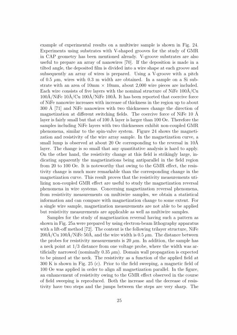
example of experimental results on a multiwire sample is shown in Fig. 24.Experiments using substrates with V-shaped grooves for the study of GMRin CAP geometry has been mentioned already. V-groove substrates are alsouseful to prepare an array of nanowires [70]. If the deposition is made in atilted angle, the deposited film is divided into a wire shape at each groove andsubsequently an array of wires is prepared. Using a V-groove with a pitchof 0.5 µm, wires with 0.3 m width are obtained. In a sample on a Si sub-strate with an area of 10mm × 10mm, about 2,000 wire pieces are included.Each wire consists of five layers with the nominal structure of NiFe 100A/Cu100A/NiFe 10A/Cu 100A/NiFe 100A. It has been reported that coercive forceof NiFe nanowire increases with increase of thickness in the region up to about300 A [71] and NiFe nanowires with two thicknesses change the direction ofmagnetization at different switching fields. The coercive force of NiFe 10 Alayer is fairly small but that of 100 A layer is larger than 100 Oe. Therefore thesamples including NiFe layers with two thicknesses exhibit non-coupled GMRphenomena, similar to the spin-valve system. Figure 24 shows the magneti-zation and resistivity of the wire array sample. In the magnetization curve, asmall lump is observed at about 20 Oe corresponding to the reversal in 10Alayer. The change is so small that any quantitative analysis is hard to apply.On the other hand, the resistivity change at this field is strikingly large, in-dicating apparently the magnetizations being antiparallel in the field regionfrom 20 to 100 Oe. It is noteworthy that owing to the GMR effect, the resis-tivity change is much more remarkable than the corresponding change in themagnetization curve. This result proves that the resistivity measurements uti-lizing non-coupled GMR effect are useful to study the magnetization reversalphenomena in wire systems. Concerning magnetization reversal phenomena,from resistivity measurements on multiwire samples, we obtain a statisticalinformation and can compare with magnetization change to some extent. Fora single wire sample, magnetization measurements are not able to be appliedbut resistivity measurements are applicable as well as multiwire samples.
Samples for the study of magnetization reversal having such a pattern asshown in Fig. 25a were prepared by using electron-beam lithography apparatuswith a lift-off method [72]. The content is the following trilayer structure, NiFe200A/Cu 100A/NiFe 50A, and the wire width is 0.5 µm. The distance betweenthe probes for resistivity measurements is 20 µm. In addition, the sample hasa neck point at 1/3 distance from one voltage probe, where the width was ar-tificially narrowed (nominally 0.35 µm). Domain wall propagation is expectedto be pinned at the neck. The resistivity as a function of the applied field at300 K is shown in Fig. 25 (c). Prior to the field sweeping, a magnetic field of100 Oe was applied in order to align all magnetization parallel. In the figure,an enhancement of resistivity owing to the GMR effect observed in the courseof field sweeping is reproduced. Both the increase and the decrease of resis-tivity have two steps and the jumps between the steps are very sharp. The
25
relative height ratio of the two steps is 1:2 at both cases, which means that1/3 of the magnetization is reversed first and after a while remaining 2/3 isreversed. As expected, a domain wall is trapped at the neck point and whenthe external field exceeds a certain critical value, the domain wall is depinnedor another domain wall comes from the other side to complete the magnetiza-tion reversal. For this single wire sample, magnetization measurements are notapplicable but from the resistivity measurements the process of magnetizationreversal is clearly checked. It is no doubt that the magnetic structure at eachstage is as illustrated in the figure.The result indicates that the resistivity iskept constant at each stage but the resistivity change at the transition betweenstages is very sudden. The process of magnetization reversal is therefore re-garded as a propagation of single domain wall and the velocity should be veryhigh.
The velocity of domain wall propagation is in principle able to estimatefrom the time dependence of resistivity. However, if the velocity is very fastand the probing length is too short, the variation of resistivity as a function oftime is not easy to measure. For the velocity measurements, a sample with 100times longer distance (2mm) was prepared with the structure of NiFe 400A/Cu200A/NiFe 50A and 0.5 µm width, having no neck point [73]. The resistivityas a function of external field at 77 K is shown in Fig. 26 (a). After applying500 Oe in the negative direction, the resistivity was monitored with sweepingthe field in the rate of 20 Oe/s. The resistivity enhancement due to the GMReffect is found in the region of 35 and 85 Oe and the increase and the decreasecorrespond to the reversal in 50 A and 400 A NiFe layers, respectively. Thetime dependence was measured for the sharp switching in the thicker layer byusing a digital oscilloscope. As shown in Fig. 26 (b), the change of resistivityhas taken place in the time interval of 11 µsec. Because the field sweeping rateis very slow, the external field during the time dependence measurement isactually constant, i.e., 88 Oe. The result indicates that the resistivity changeis almost linear to the time variation, which suggests that the magnetizationreversal is caused by a single domain wall moving with a constant velocity.Since the time length to travel in the distance of 2 mm is measured to be11 µsec, the velocity is calculated to be 182 m/s. The domain wall in a wire isregarded as quasiparticle moving in a very fast but almost constant velocity.The experiments introduced above prove that behaviors of a single domainwall are able to be monitored by the resistivity measurements utilizing theGMR principle. This method is useful for the study of magnetization reversalphenomena in mesoscopic systems and dynamical behaviors of domain walls.
In the initial stage of the experiment, the whole body of the wire sampleincluding the terminal parts has been composed of the same magnetic structurefor the convenience of the sample preparation and accordingly the observedswitching field values are considerably distributed. Possibly because of neckor elbow parts included in the sample, the structure of domain wall produced
26
at each run is not the same from a microscopic point of view. Improvementof the quality of wire samples has been made by preparing the terminal partsby a non-magnetic metal (Cu) and only the wire part was constructed bymagnetic layers [74]. In addition, as illustrated in Fig. 27 (b), a pad witha wide area was attached at one end of the wire to specify the nucleationsite and the direction of domain wall propagation. The results in Fig. 27were obtained for a sample whose magnetic layers are consisting of permalloyand cobalt. Similarly to the results in Fig. 25, abrupt changes of resistivitydue to the individual reversals of magnetization in permalloy and cobalt areobserved. For this sample, the values of external field for the reversal arereproducibly obtained. The reversal process is considered to be the following:The nucleation starts in the pad part under a rather low field but a domainwall is trapped at the shoulder and does not proceed into the wire part untilthe external field exceeds a certain critical field. This model is verified by themeasurements with changing the direction of external field relative to the wireaxis. With increase of the angle θ, from the axis, the switching field increasesas shown in Fig. 27. However, for the sample with a pad, H cos θ is found tobe constant. Namely the component of magnetic field to the direction of theaxis is the same. The domain wall starts to propagate when the magnetic fieldstrength to the propagation direction reaches to a critical value, Each resistivitymeasurement as a function of the angle shows very sharp changes suggestingall the process is due to a single domain wall propagation. The curvatureof resistivity at higher angles is attributed to the AMR effect and also thedeviation of the magnetization alignment from antiparallel caused by applyingan external field at an angle to the wire axis. The domain wall formation andmovement are thus satisfactorily controlled and this methodology seems tobe promising to study the magnetization reversal phenomena in samples withsmaller sizes.
[Figure 23 about here.]
[Figure 24 about here.]
[Figure 25 about here.]
[Figure 26 about here.]
[Figure 27 about here.]
3.6 Summary
Experimental studies on GMR and related phenomena have been surveyedbriefly. The discovery of GMR revealed us that the influence of magnetism,or spin polarization, on transport properties is significant. Investigations are
27
being made extensively for various types of magnetoresistance phenomena withhoping to explore novel phenomena caused as an interplay between magnetismand transport. An important key word for further progress seems to be micro-or nanofabrication. A newer MR effect will appear on the stage where thesample structure is controlled on an atomic scale. It is less than 10 years fromthe discovery of GMR to the commercial application as the GMR head, whichis surprisingly short. This fact evidences that this field has a very high activityand in this field the distance between basic physics and application is rathersmall. At the moment, the spin-valve system is used as the GMR head and thespecific properties satisfy to cover the density of recording up to several tensMbit/in2. However, some years later, read out sensors with higher sensitivitywill be required. In future also, the studies on magnetoresistance propertiesshould be of great importance both from basic and technical viewpoints. Inthis article, only a limited number of publications were introduced. This field israpidly expanding and it is practically impossible to cover all the publicationsin a small volume. The author apologizes that many updated and distinguishedworks could not be cited here.
The author thanks to the collaborators, whose names are shown as thecoauthors of the publications in the reference list. The works of the authorwere supported by Grants-in-Aid from Monbusho and NEDO.
28

References
[1] M. N. Baibich, J. M. Broto, A. Fert, F. Nguyen Van Dau, P. Etienne, G.Creuzet, A. Friederich and J. Chazelas, Phys. Rev. Lett. 61 (1988) 2472.
[2] M. Julliere, Phys. Lett. 54 (1975) 225.
[3] S. Maekawa and U. Gafvert, IEEE Trans. Mag. 18 (1982) 707.
[4] E. Velu, C. Dupas, D. Renard, J. P. Renard and J. Seiden, Phys. Rev. B37 (1988) 668.
[5] P. Grunberg, R. Schreiber, Y. Pang, M. B. Brodsky and H. Sowers,Phys. Rev. Lett. 57 (1986) 2442. F. Saurenbach, U. Walz, L. Hinchey,P. Grunberg and W. Zinn, J. Appl. Phys. 62 (1988) 3473.
[6] G. Binasch, P. Grunberg, F. Saurenbach and W. Zinn, Phys. Rev. B 39(1989) 4828. M. Vohl, J. Barnas and P. Grunberg, Phys. Rev. B 36 (1989)12003.
[7] C. Carbone and S. F. Alvarado, Phys. Rev. B 39 (1987) 2433. S. F.Alvarado and C. Carbone, Physica B 149 (1988) 43.
[8] For magnetic multilayer studies before GMR, see references cited inMetal-lic Superlattices, edited by T. Shinjo and T. Takada (Elsevier Sci. Pub.,1987).
[9] A. Cebollada, J. L. Martinez, J. M. Gallego, J. J. de Miguel, R. Miranda,S. Ferre, F. Batallan, G. Fillion and J. P. Rebouillat, Phys. Rev. B 39(1989) 9726.
[10] N. Hosoito, S. Araki, K. Mibu and T. Shinjo, J. Phys. Soc. Jpn. 59 (1990)1925.
[11] R. Schad, C. D. Potter, P. Belien, G. Verbanck, J. Dekoster, G. Lan-gouche, V. V. Moshchalkov and Y. Bruynseraede, J. Magn. Magn. Mater.148 (1995) 331.
[12] A review paper for theories on GMR for instance is: P. M. Levy, SolidState Phys. 47 (1994) 367. Experimental results on GMR are compre-hensively listed in the following, A. Berthelemy, A. Fert and F. Petroff,Handbook of Magnetic Materials, vol. 12, edited by K. H. J. Bushow (El-sevier, 1999) p. 1.
[13] D. H. Mosca, F. Petroff, A. Fert, P. A. Schroeder, W. P. Pratt Jr. and R.Loloee, J. Magn. Magn. Mater. 94 (1991) 1.
29
[14] S. S. P. Parkin, R. Bhadra and K. P. Roche, Phys. Rev. Lett. 66 (1991)2152.
[15] S. S. P. Parkin, N. More and K. P. Roche, Phys. Rev. Lett. 64 (1990)2304.
[16] S. S. P. Parkin, Phys. Rev. Lett. 67 (1991) 3598.
[17] J. Unguris, R. J. Celotta and D. T. Pierce, Phys. Rev. Lett. 67 (1991)140. D. T. Pierce, R. J. Celotta and J. Unguris, J. Appl. Phys. 73 (1993)6201.
[18] P. J. H. Bloemen, M. T. Johnson, M. T. H. van der Vorst, R. Coehoorn,J. J. de Vries, R. Jungblut, J. an de Stegg, A. Reinders and W. J. M. deJonge, Phys. Rev. Lett. 72 (1994) 764.
[19] A. Fert, P. Grunberg, A. Barthelemy, F. Petroff and W. Zinn, J. Magn.Magn,Mater. 140-1 (1995) 1.
[20] Review papers on interlayer couplings for instance are: B. Heinrich andJ. A. C. Bland, Ultrathin Magnetic Films II, (Spring-Verlag, 1994). P.Grunberg, Handbook of Magnetic materials, vol.12, edited by K.H.J.Buschow (Elsevier, 1999) p.1.
[21] F. E. Fullerton, S. D. Bader and J. L. Robertson, Phys. Rev. Lett. 77(1996) 1382.
[22] A. Schreyer, J. F. Ankner, T. Zeidler, H. Zabel, M. Schafer. J. A. Wolf,P. Grunberg and C. F. Majkrzak, Phys. Rev. B 52 (1995) 16066.
[23] K. Mibu, M. Almokhtar, S. Tanaka, A. Nakanishi, T. Kobayashi and T.Shinjo, Phys. Rev. Lett. 84 (2000) 2243.
[24] D. T. Pierce, J. Unguris, R. J. Celotta and M. D. Stiles; J. Magn. Magn.Mater. 200 (1999) 290.
[25] T. Shinjo and H. Yamamoto, J. Phys. Soc. Jpn. 59 (1990) 3061.
[26] K. Shigeto, T. Shinjo and T. Ono, Appl. Phys. Lett. 75 (1999) 2815.
[27] N. Hosoito, T. Ono, H. Yamamoto, T. Shinjo and Y. Endoh, J. Phys. Soc.Jpn. 64 (1995) 581.
[28] B. Dieny, V. S. Speriosu, S. S. P. Parkin, B. A. Gurney, D. R. Wilhoitand D. Mauri, Phys. Rev. B 43 (1991) 1297.
[29] H. Yamamoto, T. Okuyama, H. Dohnomae and T. Shinjo, J. Magn. Magn.Mater. 99 (1991) 243.
30
[30] T. Okuyama, H. Yamamoto and T. Shinjo, J. Magn. Magn. Mater. 113(1992) 79.
[31] T. Shinjo, Magnetism and Structure in Systems of Reduced Dimension,edited by R. F. C. Farrow et al., (Plenum Press, 1995) p. 323.
[32] H. Yamamoto, Y. Motomura, T. Anno and T. Shinjo, J. Magn. Magn.Mater. 126 (1993) 437.
[33] H.Itoh, J.Inoue, and S.Maekawa, J. Magn. Magn. Mater. 126 (1993) 479.
[34] J. Mathon, Phys. Rev. B 54 (1996), Phys. Rev. B 55 (1997) 960.
[35] H. Sato, Y. Aoki, Y. Kobayashi, H. Yamamoto and T. Shinjo, J. Phys.Soc. Jpn. 62 (1993) 431.
[36] J. Sakurai, M. Horie, S. Araki, H. Yamamoto and T. Shinjo, J. Phys. Soc.Jpn. 60 (1991) 2522.
[37] J. Shi, R.C. Yu, S.S.P. Parkin and M.B. Salamon, J. Appl. Phys. 73(1993) 5524.
[38] K. Nishimura, J. Sakurai, K. Hasegawa, Y. Saito, K. Inomata andT. Shinjo, J. Phys. Soc. Jpn. 63 (1994) 2685.
[39] E.Yu.Tsymbal, D.G.Pettifor, J.Shi, M.B.Salamon, Phys. Rev. B 59 (1999)8371.
[40] W. F. Egelhoff Jr., P. J. Chen, C. J. Powell, M. D. Stiles, R. D. McMichael,C. -L. Lin, J. M. Sivertsen J. H. July, K. Takano, A. E. Berkowitz, T. C.Anthony and J. A. Brug, J. Appl. Phys. 82 (1997) 6142.
[41] For example, Y. Sugita, Y. Kawawake, M. Satomi and H. Sakakima, Jpn.J. Appl. Phys. 37 (1998) 5984.
[42] I. Nakatani, Materia 35 (1996) 854 (In Japanese).
[43] A. E. Berkowits, J. R. Mitchell, M. J. Carey, A. P. Young, S. Zhang, F.E. Spada, F. T. Parker, A. Hutten and G. Thomas, Phys. Rev. Lett. 68(1992) 3745.
[44] J. Q. Xiao, J. S. Jiang and C. L. Chien. Phys. Rev. Lett. 68 (1992) 3749.
[45] S. A. Makhlouf, K. Sumiyama, K. Wakoh, K. Suzuki, K. Takanashi andH. Fujimori, J. Magn. Magn. Mater. 126 (1993) 485.
[46] Ch. Somsen, M. Acet, G. Nepecks and E. F. Wassermann, J. Magn. Magn.Mater. 208 (2000) 191.
31
[47] T. Miyazaki and N. Tezuka, J. Magn. Magn. Mater. 139 (1995) L231.T. Miyazaki, N. Tezuka, S. Kumagai, Y. Ando, H. Kubota, J. Murai, T.Watabe and M. Yokota, J. Phys. D: Appl. Phys. 31 (19998) 630.
[48] J. S. Moodera, L. R. Kinder, T. M. Wong and R. Meservey, Phys. Rev.lett. 74 (1995) 3273.
[49] S. S. P. Parkin, this volume.
[50] S. Mitani, H. Fujimori and S. Ohnuma, J. Magn. Magn. Mater. 165 (1997)141.
[51] L. Jirman, V. Sechovsky, L. Havela, W. Ye, T. Takabatake, H. Fujii, T.Suzuki, T. Fujita, E. Bruck and F. R. De Boer, J. Magn. Magn. Mater.104-107 (1992) 19.
[52] A. Urushibara, Y. Morimoto, T. Arima, A. Asamitsu, G. Kido and Y.Tokura, Phys. Rev. B 51 (1995) 14103.
[53] Y. Tokura,
[54] S. Maekawa, J. Inoue and H. Itoh, J. Appl. Phys. 79 (1996) 4730.
[55] K. Takanashi, S. Mitani, K. Himi and H. Fujimori, Appl. Phys. Lett. 72(1998) 737.
[56] M. A. M. Gijs and G. E. W. Bauer, Adv. Phys. 46 (1997) 285.
[57] W. P. Pratt Jr., S.-F. Lee, J. M. Slaughter, R. Loloee, P. A. Schroederand J. Bass, Phys. Rev. Lett. 66 (1991) 3060.
[58] M. A. M. Gijs, S. K. J. Lenczowski and J. B. Giesbers, Phys. Rev. Lett.70 (1993) 3343.
[59] M. A. M. Gijs, J. B. Giesbers, S. K. J. Lenczowski and H. H. J. M. Janssen,Appl. Phys. Lett. 63 (1993) 111.
[60] I. Nakatani,
[61] M.C. Cyrille, S. Kim, M.E. Gomez, J. Santamaria, K.M. Krishnan, andI.K. Schuller, Pys. Rev. B 62 (2000) 3361.
[62] L. Piraux, J. M. George, J. F. Despres, C. Leroy, E. Ferain, R. Legras,K. Ounadjela and A. Fert, Appl. Phys. Lett. 65 (1994) 2484. A.Fert andL.Piraux, J.Magn. Magn. Mater. 200 (1999) 338.
[63] T. Ono and T. Shinjo, J. Phys. Soc. Jpn. 64 (1995) 363. T. Ono, Y.Sugita, K. Shigeto, K. Mibu, N. Hosoito and T. Shinjo, Phys. Rev. B 55(1997) 14457.
32
[64] M. A. M. Gijs, M. T. Johnson, A. Reinders, P. E. Huisman, R. J. M. vander Veerdonk, S. K. J. Lenczowski and R. M. J. van Gansewinkel, Appl.Phys. Lett. 66 (1995) 1839.
[65] P. S. Anil Kumar, R. Jansen, O. M. J. van’t Erve, R. Vlutters, P. de Haanand J. C. Lodder, J. Magn. Magn. Mater. 214 (2000) L1.
[66] K. Mizushima, T. Kinno, K. Tanabe and T. Yamauchi, Phys. Rev. B 58(1998) 4660.
[67] A text book for MQT phenomena is for instance: E. M. Chudnovskyand J. Tejada, Macroscopic Quantum Tunneling of the Magnetic Moment(Cambridge Univ. Press. 1998). References are cited therein.
[68] Examples of recent experimental papers on the resistance of domain wallsare; J. F. Gregg, W. Allen, K. Ounadjela, M. Viret, M. Hehn, S. M.Thompson and J. M. D. Coey, Phys. Rev. Lett. 77 (1996) 1580. K. Hongand N. Giordano, Condens. Matter. 10 (1998) L401. Y. Otani, S. G. Kim,K. Fukamichi, O. Kitakami and Y. Shimada, IEEE Trans. Mag. 34 (1998)1096. K. Mibu, T. Nagahama and T. Shinjo, Phys. Rev. B 58 (1998) 6442.U. Ruediger, J. Yu, S. Zhang, A. D. Kent and S. S. P. Parkin, Phys. Rev.Lett. 80 (1998) 5639. Theoretical papers are; P. M. Levy and S. Zhang,Phys. Rev. Lett. 79 (1997) 5110. G. Tatara and H. Fukuyama, Phys. Rev.Lett. 78 (1998) 3773.
[69] T. Ono, Y. Sugita and T. Shinjo, J. Phys. Soc. Jpn. 65 (1996) 3021.
[70] Y. Sugita, T. Ono and T. Shinjo (unpublished).
[71] T. Ono, H. Miyajima, K. Shigeto ad T. Shinjo, Appl. Phys. Lett. 72(1998) 1116.
[72] T. Ono, H. Miyajima, K. Shigeto, K. Mibu, N. Hosoito and T. Shinjo, J.Appl. Phys. 85 (1999) 6181.
[73] K. Shigeto, T. Okuno, T. Shinjo, Y. Suzuki and T. Ono, to be publishedin J. Appl. Phys.
33
List of Figures
1 (a) Anisotropic magnetoresistance (AMR). V , I , M , H and θare voltage, current, magnetization, external field and the anglebetween the current and the magnetization, respectively. (b)Application of AMR sensor. . . . . . . . . . . . . . . . . . . . . 37
2 Resistivity of Fe/Cr multilayers at 4.2 K as a function of mag-netic field. Magnetization curves at 4.2 K are shown in theinserted figure. The numbers represent the Cr layer thicknesses. 38
3 Resistivity vs. temperature of pure Ni metal. Tc indicates theCurie temperature. The dotted curve is an extension of theresistivity curve in the paramagnetic region to the ferromagneticregion for comparison. . . . . . . . . . . . . . . . . . . . . . . . 39
4 (a) Time of flight polarized neutron diffraction profiles for the1/2-order peak from a multilayer, [Fe 2A/Cr 12A]×30 at 300 K[10]. The 1st order peak is also observed. The relative inten-sities of 1st and 1/2-order peaks are not proportional to thestructure factors because of the wavelength dependence of theincident neutron beam intensity. External field dependence ofmagnetization, resistivity, and the 1/2-order neutron diffractionpeak intensity at 300 K of a multilayer [Fe 27A/Cr 12A]×30 isshown as Fig. 4 (b), (c) and (d), respectively. . . . . . . . . . . 40
5 MR ratio of Cu/Co multilayers as a function of Cu layer thick-ness. . . . . . . . . . . . . . . . . . . . . . . . . . . . . . . . . 41
6 (a) simple wedge (b) double wedges . . . . . . . . . . . . . . . 427 Magnetization (a) and resistivity (b) of [NiFe 30A/Cu 50A/Co
30A/Cu 50A]×15 at 80 K and 300 K. . . . . . . . . . . . . . . 438 Non-coupled type GMR ratio in [NiFe 25A/Cu 55A/Co 25A/Cu
55A]×15 as a function of the angle between the magnetic fieldand the electric current. . . . . . . . . . . . . . . . . . . . . . . 44
9 MR effect of [Cu(d)/Co 25A/Cu(d)/NiFe 25A]×15 at 300 Kunder a rotating field of 20 Oe. The angle θ means the directionof the external field. (a) d=100 A, (b) d = 55 A. . . . . . . . . 45
10 Comparison of the non-coupled type GMR effect in Cu-, Au-and Ag-based films. The thicknesses of magnetic layers (NiFeand Co) are 25 A. The number of multilayer repetition is 5, forall samples. . . . . . . . . . . . . . . . . . . . . . . . . . . . . . 46
11 MR and magnetization of multilayers, with and without theinterface doping by 0.5 A Cr layer. . . . . . . . . . . . . . . . . 47
12 Influence of interface doping with 3d element on MR. . . . . . . 48
34
13 (Upper) Field dependence of MR ratio at 295 K, 78 K and4.2 K. (Middle) Thermal conductivity vs. magnetic field for[NiFe 20A/Cu 40A/Co 20A/Cu 40A]×50 DT means the tem-perature change caused by the field sweeping, which correspondsto the thermal conductivity. ∆T is the initial temperature dif-ference at 3 kOe. (Lower) Schematic illustration of the structureof the sample holder. . . . . . . . . . . . . . . . . . . . . . . . 49
14 Thermopower at 80 K of Cu/Co/Cu/NiFe as a function of mag-netic field. . . . . . . . . . . . . . . . . . . . . . . . . . . . . . 50
15 Schematic illustration of spin-valve structures. (a) Initial, and(b) Sophisticated. . . . . . . . . . . . . . . . . . . . . . . . . . 51
16 Magnetization and resistivity at 4.2 K of a granular system(Fe/Ag films) under very high fields. . . . . . . . . . . . . . . . 52
17 CIP, CPP, and CAP geometries. . . . . . . . . . . . . . . . . . 5318 Various sample structures for the CPP-MR studies. . . . . . . 5419 Temperature dependence of the CPP-MR of Co/Cu pillar struc-
ture. . . . . . . . . . . . . . . . . . . . . . . . . . . . . . . . . . 5520 Procedure for preparing a substrate having a surface with V-
groove microstructure. . . . . . . . . . . . . . . . . . . . . . . . 5621 (a) Schematic illustration of the multilayer sample structure for
CAP-MR studies. (b) MR ratios at 5 K for the same samplesin CAP and CIP geometries. (c) CAP-MR ratio as a functionof the angle φ. The definition of φ is given in Fig. 21 (a). . . . 57
22 Temperature dependence of pseudo CPP-MR and CIP-MR ra-tios for a multilayer [Co15A/Cu60A]×32. (Refer Fig. 19 (d) forthe sample structure.) . . . . . . . . . . . . . . . . . . . . . . . 58
23 (a) and (b) Magnetization reversal of a wire associating withthe propagation of the domain wall. (c) Structure of trilayersystem. (d) Resistance change associating with magnetizationreversal. . . . . . . . . . . . . . . . . . . . . . . . . . . . . . . . 59
24 (a) Structure of wire array deposited on a V-groove substrate.The arrow indicates the direction of the deposition. (b) Magne-tization and (c) resistivity at 300 K of wire arrays with a nomi-nal structure of [NiFe 100A/Cu 100A/NiFe 10A/Cu 100A/NiFe100A] as a function of external field. . . . . . . . . . . . . . . . 60
25 (a) Schematic illustration of the sample and (b) SEM image.The sample consists of a NiFe(200A)/Cu(100A)/NiFe(50A) tri-layer. (c) Resistance as a function of the external magneticfield at 300 K determined by the four-point dc technique. (d)Schematic diagram of the magnetic domain structures. . . . . . 61
26 (a) Resistance as a function of the external magnetic field at77 K. (b) Time variation of the resistance during the magneti-zation reversal of the 400 A NiFe layer. . . . . . . . . . . . . . 62
35
27 Schematic illustrations of the top views of the two types of wireswith and . Resistance as a function of the external magnetic fieldH parallel to the wire axis at 300 K. Angular dependence of theswitching field Hsw of the Co layer at 300 K. The magnetic fieldwas applied in the plane of the substrate at an angle θ withrespect to the wire axis. . . . . . . . . . . . . . . . . . . . . . . 63
36
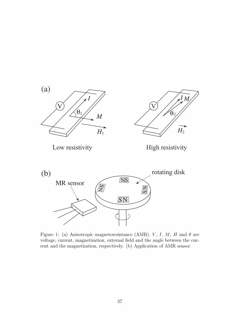
V
(a)
(b)
Low resistivity
I
M
H
θ
1
V
High resistivity
I M
H
θ
2
1 2
S
N
MR sensor
rotating disk
S
S
N
NN
S
Figure 1: (a) Anisotropic magnetoresistance (AMR). V , I , M , H and θ arevoltage, current, magnetization, external field and the angle between the cur-rent and the magnetization, respectively. (b) Application of AMR sensor.
37
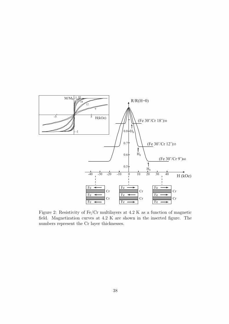
H(kOe)
H (kOe)
(Fe 30¯/Cr 18¯)30
(Fe 30¯/Cr 12¯)35
(Fe 30¯/Cr 9¯)60
Fe
Fe
Fe
Cr
Cr
Fe
Fe
Fe
Cr
Cr
Fe
Fe
Fe
Cr
Cr
R/R(H=0)
-40 -30 -20 -10 0 10 20 30 40
0.5
0.6
0.7
0.8
Hs
Hs
Hs-1
1-
-
-5 5
- -
M/Ms 60
1812
9
30
Figure 2: Resistivity of Fe/Cr multilayers at 4.2 K as a function of magneticfield. Magnetization curves at 4.2 K are shown in the inserted figure. Thenumbers represent the Cr layer thicknesses.
38
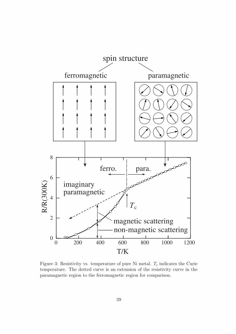
spin structure
ferromagnetic paramagnetic
Tc
ferro. para.
imaginaryparamagnetic
magnetic scatteringnon-magnetic scattering
0 200 400 600 800 1000 1200
T/K
0
2
4
6
8
R/R
(300
K)
Figure 3: Resistivity vs. temperature of pure Ni metal. Tc indicates the Curietemperature. The dotted curve is an extension of the resistivity curve in theparamagnetic region to the ferromagnetic region for comparison.
39
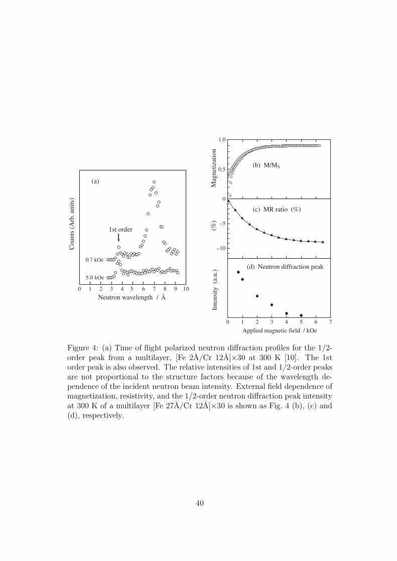
Cou
nts
(Arb
. uni
ts)
1st order
0.7 kOe
5.0 kOe
(a)
0 1 2 3 4 5 6 7 8 9 10
Neutron wavelength / Å
0.5
1.0
Mag
netiz
atio
n
(b) M/MS
–10
–5
0
(%)
(c) MR ratio (%)
0 1 2 3 4 5 6 7
Applied magnetic field / kOe
Inte
nsity
(a.
u.) (d) Neutron diffraction peak
Figure 4: (a) Time of flight polarized neutron diffraction profiles for the 1/2-order peak from a multilayer, [Fe 2A/Cr 12A]×30 at 300 K [10]. The 1storder peak is also observed. The relative intensities of 1st and 1/2-order peaksare not proportional to the structure factors because of the wavelength de-pendence of the incident neutron beam intensity. External field dependence ofmagnetization, resistivity, and the 1/2-order neutron diffraction peak intensityat 300 K of a multilayer [Fe 27A/Cr 12A]×30 is shown as Fig. 4 (b), (c) and(d), respectively.
40
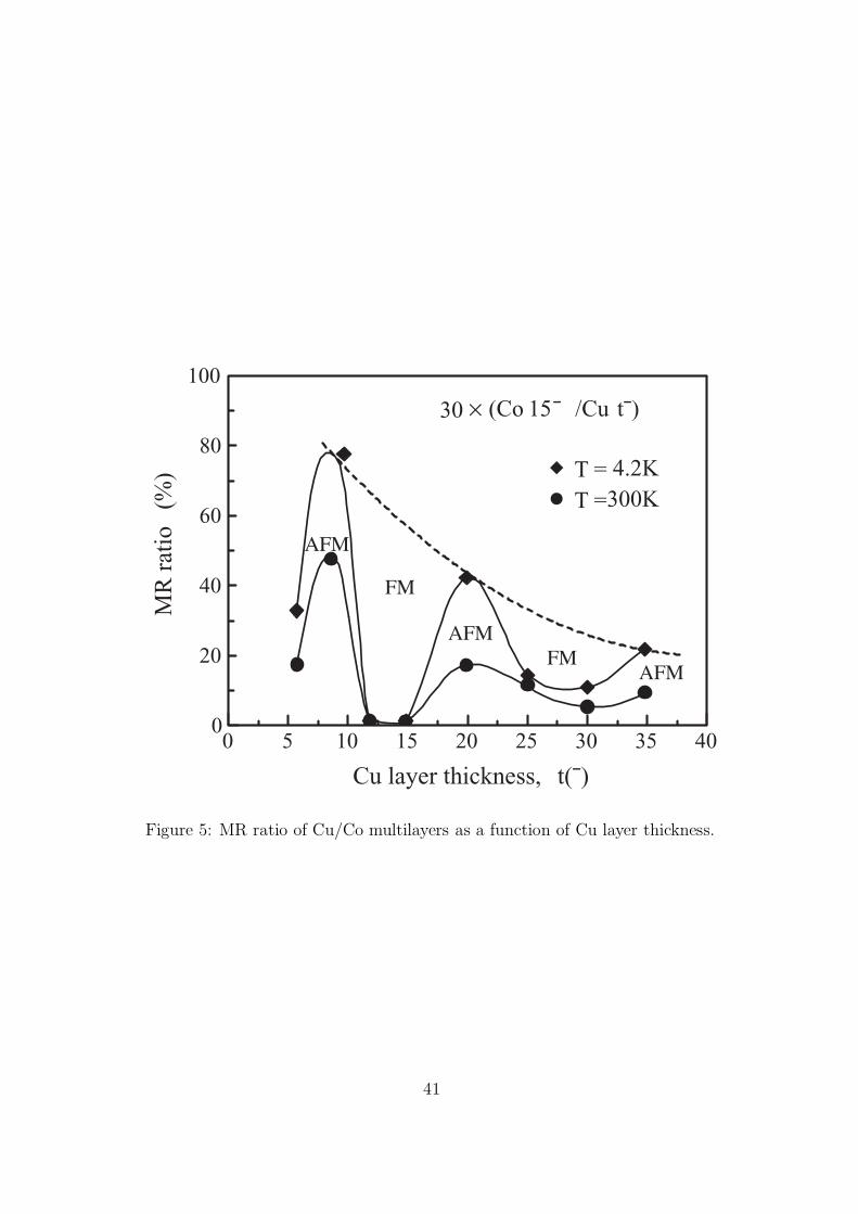
0 5 10 15 20 25 30 35 40
Cu layer thickness, t(¯)
0
20
40
60
80
100
MR
rat
io
(%)
AFM
FM
30 × (Co 15¯ /Cu t¯)
T = 4.2KT =300K
FMAFM
AFM
Figure 5: MR ratio of Cu/Co multilayers as a function of Cu layer thickness.
41
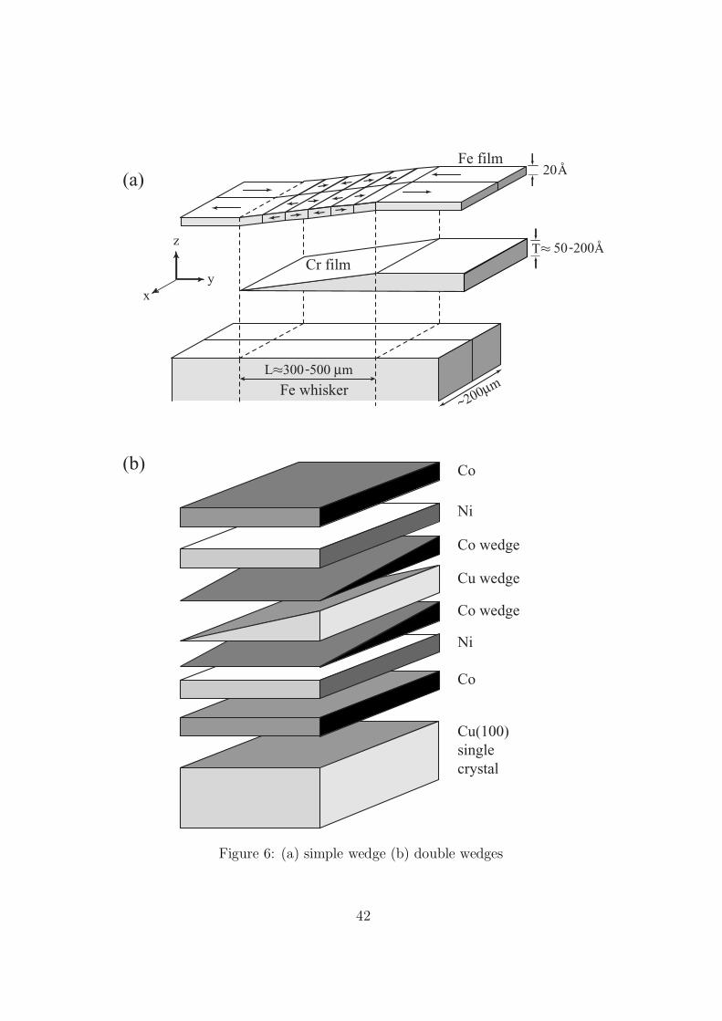
Co
Ni
Co
Ni
Co wedge
Co wedge
Cu wedge
Cu(100)singlecrystal
Fe whisker
Cr film
L 300 -500 µmoo
z
yx
Fe film20
50 -200
~200µm
(a)
(b)
Å
Å
T oo
Figure 6: (a) simple wedge (b) double wedges
42
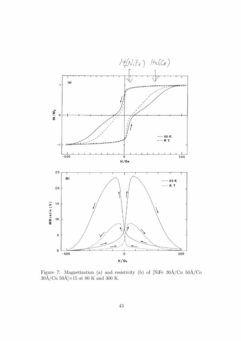
Figure 7: Magnetization (a) and resistivity (b) of [NiFe 30A/Cu 50A/Co30A/Cu 50A]×15 at 80 K and 300 K.
43
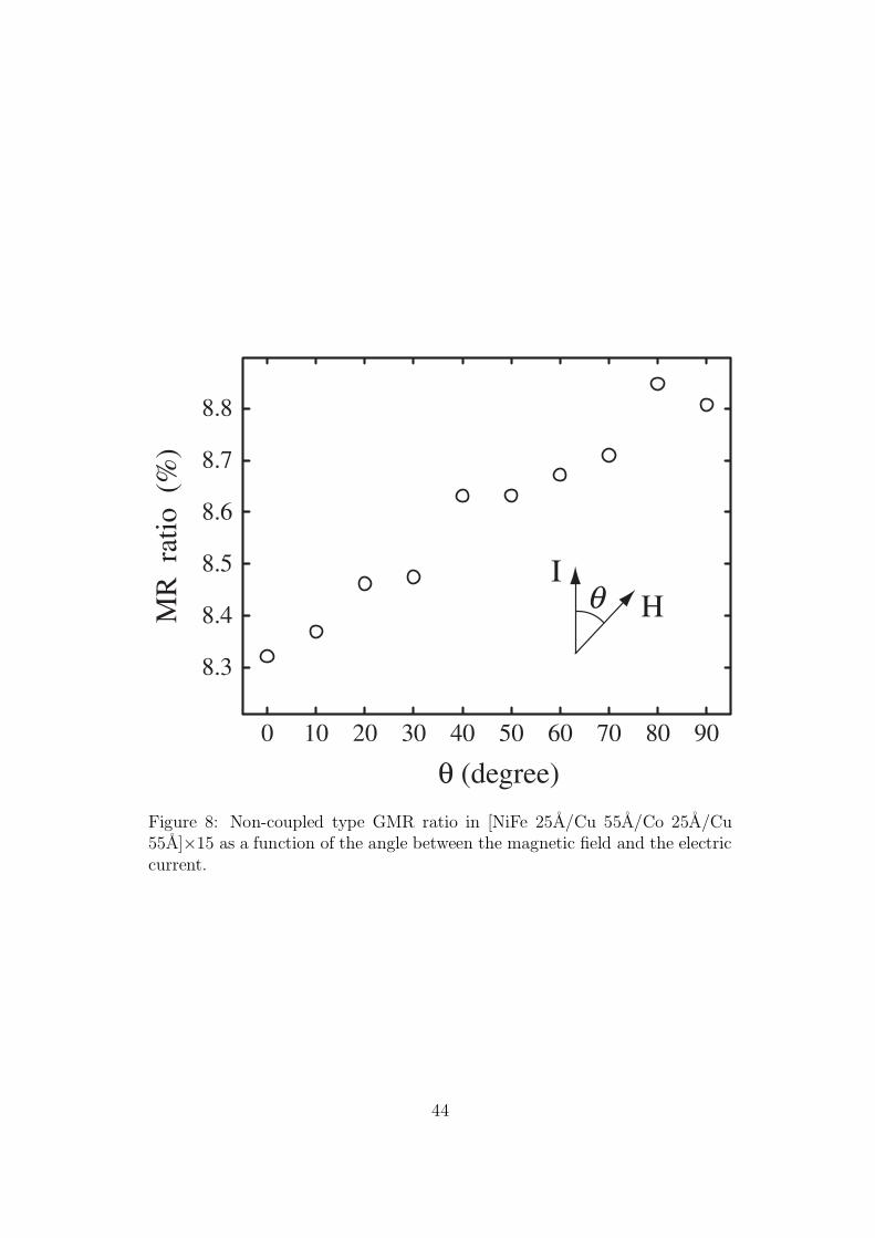
0 10 20 30 40 50 60 70 80 90
θ (degree)
8.3
8.4
8.5
8.6
8.7
8.8
MR
rat
io (
%)
IHθ
Figure 8: Non-coupled type GMR ratio in [NiFe 25A/Cu 55A/Co 25A/Cu55A]×15 as a function of the angle between the magnetic field and the electriccurrent.
44
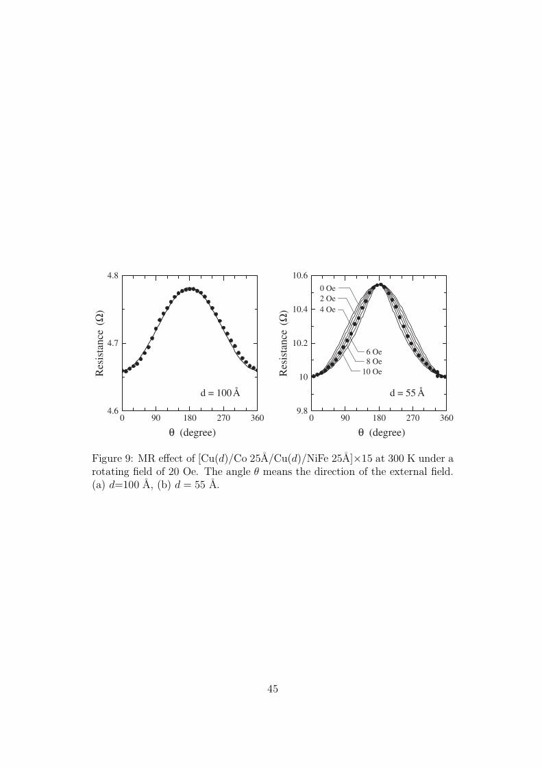
0 90 180 270 360
θ (degree)
9.8
10
10.2
10.4
10.6
d = 55 Å
0 90 180 270 360
θ (degree)
4.6
4.7
4.8
Res
ista
nce
(Ω)
Res
ista
nce
(Ω)
d = 100Å
8 Oe6 Oe
10 Oe
0 Oe
4 Oe2 Oe
Figure 9: MR effect of [Cu(d)/Co 25A/Cu(d)/NiFe 25A]×15 at 300 K under arotating field of 20 Oe. The angle θ means the direction of the external field.(a) d=100 A, (b) d = 55 A.
45
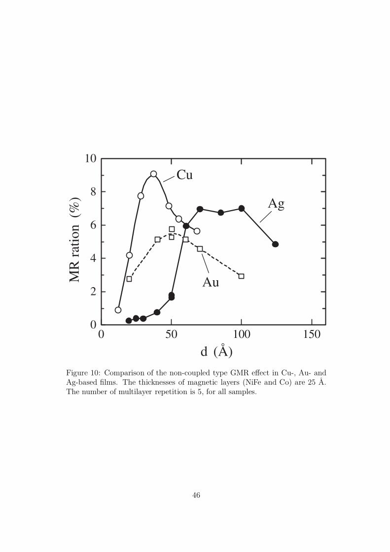
0 50 100 150
d (Å)
0
2
4
6
8
10
MR
rat
ion
(%) Ag
Au
Cu
Figure 10: Comparison of the non-coupled type GMR effect in Cu-, Au- andAg-based films. The thicknesses of magnetic layers (NiFe and Co) are 25 A.The number of multilayer repetition is 5, for all samples.
46
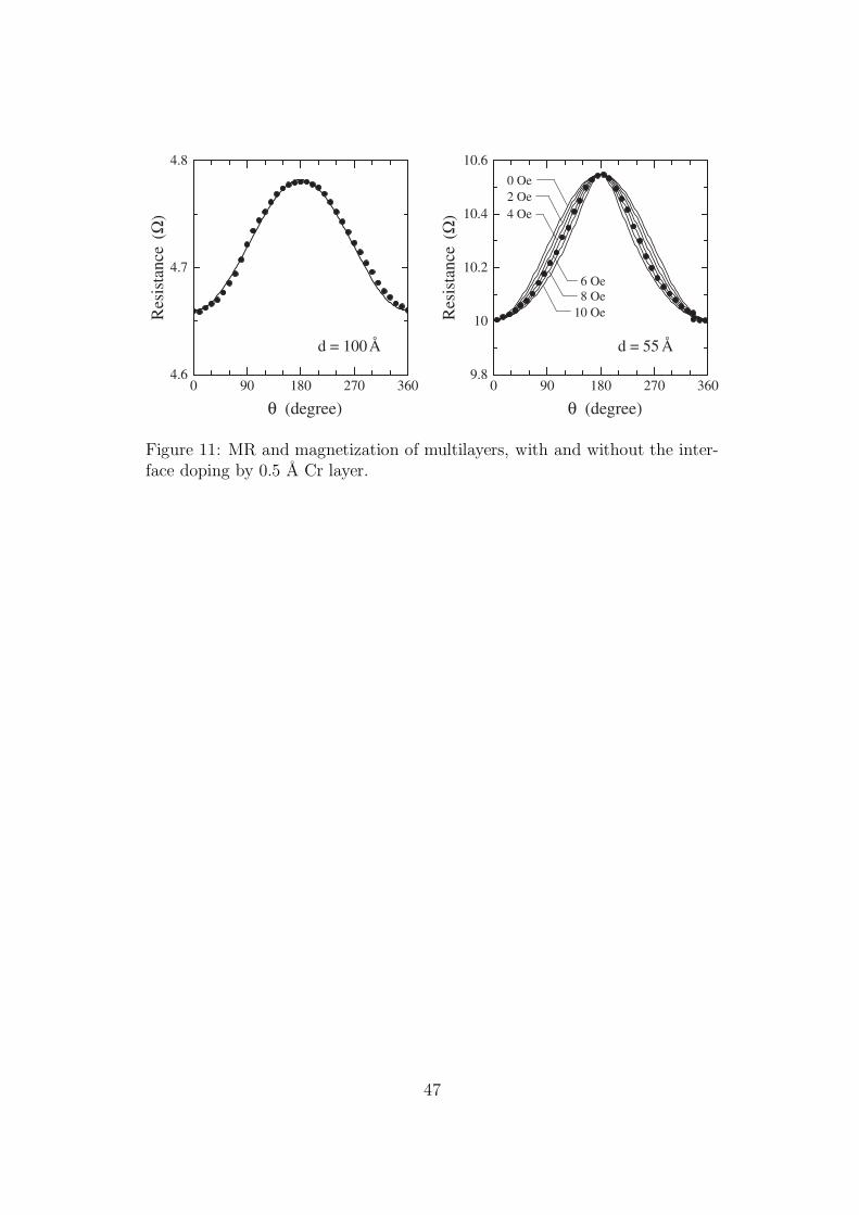
0 90 180 270 360
θ (degree)
9.8
10
10.2
10.4
10.6
d = 55 Å
0 90 180 270 360
θ (degree)
4.6
4.7
4.8R
esis
tanc
e(Ω
)
Res
ista
nce
(Ω)
d = 100Å
8 Oe6 Oe
10 Oe
0 Oe
4 Oe2 Oe
Figure 11: MR and magnetization of multilayers, with and without the inter-face doping by 0.5 A Cr layer.
47
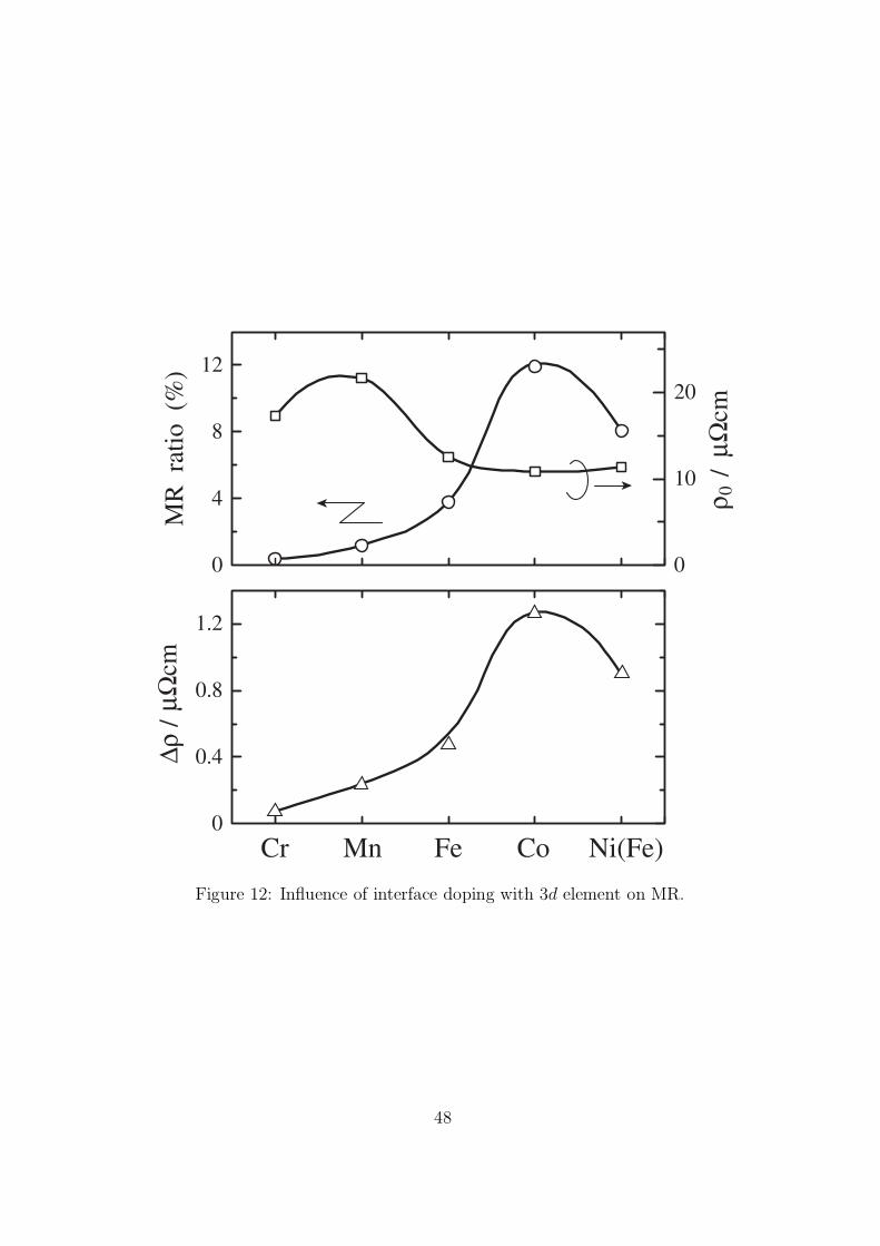
0
0.4
0.8
1.2
∆ρ/
µΩcm
Cr Mn Fe Co Ni(Fe)
0
4
8
12
MR
rat
io (
%)
0
10
20
ρ 0 /
µΩ
cm
Figure 12: Influence of interface doping with 3d element on MR.
48
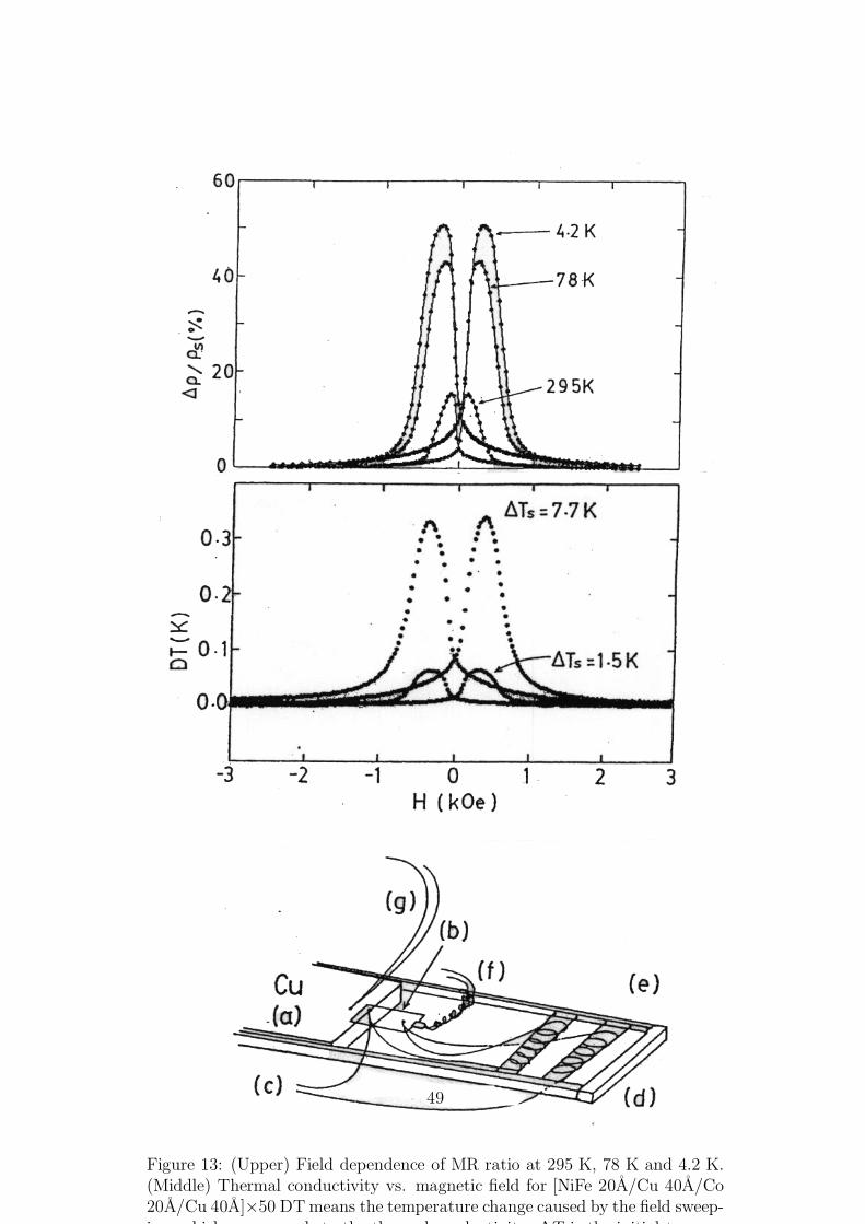
Figure 13: (Upper) Field dependence of MR ratio at 295 K, 78 K and 4.2 K.(Middle) Thermal conductivity vs. magnetic field for [NiFe 20A/Cu 40A/Co20A/Cu 40A]×50 DTmeans the temperature change caused by the field sweep-i hi h d t th th l d ti it ∆T i th i iti l t
49

–1200 –600 0 600 1200
H (Oe)
0
S (µ
V/K
)
–3.0
–2.5 T=80K
Cu/Co/Cu/Ni(Fe)
Figure 14: Thermopower at 80 K of Cu/Co/Cu/NiFe as a function of magneticfield.
50
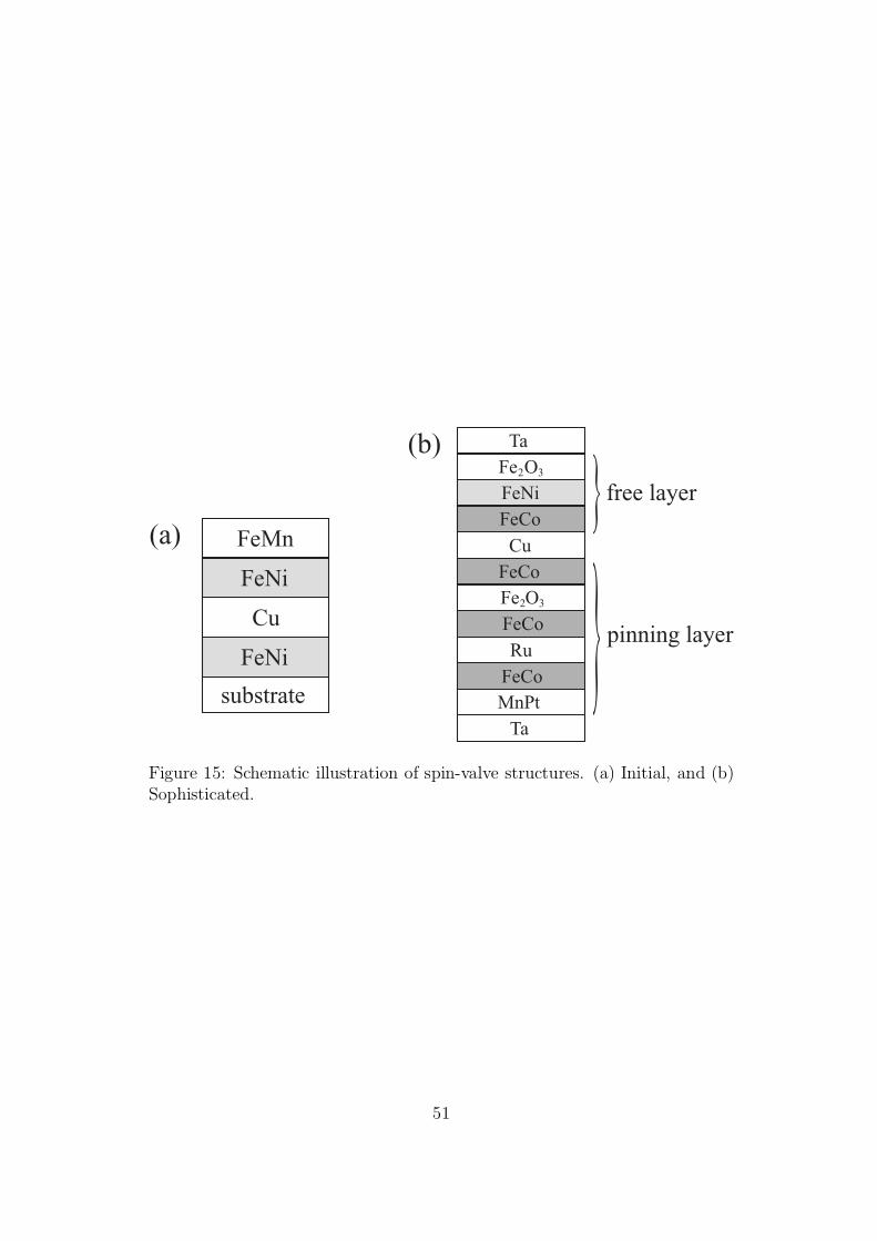
FeMn
FeNi
Cu
FeNi
TaFe OFeNiFeCo
FeCo
substrate
(a)
(b)2 3
Cu
Fe OFeCo
2 3
FeCoRu
MnPtTa
free layer
pinning layer
Figure 15: Schematic illustration of spin-valve structures. (a) Initial, and (b)Sophisticated.
51
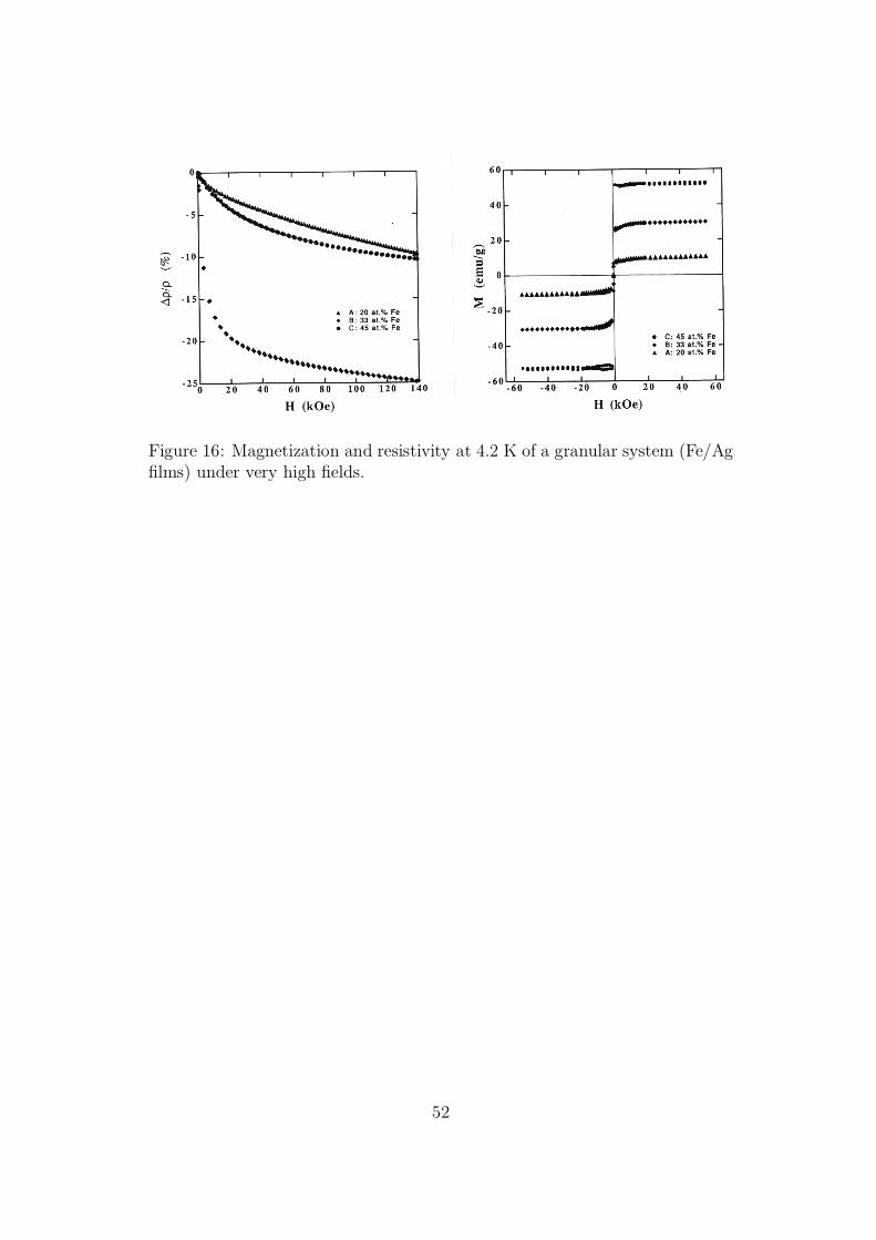
Figure 16: Magnetization and resistivity at 4.2 K of a granular system (Fe/Agfilms) under very high fields.
52
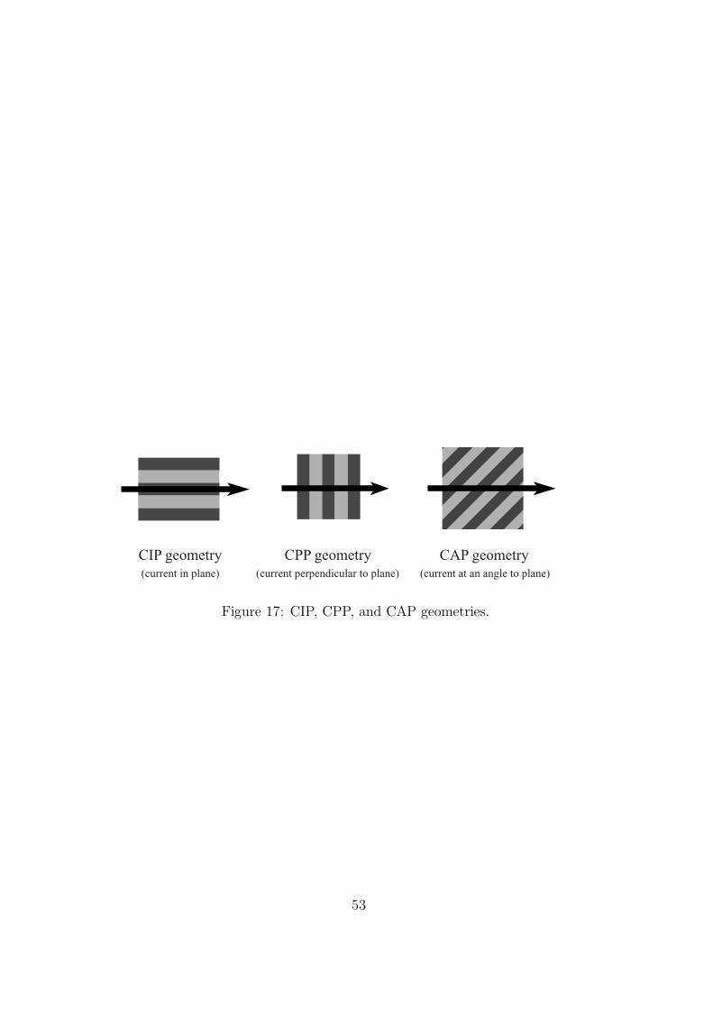
CIP geometry(current in plane)
CAP geometry(current at an angle to plane)
CPP geometry(current perpendicular to plane)
Figure 17: CIP, CPP, and CAP geometries.
53
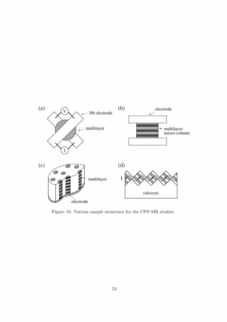
Imultilayer
electrode
substrate
multilayermicro-column
multilayer
Nb electrodeelectrode(a)
(c)
(b)
(d)
V
I
Figure 18: Various sample structures for the CPP-MR studies.
54
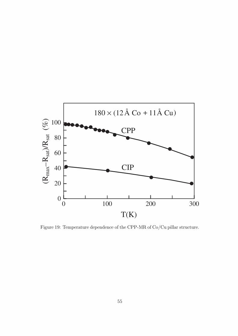
0 100 200 300
T(K)
0
20
40
60
80
100
(Rm
ax–
Rsa
t)/R
sat
(%)
CIP
CPP
180 × (12Å Co + 11Å Cu)
Figure 19: Temperature dependence of the CPP-MR of Co/Cu pillar structure.
55
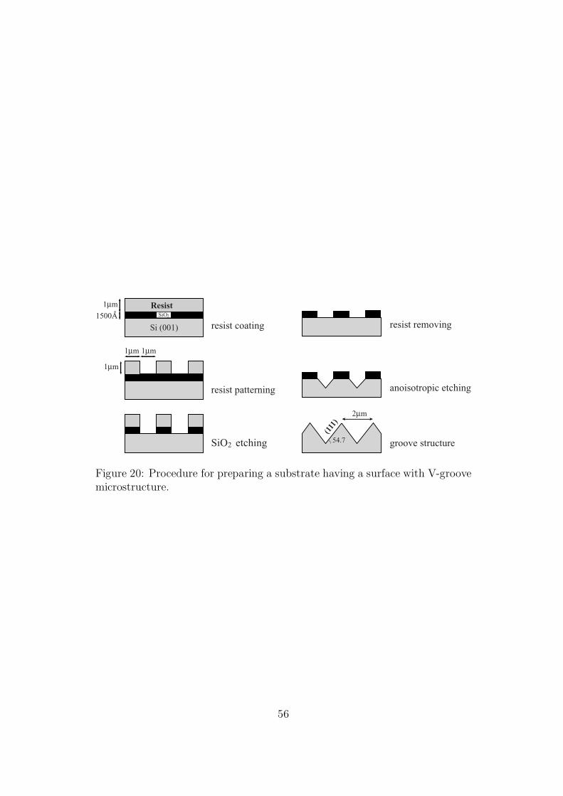
Si (001)
ResistSiO2
2µm
(111
)
54.7
1µm 1µm
1µm
1µm
1500Aresist coating resist removing
anoisotropic etching
groove structure
resist patterning
SiO etching2
Figure 20: Procedure for preparing a substrate having a surface with V-groovemicrostructure.
56
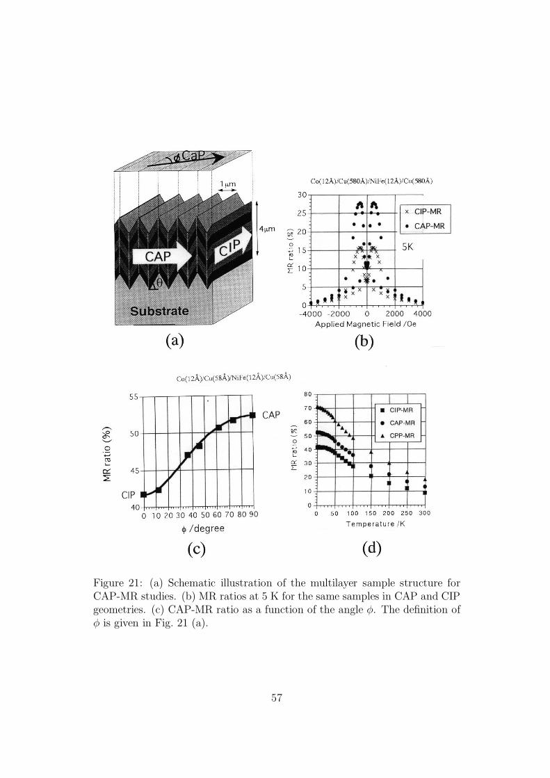
Figure 21: (a) Schematic illustration of the multilayer sample structure forCAP-MR studies. (b) MR ratios at 5 K for the same samples in CAP and CIPgeometries. (c) CAP-MR ratio as a function of the angle φ. The definition ofφ is given in Fig. 21 (a).
57
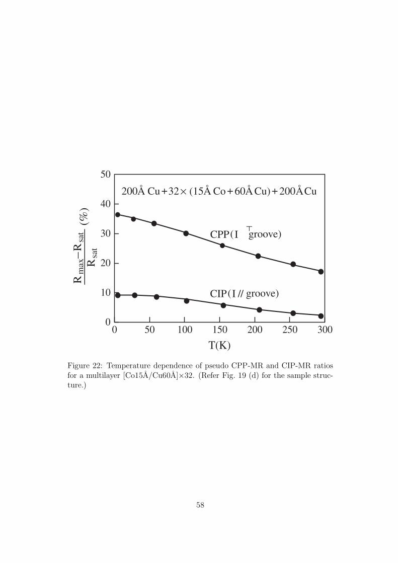
0 50 100 150 200 250 300
T(K)
0
10
20
30
40
50
Rm
ax–
Rsa
tR
sat
(%)
CIP( I // groove)
CPP( I groove)
200Å Cu +32 × (15Å Co + 60Å Cu) + 200ÅCu
a
Figure 22: Temperature dependence of pseudo CPP-MR and CIP-MR ratiosfor a multilayer [Co15A/Cu60A]×32. (Refer Fig. 19 (d) for the sample struc-ture.)
58
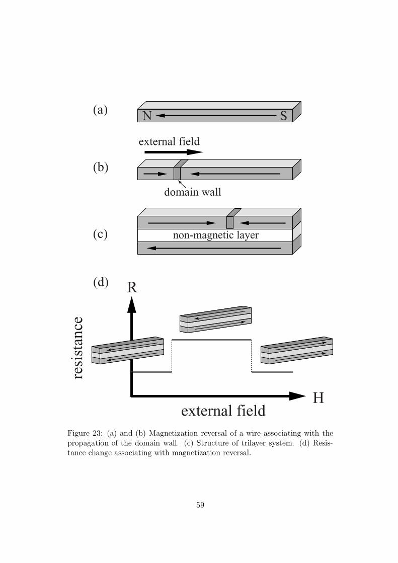
R
Hexternal field
resi
stan
ce
non-magnetic layer
domain wall
external field
(a)
(b)
(c)
(d)
SN
Figure 23: (a) and (b) Magnetization reversal of a wire associating with thepropagation of the domain wall. (c) Structure of trilayer system. (d) Resis-tance change associating with magnetization reversal.
59
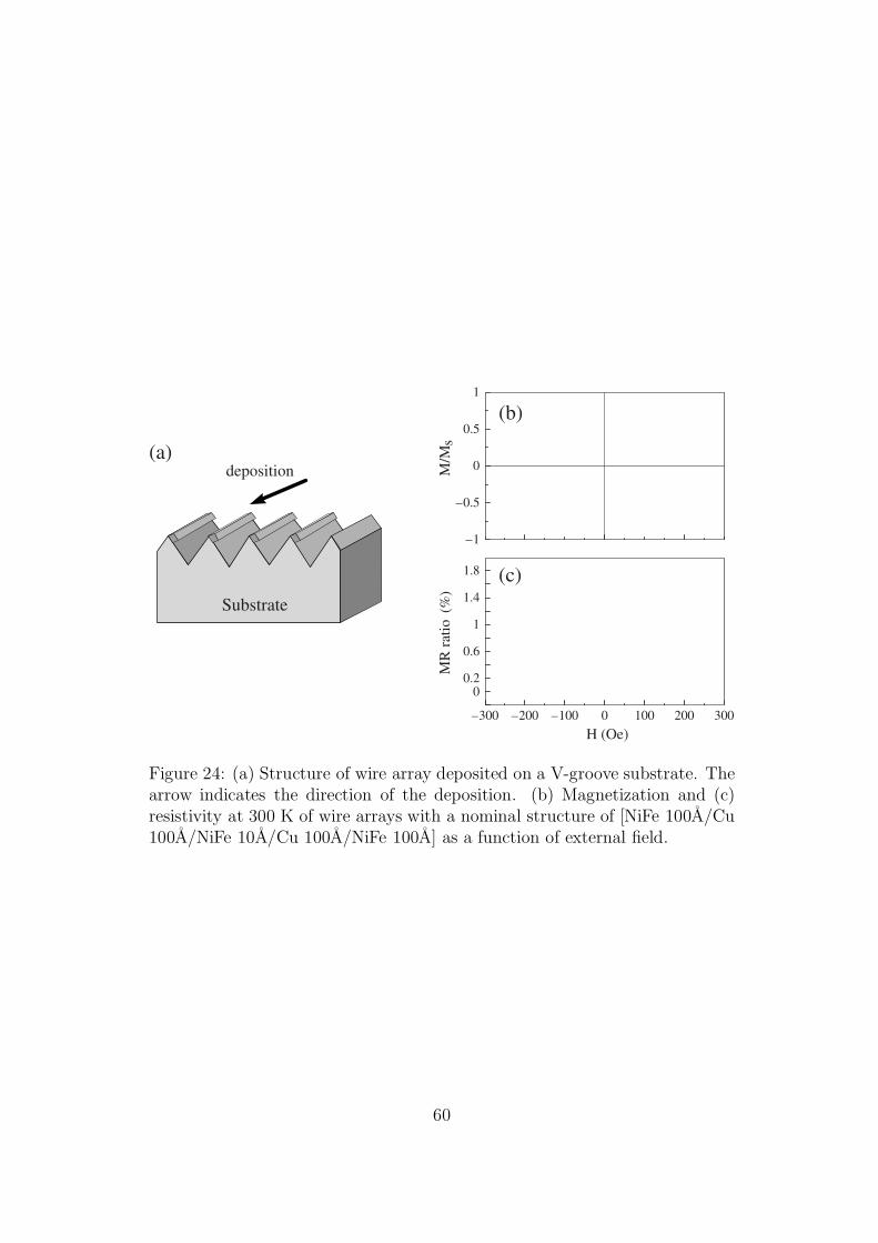
Substrate
deposition(a)
(b)
(c)
–300 –200 –100 0 100 200 300
H (Oe)
00.2
0.6
1
1.4
1.8
MR
rat
io (
%)
–1
–0.5
0
0.5
1
M/M
s
Figure 24: (a) Structure of wire array deposited on a V-groove substrate. Thearrow indicates the direction of the deposition. (b) Magnetization and (c)resistivity at 300 K of wire arrays with a nominal structure of [NiFe 100A/Cu100A/NiFe 10A/Cu 100A/NiFe 100A] as a function of external field.
60
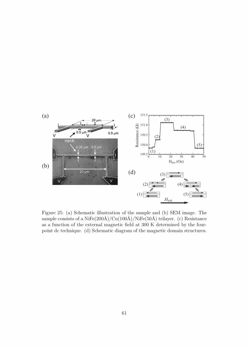
(a)
(b)
(c)
(d) (3)
(2) (4)
(1) (5)Hext
(3)
(2)
(4)
(1)
(5)Res
ista
nce
(Ω)
Hext (Oe)
151.5
151.0
150.5
150.0
149.50 10 20 30 40 50
Figure 25: (a) Schematic illustration of the sample and (b) SEM image. Thesample consists of a NiFe(200A)/Cu(100A)/NiFe(50A) trilayer. (c) Resistanceas a function of the external magnetic field at 300 K determined by the four-point dc technique. (d) Schematic diagram of the magnetic domain structures.
61
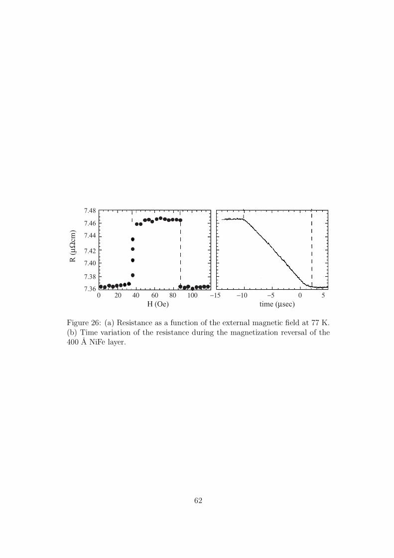
R (
µΩcm
)
Η (Oe) time (µsec)0 20 806040 100 −15 −10 50−5
7.36
7.38
7.40
7.42
7.44
7.46
7.48
Figure 26: (a) Resistance as a function of the external magnetic field at 77 K.(b) Time variation of the resistance during the magnetization reversal of the400 A NiFe layer.
62
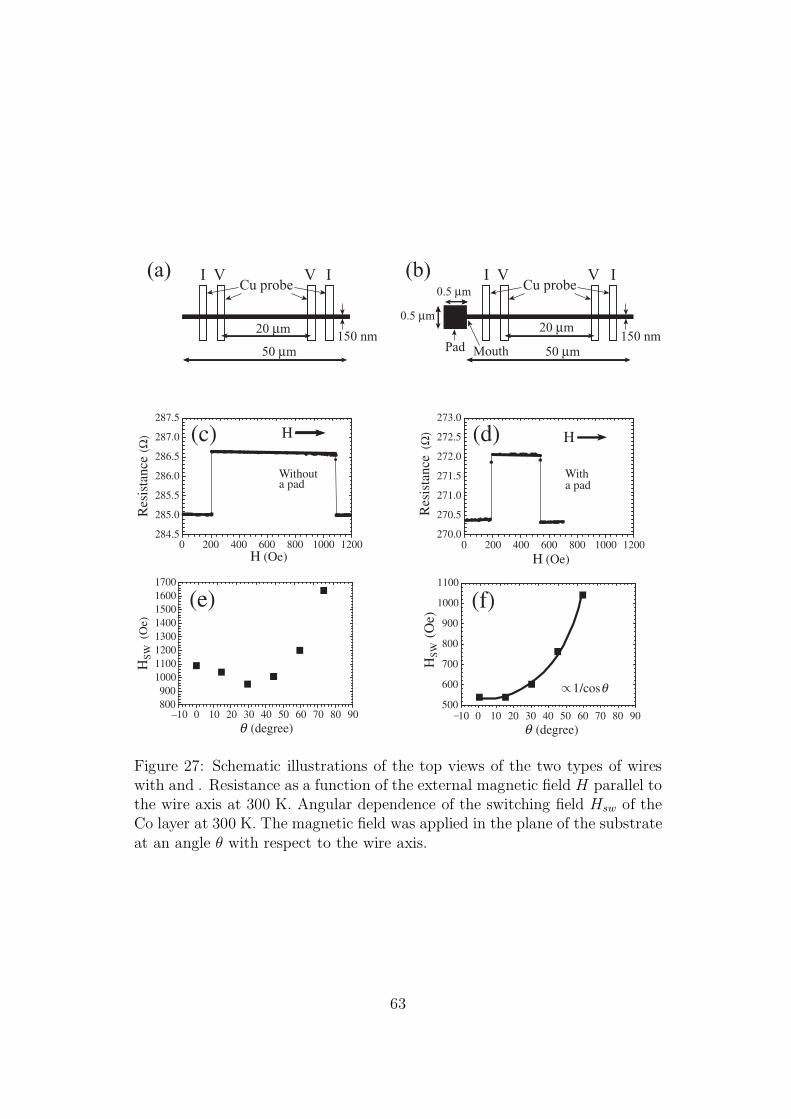
Cu probeI IV V
Pad Mouth150 nm
20 µm
0.5 µm
0.5 µm
50 µm
(b)Cu probe
I IV V
150 nm20 µm
50 µm
(a)
–10 0 10 20 30 40 50 60 70 80 90θ (degree)
800900
10001100120013001400150016001700
–10 0 10 20 30 40 50 60 70 80 90θ (degree)
500
600
700
800
900
1000
1100
HS
W (O
e)
1/cosθ/
HS
W
(Oe)
(e) (f)
(c) (d)
284.5
285.0
285.5
286.0
286.5
287.0
287.5
H
Withouta pad
0 200 400 600 800 1000 1200H (Oe)
0 200 400 600 800 1000 1200H (Oe)
270.0
270.5
271.0
271.5
272.0
272.5
273.0R
esis
tanc
e(Ω
)
(Ω)
Witha pad
H
Res
ista
nce
Figure 27: Schematic illustrations of the top views of the two types of wireswith and . Resistance as a function of the external magnetic field H parallel tothe wire axis at 300 K. Angular dependence of the switching field Hsw of theCo layer at 300 K. The magnetic field was applied in the plane of the substrateat an angle θ with respect to the wire axis.
63