Embed Size (px)
Citation preview

T270
C270
WARNING!n Tominimizetheriskofinjurytoyourselfandothers,read
thismanualandfamiliarizeyourselfwithitscontents.n Alwaysweareyeprotectionwhenoperatingthisunit!
Part Number 62057-94310 Rev. 1/08
SHINDAIWA OWNER’S/OPERATOR’S MANUAL
T270 GRASS TRIMMERC270 BRUSHCUTTER

2
General Safety InstructionsAttention Statements
Contents
Throughout this manual are special “Attention Statements”.
IMPORTANT!The operational procedures described in this manual are intended to help you get the most from this unit, and to protect you and others from harm. These procedures are guidelines for safe operation under most con-ditions, and are not intended to replace any safety rules and/or laws that may be in force in your area. If you have questions regard-ing your 270 series unit, or if you do not understand something in this manual, your Shindaiwa dealer will be glad to assist you. You may also contact Shindaiwa Inc. at the address printed on the back of this manual.
CAUTION!Astatementprecededbytheword“CAUTION”containsinformationthatshouldbeactedupontoavoiddamag-ingyour270-seriesunit.
IMPORTANT!A statement preceded by the word “IMPORTANT” is one that possesses spe-cial significance.
NOTE:Astatementprecededbytheword“NOTE”containsinformationthatishandytoknowandmaymakeyourjobeasier.
Introduction
PAGE
The Shindaiwa 270 series of hand-held power tools has been designed and built to deliver superior performance and reliability without compromise to quality, comfort, or durability.
Shindaiwa high performance engines rep-resent the leading edge of 2-cycle engine technology, delivering exceptionally high power from remarkably low displacement and weight. As an owner/operator, you’ll soon discover for yourself why Shindaiwa is simply in a class by itself!
IMPORTANT!The information contained in this manual describes units available at the time of publication.
While every attempt has been made to give you the very latest information about your Shindaiwa product, there may be some differences between your 270 series unit and what is described here. Shindaiwa Inc. reserves the right to make changes to products without prior notification, and without obligation to make alterations to units previously manufactured.
WARNING!TheengineexhaustfromthisproductcontainschemicalsknowntotheStateofCaliforniatocausecancer,birthdefectsorotherreproductiveharm.
WARNING!Astatementprecededbythetrian-gularattentionsymbolandtheword“WARNING”containsinformationthatshouldbeactedupontopreventseri-ousbodilyinjury.
Read and follow thisoperators manual.Failure to do so couldresult in serious injury.
Wear eye and hearingprotection at all timesduring the operation of this unit.
Keep bystandersat least 50 feet (15 m)away during operation.
Beware of thrown or ricocheted objects.
Do not operate this unit with a blade unless the unit is equipped with a Shindaiwa-approvedhandlebar or barrier.
Always wear a harness when operating this unit with a blade. A harness is also recommended when using trimmer line.
If unit is used as a brushcutter, beware of blade thrust. A jammedblade can cause the unit to jerk suddenly and may cause the operator to lose control of the unit.
Work SafelyTrimmers and brushcutters run at very high speeds and can do serious damage or injury if they are misused or abused. Never allow a person without training or instruction to operate this unit!
WARNING! USE GOOD JUDGMENT
ALWAYSweareyeprotectiontoshieldagainstthrownobjects.NEVERruntheenginewhentrans-portingtheunit.NEVERruntheengineindoors!Makesurethereisalwaysgoodventilation.Fumesfromengineexhaustcancauseseriousinjuryordeath.ALWAYSclearyourworkareaoftrashorhiddendebristhatcouldbethrownbackatyouortowardabystander.ALWAYSusethepropercuttingtoolforthejob.ALWAYSstoptheengineimmediatelyiftheunitsuddenlybeginstovibrateorshake.Inspectforbroken,missingorimproperlyinstalledpartsorattachments.NEVERextendtrimminglinebeyondthe length specified for your unit.ALWAYSkeeptheunitascleanaspractical.Keepitfreeofloosevegeta-tion,mud,etc.ALWAYS hold the unit firmly with both handswhencuttingortrimming,andmaintaincontrolatalltimes.ALWAYSkeepthehandlesclean.ALWAYSdisconnectthesparkplugwirebeforeperforminganymaintenancework.ALWAYS,ifasawbladeshouldbindfastinacut,shutofftheengineimme-diately.Pushthebranchortreetoeasethebindandfreetheblade.
WARNING!Nevermakeunauthorizedattachmentinstallations.
General Safety Instructions................... 3Product Description ............................... 5Specifications T270/C270 ..................... 5Assembly ................................................. 6Mixing Fuel........................................... 10Filling the Fuel Tank .......................... 10Starting the Engine ............................. 11Stopping the Engine............................. 11Adjusting Engine Idle .......................... 12Check Unit Condition .......................... 12Maintenance ......................................... 15Long Term Storage .............................. 17Blade Sharpening ................................. 17Troubleshooting Guide ....................... 18Limited Warranty Statement ............... 21

3
WARNING!Neveroperatepowerequipmentofanykindifyouaretiredorifyouareunder the influence of alcohol, drugs, medicationoranyothersubstancethatcouldaffectyourabilityorjudgement.
WARNING!
MINIMIzE THE RISk Of fIRE!
NEVER smoke or light fires near the trimmerorbrushcutter.ALWAYS stoptheengineandallowitto cool before refueling. Avoid overfill-ingandwipeoffanyfuelthatmayhavespilled.ALWAYS inspecttheunitforfuelleaksbeforeeachuse.Duringeachrefill, check that no fuel leaks from aroundthefuelcapand/orfueltank.Iffuelleaksareevident,stopusingtheunitimmediately.Fuelleaksmustberepairedbeforeusingtheunit.ALWAYS movetheunittoaplacewellawayfromafuelstorageareaorotherreadily flammable materials before startingtheengine.NEVER place flammable material close to the engine muffler.NEVERoperatetheenginewithoutthesparkarresterscreeninplace.
Stay AlertYou must be physically and mentally fit to operate this unit safely.
General Safety Instructions The Properly Equipped Operator
Figure 1
Always wear a harness when operating a unit equipped with
a blade.
Wear appropriate footwear (non-skid boots or shoes): do not wear open-toed shoes or
sandals. Never work barefooted!
Wear hearing protection devices and a broad-brimmed hat or helmet.
Wear close-fitting clothing to protect legs and arms. Gloves offer added protection and are strongly recommended. Do not
wear clothing or jewelry that could get caught in machinery or underbrush. NEVER wear
shorts!
Always wear eye protection such as goggles or safety glasses.
Always operate with both hands firmly gripping the
machine.
When operating with a blade, make sure the handle is positioned to
provide you with maximum protection from contacting the blade.
Keep away from the rotating trimming line or blade at all times, and never lift a moving attachment
above waist-high.
Keep a proper footing and do not overreach—maintain your balance
at all times during operation.
Always make sure the appropriate cutting attachment shield is correctly
installed.

4
Safety Labels
Figure 3
IMPORTANT!Safety and Operation Information Labels: Make sure all information labels are undamaged and readable. Immediately replace damaged or missing information labels. New labels are available from your local authorized Shindaiwa dealer.
T270
C270
Be Aware of the Working Environment
Avoid long-term operation in very hot or very cold
weather. Make sure bystanders or observers outside
the 50-foot “danger zone” wear eye protection.
Be extremely careful of slippery terrain, especially during
rainy weather.
Always make sure the appropriate cutting attachment shield is correctly installed.
Beware of a coasting blade when brushcutting or edging. A coasting blade can injure while
it continues to spin after the throttle trigger is released or after the engine is stopped.
When operating in rocky terrain or near electric wires or fences, use extreme caution
to avoid contacting such items with the cutting attachment.
Be constantly alert for objects and debris that could be thrown either from the rotating cutting attachment or bounced from a hard surface.
If contact is made with a hard object,
stop the engine and inspect the cutting
attachment for damage.
50 fEET Reduce the risk of bystanders being struck by flying debris. Make
sure no one is within 50 feet (15 meters)—that’s about 16 paces—of an operating attachment.
Figure 2
This label indicates the minimum distance between front handle and rear
grip per ANSI B175.3.
5
Product Description
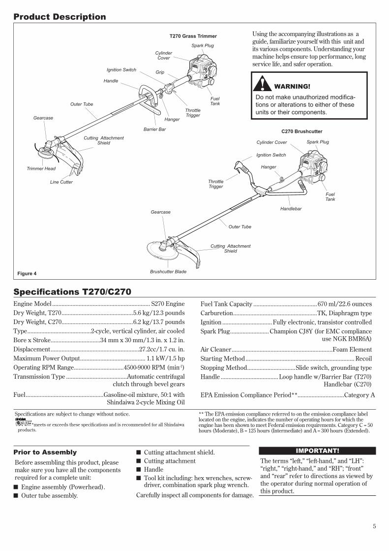
WARNING!Do not make unauthorized modifica-tionsoralterationstoeitheroftheseunitsortheircomponents.
Using the accompanying illustrations as a guide, familiarize yourself with this unit and its various components. Understanding your machine helps ensure top performance, long service life, and safer operation.
Figure 4
Cylinder Cover
C270 Brushcutter
Handlebar
Fuel Tank
ThrottleTrigger
Gearcase
Brushcutter Blade
Cutting Attachment Shield
Outer Tube
Hanger
Spark Plug
Ignition Switch
Engine Model ............................................................... S270 EngineDry Weight, T270 ..............................................5.6 kg/12.3 poundsDry Weight, C270 ..............................................6.2 kg/13.7 poundsType .........................................2-cycle, vertical cylinder, air cooledBore x Stroke ................................34 mm x 30 mm/1.3 in. x 1.2 in.Displacement .........................................................27.2cc/1.7 cu. in.Maximum Power Output .......................................... 1.1 kW/1.5 hpOperating RPM Range ................................4500-9000 RPM (min-1)Transmission Type .......................................Automatic centrifugal clutch through bevel gears
Fuel ..................................................Gasoline-oil mixture, 50:1 with Shindaiwa 2-cycle Mixing Oil
Fuel Tank Capacity .........................................670 ml/22.6 ouncesCarburetion ......................................................TK, Diaphragm typeIgnition ................................ Fully electronic, transistor controlledSpark Plug .........................Champion CJ8Y (for EMC compliance
use NGK BMR6A)
Air Cleaner .................................................................Foam ElementStarting Method ...................................................................... RecoilStopping Method ...............................Slide switch, grounding typeHandle ..................................... Loop handle w/Barrier Bar (T270)
Handlebar (C270)
EPA Emission Compliance Period**..............................Category A
Specifications T270/C270
Prior to AssemblyBefore assembling this product, please make sure you have all the components required for a complete unit:n Engine assembly (Powerhead).n Outer tube assembly.
IMPORTANT!The terms “left,” “left-hand,” and “LH”: “right,” “right-hand,” and “RH”; “front” and “rear” refer to directions as viewed by the operator during normal operation of this product.
Specifications are subject to change without notice.
n Cutting attachment shield.n Cutting attachment n Handlen Tool kit including: hex wrenches, screw-
driver, combination spark plug wrench.
Carefully inspect all components for damage.
Hanger
T270 Grass Trimmer
Handle
ThrottleTrigger
Cutting Attachment Shield
Outer Tube
Grip
Gearcase
Barrier Bar
Fuel Tank
Cylinder Cover
Spark Plug
Ignition Switch
Trimmer Head
Line Cutter
*meets or exceeds these specifications and is recommended for all Shindaiwa products.
** The EPA emission compliance referred to on the emission compliance label located on the engine, indicates the number of operating hours for which the engine has been shown to meet Federal emission requirements. Category C = 50 hours (Moderate), B = 125 hours (Intermediate) and A = 300 hours (Extended).

6
The throttle lever free play should be approx-iamtely 7mm. See Figure 5. Make sure that the throttle lever operates smoothly without binding. If it becomes necessary to adjust the lever freeplay, follow the procedures and illustrations that follow.
Adjusting free Play
27043
7 mm Free Play Cable
Adjuster
Locknut
Figure 5
Handle T270
1. Position the handle on the outer tube forward of Handle Positioning Label as shown in Figure 6.
2. Install the handle and barrier bar onto the outer tube with the socket head cap screws and nuts as shown in Figure 6. Tighten the screws finger-tight ONLY at this time.
3. Locate the handle in the best position for operator comfort (usually about 10 inches ahead of the throttle housing).
4. Secure the handle by alternately tight-ening the four socket-head screws in a diagonal or “crisscross” fashion.
27007
Handle
Barrier Bar
Handle Retaining Screws
Outer Tube
Figure 6
Handle Positioning Label
Nuts
Assembly
1. Loosen the lock nut on the cable adjuster. See Figure 5.
2. Turn the cable adjuster in or out as required to obtain proper free play of 9/32 inch (7mm). See Figure 5.
3. Tighten the locknut.
Handle C270
1. Use the 4 mm hex wrench to remove the lower cap retaining screws from the handlebar bracket. Remove the cap from the bracket, and note the position of the two spacers installed between the bracket halves. See Figure 7.
2. Position the handle on the outer tube forward of Handle Positioning Label as shown in Figure 7. Reassemble the lower cap to the handlebar bracket in the reverse order of disassembly.
3. Locate the handle in the best position for operator comfort.
4. Firmly tighten both lower cap retaining screws.
27008
Handlebar
Spacer
Lower Cap Retaining Screws
Lower Cap
Figure 7
Handle Positioning Label

7
Assembly (continued)Cutting Attachment Shield T270/C270
WARNING!Thelinecutterisverysharp.Wearglovestoprotectyourhandswhenhandling.
To Change Position of Line Cutter.
1. Remove the 2 hex screws with a 4 mm hex wrench. See Figure 10.
2. Rotate line cutter. See Figure 10.
3. Reinstall the two hex screws and tighten them securely.
NOTE:Be careful to not lose the 2 nuts in the cutting attachment shield, they are not captured.
The line cutter can be positioned in 2 positions to obtain different line length for cutting.
Figure 8
Line Cutter
Figure 8A
HexScrews
1. Insert the cutting attachment shield between the outer tube and the cut-ting attachment shield mounting plate. See Figure 8.
WARNING!NEVERoperatetheunitwithoutthecuttingattachmentshieldinstalledandtightlysecured!
CAUTION!Makesuretheclampscrewandretain-ingnutaresecurelytightenedbeforetighteningthefoursocket-headcapscrews.NOTE:
Itmaybenecessarytoloosentheretain-ingnutandclampscrewtoadjustcuttingattachmentshieldmountingplate.2. Fit the two shims and the bracket over
the outer tube and loosely install the four socket-head cap screws. See Figure 8.
Sub-Shield T270, C270 (when trim-mer head is in use)1. Attach the shield extension to the cut-
ting attachment shield.
WARNING!NEVERusethismachinewithoutsub-shieldwhenusingatrimmerhead.
CAUTION!Makesurethesub-guardiscompletelyhookedatthehookreceiver.
Sub-shield
Hook
HookReceiver
Cutting Attachment Shield
Shim
Shim
Nut
Upper Clamp
Cutting Attachment
Shield
3. Tighten the four socket-head cap screws to secure the cutting attachment shield.
Cutting Attachment Shield Mounting Plate
Socket-head Cap Screws
Figure 10
Figure 9

8
27017
27016
2701427014
Trimmer Head T270/C270NOTE:
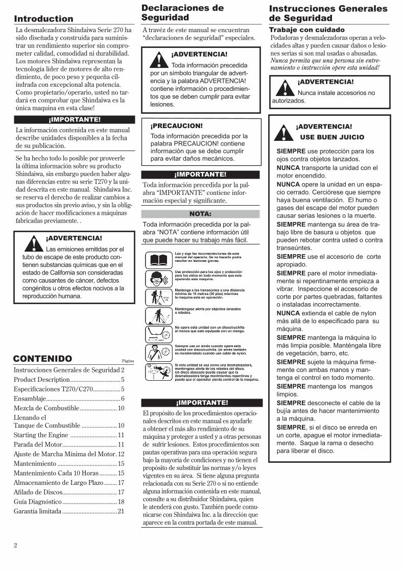
TheT/C270isshippedwithHolderA,thebladeretainer,HolderB,andalsotheshaftboltandboltguardinstalled.TheshaftboltisaLEFT-HANDthreadandisremovedinaCLOCKWISEROTATION.
Install Holder A
Install Holder B
Holder BHolder A
Hex Wrench
Hand-tighten trimmer head
Safety Clip
The T270 should now be completely assembled.
Figure 11
Figure 12 Figure 13
Assembly (continued)
Position the gearcase with the out-put shaft facing up and remove both holders.
Position Holder A as shown and slide it onto the gearcase shaft. See Figure 11.
Install and center the safety clip on the gearcase shaft. See Figure 11.
Install Holder B on the gearcase shaft. The machined boss on Holder A must engage with the recess on Holder B. See Figure 11.
Rotate the gearshaft and holders until the hole in Holder A aligns with the matching hole in the gearcase flange, and then lock the holder to the gearcase by inserting the long end of the hex wrench through both holes. See Figure 12.
Using a counter-clockwise rotation and hand pressure alone, thread and securely tighten the trimmer head into the gearcase shaft. See Figure 13.
Remove the hex wrench from the gearcase and holders.
1.
2.
3.
4.
5.
6.
7.

9
27019B
27018
27019
Brushcutter Blade C270NOTE:
TheC270isshippedwithHolderA,thesafetyclip,HolderB,andalsotheshaftboltandboltguardinstalled.TheshaftboltisaLEFT-HANDTHREADANDISREMOVEDBYTURNINGCLOCKWISE!
Install the Safety Clip Off-
center
Slip the Cutting Blade in Place
Center the Safety Clip
Shaft Bolt
Bolt Guard
Holder B
Gear Shaft
Holder A
Hex Wrench
Figure 14
Assembly (continued)
Safety Clip
Tighten the AssemblyBLADE NOT SHOWN FOR
CLARITY!
Hex Wrench
Install Holder B
Saw Blade
Spark Plug Wrench
Figure 15
The C270 should now be completely assembled.
Turn the C2510 upside down so the gear case output shaft is facing UP and remove the shaft bolt, bolt guard and holder B from the gear case shaft.
1. Align the hole in blade holder A with the matching hole in the gear case flange and then temporarily lock the output shaft by inserting a hex wrench through both holes. See Figure 14.
2. Slide the safety clip off-center. See Figure 14A.
3. Fit the blade over the safety clip and then center it over the flange on holder A. See Figure 14B.
NOTE: Wheninstallingcertainblades,itmaybenecessarytotemporarilyremovethesafetyclip.
CAUTION!Installthebladesoitsprintedsur-faceisvisibletotheoperatorwhenthebrushcutterisinthenormaloperatingposition.
WARNING!The blade must fit flat against the holder flange. The blade mounting hole mustbecenteredovertheraisedbossonbladeholderA.
WARNING!NeveroperatetheC270withoutthesafetyclipinplace!
4. Lock the blade in place by centering the safety clip on the output shaft. See Figure 14C.
IMPORTANT!The machined recess in holder B must completely surround the safety clip, and both holders must be flat against the sur-face of the blade.
5. Install blade holder B on the output shaft. See Figure 15. The recess in the holder must completely cover the safety clip, and must fit tightly against the blade.
6. Install the bolt guard and then the blade retaining bolt. Using the combination spark plug wrench/screwdriver, tighten the bolt firmly in a counter-clockwise direction.
7. Remove the hex wrench.
Figure 14A
Figure 14B Figure 14C

10
Mixing fuel
n STopenginebeforerefueling.n ALWAYSallowtheenginetocool
beforerefueling!n Wipeallspilledfuelandmovethe
engineatleast10feet(3meters)fromthefuelingpointandsourcebeforerestarting!
n NEVERstartoroperatethisunitifthereisafuelleakorthecarbure-tor,fuellines,fueltankand/orfuelcaparedamaged.
n NEVER smoke or light any fires neartheengineorfuelsource!
n NEVER place any flammable mate-rial near the engine muffler!
n NEVERoperatetheenginewithoutthe muffler and spark arrester in goodworkingcondition.
filling the fuel Tank
IMPORTANT!Mix only enough fuel for your immediate needs! If fuel must be stored longer than 30 days and oil with fuel stabilizer is not used, it should first be treated with a fuel stabilizer such as STA-BIL™.
CAUTION!Thisengineisdesignedtooperateona50:1mixtureconsistingofunleadedgasolineand2-cyclemixingoilonly.Useofnon-approvedmixingoilscanleadtoexcessivecarbondeposits.
CAUTION!n Neveruseanytypeofgasoline
containingmorethan10%alcoholbyvolume!Sometypesofgasolinecontainalcoholasanoxygenate.Oxygenatedgasolinemaycauseincreasedoperatingtemperatures.Undercertainconditions,alcohol-basedgasolinemayalsoreducethelubricatingqualitiesofsome2-cyclemixingoils.
n Genericoilsandsomeoutboardoilsmaynotbeintendedforuseinhigh-performance2-cycletypeengines,andshouldneverbeusedinyourShindaiwaengine.
n Use only fresh, clean unleaded gasoline with a pump octane of 87 or higher.
n Mix with 50:1 Shindaiwa Premium 2-cycle mixing oil or with an equivalent high quality 2-cycle mixing oil.
Examples of 50:1 mixing quanti-tiesn 1 gallon of gasoline to 2.6 oz. mixing oil.
n 5 liters of gasoline to 100 ml. mixing oil.
WARNING!
Minimize the Risk of fire!1. Place the trimmer on a flat, level
surface.
2. Clear any dirt or other debris from around the fuel filler cap.
3. Remove the fuel cap, and fill the tank with clean, fresh fuel.
4. Reinstall the fuel filler cap and tighten firmly.
11
27025
Choke Control (closed position)
Starting the Engine
5. While holding the outer tube firmly with one hand, slowly pull the recoil starter handle until resistance is felt, then pull quickly to start the engine. See Figure 19.
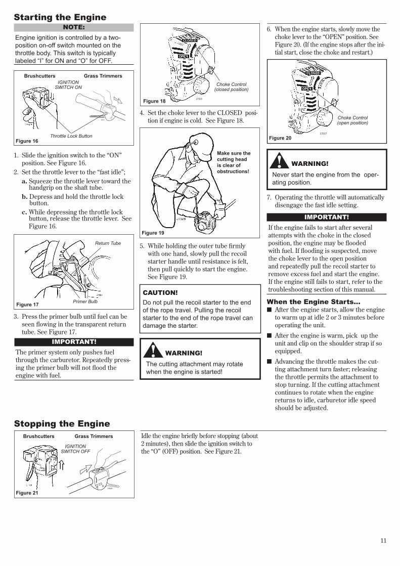
1. Slide the ignition switch to the “ON” position. See Figure 16.
2. Set the throttle lever to the “fast idle”; a. Squeeze the throttle lever toward the
handgrip on the shaft tube. b. Depress and hold the throttle lock
button. c. While depressing the throttle lock
button, release the throttle lever. See Figure 16.
3. Press the primer bulb until fuel can be seen flowing in the transparent return tube. See Figure 17.
4. Set the choke lever to the CLOSED posi-tion if engine is cold. See Figure 18.
Make sure the cutting headis clear of obstructions!
NOTE:Engineignitioniscontrolledbyatwo-positionon-offswitchmountedonthethrottlebody.Thisswitchistypicallylabeled“I”forONand“O”forOFF.
Figure 18
Figure 19
IMPORTANT! The primer system only pushes fuel through the carburetor. Repeatedly press-ing the primer bulb will not flood the engine with fuel.
CAUTION! Donotpulltherecoilstartertotheendoftheropetravel.Pullingtherecoilstartertotheendoftheropetravelcandamagethestarter.
Brushcutters
Throttle Lock Button
Grass TrimmersIGNITION
SWITCH ON
Figure 16
Primer Bulb
Return Tube
Figure 17
27021
WARNING!Neverstarttheenginefromtheoper-atingposition.
WARNING!Thecuttingattachmentmayrotatewhentheengineisstarted!
When the Engine Starts...n After the engine starts, allow the engine
to warm up at idle 2 or 3 minutes before operating the unit.
n After the engine is warm, pick up the unit and clip on the shoulder strap if so equipped.
n Advancing the throttle makes the cut-ting attachment turn faster; releasing the throttle permits the attachment to stop turning. If the cutting attachment continues to rotate when the engine returns to idle, carburetor idle speed should be adjusted.
IMPORTANT!If the engine fails to start after several attempts with the choke in the closed position, the engine may be flooded with fuel. If flooding is suspected, move the choke lever to the open position and repeatedly pull the recoil starter to remove excess fuel and start the engine. If the engine still fails to start, refer to the troubleshooting section of this manual.
6. When the engine starts, slowly move the choke lever to the “OPEN” position. See Figure 20. (If the engine stops after the ini-tial start, close the choke and restart.)
Figure 2027027
Choke Control (open position)
Idle the engine briefly before stopping (about 2 minutes), then slide the ignition switch to the “O” (OFF) position. See Figure 21.
Stopping the Engine
Figure 21
7. Operating the throttle will automatically disengage the fast idle setting.
Brushcutters
IGNITION SWITCH OFF
27029
Grass Trimmers

12
Adjusting Engine IdleThe engine must return to idle speed whenever the throttle lever is released. Idle speed is adjustable, and must be set low enough to permit the engine clutch to disengage the cutting attachment when the throttle is released.
Adjustment Procedure1. Start the engine, and then allow it to
idle 2-3 minutes until warm.
2. If the cutting attachment rotates at engine idle, reduce idle speed by turn-ing the idle adjustment screw counter clockwise. See Figure 22.
3. If a tachometer is available, the engine idle speed should be final-adjusted to 3,000 (±250) RPM (min-1).
WARNING!ThecuttingattachmentmustNEVERrotateatengineidlespeeds!
NOTE:Carburetormixtureadjustmentsarepre-setatthefactoryandcannotbeservicedin the field.
27030
Idle Adjusting Screw (All Units)
Figure 22
Slow Air Screw(Non-Emission
Compliance Units Only)
Main Carburetor Adjustment Screw
(Non-Emission Compliance Units Only)
NEVER operate the unit with the cut-ting attachment shield or other protective devices (harness, ignition switch, blade retention clip, etc.) removed!
WARNING!Acuttingattachmentshieldorotherprotectivedeviceisnoguaranteeofprotectionagainstthrownobjects.YOUMUSTALWAYSGUARDAGAINSTFLYINGDEBRIS!
Check Unit ConditionUse only authorized Shindaiwa parts and accessories with your Shindaiwa trimmer or brushcutter. Do not make modifications to the unit without the written approval of Shindaiwa Inc.
ALWAYS make sure the cutting attach-ment is properly installed and firmly tight-ened before operation.
NEVER use a cracked or warped cutting attachment: replace it with a serviceable one.
ALWAYS make sure the cutting attach-ment fits properly into the appropriate cutter holder. If a properly installed attach-ment vibrates, replace the attachment with a new one and re-check.
ALWAYS stop the engine immediately and check for damage if you strike a for-eign object or if the unit becomes tangled. Do not operate with broken or damaged equipment.
NEVERallow the engine to run at high RPM’s without a load. Doing so could damage the engine.
NEVERoperate a unit with worn or dam-aged fasteners or attachment holders.
NEVERcut with dull blades. Doing so will increase the risk of blade thrust and may also damage your equipment.

13
Hold the grass trimmer so the trimmer head is angled slightly into the area to be cut. To ensure maxi-mum trimmer-line service life, cut
only with the tip of the trimmer line. Cut grass by swinging the machine’s trimmer head from right to left. Keep the trimmer head horizontal. See Figure 25.
EdgingTilt the handle about 100° to the right (from horizontal) and move forward, holding the trimmer vertical. See Figure 26.
Shoulder Strap
Shoulder Strap recommended
for use with grass trimmers
NOTE:Althoughashoulderstrapisnotrequiredforusewithatrimmerhead,ashoulderstrapcanincreaseoperatorcomfortdur-ingextendedperiodsofoperation.
WARNING!Alwayswearashoulderstrapwhenoperatingthisunitwithablade.Ashoulderstrapisalsorecommendwhenusingtrimmerline.
IMPORTANT!Adjust the shoulder strap or harness so the shoulder pad rests comfortably on the off-side shoulder and the cutting path of the cutting attachment is parallel to the ground. Make sure all hooks and adjust-ment devices are secure.
C270/ T270 with a Blade
T270 with a Trimmer Head
27032AFigure 23
Figure 24
27033
27034
Cutting Grass—Units Equipped with a Trimmer HeadYour Shindaiwa T270 Grass Trimmer may be equipped with one of several Shindaiwa trimmer head models, each with features for specific applications and/or opera-tional requirements. CAUTION!
Donotpushtherotatinglineintotrees,wirefencesoranymaterialthatcouldtangleorbreaklineends.
n Flail. This device, designed for clearing weeds and light brush, features three ny-lon blades attached to the head by pivots.
CAUTION!OperationatlowRPMcanleadtopre-matureclutchfailure.
Trimming and Mowing Grass
Figure 25
Figure 26
NOTE:A grass trimmer head can also be fitted totheShindaiwaC270Brushcutter.
For proper operation, always refer to the instructions accompanying the trimmer head being used. Available trimmer head styles include:n Semi-automatic. Trimmer line is indexed
when the operator taps the trimmer head on the ground during operation.
n Manual. The operator indexes line manually while the grass trimmer is stopped.
n Fixed. The operator must stop the ma-chine and add new lengths of trimmer line manually.
Engine Operating SpeedsOperate the unit at full throttle while cutting grass.

14
27036
WARNING!Whenmakingverticalcuts,neverallowthebladetoexceedwaistheight.
WARNING!n Whencuttingwoodwithablade,feed
thebladeslowlynever strike or “slam” the spinning blade against the wood.
n DONOTuse2-toothornon-Shindaiwaapproved4-toothcuttingbladeswithShindaiwatrimmersandbrushcutters.
The blade rotates counter-clockwise. For best performance and to minimize being struck by debris, move the blade from right to left while advancing on your work.Position the blade so cuts are made between the blade’s 8 o’clock and 10 o’clock positions (as viewed from above). DO NOT cut between the 10 o’clock and 5 o’clock positions. See Figure 27.
Cut on the left side of the blade.
KEEP YOUR BODY OUTSIDE THE
PATH OF BLADE ROTATION
Hold the brushcutter with the blade at a 90° angle to the ground so the blade’s bottom edge rotates toward the opera-tor. Move the blade from top to bottom through the cut, and cut only with the bot-tom edge of the blade. See Figure 28.
Figure 28
Vertical Cuts
Blade Thrust‘Blade thrust’ is a sudden sideways or backward motion of the brushcutter. Such motion may occur when the blade jams or catches on an object such as a sapling tree or tree stump. BE CONSTANTLY ALERT FOR BLADE THRUST AND GUARD AGAINST ITS EFFECTS!
Brushcutter HandlebarA brushcutter’s handlebar or barrier bar helps prevent the operator from mov-ing forward or the unit moving rear-ward; thus preventing inadvertent bodily contact with the blade. ALWAYS KEEP THE HANDLEBAR OR BARRIER BAR SECURELY IN PLACE ON THE UNIT!
Brushcutter Shoulder StrapA shoulder strap provides additional pro-tection against blade thrust. Plus, a shoul-der strap gives significant support and comfort to help ensure safe and efficient operation.
When operating a trimmer or brushcutter, make sure both the handle and shoulder strap are adjusted to the size of the opera-tor using the unit.
Using A Brushcutter Blade C270
WARNING!n Beforeworkingwithablade-
equippedunit,alwaysinspectandcleantheareaofobjectsthatcouldinterferewithordamagetheblade.
n Neveruseabladenearsidewalks,fenceposts,buildingsorotherobjectsthatcouldcauseinjuryordamage.
n Neveruseabladeforpurposesotherthanthoseforwhichitwasdesigned.
n Wheneveryoustrikeahardobjectwithablade,alwaysstopthebrushcutterandcarefullyinspectthebladefordamage.NEVEROPERATETHEBRUSHCUTTERWITHADAMAGEDBLADE!
n Ablade-equippedunitmustbeequippedwithabicycle-typehan-dlebarorbarrierbaraswellasaharnessorshoulderstrap.
n Alwaysmakesurethecuttingattachmentshieldisproperlyinstalledbeforeoperatingtheunit.
Engine Operating SpeedsOperate the unit at full throttle while cut-ting. Best fuel efficiency is obtained by releasing the throttle when swinging back after a cut.
n To prevent possible engine damage, do not allow the brushcutter to run at high speeds without a load.
n Avoid operating the engine at low speeds. Doing so can lead to rapid clutch wear. In addition, slow-speed operation tends to cause grass and debris to wrap around the cutting head.
Figure 27
DO NOT CUT
TenO'clock
OK To Cut
FiveO'clock
BladeRotation
EightO'clock

15
Daily Maintenance
27037
Priortoeachworkday, perform the following:
Remove and clean the element
10-hour MaintenanceEvery10-Hoursofoperation (more frequently in dusty or dirty conditions):
n Remove the air cleaner element and clean it thoroughly with soap and water. Rinse and squeeze out excess water and reassemble the element to the carburetor.
CAUTION!Donotoperatetheunitiftheaircleanerorelementisdamaged,oriftheele-mentiswet.
Figure 29
n Check for loose or missing screws or components. Make sure the cutting attachment is securely fastened.
n Check the unit for leaking fuel or grease.
Maintenance
WARNING!Non-standardpartsmaynotoperateproperlywithyourunitandmaycausedamageandleadtopersonalinjury.
MufflerThis unit must never be operated with a faulty or missing spark arrester or muf-fler. Make sure the muffler is well secured and in good condition. A worn or damaged muffler is a fire hazard and may also cause hearing loss.
Spark PlugKeep the spark plug and wire connections tight and clean.
fastenersMake sure nuts, bolts, and screws (except carburetor adjusting screws) are tight.
WARNING!n Neverrepairadamagedbladeby
welding,straightening,orbymodify-ingitsshape.Analteredblademaybreakduringoperation,resultinginseriouspersonalinjury.
n DONOTuse2-toothornon-Shindaiwaapproved4-toothcuttingbladesonShindaiwatrimmersorbrushcutters.
n BladesarenotinterchangeablebetweenShindaiwaedgersandtrim-mer/brushcuttermodels.Operatinganyunitwithabladeorattachmentnotapprovedforthatunitcanbehazard-ousandmaycauseseriousinjury.
WARNING!Beforeperforminganymaintenance,repair,orcleaningworkonyourunit,makesuretheengineandcuttingattachmentarecompletelystopped.Disconnectthesparkplugwirebeforeperformingserviceormaintenancework.
IMPORTANT! MAINTENANCE, REPLACEMENT OR REPAIR OF EMISSION CONTROL DEVICES AND SYSTEMS MAY BE PERFORMED BY ANY REPAIR ESTAB-LISHMENT OR INDIVIDUAL; HOW-EVER, WARRANTY REPAIRS MUST BE PERFORMED BY A DEALER OR SERVICE CENTER AUTHORIZED BY Shindaiwa Corporation THE USE OF PARTS THAT ARE NOT EQUIVALENT IN PERFORMANCE AND DURABILITY TO AUTHORIZED PARTS MAY IMPAIR THE EFFECTIVENESS OF THE EMIS-SION CONTROL SYSTEM AND MAY HAVE A BEARING ON THE OUTCOME OF A WARRANTY CLAIM.
NOTE:Usingnon-standardreplacementpartscouldinvalidateyourShindaiwawarranty.
BladesKeep blades sharp and check blade condition frequently. If a blade’s per-formance changes suddenly, stop the engine and check the blade for cracks or other damage. Replace a damaged blade IMMEDIATELY!
n Remove any dirt and debris from the engine, check the cooling fins and air cleaner for clogging, and clean them as necessary.
n Carefully remove any accumulations of dirt or debris from the muffler and fuel tank. Dirt build-up in these areas can lead to engine overheating, premature wear, or fire.

16
27040
27031
HookedWire
10/15-hour MaintenanceEvery10to15hoursofoperation:n Remove and clean the spark plug.
Adjust the spark plug electrode gap to 0.024 inch (0.6 mm). If the plug must be replaced, use only a Champion CJ8Y. For EMC compliance use NGK BMR6A.
CAUTION!Beforeremovingthesparkplug,cleantheareaaroundtheplugtopreventdirtanddustfromgettingintotheinternalengineparts
Clean the spark plug and check the gap at the
electrode.
27038
0.024" (0.6 mm)
ChampionCJ8Y
Figure 30
50-hour Maintenance
Every50hoursofoperation (more frequently in dusty or dirty conditions):n Remove and clean the cylinder cover
and clean grass and dirt from the cylin-der fins.
n Remove the cutting attachment and the gear shaft collar, and force new grease into the gearcase until the old grease has been pushed out. Use only lithium-base grease (such as Shindaiwa 13-57 Gearcase Lubricant). See Figure 31.
27039
New Grease OldGrease
Gear Shaft Collar
n Use a hooked wire to extract the fuel filter from inside the fuel tank. Remove and replace the filter element. Before reinstalling the filter, inspect the condi-tion of the fuel line. If damage or dete-rioration are noted, the 270 unit should be removed from service until you can consult with an authorized servicing dealer. See Figure 32.
Figure 31
Figure 32
CAUTION!Makesureyoudonotpiercethefuellinewiththeendofthehookedwire.Thelineisdelicateandcanbedam-agedeasily.
Hard starting or a gradual loss of perfor-mance can be caused by carbon deposits lodged in the muffler’s spark arrester screen.
In such cases, performance can usually be restored by removing the spark arrester screen and giving it a thorough cleaning with a stiff bristle brush.
If carbon deposits are severe or if no per-formance improvement is noted, your T/C 270 should be returned to your Shindaiwa dealer for inspection.
WARNING!Neveroperatethisunitwithadamagedor missing muffler or spark arrester! Operatingwithmissingordamagedexhaust components is a fire hazard andmayalsodamageyourhearing.
Muffler
Arrester Retaining
Screw
Spark Arrester
Muffler Maintenance
Figure 33
Maintenance (continued)

17
Long Term StorageWhenevertheunitwillnotbeusedfor30daysorlonger, use the following procedures to prepare it for storage:n Clean external parts thoroughly and
apply a light coating of oil to all metal surfaces.
n Drain all the fuel from the fuel tank.
IMPORTANT!All stored fuels should be stabilized with a fuel stabilizer such as STA-BIL™, if oil with fuel stabilizer is not used.
To remove the remaining fuel from the fuel lines and carburetor and with the fuel drained from the fuel tank. 1. Prime the primer bulb until no more
fuel is passing through.2. Start and run the engine until stops
running.3. Repeat steps 1 and 2 until the engine
will no longer start.
n Remove the spark plug and pour about 1/4 ounce of 2-cycle mixing oil into the cylinder through the spark plug hole. Slowly pull the recoil starter 2 or 3 times so oil will evenly coat the interior of the engine. Reinstall the spark plug.
n Before storing the unit, repair or replace any worn or damaged parts.
n Remove the air cleaner element from the carburetor and clean it thoroughly with soap and water. Let dry before reinstall-ing the element.
n Store the unit in a clean, dust-free area.
CAUTION!Gasolinestoredinthecarburetorforextendedperiodscancausehardstart-ing,andcouldalsoleadtoincreasedserviceandmaintenancecosts.
27042
300
27041
When the blade’s cutting edges become slightly dull, they can be resharpened with a few strokes of a file. In order to keep the blade in balance, all cutting edges must be sharpened equally.
Round File
Filing Direction
Blade Sharpening
Shindaiwa Tornado™ BladeTo sharpen the cutters on a Shindaiwa Tornado Blade, use a 7/32-inch round file. File the leading edge of each tooth to a razor edge. The top plate of each tooth should angle back 30°. See Figure 34.
WARNING!Sharpenthecuttingteethonly.DONOTalterthecontourofthebladeinanyway.
Multiple-tooth Circular BladeUse a round file to maintain a radius of 0.04 to 0.06” (1 to 1.5 mm) at the base of each tooth. Cutting edges must be offset equally on each side. See Figure 35.
Round File
Filing Direction
Figure 34
Figure 35

18
NO
Troubleshooting Guide
Doestheenginecrank?
Goodcompression?
Doesthetankcontainfreshfuelofthepropergrade?
Isfuelvisibleandmovinginthereturnlinewhenpriming?
Istheresparkatthesparkplugwireterminal?
Checkthesparkplug.
Faulty recoil starter.
Fluid in the crankcase.
Internal damage.
Loose spark plug.
Excess wear on cylinder, piston, rings.
Fuel incorrect, stale, or contaminated; mixture incorrect.
Check for clogged fuel filter and/or vent.
The ignition switch is in “O” (OFF) position.
Shorted ignition ground.
Faulty ignition unit.
If the plug is wet, excess fuel may be in the cylinder.
The plug is fouled or improperly gapped.
The plug is damaged internally or of the wrong size.
Consult with an authorized servicing dealer.
Tighten and re-test.
Consult with an authorized servicing dealer.
Refill with fresh, clean unleaded gasoline with a pump octane of 87 or higher mixed with 50:1 Shindaiwa Premium 2-cycle mixing oil or with an equivalent high quality 2-cycle mixing oil.
Clean as required. Restart.
Move switch to “I” (ON) position and re-start.
Consult with an authorized servicing dealer.
Crank the engine with the plug removed, reinstall the plug, and restart.
Clean and regap the plug to 0.024 inch (0.6 mm). Restart.
Replace the spark plug with an Champion CJ8Y or equivalent spark plug of the correct heat range. (For electro magnetic compliance (EMC) use a NGK BMR6A resistor plug.) Adjust the spark plug electrode gap 0.024 inch (0.6 mm).
NO
YES
What To Check Possible Cause RemedyENGINE DOES NOT START
NO
YESNO
YES
YESNO
YES
Istheengineoverheating?
Engineisroughatallspeeds.Mayalsohaveblacksmokeand/orunburnedfuelattheexhaust.
Operator is overworking the unit.
Carburetor mixture is too lean.
Improper fuel ratio.
Fan, fan cover, cylinder fins dirty or damaged.
Carbon deposits on the piston or in the muffler.
Clogged air cleaner element.
Loose or damaged spark plug.
Air leakage or clogged fuel line.
Water in the fuel.
Piston seizure.
Faulty carburetor and/or diaphragm.
Overheating condition.
Improper fuel.
Carbon deposits in the combustion chamber.
Shorten trimmer line. Cut at a slower rate.
Consult with an authorized servicing dealer.
Refill with fresh, clean unleaded gasoline with a pump octane of 87 or higher mixed with 50:1 Shindaiwa Premium 2-cycle mixing oil or with an equivalent high quality 2-cycle mixing oil.
Clean, repair or replace as necessary.
Consult with an authorized servicing dealer.
Service the air cleaner.
Tighten or replace.Replace the spark plug with an Champion CJ8Y or equivalent spark plug of the correct heat range. (For electro magnetic compliance (EMC) use a NGK BMR6A resistor plug.) Adjust the spark plug electrode gap 0.024 inch (0.6 mm).
Repair or replace fuel filter and/or fuel line.
Replace the fuel. See page 12.
Consult with an authorized servicing dealer.
See above.
Check fuel octane rating; check for presence of alcohol in the fuel (page 12). Refuel as necessary.
Consult with an authorized servicing dealer.
What To Check Possible Cause RemedyLOW POWER OUTPUT
Engineisknocking.

19
Troubleshooting Guide(continued)ADDITIONAL PROBLEMS
Pooracceleration.Clogged air cleaner element.
Clogged fuel filter.
Carburetor mixture too lean.
Idle speed set too low.
Switch turned off.
Fuel tank empty.
Clogged fuel filter.
Water in the fuel.
Shorted spark plug or loose terminal.
Ignition failure.
Piston seizure.
Ground (stop) wire is disconnected, or switch is defective.
Overheating due to incorrect spark plug.
Overheated engine
Engine idle too high.
Broken clutch spring or worn clutch spring boss.
Warped or damaged cutting attachment.
Bent main shaft/worn or damaged bushings.
Clean the air cleaner element.
Replace the fuel filter.
Consult with an authorized servicing dealer.
Adjust: 3,000 (±250) RPM (min-1).
Reset the switch and re-start.
Refuel. See page 12.
Replace fuel filter.
Drain and refill with fresh, clean unleaded gasoline with a pump octane of 87 or higher mixed with 50:1 Shindaiwa Premium 2-cycle mixing oil or with an equivalent high quality 2-cycle mixing oil.
Clean and replace spark plug, tighten the terminal.
Consult with an authorized servicing dealer.
Test and replace as required.
Replace the spark plug with an Champion CJ8Y or equivalent spark plug of the correct heat range. (For electro magnetic compliance (EMC) use a NGK BMR6A resistor plug.) Adjust the spark plug electrode gap 0.024 inch (0.6 mm).
Idle engine until cool. Refer to page 20 (overheated engine).
Set idle: 3,000 (±250) RPM (min-1).
Replace spring/shoes as required, check idle speed.
Inspect and repair tool as required.
Inspect and replace as necessary.
Symptom Possible Cause Remedy
Enginestopsabruptly.
Enginedifficulttoshutoff.
Excessivevibration.
Cuttingattachmentrotatesatengineidle.

20
ShindaiwaCorporationwarrantstotheinitialpurchaserandeachsubsequentowner,thatthisutilityequipmentengine(hereinengine)isdesigned,builtandequippedtoconformatthetimeofinitialsale,toallapplicableregulationsoftheU.S.EnvironmentalProtectionAgency(EPA),andthattheengineisfreeofdefectsinmaterialsandworkmanshipthatwouldcausethisenginetofailtoconformwithEPAregulationsduringitswarrantyperiod.ThisemissionwarrantyisapplicableinallStates,excepttheStateofCalifornia.ForpartslistedunderPARTSCOVERED,thedealerauthorizedbyShindaiwaCorporationwill,atnocosttoyou,makethenec-essarydiagnosis,repair,orreplacementofanydefectiveemis-sion-relatedcomponenttoensurethattheenginecomplieswithapplicableU.S.EPAregulations.
MANUFACTURERS WARRANTY CoVERAGEWhen sold within the U.S., this engine’s emission control system is war-ranted for a period of two (2) years from the date this product is first delivered to the original retail purchaser.
oWNER’S WARRANTY RESpoNSIBILITIESAs the engine owner, you are responsible for the performance of the required maintenance listed in your owner’s manual. Shindaiwa Corpo-ration recommends that you retain all receipts covering maintenance on your engine, but Shindaiwa Corporation cannot deny a warranty claim solely for the lack of receipts or for your failure to ensure the perfor-mance of all scheduled maintenance.As the engine owner, you should however be aware that Shindaiwa Corporation may deny your warranty coverage if your engine or a part has failed due to abuse, neglect, improper maintenance or unapproved modifications.You are responsible for presenting your engine to the nearest dealer authorized by Shindaiwa Corporation when a problem exists.If your Shindaiwa Dealer is unable to answer questions regarding your warranty rights and responsibilities, you should then contact your Shindaiwa Distributor.For the name and telephone number of the Shindaiwa Distributor in your area, please call Shindaiwa Inc. at (503) 692-3070 between the hours of 8:00 AM and 5:00 PM Pacific Standard Time.
pARTS CoVEREDListed below are the parts covered by the Federal Emission Design and Defect Warranty. Some parts listed below may require scheduled main-tenance and are warranted up to the first scheduled replacement of that part. The warranted parts include:1. Carburetor Internal Components • Valve Assembly-throttle, Jet, Metering Diaphragm2. Ignition System Components • Ignition Coil • Flywheel RotorThe emission control system for your particular Shindaiwa engine may also include certain related hoses and connectors.
LIMITATIoNSThe Federal Emission Design and Defect Warranty shall not cover any of the following: (a) conditions resulting from tampering, misuse, improper adjust-
ment (unless they were made by the dealer or service center authorized by Shindaiwa Corporation during a warranty repair), alteration, accident, failure to use the recommended fuel and oil, or not performing required maintenance services,
(b) the replacement parts used for required maintenance services, (c) consequential parts used for required maintenance services, (d) diagnosis and inspection fees that do not result in eligible war-
ranty service being performed, and (e) any non-authorized replacement part, or malfunction of autho-
rized parts due to use of non-authorized parts.
MAINTENANCE AND REpAIR REQUIREMENTSYou are responsible for the proper use and maintenance of the engine. You should keep all receipts and maintenance records covering the per-formance of regular maintenance in the event questions arise. These receipts and maintenance records should be transferred to each subse-quent owner of the engine. Shindaiwa Corporation reserves the right to deny warranty coverage if the owner has not properly maintained the engine. Shindaiwa Corporation will not deny warranty repairs, however, solely because of the lack of repair, maintenance or failure to keep main-tenance records.MAINTENANCE, REPLACEMENT OR REPAIR OF EMISSION CONTROL DEVICES AND SYSTEMS MAY BE PERFORMED BY ANY REPAIR ESTABLISHMENT OR INDIVIDUAL; HOWEVER, WARRANTY REPAIRS MUST BE PERFORMED BY A DEALER OR SERVICE CENTER AUTHO-RIZED BY SHINDAIWA CORPORATION THE USE OF PARTS THAT ARE NOT EQUIVALENT IN PERFORMANCE AND DURABILITY TO AUTHORIZED PARTS MAY IMPAIR THE EFFECTIVENESS OF THE EMISSION CONTROL SYSTEM AND MAY HAVE A BEARING ON THE OUTCOME OF A WARRANTY CLAIM.If other than the parts authorized by Shindaiwa Corporation are used for maintenance replacements or for the repair of components affecting emission control, you should assure yourself that such parts are war-ranted by their manufacturer to be equivalent to the parts authorized by Shindaiwa Corporation in their performance and durability.
oBTAINING WARRANTY SERVICEAll repairs qualifying under this limited warranty must be performed by a dealer authorized by Shindaiwa CorporationIf any emission-related part is found defective during the warranty period, it is your responsibility to present the product to an authorized Shindaiwa dealer. Bring your sales receipts showing the date of pur-chase for this engine. The dealer authorized by Shindaiwa Corporation will perform the necessary repairs or adjustments within a reasonable amount of time and furnish you with a copy of the repair order. All parts and accessories replaced under this warranty become the property of Shindaiwa CorporationTo locate an authorized Shindaiwa dealer near you, contact your Shindaiwa Distributor. For the name and telephone number of the Shindaiwa Distributor in your area, please call Shindaiwa Inc. at (503) 692-3070 between the hours of 8:00 AM and 5:00 PM Pacific Standard Time.
THIS WARRANTY IS ADMINISTERED BY Shindaiwa Inc.11975 S.W. Herman Rd.Tualatin OR. 97062(503) 692-3070
The following statement only applies to United States and its territories
Shindaiwa Corporationfederal Emission Design And Defect Limited Warranty Utility And Lawn And Garden Engines

21
NOTES:

22
NOTES:
Shindaiwa Inc.11975 S.W. Herman Rd.Tualatin, Oregon 97062 USATelephone: 503 692-3070Fax: 503 692-6696www.shindaiwa.com
Shindaiwa CorporationHead Office: 6-2-11, Ozuka-NishiAsaminami-Ku, Hiroshima731-3167, JapanTelephone: 81-82-849-2220Fax: 81-82-849-2481
©2008 Shindaiwa, Inc. Part Number 62057-94310Revision 1/08Shindaiwa is a registered trademark of Shindaiwa, Inc.Specifications subject to change without notice.

T270
C270
¡ADVERTENCIA!n Disminuyaelriesgodesu-frirlesionesocausarlesionesa
otros!Leaestemanualyfamiliaríceseconsucontenido.n Siempreuseprotecciónparalosojosyoídoscuandoopere
estamáquina.
Numero de part 62057-94310 Rev. 1/08
MANuAl DEl PRoPIETARIo/oPERADoR ShINDAIwA
PoDADoRA T270 PoDADoRA C270
2
Instrucciones Generales de Seguridad
CoNTENIDo
¡IMPoRTANTE!El propósito de los procedimientos operacio-nales descritos en este manual es ayudarle a obtener el más alto rendimiento de su máquina y proteger a usted y a otras personas de sufrir lesiones. Estos procedimientos son pautas operativas para una operación segura bajo la mayoría de condiciones y no tienen el propósito de substituir las normas y/o leyes vigentes en su área. Si tiene alguna pregunta relacionada con su Serie 270 o si no entiende alguna información contenida en este manual, consulte a su distribuidor Shindaiwa, quien le atenderá con gusto. También puede comu-nicarse con Shindaiwa Inc. a la dirección que aparece en la contra portada de este manual.
Introduction
Página
La desmalezadora Shindaiwa Serie 270 ha sido diseñada y construída para suminis-trar un rendimiento superior sin compro-meter calidad, comodidad ni durabilidad.Los motores Shindaiwa representan la tecnología líder de motores de alto ren-dimiento, de poco peso y pequeña cil-indrada con excepcional alta potencia. Como propietario/operario, usted no tar-dará en comprobar que Shindaiwa es la única maquina en esta clase!
¡IMPoRTANTE!La información contenida en este manual describe unidades disponibles a la fecha de su publicación.
Se ha hecho todo lo posible por proveerle la última información sobre su producto Shindaiwa, sin embargo pueden haber algu-nas diferencias entre su serie T270 y la uni-dad descrita en este manual. Shindaiwa Inc. se reserva el derecho de realizar cambios a sus productos sin previo aviso, y sin la oblig-ación de hacer modificaciones a máquinas fabricadas previamente. .
Trabaje con cuidadoPodadoras y desmalezadoras operan a velo-cidades altas y pueden causar daños o lesio-nes serias si son mal usadas o abusadas. Nunca permita que una persona sin entre-namiento o instrucción opere esta unidad!
¡ADVERTENCIA! uSE BuEN JuICIo
SIEMPREuseprotecciónparalosojoscontraobjetoslanzados.NUNCAtransportelaunidadconelmotorencendido.NUNCAoperelaunidadenunespa-ciocerrado.Cercióresequesiemprehayabuenaventilación.Elhumoogasesdelescapedelmotorpuedencausarseriaslesionesolamuerte.SIEMPREmantengasuáreadetra-bajolibredebasurauobjetosquepuedenrebotarcontraustedocontratranseúntes.SIEMPREuseelaccesoriodecorteapropiado.SIEMPREpareelmotorinmediata-mentesirepentinamenteempiezaavibrar.Inspeccioneelaccesoriodecorteporpartesquebradas,faltantesoinstaladasincorrectamente.NUNCAextiendaelcabledenylonmás allá de lo especificado para su máquina.SIEMPRE mantengalamáquinalomáslimpiaposible.Manténgalalibredevegetación,barro,etc.SIEMPRE sujete la máquina firme-menteconambasmanosyman-tengaelcontrolentodomomento.SIEMPREmantengalosmangoslimpios.SIEMPREdesconecteelcabledelabujíaantesdehacermantenimientoalamáquina.SIEMPRE,sieldiscoseenredaenuncorte,apagueelmotorinmediata-mente.Saquelaramaodesechoparaliberareldisco.
¡ADVERTENCIA!Nuncainstaleaccesoriosno
autorizados.
A travéz de este manual se encuentran “declaraciones de seguridad” especiales.
Declaraciones de Seguridad
¡PRECAuCIoN!TodainformaciónprecedidaporlapalabraPRECAUCION!contieneinformaciónquesedebecumplirparaevitardañosmecánicos.
¡IMPoRTANTE!Toda información precedida por la pal-abra “IMPORTANTE” contiene infor-mación especial y significante.
NoTA:Todainformaciónprecedidaporlapal-abra“NOTA”contieneinformaciónútilquepuedehacersutrabajomásfácil.
¡ADVERTENCIA!Todainformaciónprecedida
porunsímbolotriangulardeadvert-enciaylapalabraADVERTENCIA!contieneinformaciónoprocedimien-tosquesedebencumplirparaevitarlesiones.
¡ADVERTENCIA! Lasemisionesemitidasporeltubodeescapedeesteproductocon-tienensubstanciasquímicasqueenelestadodeCaliforniasonconsideradascomocausantesdecáncer,defectoscongénitosuotrosefectosnocivosalareproducciónhumana.
Instrucciones Generales de Seguridad 2Product Description ............................... 5Especificaciones T270/C270 ................. 5Ensamblaje .............................................. 6Mezcla de Combustible ....................... 10Llenando el Tanque de Combustible ...................... 10Starting the Engine ............................. 11Parada del Motor .................................. 11Ajuste de Marcha Mínima del Motor .12Mantenimiento ..................................... 15Mantenimiento Cada 10 Horas ........... 15Almacenamiento de Largo Plazo ........ 17Afilado de Discos.................................. 17Guía Diagnóstico .................................. 18Garantía limitada .................................. 21

3
¡ADVERTENCIA!Nuncaopereninguna
máquinariamotorizadasiestácansadoosiestá bajo la influencia de alcohol, drogas o medicamentosocualquierotrasubstanciaquepuedaafectarsuhabilidadyjuicio.
¡ADVERTENCIA!DISMINUyA El RIESgo DE INCENDIoS!SIEMPREpareelmotorypermitaqueseenfrieantesdevolverallenareltanque.Evitesobrellenareltanqueylimpiecualquierderramedecombustible.Limpietododerramedecombustibleyalejeelmotorporlomenos10pies(3metros)deldepósitodecombustibleantesdevolveraencenderelmotor!NUNCAcomienceuopereestamáquinasiexisteunapérdidadecombustible.NUNCAenciendauopereestamáquinasielcarburador,líneasdecombustibley/otapadetanqueotanquedecombusti-bleseencuentrandañados.NUNCAfumeoenciendafuegoscercadelmotorodelcombustible!NUNCA coloque material inflamable cercadelsilenciadordelmotor!NUNCAopereelmotorsinantescomprobarqueelsilenciadoryelguardachispasesténfuncionandoadecuadamente.
Mantengase AlertaDebe de estar físicamente y mentalmente en optimas condiciones para operar esta máquina con seguridad.
El operario Debidamente Equipado
Figura 1
Siempre use un arnés cuando opere esta unidad con una
cuchilla.
Use calzado apropiado (botas o zapatos antideslizantes): no use zapatos con los dedos descubiertos o sandalias. Nunca
opere la máquina descalzo!
Use un protector auditivo y un casco o sombrero.
Use ropa de su talla para proteger su piernas y brazos. Los guantes siempre proveen protección adicional y son altamente recomendados. No use ropa holgada o joyas que puedan atascarse en la máquina o en la vegetación. NUNCA use pantalones cortos.
Siempre use protección para los ojos tal como lentes de seguridad
para protegerse de objetos lanzados.
Siempre opere con ambas manos sujetando el mango
firmemente.
Cuando opere con un disco, cerciórese de que el mango
esté posicionado para proveerle la máxima protección y evitar
contacto con el disco.
Manténgase alejado de la línea de corte o disco en rotación en todo momento, y nunca levante un accesorio en rotación más
arriba de su cintura.
Mantenga una posición apropiada y nunca extienda el cuerpo,
mantenga su balance en todo momento
durante el uso de la máquina.
Siempre cerciórese de que el protector del accesorio de corte esté instalado
correctamente.
Instrucciones Generales de Seguridad

4
Etiquetas de Seguridad
Figura 3
¡IMPoRTANTEEtiquetas de Seguridad y de Información de Operación: Asegúrese que toda las etique- tas estén libres de daños y sean legibles. Reemplace inmeditamente etiquetas daña-das o faltantes. Etiquetas nuevas están disponibles en su centro de servicio local autorizado de Shindaiwa.
T270
C270
Esté Alerta del Area de Trabajo
Evite trabajar durante largo tiempo bajo tempero- turas
extremas.
Cerciórese de que los transeúntes u observadores estén fuera de la “zona de peligro” de 50 píes usen
protección de ojos.
Tenga extremado cuidado al trabajar sobre terrenos resbalosos, especialmente en tiempo de lluvia.
Siempre cerciórese de que el protector
del accesorio de corte esté correctamente
instalado.
Esté alerta del disco en rotación cuando corte maleza. Un disco en
rotación puede causar lesiones mientras continúa girando después de que el gatillo del acelerador ha sido soltado y después de que el
motor ha sido apagado.
Cuando trabaje en un terreno rocoso o cerca de cables o cercas eléctricas, use extremo cuidado y evite tocarlos con el
accesorio de corte.
Esté constantemente alerta de los objetos y despojos que puedan ser lanzados por el accesorio de corte.
Si hace contacto con un objeto sólido, detenga el motor e inspeccione el accesorio de corte en busca de daños.
50 PIÉS
Esté alerta del disco en rotación cuando corte maleza. Un disco
en rotación puede causar lesiones mientras continúa
girando después de que el gatillo del acelerador ha sido soltado y después de que el motor ha sido
apagado.
Figura 2
Esta etiqueta indica la distancia mínima entre el mango delantero y el mango trasero de acuerdo a
la norma ANSI B175.3
Reduzca el riesgo de que algún
transeúnte sea golpeado por un
objeto. Asegúrese de que nadie
esté dentro de 15 metros (50 piés) de distancia de un accesorio en
operación. Esto es aproximadamente
16 pasos.

5
Descripción del Producto
¡ADVERTENCIA!No haga modificaciones o alteraciones noautorizadasaningunadeéstasmáquinasniasuscomponentes.
Use las ilustraciones como guía, famil-iarícese con esta unidad y sus varios com-ponentes. Conociendo mejor la unidad le ayudará a obtener alto rendimiento, mayor vida útil y mejor operación.
Figura 4
Tapa del cilindro
Desmalezadora C270
Mango tipo bicicleta
Tanque de Combustible
Gatillo del Acelerador
Gearcase
Disco de desmalezadora
Protector del Accesorio de Corte
Tubo Exterior
Colgador
Bujía
Interruptor de Encendido
Especificaciones T270/C270
Antes de EnsamblarAntes de ensamblar, cerciórese de que tenga todos los componentes necesarios para armar una máquina completa.
n Ensamblaje del motor y eje.n Ensamblaje del tubo exterior.n Accesorio de corte/Protector del
accesorio de corte
¡IMPoRTANTE!Los términos “izquierda”, “mano izquierda”, y “LH”; “derecha”, “mano derecha”, y “RH”, “delantera” y “trasera”, indican direcciones desde el punto de vista del operador durante la operación normal de este producto.
Especificaciones sujetas a cambio sin previo aviso.
n Mango.n Kit de herramienta incluir: una llave
hexagonal, llave bujía y destonillador, y una llave inglesa.
Inspeccione la unidad y componentes en busca de danos.
Colgador
Podadora T270
Mango
Gatillo del Acelerador
Protector del Accesorio de Corte
Tubo Exterior
Manillar
Caja de Engranajes
Barra Barrera
Tanque de Combustible
Tapa del cilindroBujía
Interruptor de Encendido
Cabezal de Nylon
* Shindaiwa ONE cumple o excede estas especificaciones y es recomendada para todo los productos de Shindaiwa.** El cumplimiento de emisiones EPA referido en la etiqueta en el motor, indica el número de horas de operación por la cual el motor ha demostrado cumplir con los requi-sitos federales de emisiones. Categoria C = 50 horas (Moderado), B= 125 horas (Inter-medio) y A = 300 horas (Extendido).
Código del Motor ...........................................................Motor S270Peso sin combustible T270 (sin accesorios) .....5.6 kg/12.3 librasPeso sin combustible C270 (sin accesorios) .....6.2 kg/13.7 librasTipo ............................ tiempos, cilindro vertical, enfriado por aire Diámetro x Carrera .......................34 mm x 30 mm/1.3 in. x 1.2 inCilindrada ................................................27.2 cc /1.7 pulg. CúbicasPotencia Máxima ........................................................ 1.1 kw/1.5 hpRPM Gama de operación.......................... 4,500-9,000 rpm (min-1)Tipo de Transmisión ................ Automática, embrague centrífugo con engranajes helicoidalesCombustible/Aceite .................... 50:1 con ISO-L-EGD o JASO FC aceite de mezcla de motor 2 tiempos*
Capacidad del Tanque de Combustible ............670 ml/22.6 onzasTipo de Carburador ...........................................TK, tipo diafragmaSistema de Encendido .............totalmente electrónico controlado por transistorBujía ........................................................................ Champion CJ8YFiltro de Aire..................... Elemento no reversible de uso pesadoMetodo de Arranque .......................................................... Retráctil Metodo de Parada ....................................... Interruptor, corredizo de pu esta a tierraMango ....... .....Mango circular con barra (T270) barrera (C270)Periodo de Cumplimiento con Regulaciones de Emisiones EPA*.........................Categoría A

6
La holgura del gatillo debe ser aproxima-damente de 7 mm. Consulte la figura 9. Cerciórese que el gatillo de aceleración opere suavemente sin trabarse. Si es nec-esario ajustar la holgura, siga los proced-imientos e ilustraciones a continuación.
Ajuste la holgura del acelerador
Mango T270
1. Posicione el mango adelante de la placa de posición en eltubo exterior. Consulte la figura 6.
2. Fije el mango al tubo exterior con la barra protectora y los tornillos retene-dores. Asegure ligeramente los tornillos momentaneamente. Consulte la figura 6.
3. Acomode el mango en la mejor posición para el operario.
4. Apriete los cuatro tornillos retenedores de manera cruzada..
Cable ajustador
Tuerca de seguridad
27043
Figura 5
Ensamblaje
27007
Mango
Barra protectora
Tornillos
Tubo exterior
Figura 6
Etiqueta de posición del mango.
Tuercas
Posicione el mango hacia adelante
1. Afloje la tuerca de seguridad en el cable ajustador. Consulte la figura 5.
2. Gire el cable ajustador hacia dentro o fuera como sea requerido para obtener la holgura apropiada 9/32 pulgadas (7 mm). Consulte la figura 5.
3. Apriete las tuercas de seguridad.
7 mm Holgura del Acelerador
Mango tipo bicicleta C2701. Use la llave hexagonal de 4mm para
retirar los tornillos de retencion de la abrazadera inferior del soporte delmango. Separe la tapa de la abraza-dera y observa la posición Separe la tapa de la abrazadera instalarse entre la abrazadera. Consulte Figura 7.
2. Posicione el mango sobre el tuboex-terior detras de la calcomania deposi-cion del mango. Vuelva aensamblar la abrazadera inferior alsoporte del mango en orden reversoal desemblaje
3. Posicione el mango en una forma con-fortable para el operador
4. Apriete firmemente ambos tornillosde retención de la tapa inferior.
27008
Mango
Espaciador
Tornillos de retencion
Abrazadera de abajo
Figura 7
Etiqueta de posición del mango

7
Ensamblaje (cont.)Protector del Accesorio de Corte T270/C270
¡ADVERTENCIA!La cuchilla de corte tiene mucho filo. Useguantesparaprotejersusmanos.
Para cambiar la posición de la cuhilla de corte
1. Retire los dos tornillos con una llave hex-agonal de 4mm. Consulte la figura 10.
2. Gire la cuchilla de corte. Consulte la figura 10.
3. Reinstale los dos tornillos y apri-etelos firmemente.
NoTA:Tengacuidadoynopierdalasdostuer-casenelprotectordelaccesoriodecorte.
La cuchilla para cortar el nylon puede ser colocada en dos posiciones y obtener largos diferentes para cortar.
Figura 8
Cortador de nylon
Figura 8A
Tornillos hexagonales
1. Inserte el protector del accesorio de corte entre el tubo exterior y la placa de montaje. See Figura 8.
2. Coloque los dos espaciadores y el soporte sobre el tubo exterior e instale sin ajustar los cuatro tornillos de cabeza allen. See Figura 8.
¡ADVERTENCIA!NUNCAoperelamáquinasinelpro-tectordelaccesoriodecorteinstaladoy asegurado firmemente.
¡PRECAuCIoN!Asegúresedequeeltornillosujetadoryelreténesténdebidamenteapretadosantesdeapretarloscuatrotornillosdecabezaallen.
NoTA:Pueda que sea necesario aflojar el retényeltornillosujetadorparaajustarlaplacademontajedelprotectordelaccesoriodecorte.
3. Apriete los cuatro tornillos de cabeza hexagonal para asegurar el protector.
Protector Secundario(cuando el cabezal está en uso)1. Una la extensión del protector al protec-
tor del implemento de corte.
¡ADVERTENCIA!
JAMASutiliceestamaquinasinelprotectorsecundariocuandoelcabezalestéenuso.
¡PRECAuCIoN!Asegurasequeelprotectorsecunda-rioestecompletamenteenganchadoconelreceptordelgancho.
Protector secundario
Gancho
Receptor del
gancho
Protector del accesorio de corte
Espaciador
Espaciador
Retén
Soporte
Cutting Attachment
Shield
Placa de montaje del accesorio de
corte
Tornillo de cabeza
hexagonal
Figura 10
Figura 9
8
27017
27016
2701427014
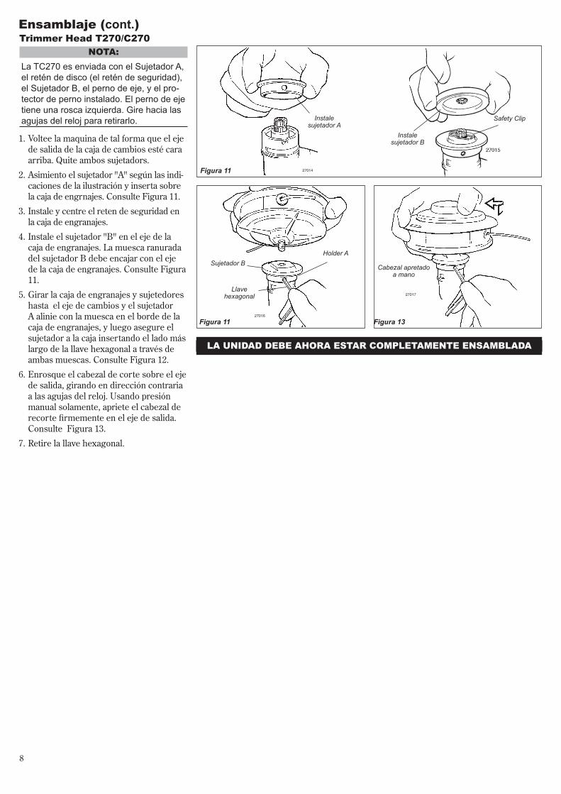
Trimmer head T270/C270NoTA:
LaTC270esenviadaconelSujetadorA,elreténdedisco(elreténdeseguridad),elSujetadorB,elpernodeeje,yelpro-tectordepernoinstalado.Elpernodeejetieneunaroscaizquierda.Girehacialasagujasdelrelojpararetirarlo. Instale
sujetador AInstale
sujetador B
Sujetador BHolder A
Llave hexagonal
Cabezal apretado a mano
Safety Clip
lA uNIDAD DEBE AhoRA ESTAR CoMPlETAMENTE ENSAMBlADA
Figura 11
Figura 11 Figura 13
Ensamblaje (cont.)
Voltee la maquina de tal forma que el eje de salida de la caja de cambios esté cara arriba. Quite ambos sujetadors.
Asimiento el sujetador "A" según las indi-caciones de la ilustración y inserta sobre la caja de engrnajes. Consulte Figura 11.
Instale y centre el reten de seguridad en la caja de engranajes.
Instale el sujetador "B" en el eje de la caja de engranajes. La muesca ranurada del sujetador B debe encajar con el eje de la caja de engranajes. Consulte Figura 11.
Girar la caja de engranajes y sujetedores hasta el eje de cambios y el sujetador A alinie con la muesca en el borde de la caja de engranajes, y luego asegure el sujetador a la caja insertando el lado más largo de la llave hexagonal a través de ambas muescas. Consulte Figura 12.
Enrosque el cabezal de corte sobre el eje de salida, girando en dirección contraria a las agujas del reloj. Usando presión manual solamente, apriete el cabezal de recorte firmemente en el eje de salida. Consulte Figura 13.
Retire la llave hexagonal.
1.
2.
3.
4.
5.
6.
7.

9
27019B
27018
27019
Instalando la Cuchilla C270
Deslice el retén de seguridad
a posición descentrada
Ponga el disco en su lugar
Deslice de regreso el reten de seguridad
Shaft Bolt
Bolt Guard
Holder B
Gear Shaft
Holder A
Llave hexagonal
Figura 14
Ensamblaje (cont.)
Safety Clip
Apriete el ensamblaje(La cuchilla no se muestra por
claridad)
Llave hexagonal
Instale Soporte B
Disco
Llave combinación de bujía/
destornillador
Figura 15
Ponga la C270 de cabeza, de tal forma que el perno del eje de la caja de engranajes este cara arriba y retire el perno del eje, el protector de perno y el soporte B del eje de la caja de engranajes.
1. Alinie la muesca en el Soporte A con la muesca correspondiente en el borde de la caja de engranajes y luego asegure temporalmente el eje de salida inser-tando la llave hexagonal a traves de ambas muescas. Consulte la figura 14.
2. Deslice el reten de seguridad fuera del centro. Consulte la figura 14A.
3. Encaje la cuchilla sobre el reten de segu-ridad y luego centrelo sobre el borde del Soporte A. Consulte la figuras 14B.
NoTA:Cuandoinstaleciertosdiscos,puedaqueseanecesarioretirartemporalmenteelreténdeseguridad.
¡PRECAuCIÓN!Instaleeldiscodetalmaneraquesusuperficie impresa sea visible al oper-adorcuandolaunidadestéenlapos-iciónnormaldeoperación.
¡ADVERTENCIA!Eldiscodebeencajaren
formaplanacontraelbordedelsujeta-dor.LamuescademontajedeldiscodebeestarcentradasobreelpatrónelevadoenelsujetadordediscoA.
¡ADVERTENCIA!NuncaoperelaC270sinelreténdeseguiridadinstalado.
4. Asegure el disco en su lugar centrando el retén de seguridad en el eje de salida. Consulte la figura 14C.
IMPoRTANTE!El reborde en el sujetador B debe rodear completamente el retén de seguridad, y ambos sujetadores deben estar planos con-tra la superficie del disco.
la C2510 debe estar ahora completamente ensamblada.
5. Instale el sujetador B en el eje de salida. Consulte la figura 15. El reborde en el soporte debe cubrir completamente el reten de seguridad, y debe encajar apretadamente contra la cuchilla.
6. Instale el protector de perno y luego el perno de retencion de la cuchilla. Usando la llave de bujia/destornillador combinado, apriete el perno firmemente en direccion contraria a las agujas del reloj.
7. Retire la llave hexagonal.
Figure 14A
Figure 14B Figure 14C
NoTA: LaTC270esenviadaconelSujetadorA,elreténdedisco(elreténdeseguridad),elSujetadorB,elpernodeeje,yelpro-tectordepernoinstalado.Elpernodeejetieneunaroscaizquierda.Girehacialasagujasdelrelojpararetirarlo.

10
Mezcla de Combustible
llenando el Tanque de Combustible
¡PRECAuCIoN!Estemotorestádiseñadosolamenteparafuncionarconunamezclade50:1degasolinasinplomoyaceitedemezclarparamotoresde2tiempos.ISO-L-EGDoJASOFC.Elusodeaceitesdemezclarnoautorizadospuedeconduciraexcesosdedepósitosdecarbón.
¡PRECAuCIoN!n Nuncauseningúncombustibleque
contengamásde10%dealcoholporvolúmen!Algunasgasolinascontienenalcoholcomooxigenante.Combustiblesoxigenadospuedenaumentarlatemperaturadelmotordurantesufuncionamiento.Bajociertascondiciones,combustibleconalcoholpuedereducirlacalidadlubri-cantedealgunosaceitesdemezcla.
n Aceitesgenéricosyalgunosaceitesparamotoresfueradebordapuedaquenoseanparaelusoenmotoresde2tiempos,dealtoren-dimiento,ynodebenserusadosensumotorShindaiwa!
n Use solamente gasolina fresca, limpia y sin plomo, con índice de octanaje de 87 o superior.
n Mezclado con 50:1 combustible con aceite de mezclar para motores de 2 tiempos .
1. Posicione la máquina sobre una super-ficie plana y nivelada.
2. Retire cualquier suciedad o despojos alrededor de la tapa de combustible.
3. Retire la tapa de combustible y llene el tanque con combustible fresco y limpio.
4. Reinstale la tapa de combustible y apriete firmemente.
¡IMPoRTANTE!Mezcle solamente el combustible necesario para uso inmediato! De ser necesario alma-cenar el combustible por más de 30 días, y si no se está usando aceite con esta-bilizador de combustible, entonces el com-bustible debe ser tratado primero con un estabilizador como por ejemplo StaBil™.
Ejemplos de cantidades de mez-cla a proporción de 50:1n 1 galón de gasolina por 2.6 onzas de
aceite de mezcla.n 5 litros de gasolina por 100 ml de aceite
de mezcla.
SIEMPREpareelmotorypermitaqueseenfrieantesdevolverallenareltanque.Evitesobrellenareltanqueylimpiecualquierderramedecombustible.Limpietododerramedecombustibleyalejeelmotorporlomenos10pies(3met-ros)deldepósitodecombustibleantesdevolveraencenderelmotor!
NUNCAcomienceuopereestamáquinasiexisteunapérdidadecombustible.NUNCAenciendauopereestamáquinasielcarburador,líneasdecombustibley/otapadetanqueotanquedecombustibleseencuentrandañados.NUNCAfumeoenciendafuegoscercadelmotorodelcombustible!NUNCA coloque material inflamable cerca delsilenciadordelmotor!NUNCAopereelmotorsinantescompro-barqueelsilenciadoryelguardachispasesténfuncionandoadecuadamente.
¡ADVERTENCIA!DISMINUyA El RIESgo DE INCENDIoS!

11
27025
Choke Control (closed position)
Arranque del Motor
5. Mientras sostiene el tubo exterior firme-mente con una mano, jale despacio la cuerda del arrancador retráctil hasta que sienta resistencia, luego jale rápidamente para arrancar el motor. Consulte Figura 19.
1. Deslice el interruptor hacia la posición ‘I’ (motor encendido). Consulte la figura 16.
2. Posicione la palanca del acelerador en "marcha rápida" como a continuación:
a. Apriete la palanca del acelerador hacia el manubrio en el tubo del eje.
b. Deprima y mantenga el botón de seguro del acelerador.
c. Mientras deprime el botón de seguro del acelerador, libere la palanca del acelerador. Consulte la figura 16.
3. Presione la bombilla de cebado hasta que vea pasar combustible por el tubo de retorno transparente. Consulte la figura 17.
4. Posicione la palanca del cebador en la posición CLOSED (cerrado) si el motor está frío. Consulte la figura 18.
Cerciórese de que el accesorio de
corte esté libre de obstrucciones !
NoTA:Elencendidodelmotorestácontroladoporuninterruptordedosposicionesmon-tadoenelmangodelaceleradorindicado“I”(encendido)y“O”(apagado).
Figura 18
Figura 19
¡IMPoRTANTE!La bombilla de cebado solamente empuja combustible a travéz del carburador. Presion-ando repetidamente la bombilla de cebado no ahogará el motor con combustible.
¡PRECAuCIoN! Nojaleelarrancadorretráctilhastael final de la cuerda. De lo contrario, puededañarelarrancador.
Brushcutters
Throttle Lock Button
Grass TrimmersIGNITION
SWITCH ON
Figura 16
Bombilla de Cebado
Tubo de Retorno
Figura 17
27021
¡ADVERTENCIA!Nuncaarranqueelmotordesdelapos-icióndeoperación.
¡ADVERTENCIA!Elaccesoriodecortepuedeaccion-arsecuandoenciendaelmotor!
Cuando arranca el motor...n Después de que arranque el motor, per-
mita que caliente en marcha mínima por 2 ó 3 minutos antes de usar la máquina.
n Después de que caliente el motor, levante la máquina y asegure el arnés si así está equipada.
n Presionando el gatillo del acelerador hace que el accesorio de corte gire más rápido; liberando el acelerador permite que el accesorio pare de girar. Si el accesorio de corte continúa girando cuando el motor regresa a marcha mínima, la velocidad mínima del carburador debe ser ajustada.
¡IMPoRTANTE!Si el motor falla en arrancar después de varios intentos con la palanca del obturador en posi-cion cerrada , puede que el motor esté ahogado con combustible. Si esto se sospecha, mueva la palanca del cebador a la posición abierta y repetidamente jale el arrancador retráctil para remover el exceso de combustible y para arran-car el motor. Si aún falla en arrancar el motor, consulte el guía diagnóstico de este manual.
6. Cuando arranque el motor, mueva despacio la palanca del obturador a la posición “OPEN” (abierto). Consulte la figura 20. (Si el motor para después del arranque inicial, cierre la palanca del obturador y vuelva arrancar).
Figura 2027027
Choke Control (open position)
Ponga el motor en marcha mínima por dos o tres minutos antes de apagarlo, luego deslice el interruptor de ignición a la posición “O” (motor apagado). Con-sulte la figura 21.
Parada del Motor
Figura 21
7. Al operar el acelerador, automática-mente desengancha la marcha rápida.
Desmalezadora
Interruptor de Encendido (Apagado)
27029
Podadora

12
Ajuste de Marcha Mínima del MotorEl motor debe retornar a marcha mínima cuando la palanca del acelerador es lib-erada. La marcha mínima es ajustable y debe ser suficientemente mínima para permitir que el embrague del motor libere el accesorio de corte.
Ajuste de Marcha Mínima1. Déjelo funcionar en marcha mínima
durante 2 ó 3 minutos hasta que caliente.
2. Si el accesorio de corte gira mientras el motor está en marcha mínima, reduzca la marcha mínima, girando el tornillo de ajuste de marcha mínima en el sentido contrario a las agujas del reloj. Con-sulte la figura 22.
3. Si tiene un tacómetro disponible, la marcha mínima debe ajustarse a 3,000 (±250) RPM (min-1).
¡ADVERTENCIA!ElaccesoriodecorteNUNCAdebegirarenvelocidadesmínimas!
NoTA:Losajustesdemezcladecarburadorpara maquinas anti-emisiones son prefi-jadosenlafábricaynopuedensercam-biadosenelcampo.
27030
Tornillo de marcha mínima
Figura 22
NUNCA opere la unidad sin el protector del accesorio de corte o sin equipo de pro-tección (arnés, interruptor de encendido, el gancho retén del disco, etc.)
¡ADVERTENCIA!Elprotectordelaccesoriodecorteoequipodeprotecciónnogarantizaproteccióncontrarebotes.USTEDSIEMPREDEBEPROTEGERSE!
Verifique La Condición De La UnidadUse solamente repuestos y accesorios autorizados por Shindaiwa en su des-malezadora Shindaiwa. No haga modifi-caciones a la máquina sin la aprobación escrita de Shindaiwa, Inc.SIEMPRE cerciórese de que el acceso-rio de corte esté propiamente instalado y firmemente apretado antes de usar. NUNCA use un accesorio de corte rajado o doblado, reemplácelo con uno util.
SIEMPRE cerciórese de que el cabezal encaje propiamente dentro del soporte. Si un cabezal propiamente instalado vibra, reemplácelo por uno nuevo y pruebe.SIEMPRE pare el motor inmediatamente
y revise en busca de daños si golpea un objeto extraño o si la unidad se enreda. No opere con equipo dañado o quebrado.NUNCA permita que el motor funcione a altas revoluciones sin carga. De lo con-trario, podría dañar el motor.NUNCA use la máquina con sujetadores o soportes de accesorios desgastados o dañados.NUNCA corte con cuchillas desafiladas. De lo contrario, aumentaria el riesgo de rebote de la cuchilla y también puede cau-sar da?o a su equipo.

13
Sostenga la má-quina de tal forma que el cabezal esté en ángulo al área de corte. Para obtener máxima vida útil del cable de nylon, corte
solamente con la punta del cable. Corte césped moviendo el cabezal de izquierda a derecha. Mantenga el cabezal horizontal-mente. Consulte la figura 25.
orillasIncline el mango más o menos a 100º hacia la izquierda (desde la posición horizontal) y avance hacia adelante, sosteniendo la recortado-ra verticalmente como se muestra en la figura 26.
Arnés
Shoulder Strap recommended
for use with grass trimmers
NoTA:Apesardequeelarnésnoesrequeridaconelusodepodadoras,unarnéspuedeaumentarlacomodiadparaeloperadorduranteperiodosextensosdeoperación.
¡ADVERTENCIA!Siempreuseunarnéscuandoopereestaunidadconunacuchilla.Unarnésestambiénrecomendadocuandousecabledenylon.
¡IMPoRTANTE!Ajuste el arnés de tal forma que la almohad-illa descanse cómodamente sobre los lados de los hombros y que la trayectoria de corte del accesorio de corte esté paralelo al suelo. Asegure que todo los ganchos y dispositivos de ajuste estén asegurados.
C270/T270 con una Cuchilla
T270 con un Cabezal de Nylon
27032AFigura 23
Figura 24
27033
27034
Corte de Césped – Máquinas Equipadas con Cabezal de NylonSu podadora Shindaiwa T270 pueda que esté equipada con uno de varios modelos de cabezales de corte de Shindaiwa, cada uno con caracte-rísticas para aplicaciones específicas y/o requisitos operacionales.
NoTA:Un cabezal de nylon tambien puede ser insta-lado en la desmalezadora C270 Shindaiwa. Para la operación adecuada, consulte siempre las instrucciones incluídas en el cabezal de corte. Entre los modelos de cabezales de corte disponibles se incluyen:
n Semi-Automático: La línea de corte es indexada cuando el operario toca el suelo con el cabezal de corte durante el uso.
n Manual: El operario suelta manual-mente el cable con la podadora comple-tamente detenida.
n Fijo: El operario debe apagar el motor y añadir manualmente nuevos pedazos de línea de corte.
n Pivote: Este dispositivo, diseñado para cortar mala hierba o maleza ligera, in-cluye tres cuchillas de nilón atornilladas al cabezal a travéz de pivotes.
¡PRECAuCIoN!Nopresioneelcabledenyloncontraárboles,cercasdealambreocualquierotromaterialquepuedaatascaroromperelcable.
Velocidades de operación del MotorOpere la máquina a aceleración máxima cuando corte césped.
¡PRECAuCIoN!Operelamáquinaaaceleraciónmáximacuandocortecésped.
Recorte y Podado de Césped
Figura 25
Figura 26

14
27036
¡ADVERTENCIA!Alefectuarcortesverticales,nuncapermitaqueeldiscosobrepaselaalturadesucintura.
¡ADVERTENCIA!n Cuandocortemaderaconundisco,
presioneeldiscolentamente.Nunca golpee un disco en rotación contra la madera.
n Nousediscosdecortede2dientesodiscosdecortede4dientesnoaprobadosporShindaiwaensudes-malezadoraopodadoraShindaiwa.
El disco gira en dirección contraria a las agujas del reloj. Para máximo rendimiento y para reducir el ser golpeado por despo-jos, mueva el disco de derecha a izquierda mientras avanza en su trabajo. Ubique el disco de tal manera que los cortes se reali-zen entre las 7 horas y las 11 horas (agujas de un reloj). NO CORTE entre las 11 horas y 5 horas. Consulte la figura 27.
Corte en el lado izquierdo del disco. MANTENGA
SU CUERPO FUERA DE LA TRAYECTORIA DEL
DISCO!
Sostenga la desmalezadora con el disco a un ángulo de 90 grados con respecto al suelo, de forma que el borde inferior del disco gire hacia el operario. Mueva el disco de arriba para abajo a travéz del corte, y corte solamente con el borde infe-rior del disco. Consulte la figura 28.
Figura 28
Cortes Verticales
Rebote de DiscoEl rebote de disco es un movimiento repentino de lado a lado o hacia atrás de la desmalezadora. Tal movimiento puede ocurrir cuando el disco se enreda o gol-pea un objeto tal como ramas o troncos de árbol. ESTÉ CONSTANTEMENTE ALERTA DEL REBOTE DE DISCO Y PROTEJASE CONTRA SUS EFECTOS !
Mango tipo bicicleta para desmalezadoraEl mango tipo bicicleta para desmalezadora ayuda a prevenir que el operario se mueva hacia adelante o que la unidad se mueva hacia atrás, impidiendo así el contacto del cuerpo con el accesorio de corte. SIEM-PRE MANTENGA EL MANGO ASEGU-RADO EN SU SITIO EN LA UNIDAD !
Arnés para DesmalezadorasUn arnés provee protección adicional en contra de rebotes de cuchilla. Además, un arnés da un significante soporte y comodi-dad para ayudar a asegurar una operación segura y eficiente.
Cuando use una desmalezadora, cerciorese que el mango y el árnes estén ajustados a la talla del operador que usa la unidad.
usando un disco C270
¡ADVERTENCIA!n Antesdetrabajarconunaunidad
equipadaconundisco,inspec-cionesiempreylimpielosobjetoseneláreaquepuedaninterferirodañareldisco.
n NUNCAuseundiscocercadeveredas, cercas, edificios u otros objetosquepuedancausarlesio-nesodaños.
n NUNCAuseundiscoparaningúnotropropósitoapartedelcualhasidodiseñado.
n Cuandogolpeeunobjetosólidoconundisco,siemprepareelmotorycuidadosamenteinspec-cioneeldiscoenbuscadedaños.NUNCAOPERELADESMALEZA-DORACONUNDISCODAÑADO!
n Unaunidadequipadaconundiscodebeestarequipadaconunmangotipobicicleta,asítambiéncomoconunárnes.
n SIEMPREcerciorequeelprotec-tordelaccesoriodecorteestépropiamenteinstaladoantesdeoperarlaunidad.
Velocidades de operación del MotorOpere el motor a máxima potencia mien-tras corte. Para mayor eficiencia de combustible, suelte el acelerador cuando voltee de regreso después de un corte.
n Para evitar posibles daños al motor, no permita que la desmalezadora funcione a altas velocidades sin carga.
n Evite operar el accesorio a velocidades bajas. De lo contrario, puede conducir a un desgaste rápido del embrague. Adi-cionalmente, la operación a baja velo-cidad tiende a hacer que el cabezal de corte se enrede con césped y despojos.
Figura 27
No CoRTE
10 horas
Proceda a cortar
5 horas
Rotación del disco
8 horas

15
Mantenimiento Diario
27037
Antes de cada día de trabajo, efectúe lo siguiente:
Retire y limpie o reemplace el
elemento
Mantenimiento Cada 10 horas
Cada 10 horas de operación (más frecuentemente bajo condiciones sucias o polvorientas):
n Retire el elemento del filtro de aire. Con-sulte la figura 29. Limpie o reemplace como sea necesario. Para lavar el elemento: Lavelo meticulosamente con agua y jabón. Deje que seque antes de reinstalarlo.
¡PRECAuCIoN!No opere esta máquina si el filtro de aire estásucio,dañadoosiestáhúmedo.
Figura 29
n Revise que no falten tornillos y que no estén flojos. Cerciórese de que el accesorio de corte esté firmemente asegurado.
n Revise la máquina entera en busca de goteo de combustible o grasa.
Mantenimiento
¡ADVERTENCIA!Losrepuestosnooriginalespuedencausardañoyconduciraunalesión
SilenciadorEsta máquina nunca debe ser operada con un guardachispas o silenciador defectuoso o faltante. Cerciórese de que el silenciador esté bien asegurado y en buena condición. Un silenciador usado o dañado es un riesgo de incendio y puede causar la per-dida de audición.
Bujía Mantenga la bujía y las conexiones de cable apretadas y limpias.
SujetadoresCerciórese de que las tuercas, pernos y tornillos (a excepción de los tornillos de ajuste del carburador) estén apretados.
¡ADVERTENCIA!n Nuncarepareundiscodañadosol-
dándolo, enderezándolo o modifi-candosuforma.Unavezalterado,podríaquebrarseenplenaoperaciónyocasionarlesionespersonalesserias.
n Nousediscosdecortede2o4dientesnoaprobadosporShindaiwaensudesmalezadoraopodadoraShindaiwa.
n Losdiscosdecortenosoninter-cambiablesentrelasorilladorasodesmalezadoras.Elusodecualquieraunidadcondiscosoaccesoriosnoaprobadosparalarespectivaunidadpuedenserpelig-rososyocasionarlesionesgraves.
¡ADVERTENCIA!Antesdeefectuarmantenimiento,reparaciónolimpiezadelamáquina,cercióresedequeelmotoryelacceso-riodecorteesténcompletamentedeteni-dos.Desconecteelcabledebujíaantesdeefectuarserviciodemantenimiento.
¡IMPoRTANTE!EL MANTENIMIENTO, REEMPLAZO O REPARACION DE LOS SISTEMAS Y DISPOSITIVOS DE CONTROL DE EMIS-ION PUEDEN SER EFECTUADOS POR CUALQUIER ESTABLECIMIENTO O INDIVIDUO; SIN EMBARGO, LAS REPA-RACIONES DE GARANTIA DEBEN SER EFECTUADAS POR SU CENTRO DE SER-VICIO O DISTRIBUIDOR AUTORIZADO POR SHINDAIWA CORPORATION. EL USO DE PARTES QUE NO SON EQUIVA-LENTES EN RENDIMIENTO Y DURABI-LIDAD A LAS PARTES AUTORIZADAS PUEDEN AFECTAR LA EFECTIVIDAD DE SU SISTEMA DE CONTROL DE EMISION Y PUEDE INFLUENCIAR EL RESULTADO DE SU RECLAMO DE GARANTIA.
NoTA:El usar repuestos no estándar podría inval-idar su garantía Shindaiwa.
CuchillasMantenga los discos afilados y revise la condición del disco frecuentemente. Si el rendimiento de un disco cam-bia repentinamente, pare el motor y revise el disco en busca de rajaduras u otro daño. Reemplace el disco dañado IMMEDIATAMENTE!
n Retire toda suciedad y despojo del motor, revise las aletas de enfríamiento y el filtro de aire y límpielos de ser necesario.
n Cuidadosamente, retire cualquier acumu-lación de suciedad o despojo del silencia-dor y del tanque de combustible. La acu-mulación de suciedad en dichas áreas puede ocasionar el sobrecalentamiento del motor, inducir el gasto prematuro o crear un riesgo de incendio.

16
27040
27031
Gancho de
Alambre
10/15-hour MaintenanceCada 10 ó 15 horas de operación:
n Retire y limpie la bujía. Ajuste la distan-cia del electrodo a 0.024-0.028 pulgadas (0.6 -0.7 mm). Si la bujía necesita ser reemplazada, use solamente una bujía BPMR6A o una bujía equivalente con resistencia al calor correcta..
¡PRECAuCIoN!Beforeremovingthesparkplug,cleantheareaaroundtheplugtopreventdirtanddustfromgettingintotheinternalengineparts
Limpie la bujía y revise la distancia del electrodo.
27038
0.024" (0.6 mm)
Champion CJ8Y
Figura 30
Mantenimiento Cada 50 horasCada 50 horas de operación (más frecuentemente bajo condiciones sucias o polvorientas):n Retire y limpie la tapa del cilindro y
limpie la maleza y la suciedad en las ale-tas del cilindro.
n Retire el accesorio de corte, el soporte del accesorio de corte y el collar de la caja de engranajes. Retire la tuerca del alimentador del costado de la caja de engranajes e introduzca grasa nueva a la caja hasta que la grasa usada salga. Use solamente grasa a base de litio, tal como grasa Shindaiwa para Caja de Engranajes o su equivalente. Consulte la figura 31.
27039
Grasa Nueva Grasa Usada
Caja de engranajes
n Use un gancho de alambre para extraer el filtro de combustible del tanque de combustible. Consulte la figura 30. Retire y reemplace el filtro. Antes de reinstalar el filtro, inspeccione la condición de la tubería de combustible. Si descubre daños o deteriorización, retire la unidad de operación hasta que pueda ser inspeccionada o reparada por un técnico de servicio entrenado por Shindaiwa. Consulte Figura 32.
Figura 31
Figura 32
¡PRECAuCIoN!Aseguredenoperforarlatuberíadecombustibleconlapuntadelganchodealambre,puesestalíneaesdelicadaysepuededañarfácilmente.
Los depósitos de carbón en la rejilla del guardachispas del silenciador pueden cau-sar dificultades en el encendido o pérdida de potencia al motor.
En estos casos, para restaurar la potencia retire y limpie la rejilla guardachispas con un cepillo de cerdas de alambre. Después de limpiar instale la rejilla guardachispas en el silenciador.
En caso de haber depósitos abundantes de carbón o si el rendimiento no mejora después de limpiar la rejilla del guar-dachispas, consulte a su distribuidor Shindaiwa más cercano.
¡ADVERTENCIA!Nuncaoperelamáquinaconunsilen-ciadoroguardachispasdañadoofalt-ante!Delocontrario,puedeserunriesgodeincendioypodríatambiéncausardañosasusoidos.
Silenciador
Tornillo
Guardachispas
Maintenimiento de silenciador
Figura 33
Mantenimiento (cont.)

17
Almacenamiento de largo PlazoCada vez que la máquina no va a ser usada por 30 días o más, siga los siguientes procedimientos para preparar su almacenamiento:
n Limpie las partes externas minuciosamente.
n Drene todo combustible en el tanque.
¡IMPoRTANTE!Todo combustible almacenado debe estar estabilizado con un estabilizador de com-bustible tal como STA-BIL™, al menos que use aceite con estabilizador de combustible.
Para retirar el resto del combustible en las tuberías de combustible y carburador y con el tanque de combustible vacío.
1. Presione la bombilla de cebado hasta que el combustible deje de pasar.
2. Arranque y mantenga encendido el motor hasta que pare de funcionar.
3. Repita los pasos 1 y 2 hasta que el motor ya no arranque.
n Retire la bujía y vierta aproximada-mente 1/4 de onza de aceite de mezcla para motores de 2 tiempos en el cilindro a travéz del agujero de la bujía. Lenta-mente jale el arrancador 2 ó 3 veces para que el aceite se aplique uniforme-mente en el interior del motor. Reinstale la bujía.
n Antes de almacenar la máquina, repare o cambie cualquier pieza dañada o gastada.
n Retire el elemento del filtro de aire del carburador y límpielo minuciosamente con agua y jabón. Deje que seque y vuelva a ensamblar el elemento.
n Almacene la máquina en un sitio limpio y libre de polvo.
¡PRECAuCIoN!Gasolinaalmacenadaenelcarbura-dorporperíodoslargospuedecausarunarranqueduroypuedeconduciraunaumentoencostodeservicioymantenimiento.
27042
300
27041
Cuando los bordes de corte de un disco pierdan su filo, pueden ser afilados rápi-damente con una lima. Para mantener el disco balanceado, todos los bordes de corte deben ser afilados uniformemente.
Lima Redonda
Dirección de Afilado
Afilado de Discos
Disco Shindaiwa Tornado™TPara afilar los dientes de corte de un disco shindaiwa Tornado ™, use una lima redonda de 7/32 pulgadas. Afile el borde guía de cada diente hasta obtener un filo similar al de una hoja de afeitar. La super-ficie superior de cada diente debe tener una inclinación de 30 grados. Consulte la Figura 34.
¡ADVERTENCIA!Afile solamente los dientes de cortar. NOalteredeningunaformaelcon-tornodeldisco.
Discos de Dientes MúltiplesUse una lima redonda para mantener un radio de 0.04 a 0.06 pulgadas (1 a 1.5mm) en la base de cada diente. Los dientes deben quedar igualmente descentrados por cada lado. Consulte la figura 35.
Lima Redonda
Filing Direction
Figura 34
Figura 35

18
El Motor No Arranca
¿Arranca el motor?
Arrancador defectuoso. Liquido en el cárter.Daños internos
Consulte con su agente de servicio autorizado.
Consulte con su agente de servicio autorizado.
Consulte con su agente de servicio autorizado.
No
¿Buena compresión?
Bujía floja. Desgaste en el cilindro, pistón, anillos.
Ajuste y pruebe otra vez.No
SI
¿Contiene el tanque combustible fresco y del octanaje correcto?
Vuelva a llenar con combustible fresco, limpio y sin plomo con un octanaje de 87 o superior mezclado con aceite de mezcla para motores de 2 tiempos Shindaiwa enfriado por aire que cumple o excede los aceites clasificados ISO-L-EGD y/o JASO FC a una proporción de 50:1 de gasolina/aceite.
Combustible incorrecto, viejo, o contaminado; mezcla incorrecta.
No
SI
¿Se ve el combustible circular por la línea de retorno al realizar el cebado?
Revise el filtro de combustible y/o el ventilador en busca de obstrucción.
Limpie como sea requerido; vuelva a arrancar.No
¿Hay chispa en el terminal del cable de bujía?
El interruptor de encendido está en posición “O” (OFF) (apagado).
Corto circuito en la conexión a tierra. Sistema de encendido o ignición defectuoso.
Mueva el interruptor a la posición de encendido (I) y vuelva arrancar. No
SI
SI
Revise la bujía.
Si la bujía está húmeda, puede haber exceso de combustible en el cilindro.
La bujía está obstruída o tiene la distancia incorrecta.
La bujía está dañada internamente o es el tamaño equivocado.
Retire la bujía y arranque el motor; reinstale la bujía y vuelva arrancar.
Limpie y calibre la bujía a 0.024 pulgadas (0.6 mm). Vuelva arrancar.
Reemplace la bujía por una Champion CJ8 o una equivalente con resistencia al calor correcta. Ajuste la holgura del electrodo de la bujia a 0.024 pulgadas (0.6 mm).
SI
Posible CausaQue Revisar Remedio
Guía Diagnóstico

19
BAJA PoTENCIA
¿Se está sobrecalentando el motor?
El operador esta sobre trabajando la máquina.
La mezcla del carburador es muy pobre.
Proporción de combustible inapropiada.
Ventilador, tapa del ventilador, aletas del cilindro están sucios o dañados.
Depósitos de carbón en el pistón o en el silenciador.
Recorte el cable de nylon. Corte más despacio.
Consulte con su agente de servicio autorizado.
Vuelva a llenar con combustible fresco, limpio y sin plomo con un octanaje de 87 o superior mezclado con aceite de mezcla para motores de 2 tiempos Shindaiwa enfriado por aire que cumple o excede los aceites clasificados ISO-L-EGD y/o JASO FC a una proporción de 50:1 de gasolina/aceite.
Limpie, repare o reemplace como sea necesario.
Consulte con su agente de servicio autorizado.
QueRevisar PosibleCausa Remedio
El motor funciona bruscamente en cualquier velocidad. Puede tener humo negro y/o combustible sin usar en el escape.
Filtro de aire obstruído.
Bujía floja o dañada.
Fuga de aire o línea de combustible obstruída.
Agua en el combustible.
Pistón trabado.
Carburador defectuoso y/o diafragma.
Limpie el elemento de aire.
Apriete o reemplace la bujía por una Champion CJ8 o una equivalente con resistencia al calor correcta. Ajuste la holgura del electrodo de la bujia a 0.024 pulgadas (0.6 mm)
Repare o cambie el filtro y/o la manguera de combustible.
Vuelva a llenar con combustible fresco, limpio y sin plomo con un octanaje de 87 o superior mezclado con aceite de mezcla para motores de 2 tiempos Shindaiwa enfriado por aire que cumple o excede los aceites clasificados ISO-L-EGD y/o JASO FC a una proporción de 50:1 de gasolina/aceite.
Consulte con su agente de servicio autorizado.
Consulte con su agente de servicio autorizado.
El motor está golpeando.
Sobrecalentamiento
Combustible inadecuado
Depósitos de carbón en la cámara de combustión.
Consulte arriba.
Revise el índice de octanaje del combustible. Revise si hay alcohol en el combustible. Vuelva a llenar si es necesario. (Consulte página 9).
Consulte con su agente de servicio autorizado.
Guía Diagnóstico (continuación)

20
PROBLEMAS ADICIONALES
Aceleración deficiente.
Filtro de aire obstruído.
Filtro de combustible obstruído.
La mezcla del carburador es muy pobre. Marcha mínima ajustada muy baja.
Limpie el elemento de aire.
Cambie el filtro de combustible
Consulte con su agente de servicio autorizado
Ajuste: a 3,000 RPM (+ 250) rpm (min-1)
Symtoma PosibleCausa Remedio
El motor se apaga abruptamente
El interruptor está en la posición de apagado.
El tanque de combustible está vacío.
Filtro de combustible obstruído.
Agua en el combustible.
Bujía defectuosa o terminal flojo.
Falla en el sistema de encendido.
Pistón trabado.
Fije el interruptor y vuelva arrancar.
Vuelva a llenar.
Cambie el filtro de combustible.
Vuelva a llenar con combustible fresco, limpio y sin plomo con un octanaje de 87 o superior mezclado con aceite de mezcla para motores de 2 tiempos Shindaiwa enfriado por aire que cumple o excede los aceites clasificados ISO-L-EGD y/o JASO FC a una proporción de 50:1 de gasolina/aceite.
Limpie y cambie la bujía; Apriete el terminal.
Consulte con su agente de servicio autorizado.
Consulte con su agente de servicio autorizado.
Se hace difícil apagar el motor.
La conexión a tierra está desconectada, o el interruptor está defectuoso.
Sobrecalentamiento debido a bujía incorrecta
Motor sobrecalentado.
Pruebe y reemplace como sea requerido.
Reemplace la bujía por una Champion CJ8 o una equivalente con resistencia al calor correcta. Ajuste la holgura del electrodo de la bujia a 0.024 pulgadas (0.6 mm)
Marcha mínima hasta que enfríe. Consulte la página 10 (motor sobre calentado)
El accesorio de corte gira con el motor en marcha mínima.
Marcha mínima ajustada muy alta.
Resorte del embrague está quebrado o el resorte del embrague está gastado.
Fije la marcha mínima: 3,000 (250) rpm (min-1).
Cambie los resortes/zapatas como sea necesario, revise la marcha mínima.
Vibración excesiva.
El accesorio está dañado o doblado. Acoplador suelto.
El eje principal está doblado o los bujes están dañados o gastados.
Inspeccione o reemplace como sea necesario.
Apriete el acoplador seguramente. Inspeccione o reemplace como sea necesario.
Guía Diagnóstico (continuación)

21
Shindaiwa Corporation garantiza al comprador inicial y a cada propietario siguiente, que este motor para equipos de uso general (de aquí en adelante motor) está diseñado, fabricado y equipado para cumplir, en el momento de la venta inicial, con todas los reglamentos vigentes de la Administración de Protección Ambiental de EE.UU. (EPA) y que no tiene defectos materiales ni de mano de obra que pudieran hacer que el motor no cumpla con las reglamentaciones de la EPA durante el período de vigencia de la garantía. Esta garantía sobre normas de emisión rige para todos los estados, excepto para el Estado de California. Para las piezas listadas en PIEZAS CUBIERTAS, el Distribuidor autorizado por Shindaiwa Corporation efectuará, sin costo para el propietario, los diagnósticos, reparaciones o reemplazos necesarios de cualquier componente defectuoso en relación con las emisiones para asegurar que el motor cumpla con las reglamentaciones de la EPA de EE.UU. aplicables.
CoBERTURA DE lA gARANTÍA DEl FABRICANTE Cuando este equipo se vende en EE.UU., el sistema de control de emisiones del mismo está garantizado por un período de 2 (dos) años a partir de la fecha en que el producto haya sido entregado por primera vez al comprador minorista original.
RESPoNSABIlIDADES DEl PRoPIETARIo RESPECTo DE lA gARANTÍA Como propietario del motor, usted es responsable de la realización del mantenimiento requerido listado en su manual del propietario. Shindaiwa Corporation le recomienda conservar todos los comprobantes que cubran el mantenimiento de su motor, pero Shindaiwa Corporation no puede negar una reclamación de garantía exclusivamente debido a la falta de comprobantes o porque usted no pueda asegurar la realización de todos los mantenimientos programados. Como propietario del motor, usted deberá sin embargo estar enterado de que Shindaiwa Corporation podrá negarle cobertura de garantía si el motor o alguna pieza ha fallado debido a uso abusivo, negligencia, mantenimiento inadecuado o modificaciones no autorizadas. Usted es responsable de la presentación del motor al distribuidor autorizado de Shindaiwa Corporation más cercano cuando exista algún problema. Si el distribuidor Shindaiwa no puede responder su pregunta con respecto a sus derechos y responsabilidades de garantía, deberá entonces comunicarse con su distribuidor regional de Shindaiwa. Para obtener el nombre y el número telefónico del distribuidor de Shindaiwa en su localidad, comuníquese con Shindaiwa Inc., al (503) 692-3070 de 8:00 a.m. a 5:00 p.m., hora del Pacífico.
PIEZAS CUBIERTAS A continuación se listan las piezas cubiertas por la garantía de diseño federal de emisiones y defectos. Algunas partes mencionadas a continuación pueden requerir mantenimiento periódico y están garantizadas hasta el primer reemplazo programado de las mismas. Las partes garantizadas incluyen:1. Componentes internos del carburador • Armado y medición del chorro y el diafragma2. Componentes del sistema de encendido • Bobina de encendido • Rotor del volante El sistema de control de emisiones del motor Shindaiwa puede también incluir ciertas mangueras y conexiones afines.
lIMITACIoNES La garantía por diseño federal de emisiones y defectos no cubrirá nada de lo siguiente:
(a) Condiciones que resulten de una intervención no autorizada, un mal uso, un ajuste inapropiado (a menos de que los hubieran efectuado un distribuidor o un centro de servicio autorizado de Shindaiwa Corporation, en el curso de una reparación de garantía), una alteración, accidente, omisión en el uso del combustible y aceite recomendados o de una omisión en el cumplimiento de los servicios de mantenimiento requeridos,
(b) Los repuestos usados para los servicios de mantenimiento requeridos, (c) Partes consecuenciales utilizadas para efectuar los servicios de
mantenimiento requeridos, (d) Cuotas de diagnóstico e inspección que no resulten en servicios
cubiertos por la garantía, (e) Todo repuesto no autorizado o la falla de partes autorizadas que
Shindaiwa CorporationGarantía limitada de defectos y diseño de emisiones federales
Motores de uso general y para parques y jardines
pudieran deberse al uso de partes no autorizadas.
REQUISIToS DE MANTENIMIENTo y REPARACIÓN Usted es responsable del uso y mantenimiento correctos del motor. Usted deberá conservar todos los comprobantes y registros de mantenimiento que cubran la realización de mantenimiento regular en caso de que surjan preguntas. Estos comprobantes y los registros de mantenimiento deberán ser transferidos a cada propietario subsiguiente del motor. Shindaiwa Corporation se reserva el derecho a negar la cobertura de garantía si el propietario no ha mantenido correctamente el motor. Shindaiwa Corporation, sin embargo, no negará reparaciones bajo garantía por el solo hecho de no haberse efectuado reparaciones o mantenimiento o por la omisión de mantener registros de mantenimiento.EL MANTENIMIENTO, REEMPLAZO O REPARACIÓN DE DISPOSITIVOS Y SISTEMAS DE CONTROL DE EMISIONES PUEDE SER REALIZADO POR CUALQUIER ESTABLECIMIENTO O PERSONA DEDICADOS A ELLO; SIN EMBARGO, LAS REPARACIONES CUBIERTAS POR LA GARANTÍA DEBEN SER LLEVADAS A CABO POR UN DISTRIBUIDOR O CENTRO DE SERVICIO AUTORIZADO POR SHINDAIWA CORPORATION EL EMPLEO DE PIEZAS QUE NO SON EQUIVALENTES EN RENDIMIENTO Y DURABILIDAD A LAS PIEZAS AUTORIZADAS PUEDE REDUCIR LA EFECTIVIDAD DEL SISTEMA DE CONTROL DE EMISIONES Y PUEDE AFECTAR EL RESULTADO DE UNA RECLAMACIÓN DE GARANTÍA. Si se utilizaran piezas no autorizadas por Shindaiwa Corporation para reemplazos por mantenimiento o reparación de componentes que afecte el control de emisiones, se deberá asegurar que dichas piezas estén garantizadas por el fabricante como equivalentes a las piezas autorizadas por Shindaiwa Corporation en lo relativo al rendimiento y durabilidad.
SolICITUDES DE SERVICIo DE gARANTÍA Toda reparación realizada conforme a los términos de esta garantía limitada deberá ser llevada a cabo por un distribuidor autorizado por Shindaiwa Corporation. Si cualquier pieza vinculada con las emisiones es encontrada defectuosa durante el período de garantía, es su responsabilidad presentar el producto a un distribuidor autorizado de Shindaiwa. Presente sus comprobantes de venta en los que aparezca la fecha de compra del motor. El distribuidor autorizado de Shindaiwa Corporation llevará a cabo las reparaciones o ajustes necesarios en un lapso razonable, suministrándole una copia de dicha orden de reparación. Todas las piezas y accesorios reemplazados bajo esta garantía pasarán a ser propiedad de Shindaiwa Corporation. Para localizar a un agente de servicio Shindaiwa más cercano a usted, favor de ponerse en contacto con su distribuidor Shindaiwa. Para obtener el nombre y el número telefónico del distribuidor de Shindaiwa en su localidad, comuníquese con Shindaiwa Inc., al (503) 692-3070 de 8:00 a.m. a 5:00 p.m., hora del Pacífico.
ESTA gARANTÍA ES ADMINISTRADA PoR: Shindaiwa Inc.11975 S.W. Herman Rd.Tualatin OR 97062(503) 692-3070

22
NoTAS:
Shindaiwa Inc.11975 S.W. Herman Rd.Tualatin, Oregon 97062 USATelephono: 503 692-3070Fax: 503 692-6696www.shindaiwa.com
Shindaiwa CorporationHead Office: 6-2-11, Ozuka-NishiAsaminami-Ku, Hiroshima731-3167, JapanTelephono: 81-82-849-2220Fax: 81-82-849-2481
©2008 Shindaiwa, Inc. Numero de part 62057-94310Revisado 1/08Shindaiwa es una marca registrada de Shindaiwa, Inc.Especificaciones sujetas a cambio sin previo aviso..