Embed Size (px)
Citation preview
SHIMADZU LC-10/20SYSTEM
Clarity Control Module ENG
Code/Rev.: M108/70CDate: 10/2/2017
Phone: +420251013400 DataApex Ltd.
Fax: +420251013401 Petrzilkova 2583/13
[email protected] 15800Prague 5
www.dataapex.com TheCzech Republic

Clarity® , DataApex® and ® are trademarks of DataApex Ltd. Microsoft ® and WindowsTM aretrademarks of Microsoft Corporation.DataApex reserves the right to make changes to manuals without prior notice. Updated manuals can bedownloaded fromwww.dataapex.com.
Author: DM
Shimadzu LC-10/20 System Table of Contents
Contents1 Shimadzu LC-10/20 System 12 Requirements 32.1 Minimal version of device firmware required 4
3 Installation Procedure 53.1 Shimadzu LC-10/20 System communication 53.2 Software Installation 73.3 Clarity Configuration 83.4 Shimadzu LC-10/20 System Setup 113.4.1 Shimadzu LC-10/20 System Setup - Setup 123.4.2 Shimadzu LC-10/20 System Setup - Controller 14
4 Using the control module 164.1 Pump 174.1.1 Shimadzu LC-10/20 System Setup - Pump 174.1.2 Method Setup - LC Gradient 194.1.2.1 Gradient Options 21
4.1.3 Method Setup - LC 234.1.4 Method Setup - Advanced 264.1.5 Device Monitor 274.1.6 Report Setup 29
4.2 Detector 304.2.1 Shimadzu LC-10/20 System Setup - Detector 304.2.2 Method Setup - Acquisition - Detector 324.2.2.1 Method Setup - Acquisition - RF Detector 344.2.2.2 Method Setup - Acquisition - RID Detector 36
4.2.3 Method Setup - Acquisition - Time Program 384.2.4 Method Setup - Acquisition - Analog Output 404.2.5 Device Monitor 414.2.6 Report Setup 43
4.3 Autosampler 454.3.1 Shimadzu LC-10/20 System Setup - Autosampler 454.3.2 Method Setup - AS - Sampler 474.3.2.1 Method Setup - AS - Sampler (SIL-10Axl) 494.3.2.2 Method Setup - AS - Sampler (SIL-10AF) 50
4.3.3 Method Setup - AS - Time Program 514.3.4 Method Setup - AS - Pretreatment 524.3.5 Device Monitor - Shimadzu LC-10/20 System 564.3.6 Report Setup 57
4.4 PDA 584.4.1 Shimadzu LC-10/20 System Setup - PDA Detector 584.4.2 Method Setup - PDA 604.4.3 Method Setup - Acquisition 624.4.4 Device Monitor 634.4.5 Report Setup 64
4.5 Thermostat 65
- i -

Table of Contents ClarityControlModule
4.5.1 Shimadzu LC-10/20 System Setup - Thermostat 654.5.2 Method Setup - Thermostat - Thermostat 664.5.3 Method Setup - Thermostat - Time Program 674.5.4 Device Monitor 684.5.5 Report Setup 69
5 Troubleshooting 706 Vial Plate Numbers 71
- ii -
Shimadzu LC-10/20 System Table of Contents
To facilitate the orientation in the Shimadzu LC- 10/20 System manual and Claritychromatography station, different fonts are used throughout the manual. Meanings of these fontsare:
Instrument (blue text) marks the nameof thewindow to which the text refers.Open File (italics) describes the commands and names of fields in Clarity, parameters that canbe entered into themor a window or dialog name (when you already are in the topic describingthewindow).WORK1 (capitals) indicates the nameof the file and/or directory.ACTIVE (capital italics) marks the state of the station or its part.
The bold text is sometimes also used for important parts of the text and the name of the Claritystation. Moreover, some sections are written in format other than normal text. These sections areformatted as follows:
Note: Notifies the reader of relevant information.
Caution: Warns the user of possibly dangerous or very importantinformation.
▌ Marks the problem statement or trouble question.Description: Presents more detailed information on the problem, describes its causes,
etc.Solution: Marks the response to the question, presents a procedure how to remove it.
- iii -

Shimadzu LC-10/20 System 1 Shimadzu LC-10/20 System
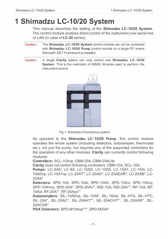
1 Shimadzu LC-10/20 SystemThis manual describes the setting of the Shimadzu LC-10/20 System .The control module enables direct control of the instrument over serial lineor LAN (in case of LC-20 series).
Caution: The Shimadzu LC-10/20 System control module can not be combinedwith Shimadzu LC-10/20 Pump control module on a single PC whereMicrosoft .NET Framework is installed.
Caution: A single Clarity station can only control one Shimadzu LC- 10/20System. This is the restriction of MIMIC libraries used to perform theinstrument control.
Fig 1: Shimadzu Prominence system
As opposed to the Shimadzu LC- 10/20 Pump , this control moduleoperates the whole system (including detectors, autosampler, thermostatetc.), not just the pump, but requires any of the supported controllers forthe operation of any other modules. Clarity can currently control followingmodules:Controllers: SCL-10Avp, CBM-20A, CBM-20ALiteClarity does not control following controllers: CBM-10A, SCL-10A.Pumps: LC-6AD, LC-8A, LC-10AD, LC-10AS, LC-10AT, LC-10Ai, LC-10ADvp, LC-10ATvp, LC-20AT*, LC-20AD*, LC-20ADXR*, LC-20AB*, LC-20AS*Detectors: SPD-10A, SPD-10Ai, SPD-10AV, SPD-10Avi, SPD-10Avp,SPD-10AVvp, SPD-20A*, SPD-20AV*, RID-10A, RID-20A**, RF-10A, RF-10Axl, RF-20A**, RF-20Axs**Autosamplers: SIL-10ADvp, SIL-10AF, SIL-10Axl, SIL-HTA, SIL-HTC,SIL- 20A*, SIL- 20AC*, SIL- 20AHT*°, SIL- 20ACHT*°, SIL- 20AXR*, SIL-20ACXR*PDA Detectors: SPD-M10Avp***, SPD-M20A*
- 1 -
1 Shimadzu LC-10/20 System ClarityControlModule
Thermostats: CTO-10A, CTO-10AC, CTO-10Avp, CTO-10ACvp, CTO-10ASvp, CTO-20A*, CTO-20AC*The list continues to extend, for up to date list see the websitewww.dataapex.com. Some devices also require a firmware of particularminimal version for proper communication with Clarity (for more detailssee the chapter Minimal version of device firmware required on pg 4).* Devices marked with the asterisk will show in the System Configurationdialog only after the CBM-20A (Lite) controller has been selected.
Caution: If any device from the LC-20 (Prominence) line is to be used with theLC-10 line Controller, it is necessary to set it to the LC-10 emulationmode. This is done (for example on the LC-20AD pump) on the devicesdisplay by pressing the VP key until the CALIBRATION screen appears.Then press func key, enter the password and keep pressing the funckey until OP MODE screen shows. There, select the correct type of thecontroller installed. Later in the System Configuration dialog it isnecessary to set the LC-20AD pump asLC-10AD when selecting the typeof the pump in the Shimadzu LC-10/20 System setup.
° The autosamplers SIL-20AHT and SIL-20ACHT marked with the circledo not possess their specific option in the Shimadzu LC-10/20 SystemAutosampler dialog. In case of SIL- 20AHT autosampler is present itshould be configured through SIL- 20A option. If the SIL- 20ACHTautosampler is present it is necessary to configure it through SIL-20ACoption.** RID-20A, RF-20A and RF-20AXS detectors must be always switched tothe LC- 10 emulation mode in order to be controlled (using MIMIClibraries) in Clarity.*** SPD-M10Avp PDA detector is not supported on 64-bit Windows.RF-10AXL and RF-20AXS (RF-20AXS with minimum firmware version2.02) fluorescence detectors can be configured as a stand-alone controlmodule developed through Knauer company. This control module for RF-10AXL and RF- 20AXS fluorescence detectors supports serialcommunication via special RS232 cable (p/n SK 11) . If the RF-20Adetector was purchased through Knauer company (with special oemfirmware version) it can be connected to Clarity with above mentionedspecial RS232 serial cable and controlled with above mentioned specificcontrol module.
- 2 -
Shimadzu LC-10/20 System 2Requirements
2 RequirementsClarity installation CD ROM with LC control module (p/n A24) allowed.Other parts of the system may need other modules or extensions, namelythe autosampler will need the AS control module (p/n A26) and the PDADetector will need the PDA extension (p/n A29) to operate.Supported Shimadzu system controller (see the full list of supportedcontrollers in the chapter "Shimadzu LC-10/20 System" on pg 1 .). Thecontroller is needed even for the control of standalone PDA detector.Free serial port in the PC.
Note: Modern computers usually have only 1 (if any) serial (COM) port installed.To use more devices requiring the RS232 port, the MultiCOM adapter(p/nMC01) is available.
Standard RS232-compliant cross DB9F-DB9F serial cable (p/n SK01) orcross LAN cable (p/n SK08) in case of LC-20 system.
Note: Cables are not part of Clarity Control Module. It is stronglyrecommended to order required cables together with the ControlModule.
SCSI card for use of the SPD-M10Avp PDA detector. SPD-M20A PDAdetector uses LAN communication.
Caution: It is recommended to use Adaptec SCSI cards. Drivers for Adaptec'scards are located on Clarity installation CD ROM in directory HW_DRIVERS\ASPI2 . Read the README.TXT file before you install thedrivers.
Caution: SPD-M10Avp PDAdetector is not supported on 64-bit Windows.
- 3 -
2 Requirements ClarityControlModule
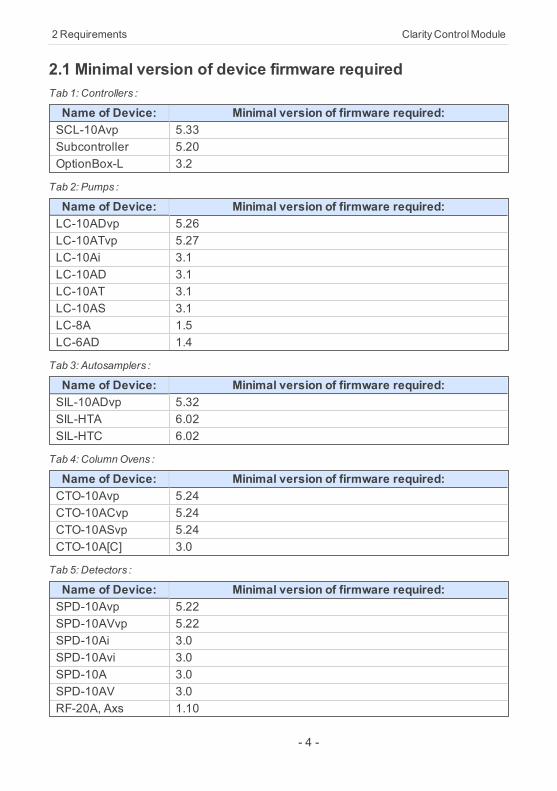
2.1 Minimal version of device firmware requiredTab 1: Controllers :
Name of Device: Minimal version of firmware required:SCL-10Avp 5.33Subcontroller 5.20OptionBox-L 3.2
Tab 2: Pumps :
Name of Device: Minimal version of firmware required:LC-10ADvp 5.26LC-10ATvp 5.27LC-10Ai 3.1LC-10AD 3.1LC-10AT 3.1LC-10AS 3.1LC-8A 1.5LC-6AD 1.4
Tab 3: Autosamplers :
Name of Device: Minimal version of firmware required:SIL-10ADvp 5.32SIL-HTA 6.02SIL-HTC 6.02
Tab 4: ColumnOvens :
Name of Device: Minimal version of firmware required:CTO-10Avp 5.24CTO-10ACvp 5.24CTO-10ASvp 5.24CTO-10A[C] 3.0
Tab 5: Detectors :
Name of Device: Minimal version of firmware required:SPD-10Avp 5.22SPD-10AVvp 5.22SPD-10Ai 3.0SPD-10Avi 3.0SPD-10A 3.0SPD-10AV 3.0RF-20A, Axs 1.10
- 4 -
Shimadzu LC-10/20 System 3 Installation Procedure
3 Installation Procedure3.1 Shimadzu LC-10/20 System communication
Shimadzu LC-10/20 System may be controlled either via standard serialcross DB9F-DB9F cable or via cross LAN cable, depending on the type ofconnector present on the controller. LAN communication is only presenton LC-20 line controllers.
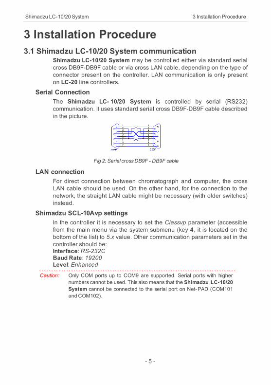
Serial ConnectionThe Shimadzu LC- 10/20 System is controlled by serial (RS232)communication. It uses standard serial cross DB9F-DB9F cable describedin the picture.
Fig 2: Serial crossDB9F - DB9F cable
LAN connection For direct connection between chromatograph and computer, the crossLAN cable should be used. On the other hand, for the connection to thenetwork, the straight LAN cable might be necessary (with older switches)instead.
Shimadzu SCL-10Avp settingsIn the controller it is necessary to set the Classvp parameter (accessiblefrom the main menu via the system submenu (key 4, it is located on thebottom of the list) to 5.x value. Other communication parameters set in thecontroller should be:Interface: RS-232CBaud Rate: 19200Level: Enhanced
Caution: Only COM ports up to COM9 are supported. Serial ports with highernumbers cannot be used. This also means that the Shimadzu LC-10/20System cannot be connected to the serial port on Net-PAD (COM101and COM102).
- 5 -
3 Installation Procedure ClarityControlModule
LC-20 components with SCL-10Avp controllerShimadzu LC-20 components have to be set to the LC-10 emulationmode when they should be working under the LC-10 controller. This isdone from the device's keyboard according to this procedure (procedurepresented on the LC-20 series pump, may differ slightly for other devices):
Press the VP button on the devices's front keyboard until theCALIBRATION inscription is shown on the display.Press the func button to enter the configuration. The password has to befilled in.
Note: The default password is00000.
Press the func button repeatedly until the OP MODE inscription is shownon the display.Enter the desired number (1 for the pump) to switch the device to the SCL-10Avp emulation mode and press the enter button.Switch the device off and on again. The new communication parametersshould be saved and used.
The procedure is in detail described in the LC-20 hardware manualprovided by the Shimadzu company.
CBM-20A(Lite) settingsIt is necessary to set the communication parameters in the controller. FromClarity version 2.6.5, the parameters are:Communication Mode: ClassVPInterface: RS232/Ethernet (depending on the desired connection type)The exact procedure is described in the controllers hardware manual.
- 6 -
Shimadzu LC-10/20 System 3 Installation Procedure
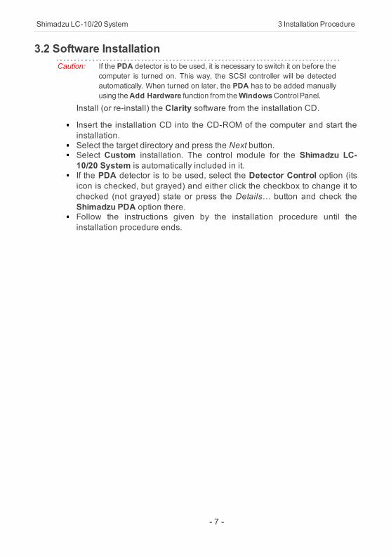
3.2 Software InstallationCaution: If the PDA detector is to be used, it is necessary to switch it on before the
computer is turned on. This way, the SCSI controller will be detectedautomatically. When turned on later, the PDA has to be added manuallyusing theAdd Hardware function from theWindowsControl Panel.
Install (or re-install) the Clarity software from the installation CD.
Insert the installation CD into the CD-ROM of the computer and start theinstallation.Select the target directory and press the Next button.Select Custom installation. The control module for the Shimadzu LC-10/20 System is automatically included in it.If the PDA detector is to be used, select the Detector Control option (itsicon is checked, but grayed) and either click the checkbox to change it tochecked (not grayed) state or press the Details… button and check theShimadzu PDA option there.Follow the instructions given by the installation procedure until theinstallation procedure ends.
- 7 -
3 Installation Procedure ClarityControlModule
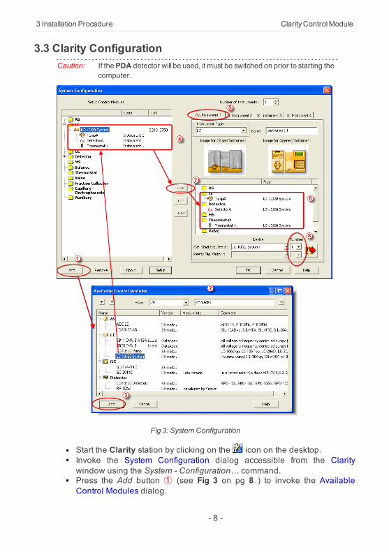
3.3 Clarity ConfigurationCaution: If thePDA detector will be used, it must be switched on prior to starting the
computer.
Fig 3: SystemConfiguration
Start the Clarity station by clicking on the icon on the desktop.Invoke the System Configuration dialog accessible from the Claritywindow using the System - Configuration… command.Press the Add button ① (see Fig 3 on pg 8 .) to invoke the AvailableControl Modules dialog.
- 8 -
Shimadzu LC-10/20 System 3 Installation Procedure
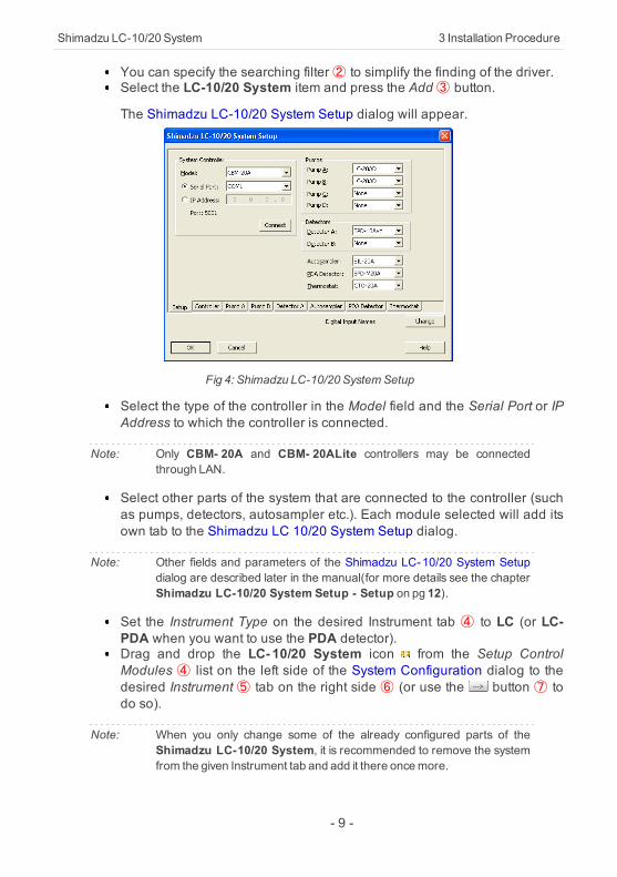
You can specify the searching filter② to simplify the finding of the driver.Select the LC-10/20 System item and press the Add ③ button.
The Shimadzu LC-10/20 System Setup dialog will appear.
Fig 4: Shimadzu LC-10/20 SystemSetup
Select the type of the controller in the Model field and the Serial Port or IPAddress to which the controller is connected.
Note: Only CBM- 20A and CBM- 20ALite controllers may be connectedthrough LAN.
Select other parts of the system that are connected to the controller (suchas pumps, detectors, autosampler etc.). Each module selected will add itsown tab to the Shimadzu LC 10/20 System Setup dialog.
Note: Other fields and parameters of the Shimadzu LC-10/20 System Setupdialog are described later in the manual(for more details see the chapterShimadzu LC-10/20 System Setup - Setup on pg 12).
Set the Instrument Type on the desired Instrument tab ④ to LC (or LC-PDA when you want to use the PDA detector).Drag and drop the LC-10/20 System icon from the Setup ControlModules ④ list on the left side of the System Configuration dialog to thedesired Instrument ⑤ tab on the right side ⑥ (or use the button ⑦ todo so).
Note: When you only change some of the already configured parts of theShimadzu LC-10/20 System, it is recommended to remove the systemfrom the given Instrument tab and add it there oncemore.
- 9 -

3 Installation Procedure ClarityControlModule
Set the Ext. Start Dig. Input and Ready Dig. Output numbers ⑧ for youracquisition card according to the wires being used for synchronization.
Caution: The Shimadzu LC-10/20 Systemmust have all subdevices configuredon the same Instrument (cannot have parts of it on different Instruments)and no sub- device may be left unconfigured (if any subdevice isconfigured on the Instrument, all subdevicesmust be).
- 10 -
Shimadzu LC-10/20 System 3 Installation Procedure
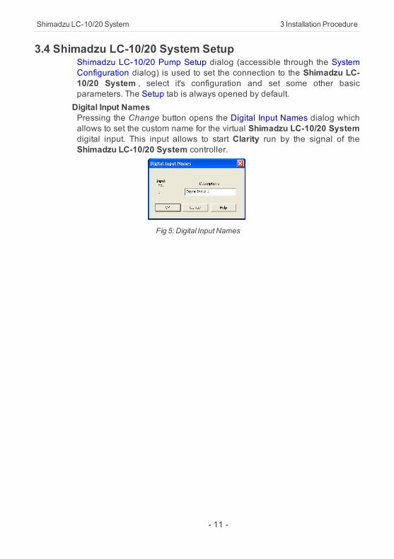
3.4 Shimadzu LC-10/20 System SetupShimadzu LC-10/20 Pump Setup dialog (accessible through the SystemConfiguration dialog) is used to set the connection to the Shimadzu LC-10/20 System , select it's configuration and set some other basicparameters. The Setup tab is always opened by default.Digital Input NamesPressing the Change button opens the Digital Input Names dialog whichallows to set the custom name for the virtual Shimadzu LC-10/20 Systemdigital input. This input allows to start Clarity run by the signal of theShimadzu LC-10/20 System controller.
Fig 5: Digital Input Names
- 11 -
3 Installation Procedure ClarityControlModule
3.4.1 Shimadzu LC-10/20 System Setup - Setup
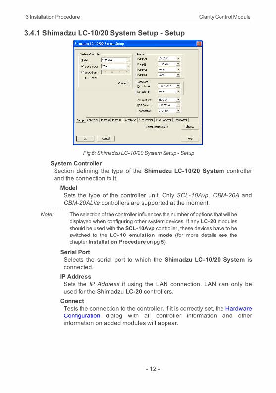
Fig 6: Shimadzu LC-10/20 SystemSetup - Setup
System ControllerSection defining the type of the Shimadzu LC-10/20 System controllerand the connection to it.ModelSets the type of the controller unit. Only SCL-10Avp , CBM-20A andCBM-20ALite controllers are supported at the moment.
Note: The selection of the controller influences the number of options that will bedisplayed when configuring other system devices. If any LC-20 modulesshould be used with the SCL-10Avp controller, these devices have to beswitched to the LC- 10 emulation mode (for more details see thechapter Installation Procedure on pg 5).
Serial PortSelects the serial port to which the Shimadzu LC-10/20 System isconnected.IP AddressSets the IP Address if using the LAN connection. LAN can only beused for the Shimadzu LC-20 controllers.ConnectTests the connection to the controller. If it is correctly set, the HardwareConfiguration dialog with all controller information and otherinformation on added modules will appear.
- 12 -
Shimadzu LC-10/20 System 3 Installation Procedure
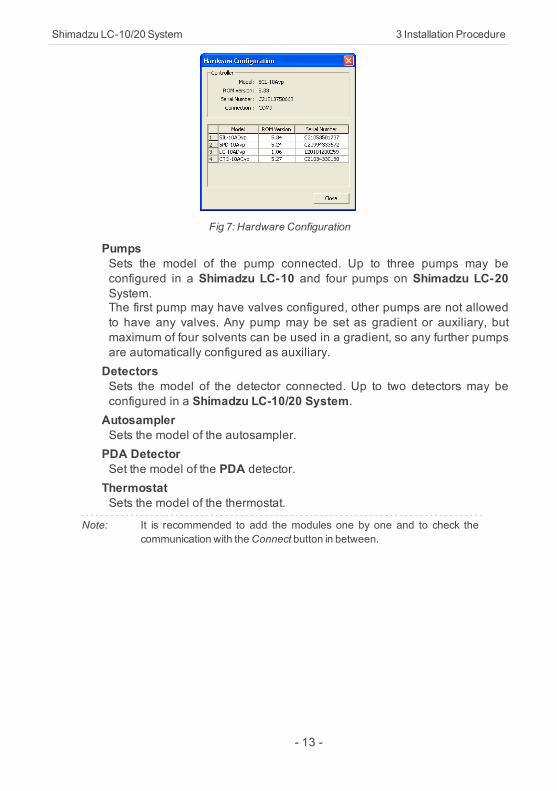
Fig 7: Hardware Configuration
PumpsSets the model of the pump connected. Up to three pumps may beconfigured in a Shimadzu LC-10 and four pumps on Shimadzu LC-20System.The first pump may have valves configured, other pumps are not allowedto have any valves. Any pump may be set as gradient or auxiliary, butmaximum of four solvents can be used in a gradient, so any further pumpsare automatically configured as auxiliary.DetectorsSets the model of the detector connected. Up to two detectors may beconfigured in a Shimadzu LC-10/20 System.AutosamplerSets the model of the autosampler.PDA DetectorSet the model of the PDA detector.ThermostatSets the model of the thermostat.
Note: It is recommended to add the modules one by one and to check thecommunication with theConnect button in between.
- 13 -
3 Installation Procedure ClarityControlModule
3.4.2 Shimadzu LC-10/20 System Setup - Controller
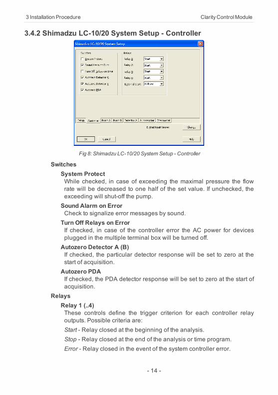
Fig 8: Shimadzu LC-10/20 SystemSetup - Controller
SwitchesSystem ProtectWhile checked, in case of exceeding the maximal pressure the flowrate will be decreased to one half of the set value. If unchecked, theexceeding will shut-off the pump.Sound Alarm on ErrorCheck to signalize error messages by sound.Turn Off Relays on ErrorIf checked, in case of the controller error the AC power for devicesplugged in the multiple terminal box will be turned off.Autozero Detector A (B)If checked, the particular detector response will be set to zero at thestart of acquisition.Autozero PDAIf checked, the PDA detector response will be set to zero at the start ofacquisition.
RelaysRelay 1 (..4)These controls define the trigger criterion for each controller relayoutputs. Possible criteria are:Start - Relay closed at the beginning of the analysis.Stop - Relay closed at the end of the analysis or time program.Error - Relay closed in the event of the system controller error.
- 14 -

Shimadzu LC-10/20 System 3 Installation Procedure
Event - Relay closed on the time basis as the event of the HPLC timeprogram.External StartThis control sets the conditions for closing the controllers start relays atthe beginning of the analysis. Possible options are:Disable - External start is disabled.All Runs - Closes start relays at each analysis start including startswith no injection.Inject Only - Closes start relays only after starting the analysis with theinjection performed.
- 15 -

Shimadzu LC-10/20 System 4Using the controlmodule
4 Using the control moduleSeveral new tabs appear in the Method Setup dialog, based on thesettings performed in the Shimadzu LC-10/20 System Setup dialog. Thesenew tabs enable the setting of the Shimadzu system operation program.
Note: The instrument method is always sent to the Shimadzu LC- 10/20Systemasa whole.
- 16 -
4 Using the controlmodule ClarityControlModule
4.1 Pump4.1.1 Shimadzu LC-10/20 System Setup - Pump
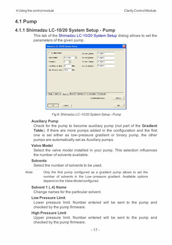
This tab of the Shimadzu LC-10/20 System Setup dialog allows to set theparameters of the given pump.
Fig 9: Shimadzu LC-10/20 SystemSetup - Pump
Auxiliary PumpCheck for the pump to become auxiliary pump (not part of the GradientTable). If there are more pumps added in the configuration and the firstone is set either as low-pressure gradient or binary pump, the otherpumps are automatically set as Auxiliary pumps.Valve ModelSelect the valve model installed in your pump. This selection influencesthe number of solvents available.SolventsSelect the number of solvents to be used.
Note: Only the first pump configured as a gradient pump allows to set thenumber of solvents in the Low- pressure gradient. Available optionsdepend on theValveModel configured.
Solvent 1 (..4) NameChange names for the particular solvent.Low Pressure LimitLower pressure limit. Number entered will be sent to the pump andchecked by the pump firmware.High Pressure LimitUpper pressure limit. Number entered will be sent to the pump andchecked by the pump firmware.
- 17 -

Shimadzu LC-10/20 System 4Using the controlmodule
Note: Exceeding of High Pressure Limit or Low Pressure Limit defined here willcause a system error, requiring the closure and reopening of the givenInstrument.
- 18 -
4 Using the controlmodule ClarityControlModule
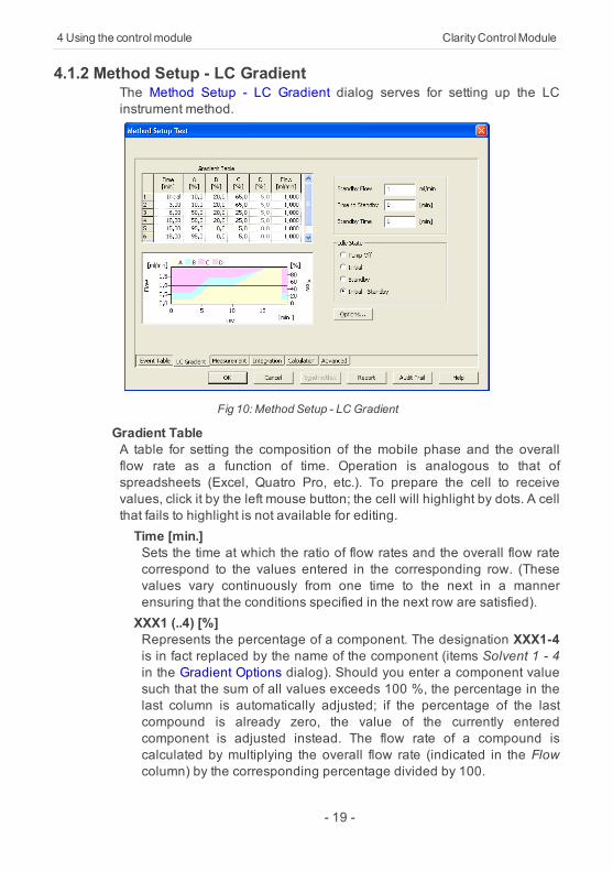
4.1.2 Method Setup - LC GradientThe Method Setup - LC Gradient dialog serves for setting up the LCinstrument method.
Fig 10: Method Setup - LC Gradient
Gradient TableA table for setting the composition of the mobile phase and the overallflow rate as a function of time. Operation is analogous to that ofspreadsheets (Excel, Quatro Pro, etc.). To prepare the cell to receivevalues, click it by the left mouse button; the cell will highlight by dots. A cellthat fails to highlight is not available for editing.Time [min.]Sets the time at which the ratio of flow rates and the overall flow ratecorrespond to the values entered in the corresponding row. (Thesevalues vary continuously from one time to the next in a mannerensuring that the conditions specified in the next row are satisfied).XXX1 (..4) [%]Represents the percentage of a component. The designation XXX1-4is in fact replaced by the name of the component (items Solvent 1 - 4in the Gradient Options dialog). Should you enter a component valuesuch that the sum of all values exceeds 100 %, the percentage in thelast column is automatically adjusted; if the percentage of the lastcompound is already zero, the value of the currently enteredcomponent is adjusted instead. The flow rate of a compound iscalculated by multiplying the overall flow rate (indicated in the Flowcolumn) by the corresponding percentage divided by 100.
- 19 -
Shimadzu LC-10/20 System 4Using the controlmodule
Flow [ml/min]Indicates the overall flow rate through the column. The entered valueapplies to the time specified in the corresponding row.
Note: The values of the Flow for the Shimadzu LC-10/20 pumps vary in certainrange according to the type of the pump. Check the device manual forvalid Flow ranges for your pump.
GraphThe graph depicts the percentage of components as a function of timetogether with the overall flow rate. Data are taken over from the GradientTable . Changes effected in this table are immediately reflected in thegraph. Legend in the header of the graph indicates the assignment ofcolors to individual components. The assignment is fixed and individualcomponents are displayed in the graph from bottom to top. The flow rate isdisplayed as a black line.The graph has two vertical axes: the axis on the left refers to the mixingratio, the one on the right to the overall flow rate.Parameters
Standby FlowSets the overall flow rate through the column in the STANDBY statereached after the last row of the table has been performed and thetime period defined in the Time to Standby field has passed. Theduration of this state is defined by the Standby Time item. The ratio ofindividual components in the respective STANDBY and IDLE states isgiven by the first row of the Gradient Table (the Initial row).Time to Standby [min]Indicates the time during which the flow rate and mobile phasecomposition changes continuously between the last values entered inthe table and the values defined by Standby Flow field and the Initialrow mobile phase composition.This time is included in the analysis time (the Instrument is in theCONTROL state). In case when the Time to Standby is zero, there isstep change from flow and components percentage specified on thelast row of gradient table to that specified for STANDBY state.Standby Time [min]The time during which the flow rate is maintained at Standby Flow .This time is included in the analysis time (the Instrument is in theCONTROL state).
Idle StateAn item specifying the overall flow rate through the column outside theinstrument method. The following options are possible:Pump OffThe flow rates of all components are zero.
- 20 -
4 Using the controlmodule ClarityControlModule
Caution: Be careful as this settingmaydamage the column in some cases.
InitialThe flow rate is defined by the first row of the Gradient Table (theInitial row).StandbyThe flow rate is the same as in the STANDBY mode and, accordingly,corresponds to the value entered in Standby Flow field.Initial - StandbyThe flow is defined by the first row of the gradient table (the Initial row)after the method is sent, or by the value entered in the Standby Flowfield after the method finishes.
The IDLE state comes into effect each time an Instrument is opened, at theend or after abortion of an analysis by the Abort command, and is alsomaintained after the Clarity program is shut down.The mixing ratio of individual components in both the IDLE and STANDBYstates is given by the first row of the Gradient Table (the Initial row).
Note: There is a step change in the flow and components percentage from thevalues specified for the STANDBY state to those specified for the IDLEstate if the Idle State field is not set toStandby.
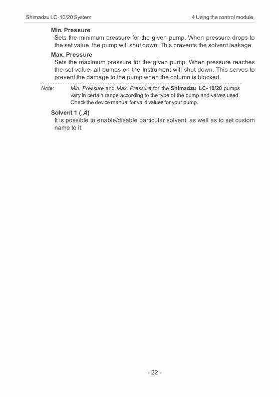
4.1.2.1 Gradient OptionsInvoke the Options… button in the Method Setup - LC Gradient dialog toopen the Gradient Options dialog. This dialog allows to set the customname for particular solvents, to switch whether they are used or not in thegradient and to set the warning levels for pressure to prevent the damageto hardware.The abovementioned pressure limits are checked in the software.Pressure check for low pressure limit doesn’t start immediately after pumpis started, but with few minutes delay. During this delay the pressure inchromatographic system can stabilize.In addition to those limits, a pressure limits are set in the Shimadzu LC-10/20 System Setup - Pump dialog. Those limits are checked in the pumpfirmware. As they will cause a system error, they should be set outside thelimits defined here in the Gradient Options dialog.
Fig 11: Gradient Options
- 21 -
Shimadzu LC-10/20 System 4Using the controlmodule
Min. PressureSets the minimum pressure for the given pump. When pressure drops tothe set value, the pump will shut down. This prevents the solvent leakage.Max. PressureSets the maximum pressure for the given pump. When pressure reachesthe set value, all pumps on the Instrument will shut down. This serves toprevent the damage to the pump when the column is blocked.
Note: Min. Pressure and Max. Pressure for the Shimadzu LC-10/20 pumpsvary in certain range according to the type of the pump and valves used.Check the devicemanual for valid values for your pump.
Solvent 1 (..4)It is possible to enable/disable particular solvent, as well as to set customname to it.
- 22 -
4 Using the controlmodule ClarityControlModule
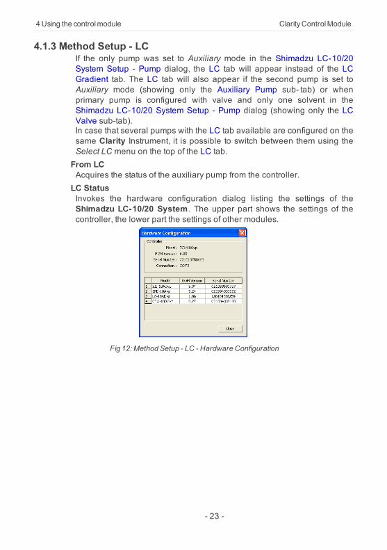
4.1.3 Method Setup - LCIf the only pump was set to Auxiliary mode in the Shimadzu LC-10/20System Setup - Pump dialog, the LC tab will appear instead of the LCGradient tab. The LC tab will also appear if the second pump is set toAuxiliary mode (showing only the Auxiliary Pump sub- tab) or whenprimary pump is configured with valve and only one solvent in theShimadzu LC-10/20 System Setup - Pump dialog (showing only the LCValve sub-tab).In case that several pumps with the LC tab available are configured on thesame Clarity Instrument, it is possible to switch between them using theSelect LC menu on the top of the LC tab.From LCAcquires the status of the auxiliary pump from the controller.LC StatusInvokes the hardware configuration dialog listing the settings of theShimadzu LC-10/20 System . The upper part shows the settings of thecontroller, the lower part the settings of other modules.
Fig 12: Method Setup - LC - Hardware Configuration
- 23 -
Shimadzu LC-10/20 System 4Using the controlmodule
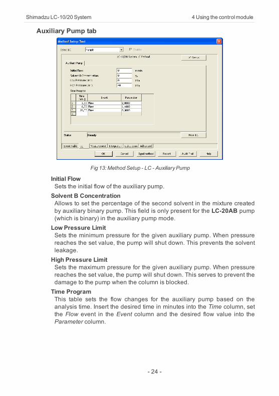
Auxiliary Pump tab
Fig 13: Method Setup - LC - AuxiliaryPump
Initial FlowSets the initial flow of the auxiliary pump.Solvent B ConcentrationAllows to set the percentage of the second solvent in the mixture createdby auxiliary binary pump. This field is only present for the LC-20AB pump(which is binary) in the auxiliary pump mode.Low Pressure LimitSets the minimum pressure for the given auxiliary pump. When pressurereaches the set value, the pump will shut down. This prevents the solventleakage.High Pressure LimitSets the maximum pressure for the given auxiliary pump. When pressurereaches the set value, the pump will shut down. This serves to prevent thedamage to the pump when the column is blocked.Time ProgramThis table sets the flow changes for the auxiliary pump based on theanalysis time. Insert the desired time in minutes into the Time column, setthe Flow event in the Event column and the desired flow value into theParameter column.
- 24 -
4 Using the controlmodule ClarityControlModule
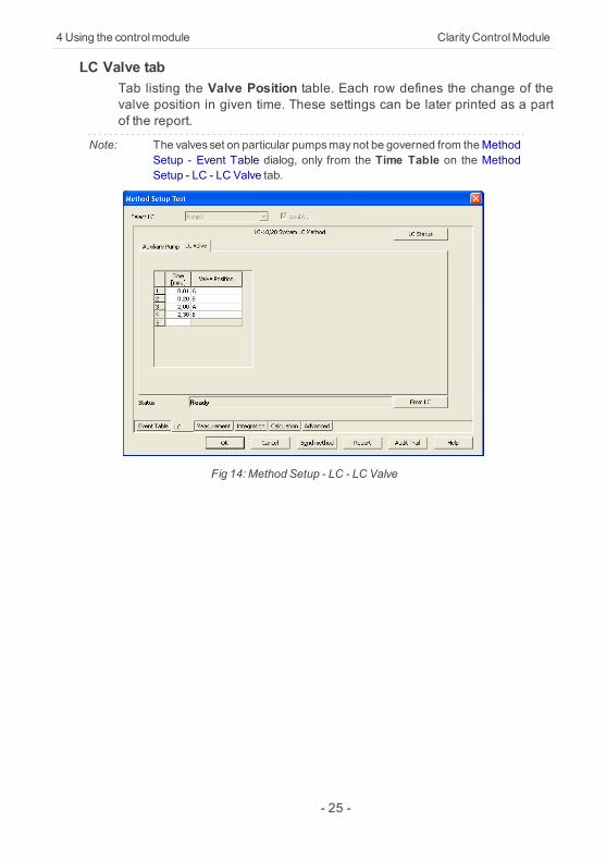
LC Valve tabTab listing the Valve Position table. Each row defines the change of thevalve position in given time. These settings can be later printed as a partof the report.
Note: The valves set on particular pumpsmaynot be governed from theMethodSetup - Event Table dialog, only from the Time Table on the MethodSetup - LC - LC Valve tab.
Fig 14: Method Setup - LC - LC Valve
- 25 -
Shimadzu LC-10/20 System 4Using the controlmodule
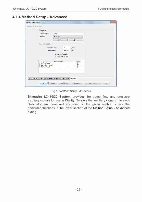
4.1.4 Method Setup - Advanced
Fig 15: Method Setup - Advanced
Shimadzu LC- 10/20 System provides the pump flow and pressureauxiliary signals for use in Clarity. To save the auxiliary signals into eachchromatogram measured according to the given method, check theparticular checkbox in the lower section of the Method Setup - Advanceddialog.
- 26 -
4 Using the controlmodule ClarityControlModule
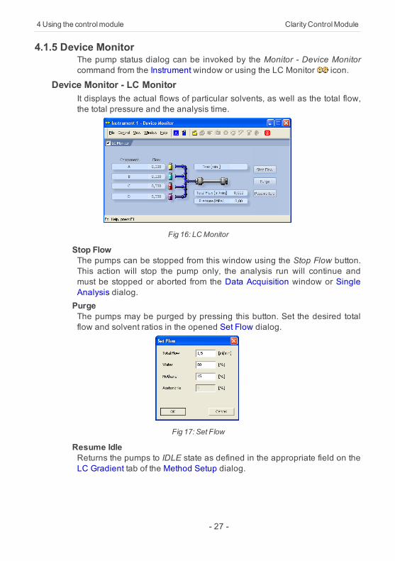
4.1.5 Device MonitorThe pump status dialog can be invoked by the Monitor - Device Monitorcommand from the Instrument window or using the LC Monitor icon.
Device Monitor - LC MonitorIt displays the actual flows of particular solvents, as well as the total flow,the total pressure and the analysis time.
Fig 16: LCMonitor
Stop FlowThe pumps can be stopped from this window using the Stop Flow button.This action will stop the pump only, the analysis run will continue andmust be stopped or aborted from the Data Acquisition window or SingleAnalysis dialog.PurgeThe pumps may be purged by pressing this button. Set the desired totalflow and solvent ratios in the opened Set Flow dialog.
Fig 17: Set Flow
Resume IdleReturns the pumps to IDLE state as defined in the appropriate field on theLC Gradient tab of the Method Setup dialog.
- 27 -
Shimadzu LC-10/20 System 4Using the controlmodule
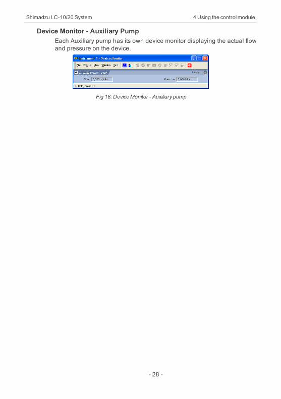
Device Monitor - Auxiliary PumpEach Auxiliary pump has its own device monitor displaying the actual flowand pressure on the device.
Fig 18: DeviceMonitor - Auxiliary pump
- 28 -
4 Using the controlmodule ClarityControlModule
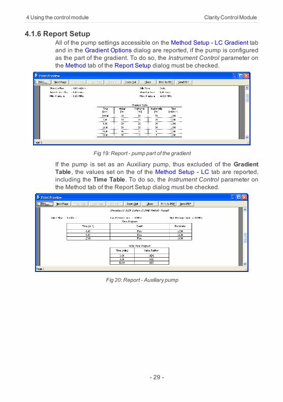
4.1.6 Report SetupAll of the pump settings accessible on the Method Setup - LC Gradient taband in the Gradient Options dialog are reported, if the pump is configuredas the part of the gradient. To do so, the Instrument Control parameter onthe Method tab of the Report Setup dialog must be checked.
Fig 19: Report - pump part of the gradient
If the pump is set as an Auxiliary pump, thus excluded of the GradientTable , the values set on the of the Method Setup - LC tab are reported,including the Time Table. To do so, the Instrument Control parameter onthe Method tab of the Report Setup dialog must be checked.
Fig 20: Report - Auxiliary pump
- 29 -
Shimadzu LC-10/20 System 4Using the controlmodule
4.2 Detector4.2.1 Shimadzu LC-10/20 System Setup - Detector
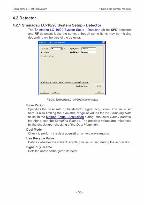
The Shimadzu LC-10/20 System Setup - Detector tab for SPD detectorsand RF detectors looks the same, although some items may be missingdepending on the type of the detector.
Fig 21: Shimadzu LC-10/20 Detector setup
Base PeriodSpecifies the base rate of the detector signal acquisition. The value sethere is also limiting the available range of values for the Sampling Rateas set in the Method Setup - Acquisition dialog - the lower Base Period is,the higher can the Sampling Rate be. The possible values are influencedby the checking/unchecking of the Dual Mode item.Dual ModeCheck to perform the data acquisition on two wavelengths.Use Recycle ValveDefines whether the solvent recycling valve is used during the acquisition.Signal 1 (2) NameSets the name of the given detector.
- 30 -
4 Using the controlmodule ClarityControlModule
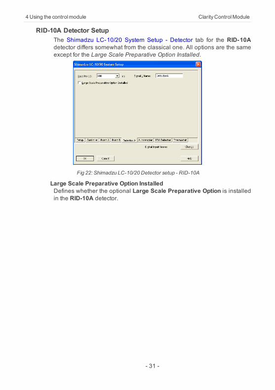
RID-10A Detector SetupThe Shimadzu LC-10/20 System Setup - Detector tab for the RID-10Adetector differs somewhat from the classical one. All options are the sameexcept for the Large Scale Preparative Option Installed.
Fig 22: Shimadzu LC-10/20 Detector setup - RID-10A
Large Scale Preparative Option InstalledDefines whether the optional Large Scale Preparative Option is installedin the RID-10A detector.
- 31 -
Shimadzu LC-10/20 System 4Using the controlmodule
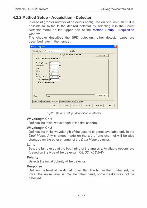
4.2.2 Method Setup - Acquisition - DetectorIn case of greater number of detectors configured on one Instrument, it ispossible to switch to the desired detector by selecting it in the SelectDetector menu on the upper part of the Method Setup - Acquisitionwindow.The chapter describes the SPD detectors, other detector types aredescribed later in the manual.
Fig 23: Method Setup - Acquisition - Detector
Wavelength Ch.1Defines the initial wavelength of the first channel.Wavelength Ch.2Defines the initial wavelength of the second channel, available only in theDual Mode . Any changes made on the tab of one channel will be alsochanged on the other channel of the Dual Mode detector.LampSets the lamp used at the beginning of the analysis. Available options are(based on the type of the detector):Off, D2,W, D2+WPolaritySelects the initial polarity of the detector.ResponseDefines the level of the digital noise filter. The higher the number set, thelower the noise level is. On the other hand, some peaks may not bedetected.
- 32 -
4 Using the controlmodule ClarityControlModule
Sampling RateSets the sampling rate of the detector. The available detector sample ratesare dependent on the Base Period settings on the Shimadzu LC-10/20System Setup - Detector tab - by using the shortest Base Period of 20 ms,the Sampling Rate can be set up to 50 Hz. Please note that in dual modethe Base Period is limited to 100 ms and maximum Sampling Rate to 10Hz.Cell TemperatureSets the cell temperature of the given detector. The Value range isbetween 9 and 50 °C.Check Cell TemperatureIf checked, doesn't allow the Instrument to become READY until thetemperature is not close to the temperature set in the CellTemperature field (with the tolerance of 1,5 °C).
- 33 -
Shimadzu LC-10/20 System 4Using the controlmodule
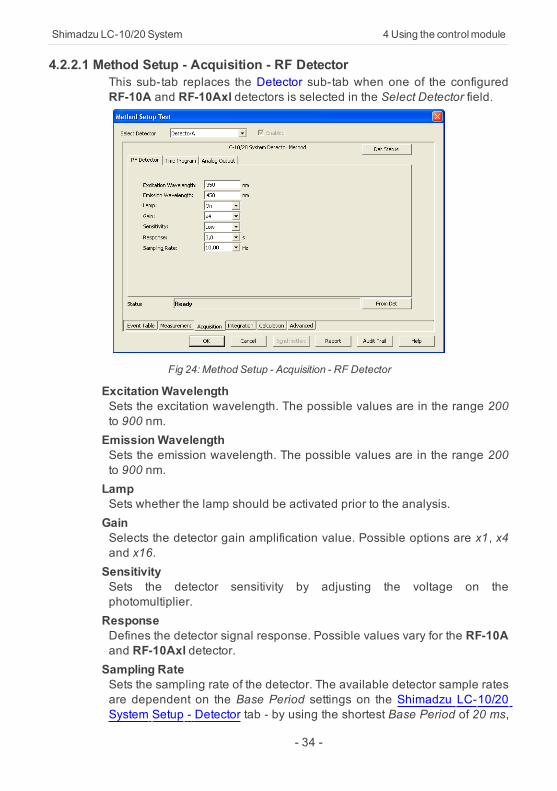
4.2.2.1 Method Setup - Acquisition - RF DetectorThis sub-tab replaces the Detector sub-tab when one of the configuredRF-10A and RF-10Axl detectors is selected in the Select Detector field.
Fig 24: Method Setup - Acquisition - RF Detector
Excitation WavelengthSets the excitation wavelength. The possible values are in the range 200to 900 nm.EmissionWavelengthSets the emission wavelength. The possible values are in the range 200to 900 nm.LampSets whether the lamp should be activated prior to the analysis.GainSelects the detector gain amplification value. Possible options are x1, x4and x16.SensitivitySets the detector sensitivity by adjusting the voltage on thephotomultiplier.ResponseDefines the detector signal response. Possible values vary for the RF-10Aand RF-10Axl detector.Sampling RateSets the sampling rate of the detector. The available detector sample ratesare dependent on the Base Period settings on the Shimadzu LC-10/20System Setup - Detector tab - by using the shortest Base Period of 20 ms,
- 34 -

4 Using the controlmodule ClarityControlModule
the Sampling Rate can be set up to 50 Hz. Please note that in dual modethe Base Period is limited to 100 ms and maximum Sampling Rate to 10Hz.
- 35 -
Shimadzu LC-10/20 System 4Using the controlmodule
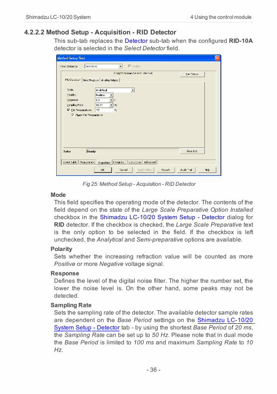
4.2.2.2 Method Setup - Acquisition - RID DetectorThis sub-tab replaces the Detector sub-tab when the configured RID-10Adetector is selected in the Select Detector field.
Fig 25: Method Setup - Acquisition - RID Detector
ModeThis field specifies the operating mode of the detector. The contents of thefield depend on the state of the Large Scale Preparative Option Installedcheckbox in the Shimadzu LC-10/20 System Setup - Detector dialog forRID detector. If the checkbox is checked, the Large Scale Preparative textis the only option to be selected in the field. If the checkbox is leftunchecked, the Analytical and Semi-preparative options are available.PolaritySets whether the increasing refraction value will be counted as morePositive or more Negative voltage signal.ResponseDefines the level of the digital noise filter. The higher the number set, thelower the noise level is. On the other hand, some peaks may not bedetected.Sampling RateSets the sampling rate of the detector. The available detector sample ratesare dependent on the Base Period settings on the Shimadzu LC-10/20System Setup - Detector tab - by using the shortest Base Period of 20 ms,the Sampling Rate can be set up to 50 Hz. Please note that in dual modethe Base Period is limited to 100 ms and maximum Sampling Rate to 10Hz.
- 36 -

4 Using the controlmodule ClarityControlModule
Cell TemperatureSets the temperature of the detector cell.Check Cell TemperatureWhen checked, the Instrument will not be ready until the actualtemperature will reach the set value (with the 1.5 °C tolerance). Whilethe checkbox is unchecked, no temperature verification will beperformed.
- 37 -
Shimadzu LC-10/20 System 4Using the controlmodule
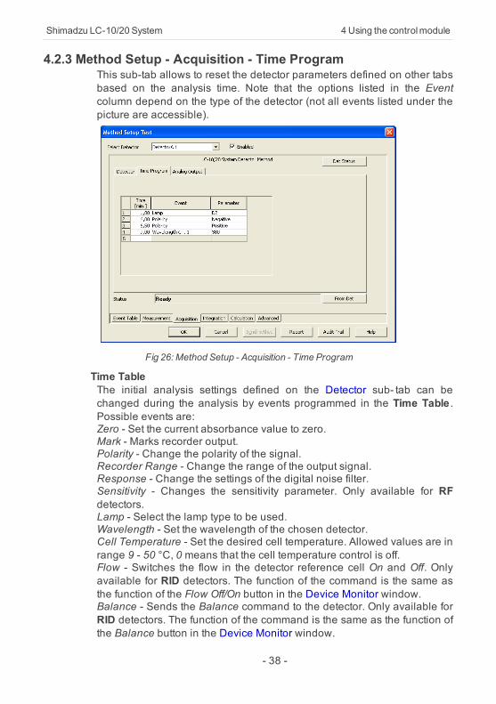
4.2.3 Method Setup - Acquisition - Time ProgramThis sub-tab allows to reset the detector parameters defined on other tabsbased on the analysis time. Note that the options listed in the Eventcolumn depend on the type of the detector (not all events listed under thepicture are accessible).
Fig 26: Method Setup - Acquisition - Time Program
Time TableThe initial analysis settings defined on the Detector sub- tab can bechanged during the analysis by events programmed in the Time Table .Possible events are:Zero - Set the current absorbance value to zero.Mark - Marks recorder output.Polarity - Change the polarity of the signal.Recorder Range - Change the range of the output signal.Response - Change the settings of the digital noise filter.Sensitivity - Changes the sensitivity parameter. Only available for RFdetectors.Lamp - Select the lamp type to be used.Wavelength - Set the wavelength of the chosen detector.Cell Temperature - Set the desired cell temperature. Allowed values are inrange 9 - 50 °C, 0 means that the cell temperature control is off.Flow - Switches the flow in the detector reference cell On and Off. Onlyavailable for RID detectors. The function of the command is the same asthe function of the Flow Off/On button in the Device Monitor window.Balance - Sends the Balance command to the detector. Only available forRID detectors. The function of the command is the same as the function ofthe Balance button in the Device Monitor window.
- 38 -

4 Using the controlmodule ClarityControlModule
Gain - Change the current Gain parameter. Only available for RFdetectors.Excitation Wavelength - Change the current Excitation Wavelengthparameter. Only available for RF detectors.Emission Wavelength - Change the current Emission Wavelengthparameter. Only available for RF detectors.
- 39 -
Shimadzu LC-10/20 System 4Using the controlmodule
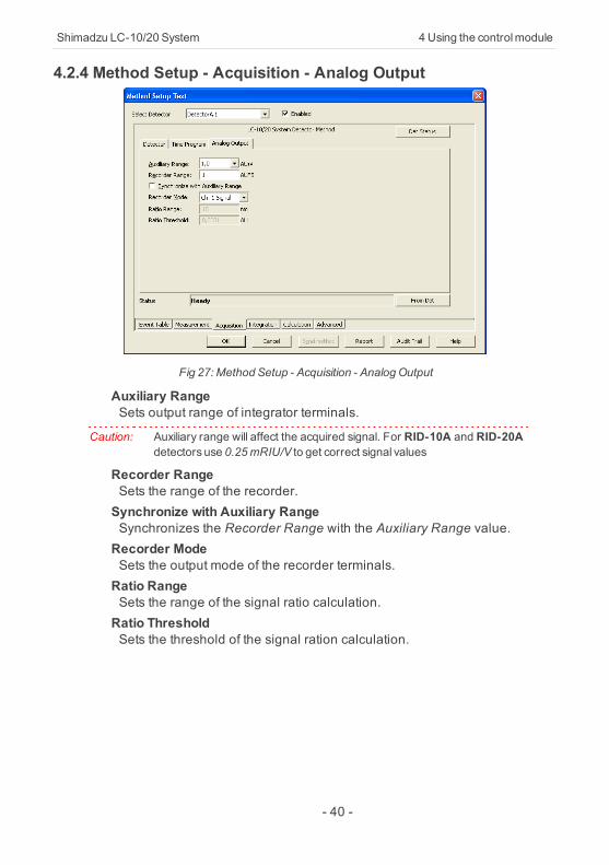
4.2.4 Method Setup - Acquisition - Analog Output
Fig 27: Method Setup - Acquisition - AnalogOutput
Auxiliary RangeSets output range of integrator terminals.
Caution: Auxiliary range will affect the acquired signal. For RID-10A and RID-20Adetectors use 0.25mRIU/V to get correct signal values
Recorder RangeSets the range of the recorder.Synchronize with Auxiliary RangeSynchronizes the Recorder Range with the Auxiliary Range value.Recorder ModeSets the output mode of the recorder terminals.Ratio RangeSets the range of the signal ratio calculation.Ratio ThresholdSets the threshold of the signal ration calculation.
- 40 -
4 Using the controlmodule ClarityControlModule
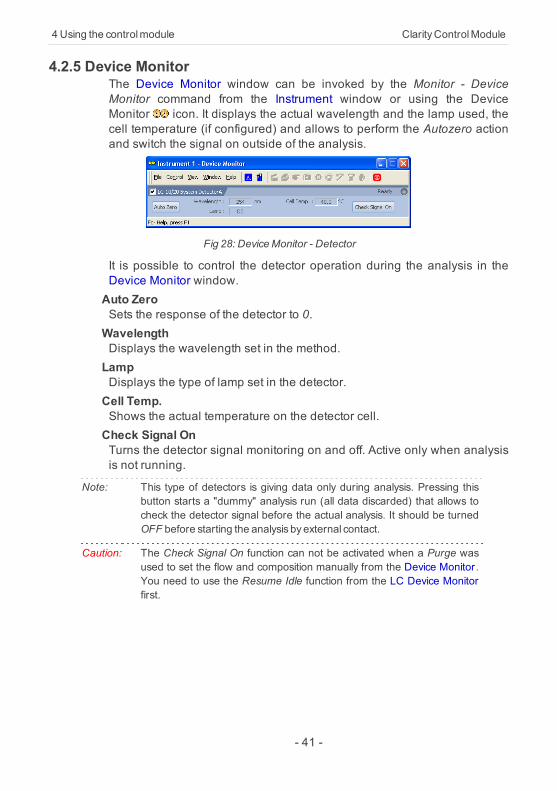
4.2.5 Device MonitorThe Device Monitor window can be invoked by the Monitor - DeviceMonitor command from the Instrument window or using the DeviceMonitor icon. It displays the actual wavelength and the lamp used, thecell temperature (if configured) and allows to perform the Autozero actionand switch the signal on outside of the analysis.
Fig 28: DeviceMonitor - Detector
It is possible to control the detector operation during the analysis in theDevice Monitor window.Auto ZeroSets the response of the detector to 0.WavelengthDisplays the wavelength set in the method.LampDisplays the type of lamp set in the detector.Cell Temp.Shows the actual temperature on the detector cell.Check Signal OnTurns the detector signal monitoring on and off. Active only when analysisis not running.
Note: This type of detectors is giving data only during analysis. Pressing thisbutton starts a "dummy" analysis run (all data discarded) that allows tocheck the detector signal before the actual analysis. It should be turnedOFF before starting the analysis byexternal contact.
Caution: The Check Signal On function can not be activated when a Purge wasused to set the flow and composition manually from the Device Monitor.You need to use the Resume Idle function from the LC Device Monitorfirst.
- 41 -
Shimadzu LC-10/20 System 4Using the controlmodule
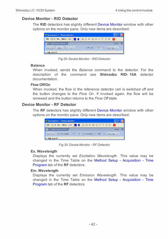
Device Monitor - RID DetectorThe RID detectors has slightly different Device Monitor window with otheroptions on the monitor pane. Only new items are described:
Fig 29: DeviceMonitor - RID Detector
BalanceWhen invoked, sends the Balance command to the detector. For thedescription of the command see Shimadzu RID- 10A detectordocumentation.Flow Off/OnWhen invoked, the flow in the reference detector cell is switched off andthe button changes to the Flow On . If invoked again, the flow will berenewed and the button returns to the Flow Off state.
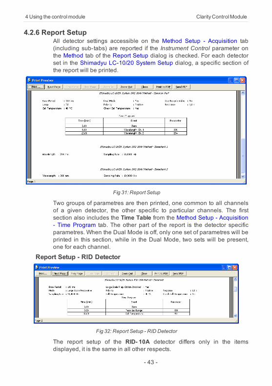
Device Monitor - RF DetectorThe RF detectors has slightly different Device Monitor window with otheroptions on the monitor pane. Only new items are described:
Fig 30: DeviceMonitor - RF Detector
Ex. WavelengthDisplays the currently set Excitation Wavelength . This value may bechanged in the Time Table on the Method Setup - Acquisition - TimeProgram tab of the RF detectors.Em. WavelengthDisplays the currently set Emission Wavelength . This value may bechanged in the Time Table on the Method Setup - Acquisition - TimeProgram tab of the RF detectors.
- 42 -
4 Using the controlmodule ClarityControlModule
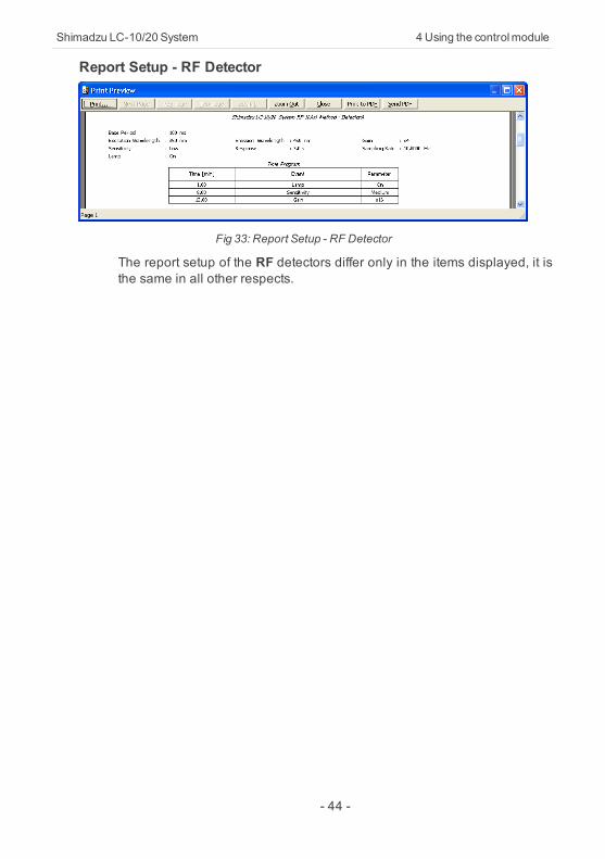
4.2.6 Report SetupAll detector settings accessible on the Method Setup - Acquisition tab(including sub-tabs) are reported if the Instrument Control parameter onthe Method tab of the Report Setup dialog is checked. For each detectorset in the Shimadyu LC-10/20 System Setup dialog, a specific section ofthe report will be printed.
Fig 31: Report Setup
Two groups of parametres are then printed, one common to all channelsof a given detector, the other specific to particular channels. The firstsection also includes the Time Table from the Method Setup - Acquisition- Time Program tab. The other part of the report is the detector specificparametres. When the Dual Mode is off, only one set of parametres will beprinted in this section, while in the Dual Mode, two sets will be present,one for each channel.
Report Setup - RID Detector
Fig 32: Report Setup - RID Detector
The report setup of the RID- 10A detector differs only in the itemsdisplayed, it is the same in all other respects.
- 43 -
Shimadzu LC-10/20 System 4Using the controlmodule
Report Setup - RF Detector
Fig 33: Report Setup - RF Detector
The report setup of the RF detectors differ only in the items displayed, it isthe same in all other respects.
- 44 -
4 Using the controlmodule ClarityControlModule
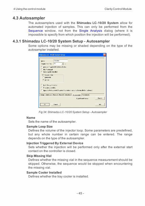
4.3 AutosamplerThe autosamplers used with the Shimadzu LC-10/20 System allow forautomated injection of samples. This can only be performed from theSequence window, not from the Single Analysis dialog (where it isimpossible to specify from which position the injection will be performed).
4.3.1 Shimadzu LC-10/20 System Setup - AutosamplerSome options may be missing or shaded depending on the type of theautosampler installed.
Fig 34: Shimadzu LC-10/20 SystemSetup - Autosampler
NameSets the name of the autosampler.Sample Loop SizeDefines the volume of the injector loop. Some parameters are predefined,but any whole number in certain range can be entered. The rangedepends on the type of the autosampler.Injection Triggered By External DeviceSets whether the injection will be performed only after the external startcontact on the controller is closed.Skip Missing VialDefines whether the missing vial in the sequence measurement should beskipped. Otherwise, the sequence would be stopped when encounteringthe missing vial.Sample Cooler InstalledDefines whether the tray cooler is installed.
- 45 -

Shimadzu LC-10/20 System 4Using the controlmodule
MTP Sample OrderDefines the numbering of wells in the plate when the MTP Tray is used. Ifother trays are used, this option is ignored. Possible parameters areHorizontal or Vertical.Rack Changer InstalledEnables the rack changer control in case a rack changer is installed.Rinse Pump InstalledEnables the control of the rinse pump (if it is installed).Supports PretreatmentEnables the display of the Pretreatment sub-tab of the Method Setup - ASdialog. For this option to function, it is necessary to have the Pretreatmentoption installed in the hardware.
- 46 -
4 Using the controlmodule ClarityControlModule
4.3.2 Method Setup - AS - Sampler
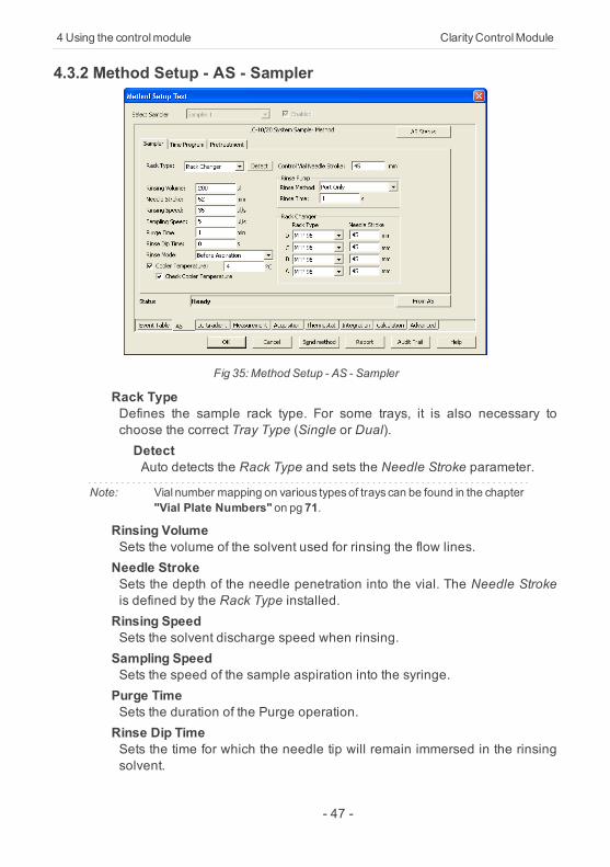
Fig 35: Method Setup - AS - Sampler
Rack TypeDefines the sample rack type. For some trays, it is also necessary tochoose the correct Tray Type (Single or Dual).DetectAuto detects the Rack Type and sets the Needle Stroke parameter.
Note: Vial number mapping on various typesof trays can be found in the chapter"Vial Plate Numbers" on pg 71.
Rinsing VolumeSets the volume of the solvent used for rinsing the flow lines.Needle StrokeSets the depth of the needle penetration into the vial. The Needle Strokeis defined by the Rack Type installed.Rinsing SpeedSets the solvent discharge speed when rinsing.Sampling SpeedSets the speed of the sample aspiration into the syringe.Purge TimeSets the duration of the Purge operation.Rinse Dip TimeSets the time for which the needle tip will remain immersed in the rinsingsolvent.
- 47 -
Shimadzu LC-10/20 System 4Using the controlmodule
Rinse ModeSets the time when the rinsing will be performed. Available options are NoRinsing , Before Aspiration , After Aspiration and Before and AfterAspiration.Cooler TemperatureEnables the cooling of the autosampler. This option is available only afterthe Sample Cooler Installed option was checked in the Shimadzu LC-10/20 System Setup - Autosampler dialog. The field than allows to set thedesired temperature.Check Cooler TemperatureIf checked, doesn't allow the Instrument to become READY until thetemperature is not close to the temperature set in the CoolerTemperature field (with the tolerance of 1,5 °C).
Control Vial Needle StrokeSets the needle depth used when aspirating from the Control Rack (usedwith the SIL-20 samplers).Rinse PumpSection enabled by checking the Rinse Pump Installed option in theShimadzu LC-10/20 System Setup - Autosampler dialog.Rinse MethodSets the method for the Rinse Pump . Port Only , Pump Only , PumpThen Port, Port Then Pump , Pump And Port Between Analyses andAuxiliary 1 (2) methods are available.Rinse TimeSets the length of the rinse. Possible values are integers in the range1 - 9.
Rack ChangerSection enabled by checking the Rack Changer Installed option in theShimadzu LC-10/20 System Setup - Autosampler dialog.Rack Type D..ASets the type of the rack for each position in the rack changer.Needle Stroke D..ASets the needle stroke depth (in mm) for each particular rack in therack changer.
Note: When the Rack Changer tray type has been selected, the commonNeedle Stroke parameter is not used and thus is disabled. Moreover, donot use values less than 20 for rack types4, 5, 14 or 15.
- 48 -
4 Using the controlmodule ClarityControlModule
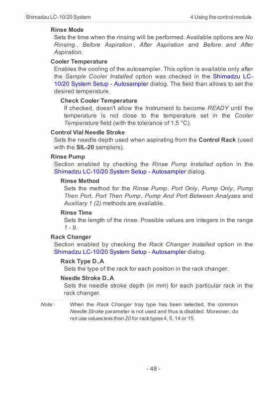
4.3.2.1 Method Setup - AS - Sampler (SIL-10Axl)This sub-tab replaces the Sampler sub-tab when the SIL-10Axl sampler isconfigured on the Instrument. The majority of items in the dialog is thesame, the differing items are described below:
Fig 36: Method Setup - AS - Sampler (SIL-10Axl)
Caution: Due to the error in the MIMIC Libraries, SIL-10AXL sampler does notsupport the non-default rack types. OnlyS rack type should be used whileoperating this sampler fromClarity.
Check Cooler TemperatureWhile checked, the temperature set in the Cooler Temperature field isvalidated against the real cooler temperature. When both values don'tmatch, the Instrument will not become ready.Injection Compensation FactorThe value that is used to compensate the actual volume of differentinjectors. The specified Injection volume is multiplied by the InjectionCompensation Factor value to produce the real injection volume. Possiblevalues are 1.00 - 1.30, although usually the value 1.00 is used.
- 49 -
Shimadzu LC-10/20 System 4Using the controlmodule
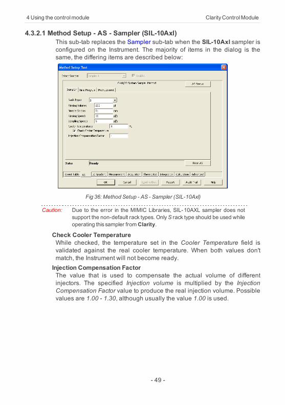
4.3.2.2 Method Setup - AS - Sampler (SIL-10AF)This sub-tab replaces the Sampler sub-tab when the SIL-10AF sampler isconfigured on the Instrument. The majority of items in the dialog is thesame, the differing items are described below:
Fig 37: Method Setup - AS - Sampler (SIL-10AF)
Excess VolumeAllows to set the excess volume of the sample drawn into the syringeduring each injection. This portion of the sample is not injected, but servesfor better precision of the injection. Allowed values in the Excess Volumefield are between 10 and 100 μl.Injection Compensation FactorThe value that is used to compensate the actual volume of differentinjectors. The specified Injection volume is multiplied by the InjectionCompensation Factor value to produce the real injection volume. Possiblevalues are 1.00 - 1.30, although usually the value 1.00 is used.
- 50 -
4 Using the controlmodule ClarityControlModule
4.3.3 Method Setup - AS - Time Program
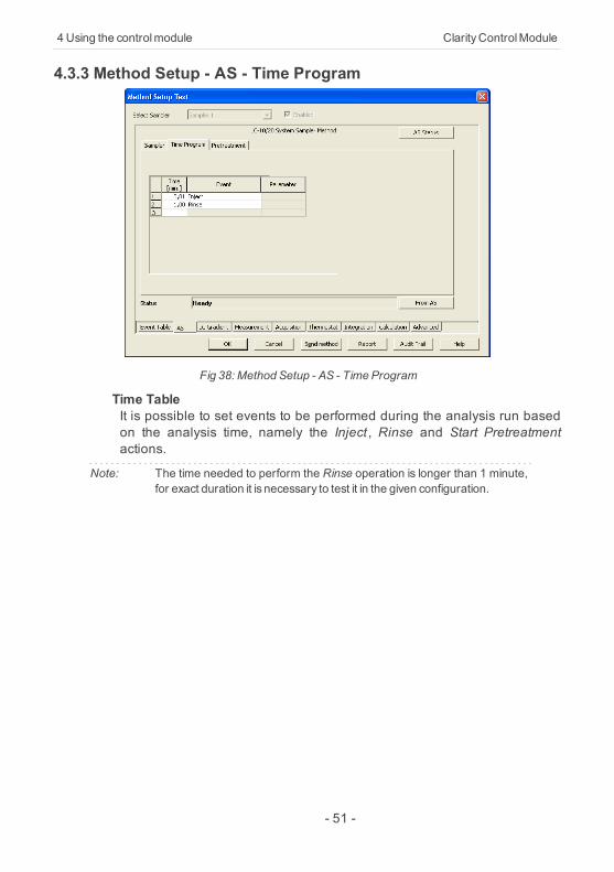
Fig 38: Method Setup - AS - Time Program
Time TableIt is possible to set events to be performed during the analysis run basedon the analysis time, namely the Inject , Rinse and Start Pretreatmentactions.
Note: The time needed to perform the Rinse operation is longer than 1 minute,for exact duration it is necessary to test it in the given configuration.
- 51 -
Shimadzu LC-10/20 System 4Using the controlmodule
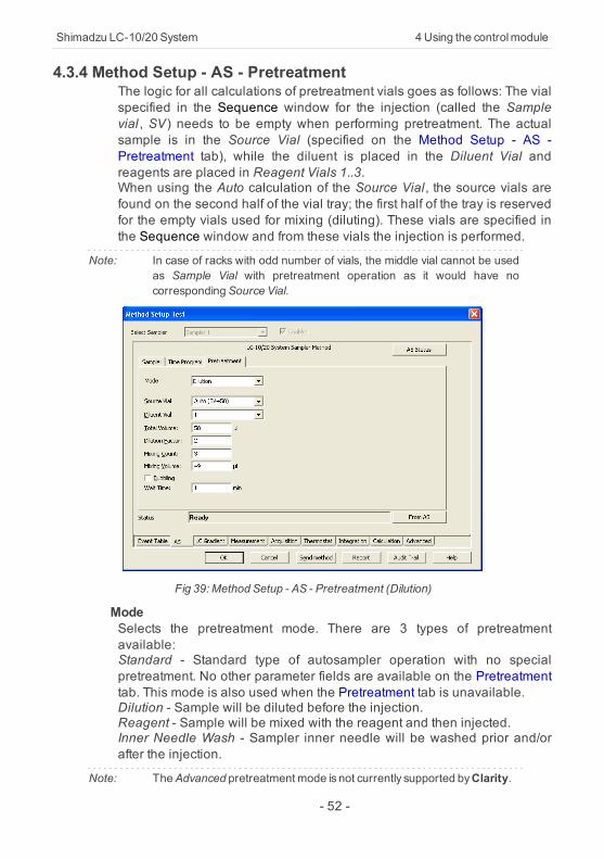
4.3.4 Method Setup - AS - PretreatmentThe logic for all calculations of pretreatment vials goes as follows: The vialspecified in the Sequence window for the injection (called the Samplevial , SV) needs to be empty when performing pretreatment. The actualsample is in the Source Vial (specified on the Method Setup - AS -Pretreatment tab), while the diluent is placed in the Diluent Vial andreagents are placed in Reagent Vials 1..3.When using the Auto calculation of the Source Vial, the source vials arefound on the second half of the vial tray; the first half of the tray is reservedfor the empty vials used for mixing (diluting). These vials are specified inthe Sequence window and from these vials the injection is performed.
Note: In case of racks with odd number of vials, the middle vial cannot be usedas Sample Vial with pretreatment operation as it would have nocorrespondingSource Vial.
Fig 39: Method Setup - AS - Pretreatment (Dilution)
ModeSelects the pretreatment mode. There are 3 types of pretreatmentavailable:Standard - Standard type of autosampler operation with no specialpretreatment. No other parameter fields are available on the Pretreatmenttab. This mode is also used when the Pretreatment tab is unavailable.Dilution - Sample will be diluted before the injection.Reagent - Sample will be mixed with the reagent and then injected.Inner Needle Wash - Sampler inner needle will be washed prior and/orafter the injection.
Note: TheAdvanced pretreatment mode is not currently supported byClarity.
- 52 -
4 Using the controlmodule ClarityControlModule
The set of other parameters available differ according to the Modeselected.
DilutionSource VialSpecifies the source vial for the original sample (before dilution).
Note: The vial used for dilution and injection is specified in the Sequencewindow.
Diluent VialSpecifies the vial from which the diluent (solvent) will be taken.Total VolumeSpecifies the final volume of the diluted sample without the respect to thevolume contraction.Dilution FactorSpecifies the factor for the dilution. For example, the factor 5 means thatthe resulting diluted sample will consist of 1/5 of pure sample and 4/5 ofdiluent.Mixing CountSpecifies the number of mixing cycles the dilution will consist of (range 1 -10 cycles).Mixing VolumeSpecifies the volume to be aspirated and flushed back in every mixingstep. This volume must be lower than the Total Volume.BubblingWhen checked, a bubble is aspirated during the mixing cycle in additionto the specified volume. The bubble is dispensed into the vial duringmixing.Wait TimeSets the time interval from the last mixing cycle to the injection. Possiblevalues are 0.1 - 120 minutes.
- 53 -
Shimadzu LC-10/20 System 4Using the controlmodule
Reagent
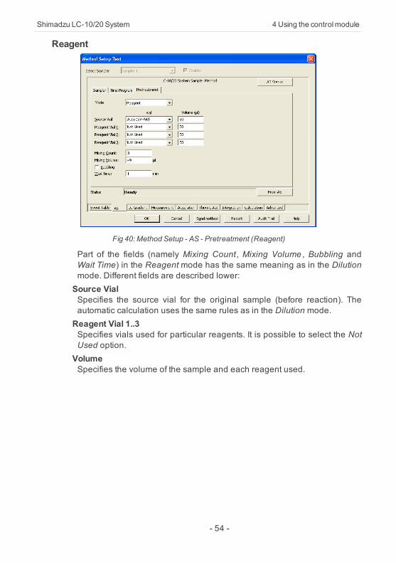
Fig 40: Method Setup - AS - Pretreatment (Reagent)
Part of the fields (namely Mixing Count, Mixing Volume , Bubbling andWait Time) in the Reagent mode has the same meaning as in the Dilutionmode. Different fields are described lower:Source VialSpecifies the source vial for the original sample (before reaction). Theautomatic calculation uses the same rules as in the Dilution mode.Reagent Vial 1..3Specifies vials used for particular reagents. It is possible to select the NotUsed option.VolumeSpecifies the volume of the sample and each reagent used.
- 54 -
4 Using the controlmodule ClarityControlModule
Inner Needle Wash
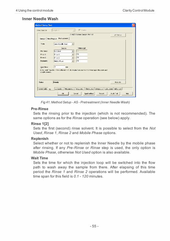
Fig 41: Method Setup - AS - Pretreatment (Inner NeedleWash)
Pre-RinseSets the rinsing prior to the injection (which is not recommended). Thesame options as for the Rinse operation (see below) apply.Rinse 1[2]Sets the first (second) rinse solvent. It is possible to select from the NotUsed, Rinse 1, Rinse 2 and Mobile Phase options.ReplenishSelect whether or not to replenish the Inner Needle by the mobile phaseafter rinsing. If any Pre-Rinse or Rinse step is used, the only option isMobile Phase, otherwise Not Used option is also available.Wait TimeSets the time for which the injection loop will be switched into the flowpath to wash away the sample from there. After elapsing of this timeperiod the Rinse 1 and Rinse 2 operations will be performed. Availabletime span for this field is 0.1 - 120 minutes.
- 55 -
Shimadzu LC-10/20 System 4Using the controlmodule
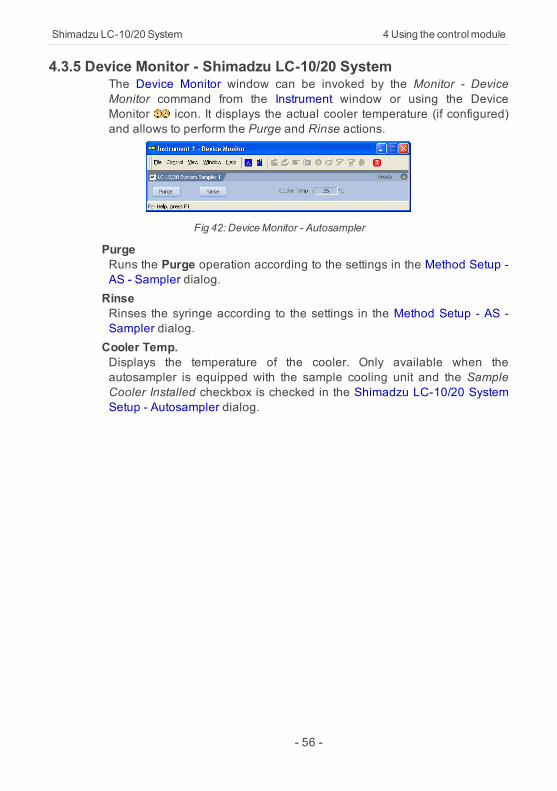
4.3.5 Device Monitor - Shimadzu LC-10/20 SystemThe Device Monitor window can be invoked by the Monitor - DeviceMonitor command from the Instrument window or using the DeviceMonitor icon. It displays the actual cooler temperature (if configured)and allows to perform the Purge and Rinse actions.
Fig 42: DeviceMonitor - Autosampler
PurgeRuns the Purge operation according to the settings in the Method Setup -AS - Sampler dialog.RinseRinses the syringe according to the settings in the Method Setup - AS -Sampler dialog.Cooler Temp.Displays the temperature of the cooler. Only available when theautosampler is equipped with the sample cooling unit and the SampleCooler Installed checkbox is checked in the Shimadzu LC-10/20 SystemSetup - Autosampler dialog.
- 56 -
4 Using the controlmodule ClarityControlModule
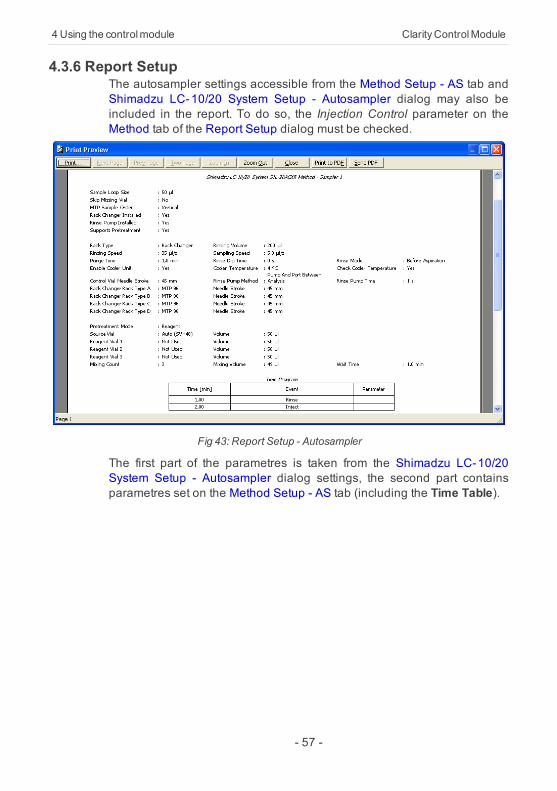
4.3.6 Report SetupThe autosampler settings accessible from the Method Setup - AS tab andShimadzu LC-10/20 System Setup - Autosampler dialog may also beincluded in the report. To do so, the Injection Control parameter on theMethod tab of the Report Setup dialog must be checked.
Fig 43: Report Setup - Autosampler
The first part of the parametres is taken from the Shimadzu LC-10/20System Setup - Autosampler dialog settings, the second part containsparametres set on the Method Setup - AS tab (including the Time Table).
- 57 -
Shimadzu LC-10/20 System 4Using the controlmodule
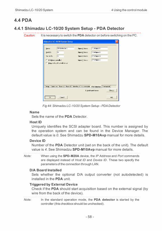
4.4 PDA4.4.1 Shimadzu LC-10/20 System Setup - PDA Detector
Caution: It is necessary to switch thePDA detector on before switching on the PC.
Fig 44: Shimadzu LC-10/20 SystemSetup - PDADetector
NameSets the name of the PDA Detector.Host IDUniquely identifies the SCSI adapter board. This number is assigned bythe operation system and can be found in the Device Manager. Thedefault value is 0. See Shimadzu SPD-M10Avpmanual for more details.Device IDNumber of the PDA Detector unit (set on the back of the unit). The defaultvalue is 4. See Shimadzu SPD-M10Avpmanual for more details.
Note: When using the SPD-M20A device, the IP Address and Port commandsare displayed instead of Host ID and Device ID . These two specify theparameters of the connection through LAN.
D/A Board InstalledSets whether the optional D/A output converter (not autodetected) isinstalled in the PDA unit.Triggered by External DeviceCheck if the PDA should start acquisition based on the external signal (bywire from the back of the device).
Note: In the standard operation mode, the PDA detector is started by thecontroller (this checkbox should be unchecked).
- 58 -

4 Using the controlmodule ClarityControlModule
Signal 1 (..4) NameDefines the names of the particular detector signals.
- 59 -
Shimadzu LC-10/20 System 4Using the controlmodule
4.4.2 Method Setup - PDA
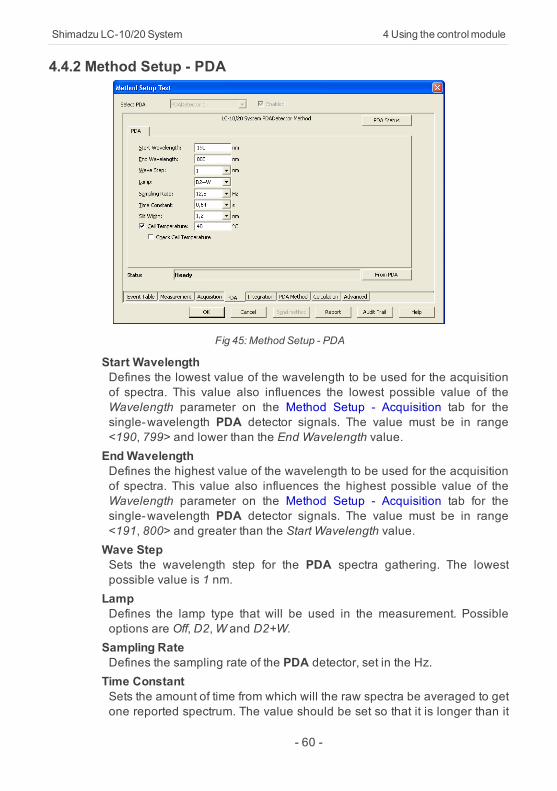
Fig 45: Method Setup - PDA
Start WavelengthDefines the lowest value of the wavelength to be used for the acquisitionof spectra. This value also influences the lowest possible value of theWavelength parameter on the Method Setup - Acquisition tab for thesingle-wavelength PDA detector signals. The value must be in range<190, 799> and lower than the End Wavelength value.EndWavelengthDefines the highest value of the wavelength to be used for the acquisitionof spectra. This value also influences the highest possible value of theWavelength parameter on the Method Setup - Acquisition tab for thesingle-wavelength PDA detector signals. The value must be in range<191, 800> and greater than the Start Wavelength value.Wave StepSets the wavelength step for the PDA spectra gathering. The lowestpossible value is 1 nm.LampDefines the lamp type that will be used in the measurement. Possibleoptions are Off, D2,W and D2+W.Sampling RateDefines the sampling rate of the PDA detector, set in the Hz.Time ConstantSets the amount of time from which will the raw spectra be averaged to getone reported spectrum. The value should be set so that it is longer than it
- 60 -

4 Using the controlmodule ClarityControlModule
takes to gather one spectrum (based on the Sampling Rate parameter).Slit WidthDefines the wavelength accuracy provided by the hardware.Cell TemperatureSets the temperature of the detector cell.Check Cell TemperatureWhen checked, the Instrument will not be ready until the actualtemperature will reach the set value (with the 1.5 °C tolerance). While thecheckbox is unchecked, no temperature verification will be performed.
- 61 -
Shimadzu LC-10/20 System 4Using the controlmodule
4.4.3 Method Setup - Acquisition
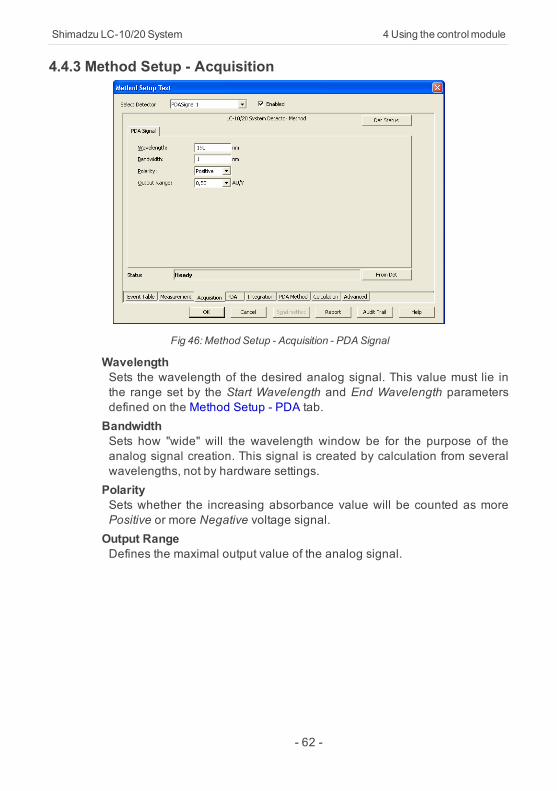
Fig 46: Method Setup - Acquisition - PDASignal
WavelengthSets the wavelength of the desired analog signal. This value must lie inthe range set by the Start Wavelength and End Wavelength parametersdefined on the Method Setup - PDA tab.BandwidthSets how "wide" will the wavelength window be for the purpose of theanalog signal creation. This signal is created by calculation from severalwavelengths, not by hardware settings.PolaritySets whether the increasing absorbance value will be counted as morePositive or more Negative voltage signal.Output RangeDefines the maximal output value of the analog signal.
- 62 -
4 Using the controlmodule ClarityControlModule
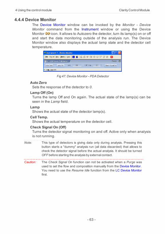
4.4.4 Device MonitorThe Device Monitor window can be invoked by the Monitor - DeviceMonitor command from the Instrument window or using the DeviceMonitor icon. It allows to Autozero the detector, turn its lamp(s) on or offand start the data monitoring outside of the analysis run. The DeviceMonitor window also displays the actual lamp state and the detector celltemperature.
Fig 47: DeviceMonitor - PDADetector
Auto ZeroSets the response of the detector to 0.Lamp Off (On)Turns the lamp Off and On again. The actual state of the lamp(s) can beseen in the Lamp field.LampShows the actual state of the detector lamp(s).Cell Temp.Shows the actual temperature on the detector cell.Check Signal On (Off)Turns the detector signal monitoring on and off. Active only when analysisis not running.
Note: This type of detectors is giving data only during analysis. Pressing thisbutton starts a "dummy" analysis run (all data discarded) that allows tocheck the detector signal before the actual analysis. It should be turnedOFF before starting the analysis byexternal contact.
Caution: The Check Signal On function can not be activated when a Purge wasused to set the flow and composition manually from the Device Monitor.You need to use the Resume Idle function from the LC Device Monitorfirst.
- 63 -
Shimadzu LC-10/20 System 4Using the controlmodule
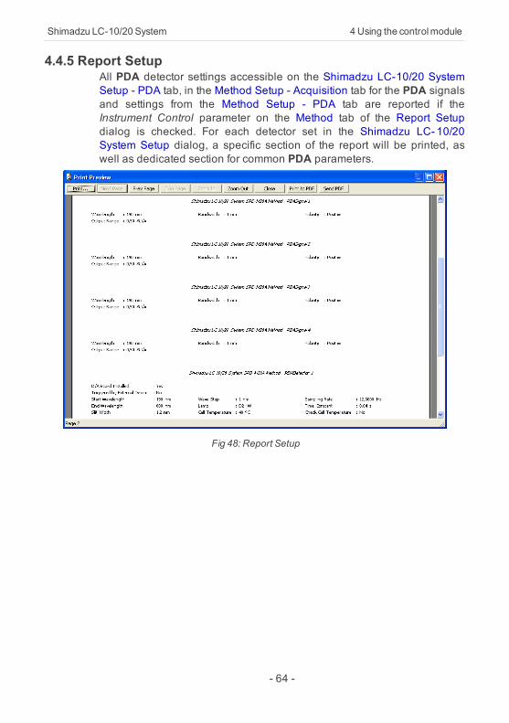
4.4.5 Report SetupAll PDA detector settings accessible on the Shimadzu LC-10/20 SystemSetup - PDA tab, in the Method Setup - Acquisition tab for the PDA signalsand settings from the Method Setup - PDA tab are reported if theInstrument Control parameter on the Method tab of the Report Setupdialog is checked. For each detector set in the Shimadzu LC- 10/20System Setup dialog, a specific section of the report will be printed, aswell as dedicated section for common PDA parameters.
Fig 48: Report Setup
- 64 -
4 Using the controlmodule ClarityControlModule
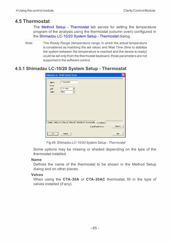
4.5 ThermostatThe Method Setup - Thermostat tab serves for setting the temperatureprogram of the analysis using the thermostat (column oven) configured inthe Shimadzu LC-10/20 System Setup - Thermostat dialog.
Note: The Ready Range (temperature range, in which the actual temperatureis considered as matching the set value) andWait Time (time to stabilizethe system between the temperature is reached and the device is ready)could be set only from the thermostat keyboard, those parameters are notsupported in the software control.
4.5.1 Shimadzu LC-10/20 System Setup - Thermostat
Fig 49: Shimadzu LC-10/20 SystemSetup - Thermostat
Some options may be missing or shaded depending on the type of thethermostat installed.NameDefines the name of the thermostat to be shown in the Method Setupdialog and on other places.ValvesWhen using the CTA-20A or CTA-20AC thermostat, fill in the type ofvalves installed (if any).
- 65 -
Shimadzu LC-10/20 System 4Using the controlmodule
4.5.2 Method Setup - Thermostat - Thermostat
Fig 50: Method Setup - Thermostat - Thermostat
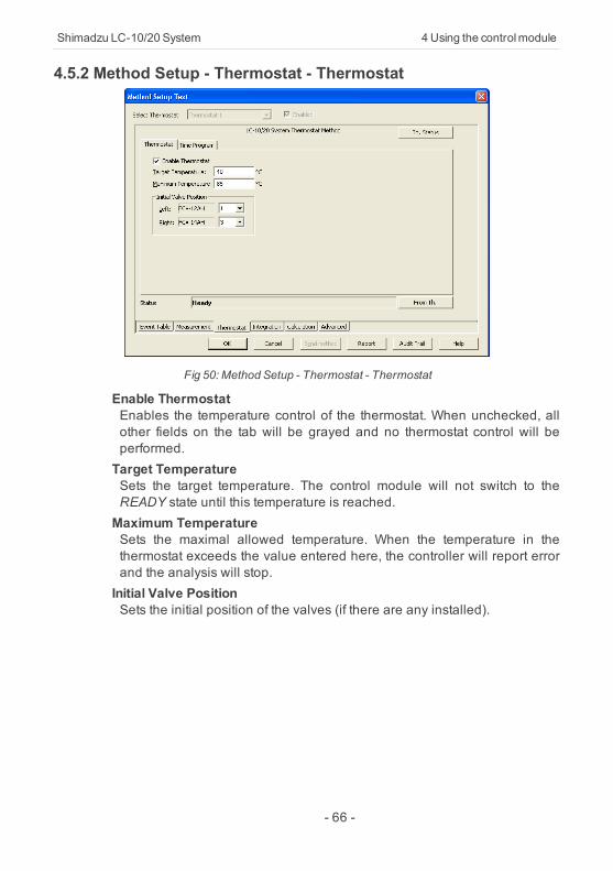
Enable ThermostatEnables the temperature control of the thermostat. When unchecked, allother fields on the tab will be grayed and no thermostat control will beperformed.Target TemperatureSets the target temperature. The control module will not switch to theREADY state until this temperature is reached.Maximum TemperatureSets the maximal allowed temperature. When the temperature in thethermostat exceeds the value entered here, the controller will report errorand the analysis will stop.Initial Valve PositionSets the initial position of the valves (if there are any installed).
- 66 -
4 Using the controlmodule ClarityControlModule
4.5.3 Method Setup - Thermostat - Time Program
Fig 51: Method Setup - Thermostat - Time Program
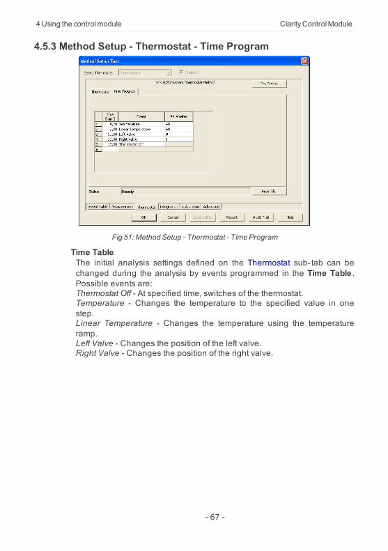
Time TableThe initial analysis settings defined on the Thermostat sub-tab can bechanged during the analysis by events programmed in the Time Table .Possible events are:Thermostat Off - At specified time, switches of the thermostat.Temperature - Changes the temperature to the specified value in onestep.Linear Temperature - Changes the temperature using the temperatureramp.Left Valve - Changes the position of the left valve.Right Valve - Changes the position of the right valve.
- 67 -
Shimadzu LC-10/20 System 4Using the controlmodule
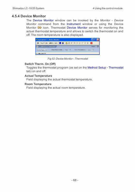
4.5.4 Device MonitorThe Device Monitor window can be invoked by the Monitor - DeviceMonitor command from the Instrument window or using the DeviceMonitor icon. Thermostat Device Monitor serves for monitoring theactual thermostat temperature and allows to switch the thermostat on andoff. The room temperature is also displayed.
Fig 52: DeviceMonitor - Thermostat
Switch Therm. On (Off)Toggles the thermostat program (as set on the Method Setup - Thermostattab) on and off.Actual TemperatureField displaying the actual thermostat temperature.Room TemperatureField displaying the actual room temperature.
- 68 -
4 Using the controlmodule ClarityControlModule
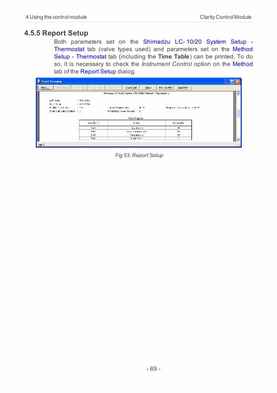
4.5.5 Report SetupBoth parameters set on the Shimadzu LC- 10/20 System Setup -Thermostat tab (valve types used) and parameters set on the MethodSetup - Thermostat tab (including the Time Table) can be printed. To doso, it is necessary to check the Instrument Control option on the Methodtab of the Report Setup dialog.
Fig 53: Report Setup
- 69 -
Shimadzu LC-10/20 System 5 Troubleshooting
5 Troubleshooting
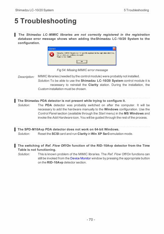
▌ The Shimadzu LC-MIMIC libraries are not correctly registered in the registrationdatabase error message shows when adding theShimadzu LC-10/20 System to theconfiguration.
Fig 54: MissingMIMIC error message
Description: MIMIC libraries (needed by the controlmodule) were probably not installed.Solution:To be able to use the Shimadzu LC-10/20 System control module it is
necessary to reinstall the Clarity station. During the installation, theCustom installationmust be chosen.
▌ The Shimadzu PDA detector is not present while trying to configure it.Solution: The PDA detector was probably switched on after the computer. It will be
necessary to add the hardware manually to the Windows configuration. Use theControl Panel section (available through the Startmenu) in theMS Windows andinvoke theAddHardware icon. You will be guided through the rest of the process.
▌ The SPD-M10Avp PDA detector does not work on 64-bit Windows.Solution: Reset theSCSI card and runClarity inWin XP Ser3 emulationmode.
▌ The switching of Ref. Flow Off/On function of the RID-10Avp detector from the TimeTable is not functioning.Solution: This is known problem of the MIMIC libraries. The Ref. Flow Off/On functions can
still be invoked from the Device Monitor window by pressing the appropriate buttonon theRID-10Avp detector section.
- 70 -
Shimadzu LC-10/20 System 6 VialPlate Numbers
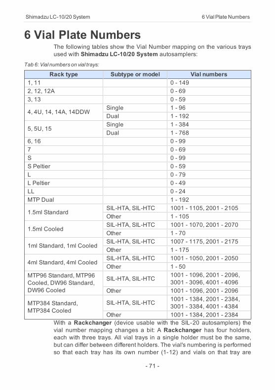
6 Vial Plate NumbersThe following tables show the Vial Number mapping on the various traysused with Shimadzu LC-10/20 System autosamplers:
Tab 6: Vial numberson vial trays:
Rack type Subtype or model Vial numbers1, 11 0 - 1492, 12, 12A 0 - 693, 13 0 - 59
4, 4U, 14, 14A, 14DDWSingle 1 - 96Dual 1 - 192
5, 5U, 15Single 1 - 384Dual 1 - 768
6, 16 0 - 997 0 - 69S 0 - 99S Peltier 0 - 59L 0 - 79L Peltier 0 - 49LL 0 - 24MTP Dual 1 - 192
1.5ml StandardSIL-HTA, SIL-HTC 1001 - 1105, 2001 - 2105Other 1 - 105
1.5ml CooledSIL-HTA, SIL-HTC 1001 - 1070, 2001 - 2070Other 1 - 70
1ml Standard, 1ml CooledSIL-HTA, SIL-HTC 1007 - 1175, 2001 - 2175Other 1 - 175
4ml Standard, 4ml CooledSIL-HTA, SIL-HTC 1001 - 1050, 2001 - 2050Other 1 - 50
MTP96 Standard, MTP96Cooled, DW96 Standard,DW96 Cooled
SIL-HTA, SIL-HTC 1001 - 1096, 2001 - 2096,3001 - 3096, 4001 - 4096
Other 1001 - 1096, 2001 - 2096
MTP384 Standard,MTP384 Cooled
SIL-HTA, SIL-HTC 1001 - 1384, 2001 - 2384,3001 - 3384, 4001 - 4384
Other 1001 - 1384, 2001 - 2384With a Rackchanger (device usable with the SIL-20 autosamplers) thevial number mapping changes a bit: A Rackchanger has four holders,each with three trays. All vial trays in a single holder must be the same,but can differ between different holders. The vial's numbering is performedso that each tray has its own number (1-12) and vials on that tray are
- 71 -

6 VialPlate Numbers ClarityControlModule
numbered according to the tray number multiplied by 1000 and the vialposition on that tray (based on the tray type):
Tab 7: Vial numbers in the Rackchanger:
Tray type Vial numbersMTP96, DWP96 1001 - 1096, 2001 - 2096, ..., 12001 - 12096MTP384, DWP384 1001 - 1384, 2001 - 2384, ..., 12001 - 123841.5ml Standard, 1.5ml Cooled 1001 - 1054, 2001 - 2054, ..., 12001 - 12054
The Control Rack used on SIL-20 autosamplers has vials numbered20001 - 20010.
- 72 -