Embed Size (px)
Citation preview

HITACHI PRIMAIDE
Clarity Control Module ENG
Code/Rev.: M183/70HDate: 24.10.2017
Phone: +420251013400 DataApex Ltd.
Fax: +420251013401 Petrzilkova 2583/13
[email protected] 15800Prague 5
www.dataapex.com TheCzech Republic

Clarity® , DataApex® and ® are trademarks of DataApex Ltd. Microsoft® and WindowsTM aretrademarks of Microsoft Corporation.DataApex reserves the right to make changes to manuals without prior notice. Updated manuals can bedownloaded fromwww.dataapex.com.
Author: MP

HitachiPrimaide Table of Contents
Contents1 Hitachi Primaide Control module 12 Requirements 23 Installation procedure 33.1 Hitachi Primaide communication 33.2 ClarityVA Configuration 4
4 Using the control module 74.1 Primaide Setup - Common 74.2 Pump 94.2.1 Primaide Setup - Pump 94.2.2 Method Setup - LC Gradient 104.2.2.1 Gradient Options 13
4.2.3 Method Setup - LC 144.2.4 Device Monitor 164.2.5 Report Setup 18
4.3 Autosampler 194.3.1 Hitachi Primaide Setup - Autosampler 194.3.2 Method Setup - AS 204.3.3 Device Monitor 234.3.4 Report Setup 25
4.4 Column Oven 264.4.1 Hitachi Primaide Setup - Column Oven 264.4.2 Method Setup - Thermostat 274.4.3 Device Monitor 284.4.4 Report Setup 29
4.5 PDA Detector 304.5.1 Hitachi Primaide Setup - PDA Detector 304.5.2 Method Setup - PDA - Detector Settings 314.5.3 Device Monitor 334.5.4 Report Setup 35
4.6 UV Detector 364.6.1 Hitachi Primaide Setup - UV Detector 364.6.2 Method Setup - Acquisition - Detector Settings 374.6.3 Method Setup - Acquisition - Time Program 384.6.4 Device Monitor 404.6.5 Report Setup 42
5 Troubleshooting 435.1 Primaide Maintenance Software 44
- i -

Table of Contents ClarityControlModule
To facilitate the orientation in the Hitachi Primaide manual and ClarityVA chromatographystation, different fonts are used throughout themanual. Meanings of these fonts are:
Instrument (blue text) marks the nameof thewindow to which the text refers.OpenFile (italics) describes the commands and names of fields in ClarityVA, parameters thatcan be entered into them or a window or dialog name (when you already are in the topicdescribing thewindow).WORK1 (capitals) indicates the nameof the file and/or directory.ACTIVE (capital italics) marks the state of the station or its part.
The bold text is sometimes also used for important parts of the text and the name of the ClarityVAstation. Moreover, some sections are written in format other than normal text. These sections areformatted as follows:
Note: Notifies the reader of relevant information.
Caution: Warns the user of possibly dangerous or very importantinformation.
▌ Marks the problem statement or trouble question.Description: Presents more detailed information on the problem, describes its causes,
etc.Solution: Marks the response to the question, presents a procedure how to remove it.
- ii -

HitachiPrimaide 1 HitachiPrimaide Controlmodule
1 Hitachi Primaide Control moduleThis manual describes the setting of the Hitachi Primaide HPLC system.The control module enables direct control of the instrument over the USBport.
Fig 1: HitachiPrimaide
This control module operates the whole system (including pumps,detectors, autosampler, column ovens, etc.). Direct control means that thesystem can be completely controlled from the ClarityVA environment.Instrument method controlling the analysis conditions will be saved in themeasured chromatograms.
ClarityVA can currently control the following modules:
Pump: 1110Detectors: 1410 UV, 1430 PDAAutosampler: 1210Column Oven: 1310
The number of controlled modules continues to extend, for up to date listsee the web site www.dataapex.com.
- 1 -
HitachiPrimaide 2 Requirements
2 RequirementsClarityVA installation DVD-ROM with LC control module (p/n A24)allowed. Other parts of the system may need other modules or extensions,namely the autosampler will need the AS control module (p/n A26) andthe PDA detector will need the PDA Extension (p/n A29).The control of Hitachi Primaide is available only in selected territories.Please contact us for details.
Note: Cablesare not part of theClarityVAControlModule. If you don't have theUSB cable for connecting the Interface Board with the PC, you can orderit as p/n SK06.
Caution: USB-IF Board supplied by the systemmanufacturer must be installed inone of the modules (usually the autosampler). This board is connected tothe computer over the USBport.
Caution: In case that system does not contain neither autosampler nor anydetector controlled via this controlmodule, it is necessary to use a specialcable (e-DIOcable, art.no. 890-6145) for start synchronization. With thiscable, it is possible either to propagate the start signal from other deviceon the Instrument or contrarily propagate the start signal from the HPLCsystem to other device.
Caution: TheHitachiPrimaide LC control for OpenLab/EZChrom and for ClarityVAmust not be installed on the same computer as it may result incommunication errors.
- 2 -
HitachiPrimaide 3 Installation procedure
3 Installation procedure3.1 Hitachi Primaide communication
It is possible to control up to 2 Hitachi Primaide systems configured ondifferent Instruments in the ClarityVA Chromatography Station. Then it isnecessary to set the switch on the first USB-IF Board to Sys1 , the secondone to the Sys2. Consult the USB-IF Boardmanual.It is also possible to connect up to 2 detectors on one Instrument. In caseone of the two detectors is not the Diode Array Detector , then it isnecessary to set different channel number for each of them in the HitachiPrimaide system and also in the Add Module dialog when configuring theHitachi Primaide in ClarityVA.
- 3 -

3 Installation procedure ClarityControlModule
3.2 ClarityVA Configuration
Fig 2: Adding HitachiPrimaidemodule
Press the Add button ① in the System Configuration dialog to invoke theAvailable Control Modules dialog.You can use the filter② to simplify the searching of the control module.
- 4 -

HitachiPrimaide 3 Installation procedure
Select the Hitachi Primaide and click the Add ③ button. The PrimaideSetup dialog will appear.
Fig 3: HitachiPrimaide Setup
Select the corresponding USB Interface Board and click the Autodetectbutton to detect all modules including their Serial and Program Numbers .Alternatively you can click the Add… button and add the availablemodules manually. Each module will add its own tab to the HitachiPrimaide Setup dialog. It will be described in the manual later. When youuse two detectors in one system, it is required to change the channelnumber of one of them. In case there are more systems controlled by thesame ClarityVA station, each of them must have different number of USBInterface Board . This number can be changed using a switch on thesystem's communication board.
After clicking the OK button, the Hitachi Primaide item ④ will appear inthe Setup Control Modules list of the System Configuration dialog.Set the Instrument Type on the desired Instrument tab ⑤ to LC.Drag the LC chromatograph icon from the Setup Control Modules list onthe left side to the desired Instrument tab ⑤ on the right side ⑥ , or use the
button ⑦ to do so.Set the digital input nr.1 to be used for starting the acquisition ⑧ . In casethere is no detector within the system, acquisition has to be started bydigital input of some other device (A/D converter or other device providingdigital inputs available in software). The eDIO cable is used to provide thestart marker signal. The Ext.Start Dig. Input needs to be set to therespective device digital input. The same cable needs to be used whenthe system does not include autosampler and an external contact (manual
- 5 -

3 Installation procedure ClarityControlModule
valve) is to be used for start. The Ext.Start Dig. Input needs to be set toDevice Primaide and Number 1.
- 6 -

HitachiPrimaide 4 Using the controlmodule
4 Using the control moduleSeveral new tabs appear in the Method Setup dialog, based on thesettings performed in the Primaide Setup dialog. These new tabs enablethe setting of the Hitachi Primaide system operation program.
Note: The instrument method is always sent to the Hitachi Primaide as awhole.
4.1 Primaide Setup - CommonThe Common tab serves for configuration of the communication with theHitachi Primaide system and for adding its modules you want to control.
Fig 4: Primaide Setup - Common tab
USB Interface BoardDepending on the switch configured on the USB-IF Board in the HitachiPrimaide system, this option allows to select the matching Sys1..4 setting.List of ModulesDisplays the list of modules autodetected or manually added to the setup.AutodetectWhen used, this button automatically detects modules and their serial andprogram numbers installed in your Hitachi Primaide system and liststhem in the List of Modules section.
- 7 -
4 Using the controlmodule ClarityControlModule
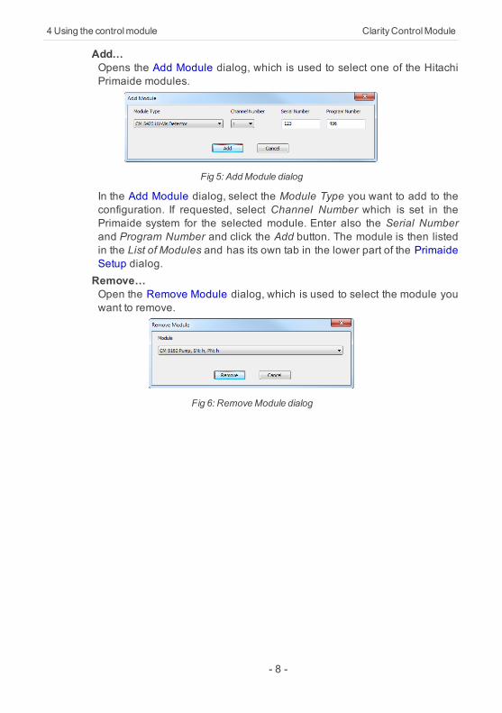
Add…Opens the Add Module dialog, which is used to select one of the HitachiPrimaide modules.
Fig 5: AddModule dialog
In the Add Module dialog, select the Module Type you want to add to theconfiguration. If requested, select Channel Number which is set in thePrimaide system for the selected module. Enter also the Serial Numberand Program Number and click the Add button. The module is then listedin the List of Modules and has its own tab in the lower part of the PrimaideSetup dialog.Remove…Open the Remove Module dialog, which is used to select the module youwant to remove.
Fig 6: RemoveModule dialog
- 8 -

HitachiPrimaide 4 Using the controlmodule
4.2 PumpThe Method Setup - LC Gradient tab serves for setting the gradients of thepumps configured in the Hitachi Primaide Setup - Pump dialog.
4.2.1 Primaide Setup - PumpThis tab of the Primaide Setup dialog allows to set the parameters of thepump. For details, see the manual of the pump.
Fig 7: Primaide Setup - Pump
Module TypeDisplays the Module Type you have added.Serial NumberDisplays the Serial Number you have entered for the module.Program NumberDisplays the Program Number you have entered for the module.Low Pressure LimitLower pressure limit. Number entered will be sent to the pump andchecked by the pump firmware.High Pressure LimitUpper pressure limit. Number entered will be sent to the pump andchecked by the pump firmware.Solvent 1 (...4) NameChange names for the particular solvent.Pump Off at Instrument CloseTurn off the pump when the Instrument is closed.
- 9 -

4 Using the controlmodule ClarityControlModule
4.2.2 Method Setup - LC GradientThe Method Setup - LC Gradient dialog serves for setting up the LCinstrument method.
Fig 8: Method Setup - LC Gradient
Gradient TableA table for setting the composition of the mobile phase and the overallflow rate as a function of time. Operation is analogous to that ofspreadsheets (Excel, Quatro Pro, etc.). To prepare the cell to receivevalues, click it by the left mouse button; the cell will highlight by dots. A cellthat fails to highlight is not available for editing.Time [min.]Sets the time at which the ratio of flow rates and the overall flow ratewill correspond to the values entered in the corresponding row. (Theflows change gradually from one time to the next in a manner ensuringthat the conditions specified in the next row will be satisfied).XXX1 (..4) [%]Represents the percentage of a component. The designation XXX1-4is in fact replaced by the name of the component (items Solvent 1 - 4in the Gradient Options dialog). Should you enter a component valuesuch that the sum of all values exceeds 100 %, the percentage in thelast column will be automatically adjusted; if the percentage of the lastcompound is already zero, the value of the currently enteredcomponent is adjusted instead. The flow rate of a compound is
- 10 -

HitachiPrimaide 4 Using the controlmodule
calculated by multiplying the overall flow rate (indicated in the Flowcolumn) by the corresponding percentage divided by 100.Flow [ml/min]Indicates the overall flow rate through the column. The entered valueapplies to the time specified in the corresponding row.
Caution: The maximum flow may vary according to the pump type you haveinstalled. Check the pump's manual. Pump 5160 accepts maximum flowof 5.0ml/min.
GraphThe graph depicts the percentage of components as a function of timetogether with the overall flow rate. Data are taken over from the GradientTable . Changes effected in this table are immediately reflected in thegraph. Legend in the header of the graph indicates the assignment ofcolors to individual components. The assignment is fixed and individualcomponents are displayed in the graph from bottom to top. The flow rate isdisplayed as a black line.The graph has two vertical axes: the axis on the left refers to the mixingratio, the one on the right to the overall flow rate.Parameters
Standby FlowSets the overall flow rate through the column in the STANDBY statereached after the last row of the table has been performed and thetime period defined in the Time to Standby field has passed. Theduration of this state is defined by the Standby Time item. The ratio ofindividual components in the respective STANDBY and IDLE states isgiven by the first row of the Gradient Table (the Initial row).Time to Standby [min]Indicates the time during which the flow rate and mobile phasecomposition changes continuously between the last values entered inthe table and the values defined by the Standby Flow field and theInitial row mobile phase composition.This time is included in the analysis time (the Instrument is in theCONTROL state). In case when the Time to Standby is zero, there willbe steep change from the flow and components percentage specifiedon the last row of the gradient table to that specified for STANDBYstate.Standby Time [min]The time during which the flow rate is maintained at Standby Flow .This time is included in the analysis time (the Instrument is in theCONTROL state).
- 11 -

4 Using the controlmodule ClarityControlModule
Idle StateAn item specifying the overall flow rate through the column outside theinstrument method. The following options are possible:Pump OffThe flow rates of all components are zero.
Caution: Be careful as this settingmaydamage the column in some cases.
InitialThe flow rate is defined by the first row of the Gradient Table (theInitial row).StandbyThe flow rate is the same as in the STANDBY mode and, accordingly,corresponds to the value entered in Standby Flow field.Initial - StandbyNot supported by these pumps.
The IDLE state comes into effect each time an Instrument is opened, at theend or after abortion of an analysis by the Abort command, and is alsomaintained after the ClarityVA program is shut down.The mixing ratio of individual components in both the IDLE and STANDBYstates is given by the first row of the Gradient Table (the Initial row).
Note: There is a steep change in the flow and components percentage from thevalues specified for the STANDBY state to those specified for the IDLEstate if the Idle State field is not set toStandby.
- 12 -

HitachiPrimaide 4 Using the controlmodule
4.2.2.1 Gradient OptionsInvoke the Options... button in the Method Setup - LC Gradient dialog toopen the Gradient Options dialog. This dialog allows to set the customname for particular solvents, to set whether they are used or not in thegradient and to set the warning levels for pressure to prevent the damageto hardware.The above mentioned pressure limits are checked in the software.Pressure check for low pressure limit doesn't start immediately after pumpis started, but with few minutes delay. During this delay the pressure inchromatographic system can stabilize.In addition to Min. Pressure and Max. Pressure , there are pressure limitsset in the Primaide Setup - Pump dialog. Those limits are checked in thepump firmware. As they will cause a system error, they should be setoutside the limits defined here in the Gradient Options dialog.
Fig 9: Gradient Options
Min. PressureSets the minimum pressure for the given pump. When pressure drops tothe set value, the pump will shut down. This prevents the solvent leakage.Max. PressureSets the maximum pressure for the given pump. When pressure reachesthe set value, all pumps on the Instrument will shut down. This serves toprevent the damage to the pump when the column is blocked.
Note: Min. Pressure and Max. Pressure for the Hitachi Primaide pumps varyin certain range according to the type of the pump and valvesused. Checkthe devicemanual for valid values for your pump.
Solvent 1 (..4)It is possible to enable/disable particular solvent, as well as to set customname to it.
- 13 -

4 Using the controlmodule ClarityControlModule
4.2.3 Method Setup - LCThe Method Setup - LC dialog serves for setting the auxiliary parametersof the pump.
Fig 10: Method Setup - LC Gradient
Time ProgramTurns the using of Time Program on and off.Leak SensorTurns the using of Leak Sensor on and off.
- 14 -

HitachiPrimaide 4 Using the controlmodule
Method Setup - LC - Time ProgramThis section contains Time Program table, which serves for controlling theEvents (Digital outputs of the pump) during the analysis. For each row(time) it is possible to set the output to On, Off or Pulse. This table is activeonly with Time Program turned on.
Fig 11: Method Setup - LC - Time Program
- 15 -

4 Using the controlmodule ClarityControlModule
4.2.4 Device MonitorThe pump status dialog can be invoked by the Monitor - Device Monitor
command from the Instrument window. It displays the actual flows ofparticular solvents, as well as the total flow, the total pressure and theanalysis time.
Fig 12: LCMonitor
Stop FlowThe pumps can be stopped from this window using the Stop Flow button.This action will stop the pump only, the analysis run will continue andmust be stopped or aborted from the Data Acquisition window or SingleAnalysis dialog.PurgeThe pumps may be purged by pressing this button. Set the desired totalflow and solvent ratios in the opened Set Flow dialog.
Fig 13: Set Flow
Resume IdleReturns the pumps to IDLE state as defined in the appropriate field on theLC Gradient tab of the Method Setup dialog.Hold / ResumeNot supported by this pump.
- 16 -

HitachiPrimaide 4 Using the controlmodule
Manual Flow…Not supported by this pump.To display the HW Configuration dialog, use the Det. Status button on oneof the detector's Device Monitor.
- 17 -

4 Using the controlmodule ClarityControlModule
4.2.5 Report SetupAll of the pump settings accessible on the Method Setup - LC Gradient taband in the Gradient Options dialog are reported, if the pump is configuredas a part of the gradient. To do so, the Instrument Control parameter onthe Method tab of the Report Setup dialog must be checked.
Fig 14: Report - pump part of the gradient
- 18 -

HitachiPrimaide 4 Using the controlmodule
4.3 AutosamplerThe autosampler used with the Hitachi Primaide allows for automatedinjection of samples. This can only be performed from the Sequencewindow, not from the Single Analysis dialog (where it is impossible tospecify from which position the injection will be performed).
4.3.1 Hitachi Primaide Setup - Autosampler
Fig 15: Primaide Setup - Autosampler
Module TypeDisplays the Module Type you have added.Serial NumberDisplays the Serial number you have entered for the module.Program NumberDisplays the Program Number you have entered for the module.Sampler NameSets the name of the autosampler.Rack Properties
CodeSets the proper code of the rack.TypeSets the proper type of the rack.
Syringe TypeSets the proper type of the syringe depending on its volume.Loop CapacitySets the capacity of the loop.
- 19 -

4 Using the controlmodule ClarityControlModule
4.3.2 Method Setup - AS
Fig 16: Method Setup - AS
InjectionVial DetectionTurns on the detection of vials in the tray.Inj TimingTurns on the PASS function (Pump Autosampler Synchronisation). Forproper function the system must be equipped with model 5110 pumpwith minimal flow of 0,2 ml/min set.
SpeedSyringe InjectionSets the speed of the syringe during injection.Syringe WashSets the speed of the syringe during wash.Needle SpeedSets the speed of the needle.
Thermo UnitThis section is enabled, if the autosampler have installed the Thermo Unit.TemperatureSets the target temperature of the cooling.Use ToleranceSets whether to use the tolerance.
- 20 -

HitachiPrimaide 4 Using the controlmodule
ToleranceIf the Use Tolerance is checked, sets the tolerance.When vial is missingSets the behavior when the vial is missing.
- 21 -

4 Using the controlmodule ClarityControlModule
Washing + Leak SensorParameters used during the washing.
Fig 17: Method Setup - AS - Washing
Syringe Stroke Number at InjectionSets the number of times syringe is washed at the injection.Needle Washing TimeSets the Needle Washing Time.Pump Plunger Wash at Injection WashSets whether the Pump Plunger will be washed at Injection Wash. Thisfunction requires corresponding plumbing between autosampler andpump.Plunger Washing TimeSets the Plunger Washing Time.
- 22 -
HitachiPrimaide 4 Using the controlmodule
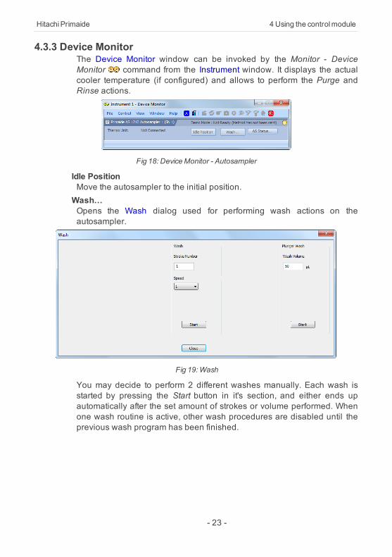
4.3.3 Device MonitorThe Device Monitor window can be invoked by the Monitor - DeviceMonitor command from the Instrument window. It displays the actualcooler temperature (if configured) and allows to perform the Purge andRinse actions.
Fig 18: DeviceMonitor - Autosampler
Idle PositionMove the autosampler to the initial position.Wash…Opens the Wash dialog used for performing wash actions on theautosampler.
Fig 19:Wash
You may decide to perform 2 different washes manually. Each wash isstarted by pressing the Start button in it's section, and either ends upautomatically after the set amount of strokes or volume performed. Whenone wash routine is active, other wash procedures are disabled until theprevious wash program has been finished.
- 23 -
4 Using the controlmodule ClarityControlModule
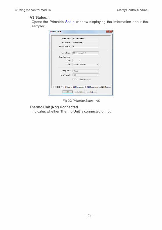
AS Status…Opens the Primaide Setup window displaying the information about thesampler.
Fig 20: Primaide Setup - AS
Thermo Unit (Not) ConnectedIndicates whether Thermo Unit is connected or not.
- 24 -

HitachiPrimaide 4 Using the controlmodule
4.3.4 Report SetupThe autosampler settings accessible from the Method Setup - AS tab andPrimaide Setup - Autosampler dialog may also be included in the report.To do so, the Injection Control parameter on the Method tab of the ReportSetup dialog must be checked.
Fig 21: Report - Autosampler
The first part of the parameters is taken from the Primaide Setup -Autosampler dialog settings, the second part contains parameters set onthe Method Setup - AS tab.
- 25 -
4 Using the controlmodule ClarityControlModule
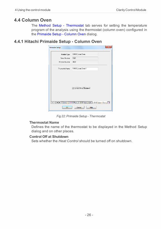
4.4 Column OvenThe Method Setup - Thermostat tab serves for setting the temperatureprogram of the analysis using the thermostat (column oven) configured inthe Primaide Setup - Column Oven dialog.
4.4.1 Hitachi Primaide Setup - Column Oven
Fig 22: Primaide Setup - Thermostat
Thermostat NameDefines the name of the thermostat to be displayed in the Method Setupdialog and on other places.Control Off at ShutdownSets whether the Heat Control should be turned off on shutdown.
- 26 -

HitachiPrimaide 4 Using the controlmodule
4.4.2 Method Setup - Thermostat
Fig 23: Method Setup - Thermostat
Target TemperatureSets the target temperature.Upper Limit TemperatureSets the maximal allowed temperature. When the temperature in thethermostat exceeds the value entered here, the controller will report errorand the analysis will stop.Temperature ToleranceThe control module will not switch to the READY state until the actualtemperature will not be in the temperature tolerance and the Wait Timehas elapsed.Wait TimeSets the time in min. until the Thermostat will report READY status.Valve PositionSets the initial position of the valves (if there are any installed).Leak SensorAllows to set the leak sensor on/off.
- 27 -

4 Using the controlmodule ClarityControlModule
4.4.3 Device MonitorThe Device Monitor window can be invoked by the Monitor - DeviceMonitor command from the Instrument window. Thermostat DeviceMonitor serves for monitoring the actual thermostat temperature andallows to switch the thermostat on and off.
Fig 24: DeviceMonitor - Thermostat
Oven TemperatureField displaying the actual oven temperature.Ambient TemperatureField displaying the actual ambient temperature.Current Wait TimeInformation about the actual wait time duration.Valve StatusInformation about the valve status. When acquisition is not running(between the analyses) it is possible to directly switch the state of thevalve.Switch On (Off)Turns the column oven on and off.
- 28 -

HitachiPrimaide 4 Using the controlmodule
Th. Status…Opens the Primaide Setup window displaying the information about thecolumn oven.
Fig 25: Primaide Setup - ColumnOven
4.4.4 Report SetupBoth parameters set on the Primaide Setup - Thermostat tab (valve typesused) and parameters set on the Method Setup - Thermostat tab can beprinted. To do so, it is necessary to check the Instrument Control option onthe Method tab of the Report Setup dialog.
Fig 26: Report - Thermostat
- 29 -

4 Using the controlmodule ClarityControlModule
4.5 PDA DetectorThe Method Setup - PDA tab and its sub-tabs serve for setting the PDADetector parameters configured in the Primaide Setup - PDA Detectordialog.
4.5.1 Hitachi Primaide Setup - PDA Detector
Fig 27: Primaide Setup - PDADetector
Module TypeDisplays the Module Type you have added.Serial NumberDisplays the Serial number you have entered for the module.Program NumberDisplays the Program Number you have entered for the module.Detector NameSets the name of the detector used through the software.Number of signalsSets the number of signals provided by the detectorSignal 1 (..4) NameSets the names of the signals acquired by the detector.Lamp Off at ShutdownSets whether the Lamp should be turned off on shutdown. Lamp could beturned on again by sending the method to the detector, in case it is set inthe method.
- 30 -

HitachiPrimaide 4 Using the controlmodule
4.5.2 Method Setup - PDA - Detector Settings
Fig 28: Method Setup - PDA
Sample PeriodSets the period time in ms. Valid values are 10, 20, 50, 100, 200, 400,800, 1600 and 3200 ms.
Note: If lower values are selected (e.g. 10 ms) lower filtering Response Timeshould be used (e.g. 0,01 s), otherwise the resulting chromatogram willnot be smooth.
LampModeSets the mode of the lamp. With None option set both lamps are turned offand detector stays in Not Ready state.SlitSets if the Slit is Coarse or Fine.Minimum WLSets the minimal wavelength for measurement.Maximum WLSets the maximal wavelength for measurement.Signal 1..4 WLSets the wavelength the detector will be measuring on each of theparticular signals.Check Lamp StatusIf Checked, the status of the lamp will be detected before run.
- 31 -

4 Using the controlmodule ClarityControlModule
BandwidthSets the bandwidth used for measurement.Response TimeSets the response time.Recorder RangeSets the Recorder Range. Active only with Analog Output Board installed.WL1 (WL2)Sets the wavelengths used for recorder output.Leak SensorAllows to set the leak sensor on/off.
- 32 -

HitachiPrimaide 4 Using the controlmodule
4.5.3 Device MonitorThe Device Monitor window can be invoked by the Monitor - DeviceMonitor command from the Instrument window. It displays the actualwavelength and also allows to perform the Zero Detector action andswitch the lamp on and off.
Fig 29: DeviceMonitor - PDADetector
It is possible to control the detector operation during the analysis in theDevice Monitor window.Zero DetectorSets the response of the detector to 0.Switch On (Off)Turns the D2 andWLamps on/off.Thermo Unit Not Connected/ OffIndicates whether Thermo Unit is connected or not.Check Signal Switch On/OffEnables to monitor baseline process besides the analysis.PDA Status…Opens the Primaide Setup window displaying the information about thedetector. On the bottom of the screen there are information about usagetime and number of ignitions of both lamps.
- 33 -

4 Using the controlmodule ClarityControlModule
Fig 30: Primaide Setup - Detector
Lamp Off at ShutdownTurns the lamp off after shutdown.LampMaintenanceOpens the UV Detector: Lamp Maintenance window displaying theinformation about the lamps.
Fig 31: LampMaintenance
ResetEnable to reset the lamp counter in case lamp has been changed.
- 34 -

HitachiPrimaide 4 Using the controlmodule
4.5.4 Report SetupAll detector settings accessible on the Method Setup - Acquisition tab(including sub-tabs) are reported if the Instrument Control parameter onthe Method tab of the Report Setup dialog is checked.
Fig 32: Report - PDADetector
Two groups of parameters will be then printed, one common to allchannels of a given detector, the other specific to particular channels.
- 35 -

4 Using the controlmodule ClarityControlModule
4.6 UV DetectorThe Method Setup - Acquisition tab and its sub-tabs serves for setting theUV Detector parameters configured in the Primaide Setup - UV Detectordialog.
4.6.1 Hitachi Primaide Setup - UV Detector
Fig 33: Primaide Setup - UVDetector
Module TypeDisplays the Module Type you have added.Serial NumberDisplays the Serial number you have entered for the module.Program NumberDisplays the Program Number you have entered for the module.Signal NameSets the name of the signal acquired by the detector.Lamp Off at ShutdownSets whether the Lamp should be turned off on shutdown. Lamp could beturned on again by sending the method to the detector, in case it is set inthe method.
- 36 -

HitachiPrimaide 4 Using the controlmodule
4.6.2 Method Setup - Acquisition - Detector Settings
Fig 34: Method Setup - Acquisition - Detector Settings
Sample PeriodSets the period time in ms. Valid values are 10, 20, 50, 100, 200, 400,800, 1600 and 3200 ms for single mode and 400, 800, 1600 and 3200 msfor dual mode.
Note: If lower values are selected (e.g. 10 ms) lower filtering Response Timeshould be used (e.g. 0,01 s), otherwise the resulting chromatogram willnot be smooth.
LampModeSets the mode of the lamp. With None option set the lamp is turned off.WL1 (WL2)Sets the wavelength the detector is measuring on.Time ProgramSets whether the Time Program is turned on/off. This option is availableonly whenWavelength Mode is set to Single.Check Lamp StatusIf Checked, the status of the lamp will be detected before run.Autozero at StartIf checked, reset of the detector will be performed before each start.Response TimeDefines the Time Constant of the detector's filter.
- 37 -

4 Using the controlmodule ClarityControlModule
Processor RangeSets the Processor Range.Leak SensorAllows to set the leak sensor on/off.
Caution: Even when the values are 0.25; 0.50; 1.00 and 2,00 AUFS, the actualProcessor Range is applied in double value than the selected one.
OffsetSets the offset of the signal output.PolaritySets whether the Polarity is positive/negative.Recorder RangeSets the Recorder Range. Active only with Analog Output Board installed.
4.6.3 Method Setup - Acquisition - Time ProgramTime Program allows to set the detector wavelength parameter defined onprevious tab based on the analysis time. It is available in Single WL modeonly. This tab is active only when Time Program is turned on Detector tab.In order to modify wavelength for desired time by the Time Program, thetable has to contain a row defining time when wavelength is about toswitch to new one and successive row (with the same wavelength as onprevious row) defining time interval for use of newly set wavelength. Whena last row of the table is reached the time program is finished and initialconditions are set according to wavelength defined in the method tab. IfTime Program is longer then Autostop time of the method the Instrumentwill in switch to Control after elapsing Autostop time.
- 38 -
HitachiPrimaide 4 Using the controlmodule
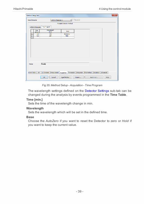
Fig 35: Method Setup - Acquisition - Time Program
The wavelength settings defined on the Detector Settings sub-tab can bechanged during the analysis by events programmed in the Time Table.Time [min.]Sets the time of the wavelength change in min.WavelengthSets the wavelength which will be set in the defined time.BaseChoose the AutoZero if you want to reset the Detector to zero or Hold ifyou want to keep the current value.
- 39 -

4 Using the controlmodule ClarityControlModule
4.6.4 Device MonitorThe Device Monitor window can be invoked by the Monitor - DeviceMonitor command from the Instrument window. It displays the actualwavelength and also allows to perform the Zero Detector action andswitch the lamp off.
Fig 36: DeviceMonitor - UVDetector
It is possible to control the detector operation during the analysis in theDevice Monitor window.Zero DetectorSets the response of the detector to 0.Switch On (Off)Turns the D2 Lamp on/off.WavelengthCurrent wavelength retrieved from the UV Detector.Abs DataAbsolute data retrieved from the UV Detector.Sample EnergySample energy retrieved from the UV Detector.Ref EnergyReference energy retrieved from the UV Detector.WL1 (WL2)Depending on theWavelength Mode indicates the values from Signal 1 orboth Signal 1 and 2.Thermo Unit Not Connected/ OffIndicates whether Thermo Unit is connected or not.Det Status…Opens the Primaide Setup window displaying the information about themodule.
- 40 -

HitachiPrimaide 4 Using the controlmodule
Fig 37: Primaide Setup - Detector
Lamp Off at ShutdownTurns the lamp off after shutdown.LampMaintenanceOpens the UV Detector: Lamp Maintenance window displaying theinformation about the lamps.
Fig 38: LampMaintenance
ResetEnable to reset the lamp counter in case lamp has been changed.
- 41 -
4 Using the controlmodule ClarityControlModule
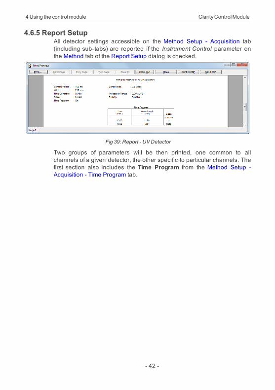
4.6.5 Report SetupAll detector settings accessible on the Method Setup - Acquisition tab(including sub-tabs) are reported if the Instrument Control parameter onthe Method tab of the Report Setup dialog is checked.
Fig 39: Report - UVDetector
Two groups of parameters will be then printed, one common to allchannels of a given detector, the other specific to particular channels. Thefirst section also includes the Time Program from the Method Setup -Acquisition - Time Program tab.
- 42 -

HitachiPrimaide 5 Troubleshooting
5 TroubleshootingWhen the remedy for some problem cannot be discovered easily, therecording of communication between ClarityVA and the chromatographcan significantly help to discover the cause of the problem.The recording can be enabled by adding or amending the COMMDRV.INIfile in the ClarityVA installation directory (C:\CLARITYVA\CFG by default).The file can be edited in any text editor (e.g. Notepad). Following sectionshould be edited or added:
[PRIMAIDE 1]echo=ontextmode=onfilename=Comm_Primaide_%D.txtreset=off
The created *.TXT files will greatly help in diagnosis of unrecognizederrors and problems in communication.
Note: In case your system uses other USB Interface Board than Sys 1, youshould change the number in the section header to the proper value.
▌It is not possible to start the Acquisition from ClarityVA when using the detectorwithout the included autosampler.Solution: When using the detector itself without internal autosampler, start theAcquisition by
the external start from your autosampler (set properly the Ext. Start Dig. Input ofthe detector in theClarityVAConfiguration).
▌It is not possible to start the Acquisition from ClarityVA when using the systemwithout the included detector.Solution: When used the system without internal detector, start the Acquisition by the
external start to the digital input of some other device connected to the ClarityVA(set properly Ext. Start Dig. Input of the device used in the ClarityVAConfiguration).
- 43 -

5 Troubleshooting ClarityControlModule
▌In case that communication between the computer and PM1430 DAD Detector getsfreezed, error message "Server Busy" occurs.Solution: In that case it is necessary to restart the detector, by turning it off and on again.
5.1 Primaide Maintenance SoftwareFor service purposes or setting of the Gas Leak Sensor install thePrimaide Maintanace Software located in C:\CLARITYVA\HW_DRIVERS\PRIMAIDEDRIVERKIT\TOOLS. This application can be alsoused for evaluation of communication troubles between ClarityVA andPrimaide system.
- 44 -


![HITACHI CAPITAL CORPORATION HITACHI … the purposes of Directive 2004/39/EC ... HITACHI CAPITAL CORPORATION HITACHI CAPITAL (UK) PLC HITACHI CAPITAL AMERICA CORP. [[] []](https://img.pdfslide.us/doc/110x75/5ad063b27f8b9a1d328e3da3/hitachi-capital-corporation-hitachi-the-purposes-of-directive-200439ec-.jpg)