Embed Size (px)
Citation preview
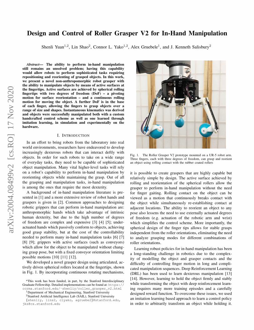
Design and Control of Roller Grasper V2 for In-Hand Manipulation
Shenli Yuan1,2, Lin Shao2, Connor L. Yako1,2, Alex Gruebele1, and J. Kenneth Salisbury2
Abstract— The ability to perform in-hand manipulationstill remains an unsolved problem; having this capabilitywould allow robots to perform sophisticated tasks requiringrepositioning and reorienting of grasped objects. In this work,we present a novel non-anthropomorphic robot grasper withthe ability to manipulate objects by means of active surfaces atthe fingertips. Active surfaces are achieved by spherical rollingfingertips with two degrees of freedom (DoF) – a pivotingmotion for surface reorientation – and a continuous rollingmotion for moving the object. A further DoF is in the baseof each finger, allowing the fingers to grasp objects over arange of size and shapes. Instantaneous kinematics was derivedand objects were successfully manipulated both with a customhandcrafted control scheme as well as one learned throughimitation learning, in simulation and experimentally on thehardware.
I. INTRODUCTION
In an effort to bring robots from the laboratory into realworld environments, researchers have endeavored to developincreasingly dexterous robots that can interact deftly withobjects. In order for such robots to take on a wide rangeof everyday tasks, they need to be capable of sophisticatedobject manipulation. Many vital higher-level tasks will relyon a robot’s capability to perform in-hand manipulation byreorienting objects while maintaining the grasp. Out of allthe grasping and manipulation tasks, in-hand manipulationis among the ones that require the most dexterity.
A background of in-hand manipulation literature is pre-sented in [1] and a more extensive review of robot hands andgraspers is given in [2]. Common approaches to designingrobotic grippers that can perform in-hand manipulation are:anthropomorphic hands which take advantage of intrinsichuman dexterity, but due to the high number of degreesof freedom are complex and expensive [3] [4] [5]; under-actuated hands which passively conform to objects, achievinggood grasp stability, but at the cost of the controllabilityneeded to perform many in-hand manipulation tasks [6] [7][8] [9]; grippers with active surfaces (such as conveyors)which allow for the object to be manipulated without chang-ing grasp pose, but with a fixed conveyor orientation limitingpossible motions [10] [11] [12].
We developed a novel grasper design using articulated, ac-tively driven spherical rollers located at the fingertips, shownin Fig. 1. By incorporating continuous rotating mechanisms,
*This work has been funded, in part, by the Stanford InterdisciplinaryGraduate Fellowship. Detailed implementations can be found at: https://ccrma.stanford.edu/˜shenliy/roller_grasper_v2.html
1Department of Mechanical Engineering, Stanford University2Stanford Artificial Intelligence Lab (SAIL), Stanford University{shenliy, lins2, clyako, agruebe2}@stanford.edu,
Fig. 1. The Roller Grasper V2 prototype mounted on a UR-5 robot arm.Three fingers, each with three degrees of freedom, can grasp and reorientan object using rolling contact with the rubber coated rollers
it is possible to create graspers that are highly capable butrelatively simple by design. The active surface achieved byrolling and reorientation of the spherical rollers allow thegrasper to perform in-hand manipulation without the needfor finger gaiting. Rolling contact on the object can beviewed as a motion that continuously breaks contact withthe object while simultaneously re-establishing contact atadjacent locations. The ability to reorient an object to anypose also lessens the need to use externally actuated degreesof freedom (e.g. actuation of the robotic arm and wrist)which simplifies the control scheme. More importantly, thespherical design of the finger tips allows for stable graspsindependent from the roller orientations, eliminating the needto analyze grasping modes for different combinations ofroller orientations.
Learning robust policies for in-hand manipulation has beena long-standing challenge in robotics due to the complex-ity of modelling the object and grasper contacts and thedifficulty of controlling finger motion in long and compli-cated manipulation sequences. Deep Reinforcement Learning(DRL) has been used to learn dexterous manipulation [13][14]. However, learning to hold the object firmly and stablywhile transforming the object with deep reinforcement learn-ing requires many more training episodes and a carefullydesigned reward function. To overcome these issues, we usedan imitation learning based approach to learn a control policyin order to arbitrarily transform an object while holding it.
arX
iv:2
004.
0849
9v2
[cs
.RO
] 1
7 N
ov 2
020
We demonstrated the effectiveness of this learned policy bothin simulation and in real world experiments.
Our in-hand manipulation system consisted of a 3-fingeredgrasper with spherical rollers at the fingertips, an overheadRGBD camera, and objects with QR-tags on all faces. Ahandcrafted control policy and an imitation learning policywere developed to perform complex in-hand object trans-formations. To the best of our knowledge, this work is thefirst attempt at developing a grasper with active surfacesat the fingertips that transforms grasped objects through animitation learning policy. The paper is structured as follows:we first discuss our previous iteration of this robotic grasperas well as other design and algorithmic approaches to roboticgrasping/in-hand manipulation (Section II). Section III thenbriefly describes the hardware. Section IV discusses theformulation of the handcrafted control policy as well asthe imitation learning approach. The paper then provides anoverview of the experimental setup in simulation and in reallife, and concludes by reporting and discussing the results(Section V and Section VI).
II. RELATED WORK
A. Previous Grasper Design
Our previous work [1] used articulated, actively drivencylindrical rollers at the fingertips of a grasper to exploreimparting motion within a grasp using active surfaces. Thegrasper used three modular 3-DoF fingers, and demonstratedfull 6-DoF spatial manipulation of objects including a sphere,cube, and cylinder, as well as various grasping modalities.One limitation of the previous roller grasper is the graspstability. Due to the cylindrical design of the finger tips,several grasping configurations are unstable, resulting inundetermined manipulation behaviors. The redundant com-binations of grasping configurations also complicates thecontrol scheme as the configuration used is dependent onspecific manipulation tasks and the object being manipulated.
B. In-Hand Manipulation
In-hand manipulation is an age-old question in roboticswith a rich literature, from two-fingered grippers [15] [16],to dexterous hands [13]. We briefly review the relevant in-hand manipulation works in this subsection. To achieve in-hand manipulation, multi-fingered dexterous hands utilize theredundancy of the fingers to move the object while holdingit. Under-actuated hands are able to leverage model basedcontrol [17] for in-hand manipulation tasks. There are alsotask-specific designs of under-actuated hands which enablea limited set of repositioning skills [18] [19].
Other approaches to in-hand manipulation have beenexplored which rely on gravity with controlled slip [20][21], induced accelerations [22] [23], or the environment[15] [24] [25] to reduce the dexterity required of the hand.However, such approaches require complex control and mod-eling schemes or dependency on available environmentalgeometry.
Contrary to modeling the complex dynamics involved ingrasping and object reorientation, some researchers have
opted to use reinforcement learning (RL) to search foroptimal policies. This is especially useful when using un-deractuated graspers or graspers with high DoF’s. In [26] anunderactuated grasper with tactile sensors on the fingertipswas used to horizontally slide a wooden cylinder back andforth by rolling it along each finger. The learned policy wasevaluated on cylinders of different masses, sizes, and frictioncoefficients. They found that the policy performed better thana hard-coded control policy, which was used as a baseline,but still struggled with cylinders with low-friction properties.DRL has also been implemented successfully on the 24 DoFShadow Hand for dynamically moving a cylinder in hand andfor arbitrarily reorientating a cube using visual information[13] [14]. However, our grasper needs to maintain hold ofthe object solely through friction at the roller contact duringthe manipulation process. This means that a tiny perturbationof the fingertip could possibly break the contact and lead toa dropped object. Therefore, the space of successful policiesis incredibly small relative to the entire policy space. Sinceexploration is necessary in any DRL problem, it is difficultfor the algorithm to converge to the optimal policy. Toavoid this problem, we instead adopted an imitation learningmethod, which will be discussed in the next section.
C. Imitation Learning Methods
Imitation learning aims to learn control policies by ob-serving expert demonstrations. There are in general twotypes of approaches to tackle an imitation learning problem.Behaviour cloning aims to train the agent to learn a mappingfrom observations to actions given demonstrations, in asupervised learning fashion [27] [28]. Another approach isInverse Reinforcement Learning [29] [?], which attempts tolearn a reward function that describes the given demonstra-tions. Our method falls under the scope of Behavior Cloningwhich has led to many successes in robotics [31] [32]; ourapproach is based on one Behaviour Cloning method calledDAgger [28]. To tackle the problem of generating expertdemonstrations, we also develop a method to accumulatethe demonstration examples iteratively starting from a fewexpert demonstrations.
III. DESIGN
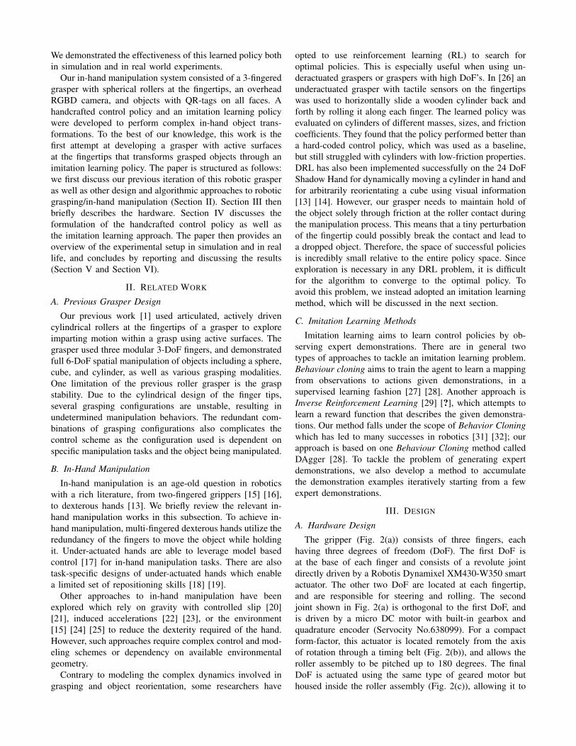
A. Hardware Design
The gripper (Fig. 2(a)) consists of three fingers, eachhaving three degrees of freedom (DoF). The first DoF isat the base of each finger and consists of a revolute jointdirectly driven by a Robotis Dynamixel XM430-W350 smartactuator. The other two DoF are located at each fingertip,and are responsible for steering and rolling. The secondjoint shown in Fig. 2(a) is orthogonal to the first DoF, andis driven by a micro DC motor with built-in gearbox andquadrature encoder (Servocity No.638099). For a compactform-factor, this actuator is located remotely from the axisof rotation through a timing belt (Fig. 2(b)), and allows theroller assembly to be pitched up to 180 degrees. The finalDoF is actuated using the same type of geared motor buthoused inside the roller assembly (Fig. 2(c)), allowing it to
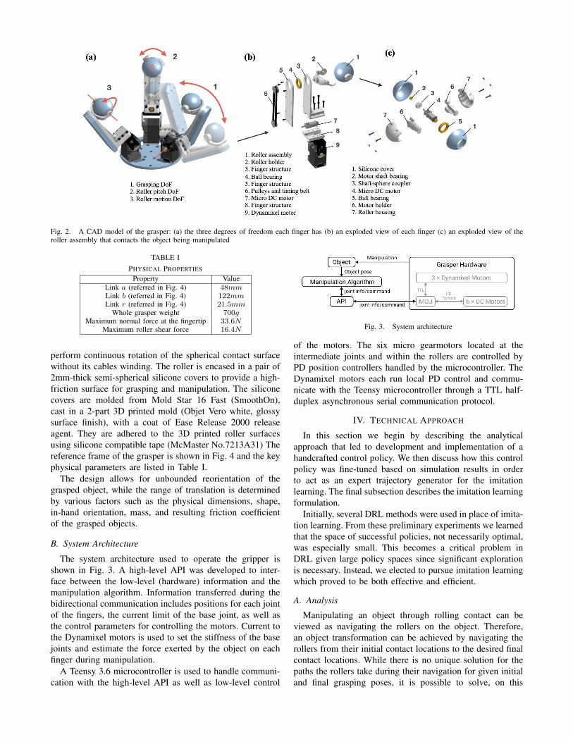
Fig. 2. A CAD model of the grasper: (a) the three degrees of freedom each finger has (b) an exploded view of each finger (c) an exploded view of theroller assembly that contacts the object being manipulated
TABLE IPHYSICAL PROPERTIES
Property ValueLink a (referred in Fig. 4) 48mmLink b (referred in Fig. 4) 122mmLink r (referred in Fig. 4) 21.5mm
Whole grasper weight 700gMaximum normal force at the fingertip 33.6N
Maximum roller shear force 16.4N
perform continuous rotation of the spherical contact surfacewithout its cables winding. The roller is encased in a pair of2mm-thick semi-spherical silicone covers to provide a high-friction surface for grasping and manipulation. The siliconecovers are molded from Mold Star 16 Fast (SmoothOn),cast in a 2-part 3D printed mold (Objet Vero white, glossysurface finish), with a coat of Ease Release 2000 releaseagent. They are adhered to the 3D printed roller surfacesusing silicone compatible tape (McMaster No.7213A31) Thereference frame of the grasper is shown in Fig. 4 and the keyphysical parameters are listed in Table I.
The design allows for unbounded reorientation of thegrasped object, while the range of translation is determinedby various factors such as the physical dimensions, shape,in-hand orientation, mass, and resulting friction coefficientof the grasped objects.
B. System Architecture
The system architecture used to operate the gripper isshown in Fig. 3. A high-level API was developed to inter-face between the low-level (hardware) information and themanipulation algorithm. Information transferred during thebidirectional communication includes positions for each jointof the fingers, the current limit of the base joint, as well asthe control parameters for controlling the motors. Current tothe Dynamixel motors is used to set the stiffness of the basejoints and estimate the force exerted by the object on eachfinger during manipulation.
A Teensy 3.6 microcontroller is used to handle communi-cation with the high-level API as well as low-level control
Fig. 3. System architecture
of the motors. The six micro gearmotors located at theintermediate joints and within the rollers are controlled byPD position controllers handled by the microcontroller. TheDynamixel motors each run local PD control and commu-nicate with the Teensy microcontroller through a TTL half-duplex asynchronous serial communication protocol.
IV. TECHNICAL APPROACH
In this section we begin by describing the analyticalapproach that led to development and implementation of ahandcrafted control policy. We then discuss how this controlpolicy was fine-tuned based on simulation results in orderto act as an expert trajectory generator for the imitationlearning. The final subsection describes the imitation learningformulation.
Initially, several DRL methods were used in place of imita-tion learning. From these preliminary experiments we learnedthat the space of successful policies, not necessarily optimal,was especially small. This becomes a critical problem inDRL given large policy spaces since significant explorationis necessary. Instead, we elected to pursue imitation learningwhich proved to be both effective and efficient.
A. Analysis
Manipulating an object through rolling contact can beviewed as navigating the rollers on the object. Therefore,an object transformation can be achieved by navigating therollers from their initial contact locations to the desired finalcontact locations. While there is no unique solution for thepaths the rollers take during their navigation for given initialand final grasping poses, it is possible to solve, on this
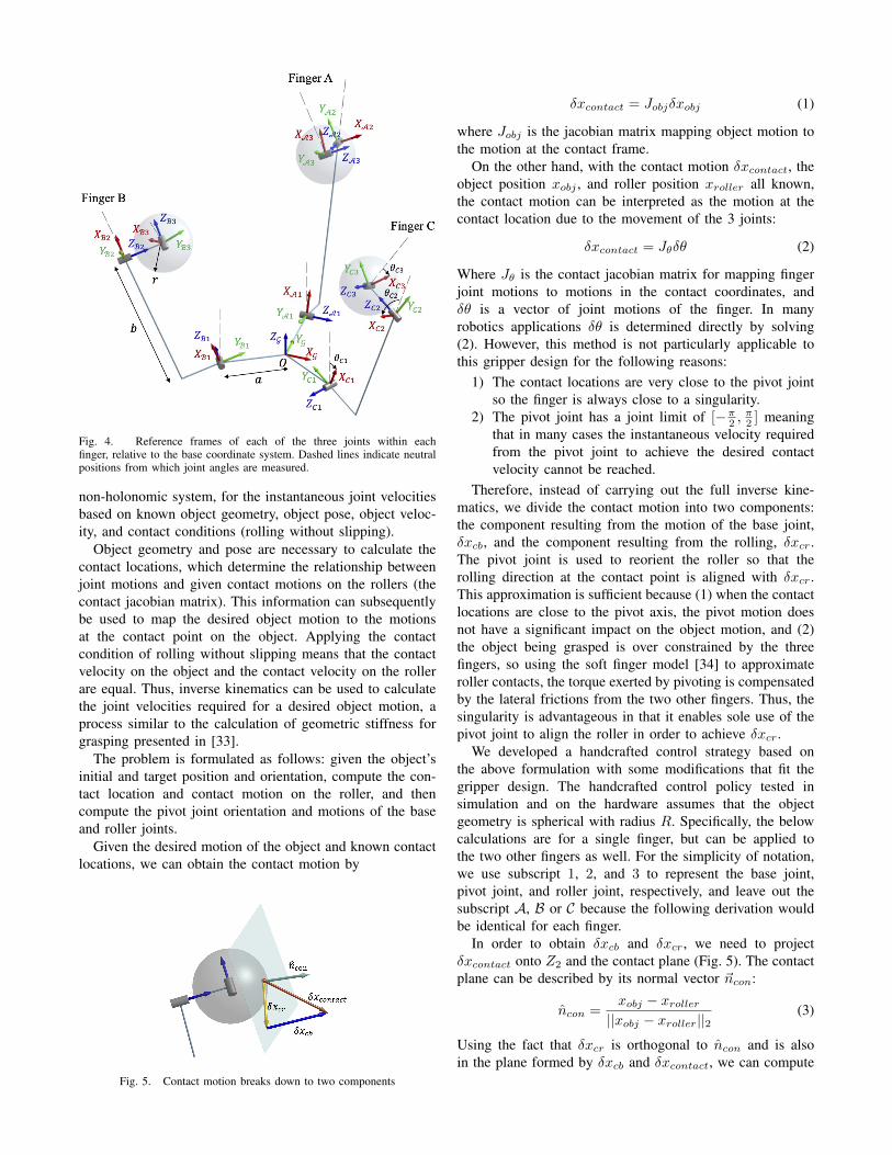
Fig. 4. Reference frames of each of the three joints within eachfinger, relative to the base coordinate system. Dashed lines indicate neutralpositions from which joint angles are measured.
non-holonomic system, for the instantaneous joint velocitiesbased on known object geometry, object pose, object veloc-ity, and contact conditions (rolling without slipping).
Object geometry and pose are necessary to calculate thecontact locations, which determine the relationship betweenjoint motions and given contact motions on the rollers (thecontact jacobian matrix). This information can subsequentlybe used to map the desired object motion to the motionsat the contact point on the object. Applying the contactcondition of rolling without slipping means that the contactvelocity on the object and the contact velocity on the rollerare equal. Thus, inverse kinematics can be used to calculatethe joint velocities required for a desired object motion, aprocess similar to the calculation of geometric stiffness forgrasping presented in [33].
The problem is formulated as follows: given the object’sinitial and target position and orientation, compute the con-tact location and contact motion on the roller, and thencompute the pivot joint orientation and motions of the baseand roller joints.
Given the desired motion of the object and known contactlocations, we can obtain the contact motion by
Fig. 5. Contact motion breaks down to two components
δxcontact = Jobjδxobj (1)
where Jobj is the jacobian matrix mapping object motion tothe motion at the contact frame.
On the other hand, with the contact motion δxcontact, theobject position xobj , and roller position xroller all known,the contact motion can be interpreted as the motion at thecontact location due to the movement of the 3 joints:
δxcontact = Jθδθ (2)
Where Jθ is the contact jacobian matrix for mapping fingerjoint motions to motions in the contact coordinates, andδθ is a vector of joint motions of the finger. In manyrobotics applications δθ is determined directly by solving(2). However, this method is not particularly applicable tothis gripper design for the following reasons:
1) The contact locations are very close to the pivot jointso the finger is always close to a singularity.
2) The pivot joint has a joint limit of [−π2 ,π2 ] meaning
that in many cases the instantaneous velocity requiredfrom the pivot joint to achieve the desired contactvelocity cannot be reached.
Therefore, instead of carrying out the full inverse kine-matics, we divide the contact motion into two components:the component resulting from the motion of the base joint,δxcb, and the component resulting from the rolling, δxcr.The pivot joint is used to reorient the roller so that therolling direction at the contact point is aligned with δxcr.This approximation is sufficient because (1) when the contactlocations are close to the pivot axis, the pivot motion doesnot have a significant impact on the object motion, and (2)the object being grasped is over constrained by the threefingers, so using the soft finger model [34] to approximateroller contacts, the torque exerted by pivoting is compensatedby the lateral frictions from the two other fingers. Thus, thesingularity is advantageous in that it enables sole use of thepivot joint to align the roller in order to achieve δxcr.
We developed a handcrafted control strategy based onthe above formulation with some modifications that fit thegripper design. The handcrafted control policy tested insimulation and on the hardware assumes that the objectgeometry is spherical with radius R. Specifically, the belowcalculations are for a single finger, but can be applied tothe two other fingers as well. For the simplicity of notation,we use subscript 1, 2, and 3 to represent the base joint,pivot joint, and roller joint, respectively, and leave out thesubscript A, B or C because the following derivation wouldbe identical for each finger.
In order to obtain δxcb and δxcr, we need to projectδxcontact onto Z2 and the contact plane (Fig. 5). The contactplane can be described by its normal vector ~ncon:
ncon =xobj − xroller||xobj − xroller||2
(3)
Using the fact that δxcr is orthogonal to ncon and is alsoin the plane formed by δxcb and δxcontact, we can compute
the direction of δxcr as:
δxcr =(δxcb × δxcontact)× ncon||(δxcb × δxcontact)× ncon||2
(4)
It is also easy to find that the direction of δxcb aligns withZ2:
δxcb = Z2 (5)
Projecting δxcontact onto δxcb and δxcr gives δxcb and δxcr.It is equivalent to solving α and β in equation:
δxcontact = αδxcb + βδxcr (6)
By cross multiplying δxcb and δxcr to (6), respectively, wecan solve for α and β, and the resulting δxcb and δxcrare shown below. Note that nz is only used to extract themagnitude from the cross products.
nz =δxcr × δxcb||δxcr × δxcb||2
(7)
δxcb =nz · (δxcr × δxcontact)nz · (δxcr × δxcb)
δxcb (8)
δxcr =nz(·δxcb × δxcontact)nz · (δxcb × δxcr)
δxcr (9)
The joint velocity of base joint (ω1) and roller joint (ω3) canbe calculated using inverse kinematics.
The final step is to calculate the pivot angle θ2 to alignthe rolling direction with δxcr:
Z3 = ± Z2 × δxcr||Z2 × δxcr||2
(10)
Note that because there is a joint limit at the pivot, weare limiting Z3 to always have a component along the Z0
direction. The pivot angle θ2 can be calculated by
θ2 = arccos
(Z1 · Z3
||Z1||2||Z3||2
)(11)
The above process only describes how each joint shouldmove given the instantaneous desired velocity of the object;no path planning is used for navigating the rollers giventhe initial and target poses of the object. In our case, wesimply compute the difference between the initial and targetpose, and set the desired velocity equal to a scaling factormultiplied by this computed difference: δxobj = λ∆xobj .This method works very well for convex objects whoseradii of curvature do not change drastically. Experimentalvalidation of manipulating a cube is shown in Section V.
B. Handcrafted Control Policy
The handcrafted control policy is formulated accordingto the results from the previous section. Given the currentobject position and orientation, the target object positionand orientation, and the current joint values, the positionsof all nine joints are calculated for the following time step.One difference between the implemented policy and thetheoretical policy is that the base joint velocities are not
controlled based on the derivation above. Instead, they areposition controlled to a setpoint in order for the rollers tomaintain contact with the object. This is because we arefocusing on the rotation of the object instead of translation.The main purpose of the base joint in our case is to keep therollers in contact with the object. The analytical approachpresented in the previous section performs both translationand rotation. The translation capability of the grasper isdemonstrated in the complementary video through scriptedmovements. However, the translation capability is relativelylimited compared to the rotation capability, which is why wedecided to focus on object rotation in the control policy.
C. Imitation Learning Algorithm
We adopted imitation learning, specifically BehaviorCloning in order to learn how to transform an object. Theoptimal policy was learned through expert demonstrationscharacterized by the above handcrafted control policy. Be-havior Cloning is particularly useful when it is difficult toexplicitly specify the reward function.
In our case, the state space is defined as |S| ∈ R35, andconsists of the following: the current state of the grasper(s1 → s9), current object position (s10 → s12), currentobject quaternion (s13 → s16), previous object position(s17 → s19), previous object quaternion (s20 → s23),object termination position (s24 → s26), object terminationorientation in angle-axis representation (s27 → s29), objectinitial position (s30 → s32), and object initial orientation inangle-axis representation (s33 → s35). The action space isdefined as |A| ∈ R9 and contains the nine joint positions(a1 → a9).
We constructed a deep neural network to determine theactions for each of the nine gripper joints. The networkconsisted of three fully connected hidden layers with leakyReLU activations, except at the output layer, and 256 nodesin each hidden layer.
The handcrafted control policy from the previous sectionwas used to generate N expert trajectories, which are simplya series of state-action pairs. The ith trajectory is defined as:
T (i) = [(s(i)0 , a
(i)0 ), (s
(i)1 , a
(i)1 ), . . . ] (12)
We first trained our policy π0(si) to predict the expertaction by minimizing the loss L between π0(sij) and aij ina supervised approach:
Lij = ‖π0(sij)− aij‖2, ∀ sj ∈ |T i|, i ∈ N (13)
Subsequent policy updates are computed according to DAg-ger [28].
We also implemented a method to increase the numberof expert demonstrations iteratively. For a given object,every object transformation trajectory is specified by a 12-dimensional vector containing the object starting and tar-get position and orientation: (xiobj,s, q
iobj,s, x
iobj,t, q
iobj,t). By
imitating the expert demonstration examples, we learn apolicy supported by these expert demonstrations. This controlembedding is able to interpolate between known trajectories
using a nearest neighbor policy in order to generate trajec-tories for previously unseen transformations.
Based on the learned policy, we accumulate nearby trans-formations. Let D = (xiobj,s, q
iobj,s, x
iobj,t, q
iobj,t) represent
the transformations which our policy already knows. If aninterpolated trajectory transformation is nearby to one of thetransformations in D, we add the transformation to D, andthen continue to train our policy based on the transformationdemonstrations in D. Through this fashion, we kept growingand maintaining a traversable graph of transforming theobject between various poses, similar to [35]. The learnedcontrol policy could also be treated as an efficient initializa-tion for a deep reinforcement learning approach or motionplanning for in-hand manipulations.
V. EXPERIMENTS
A. Simulation Experiments
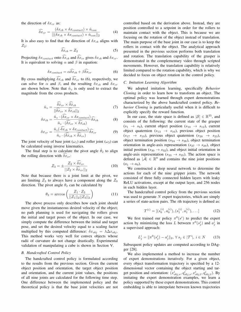
Mujoco 2.0 was used to simulate both the handcraftedcontrol policy and the learned policy before transferringthem to the physical setup (see Fig. 6). By default, Mujocoassumes a soft-contact model which leads to relatively slip-pery contacts, but the solver parameters (solref and solimp)were changed to have a harder contact model in order tobetter model the friction between the object and the sphericalrollers. An elliptical friction cone was used along with theNewton solver to evaluate these constraints.
The gripper was modeled in the software, and the fol-lowing setup was specified. The base joints were positioncontrolled, and had their force output clamped; these settingsallowed the fingers to act compliantly and conform to anobject’s shape as it was reoriented, and stabilized the grasp.The pivots had a rotation range from [−π2 ,
π2 ] (with the zero
position corresponding with the roller axis aligned along thelength of the finger) in order to represent the limited rangein the physical setup due to motor wires. A pivot rotationthreshold of 3◦ per time step was used to prohibit quickjumps between the two rotation limits in favor of smoothermotion that stabilized the simulation.
Sensors were placed at all nine joints to read joint posi-tions and two sensors were placed on the object to obtainits orientation (quaternion) and 3D position relative to theglobal frame. The learned policy outputted values for all ninejoints. The handcrafted control policy only used the latter two
Fig. 6. A visualization of our simulation in Mujoco. In simulation thegripper maintains the same physical design as the real gripper.
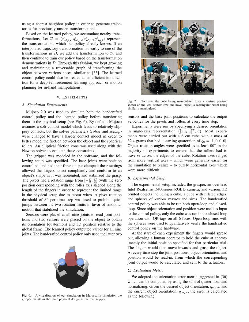
Fig. 7. Top row: the cube being manipulated from a starting positionshown on the left. Bottom row: the novel object, a rectangular prism beingsimilarly manipulated
sensors and the base joint positions to calculate the outputvelocities for the pivots and rollers at every time step.
Experiments were run by specifying a desired orientationin angle-axis representation
([x, y, z]T , θ
). Most experi-
ments were carried out with a 6 cm cube with a mass of32.4 grams that had a starting quaternion of q0 = [1, 0, 0, 0].Object rotation angles were specified as at least 90◦ in themajority of experiments to ensure that the rollers had totraverse across the edges of the cube. Rotation axes rangedfrom more vertical axes – which were generally easier forthe simulation to realize – to purely horizontal axes whichwere more difficult.
B. Experimental Setup
The experimental setup included the grasper, an overheadIntel Realsense D400series RGBD camera, and various 3Dprinted objects including a cube, a cube with filleted edges,and spheres of various masses and sizes. The handcraftedcontrol policy was able to be run both open-loop and closed-loop. Since object orientation and position were used as inputto the control policy, only the cube was run in the closed-loopoperation with QR-tags on all 6 faces. Open-loop runs withthe spheres were used to qualitatively verify the handcraftedcontrol policy on the hardware.
At the start of each experiment the fingers would spreadout, allowing a human operator to hold the cube at approx-imately the initial position specified for that particular trial.The fingers would then move inwards and grasp the object.At every time step the joint positions, object orientation, andposition would be read-in, from which the correspondingjoint output would be calculated and sent to the actuators.
C. Evaluation Metric
We adopted the orientation error metric suggested in [36]which can be computed by using the sum of quaternions andnormalizing. Given the desired object orientation, qobj,d, andthe current object orientation, qobj,c, the error is calculatedas the following:
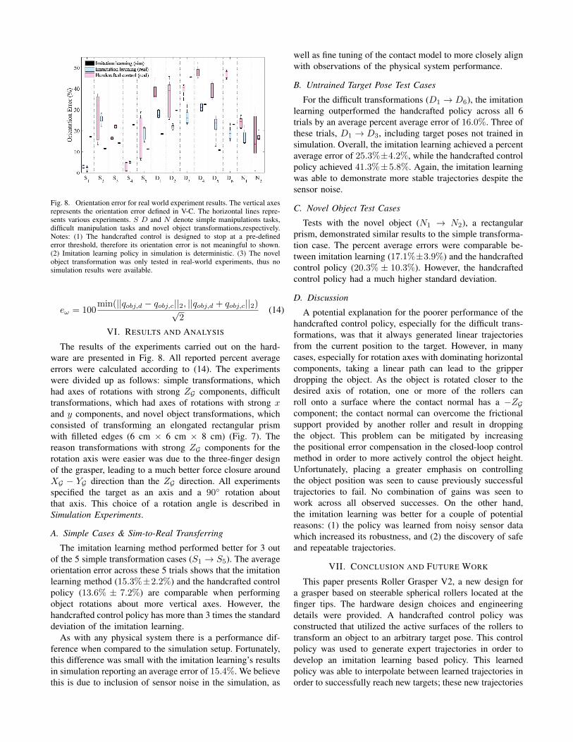
Fig. 8. Orientation error for real world experiment results. The vertical axesrepresents the orientation error defined in V-C. The horizontal lines repre-sents various experiments. S D and N denote simple manipulations tasks,difficult manipulation tasks and novel object transformations,respectively.Notes: (1) The handcrafted control is designed to stop at a pre-definederror threshold, therefore its orientation error is not meaningful to shown.(2) Imitation learning policy in simulation is deterministic. (3) The novelobject transformation was only tested in real-world experiments, thus nosimulation results were available.
eω = 100min(||qobj,d − qobj,c||2, ||qobj,d + qobj,c||2)√
2(14)
VI. RESULTS AND ANALYSIS
The results of the experiments carried out on the hard-ware are presented in Fig. 8. All reported percent averageerrors were calculated according to (14). The experimentswere divided up as follows: simple transformations, whichhad axes of rotations with strong ZG components, difficulttransformations, which had axes of rotations with strong xand y components, and novel object transformations, whichconsisted of transforming an elongated rectangular prismwith filleted edges (6 cm × 6 cm × 8 cm) (Fig. 7). Thereason transformations with strong ZG components for therotation axis were easier was due to the three-finger designof the grasper, leading to a much better force closure aroundXG − YG direction than the ZG direction. All experimentsspecified the target as an axis and a 90◦ rotation aboutthat axis. This choice of a rotation angle is described inSimulation Experiments.
A. Simple Cases & Sim-to-Real Transferring
The imitation learning method performed better for 3 outof the 5 simple transformation cases (S1 → S5). The averageorientation error across these 5 trials shows that the imitationlearning method (15.3%±2.2%) and the handcrafted controlpolicy (13.6% ± 7.2%) are comparable when performingobject rotations about more vertical axes. However, thehandcrafted control policy has more than 3 times the standarddeviation of the imitation learning.
As with any physical system there is a performance dif-ference when compared to the simulation setup. Fortunately,this difference was small with the imitation learning’s resultsin simulation reporting an average error of 15.4%. We believethis is due to inclusion of sensor noise in the simulation, as
well as fine tuning of the contact model to more closely alignwith observations of the physical system performance.
B. Untrained Target Pose Test Cases
For the difficult transformations (D1 → D6), the imitationlearning outperformed the handcrafted policy across all 6trials by an average percent average error of 16.0%. Three ofthese trials, D1 → D3, including target poses not trained insimulation. Overall, the imitation learning achieved a percentaverage error of 25.3%±4.2%, while the handcrafted controlpolicy achieved 41.3%±5.8%. Again, the imitation learningwas able to demonstrate more stable trajectories despite thesensor noise.
C. Novel Object Test Cases
Tests with the novel object (N1 → N2), a rectangularprism, demonstrated similar results to the simple transforma-tion case. The percent average errors were comparable be-tween imitation learning (17.1%±3.9%) and the handcraftedcontrol policy (20.3% ± 10.3%). However, the handcraftedcontrol policy had a much higher standard deviation.
D. Discussion
A potential explanation for the poorer performance of thehandcrafted control policy, especially for the difficult trans-formations, was that it always generated linear trajectoriesfrom the current position to the target. However, in manycases, especially for rotation axes with dominating horizontalcomponents, taking a linear path can lead to the gripperdropping the object. As the object is rotated closer to thedesired axis of rotation, one or more of the rollers canroll onto a surface where the contact normal has a −ZGcomponent; the contact normal can overcome the frictionalsupport provided by another roller and result in droppingthe object. This problem can be mitigated by increasingthe positional error compensation in the closed-loop controlmethod in order to more actively control the object height.Unfortunately, placing a greater emphasis on controllingthe object position was seen to cause previously successfultrajectories to fail. No combination of gains was seen towork across all observed successes. On the other hand,the imitation learning was better for a couple of potentialreasons: (1) the policy was learned from noisy sensor datawhich increased its robustness, and (2) the discovery of safeand repeatable trajectories.
VII. CONCLUSION AND FUTURE WORK
This paper presents Roller Grasper V2, a new design fora grasper based on steerable spherical rollers located at thefinger tips. The hardware design choices and engineeringdetails were provided. A handcrafted control policy wasconstructed that utilized the active surfaces of the rollers totransform an object to an arbitrary target pose. This controlpolicy was used to generate expert trajectories in order todevelop an imitation learning based policy. This learnedpolicy was able to interpolate between learned trajectories inorder to successfully reach new targets; these new trajectories
were placed in a buffer of known trajectories in order todevelop a traversable graph. Experiments for the handcraftedpolicy and the learned policy demonstrated the utility of thisgraph for generating safe trajectories, as the learned policyoutperformed the handcrafted policy for all difficult targetposes. For simple cases, the two policies performed compa-rably, except the learned policy had much lower variancein the trajectory. Future work includes reducing the sizeof the rollers to allow for manipulation of smaller objects,developing a novel mechanism that solves the non-holonomicconstraints and incorporating tactile sensing on the rollers toprovide high-fidelity feedback.
REFERENCES
[1] S. Yuan, A. D. Epps, J. B. Nowak, and J. K. Salisbury, “Design ofa roller-based dexterous hand for object grasping and within-handmanipulation,” in 2020 IEEE International Conference on Roboticsand Automation, May 2020.
[2] C. Piazza, G. Grioli, M. Catalano, and A. Bicchi, “A century of robotichands,” Annual Review of Control, Robotics, and Autonomous Systems,vol. 2, pp. 1–32, 2019.
[3] M. A. Diftler, J. S. Mehling, M. E. Abdallah, N. A. Radford, L. B.Bridgwater, A. M. Sanders, R. S. Askew, D. M. Linn, J. D. Yamokoski,F. A. Permenter, B. K. Hargrave, R. Platt, R. T. Savely, and R. O.Ambrose, “Robonaut 2 - the first humanoid robot in space,” in2011 IEEE International Conference on Robotics and Automation,pp. 2178–2183, May 2011.
[4] Shadow Robot Company, “Design of a dextrous hand for advancedCLAWAR applications,” in Proceedings of the 6th International con-ference on climbing and walking robots and the supporting technolo-gies for mobile machines, pp. 691–698, September 2003.
[5] M. Grebenstein, A. Albu-Schaffer, T. Bahls, M. Chalon, O. Eiberger,W. Friedl, R. Gruber, S. Haddadin, U. Hagn, R. Haslinger, H. Hoppner,S. Jorg, M. Nickl, A. Nothhelfer, F. Petit, J. Reill, N. Seitz,T. Wimbock, S. Wolf, T. Wusthoff, and G. Hirzinger, “The dlr handarm system,” in 2011 IEEE International Conference on Robotics andAutomation, pp. 3175–3182, May 2011.
[6] R. R. Ma and A. M. Dollar, “An underactuated hand for efficientfinger-gaiting-based dexterous manipulation,” in 2014 IEEE Inter-national Conference on Robotics and Biomimetics (ROBIO 2014),pp. 2214–2219, Dec 2014.
[7] A. M. Dollar and R. D. Howe, “The highly adaptive sdm hand: Designand performance evaluation,” The International Journal of RoboticsResearch, vol. 29, no. 5, pp. 585–597, 2010.
[8] H. Stuart, S. Wang, O. Khatib, and M. R. Cutkosky, “The oceanone hands: An adaptive design for robust marine manipulation,” TheInternational Journal of Robotics Research, vol. 36, no. 2, pp. 150–166, 2017.
[9] N. Rojas, R. R. Ma, and A. M. Dollar, “The gr2 gripper: an un-deractuated hand for open-loop in-hand planar manipulation,” IEEETransactions on Robotics, vol. 32, no. 3, pp. 763–770, 2016.
[10] N. Govindan and A. Thondiyath, “Design and Analysis of a Multi-modal Grasper Having Shape Conformity and Within-Hand Manipu-lation With Adjustable Contact Forces,” Journal of Mechanisms andRobotics, vol. 11, 07 2019. 051012.
[11] V. Tincani, M. G. Catalano, E. Farnioli, M. Garabini, G. Grioli,G. Fantoni, and A. Bicchi, “Velvet fingers: A dexterous gripperwith active surfaces,” in 2012 IEEE/RSJ International Conference onIntelligent Robots and Systems, pp. 1257–1263, Oct 2012.
[12] R. R. Ma and A. M. Dollar, “In-hand manipulation primitives fora minimal, underactuated gripper with active surfaces,” in proceed-ings of the ASME 2016 International Design Engineering TechnicalConferences (IDETC), Computers and Information in EngineeringConference (CIE), p. V05AT07A072, 2016.
[13] V. Kumar, E. Todorov, and S. Levine, “Optimal control with learned lo-cal models: Application to dexterous manipulation,” in 2016 IEEE In-ternational Conference on Robotics and Automation (ICRA), pp. 378–383, IEEE, 2016.
[14] O. M. Andrychowicz, B. Baker, M. Chociej, R. Jozefowicz, B. Mc-Grew, J. Pachocki, A. Petron, M. Plappert, G. Powell, A. Ray, et al.,“Learning dexterous in-hand manipulation,” The International Journalof Robotics Research, vol. 39, no. 1, pp. 3–20, 2020.
[15] N. Chavan-Dafle, R. Holladay, and A. Rodriguez, “In-hand manipula-tion via motion cones,” arXiv preprint arXiv:1810.00219, 2018.
[16] S. Cruciani, C. Smith, D. Kragic, and K. Hang, “Dexterous manipula-tion graphs,” in 2018 IEEE/RSJ International Conference on IntelligentRobots and Systems (IROS), pp. 2040–2047, IEEE, 2018.
[17] M. Liarokapis and A. M. Dollar, “Deriving dexterous, in-hand ma-nipulation primitives for adaptive robot hands,” in 2017 IEEE/RSJInternational Conference on Intelligent Robots and Systems (IROS),pp. 1951–1958, IEEE, 2017.
[18] N. Rahman, L. Carbonari, M. D’Imperio, C. Canali, D. G. Caldwell,and F. Cannella, “A dexterous gripper for in-hand manipulation,” in2016 IEEE International Conference on Advanced Intelligent Mecha-tronics (AIM), pp. 377–382, July 2016.
[19] W. G. Bircher, A. M. Dollar, and N. Rojas, “A two-fingered robot grip-per with large object reorientation range,” in 2017 IEEE InternationalConference on Robotics and Automation (ICRA), pp. 3453–3460, May2017.
[20] Y. Karayiannidis, K. Pauwels, C. Smith, D. Kragic, et al., “In-handmanipulation using gravity and controlled slip,” in 2015 IEEE/RSJInternational Conference on Intelligent Robots and Systems (IROS),pp. 5636–5641, IEEE, 2015.
[21] D. L. Brock, “Enhancing the dexterity of a robot hand using controlledslip,” in Proceedings. 1988 IEEE International Conference on Roboticsand Automation, pp. 249–251, IEEE, 1988.
[22] N. C. Dafle, A. Rodriguez, R. Paolini, B. Tang, S. S. Srinivasa,M. Erdmann, M. T. Mason, I. Lundberg, H. Staab, and T. Fuhlbrigge,“Extrinsic dexterity: In-hand manipulation with external forces,” in2014 IEEE International Conference on Robotics and Automation(ICRA), pp. 1578–1585, IEEE, 2014.
[23] J. Shi, J. Z. Woodruff, P. B. Umbanhowar, and K. M. Lynch, “Dynamicin-hand sliding manipulation,” IEEE Transactions on Robotics, vol. 33,no. 4, pp. 778–795, 2017.
[24] N. Chavan-Dafle and A. Rodriguez, “Prehensile pushing: In-handmanipulation with push-primitives,” in 2015 IEEE/RSJ InternationalConference on Intelligent Robots and Systems (IROS), pp. 6215–6222,IEEE, 2015.
[25] C. Eppner, R. Deimel, J. Alvarez-Ruiz, M. Maertens, and O. Brock,“Exploitation of environmental constraints in human and roboticgrasping,” The International Journal of Robotics Research, vol. 34,no. 7, pp. 1021–1038, 2015.
[26] H. Van Hoof, T. Hermans, G. Neumann, and J. Peters, “Learning robotin-hand manipulation with tactile features,” in 2015 IEEE-RAS 15thInternational Conference on Humanoid Robots (Humanoids), pp. 121–127, IEEE, 2015.
[27] D. A. Pomerleau, “Alvinn: An autonomous land vehicle in a neuralnetwork,” in Advances in neural information processing systems,pp. 305–313, 1989.
[28] S. Ross, G. Gordon, and D. Bagnell, “A reduction of imitation learningand structured prediction to no-regret online learning,” in Proceedingsof the fourteenth international conference on artificial intelligence andstatistics, pp. 627–635, 2011.
[29] A. Y. Ng, S. J. Russell, et al., “Algorithms for inverse reinforcementlearning.,”
[30] L. Shao, T. Migimatsu, Q. Zhang, K. Yang, and J. Bohg, “Con-cept2robot: Learning manipulation concepts from instructions andhuman demonstrations,” in Proceedings of Robotics: Science andSystems (RSS), July 2020.
[31] A. Billard, Y. Epars, S. Calinon, S. Schaal, and G. Cheng, “Discov-ering optimal imitation strategies,” Robotics and autonomous systems,vol. 47, no. 2-3, pp. 69–77, 2004.
[32] P. Pastor, H. Hoffmann, T. Asfour, and S. Schaal, “Learning andgeneralization of motor skills by learning from demonstration,” in 2009IEEE International Conference on Robotics and Automation, pp. 763–768, IEEE, 2009.
[33] M. R. Cutkosky and I. Kao, “Computing and controlling complianceof a robotic hand,” IEEE transactions on robotics and automation,vol. 5, no. 2, pp. 151–165, 1989.
[34] M. T. Mason and J. K. Salisbury Jr, “Robot hands and the mechanicsof manipulation,” 1985.
[35] S. Cruciani, K. Hang, C. Smith, and D. Kragic, “Dual-arm in-handmanipulation and regrasping using dexterous manipulation graphs,”arXiv preprint arXiv:1904.11382, 2019.
[36] D. Q. Huynh, “Metrics for 3d rotations: Comparison and analysis,”Journal of Mathematical Imaging and Vision, vol. 35, no. 2, pp. 155–164, 2009.