Embed Size (px)
Citation preview
ITEM NO. DESCRIPTION
SHEET NUMBER
OF
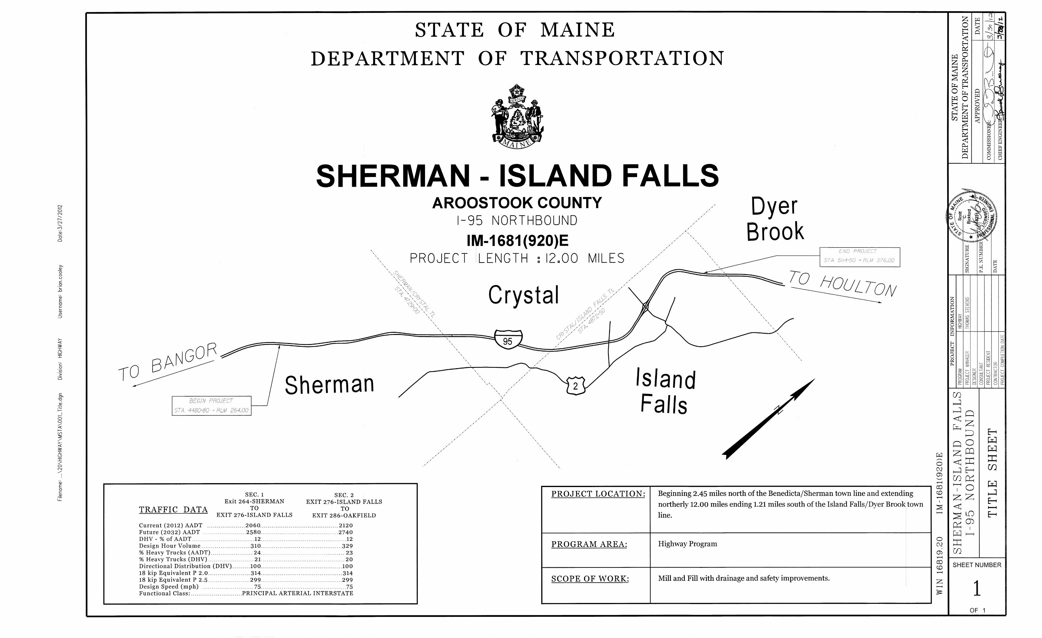
ESTIMATED BRIDGE QUANTITIES
QUANTITY QUANTITY QUANTITY
13
2
Patten Road
& Railroad
Br. No. 1403
Bog Brook
Road &
Fish Stream
Br. No. 1402
West Branch
Mattawamkeag
Br. No. 1401
UNITTOTAL
* Undetermined Location
Notes:
1. Estimated Quantities for each bridge are provided here for reference purposes only.
0
0
0
0
0
0.17
0
0
2
0.33
0
0.33
55
0
0
0
0
0
0
2
0
0
0
0
0.28
4
1
10
20
1280
8
8
1
0
0
0
0
0
0.66
6
40
1
0.34
0
0.34
104
0
0
0
0
0
0
1
1
0
1
1
0.47
4
1
10
20
800
8
8
1
1
66
56
17
255
0.17
0
0
4
0.33
1
0.33
142
490
110
1
10
1
1
0
0
1
0
0
0.25
4
1
10
20
1240
8
8
1
1
66
56
17
255
1
6
40
7
1
1
1
301
490
110
1
10
1
1
3
1
1
1
1
1
12
3
30
60
3320
24
24
3
LS
T
T
GAL
SF
LS
EA
LF
EA
LS
LS
LS
LF
SF
SF
CY
SF
CY
EA
EA
EA
EA
EA
LS
LS
EA
UN
CY
SY
SF
HR
HR
EA
REMOVING EXISTING CONCRETE WEARING SURFACE (680 SY)
HOT MIX ASPHALT 12.5 MM SURFACE
HOT MIX ASPHALT 12.5 MM BASE
BITUMINOUS TACK COAT - APPLIED
GRID/FABRIC COMPOSITE PAVEMENT INTERLAYER
FURNISH ALUMINUM BRIDGE RAIL COMPONENTS
ALUMINUM BRIDGE RAIL, 2 BAR POST REPLACEMENT
ALUMINUM BRIDGE RAIL, RAIL SECTION REPLACEMENT
ALUMINUM BRIDGE RAIL SPLICE RETROFIT
ALUMINUM BRIDGE RAIL SPLICE INSPECTION
HIGH PERFORMANCE WATERPROOFING MEMBRANE (680 SY)
PROTECTIVE COATING FOR CONCRETE SURFACES (112 SY)
REPAIRING GRANITE CURB JOINT AND BEDDING MORTAR
REPAIR OF UPWARD FACING SURFACES - TO REINFORCING STEEL <7.9 IN.
REPAIR OF UPWARD FACING SURFACES - BELOW REINFORCING STEEL <7.9 IN.
REPAIR OF UPWARD FACING SURFACES >7.9 IN.
REPAIR OF VERTICAL SURFACES < 7.9 IN.
REPAIR OF VERTICAL SURFACES > 7.9 IN
BRIDGE JOINT MODIFICATION TYPE 2
BRIDGE JOINT MODIFICATION TYPE 2A
BRIDGE JOINT MODIFICATION TYPE 2B
BRIDGE JOINT MODIFICATION TYPE 6
FABRIC TROUGH FOR FINGER JOINT
FABRIC COVERING FOR CONCRETE SURFACES
TEMPORARY CONCRETE BARRIER - TYPE 1 (880 LF)
PERMANENT CONCRETE TRANSITION BARRIER
WORK ZONE CRASH CUSHIONS
PLAIN RIPRAP
EROSION CONTROL GEOTEXTILE
REMOVING EXISTING PAVEMENT MARKING
AIR COMPRESSOR (INCLUDING OPERATOR)
AIR TOOL (INCLUDING OPERATOR)
FLASHING ARROW BOARD
202.30
403.208
403.213
409.15
429.34
507.0926
507.0927
507.0928
507.30
507.31
508.14
515.21
518.391
518.50
518.51
518.52
518.60
518.61
520.242
520.2421
520.2422
520.246
521.32
521.51
526.301
526.34
527.34
610.08
620.58
627.77
631.10
631.11
652.30
*
*
*
*
*
*
*
*
*
*
SHEET NUMBER
3OF 13
GENERAL
UTILITIES
STRUCTURAL
BRIDGE RAILING
CONSTRUCTION PHASING
1. Utilities in this contract are listed in Special Provision Section 104, Utilities.
2. All utility facilities shall be adjusted by the respective utilities unless otherwise noted. No utility
adjustment is anticipated.
3. The locations of the existing utilities, bridge wiring and monitoring instruments (i.e. Utilities and
Special Equipment) shown on these plans are based on the best available information and are
approximate. The Contractor shall verify the location of all existing utilities and special equipment
prior to starting work. The Contractor shall protect existing utilities and special equipment during
construction and shall provide temporary supports where required by his operations. Temporary
supports shall be approved by the utility or special equipment owner prior to their installation and
use. The cost of this work shall be considered incidental to the work required under Item 659.10
Mobilization.
1. All traffic control shall be in accordance with the Manual for Uniform Traffic Control Devices for
Streets and Highways, USDOT, FHWA, Latest Edition
2. Contractor shall submit traffic control plans for all bridges in accordance with the Special Provisions
105 & 652 and the Manual of Uniform Traffic Control Devices, latest edition.
3. Contractor shall provide one 12 foot travel lane minimum and two 1 foot shoulders in all work zones,
unless otherwise noted on the plans or in the specifications.
4. All lanes in long term lane closures and work zones shall be delineated with temporary paint lines
or temporary raised pavement markings. Temporary paint lines will not be permitted on the surface
course of new pavement. Temporary raised pavement markings shall only be used when approved by
the Resident.
5. Excessively wide lane widths may cause driver confusion. Contractor shall avoid lane widths in
excess of 15’-0" unless approved by the Resident.
6. Contractor shall install longitudinal pavement joints at crown lines or lane lines.
7. Placement of the high performance membrane shall be in accordance with standard specifications
and manufacturers published recommendations. Contractor shall submit proposed membrane overlap
details at the longitudinal joints to the Resident for review and approval. Details shall include proposed
methodology for bond breaker for the overlaps between construction phases as well as procedures for
infilling and removal of bituminous material without damage to the membrane.
8. Contractor is responsible for all maintenance of traffic required for all work including ramp traffic
control.
9. Long term lane closures required for bridge work shall be protected with temporary concrete
barrier at the work zones.
10. Long term lane closures shall be defined as closures that occur at a location for more than 3 days.
1. Project information referred to below may be accessed at the following MaineDOT web address:
http://maine.gov/mdot/comprehensive-list-projects/project-information.php.
2. The existing bridge plans may be accessed at the MaineDOT web address. The plans are
reproduction of the original drawings as prepared for the construction of the bridge. It is very
unlikely that the plans will show any construction field changes or any alterations which may have
been made to the bridge during its life span.
3. All dimensions, angles and stationing shown on existing plans are taken from as-built construction
drawings from 1965 through 1990, supplemented by limited field measurements and are not
guaranteed to be correct. All existing bridge information shall be verified in the field by the
Contractor prior to commencing any work.
4. The Resident shall review the embankment armor/slope protection at all drain replacement locations
and verify the existing embankment armor/slope protection is adequate to protect the
embankment/slope from eroding or undermining during heavy rain events. The Contractor shall
undertake embankment armor/slope protection modifications at the request/direction of the Resident.
The work, if required, will be paid for under the various hand labor and hourly equipment items.
1. All aluminum bridge rail, rail posts, and associated hardware components which are to be removed
shall be carefully salvaged by the Contractor and will remain property of the Department. Contractor
shall transport materials to the Maine DOT maintenance lot at 159 Bangor Street, Houlton, Maine.
Contact is Joel Rideout at 532-3684. Payment will be considered incidental to related Contract items.
2. The drawings show or note the approximate number of damaged bridge rail posts and damaged
bridge rail sections that are to be replaced on this project. The actual quantity of bridge rail and
post replacement shall be as directed by the Resident.
3. The Contractor shall furnish the quantity of bridge rail, posts, toggle bolts, splice bars and end
caps specified in the Contract. The Department will not furnish any bridge materials for this project.
See Special Provisions for additional information.
4. Misaligned bridge rail splices shall be modified in accordance with the project specifications,
standard and supplemental details and as noted on the drawings. All splice rail modification bolts
shall be furnished by the Contractor.
5. At the Resident’s discretion, and based on available materials, damaged bridge rail sections may be
replaced in either full length sections or in shorter rail sections. Bridge rail section replacement shall
be completed such that all proposed and existing lengths of rail are attached to a minimum of two
posts, and such that all rail splices are located two feet from a post.
6. Bridge rail posts that are relocated as part of the concrete transition barrier modifications, and
bridge rail sections shortened or extended as part of the concrete transition barrier modifications,
shall be considered incidental to the permanent concrete transition barrier pay item. All components
necessary to extend rails section or relocate bridge posts including rail, posts, toggle bolts, splice
bars, rail post anchor bolts, anchor bolt anchoring materials, and splice rail modification bolts shall be
furnished by the Contractor.
7. The quantities for bridge rail end caps assume full placement on many bridges. If the contractor
determines that rail end caps are present, replacement of those items may not be necessary, coordinate
with Resident. Materials purchased under this contract and not used shall become the property of the
Department.
8. The splice requirements for 2-Bar Aluminum Bridge Rail Type Z are documented in the Special
Provision 507.
1. Payment for removing existing concrete end posts will be considered incidental to item 526.34.
2. Reinforcing steel schedules will be the responsibility of the Contractor. Refer to Subsection 503.03
of the Standard Specifications for more information. Payment for all work associated with developing
reinforcing steel schedules will be considered incidental to related Contract items.
3. Protective coating for concrete surfaces shall be applied to the following areas of new concrete:
All exposed surfaces of concrete curbs,
Fascias down to the drip notch,
All exposed surfaces of Concrete Transition Barriers,
12 Inches below the top of backwalls on the back side.
Concrete wearing surfaces.
4. An NCHRP350 compliant impact attenuation system (work zone crash cushion) shall be installed
concurrently with the placement of each run of concrete barrier.
5. Removal of existing bridge rail transition barriers and installation of new bridge rail transition
barriers shall occur behind concrete barrier and NCHRP350 compliant impact attenuation systems
(work zone crash cushions).
6. Any damage to existing concrete or reinforcing steel resulting from the work performed, shall be
repaired or replaced by a method approved by the Resident at no cost to the Department.
7. All reinforcing steel that is to be exposed and reused shall be cleaned by a method approved by
the Resident. Payment shall be incidental to related contract items.
8. The integrity of existing approach pavement and subbase gravel shall be maintained during removal
of backwall concrete. Payment for any repair or damages shall be incidental to related contract items.
9. Gland seal(s) or compression seal(s) shall be approved by the Resident prior to installation of joint
armor.
10. All expansion joints shall be fabricated so the expansion joints construction joints align with the
bridge phasing. New seals shall be installed full length after all sections of the joint armor have
been installed.
11. All existing materials which are removed from the work area shall be removed from the site and
properly disposed of by the Contractor in a manner approved by the Resident. These existing
materials include, but are not limited to, concrete, metal casing, reinforcing steel, silt and other debris
on or attached to the structure within the work areas. The cost of removal and disposal shall be
incidental to the cost of the work items for which these removals are required.
12. Contractor shall form a one inch V-groove on the fascias at the horizontal joint between the curb
and slab.
13. Reinforcing steel shall have a 2 inch minimum cover unless otherwise noted.
14. Mortar for bedding and for joints in the granite curb shall contain an approved non-shrink
additive.
15. The Contractor is advised none of the bridge decks are scheduled to be scarified. Only the
existing pavement, membrane, and pavement shim (if applicable) are to be removed. See Section
202.031 of the Specifications for additional information.
16. If the depth of the deteriorated concrete is below the reinforcing steel then remove the concrete
to a minimum depth of 1 inch below the bars.
17. Where bridge rail posts are required to be relocated new hot dip galvanized anchor rods
conforming to ASTM F1554 Grade 50 shall be furnished and drilled and anchored into the existing
curb. The depth of embedment shall be sufficient to develop an ultimate tension capacity of 33 kips
per anchor rod. This work may also require replacement or repair of rail clamp bars, and replacement
of bolts, where the bolt or clamp bar threads are damaged during the rail disassembly process. Where
the Contractor elects to repair the damaged mounting bars the existing threads shall be repaired
through the use of a stainless steel heli-coil insert. The proposed repair shall be completed in a
manner which maintains the original fastener size and diameter. Payment for bridge rail post
relocation and associated materials, equipment, labor and incidentals necessary to complete the work
will be considered incidental to Item 526.34, Permanent Concrete Transition Barrier.
18. All transverse reinforcing steel in the deck and backwall shall run continuously along the full width
of the bridge. Payment for lap splices and threaded couplers will not be paid for directly, but shall be
considered incidental to the related contract items.
19. The reinforcing steel and anchor rod anchoring material shall be selected from Maine DOT’s
qualified products list. The contractor shall submit the proposed system to the resident for approval.
The selected anchoring material shall be installed in strict accordance with the manufacturer’s
recommendations. Reinforcing steel and anchor rods, drilled and anchored into existing concrete,
shall be embedded to develop 125% of the yield strength of the bar.
20. When a new joint is being installed or an existing joint is being substantially modified, and
field conditions permit, the approach side of the joint shall be set 1/8 " - 1/4 " higher than the departure
side of the joint. Under no circumstances shall the departing side of the joint be higher than the
approach side of the joint.
21. Deck or backwall repairs located below areas of elastomeric concrete shall be filled with Class
LP concrete and allowed to cure prior to placing elastomeric concrete. The concrete repairs shall be
completed to provide an elastomeric concrete thickness of 3". The depth of elastomeric concrete may
be increased to 4" maximum only in cases where doing so eliminates the need for patching with
Class LP concrete.
22. The contractor is required to have on-site a copy of the Technical Guideline No. 03732 or latest
version published by the International Concrete Repair Institute as well as a set of nine molded
replicas of surfaces textures, for use on this project. All associated costs considered incidental to
pay item 508.14.
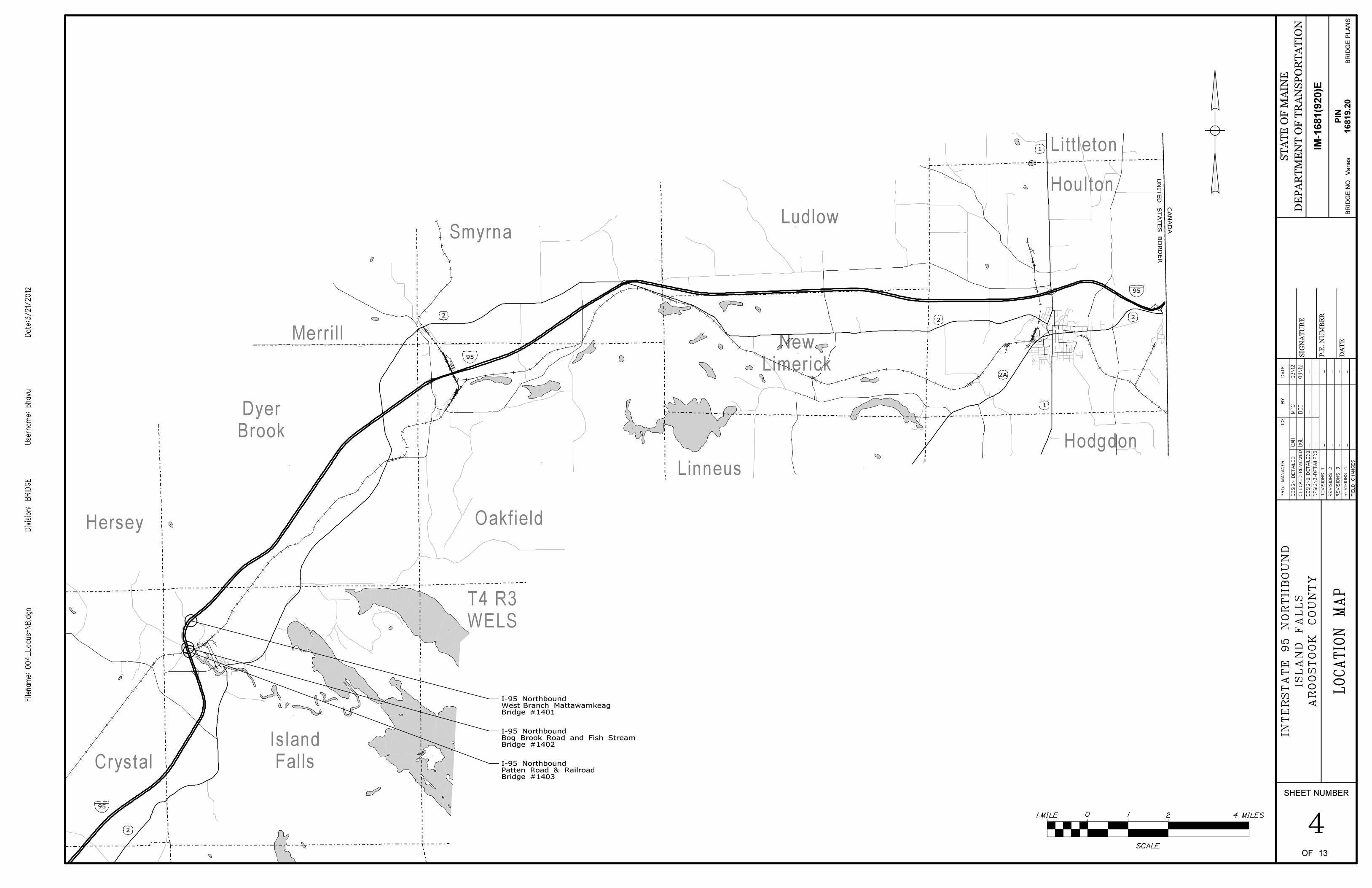
13
I-95 NorthboundWest Branch MattawamkeagBridge #1401
I-95 NorthboundPatten Road & RailroadBridge #1403
I-95 NorthboundBog Brook Road and Fish StreamBridge #1402
Hammond
Merrill
Ludlow
OakfieldHersey
Linneus
Crystal
Amity
Smyrna
Houlton
Hodgdon
Cary Plt.
Littleton
T4 R3
WELS
Island
Falls
Dyer
Brook
TA R2
WELS
New
Limerick
Moro
Plt.
T3 R4 T3 R3
Webbertown Twp. Dudley Twp.
SHEET NUMBER
5OF 13
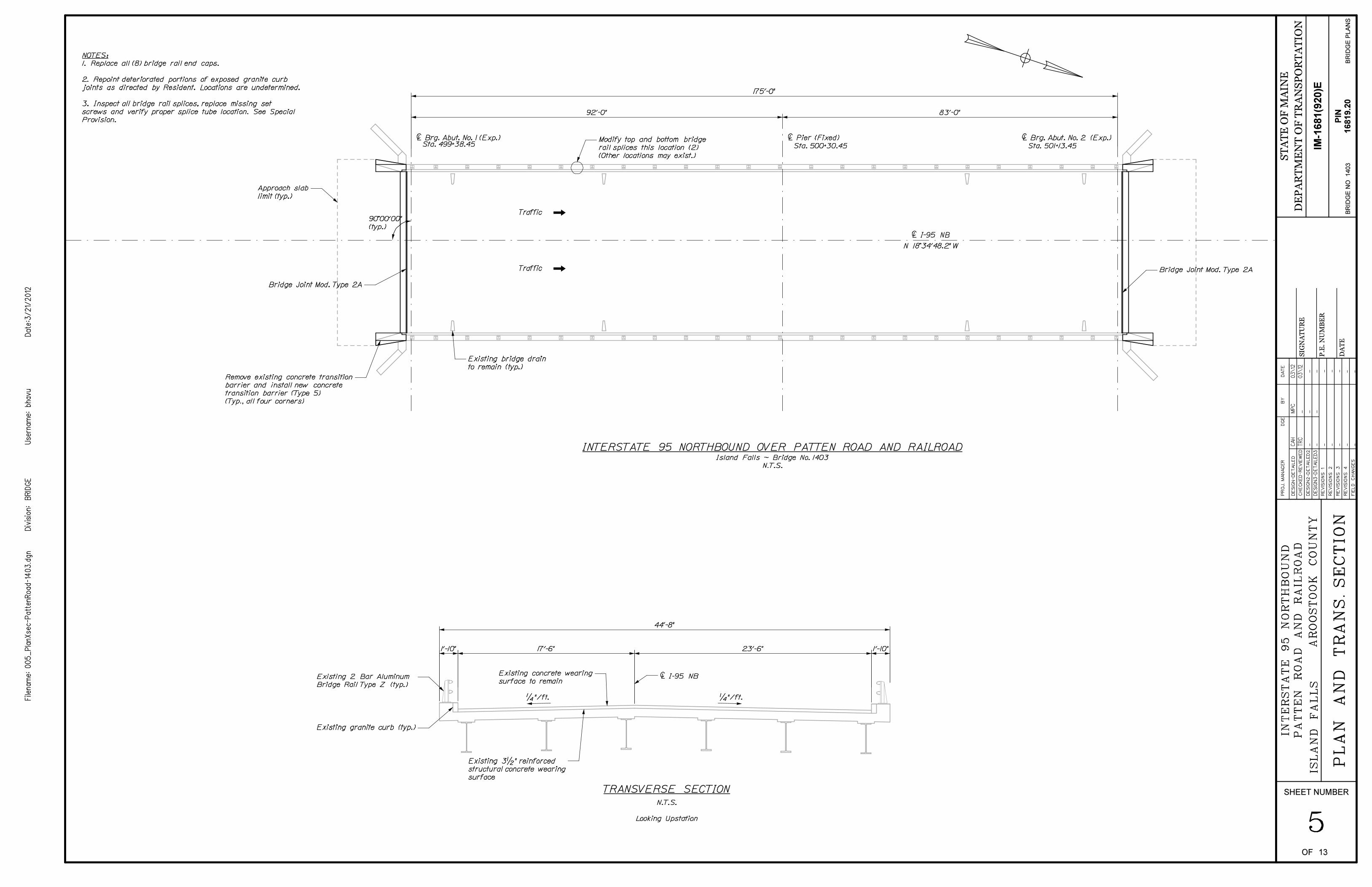
É I-95 NB
90^00’00"
(typ.)
Island Falls ~ Bridge No. 1403
N.T.S.
N 18^34’48.2" W
INTERSTATE 95 NORTHBOUND OVER PATTEN ROAD AND RAILROAD
Traffic
Traffic
É Pier (Fixed)
Sta. 500+30.45
É Brg. Abut. No. 2 (Exp.)
Sta. 501+13.45
É Brg. Abut. No. 1 (Exp.) Sta. 499+38.45
NOTES:
1. Replace all (8) bridge rail end caps.
2. Repoint deteriorated portions of exposed granite curb
joints as directed by Resident. Locations are undetermined.
3. Inspect all bridge rail splices, replace missing set
screws and verify proper splice tube location. See Special
Provision.
TRANSVERSE SECTION
1/4 "/ft. 1/4 "/ft.
N.T.S.
Looking Upstation
175’-0"
Bridge Joint Mod. Type 2A
Bridge Joint Mod. Type 2A
92’-0" 83’-0"
Approach slab
limit (typ.)
Remove existing concrete transition
barrier and install new concrete
transition barrier (Type 5)
(Typ., all four corners)
Existing bridge drain
to remain (typ.)
Modify top and bottom bridge
rail splices this location (2)
(Other locations may exist.)
1’-10" 17’-6" 23’-6"
É I-95 NBExisting 2 Bar Aluminum
Bridge Rail Type Z (typ.)
44’-8"
Existing granite curb (typ.)
Existing concrete wearing
surface to remain
Existing 3 1/2 " reinforced
structural concrete wearing
surface
1’-10"
SHEET NUMBER
6OF 13
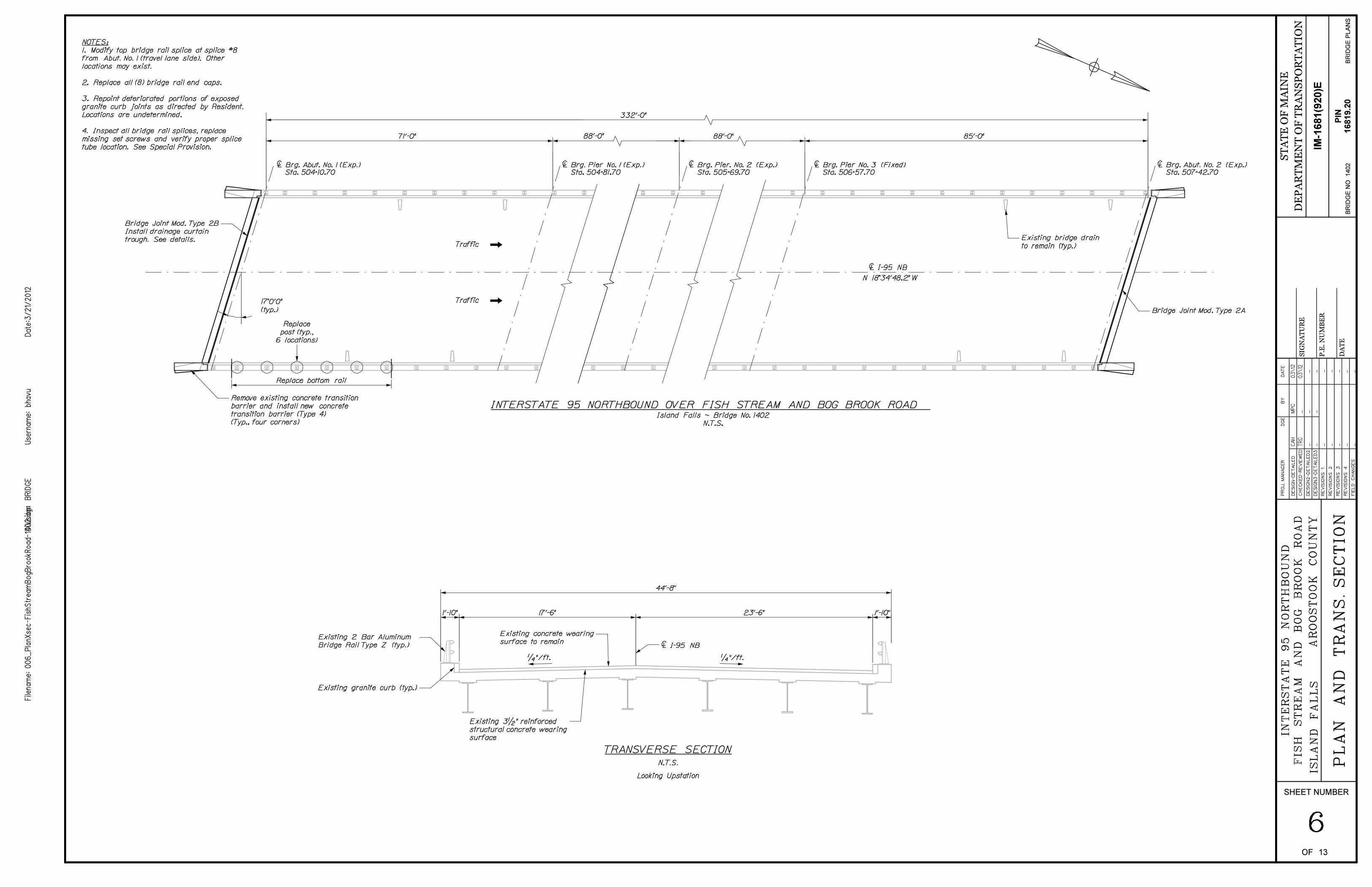
É I-95 NB
Island Falls ~ Bridge No. 1402
N.T.S.
Sta. 504+10.70 Sta. 507+42.70Sta. 504+81.70 Sta. 505+69.70 Sta. 506+57.70
88’-0" 88’-0"
INTERSTATE 95 NORTHBOUND OVER FISH STREAM AND BOG BROOK ROAD
Traffic
Traffic
N 18^34’48.2" W
É Brg. Abut. No. 1 (Exp.) É Brg. Pier No. 1 (Exp.) É Brg. Pier. No. 2 (Exp.) É Brg. Pier No. 3 (Fixed) É Brg. Abut. No. 2 (Exp.)
332’-0"
NOTES:
1. Modify top bridge rail splice at splice #8
from Abut. No. 1 (travel lane side). Other
locations may exist.
2. Replace all (8) bridge rail end caps.
3. Repoint deteriorated portions of exposed
granite curb joints as directed by Resident.
Locations are undetermined.
4. Inspect all bridge rail splices, replace
missing set screws and verify proper splice
tube location. See Special Provision.
TRANSVERSE SECTION
N.T.S.
Looking Upstation
1/4 "/ft. 1/4 "/ft.
17%%d0’0"
(typ.)
71’-0" 85’-0"
Bridge Joint Mod. Type 2A
Replace bottom rail
Remove existing concrete transition
barrier and install new concrete
transition barrier (Type 4)
(Typ., four corners)
Existing bridge drain
to remain (typ.)
Bridge Joint Mod. Type 2B
Install drainage curtain
trough. See details.
1’-10" 1’-10"17’-6" 23’-6"
É I-95 NB
Existing 3 1/2 " reinforced
structural concrete wearing
surface
Existing concrete wearing
surface to remain
Existing granite curb (typ.)
Existing 2 Bar Aluminum
Bridge Rail Type Z (typ.)
44’-8"
SHEET NUMBER
7OF 13
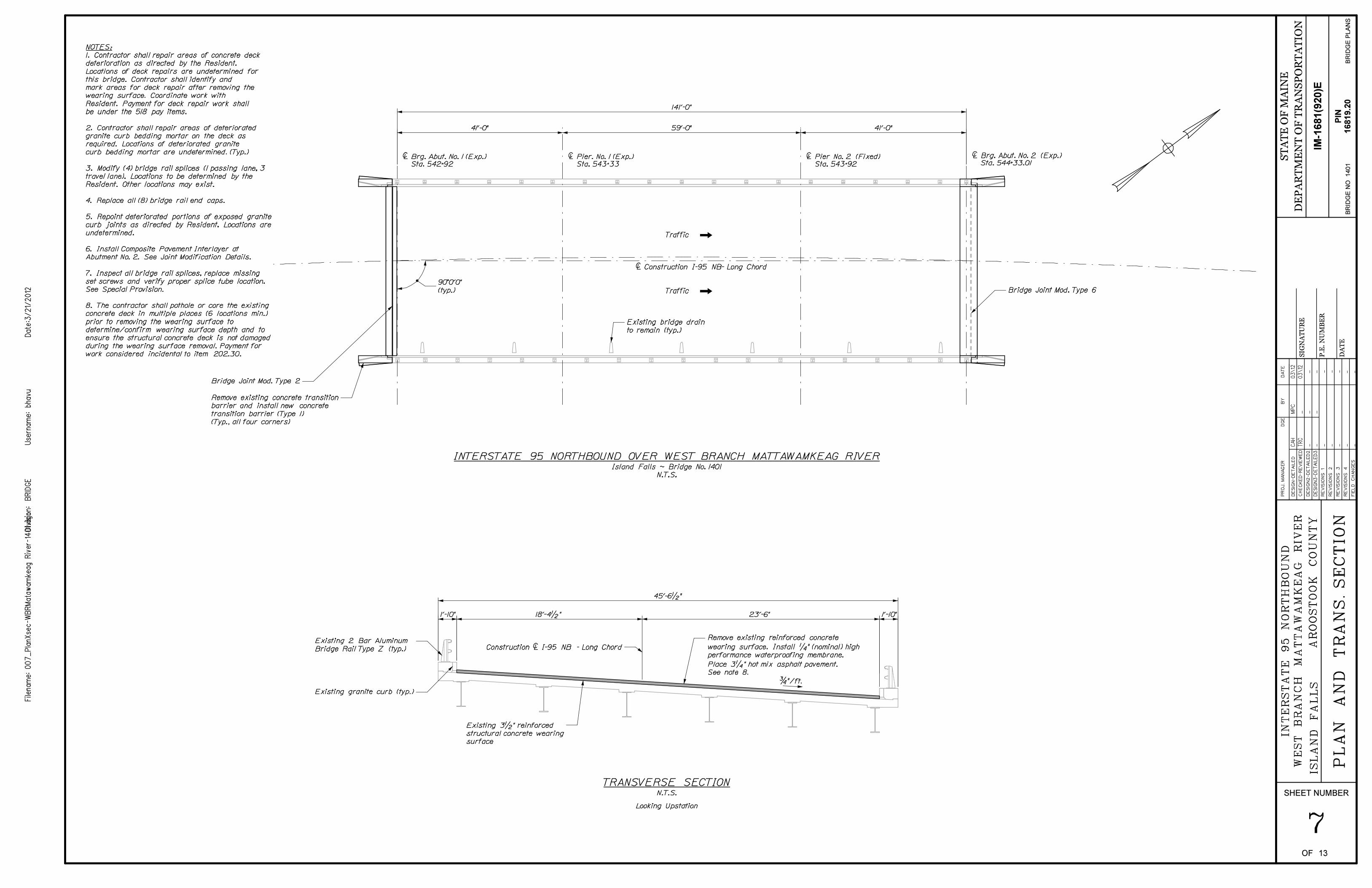
Sta. 542+92 Sta. 544+33.01
É Construction I-95 NB- Long Chord
Island Falls ~ Bridge No. 1401
N.T.S.
INTERSTATE 95 NORTHBOUND OVER WEST BRANCH MATTAWAMKEAG RIVER
Traffic
Traffic
Sta. 543+33 Sta. 543+92
NOTES:
É Brg. Abut. No. 2 (Exp.)É Pier No. 2 (Fixed)É Pier. No. 1 (Exp.)É Brg. Abut. No. 1 (Exp.)
1. Contractor shall repair areas of concrete deck
deterioration as directed by the Resident.
Locations of deck repairs are undetermined for
this bridge. Contractor shall identify and
mark areas for deck repair after removing the
wearing surface. Coordinate work with
Resident. Payment for deck repair work shall
be under the 518 pay items.
2. Contractor shall repair areas of deteriorated
granite curb bedding mortar on the deck as
required. Locations of deteriorated granite
curb bedding mortar are undetermined. (Typ.)
3. Modify (4) bridge rail splices (1 passing lane, 3
travel lane). Locations to be determined by the
Resident. Other locations may exist.
4. Replace all (8) bridge rail end caps.
5. Repoint deteriorated portions of exposed granite
curb joints as directed by Resident. Locations are
undetermined.
6. Install Composite Pavement Interlayer at
Abutment No. 2. See Joint Modification Details.
7. Inspect all bridge rail splices, replace missing
set screws and verify proper splice tube location.
See Special Provision.
8. The contractor shall pothole or core the existing
concrete deck in multiple places (6 locations min.)
prior to removing the wearing surface to
determine/confirm wearing surface depth and to
ensure the structural concrete deck is not damaged
during the wearing surface removal. Payment for
work considered incidental to item 202.30.
TRANSVERSE SECTIONN.T.S.
Looking Upstation
90%%d0’0"
(typ.)
141’-0"
41’-0" 59’-0" 41’-0"
Remove existing concrete transition
barrier and install new concrete
transition barrier (Type 1)
(Typ., all four corners)
Bridge Joint Mod. Type 6
Bridge Joint Mod. Type 2
Existing bridge drain
to remain (typ.)
1’-10" 1’-10"
Construction É I-95 NB - Long Chord
23’-6" 18’-4 1/2 "
45’-6 1/2 "
Existing 2 Bar Aluminum
Bridge Rail Type Z (typ.)
Existing granite curb (typ.)
Existing 3 1/2 " reinforced
structural concrete wearing
surface
Remove existing reinforced concrete
wearing surface. Install 1/4 " (nominal) high
performance waterproofing membrane.
Place 3 1/4 " hot mix asphalt pavement.
See note 8.
SHEET NUMBER
8OF 13
2" = 1’-0"
DETAIL B
1/4
40^-45^
G
Note:
One side of joint repair shown.
Repair detail required at both
sides of joint.
80+% joint
penetration
(See Detail C)
É Brg., Abutment
1 " = 1’-0"
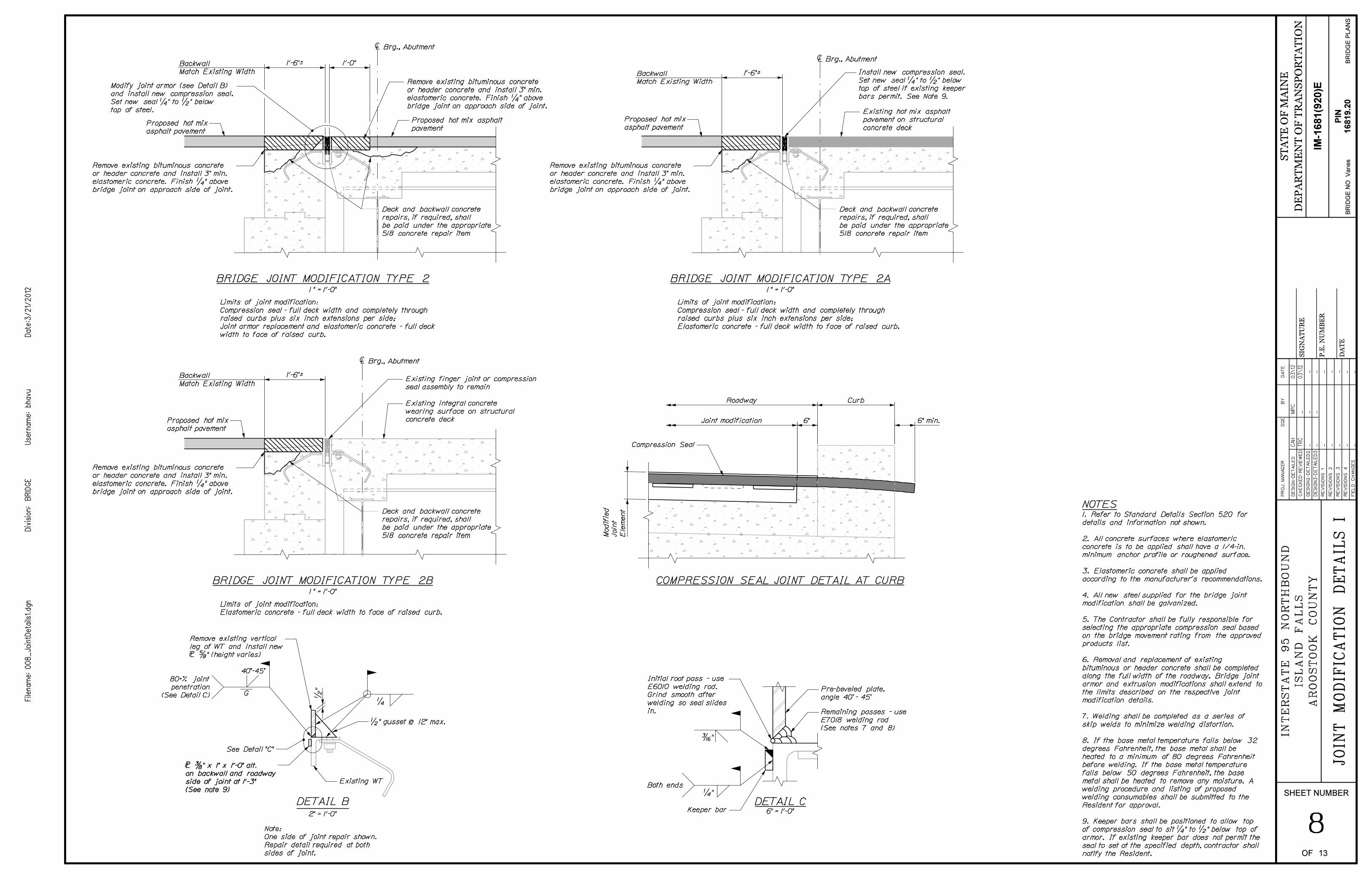
BRIDGE JOINT MODIFICATION TYPE 2
Backwall
Match Existing Width
É Brg., Abutment
1 " = 1’-0"
Backwall
Match Existing Width
BRIDGE JOINT MODIFICATION TYPE 2A
É Brg., Abutment
1 " = 1’-0"
Backwall
Match Existing Width
BRIDGE JOINT MODIFICATION TYPE 2B
NOTES
COMPRESSION SEAL JOINT DETAIL AT CURB
Limits of joint modification:
Compression seal - full deck width and completely through
raised curbs plus six inch extensions per side;
Joint armor replacement and elastomeric concrete - full deck
width to face of raised curb.
Limits of joint modification:
Elastomeric concrete - full deck width to face of raised curb.
Limits of joint modification:
Compression seal - full deck width and completely through
raised curbs plus six inch extensions per side;
Elastomeric concrete - full deck width to face of raised curb.
1. Refer to Standard Details Section 520 for
details and information not shown.
2. All concrete surfaces where elastomeric
concrete is to be applied shall have a 1/4-in.
minimum anchor profile or roughened surface.
3. Elastomeric concrete shall be applied
according to the manufacturer’s recommendations.
4. All new steel supplied for the bridge joint
modification shall be galvanized.
5. The Contractor shall be fully responsible for
selecting the appropriate compression seal based
on the bridge movement rating from the approved
products list.
6. Removal and replacement of existing
bituminous or header concrete shall be completed
along the full width of the roadway. Bridge joint
armor and extrusion modifications shall extend to
the limits described on the respective joint
modification details.
7. Welding shall be completed as a series of
skip welds to minimize welding distortion.
8. If the base metal temperature falls below 32
degrees Fahrenheit, the base metal shall be
heated to a minimum of 80 degrees Fahrenheit
before welding. If the base metal temperature
falls below 50 degrees Fahrenheit, the base
metal shall be heated to remove any moisture. A
welding procedure and listing of proposed
welding consumables shall be submitted to the
Resident for approval.
9. Keeper bars shall be positioned to allow top
of compression seal to sit 1/4 " to 1/2 " below top of
armor. If existing keeper bar does not permit the
seal to set at the specified depth, contractor shall
notify the Resident.
DETAIL C6" = 1’-0"
3/16 "
1/4 "
Both endsExisting WT
1/2 " gusset @ 12" max.
Remove existing vertical
leg of WT and install new
˚ 5/8 " (height varies)
See Detail "C"
˚ 3/8 " x 1" x 1’-0" alt.
on backwall and roadway
side of joint at 1’-3"
(See note 9)
1’-0"1’-6"¨
Proposed hot mix asphalt
pavementProposed hot mix
asphalt pavement
1’-6"¨
Proposed hot mix
asphalt pavement
1’-6"¨
Proposed hot mix
asphalt pavement
Existing integral concrete
wearing surface on structural
concrete deck
Modify joint armor (see Detail B)
and install new compression seal.
Set new seal 1/4 " to 1/2 " below
top of steel.
Remove existing bituminous concrete
or header concrete and install 3" min.
elastomeric concrete. Finish 1/4 " above
bridge joint on approach side of joint.
Remove existing bituminous concrete
or header concrete and install 3" min.
elastomeric concrete. Finish 1/4 " above
bridge joint on approach side of joint.
Remove existing bituminous concrete
or header concrete and install 3" min.
elastomeric concrete. Finish 1/4 " above
bridge joint on approach side of joint.
Remove existing bituminous concrete
or header concrete and install 3" min.
elastomeric concrete. Finish 1/4 " above
bridge joint on approach side of joint.
Existing finger joint or compression
seal assembly to remain
Existing hot mix asphalt
pavement on structural
concrete deck
Compression Seal
Roadway Curb
Joint modification 6" 6" min.
Install new compression seal.
Set new seal 1/4 " to 1/2 " below
top of steel if existing keeper
bars permit. See Note 9.
Deck and backwall concrete
repairs, if required, shall
be paid under the appropriate
518 concrete repair item
Deck and backwall concrete
repairs, if required, shall
be paid under the appropriate
518 concrete repair item
Deck and backwall concrete
repairs, if required, shall
be paid under the appropriate
518 concrete repair item
Pre-beveled plate,
angle 40^ - 45^
Keeper bar
Initial root pass - use
E6010 welding rod.
Grind smooth after
welding so seal slides
in. Remaining passes - use
E7018 welding rod
(See notes 7 and 8)
SHEET NUMBER
9OF 13
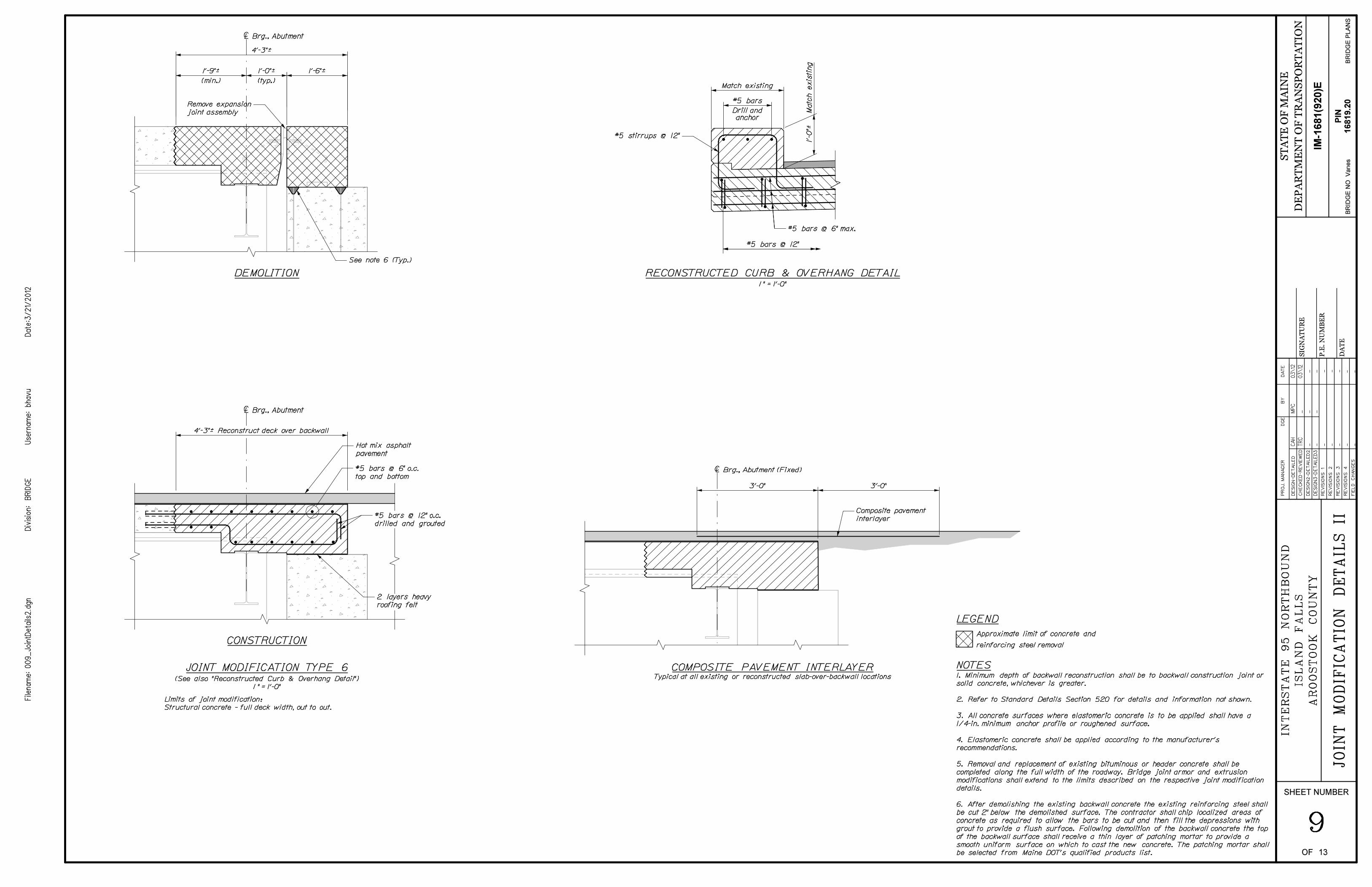
1 " = 1’-0"
RECONSTRUCTED CURB & OVERHANG DETAIL
anchor
#5 bars @ 12"
CONSTRUCTION
JOINT MODIFICATION TYPE 6
DEMOLITION
É Brg., Abutment
É Brg., Abutment
(See also "Reconstructed Curb & Overhang Detail")
1 " = 1’-0"
COMPOSITE PAVEMENT INTERLAYER
É Brg., Abutment (Fixed)
Typical at all existing or reconstructed slab-over-backwall locations
LEGEND
Approximate limit of concrete and
reinforcing steel removal
NOTES
Limits of joint modification:
Structural concrete - full deck width, out to out.
1. Minimum depth of backwall reconstruction shall be to backwall construction joint or
solid concrete, whichever is greater.
2. Refer to Standard Details Section 520 for details and information not shown.
3. All concrete surfaces where elastomeric concrete is to be applied shall have a
1/4-in. minimum anchor profile or roughened surface.
4. Elastomeric concrete shall be applied according to the manufacturer’s
recommendations.
5. Removal and replacement of existing bituminous or header concrete shall be
completed along the full width of the roadway. Bridge joint armor and extrusion
modifications shall extend to the limits described on the respective joint modification
details.
6. After demolishing the existing backwall concrete the existing reinforcing steel shall
be cut 2" below the demolished surface. The contractor shall chip localized areas of
concrete as required to allow the bars to be cut and then fill the depressions with
grout to provide a flush surface. Following demolition of the backwall concrete the top
of the backwall surface shall receive a thin layer of patching mortar to provide a
smooth uniform surface on which to cast the new concrete. The patching mortar shall
be selected from Maine DOT’s qualified products list.
Match existing
#5 stirrups @ 12"
#5 bars @ 6" max.
#5 bars
Drill andRemove expansion
joint assembly
#5 bars @ 12" o.c.
drilled and grouted
2 layers heavy
roofing felt
4’-3"¨ Reconstruct deck over backwall
4’-3"¨
Hot mix asphalt
pavement
#5 bars @ 6" o.c.
top and bottom
1’-6"¨
1’-0"¨
(typ.)
1’-9"¨
(min.)
3’-0"
Composite pavement
interlayer
See note 6 (Typ.)
SHEET NUMBER
10OF 13
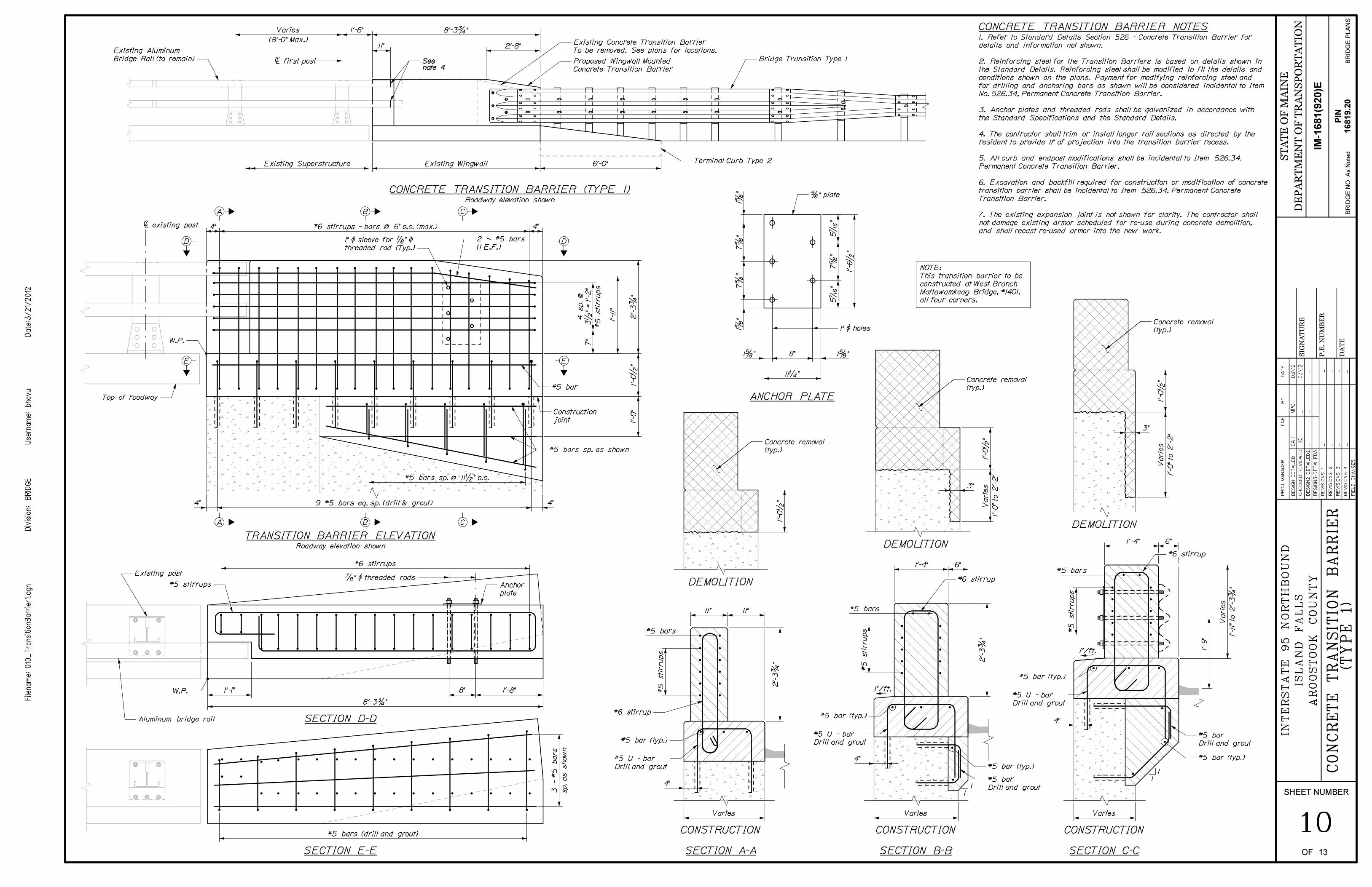
CONCRETE TRANSITION BARRIER NOTES
NOTE:
This transition barrier to be
constructed at West Branch
Mattawamkeag Bridge, #1401,
all four corners.
1. Refer to Standard Details Section 526 - Concrete Transition Barrier for
details and information not shown.
2. Reinforcing steel for the Transition Barriers is based on details shown in
the Standard Details. Reinforcing steel shall be modified to fit the details and
conditions shown on the plans. Payment for modifying reinforcing steel and
for drilling and anchoring bars as shown will be considered incidental to Item
No. 526.34, Permanent Concrete Transition Barrier.
3. Anchor plates and threaded rods shall be galvanized in accordance with
the Standard Specifications and the Standard Details.
4. The contractor shall trim or install longer rail sections as directed by the
resident to provide 11" of projection into the transition barrier recess.
5. All curb and endpost modifications shall be incidental to Item 526.34,
Permanent Concrete Transition Barrier.
6. Excavation and backfill required for construction or modification of concrete
transition barrier shall be incidental to Item 526.34, Permanent Concrete
Transition Barrier.
7. The existing expansion joint is not shown for clarity. The contractor shall
not damage existing armor scheduled for re-use during concrete demolition,
and shall recast re-used armor into the new work.
Roadway elevation shown
CONCRETE TRANSITION BARRIER (TYPE 1)
TRANSITION BARRIER ELEVATIONRoadway elevation shown
É existing post
B CA
A B C
DD
E E
SECTION D-D
SECTION E-E
ANCHOR PLATE
SECTION A-A
#5 bars
DEMOLITION
CONSTRUCTION
DEMOLITION
SECTION B-B
CONSTRUCTION
#5 bars
SECTION C-C
CONSTRUCTION
DEMOLITION
#5 bars
1
1
1
1
1"/ft.
1"/ft.
Bridge Transition Type 1
Terminal Curb Type 2
Existing Aluminum
Bridge Rail (to remain)
1’-6" 8’-3 3/4 "
6’-0"Existing Superstructure
2’-8"11"
Varies
(8’-0" Max.) Existing Concrete Transition Barrier
To be removed. See plans for locations.
Proposed Wingwall Mounted
Concrete Transition Barrier
Seenote 4
É first post
Existing Wingwall
1" Ì sleeve for 7/8 " Ì
threaded rod (Typ.)
4" #6 stirrups - bars @ 6" o.c. (max.) 4"
#5 bars sp. @ 11 1/2 " o.c.
2 ~ #5 bars
(1 E.F.)
#5 bars sp. as shown
Construction
joint
#5 bar
Top of roadway
4" 9 #5 bars eq. sp. (drill & grout) 4"
W.P.
8’-3 3/4 "
Aluminum bridge rail
1’-1" 8" 1’-8"
#5 stirrups
7/8 " Ì threaded rods
#6 stirrups
Existing post
Anchor
plate
#5 bars (drill and grout)
W.P.
11 1/4 "
8"1 5/8 " 1 5/8 "
5/8 " plate
1" Ì holes
#5 U - bar
Drill and grout
#5 bar (typ.)
#6 stirrup
#5 bar (typ.)
#5 U - bar
Drill and grout
#5 bar (typ.)
#5 bar
Drill and grout
#5 U - bar
Drill and grout
#5 bar (typ.)
#5 bar (typ.)
#5 bar
Drill and grout
Concrete removal
(typ.)
Concrete removal
(typ.)
3"
Concrete removal
(typ.)
3"
Varies Varies Varies
#6 stirrup
#6 stirrup
4"
4"
4"
11" 11"
1’-4" 6"
1’-4" 6"
SHEET NUMBER
11OF 13
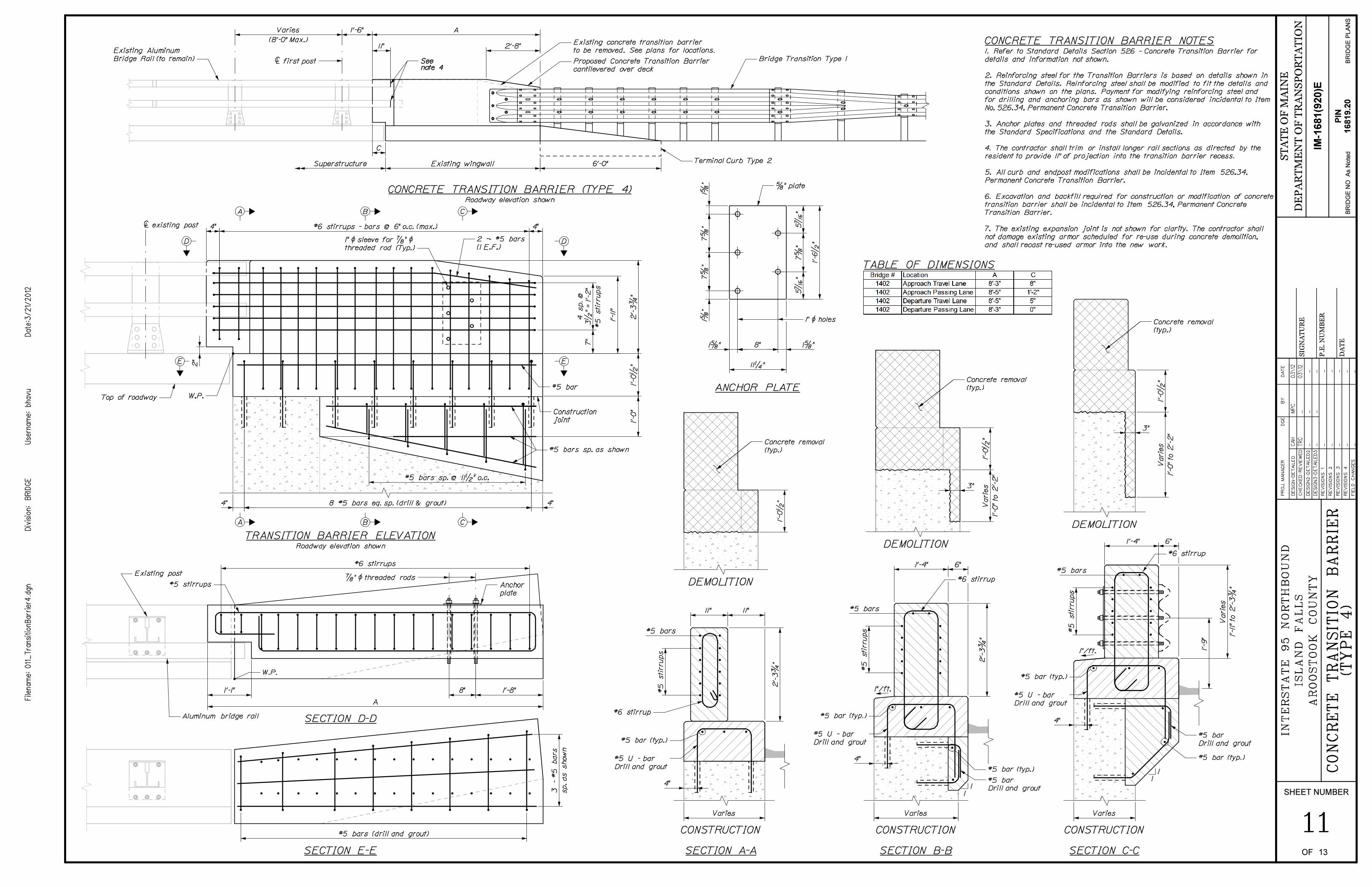
CONCRETE TRANSITION BARRIER NOTES
TABLE OF DIMENSIONS
1. Refer to Standard Details Section 526 - Concrete Transition Barrier for
details and information not shown.
2. Reinforcing steel for the Transition Barriers is based on details shown in
the Standard Details. Reinforcing steel shall be modified to fit the details and
conditions shown on the plans. Payment for modifying reinforcing steel and
for drilling and anchoring bars as shown will be considered incidental to Item
No. 526.34, Permanent Concrete Transition Barrier.
3. Anchor plates and threaded rods shall be galvanized in accordance with
the Standard Specifications and the Standard Details.
4. The contractor shall trim or install longer rail sections as directed by the
resident to provide 11" of projection into the transition barrier recess.
5. All curb and endpost modifications shall be incidental to Item 526.34,
Permanent Concrete Transition Barrier.
6. Excavation and backfill required for construction or modification of concrete
transition barrier shall be incidental to Item 526.34, Permanent Concrete
Transition Barrier.
7. The existing expansion joint is not shown for clarity. The contractor shall
not damage existing armor scheduled for re-use during concrete demolition,
and shall recast re-used armor into the new work.
Roadway elevation shown
CONCRETE TRANSITION BARRIER (TYPE 4)
TRANSITION BARRIER ELEVATIONRoadway elevation shown
É existing post
B CA
A B C
DD
E E
SECTION D-D
SECTION E-E
ANCHOR PLATE
SECTION A-A
#5 bars
DEMOLITION
CONSTRUCTION
DEMOLITION
SECTION B-B
CONSTRUCTION
#5 bars
SECTION C-C
CONSTRUCTION
DEMOLITION
#5 bars
1"/ft.
1"/ft.
1
1
1
1
Bridge Transition Type 1
Terminal Curb Type 2
Existing Aluminum
Bridge Rail (to remain)
1’-6" A
6’-0"
2’-8"11"
Varies
(8’-0" Max.) Existing concrete transition barrier
to be removed. See plans for locations.
Seenote 4
É first post Proposed Concrete Transition Barrier
cantilevered over deck
C
Existing wingwallSuperstructure
1" Ì sleeve for 7/8 " Ì
threaded rod (Typ.)
4" #6 stirrups - bars @ 6" o.c. (max.) 4"
#5 bars sp. @ 11 1/2 " o.c.
2 ~ #5 bars
(1 E.F.)
8 #5 bars eq. sp. (drill & grout)
#5 bars sp. as shown
Construction
joint
W.P.
#5 bar
4"4"
Top of roadway
A
Aluminum bridge rail
1’-1" 8" 1’-8"
#5 stirrups
7/8 " Ì threaded rods
#6 stirrups
Existing post
Anchor
plate
#5 bars (drill and grout)
W.P.
11 1/4 "
8"1 5/8 " 1 5/8 "
5/8 " plate
1" Ì holes
#5 U - bar
Drill and grout
#5 bar (typ.)
#6 stirrup
#5 bar (typ.)
#5 U - bar
Drill and grout
#5 bar (typ.)
#5 bar
Drill and grout
#5 U - bar
Drill and grout
#5 bar (typ.)
#5 bar (typ.)
#5 bar
Drill and grout
Concrete removal
(typ.)
Concrete removal
(typ.)
3"
Concrete removal
(typ.)
3"
#6 stirrup
#6 stirrup
Varies Varies Varies
4"
4"
4"
11" 11"
1’-4" 6"
1’-4" 6"
SHEET NUMBER
12OF 13
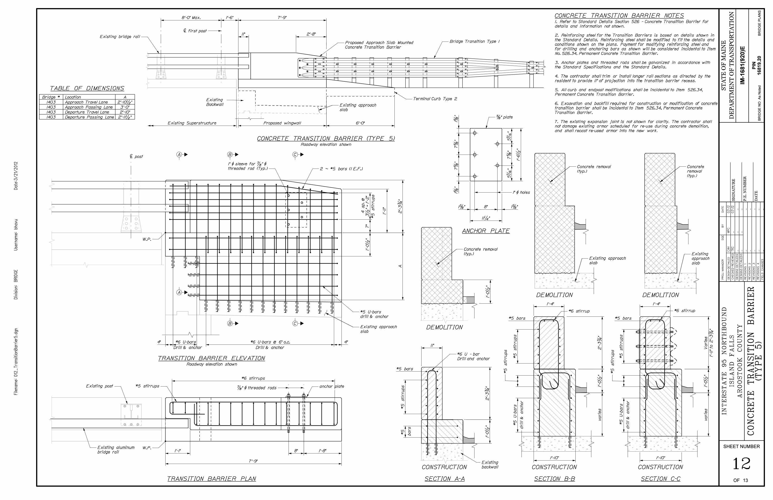
CONCRETE TRANSITION BARRIER NOTES
TABLE OF DIMENSIONS
1. Refer to Standard Details Section 526 - Concrete Transition Barrier for
details and information not shown.
2. Reinforcing steel for the Transition Barriers is based on details shown in
the Standard Details. Reinforcing steel shall be modified to fit the details and
conditions shown on the plans. Payment for modifying reinforcing steel and
for drilling and anchoring bars as shown will be considered incidental to Item
No. 526.34, Permanent Concrete Transition Barrier.
3. Anchor plates and threaded rods shall be galvanized in accordance with
the Standard Specifications and the Standard Details.
4. The contractor shall trim or install longer rail sections as directed by the
resident to provide 11" of projection into the transition barrier recess.
5. All curb and endpost modifications shall be incidental to Item 526.34,
Permanent Concrete Transition Barrier.
6. Excavation and backfill required for construction or modification of concrete
transition barrier shall be incidental to Item 526.34, Permanent Concrete
Transition Barrier.
7. The existing expansion joint is not shown for clarity. The contractor shall
not damage existing armor scheduled for re-use during concrete demolition,
and shall recast re-used armor into the new work.
Bridge #
1403
1403
1403
1403
Location
Approach Travel Lane
Approach Passing Lane
Departure Travel Lane
Departure Passing Lane
A
2’-10 1/2 "
3’-0"
2’-10"
2’-11 1/2 "
TRANSITION BARRIER ELEVATIONRoadway elevation shown
A
A B
B
C
C
TRANSITION BARRIER PLAN
Drill & anchor
É post
Drill & anchor
#5 bars
Existing
backwall
#5 bars #5 bars
SECTION A-A
CONSTRUCTION
SECTION B-B
CONSTRUCTION
SECTION C-C
CONSTRUCTION
DEMOLITION
DEMOLITION DEMOLITION
ANCHOR PLATE
Roadway elevation shown
CONCRETE TRANSITION BARRIER (TYPE 5)
2 ~ #5 bars (1 E.F.)
1" Ì sleeve for 7/8 " Ì
threaded rod (Typ.)
W.P.
#5 stirrups
7’-9"
anchor plate 7/8 " Ì threaded rods
1’-1" 8" 1’-8"
#6 stirrups
#6 U-bars
#5 U-bars
drill & anchor
W.P.
4"
Existing post
Existing approach
slab
#6 U-bars @ 6" o.c. 4"
Existing aluminum
bridge rail
11"
#6 U - bar
Drill and anchor
1’-4"
#6 stirrup
1’-4"
#6 stirrup
1’-10" 1’-10"
Concrete removal
(typ.)
Concrete removal
(typ.)
Concrete
removal
(typ.)
Existing approach
slab
Existing
approach
slab
11 1/4 "
8"1 5/8 " 1 5/8 "
5/8 " plate
1" Ì holes
Bridge Transition Type 1
Terminal Curb Type 2
1’-6" 7’-9"
6’-0"Proposed wingwallExisting Superstructure
2’-8"11"
8’-0" Max.
Existing
Backwall
Existing bridge rail
Proposed Approach Slab Mounted
Concrete Transition Barrier
Existing approach
slab
É first post
SHEET NUMBER
OF 13
13
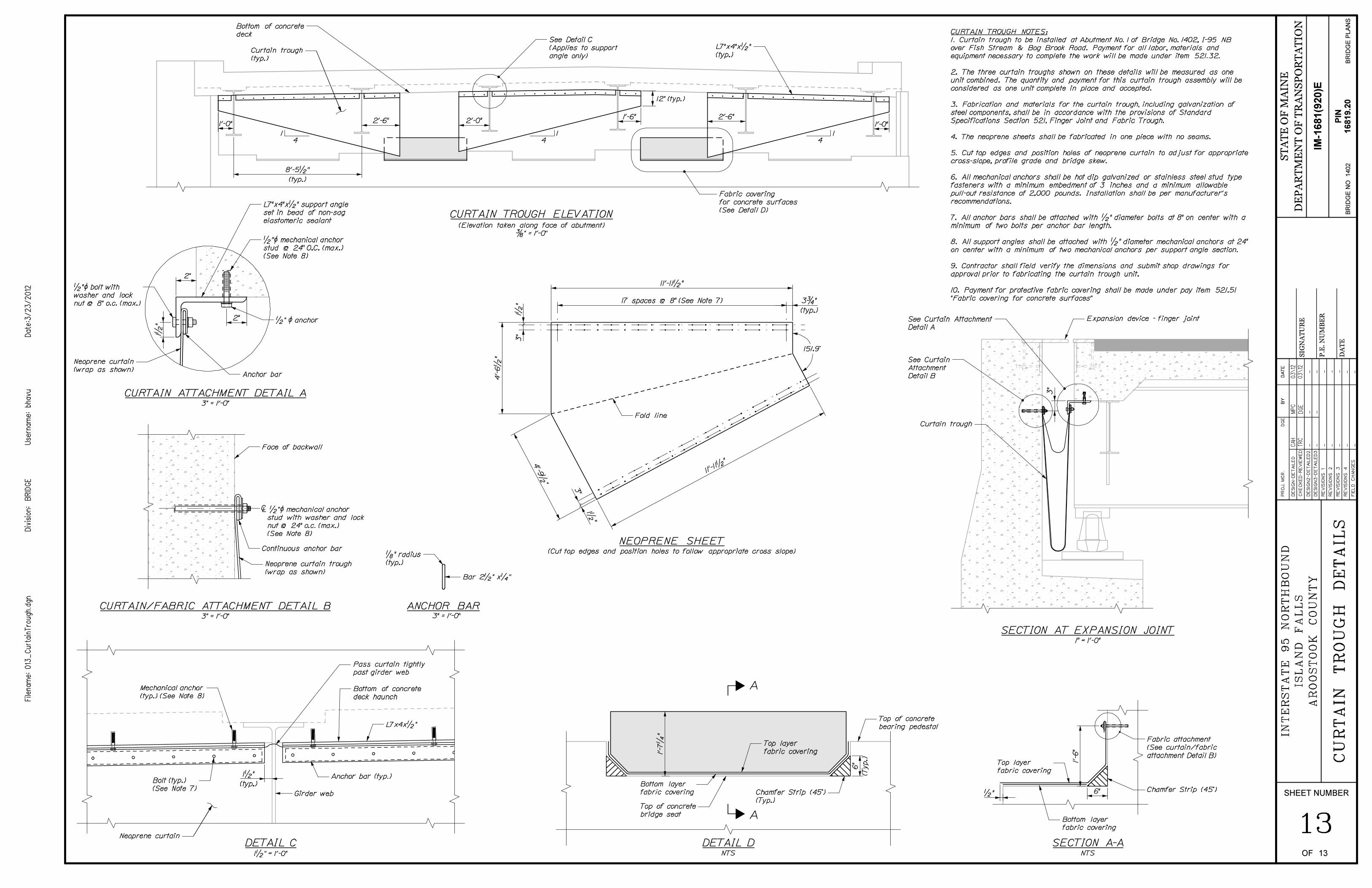
SECTION AT EXPANSION JOINT1" = 1’-0"
3" = 1’-0"
É 1/2 "Ì mechanical anchor
stud with washer and lock
nut @ 24" o.c. (max.)
(See Note 8)
CURTAIN/FABRIC ATTACHMENT DETAIL B
CURTAIN TROUGH ELEVATION
(Elevation taken along face of abutment)
3/8 " = 1’-0"
NTS
DETAIL D
12" (typ.)
1
4
1
4
1
4
A
A
Fabric covering
for concrete surfaces
(See Detail D)
CURTAIN TROUGH NOTES:
1. Curtain trough to be installed at Abutment No. 1 of Bridge No. 1402, I-95 NB
over Fish Stream & Bog Brook Road. Payment for all labor, materials and
equipment necessary to complete the work will be made under item 521.32.
2. The three curtain troughs shown on these details will be measured as one
unit combined. The quantity and payment for this curtain trough assembly will be
considered as one unit complete in place and accepted.
3. Fabrication and materials for the curtain trough, including galvanization of
steel components, shall be in accordance with the provisions of Standard
Specifications Section 521, Finger Joint and Fabric Trough.
4. The neoprene sheets shall be fabricated in one piece with no seams.
5. Cut top edges and position holes of neoprene curtain to adjust for appropriate
cross-slope, profile grade and bridge skew.
6. All mechanical anchors shall be hot dip galvanized or stainless steel stud type
fasteners with a minimum embedment of 3 inches and a minimum allowable
pull-out resistance of 2,000 pounds. Installation shall be per manufacturer’s
recommendations.
7. All anchor bars shall be attached with 1/2 " diameter bolts at 8" on center with a
minimum of two bolts per anchor bar length.
8. All support angles shall be attached with 1/2 " diameter mechanical anchors at 24"
on center with a minimum of two mechanical anchors per support angle section.
9. Contractor shall field verify the dimensions and submit shop drawings for
approval prior to fabricating the curtain trough unit.
10. Payment for protective fabric covering shall be made under pay item 521.51
"Fabric covering for concrete surfaces"
ANCHOR BAR3" = 1’-0"
3" = 1’-0"
CURTAIN ATTACHMENT DETAIL A
NEOPRENE SHEET(Cut top edges and position holes to follow appropriate cross slope)
DETAIL C1 1/2 " = 1’-0" NTS
DETAIL D
A
A
SECTION A-ANTS
Expansion device - finger joint
Curtain trough
See Curtain Attachment
Detail A
See Curtain
Attachment
Detail B
Face of backwall
Continuous anchor bar
Neoprene curtain trough
(wrap as shown)
Bottom layer
fabric covering
Bottom of concrete
deckSee Detail C
(Applies to support
angle only)
Chamfer Strip (45^)
(Typ.)
L7"x4"x 1/2 "
(typ.)Curtain trough
(typ.)
1’-6"
1’-0"2’-6" 2’-0"
2’-6"
1’-0"
8’-5 1/2 "
(typ.)
Top of concrete
bridge seat
Top of concrete
bearing pedestal
Top layer
fabric covering
Bar 2 1/2 " x 1/4 "
1/8 " radius
(typ.)
1/2 " Ì anchor
Neoprene curtain
(wrap as shown)
2"
2"
1/2 "Ì bolt with
washer and lock
nut @ 8" o.c. (max.)
Anchor bar
L7"x4"x 1/2 " support angle
set in bead of non-sag
elastomeric sealant
1/2 "Ì mechanical anchor
stud @ 24" O.C. (max.)
(See Note 8)
11’-11 1/2 "
Fold line
151.9^
3 3/4 "
(typ.)
17 spaces @ 8" (See Note 7)
1 1/2 "
(typ.)
Girder web
Anchor bar (typ.)
Bottom of concrete
deck haunch
L7x4x 1/2 "
Neoprene curtain
Pass curtain tightly
past girder web
Mechanical anchor
(typ.) (See Note 8)
Bolt (typ.)
(See Note 7)Bottom layer
fabric covering Chamfer Strip (45^)
(Typ.)Top of concrete
bridge seat
Top of concrete
bearing pedestal
Top layer
fabric covering
Top layer
fabric covering
Bottom layer
fabric covering
Chamfer Strip (45^)
Fabric attachment
(See curtain/fabric
attachment Detail B)
6" 1/2 "