Embed Size (px)
Citation preview

Shear Joints with Eccentric Loading
Integral to the analysis of a shear joint is locating the center of
relative motion between the two members. In Fig. (5–17) let A1 to A5
be the respective cross-sectional areas of a group of five pins, or hot-
driven rivets, or tight-fitting shoulder bolts. Under this assumption
the rotational pivot point lies at the centroid of the cross-sectional
area pattern of the pins, rivets, or bolts. Using statics, we learn that
the centroid G is located by the coordinates
are the distances to the ith
area center:
x and y , where xi and yi
Figure (5–17) Centroid of pins, rivets, or bolts
5-17
In many instances the centroid can be located by symmetry. An example of eccentric loading of fasteners is shown in Fig.
(5–18). This is a portion of a machine frame containing a beam
subjected to the action of a bending load. In this case, the beam is

fastened to vertical members at the ends with specially prepared
load-sharing bolts. You will recognize the schematic representation
in Fig. (5–18b) as a statically indeterminate beam with both ends
fixed and with moment and shear reactions at each end.
Figure (5–18)
(a) Beam bolted at both ends with distributed load; (b) free-body diagram of
beam; (c) enlarged view of bolt group centered at O showing primary
and secondary resultant shear forces
For convenience, the centers of the bolts at the left end of the beam
are drawn to a larger scale in Fig. (5–18c). Point O represents the
centroid of the group, and it is assumed in this example that all the
bolts are of the same diameter. Note that the forces shown in Fig. (5–
18c) are the resultant forces acting on the pins with a net force and
moment equal and opposite to the reaction loads V1 and M1

acting at O. The total load taken by each bolt will be calculated in
three steps. In the first step the shear V1 is divided equally among the
bolts so that each bolt takes F′ = V1/n, where n refers to the number
of bolts in the group and the force F′ is called the direct load, or
primary shear. It is noted that an equal distribution of the direct load
to the bolts assumes an absolutely rigid member. The arrangement of
the bolts or the shape and size of the members sometimes justifies
the use of another assumption as to the division of the load. The
direct loads F′ are shown as vectors on the loading diagram
(Fig. 5–18c).
The moment load, or secondary shear, is the additional load
on each bolt due to the moment M1. If rA, rB, rC , etc., are the radial
distances from the centroid to the center of each bolt, the moment
and moment loads are related as follows:
a
a
where the F′′ are the moment loads. The force taken by each bolt
depends upon its radial distance from the centroid; that is, the bolt
farthest from the centroid takes the greatest load, while the nearest
bolt takes the smallest. We can therefore write
b
where again, the diameters of the bolts are assumed equal. If not,
then one replaces F′′ in Eq. (b) with the shear stresses τ′′ = 4F′′/πd2
for each bolt. Solving Eqs. (a) and (b) simultaneously, we obtain:
5-18
5
where the subscript n refers to the particular bolt whose load is to be
found. These moment loads are also shown as vectors on the
loading diagram.
In the third step the direct and moment loads are added
vectorially to obtain the resultant load on each bolt. Since all the
bolts or rivets are usually the same size, only that bolt having the
maximum load need be considered. When the maximum load is
found, the strength may be determined by using the various methods
already described.

EXAMPLE 5–3
Shown in figure is a 15- by 200-mm rectangular steel bar
cantilevered to a 250-mm steel channel using four tightly fitted bolts
located at A, B, C, and D. For a load of F = 16 kN, find
(a) The resultant load on each bolt
(b) The maximum shear stress in each bolt
(c) The maximum bearing stress (d) The critical bending stress in the bar
Solution
(a) Point O, the centroid of the bolt group, is found by symmetry. If
a free-body diagram of the beam were constructed, the shear
reaction V would pass through O and the moment reactions M would
be about O. These reactions are
V = 16 kN M = 16(425) = 6800 N·m
In the following figure, the bolt group has been drawn to a
larger scale and the reactions are shown.
Dimensions in millimeters

The distance from the centroid to the center of each bolt is
r = [(60)2 + (75)
2]
1/2 = 96 mm
The primary shear load per bolt is
Since the secondary shear forces are equal, Eq.
(5–19) becomes
The primary and secondary shear forces are plotted to scale and the
resultants obtained by using the parallelogram rule. The magnitudes
are found by measurement (or analysis) to be
FA = FB = 21.0 kN
FC = FD = 14.8 kN
(HW)
(b) Bolts A and B are critical because they carry the largest shear

load. Does this shear act on the threaded portion of the bolt, or on

the unthreaded portion? The bolt length will be 25 mm plus the
height of the nut plus about 2 mm for a washer. From net-tables, the
nut height is 14.8 mm. Including two threads beyond the nut, this
adds up to a length of 43.8 mm, and so a bolt 46 mm long will be
needed. From Eq. (5–12) we compute the thread length as
LT = 38 mm. Thus the unthreaded portion of the bolt is
46 − 38 = 8 mm long. This is less than the 15 mm for the plate in
Fig. 8–28, and so the bolt will tend to shear across its minor
diameter. Therefore, from table (5–1), the shear-stress area is
As = 144 mm2, and so the shear stress is
(c) The channel is thinner than the bar, and so the largest bearing
stress is due to the pressing of the bolt against the channel web. The
bearing area is Ab = td = 10(16) = 160 mm2. Thus the bearing
stress is
(d) The critical bending stress in the bar is assumed to occur in a
section parallel to the y axis and through bolts A and B. At this
section the bending moment is
M = 16(300 + 50) = 5600 N·m
The second moment of area through this section is obtained by the
use of the transfer formula, as follows:
Then:
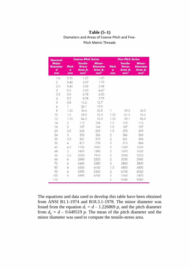
Table (5–1) Diameters and Areas of Coarse-Pitch and Fine-
Pitch Metric Threads
The equations and data used to develop this table have been obtained
from ANSI B1.1-1974 and B18.3.1-1978. The minor diameter was
found from the equation dr = d – 1.226869 p, and the pitch diameter
from dp = d – 0.649519 p. The mean of the pitch diameter and the
minor diameter was used to compute the tensile-stress area.
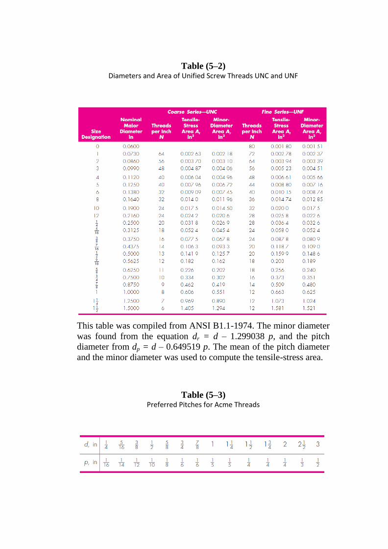
Table (5–2) Diameters and Area of Unified Screw Threads UNC and UNF
This table was compiled from ANSI B1.1-1974. The minor diameter
was found from the equation dr = d – 1.299038 p, and the pitch
diameter from dp = d – 0.649519 p. The mean of the pitch diameter
and the minor diameter was used to compute the tensile-stress area.
Table (5–3)
Preferred Pitches for Acme Threads

Table (5–4) SAE Specifications for Steel Bolts
*Minimum strengths are strengths exceeded by 99 percent of
fasteners.

Table (5–5) ASTM Specifications for Steel Bolts
*Minimum
fasteners. strengths are strengths exceeded by 99 percent of

Table (5–6) Metric Mechanical-Property Classes for Steel Bolts, Screws, and Studs*
*The thread length for bolts and cap screws is
where L is the bolt length. The thread length for structural bolts is
slightly shorter than given above.
Minimum
fasteners. strengths are strength exceeded by 99 percent of
4
16
Homework
(1) A power screw is 25 mm in diameter and has a thread pitch of
5 mm. (a) Find the thread depth, the thread width, the mean and root
diameters, and the lead, provided square threads are used. (b) Repeat
part (a) for Acme threads.
(2) Show that for zero collar friction the efficiency of a square-
thread screw is given by the equation
(3) A single-threaded power screw is 25 mm in diameter with a pitch
of 5 mm. A vertical load on the screw reaches a maximum of 6 kN.
The coefficients of friction are 0.05 for the collar and 0.08 for the
threads. The frictional diameter of the collar is 40 mm. Find
overall efficiency and the torque to “raise” and “lower” the load. the
(Ans./ 0.294, 16.23 N.m, 6.622 N.m )
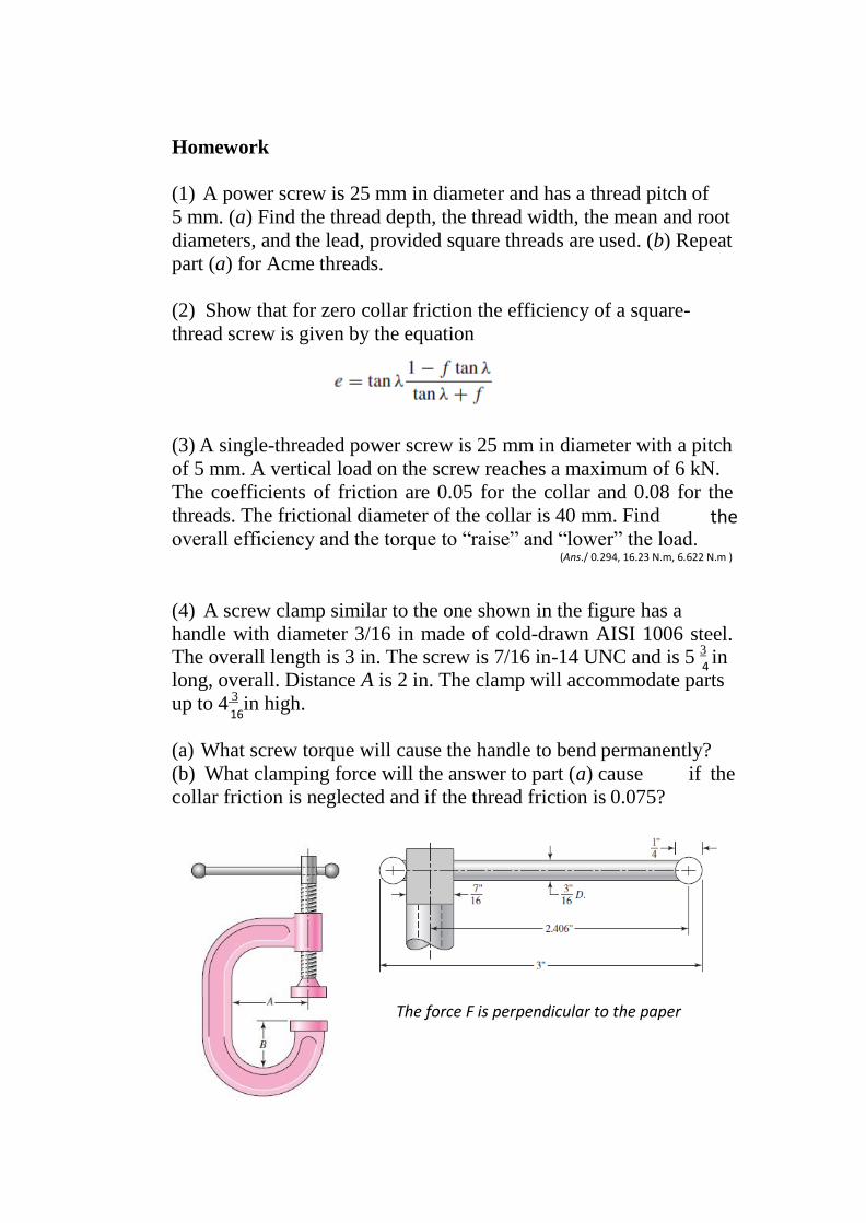
(4) A screw clamp similar to the one shown in the figure has a
handle with diameter 3/16 in made of cold-drawn AISI 1006 steel. The overall length is 3 in. The screw is 7/16 in-14 UNC and is 5
3 in
long, overall. Distance A is 2 in. The clamp will accommodate parts
up to 4 3 in high.
(a) What screw torque will cause the handle to bend permanently?
(b) What clamping force will the answer to part (a) cause
collar friction is neglected and if the thread friction is 0.075?
if the
The force F is perpendicular to the paper

(5) Find the power required to drive a 40-mm power screw having
double square threads with a pitch of 6 mm. The nut is to move at a
velocity of 48 mm/s and move a load of F = 10 kN. The frictional
coefficients are 0.1 for the threads and 0.15 for the collar. The
frictional diameter of the collar is 60 mm. (Ans./ 2.086 kW)
(6) A single square-thread power screw has an input power of 3 kW
at a speed of 1 rev/s. The screw has a diameter of 36 mm and a pitch
of 6 mm. The frictional coefficients are 0.14 for the threads and 0.09
for the collar, with a collar friction radius of 45 mm. Find the axial
resisting load F and the combined efficiency of the screw and collar. (Ans./ 65 kN, 0.13)
(7) The figure shows a bolted lap joint that uses SAE grade 8 bolts.
The members are made of cold-drawn AISI 1040 steel. Find the safe
tensile shear load F that can be applied to this connection if the
following factors of safety are specified: shear of bolts 3, bearing on
bolts 2, bearing on members 2.5, and tension of members 3. (Ans./ 5.18 kip)
(8) The bolted connection shown in the figure uses SAE grade 5
bolts. The members are hot-rolled AISI 1018 steel. A tensile shear
load F = 4000 lbf is applied to the connection. Find the factor of
safety for all possible modes of failure. (Ans./ 2.93, 4.32, 1.5, 3.25)

(9) A bolted lap joint using SAE grade 5 bolts and members made of
cold-drawn SAE 1040 steel is shown in the figure. Find the tensile
shear load F that can be applied to this connection if the following
factors of safety are specified: shear of bolts 1.8, bearing on bolts
2.2, bearing on members 2.4, and tension of members 2.6. (Ans./ 35.46)
(10) The bolted connection shown in the figure is subjected to a
tensile shear load of 20 kip. The bolts are SAE grade 5 and the
material is cold-drawn AISI 1015 steel. Find the factor of safety of
the connection for all possible modes of failure. (Ans./ 3.52, 6.47, 3.31, 7.71)
(11) The figure shows a connection that employs three SAE grade 5
bolts. The tensile shear load on the joint is 5400 lbf. The members
are cold-drawn bars of AISI 1020 steel. Find the factor of safety for
each possible mode of failure. (Ans./ 3.26, 5.99, 3.71, 5.36)

(12) A beam is made up by bolting together two cold-drawn bars of
AISI 1018 steel as a lap joint, as shown in the figure. The bolts used
are ISO 5.8. Ignoring any twisting, determine the factor of safety of
the connection. (Ans./ n = the minimum of (2.72, 5.29, 3.15) = 2.72)
(13) A vertical channel 152 × 76 (t = 6.4 mm) has a cantilever beam
bolted to it as shown. The channel is hot-rolled AISI 1006 steel.
The bar is of hot-rolled AISI 1015 steel. The shoulder bolts are
M12 × 1.75 ISO 5.8. For a design factor of 2.8, find the safe force
F that can be applied to the cantilever. (Ans./ F = 1.99 kN based on bearing on channel)
(14) Find the total shear load on each of the three bolts for the
connection shown in the figure and compute the significant bolt
shear stress and bearing stress. Find the second moment of area of
the 8-mm plate on a section through the three bolt holes, and find the
maximum bending stress in the plate. (Ans./ 1.48(10)6 mm4, 110 MPa )
Dimensions in
millimeters
Dimensions in millimeters
Dimensions in millimeters
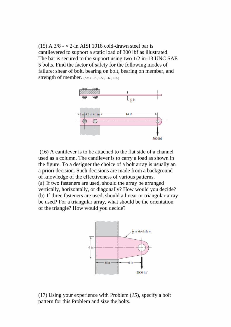
(15) A 3/8 - × 2-in AISI 1018 cold-drawn steel bar is
cantilevered to support a static load of 300 lbf as illustrated.
The bar is secured to the support using two 1/2 in-13 UNC SAE
5 bolts. Find the factor of safety for the following modes of
failure: shear of bolt, bearing on bolt, bearing on member, and
strength of member. (Ans./ 5.79, 9.58, 5.63, 2.95)
(16) A cantilever is to be attached to the flat side of a channel
used as a column. The cantilever is to carry a load as shown in
the figure. To a designer the choice of a bolt array is usually an
a priori decision. Such decisions are made from a background
of knowledge of the effectiveness of various patterns.
(a) If two fasteners are used, should the array be arranged
vertically, horizontally, or diagonally? How would you decide?
(b) If three fasteners are used, should a linear or triangular array
be used? For a triangular array, what should be the orientation
of the triangle? How would you decide?
(17) Using your experience with Problem (15), specify a bolt
pattern for this Problem and size the bolts.
![IS 12608 (1989): rock joints-direct shear strength ...IS 12608 (1989): rock joints-direct shear strength-laboratory method of determination [CED 48: Rock Mechanics] METHODFOR ... 3.1.1](https://img.pdfslide.us/doc/110x75/5e6de58548a3964b42128b08/is-12608-1989-rock-joints-direct-shear-strength-is-12608-1989-rock-joints-direct.jpg)