Embed Size (px)
Citation preview
Shale Oils – Designing for Improved Crude Preheat Train Reliability and PerformanceShale Oils – Designing for Improved Crude Preheat Train Reliability and Performance
Dominic Varraveto, PE
Chief Process Engineer & Director of Technology
Mark W. Lockhart, PE
Process Technology Manager, Refining & Chemicals
Abyar Aejaz, EIT
Senior Process Engineer, Process Group
RefComm Conference 2015Galveston, Texas
May 4 - 8, 2015
Introduction / Overview
• Shale plays – locations and current production
• Tight oil and condensate – composition
• Design approach for crude preheat train design
• Exchanger fouling and design
• Desalter design and operation
• Flash drum placement and design
• Crude charge heater fouling and design
• Conclusions
2
3
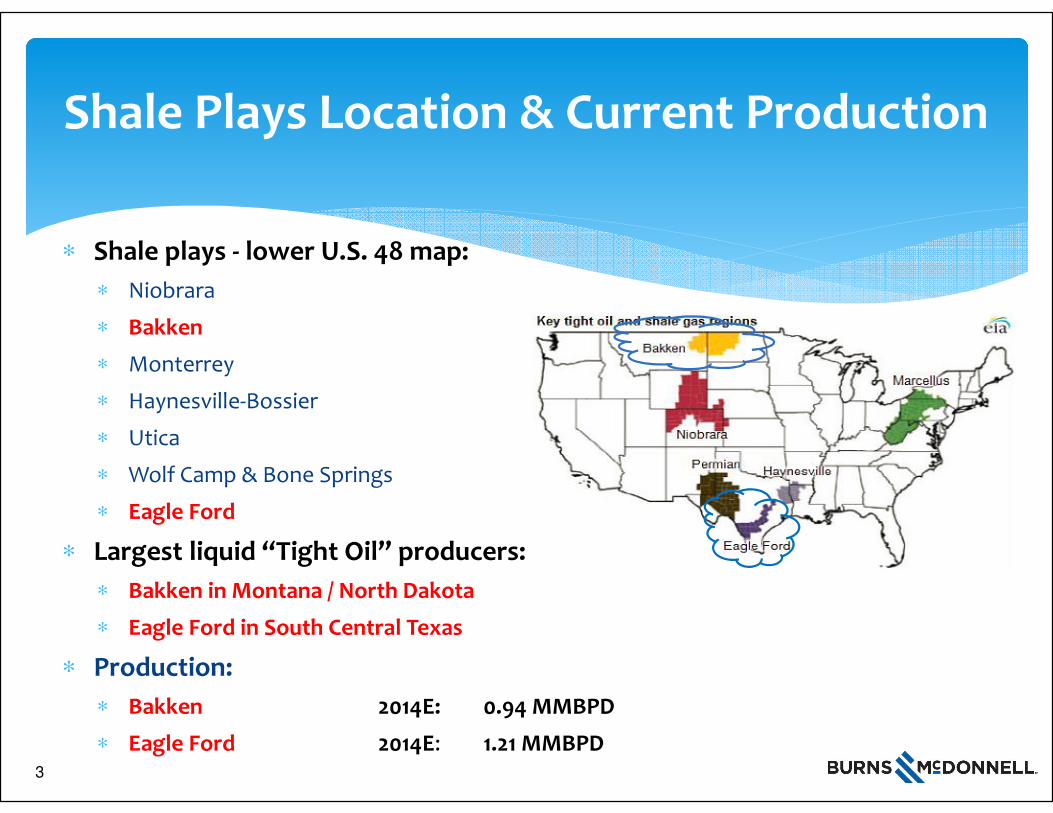
Shale Plays Location & Current Production
∗ Shale plays - lower U.S. 48 map:
∗ Niobrara
∗ Bakken
∗ Monterrey
∗ Haynesville-Bossier
∗ Utica
∗ Wolf Camp & Bone Springs
∗ Eagle Ford
∗ Largest liquid “Tight Oil” producers:
∗ Bakken in Montana / North Dakota
∗ Eagle Ford in South Central Texas
∗ Production:
∗ Bakken 2014E: 0.94 MMBPD
∗ Eagle Ford 2014E: 1.21 MMBPD3
4
Tight Oil & Condensate Composition
∗ Tight oil and condensate are:
∗ Light and sweet
∗ Sulfur: < 0.25 wt%
∗ High naphtha content
∗ Paraffinic
∗ Heavy metals are low
∗ High filterable solids
∗ Tight Oil: ~ 40 – 55 API gravity
∗ Condensate: ~ 55 – 65 API gravity
∗ Processing Challenges from:
∗ Paraffinic nature – wax deposition, asphaltene precipitation when blend crudes, exchanger and charge heater fouling
∗ Filterable solids – exchanger and fired heater fouling
∗ Refiners lack of ability to clean equipment on-line
Source: AFPM AM-14-17, 2014
4
5
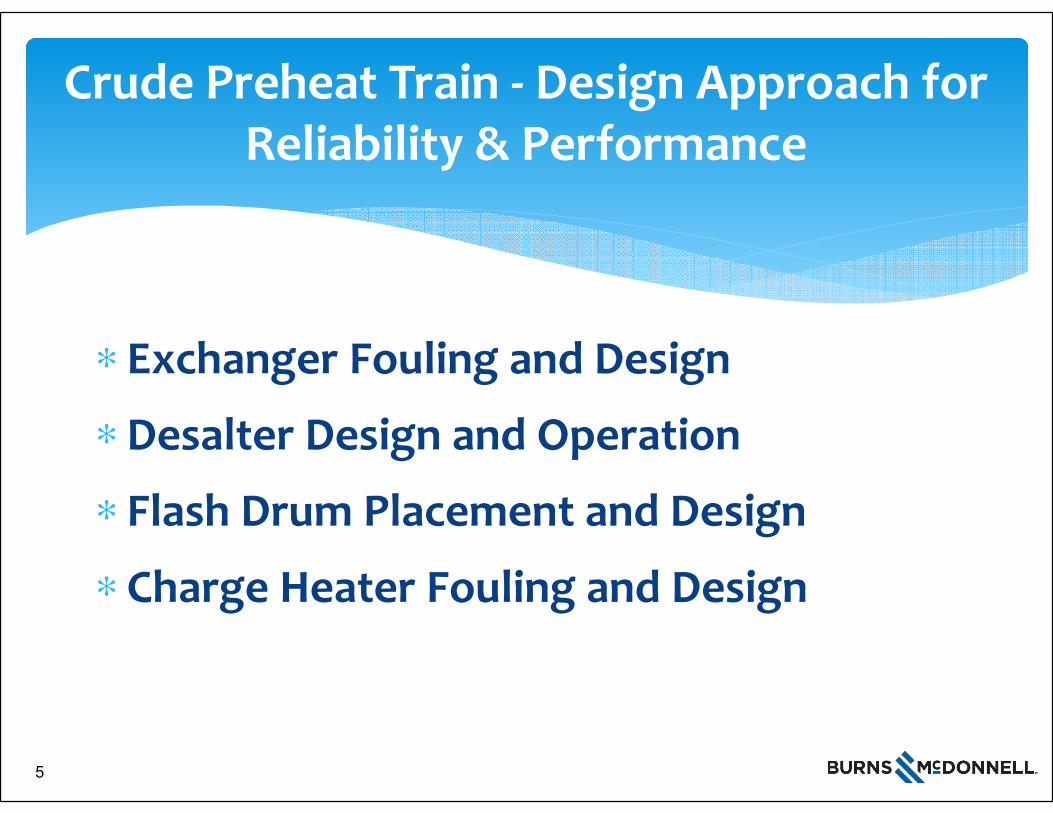
Crude Preheat Train - Design Approach for Reliability & Performance
∗ Exchanger Fouling and Design
∗ Desalter Design and Operation
∗ Flash Drum Placement and Design
∗ Charge Heater Fouling and Design
5
6
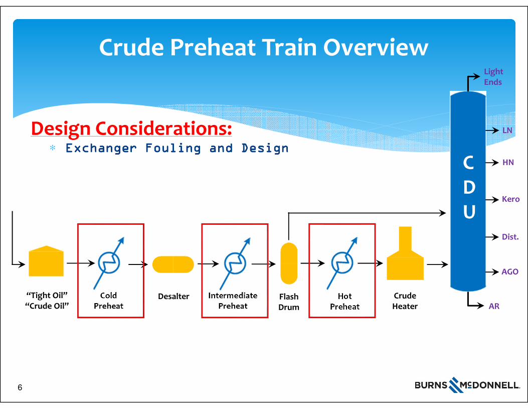
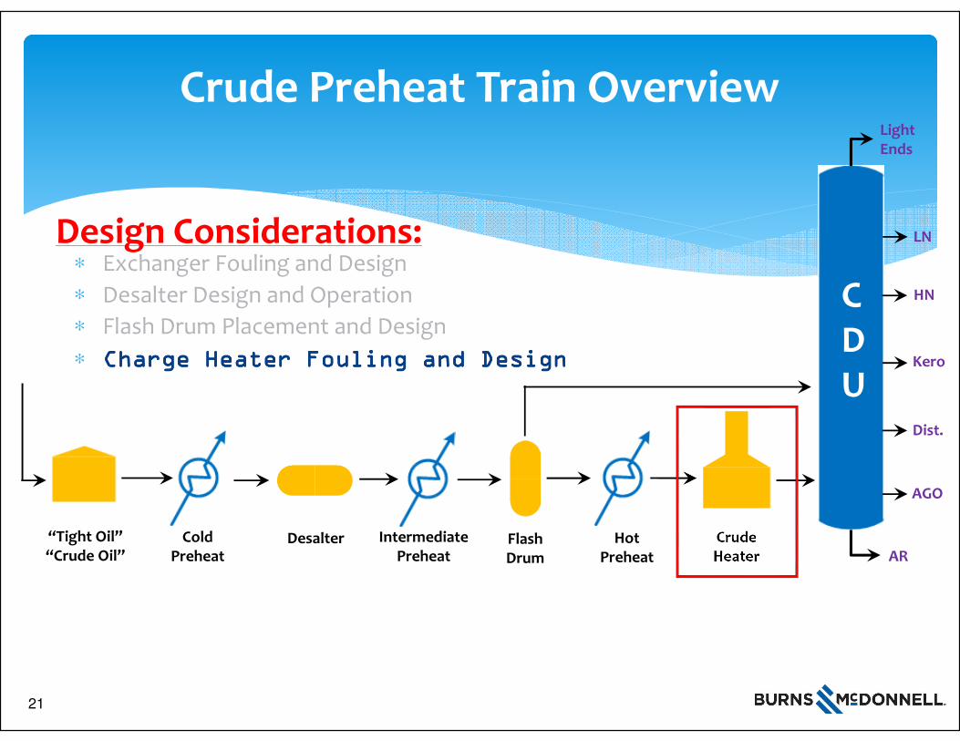
Crude Preheat Train Overview
∗ Exchanger Fouling and DesignExchanger Fouling and DesignExchanger Fouling and DesignExchanger Fouling and Design
“Tight Oil”“Crude Oil”
Cold Preheat
Hot Preheat
DesalterAR
AGO
LightEnds
LN
HN
Kero
Dist.
CDU
Crude Heater
Intermediate Preheat
Design Considerations:
Flash Drum
6
7
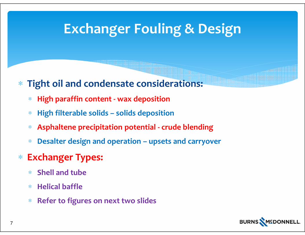
Exchanger Fouling & Design
∗ Tight oil and condensate considerations:
∗ High paraffin content - wax deposition
∗ High filterable solids – solids deposition
∗ Asphaltene precipitation potential - crude blending
∗ Desalter design and operation – upsets and carryover
∗ Exchanger Types:
∗ Shell and tube
∗ Helical baffle
∗ Refer to figures on next two slides
7
8
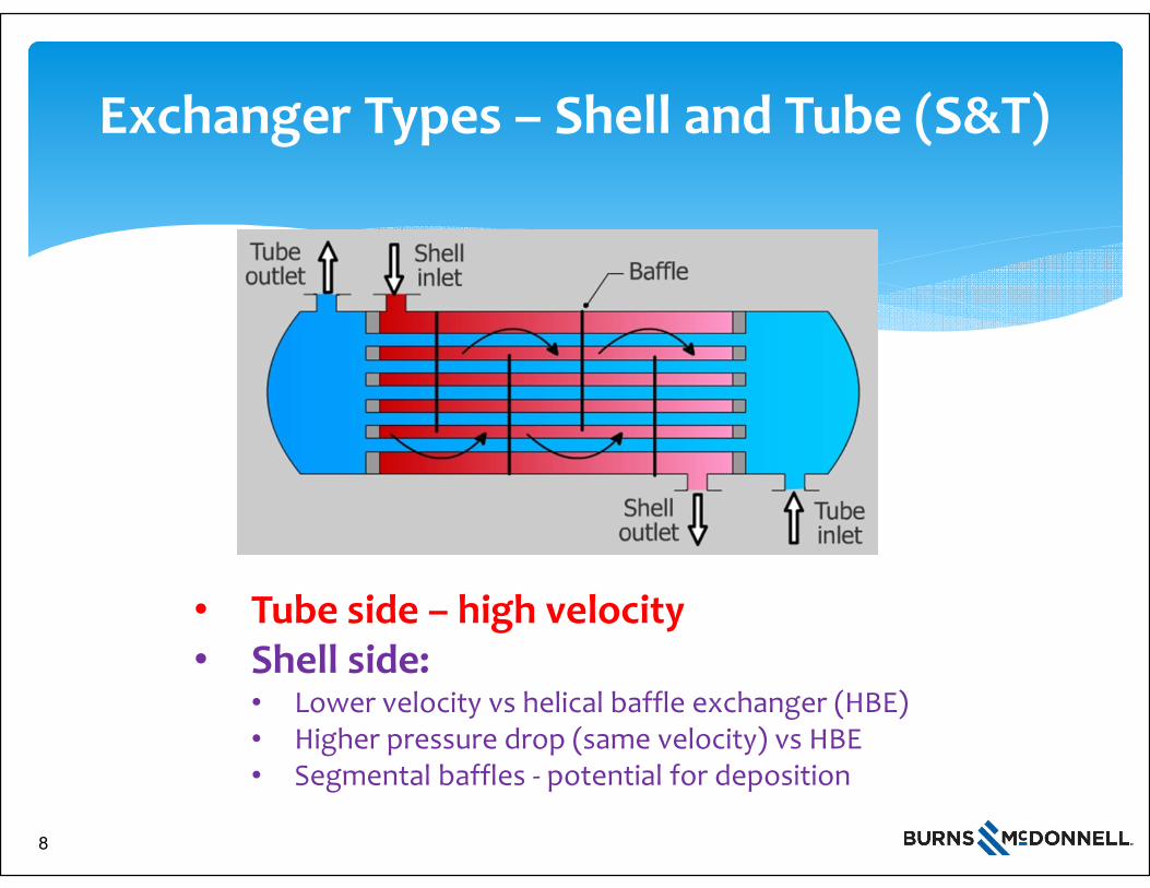
Exchanger Types – Shell and Tube (S&T)
• Tube side – high velocity• Shell side:
• Lower velocity vs helical baffle exchanger (HBE)• Higher pressure drop (same velocity) vs HBE• Segmental baffles - potential for deposition
8
9
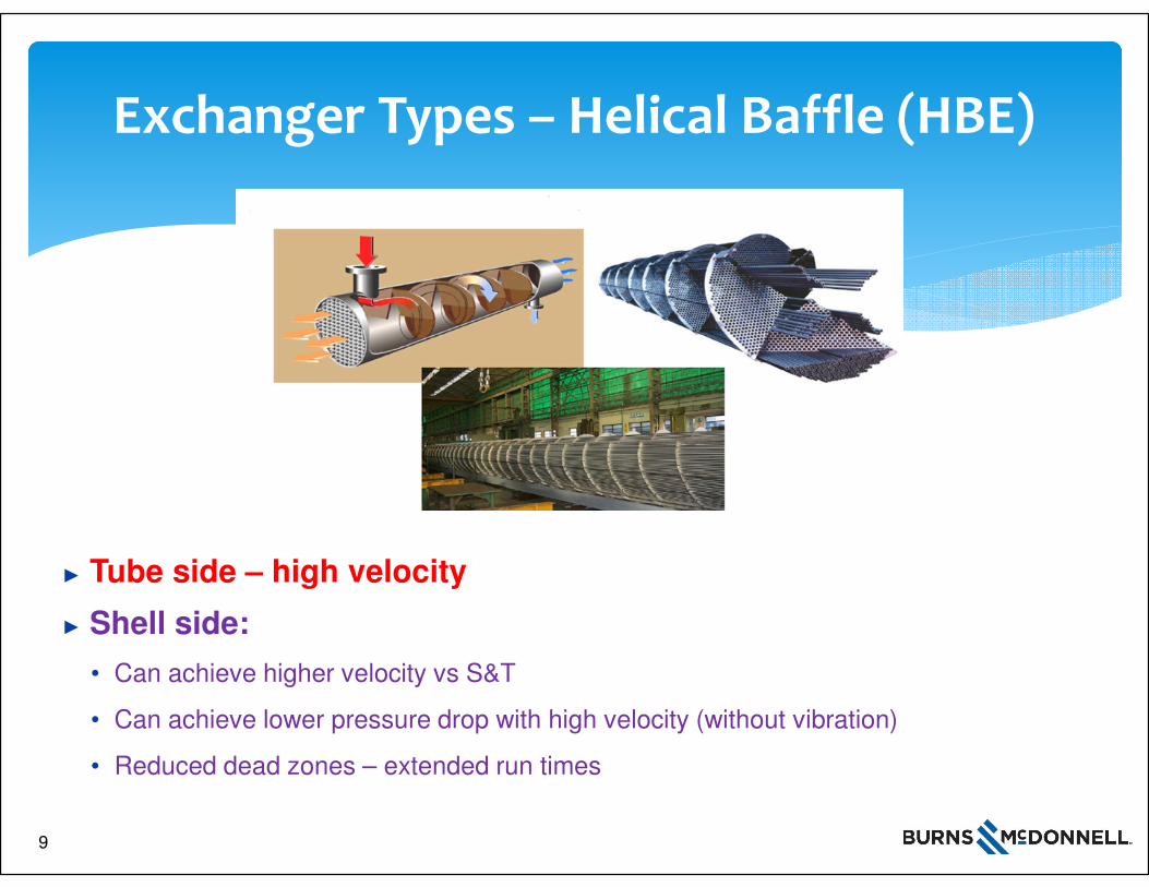
Exchanger Types – Helical Baffle (HBE)
► Tube side – high velocity
► Shell side:
• Can achieve higher velocity vs S&T
• Can achieve lower pressure drop with high velocity (without vibration)
• Reduced dead zones – extended run times
9
10
Exchanger Selection Methodology
∗ Exchanger Selection – to start:
∗ Optimization / process simulation is complete
∗ Configuration / number of heat exchangers defined
∗ Hot and cold streams, flowrates, and exchanger duties defined
∗ Methodology
∗ Assess causes of fouling in the cold, intermediate and hot train
∗ Based on causes, assess: can hot and cold fluids be placed on the shell and/or the tube side for S&T and Helical baffle exchangers (HBE)?
∗ Use exchanger modeling tool (i.e. HTRI, B-JAC) with prescribed design requirements and conduct comparison
10
11
Exchanger Selection Methodology
∗ Methodology (continued)
∗ Apply design margins, fouling factors, exchanger cleaning requirements
∗ Tabulate results for S&T and HBE’s while placing the hot and cold fluids on each of the applicable sides of the exchanger
∗ Compare area, pressure drop, on-line cleaning considerations and installed capital and/or lifecycle costs
∗ Based upon results - select exchanger type and fluid placement
∗ Other considerations – bigger picture
∗ Exchanger pressure drop
∗ Pumping horsepower
∗ Equipment design pressure
∗ Metallurgy
∗ Seek existing exchanger fouling data
11
12
Exchanger Fouling & Design – Cold PHT
∗ Causes of Fouling:
∗ Fouling is more likely to occur on cold crude side
∗ Cause: Wax build-up, high filterable solids deposition
∗ Design Considerations:
∗ Maintain high fluid velocity (>5 fps)
∗ Minimize dead spots on crude side (i.e. NOT place on shell side for S&T option)
∗ Recognize potential to reduce ∆P for crude if placed on the shell side.
∗ Other (include design margins, fouling factors, exchanger cleaning requirements)
∗ Exchanger Selections:
∗ Tabulate and compare results
∗ Continue through all cold PHT exchanger services and make selections
∗ Apply “Other considerations” for final selections12
13
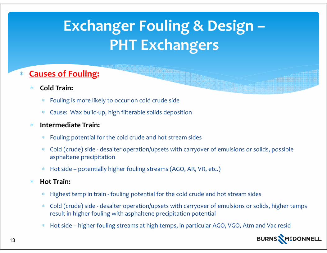
Exchanger Fouling & Design –PHT Exchangers
∗ Causes of Fouling:
∗ Cold Train:
∗ Fouling is more likely to occur on cold crude side
∗ Cause: Wax build-up, high filterable solids deposition
∗ Intermediate Train:
∗ Fouling potential for the cold crude and hot stream sides
∗ Cold (crude) side - desalter operation/upsets with carryover of emulsions or solids, possible asphaltene precipitation
∗ Hot side – potentially higher fouling streams (AGO, AR, VR, etc.)
∗ Hot Train:
∗ Highest temp in train - fouling potential for the cold crude and hot stream sides
∗ Cold (crude) side - desalter operation/upsets with carryover of emulsions or solids, higher temps result in higher fouling with asphaltene precipitation potential
∗ Hot side – higher fouling streams at high temps, in particular AGO, VGO, Atm and Vac resid
13
14
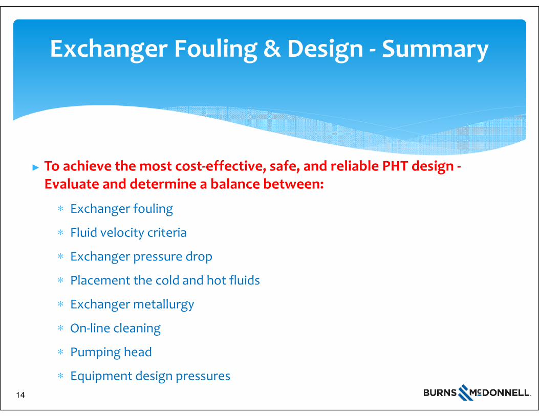
Exchanger Fouling & Design - Summary
► To achieve the most cost-effective, safe, and reliable PHT design -Evaluate and determine a balance between:
∗ Exchanger fouling
∗ Fluid velocity criteria
∗ Exchanger pressure drop
∗ Placement the cold and hot fluids
∗ Exchanger metallurgy
∗ On-line cleaning
∗ Pumping head
∗ Equipment design pressures
14
15
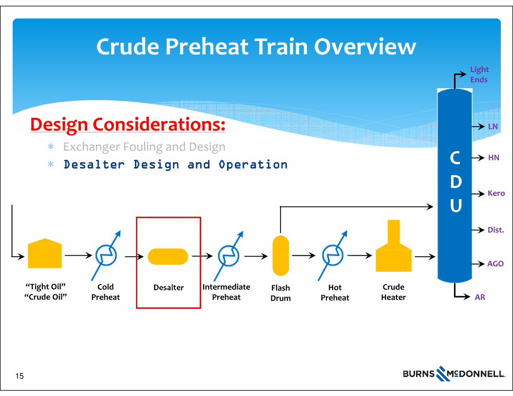
Crude Preheat Train Overview
∗ Exchanger Fouling and Design
∗ Desalter Design and OperationDesalter Design and OperationDesalter Design and OperationDesalter Design and Operation
1 5
“Tight Oil”“Crude Oil”
Cold Preheat
Hot Preheat
DesalterAR
AGO
LightEnds
LN
HN
Kero
Dist.
CDU
Crude Heater
Intermediate Preheat
Design Considerations:
Flash Drum
15
16
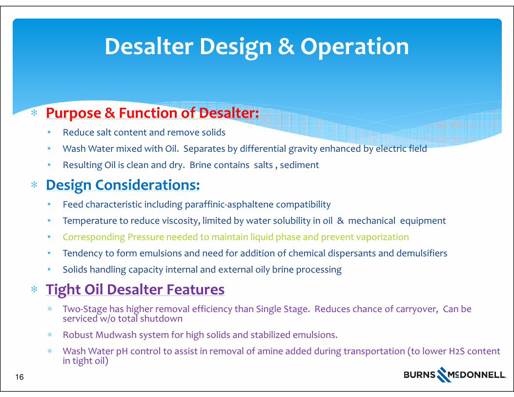
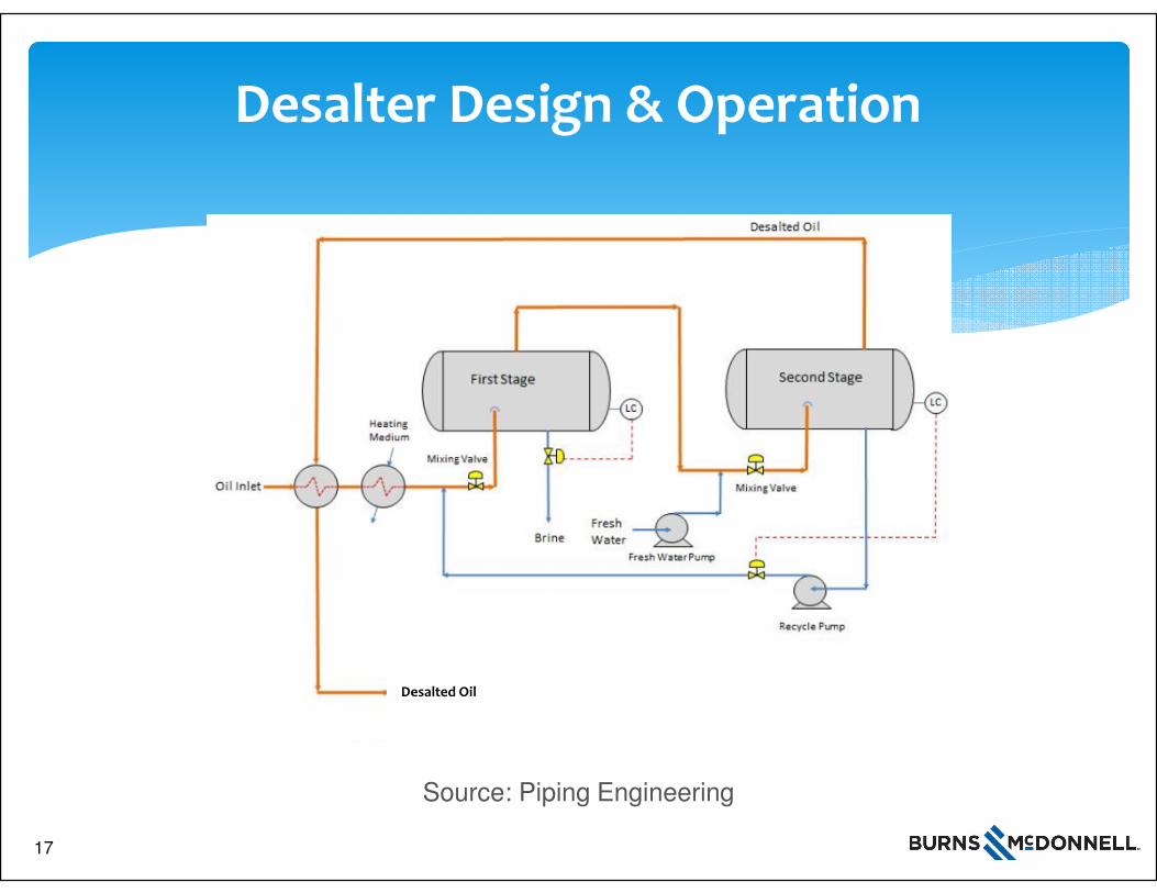
Desalter Design & Operation
∗ Purpose & Function of Desalter:• Reduce salt content and remove solids
• Wash Water mixed with Oil. Separates by differential gravity enhanced by electric field
• Resulting Oil is clean and dry. Brine contains salts , sediment
∗ Design Considerations:• Feed characteristic including paraffinic-asphaltene compatibility
• Temperature to reduce viscosity, limited by water solubility in oil & mechanical equipment
• Corresponding Pressure needed to maintain liquid phase and prevent vaporization
• Tendency to form emulsions and need for addition of chemical dispersants and demulsifiers
• Solids handling capacity internal and external oily brine processing
∗ Tight Oil Desalter Features∗ Two-Stage has higher removal efficiency than Single Stage. Reduces chance of carryover, Can be
serviced w/o total shutdown
∗ Robust Mudwash system for high solids and stabilized emulsions.
∗ Wash Water pH control to assist in removal of amine added during transportation (to lower H2S content in tight oil)
16
17
Desalter Design & Operation
Source: Piping Engineering
Desalted Oil
17
18
Crude Preheat Train Overview
∗ Exchanger Fouling and Design
∗ Desalter Design and Operation
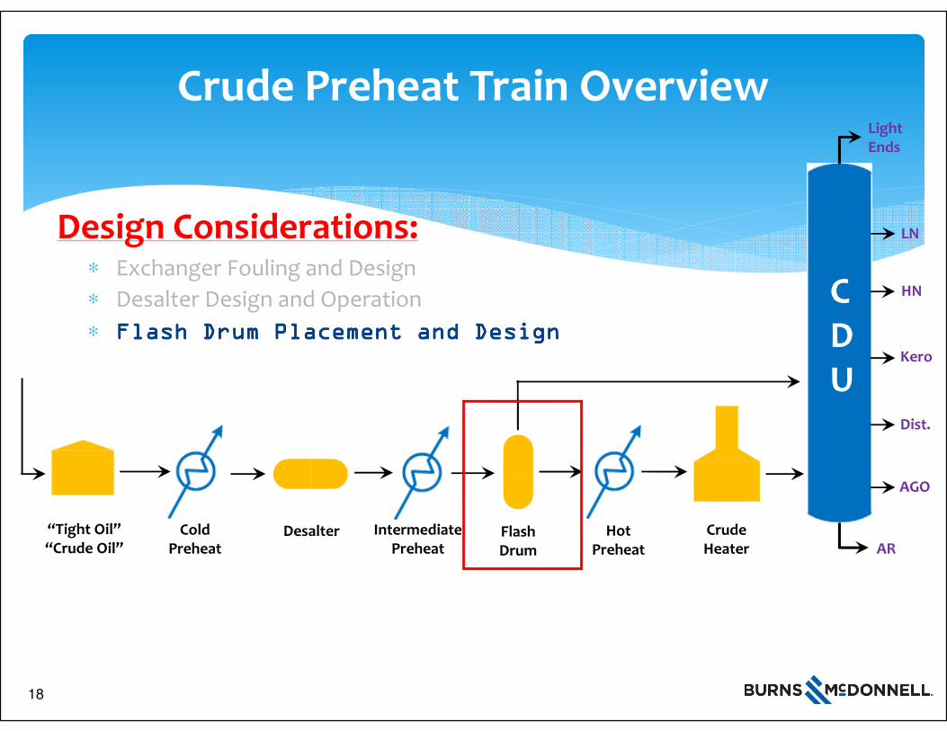
∗ Flash Drum Placement and DesignFlash Drum Placement and DesignFlash Drum Placement and DesignFlash Drum Placement and Design
1 81 8
“Tight Oil”“Crude Oil”
Cold Preheat
Hot Preheat
DesalterAR
AGO
LightEnds
LN
HN
Kero
Dist.
CDU
Crude Heater
Intermediate Preheat
Design Considerations:
Flash Drum
18
19
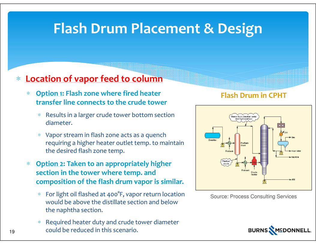
Flash Drum Placement & Design
∗ Location of vapor feed to column
∗ Option 1: Flash zone where fired heater transfer line connects to the crude tower
∗ Results in a larger crude tower bottom section diameter.
∗ Vapor stream in flash zone acts as a quench requiring a higher heater outlet temp. to maintain the desired flash zone temp.
∗ Option 2: Taken to an appropriately higher section in the tower where temp. and composition of the flash drum vapor is similar.
∗ For light oil flashed at 400°F, vapor return location would be above the distillate section and below the naphtha section.
∗ Required heater duty and crude tower diameter could be reduced in this scenario.
Source: Process Consulting Services
Flash Drum in CPHT
19
20
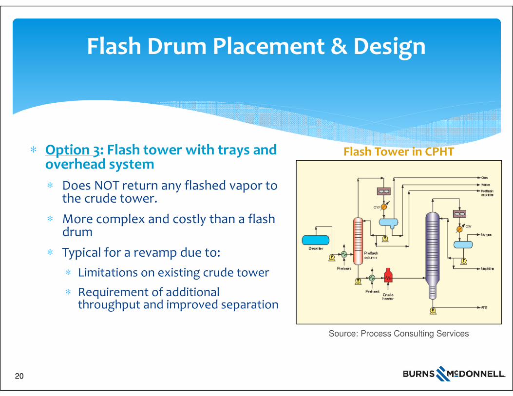
Flash Drum Placement & Design
∗ Option 3: Flash tower with trays and overhead system
∗ Does NOT return any flashed vapor to the crude tower.
∗ More complex and costly than a flash drum
∗ Typical for a revamp due to:
∗ Limitations on existing crude tower
∗ Requirement of additional throughput and improved separation
Source: Process Consulting Services
Flash Tower in CPHT
20
21
Crude Preheat Train Overview
∗ Exchanger Fouling and Design
∗ Desalter Design and Operation
∗ Flash Drum Placement and Design
∗ Charge Heater Fouling and DesignCharge Heater Fouling and DesignCharge Heater Fouling and DesignCharge Heater Fouling and Design
2 12 12 1
“Tight Oil”“Crude Oil”
Cold Preheat
Hot Preheat
DesalterAR
AGO
LightEnds
LN
HN
Kero
Dist.
CDU
Crude Heater
Intermediate Preheat
Design Considerations:
Flash Drum
21
22
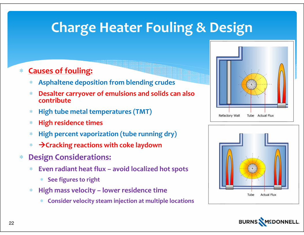
Charge Heater Fouling & Design
∗ Causes of fouling:
∗ Asphaltene deposition from blending crudes
∗ Desalter carryover of emulsions and solids can also contribute
∗ High tube metal temperatures (TMT)
∗ High residence times
∗ High percent vaporization (tube running dry)
∗ ����Cracking reactions with coke laydown
∗ Design Considerations:
∗ Even radiant heat flux – avoid localized hot spots
∗ See figures to right
∗ High mass velocity – lower residence time
∗ Consider velocity steam injection at multiple locations
22
23
Charge Heater Fouling & Design
∗ Design Considerations (cont’d):
∗ Max percent vaporization (50 – 60%)
∗ Lights content of tight oil exacerbates
∗ Can recirculate atm resid
∗ Include on-line decoking or pigging of tubes
∗ Charge Heater type:
∗ Double fired – even heat flux
∗ All floor or wall and floor burners
∗ Floor burners alone can accomplish even heat flux and is lower cost
∗ Multiple cells – for on-line cleaning
23
24
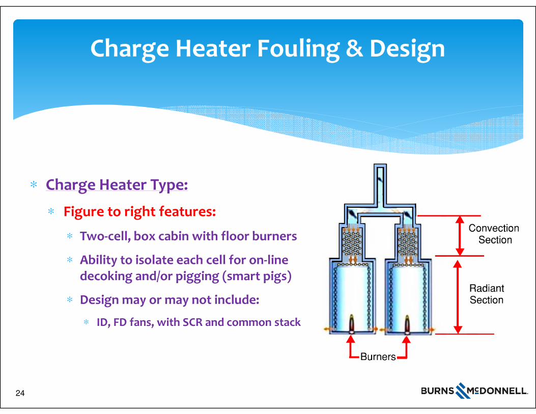
Charge Heater Fouling & Design
∗ Charge Heater Type:
∗ Figure to right features:
∗ Two-cell, box cabin with floor burners
∗ Ability to isolate each cell for on-line decoking and/or pigging (smart pigs)
∗ Design may or may not include:
∗ ID, FD fans, with SCR and common stack
24
25
Charge Heater Fouling & Design
∗ Other Design Considerations:
∗ Carefully consider charge heater design margin
∗ Allows operation at higher capacity when cleaning one cell
∗ Fouling in fired heater tubes is less desirable than fouling in heat exchanger
∗ Strive for max heater inlet temperatures
∗ Vaporization at heater outlet affected by
∗ Flash zone temperature and pressure
∗ Consider recirculation of atm resid
25
26
Conclusion
∗ Tight oils and condensates are presenting unique challenges for design of new CPHT’s and in operating a existing CPHT’s
∗ Existing crude units are experiencing high fouling in heat exchangers and charge heater tubes leading to unplanned outages and loss of production
∗ Crude unit reliability can be increased in new unit design, in crude unit retrofits and/or in adjusting operating parameters in existing units
26
27
Conclusion
∗ This paper has provided specific design approaches for the CPHT to address the unique challenges when processing tight oil and condensates, including:
∗ Exchanger fouling and design
∗ Desalter design and operation
∗ Flash drum placement and design
∗ Fired heater fouling and design
27

Questions and Answers
Burns & McDonnell – 100% Employee Owned!
Mark W. [email protected]
Dominic [email protected]
Abyar [email protected]
28
28