Embed Size (px)
Citation preview

SGT-200 SAFETY GROUND TESTER
USER’S MANUAL
Vanguard Instruments Company, Inc. 1520 S. Hellman Ave. Ontario, California 91761, USA
TEL: (909) 923-9390 FAX: (909) 923-9391
January 2017 Revision 1.0

SGT-200 USER’S MANUAL REV 1.0
i
SAFETY SUMMARY
FOLLOW EXACT OPERATING PROCEDURES Any deviation from the procedures described in this user’s manual may create one or more safety hazards, damage the SGT-200, or cause errors in the test results. Vanguard Instruments Co., Inc. assumes no liability for unsafe or improper use of the SGT-200. The following safety precautions must be observed during all phases of test setup, test hookups, testing, and test lead disconnection.
SAFETY WARNINGS AND CAUTIONS The SGT-200 shall be used only by trained operators. All circuit breakers under test shall be off-line and fully isolated.
SERVICE AND REPAIR • Do not install substitute parts or perform any unauthorized modification to any SGT-200 test unit. • Repairs must be performed only by Vanguard Instruments Company factory personnel or by an authorized
repair service provider. Unauthorized modifications can cause safety hazards and will void the manufacturer’s warranty.
EQUIPMENT RATINGS IP Rating: The enclosure for the SGT-200 has an IP rating of 32.
Pollution Degree: The SGT-200 has a pollution rating of 2.
Operating Voltage: The SGT-200 is rated for use with an operating voltage of 120V or 240V, auto-ranging ±10% of selected voltage.
Power Cord: The SGT-200 is supplied with a 16 AWG, 16A power cord with a NEMA 5-15P plug. Replacement cable shall have the same or better rating and is available through the manufacturer.
VENTILATION REQUIREMENTS The SGT-200 must be operated with the enclosure lid open.
SAFETY SYMBOLS Indicates that caution should be exercised
Indicates location of chassis ground terminal
CLEANING To clean the SGT-200:
• Disconnect all cables and turn the unit off. • Use a soft, lint-free cloth to wipe all surfaces clean. • Avoid getting moisture in openings and connectors. • Don't use any cleaning products or compressed air.

REV 1.0 SGT-200 USER’S MANUAL
ii
TABLE OF CONTENTS CONVENTIONS USED IN THIS DOCUMENT ..................................................................................... 1 1.0 INTRODUCTION .................................................................................................................... 2
1.1 General Description and Features ................................................................................... 2 1.2 SGT-200 Technical Specifications .................................................................................... 4 1.3 SGT-200 Controls and Indicators ..................................................................................... 5
2.0 PRE-TEST SETUP ................................................................................................................... 6 2.1 Operating Voltages .......................................................................................................... 6 2.2 LCD Screen Contrast Control ............................................................................................ 6
3.0 OPERATING PROCEDURES ................................................................................................... 7 3.1 Lid Removal ...................................................................................................................... 7 3.2 Cable Connection Post and Sense Wire Installation ........................................................ 9 3.4 Setting the Interface Language ...................................................................................... 12 3.5 Setting the Option to Print the Calibration Expiration Date .......................................... 13 3.6 Setting the Units of Measure ......................................................................................... 15 3.7 Testing Procedures ........................................................................................................ 17
3.7.1. Entering Test Record Header Information ............................................................. 17 3.7.2. Performing a Test ................................................................................................... 20
3.8 Working With Test Records ........................................................................................... 26 3.8.1. Viewing the Contents of the Working Memory ..................................................... 26 3.8.2. Saving Test Results to a Test Record ...................................................................... 28 3.8.3. Restoring a Test Record From Flash EEPROM ........................................................ 30 3.8.4. Restoring a Test Record From a USB Flash Drive ................................................... 34 3.8.5. Copying Test Records to a USB Flash Drive ............................................................ 36 3.8.6. Printing the Test Record Directory ......................................................................... 39 3.8.7. Erasing Test Records from the Unit's Flash EEPROM ............................................. 42 3.8.8. Erasing Test Records from a USB Flash Drive ......................................................... 47
4.0 Getting the Latest Firmware, Software, and Manuals....................................................... 50
LIST OF FIGURES Figure 1. SGT-200 Controls and Indicators ..................................................................................... 5 Figure 2. Sample Test Report Printout with Calibration Expiration Date ..................................... 14 Figure 3. Sample SGT-200 Test Results Printout .......................................................................... 25 Figure 4. Sample Thumb Drive Directory Printout ....................................................................... 41 Figure 5. Sample Internal Test Record Directory Printout............................................................ 41

REV 1.0
1
This docu
• A key
• Menu
• SGT-2
• When(optio
• Warn
WA
• Impo
N
1. 2. 3. 4. 5.
1. 2. 3. 4. 5.
SGT-200 U
C
ument uses
y, switch, or
u names are
200 screen o
n instructionon 3 should
ning message
ARNING
Wa
ortant notes
OTE
No
OPTION 1
OPTION 2
OPTION 3
OPTION 4
OPTION 5
OPTION 1
OPTION 2
OPTION 3
OPTION 4
OPTION 5
USER’S MAN
CONVENT
the followin
knob on the
e referenced
output is sho
ns are providbe selected
es are indica
arning mess
are indicate
te details
2
3
4
5
2
3
4
5
UAL
TIONS US
ng conventio
e SGT-200 is
as “MENU N
own as:
ded, the men):
ated as:
sage
ed as:
SED IN TH
ons:
indicated as
NAME”
nu item that
HIS DOCU
s [KEY], [S
t should be s
UMENT
SWITCH], [
selected is sh
[KNOB].
hown in bold

SGT-200 USER’S MANUAL REV 1.0
2
1.0 INTRODUCTION 1.1 General Description and Features The Vanguard SGT-200 Safety Ground Tester is a 200A DC micro-ohmmeter designed specifically to measure the resistance of protective in-service grounding and jumper cable assemblies. The SGT-200 can measure the resistance of the grounding cables, clamps and ferrules. The measured resistance values can be compared against the calculated values (using the ASTM 2249-03 standard) and a Pass/Fail result can be printed along with the measured resistance values.
The SGT-200 can measure resistance value from 1 micro-ohm to 1000 milliohms. A typical test requires the two ends of the safety ground cable to be connected to the terminals of the SGT-200. The resistance of the cable and ferrules can then be measured. If the cable size, cable length and temperature are provided, the SGT-200 will determine if the cables passes or fails the test and a pass/fail indicator will be printed on the test report.
Test results are printed on the unit's built-in 2.5” thermal printer. A 44-key QWERTY-style rugged membrane keypad is used to input information and control the SGT-200. A back-lit graphic LCD screen (128 x 64 pixels) is used to display menus and test results.
The SGT-200 can store up to 100 test records in its internal memory. It also features a USB Flash drive interface port that can be used to store test data in a USB flash drive (not included). The SGT-200 also features an RS-232C port that is used for factory diagnostics and calibration.
Test records can be reviewed and printed on a PC using the provided Vanguard VUS software.
In-Service Cable Testing The SGT-200 measures the total resistance value of the cable under test and then compares it to the calculated value to determine the Pass or Fail result. In order to calculate the total resistance value, the user is first prompted for the cable size, cable length, and cable temperature. Total resistance (Rm) is calculated in accordance with the ASTM F2249-03 standard using the formula below:
Rm = 1.05 RL + 2Y = 1.05 RL + 320 µΩ*
Where:
Y = Resistance of clamps, ferrule, and portions of the cable inside the ferrule, in milliohms* L = Cable length in feet (ferrule to ferrule measurement to the nearest inch) R = Cable resistance, in milliohms/foot * NOTE: The clamp and ferrule resistance value of 160 µΩ is used per the ASTM-F2249-03 standard.
REV 1.0 SGT-200 USER’S MANUAL
3
The SGT-200 will calculate the maximum resistance value of the cable under test, measure the resistance value and compare this value against the limit. The resistance value and a PASS or FAIL result can be printed on the thermal printer.
Test Cable Sizes and Length Typical Safety Ground Cable sizes are #2, 1/0, 2/0, and 4/0. The test cable length, ranging from 1' to 50' per table 2 in the F2249-03 standard, is entered by the user. Cable size and length can be entered in either English or Metric units.
Test Record Storage The SGT-200 can store 100 test records internally. Each test record contains test header information, test cable size, test cable length, temperature, test current, and cable resistance. Test records can also be stored on a USB flash drive via the unit's USB flash drive interface.
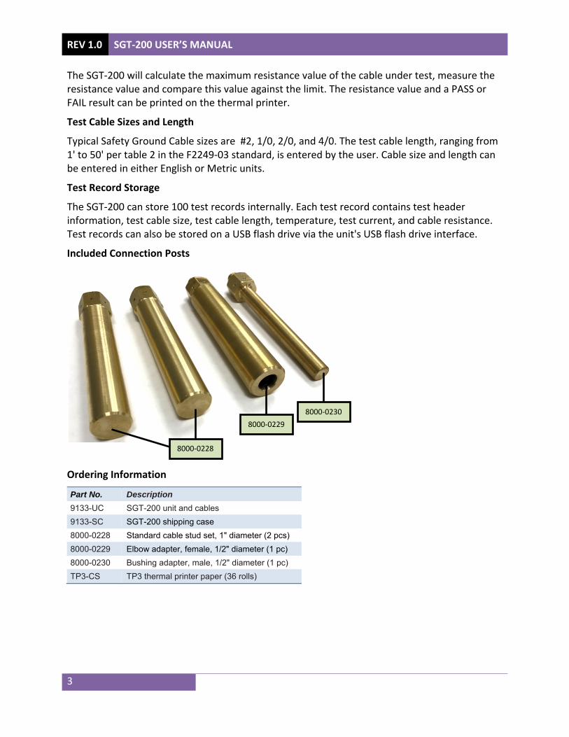
Included Connection Posts
Ordering Information Part No. Description 9133-UC SGT-200 unit and cables 9133-SC SGT-200 shipping case 8000-0228 Standard cable stud set, 1" diameter (2 pcs) 8000-0229 Elbow adapter, female, 1/2" diameter (1 pc) 8000-0230 Bushing adapter, male, 1/2" diameter (1 pc) TP3-CS TP3 thermal printer paper (36 rolls)
8000-0228
8000-0229 8000-0230
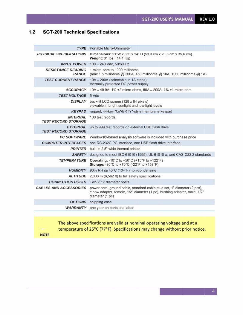
1.2 S
PHYS
T
TE
TE
CO
CABL
NO
SGT-200 Te
SICAL SPECIF
INPURESISTANCE
TEST CURREN
ATEST
EST RECORD E
EST RECORD PC S
OMPUTER INT
TEMP
CONNECTIOLES AND ACCE
W
TE
The atemp
echnical Sp
TYPE PFICATIONS D
WUT POWER 1E READING
RANGE 1(
NT RANGE 1t
CCURACY 1T VOLTAGE 5
DISPLAY bv
KEYPAD rINTERNAL STORAGE
1
EXTERNAL STORAGE
u
OFTWARE WTERFACES o
PRINTER bSAFETY d
PERATURE OS
HUMIDITY 9ALTITUDE 2ON POSTS TESSORIES p
ed
OPTIONS sWARRANTY o
above specifperature of 2
pecificatio
Portable Micro-Dimensions: 2Weight: 31 lbs100 240 Vac,1 micro-ohm tomax 1.5 millioh
10A 200A (sehermally protec
10A 49.9A: 1%5 Vdc back-lit LCD scviewable in brigrugged, 44-key100 test record
up to 999 test r
Windows®-basone RS-232C Pbuilt-in 2.5” widdesigned to meOperating: -10Storage: -30°C90% RH @ 40°2,000 m (6,562Two 2”/3” diampower cord, groelbow adapter, diameter (1 pc)shipping case one year on pa
ications are 25°C (77°F).
ns
-Ohmmeter 21”W x 8”H x 14. (14.1 Kg) 50/60 Hz 1000 milliohmhms @ 200A, 4electable in 1A cted DC power% ±2 micro-oh
creen (128 x 64ght sunlight and "QWERTY"-sts
records on exte
sed analysis soPC interface, one thermal print
eet IEC 61010 (0°C to +50°C (+C to +70°C (-22°C (104°F) non2 ft) to full safeteter posts ound cable, stafemale, 1/2" d
)
rts and labor
valid at nomSpecification
SGT-200
4” D (53.3 cm x
ms 450 milliohms @steps); r supply ms, 50A 200
4 pixels) d low-light levetyle membrane
ernal USB flash
oftware is includne USB flash dter (1995), UL 610+15°F to +122°2°F to +158°F) n-condensing y specifications
andard cable stiameter (1 pc),
minal operatns may chan
USER’S MA
x 20.3 cm x 35
@ 10A, 1000 m
A: 1% ±1 micro
els e keypad
h drive
ded with purchadrive interface
010-a, and CAS°F)
s
tud set, 1" diam bushing adapt
ting voltage ange without
NUAL RE
5.6 cm)
milliohms @ 1A
o-ohm
ase price
S-C22.2 standa
meter (2 pcs), ter, male, 1/2"
and at a prior notice
V 1.0
4
A)
ards
.
REV 1.0 SGT-200 USER’S MANUAL
5
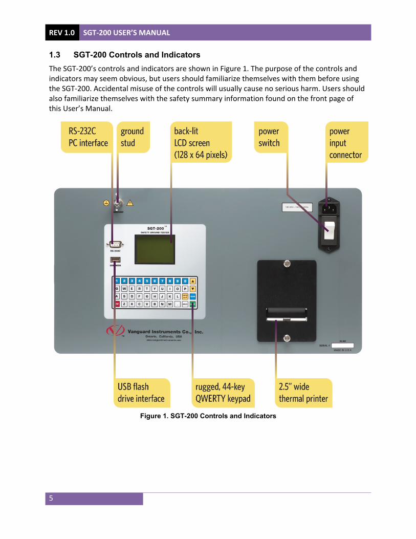
1.3 SGT-200 Controls and Indicators The SGT-200’s controls and indicators are shown in Figure 1. The purpose of the controls and indicators may seem obvious, but users should familiarize themselves with them before using the SGT-200. Accidental misuse of the controls will usually cause no serious harm. Users should also familiarize themselves with the safety summary information found on the front page of this User’s Manual.
Figure 1. SGT-200 Controls and Indicators

SGT-200 USER’S MANUAL REV 1.0
6
2.0 PRE-TEST SETUP 2.1 Operating Voltages The SGT-200 operate on voltages between 120-240 Vac, 50/60 Hz.
2.2 LCD Screen Contrast Control To increase the LCD screen contrast, press and hold the [] key for two seconds. Release the button when the desired contrast level has been reached.
To decrease the LCD screen contrast, press and hold the [] key for two seconds. Release the button when the desired contrast level has been reached.
2.3 Safety Ground Always ground the SGT-200 to the substation ground before connecting cables to the unit.
2.4 Printer Paper The SGT-200’s built-in thermal printer uses 2.5" wide thermal paper for printing test results. To maintain the highest print quality and to avoid paper jams, the use of thermal paper supplied by Vanguard Instruments Company is highly recommended. Additional paper can be ordered from the following sources:
Vanguard Instruments Co, Inc. 1520 S. Hellman Avenue Ontario, CA 91761 Tel: 909-923-9390 Fax: 909-923-9391 Part Number: TP3-CS BG Instrument Co. 13607 E. Trent Avenue Spokane, WA 99216 Tel: 509-893-9881 Fax: 509-893-9803 Part Number: VIC TP-3 paper

REV 1.0 SGT-200 USER’S MANUAL
7
3.0 OPERATING PROCEDURESLid Removal The SGT-200 features a lid that can be easily removed for greater convenience during testing. Follow the steps below to remove the lid:
a. Remove the set screw from the back of the left lid hinge.
b. Rotate the lid open approximately 45 degrees to align the enclosure tab with the groove
in the lid hinge.
LID OPEN AT 90° (Tab NOT aligned with groove) tab
groove
LID OPEN AT 45° (Tab aligned with groove) tab groove
remove screw

SGT-200 USER’S MANUAL REV 1.0
8
c. Slide the lid horizontally to the right.
d. Continue to slide the lid horizontally to the right to completely remove.

REV 1.0
9
3.1 CFollow th
a. Sep
SGT-200 U
Cable Connhe steps belo
elect the cabosts into the
NOTE
Makpost
USER’S MAN
nection Poow to install
ble connectie SGT-200 fe
ke sure the pts will yield i
UAL
st and Sen the cable co
on posts to emale recept
posts are scrinaccurate te
inst
nse Wire Inonnection p
be used wittacles on ea
rewed in comest results.
fem
alled cable conn
nstallation osts and sen
h the test cach side of th
mpletely and
male receptacle
nection post
nse wires:
ables. Screwhe SGT-200.
d firmly. Loo
w the connec
se connectio
tion
on

b. Csh
c. C
d. C
onnect the shown below
onnect the S
onnect the g
NOTE
The
sense wires w:
SGT-200 gro
ground cable
e cable does
to the cable
ound and pow
e to be teste
s NOT need t
e connection
wer cables.
ed to the cab
to be un-wo
SGT-200
n posts on bo
ble connecti
und and can
sen
ground
USER’S MA
oth sides of t
on posts as
n remain coi
nse wire
cable to be test
NUAL RE
the SGT-200
shown below
led.
ted
V 1.0
10
0 as
w:

REV 1.0 SGT-200 USER’S MANUAL
11
3.2 Setting the Date and Time To set the date and time:
a. Start from the “START-UP” menu:
Press the [3] key (SETUP).
b. The following screen will be displayed:
Press the [4] key (SET TIME)
c. The following screen will be displayed:
Type in the date using the keypad. The following screen will be displayed:
Enter the time using the keypad. When the time has been entered, you will be immediately returned to the “START-UP” menu.
ENTER TIME
HH:MM:SS
ENTER DATE
MM-DD-YY
1. RECORD ID 2. REVIEW RECORD 3. SAVE/RESTORE RECORD 4. set time 5. set language 6. CAL NOTICE ON/OFF 7. SET UNITS
1.CERT TEST
2.QUICK TST
3.SETUP time: 10:11:12 23°C
date: 12/29/16 73°F

SGT-200 USER’S MANUAL REV 1.0
12
3.3 Setting the Interface Language Follow the steps below to set the interface language (English):
a. Start from the “START-UP” menu:
Press the [3] key (SETUP).
b. The following screen will be displayed:
Press the [5] key (SET LANGUAGE).
c. The following screen will be displayed:
Select the preferred interface language by pressing the corresponding key on the keypad ([1], [2], or [3]). The interface language will be set and a confirmation screen will be displayed as shown below:
Press any key to return to the “START-UP” menu.
ENGLISH SET
1. ENGLISH 2. TURKISH 3. SPANISH
1. RECORD ID 2. REVIEW RECORD 3. SAVE/RESTORE RECORD 4. set time 5. set language 6. CAL NOTICE ON/OFF 7. SET UNITS
1.CERT TEST
2.QUICK TST
3.SETUP time: 10:11:12 23°C
date: 12/29/16 73°F
REV 1.0 SGT-200 USER’S MANUAL
13
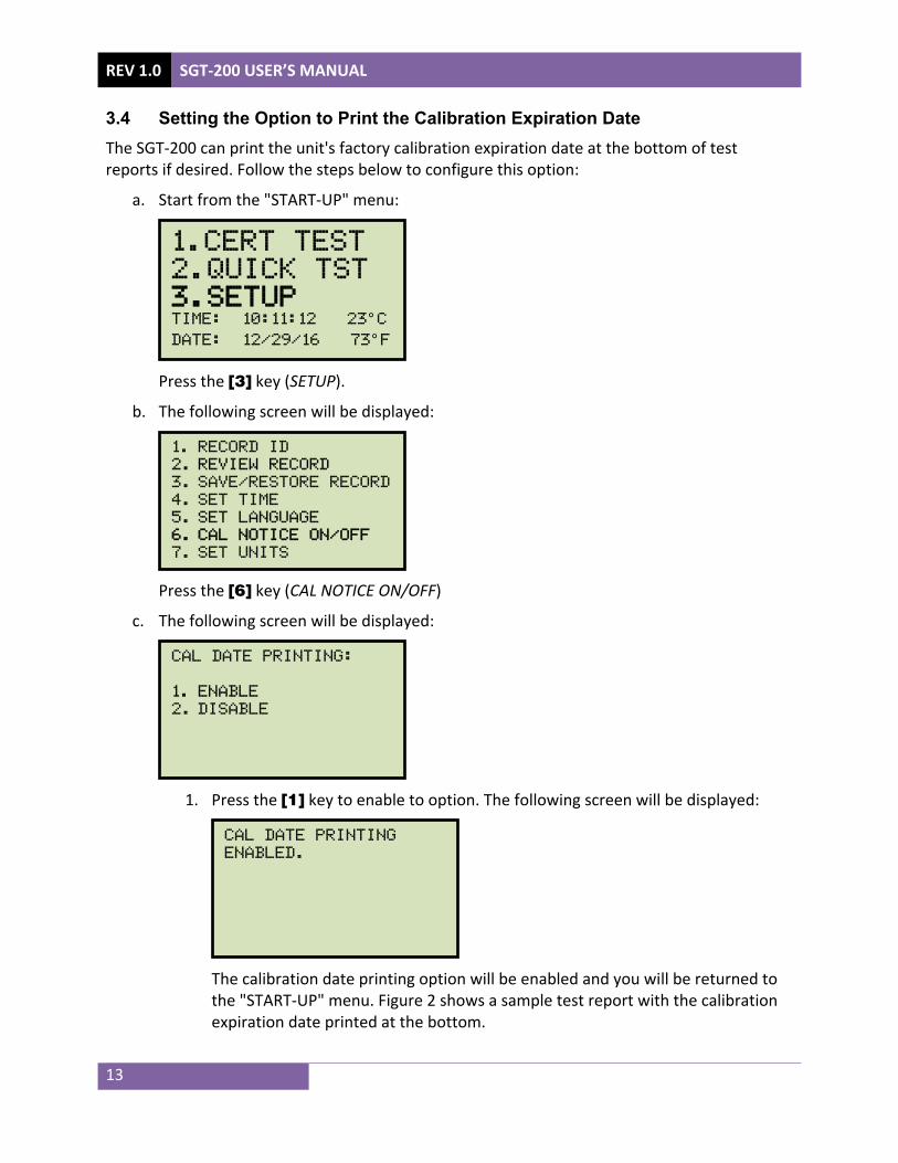
3.4 Setting the Option to Print the Calibration Expiration Date The SGT-200 can print the unit's factory calibration expiration date at the bottom of test reports if desired. Follow the steps below to configure this option:
a. Start from the "START-UP" menu:
Press the [3] key (SETUP).
b. The following screen will be displayed:
Press the [6] key (CAL NOTICE ON/OFF)
c. The following screen will be displayed:
1. Press the [1] key to enable to option. The following screen will be displayed:
The calibration date printing option will be enabled and you will be returned to the "START-UP" menu. Figure 2 shows a sample test report with the calibration expiration date printed at the bottom.
CAL DATE PRINTING
ENABLED.
CAL DATE PRINTING:
1. ENABLE 2. DISABLE
1. RECORD ID 2. REVIEW RECORD 3. SAVE/RESTORE RECORD 4. set time 5. set language 6. CAL NOTICE ON/OFF 7. SET UNITS
1.CERT TEST
2.QUICK TST
3.SETUP time: 10:11:12 23°C
date: 12/29/16 73°F

SGT-200 USER’S MANUAL REV 1.0
14
2. Press the [2] key to disable the option. The following screen will be displayed:
Press any key to return to the "START-UP" menu.
Figure 2. Sample Test Report Printout with Calibration Expiration Date
CAL DATE PRINTING
DISABLED.
REV 1.0
15
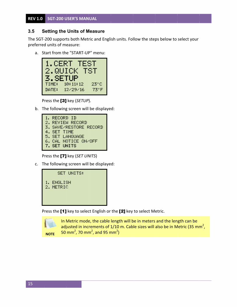
3.5 SThe SGT-preferred
a. St
P
b. T
P
c. T
P
SGT-200 U
Setting the -200 supportd units of me
tart from th
ress the [3]
he following
ress the [7]
he following
ress the [1]
NOTE
In Madj50
SET
1. ENGLIS2. METRIC
1. RECORD2. REVIEW3. SAVE/R4. set ti5. set la6. CAL NO7. SET UN
1.CER
2.QUI
3.SETtime: 10
date: 12
USER’S MAN
Units of Mts both Meteasure:
e "START-UP
key (SETUP
g screen will
key (SET UN
g screen will
key to selec
Metric modejusted in incmm2, 70 mm
UNITS:
SH
C
D ID
W RECORD
RESTORE R
ime
anguage
OTICE ON/
NITS
RT TES
ICK TS
TUP 0:11:12
2/29/16
UAL
Measure ric and Engli
P" menu:
).
be displaye
NITS)
be displaye
ct English or
e, the cable rements of 1m2, and 95 m
RECORD
/OFF
ST
ST
23°C
73°F
ish units. Fo
d:
d:
the [2] key
length will b1/10 m. Cab
mm2)
llow the step
to select M
be in metersble sizes will
ps below to
etric.
and the lenalso be in M
select your
gth can be Metric (35 mmm2,

SGT-200 USER’S MANUAL REV 1.0
16
d. The following screen will be displayed (English units shown for this example):
Press any key to return to the "START-UP" menu.
ENGLISH MODE SET!
REV 1.0 SGT-200 USER’S MANUAL
17
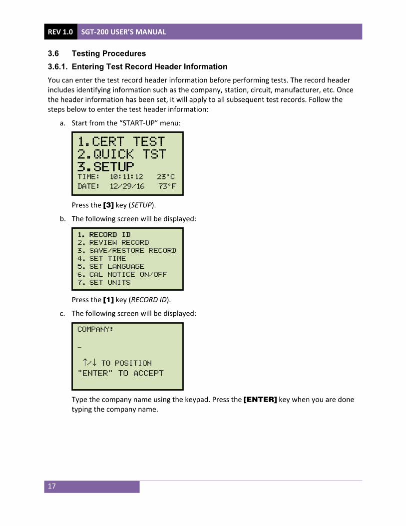
3.6 Testing Procedures 3.6.1. Entering Test Record Header Information You can enter the test record header information before performing tests. The record header includes identifying information such as the company, station, circuit, manufacturer, etc. Once the header information has been set, it will apply to all subsequent test records. Follow the steps below to enter the test header information:
a. Start from the “START-UP” menu:
Press the [3] key (SETUP).
b. The following screen will be displayed:
Press the [1] key (RECORD ID).
c. The following screen will be displayed:
Type the company name using the keypad. Press the [ENTER] key when you are done typing the company name.
COMPANY:
_
↑/↓ TO POSITION "ENTER" TO ACCEPT
1. RECORD ID 2. REVIEW RECORD 3. SAVE/RESTORE RECORD 4. set time 5. set language 6. CAL NOTICE ON/OFF 7. SET UNITS
1.CERT TEST
2.QUICK TST
3.SETUP time: 10:11:12 23°C
date: 12/29/16 73°F

SGT-200 USER’S MANUAL REV 1.0
18
d. The following screen will be displayed:
Type the location name using the keypad and then press the [ENTER] key.
e. The following screen will be displayed:
Type the manufacturer name using the keypad and then press the [ENTER] key.
f. The following screen will be displayed:
Type the safety ground cable's model information using the keypad and then press the [ENTER] key.
g. The following screen will be displayed:
Type the safety ground cable's serial number using the keypad and then press the [ENTER] key.
h. The following screen will be displayed:
SERIAL NUMBER:
_
↑/↓ TO POSITION "ENTER" TO ACCEPT
MODEL:
_
↑/↓ TO POSITION "ENTER" TO ACCEPT
MANUFACTURER:
_
↑/↓ TO POSITION "ENTER" TO ACCEPT
LOCATION:
_
↑/↓ TO POSITION "ENTER" TO ACCEPT

REV 1.0 SGT-200 USER’S MANUAL
19
Type the safety ground cable's rating using the keypad and then press the [ENTER] key.
i. The following screen will be displayed:
Type the operator’s name using the keypad and then press the [ENTER] key.
j. The following screen will be displayed:
Type any additional notes regarding the test and then press the [ENTER] key. All header information will be saved, and you will be returned to the “START-UP” menu.
NOTE:
_
↑/↓ TO POSITION "ENTER" TO ACCEPT
OPERATOR:
_
↑/↓ TO POSITION "ENTER" TO ACCEPT
RATING:
_
↑/↓ TO POSITION "ENTER" TO ACCEPT

SGT-200 USER’S MANUAL REV 1.0
20
3.6.2. Performing a Test There are two ways to perform a test using the SGT-200. You can perform a certification test or a quick test. When performing a certification test, after the test is finished, you will be given the option to print the test results and will also be able to save the test record. You can then choose to re-run the test.
When performing a quick test, after the test is finished, you will only be able to re-run the test. You will not be able to print or save the test results. The quick test is ideal for testing a batch of similar cables.
In both test modes, the user is required to enter the cable size, length, and temperature. The SGT-200 will calculate the maximum allowable resistance value according to the ASTM F2249-03 standard. The measured resistance value is then compared to the calculated value to determine whether the cable passes or fails. A "P" or "F" is displayed in the test results to indicate "Pass" or "Fail", respectively.
Follow the steps below to perform a test.
a. Start from the "START-UP" menu:
Press the [1] key (CERT TEST) to perform a certification test or press the [2] key (QUICK TST) to perform a quick test.
b. The following screen will be displayed showing the test parameters from the last test performed:
If the test parameters are correct, you can press the [START] key to start the test immediately. For this example, we will change the parameters by pressing the [CLEAR] key.
c. The following screen will be displayed:
CURRENT: 100 AMPS
GAUGE: AWG 2/0
LENGTH: 34.75 Ft
TEMP: 27.0°C
"CLEAR" TO MODIFY
"START" TO RUN TEST
1.CERT TEST
2.QUICK TST
3.SETUP time: 10:11:12 23°C
date: 12/29/16 73°F

REV 1.0 SGT-200 USER’S MANUAL
21
Select the test current by pressing the corresponding key on the keypad. We will press the [4] key (100A) for this example. You can also enter a specific test current between 10A and 200A by pressing the [6] key (CUSTOM).
d. One of the following screens will be displayed depending on the units of measure setting:
English Units Screen Metric Units Screen
Select the cable gauge by pressing the corresponding key on the keypad.
e. One of the following screens will be displayed depending on the units of measure setting:
English Units Screen Metric Units Screen
You can adjust the cable length by 3" (when using English units) or 0.1m (when using Metric units) increments. Press the [] key to increase the cable length or the [] key to decrease the cable length. The screen will be updated showing the new length. Press the [ENTER] key when the correct length is displayed.
CABLE LENGTH:
10.00 M
↑/↓ TO adjust length "ENTER" TO ACCEPT
CABLE LENGTH:
34.75 Ft
(33'0")
↑/↓ TO adjust length "ENTER" TO ACCEPT
CABLE GAUGE
1. 35mm2
2. 50mm2
3. 70mm2
4. 95mm2
CABLE GAUGE
1. AWG 2
2. AWG 1/0
3. AWG 2/0
4. AWG 4/0
SELECT TEST CURRENT
1. 10A
2. 25A
3. 50A
4. 100A
5. 200A
6. CUSTOM

SGT-200 USER’S MANUAL REV 1.0
22
f. The following screen will be displayed:
You can adjust the cable temperature by 0.5°C increments. Press the [] key to increase the cable temperature or the [] key to decrease the cable temperature. Press the [ENTER] key when the correct cable temperature is displayed.
g. A summary of the test parameters will be displayed as shown below:
Press the [START] key to run the test.
h. Once the test current has been reached, the SGT-200 will measure the resistance and update the screen as shown below:
The unit will then ramp down the current to zero and display the final test results as shown below:
TEST RESULTS
3.030 mΩ [P]100.00A
MEASURING
3.030 mΩ 100.00A TEST IN PROGRESS...
TEST PARAMETERS
CURRENT: 100 AMPS
GAUGE: AWG 2/0
LENGTH: 33.75 Ft
TEMP: 27.0°C
"START" TO RUN TEST
CABLE TEMP:
27.0°C 80.6°F
↑/↓ TO adjust length "ENTER" TO ACCEPT
REV 1.0
23
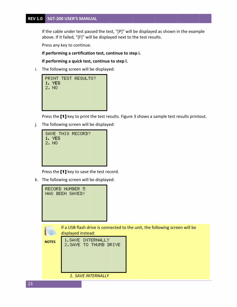
Ifa
P
IfIf
i. T
P
j. T
P
k. T
SGT-200 U
f the cable ubove. If it fa
ress any key
f performingf performinghe following
ress the [1]
he following
ress the [1]
he following
NOTES
If adis1
2
RECORD N
HAS BEEN
SAVE THI
1. YES 2. NO
PRINT TE
1. YES 2. NO
USER’S MAN
nder test pailed, "[F]" w
y to continue
g a certificatg a quick tesg screen will
key to print
g screen will
key to save
g screen will
a USB flash dplayed inste
1. SAVE IN
.SAVE INT
2.SAVE TO
UMBER 5
SAVED!
S RECORD?
ST RESULT
UAL
assed the teswill be display
e.
tion test, const, continue
be displaye
t the test res
be displaye
the test rec
be displaye
drive is conneead:
NTERNALLY
TERNALLY
THUMB DR
?
TS?
st, "[P]" will yed next to t
ntinue to steto step l. d:
sults. Figure
d:
cord.
d:
ected to the
RIVE
be displayedthe test resu
ep i.
3 shows a s
e unit, the fo
d as shown iults.
ample test r
ollowing scre
n the examp
results printo
een will be
ple
out.

SGT-200 USER’S MANUAL REV 1.0
24
Press the [1] key (SAVE INTERNALLY) to save the test record to the unit’s Flash EEPROM. The following screen will be displayed:
2. SAVE TO THUMB DRIVE
Press the [2] key (SAVE TO THUMB DRIVE) to save the test record to the connected USB Flash drive. The following screen will be displayed:
Press any key to continue.
l. The following screen will be displayed:
Press the [1] (YES) key if you would like to repeat the test. You will be returned to step b.
Press the [2] key (NO) if you do not want to repeat the test. You will be returned to the "START-UP" menu.
REPEAT TEST?
1.YES
2.NO
REC_000 SAVED TO
THUMB DRIVE.
record number 5
has been saved!

REV 1.0 SGT-200 USER’S MANUAL
25
Figure 3. Sample SGT-200 Test Results Printout

SGT-200 USER’S MANUAL REV 1.0
26
3.7 Working With Test Records 3.7.1. Viewing the Contents of the Working Memory Whenever a test is performed and the reading is kept, the data is temporarily stored in the SGT-200’s working memory. You can view the test reading in the unit’s working memory using the steps below:
a. Start from the “START-UP” menu:
Press the [3] key (SETUP).
b. The following screen will be displayed:
Press the [2] key (REVIEW RECORD).
c. The following screen will be displayed:
1. PRINT TO LCD
Press the [1] key (PRINT TO LCD) to display the test results on the unit’s LCD screen. The test record's header information will be displayed as shown below:
PRINT RECORD
1. PRINT TO LCD
2. PRINT TO PRINTER
1. RECORD ID 2. REVIEW RECORD 3. SAVE/RESTORE RECORD 4. set time 5. set language 6. CAL NOTICE ON/OFF 7. SET UNITS
1.CERT TEST
2.QUICK TST
3.SETUP time: 10:11:12 23°C
date: 12/29/16 73°F

REV 1.0 SGT-200 USER’S MANUAL
27
Press any key to continue. The test record details will be displayed as shown below:
Press any key to return to the "START-UP" menu.
2. PRINT TO PRINTER
Press the [2] key (PRINT TO PRINTER) to print the test results on the unit's built-in thermal printer. The test results will be printed and you will be returned to the "START-UP" menu.
TEST CURRENT: 100A
CABLE GAUGE: AWG 2/0
CABLE LENGTH: 33.75'
CABLE TEMP: 27.0°C CUR: 100.00 A
RES: 3.030 mΩ [P] (LIMIT: 3.241 mΩ)
12/29/16 12:40:22
VANGUARD INST
ONTARIO

3.7.2. SAfter perFlash EEPperformias a newbelow toprocedurUSB Flash
a. P3
P
b. T
P
c. T
P
Saving Tesrforming a tePROM or to ng a test, th test has not
o save the tere can also bh Drive):
erform a tes.7.4), and th
ress the [3]
he following
ress the [3]
he following
NOTE
Opcon
ress the [2]
1. RESTOR2. SAVE R3. RECORD4. ERASE 5. COPY t
1. RECORD2. REVIEW3. SAVE/R4. set ti5. set la6. CAL NO7. SET UN
1.CER
2.QUI
3.SETtime: 10
date: 12
t Results test, the usera USB Flash
hey will still rt been perfost results fro
be used to re
st or restorehen start from
key (SETUP
g screen will
key (SAVE/R
g screen will
tion 5 (COPYnnected to t
key (SAVE R
RE RECORD
RECORD
D DIRECTO
RECORD
to THUMB
D ID
W RECORD
RESTORE R
ime
anguage
OTICE ON/
NITS
RT TES
ICK TS
TUP 0:11:12
2/29/16
to a Test Rr is presentedrive. If the
remain in thormed and thom the worke-save a rest
a test recorm the “STAR
).
be displaye
RESTORE RE
be displaye
Y TO THUMBhe SGT-200.
RECORD).
D
ORY
DRIVE
RECORD
/OFF
ST
ST
23°C
73°F
Record ed the option
test results e working mhe unit has nking memorytored test re
rd to the woRT-UP” menu
d:
ECORD)
d:
B DRIVE) will.
SGT-200
n to save theare not save
memory and not been tury to a test re
ecord to a ne
rking memou:
l be listed on
USER’S MA
e test resultsed immediatcan be saverned off. Folecord (the foew memory
ory (see sect
nly if a USB F
NUAL RE
s to the unit’tely after d later, as lolow the step
ollowing location or t
ion 3.7.3 an
Flash drive is
V 1.0
28
’s
ong ps
to a
d
s

REV 1.0 SGT-200 USER’S MANUAL
29
If a USB Flash drive is connected to the unit, continue to step d. If a USB Flash drive is NOT connected to the unit, continue to step e.
d. The following screen will be displayed:
1. SAVE INTERNALLY
Press the [1] key (SAVE INTERNALLY) to save the test record to the unit’s Flash EEPROM. Continue to step e.
2. SAVE TO THUMB DRIVE
Press the [2] key (SAVE TO THUMB DRIVE) to save the test record to the connected USB Flash drive. The following screen will be displayed:
Press any key to return to the “START-UP” menu.
e. The following screen will be displayed:
Press any key to return to the “START-UP” menu.
RECORD NUMBER 2
HAS BEEN SAVED!
REC_001 SAVED TO
THUMB DRIVE.
1. SAVE INTERNALLY 2. SAVE TO THUMB DRIVE

3.7.3. RUse the sworking
a. St
P
b. T
P
c. T
P
Restoring asteps below memory:
tart from th
ress the [3]
he following
ress the [3]
he following
NOTE
Opcon
ress the [1]
1. RESTOR2. SAVE R3. RECORD4. ERASE 5. COPY t
1. RECORD2. REVIEW3. SAVE/R4. set ti5. set la6. CAL NO7. SET UN
1.CER
2.QUI
3.SETtime: 10
date: 12
a Test Recoto restore a
e “START-UP
key (SETUP
g screen will
key (SAVE/R
g screen will
tion 5 (COPYnnected to t
key (RESTO
RE RECORD
RECORD
D DIRECTO
RECORD
to THUMB
D ID
W RECORD
RESTORE R
ime
anguage
OTICE ON/
NITS
RT TES
ICK TS
TUP 0:11:12
2/29/16
ord From Fa test record
P” menu:
).
be displaye
RESTORE RE
be displaye
Y TO THUMBhe unit.
RE RECORD)
D
ORY
DRIVE
RECORD
/OFF
ST
ST
23°C
73°F
Flash EEPR from the SG
d:
ECORD).
d:
B DRIVE) will
).
SGT-200
ROM GT-200’s inte
l be listed on
USER’S MA
ernal Flash E
nly if a USB F
NUAL RE
EEPROM to t
Flash drive is
V 1.0
30
the
s
REV 1.0
31
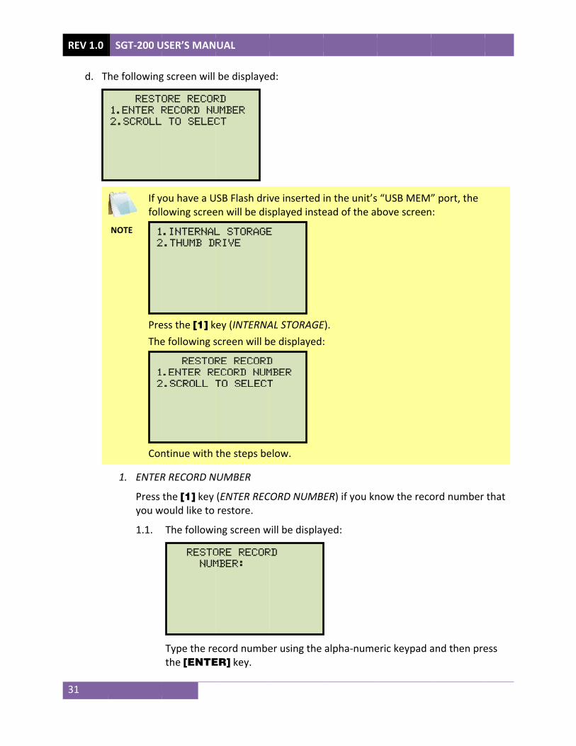
d. T
SGT-200 U
he following
NOTE
If yfoll
PreThe
Con
1. ENTER
Press you w
1.1.
1
2
1
2
REST
1.ENTER R
2.SCROLL
USER’S MAN
g screen will
you have a Ulowing scree
ess the [1] ke following s
ntinue with
R RECORD N
the [1] key would like to
The followi
Type the rethe [ENTE
RESTO
NUM
RESTOR
.ENTER RE
2.SCROLL T
.INTERNAL
2.THUMB DR
ORE RECOR
RECORD NU
TO SELEC
UAL
be displaye
USB Flash driven will be dis
ey (INTERNAscreen will b
the steps be
NUMBER
(ENTER RECrestore.
ng screen w
ecord numbeER] key.
ORE RECOR
MBER:
RE RECORD
ECORD NUM
TO SELECT
L STORAGE
RIVE
RD
UMBER
CT
d:
ve inserted splayed inste
AL STORAGE
be displayed:
elow.
CORD NUMB
will be display
er using the
RD
D
MBER
T
E
in the unit’sead of the a
E). :
ER) if you kn
yed:
alpha-nume
“USB MEM”bove screen
now the reco
eric keypad a
” port, the n:
ord number
and then pre
that
ess
SGT-200 USER’S MANUAL REV 1.0
32
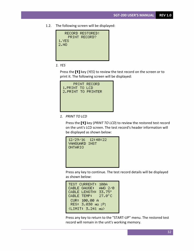
1.2. The following screen will be displayed:
1. YES
Press the [1] key (YES) to review the test record on the screen or to print it. The following screen will be displayed:
1. PRINT TO LCD
Press the [1] key (PRINT TO LCD) to review the restored test record on the unit's LCD screen. The test record's header information will be displayed as shown below:
Press any key to continue. The test record details will be displayed as shown below:
Press any key to return to the "START-UP" menu. The restored test record will remain in the unit's working memory.
TEST CURRENT: 100A
CABLE GAUGE: AWG 2/0
CABLE LENGTH: 33.75'
CABLE TEMP: 27.0°C CUR: 100.00 A
RES: 3.030 mΩ [P] (LIMIT: 3.241 mΩ)
12/29/16 12:40:22
VANGUARD INST
ONTARIO
PRINT RECORD
1.PRINT TO LCD
2.PRINT TO PRINTER
RECORD RESTORED!
PRINT RECORD?
1.YES
2.NO

REV 1.0 SGT-200 USER’S MANUAL
33
2. PRINT TO PRINTER
Press the [2] key (PRINT TO PRINTER) to print the restored test record on the unit's built-in thermal printer. The rest results will be printed on the printer and you will be returned to the "START-UP" menu. The restored test record will remain in the unit's working memory.
2. NO
Press the [2] key (NO) if you do not want to review or print the restored test record. The test record will be restored to the working memory and you will be returned to the "START-UP" menu.
2. SCROLL TO SELECT
Press the [2] key (SCROLL TO SELECT) to scroll through a directory of the stored test records.
2.1. The following screen will be displayed:
Press the [] key or the [] key to display the next or previous test record, respectively.
The test record's header information will be displayed as shown below:
When you have located the test record that you would like to restore,
press the [ENTER] key. Continue to step 1.2 on page 32.
#1 12/29/16 12:40
VANGUARD INST
ONTARIO
RECORDS DIRECTORY
"UP" TO SCROLL FWD
"DWN" TO SCROLL RVS

SGT-200 USER’S MANUAL REV 1.0
34
3.7.4. Restoring a Test Record From a USB Flash Drive Use the steps below to restore a test record from a USB Flash drive to the SGT-200’s working memory:
a. Make sure the USB Flash drive containing the test record(s) is inserted in the unit’s USB Flash drive port (“USB MEM” port). Then start from the “START-UP” menu:
Press the [3] key (SETUP).
b. The following screen will be displayed:
Press the [3] key (SAVE/RESTORE RECORD)
c. The following screen will be displayed:
Press the [1] key (RESTORE RECORD).
1. RESTORE RECORD 2. SAVE RECORD 3. RECORD DIRECTORY 4. ERASE RECORD 5. COPY to THUMB DRIVE
1. RECORD ID 2. REVIEW RECORD 3. SAVE/RESTORE RECORD 4. set time 5. set language 6. CAL NOTICE ON/OFF 7. SET UNITS
1.CERT TEST
2.QUICK TST
3.SETUP time: 10:11:12 23°C
date: 12/29/16 73°F
REV 1.0 SGT-200 USER’S MANUAL
35
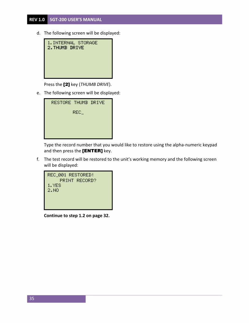
d. The following screen will be displayed:
Press the [2] key (THUMB DRIVE).
e. The following screen will be displayed:
Type the record number that you would like to restore using the alpha-numeric keypad and then press the [ENTER] key.
f. The test record will be restored to the unit’s working memory and the following screen will be displayed:
Continue to step 1.2 on page 32.
REC_001 restored!
PRINT RECORD?
1.YES
2.NO
RESTORE THUMB DRIVE
REC_
1.INTERNAL STORAGE
2.THUMB DRIVE
SGT-200 USER’S MANUAL REV 1.0
36
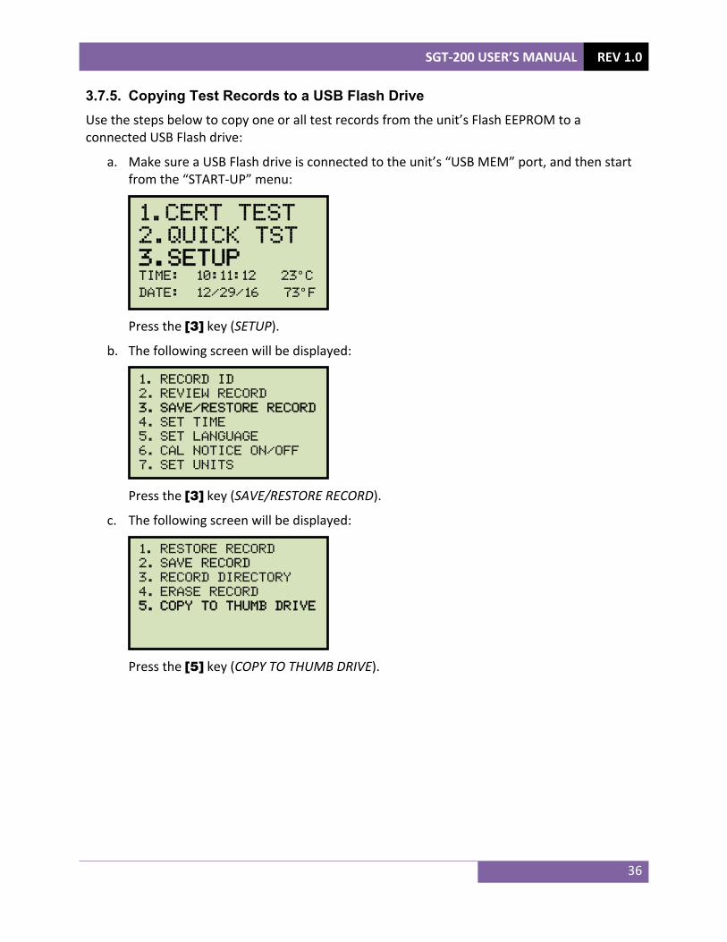
3.7.5. Copying Test Records to a USB Flash Drive Use the steps below to copy one or all test records from the unit’s Flash EEPROM to a connected USB Flash drive:
a. Make sure a USB Flash drive is connected to the unit’s “USB MEM” port, and then start from the “START-UP” menu:
Press the [3] key (SETUP).
b. The following screen will be displayed:
Press the [3] key (SAVE/RESTORE RECORD).
c. The following screen will be displayed:
Press the [5] key (COPY TO THUMB DRIVE).
1. RESTORE RECORD 2. SAVE RECORD 3. RECORD DIRECTORY 4. ERASE RECORD 5. COPY to THUMB DRIVE
1. RECORD ID 2. REVIEW RECORD 3. SAVE/RESTORE RECORD 4. set time 5. set language 6. CAL NOTICE ON/OFF 7. SET UNITS
1.CERT TEST
2.QUICK TST
3.SETUP time: 10:11:12 23°C
date: 12/29/16 73°F

REV 1.0 SGT-200 USER’S MANUAL
37
d. The following screen will be displayed:
1. COPY SINGLE RECORD
Press the [1] key (COPY SINGLE RECORD) to copy a single test record from the unit’s Flash EEPROM to the connected USB Flash drive. The following screen will be displayed:
Type the record number using the alpha-numeric keypad and then press the [ENTER] key. The test record will be copied to the USB Flash drive and the following screen will be displayed:
Press any key to return to the “START-UP” menu.
REC_013 SAVED TO THUMB DRIVE
ENTER RECORD NUMBER
TO COPY TO FLASH DRV
NUMBER:
COPY REC TO THUMB DRV
1.COPY SINGLE RECORD
2.COPY ALL RECORDS

SGT-200 USER’S MANUAL REV 1.0
38
2. COPY ALL RECORDS
Press the [2] key (COPY ALL RECORDS) to copy all test records from the SGT-200’s Flash EEPROM to the connected USB Flash drive. All test records will be copied from the unit to the connected USB Flash drive. The following screen will be displayed when the process is finished:
Press any key to return to the “START-UP” menu.
ALL RECORDS HAVE BEEN
TRANSFERRED TO THUMB
DRIVE!

REV 1.0
39
3.7.6. PUse the sEEPROM
a. St
P
b. T
P
c. T
P
IfIf
SGT-200 U
Printing thesteps below or on a con
tart from th
ress the [3]
he following
ress the [3]
he following
NOTE
Opcon
ress the [3]
f a USB Flashf a USB Flash
1. RESTOR2. SAVE R3. RECORD4. ERASE 5. COPY t
1. RECORD2. REVIEW3. SAVE/R4. set ti5. set la6. CAL NO
1.CER
2.QUI
3.SETtime: 10
date: 12
USER’S MAN
e Test Recoto print a dinected USB
e “START-UP
key (SETUP
g screen will
key (SAVE/R
g screen will
tion 5 (COPYnnected to t
key (RECOR
h drive is conh drive is no
RE RECORD
RECORD
D DIRECTO
RECORD
to THUMB
D ID
W RECORD
RESTORE R
ime
anguage
OTICE ON/
RT TES
ICK TS
TUP 0:11:12
2/29/16
UAL
ord Directoirectory of thFlash drive:
P” menu:
).
be displaye
RESTORE RE
be displaye
Y TO THUMBhe unit.
RD DIRECTOR
nnected to tt connected
D
ORY
DRIVE
RECORD
/OFF
ST
ST
23°C
73°F
ory he test reco
d:
ECORD).
d:
B DRIVE) is li
RY).
the unit, cond to the unit
rds stored in
sted only if
ntinue to ste, continue t
n the SGT-20
a USB Flash
ep d. o step e.
00’s Flash
drive is

SGT-200 USER’S MANUAL REV 1.0
40
d. The following screen will be displayed:
1. INTERNAL DIRECTORY
Press the [1] key (INTERNAL DIRECTORY) to print a directory of the test records stored in the unit's internal memory. Continue to step e.
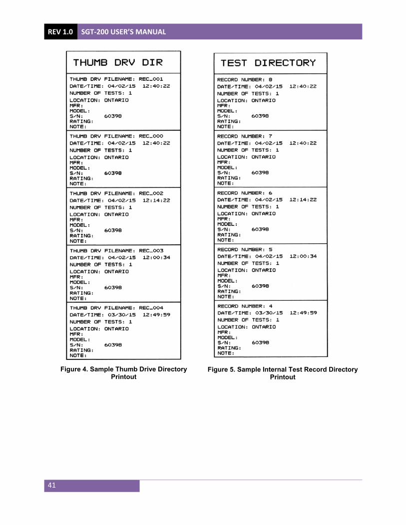
2. THUMB DRIVE DIR
Press the [2] key (THUMB DRIVE DIR) to print a directory of the test records stored on the connected USB Flash drive. The directory will be printed on the built-in thermal printer and you will be returned to the "START-UP" menu. A sample thumb drive directory printout is shown in Figure 4.
e. The following screen will be displayed:
Press the [1] key (FULL DIRECTORY) to print a complete directory of all test records stored in the unit's internal memory. The directory will be printed on the thermal printer and you will be returned to the "START-UP" menu. A sample internal test record directory printout is shown in Figure 5.
Press the [2] key (SHORT DIRECTORY) to print a directory of the last 10 test records stored in the unit's internal memory. The directory will be printed on the thermal printer and you will be returned to the "START-UP" menu.
PRINT DIRECTORY
1. FULL DIRECTORY
2. SHORT DIRECTORY
1. INTERNAL DIRECTORY
2. THUMB DRIVE DIR
REV 1.0 SGT-200 USER’S MANUAL
41
Figure 4. Sample Thumb Drive Directory
Printout
Figure 5. Sample Internal Test Record Directory
Printout

SGT-200 USER’S MANUAL REV 1.0
42
3.7.7. Erasing Test Records from the Unit's Flash EEPROM Follow the steps below to erase test records from the unit's Flash EEPROM
a. Start from the “START-UP” menu:
Press the [3] key (SETUP).
b. The following screen will be displayed:
Press the [3] key (SAVE/RESTORE RECORD).
c. The following screen will be displayed:
Press the [4] key (ERASE RECORD).
1. RESTORE RECORD 2. SAVE RECORD 3. RECORD DIRECTORY 4. ERASE RECORD 5. COPY to THUMB DRIVE
1. RECORD ID 2. REVIEW RECORD 3. SAVE/RESTORE RECORD 4. set time 5. set language 6. CAL NOTICE ON/OFF 7. SET UNITS
1.CERT TEST
2.QUICK TST
3.SETUP time: 10:11:12 23°C
date: 12/29/16 73°F
REV 1.0
43
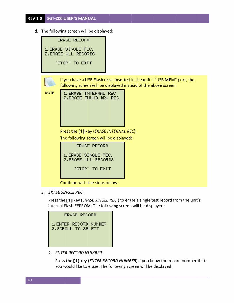
d. T
1
SGT-200 U
he following
NOTE
If yfoll
PreThe
Con
. ERASE SIN
Press the internal F
1. ENTER
Press you w
E
1.ENTE
2.SCRO
1
2
1
2
ERA
1.ERASE S
2.ERASE
"STO
USER’S MAN
g screen will
you have a Ulowing scree
ess the [1] ke following s
ntinue with
NGLE REC.
[1] key (ERAFlash EEPROM
R RECORD N
the [1] key would like to
ERASE REC
ER RECORD
OLL TO SE
ERASE
.ERASE SI
2.ERASE AL
"STOP
.ERASE IN
2.ERASE TH
SE RECORD
SINGLE RE
ALL RECOR
P" TO EXI
UAL
be displaye
USB Flash driven will be dis
ey (ERASE INscreen will b
the steps be
ASE SINGLE M. The follow
NUMBER
(ENTER RECerase. The f
CORD
D NUMBER
ELECT
E RECORD
INGLE REC
LL RECORD
" TO EXIT
NTERNAL R
HUMB DRV
D
EC.
RDS
IT
d:
ve inserted splayed inste
NTERNAL REbe displayed:
elow.
REC.) to erawing screen
CORD NUMBfollowing scr
C.
DS
T
REC
REC
in the unit’sead of the a
EC). :
se a single te will be disp
ER) if you knreen will be
“USB MEM”bove screen
est record frplayed:
now the recodisplayed:
” port, the n:
rom the unit
ord number
t’s
that

NOTE
Type tkeypanumbsectio
The fo
The foerased
Press
REC
ERA
E
You can pressing
the record nad and then ber, you can on 3.7.6.
ollowing scre
ollowing scred:
any key to c
CORD NUMB
ASED!
ERASing
PLEASE W
ERASE RE
NUMBER:
cancel the pg the [STOP
number that press the [Efirst view th
een will be d
een will be d
continue. Yo
ER 8
record
AIT...
CORD
process and P] key.
you would lENTER] key
e test recor
displayed wh
displayed wh
u will be ret
SGT-200
return to th
like to erasey. If you do nd directory u
hile the reco
hen the test
turned to the
USER’S MA
e “START-UP
e using the anot know theusing the ins
rd is being e
record has b
e beginning
NUAL RE
P” menu by
lpha-numere test recordstructions in
erased:
been comple
of step d.
V 1.0
44
ic d
etely

REV 1.0 SGT-200 USER’S MANUAL
45
2. SCROLL TO SELECT
Press the [2] key (SCROLL TO SELECT) to scroll through the test record directory and locate the test record that you would like to erase. The following screen will be displayed:
Press the [] or [] key to scroll through the test record directory. The test record header will be displayed as shown:
You can continue to scroll through the record directory by pressing the [∧] and [∨] keys. Once you have located the test record you would like to erase, press the [ENTER] key. The selected test record will be erased and the following screen will be displayed:
Press any key to continue. You will be returned to the beginning of step d.
RECORD NUMBER 9
ERASED!
#1 03/09/15 09:55
VIC
LAB
RECORDS DIRECTORY
"UP" TO SCROLL FWD
"DWN" TO SCROLL RVS

SGT-200 USER’S MANUAL REV 1.0
46
2. ERASE ALL RECORDS
Press the [2] key (ERASE ALL RECORDS) to erase all the test records from the unit’s internal Flash EEPROM. The following warning screen will be displayed:
You can press the [STOP] key to cancel the process and return to the “START-UP” menu.
Press the [ENTER] key to proceed with deleting all the test records from the unit’s Flash EEPROM. The following screen will be displayed during the erasure process:
The following screen will be displayed when all test records have been completely erased:
Press any key to return to the “START-UP” menu.
RECORDS ERASED!
ERASing recordS
PLEASE WAIT...
ERASE ALL RECORDS!
ARE YOU SURE?
"ENTER" To CONTINUE.

REV 1.0 SGT-200 USER’S MANUAL
47
3.7.8. Erasing Test Records from a USB Flash Drive Follow the steps below to erase test records from a connected USB Flash drive:
a. Make sure a USB Flash drive is connected to the unit’s “USB MEM” port, and then start from the “START-UP” menu:
Press the [3] key (SETUP).
b. The following screen will be displayed:
Press the [3] key (SAVE/RESTORE RECORD).
c. The following screen will be displayed:
Press the [4] key (ERASE RECORD).
d. The following screen will be displayed:
Press the [2] key (ERASE THUMB DRV REC).
1.ERASE INTERNAL REC
2.ERASE THUMB DRV REC
1. RESTORE RECORD 2. SAVE RECORD 3. RECORD DIRECTORY 4. ERASE RECORD 5. COPY to THUMB DRIVE
1. RECORD ID 2. REVIEW RECORD 3. SAVE/RESTORE RECORD 4. set time 5. set language 6. CAL NOTICE ON/OFF 7. SET UNITS
1.CERT TEST
2.QUICK TST
3.SETUP time: 10:11:12 23°C
date: 12/29/16 73°F

SGT-200 USER’S MANUAL REV 1.0
48
e. The following screen will be displayed:
1. ERASE SINGLE REC.
Press the [1] key (ERASE SINGLE REC.) to erase a single test record from the connected USB Flash drive. The following screen will be displayed:
Type the record number that you would like to erase using the alpha-numeric keypad and then press the [ENTER] key. The test record will be erased from the USB Flash drive and the following screen will be displayed:
Press any key to continue. You will be returned to the beginning of step e. Press the [STOP] key to return to the “START-UP” menu.
2. ERASE ALL RECORDS
Press the [2] key (ERASE ALL RECORDS) to delete all test records from the connected USB Flash drive. The following warning screen will be displayed:
ERASE ALL THUMB DRIVE
RECORDS!
ARE YOU SURE?
"ENTER" TO CONTINUE.
THUMB DRIVE RE001
ERASED!
ERASE THUMB DRIVE
REC_
ERASE RECORD
1.ERASE SINGLE REC.
2.ERASE ALL RECORDS
"STOP" TO EXIT

REV 1.0 SGT-200 USER’S MANUAL
49
Press the [STOP] key if you do not want to erase all the test records. You will be returned to the “START-UP” menu.
Press the [ENTER] key to proceed with deleting all the test records from the connected USB Flash drive. The following screen will be displayed when all the records have been erased:
Press any key to return to the “START-UP” menu.
all thumb drive
records erased!
SGT-200 USER’S MANUAL REV 1.0
50
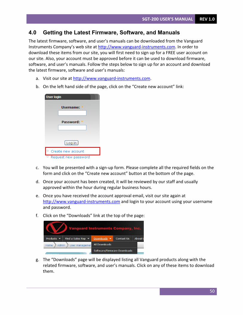
4.0 Getting the Latest Firmware, Software, and Manuals The latest firmware, software, and user’s manuals can be downloaded from the Vanguard Instruments Company’s web site at http://www.vanguard-instruments.com. In order to download these items from our site, you will first need to sign up for a FREE user account on our site. Also, your account must be approved before it can be used to download firmware, software, and user’s manuals. Follow the steps below to sign up for an account and download the latest firmware, software and user’s manuals:
a. Visit our site at http://www.vanguard-instruments.com.
b. On the left hand side of the page, click on the “Create new account” link:
c. You will be presented with a sign-up form. Please complete all the required fields on the
form and click on the “Create new account” button at the bottom of the page.
d. Once your account has been created, it will be reviewed by our staff and usually approved within the hour during regular business hours.
e. Once you have received the account approval email, visit our site again at http://www.vanguard-instruments.com and login to your account using your username and password.
f. Click on the “Downloads” link at the top of the page:
g. The “Downloads” page will be displayed listing all Vanguard products along with the
related firmware, software, and user’s manuals. Click on any of these items to download them.

1520 S. Hellman Ave • Ontario, CA 91761 • USA
Phone: 909-923-9390 • Fax: 909-923-9391 www.vanguard-instruments.com
Copyright © 2017 by Vanguard Instruments Company, Inc.
SGT-200 User’s Manual • Revision 1.0 • January 3, 2017 • TA