Embed Size (px)
Citation preview
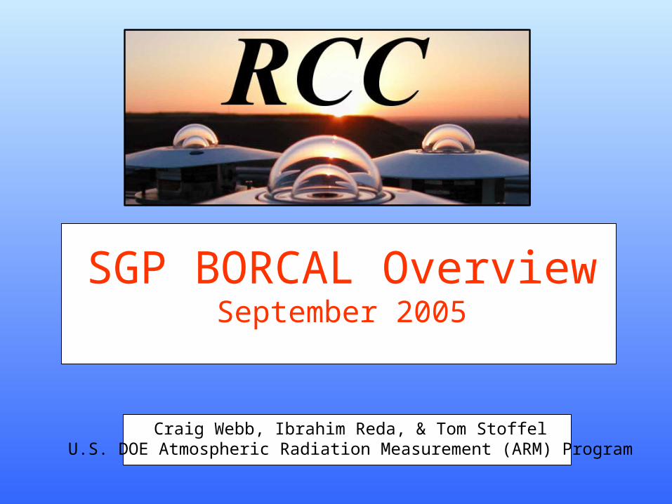
SGP BORCAL OverviewSeptember 2005
Craig Webb, Ibrahim Reda, & Tom StoffelU.S. DOE Atmospheric Radiation Measurement (ARM) Program
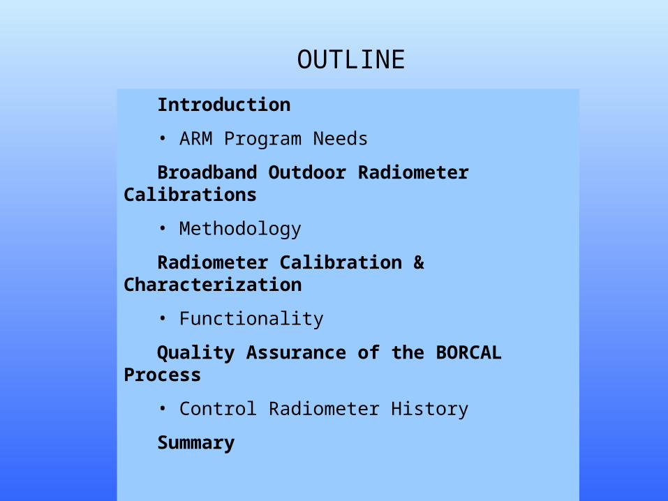
OUTLINE
Introduction
• ARM Program Needs
Broadband Outdoor Radiometer Calibrations
• Methodology
Radiometer Calibration & Characterization
• Functionality
Quality Assurance of the BORCAL Process
• Control Radiometer History
Summary
ARMARMAtmospheric Radiation MeasurementAtmospheric Radiation Measurement
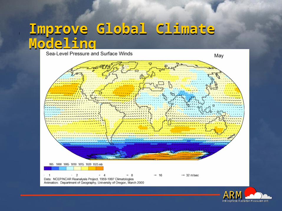
Improve Global Climate ModelingImprove Global Climate Modeling

ARMARMAtmospheric Radiation MeasurementAtmospheric Radiation Measurement
Advance Climate Change Research
by Providing
Accurate Measurements
Most ambitious meteorological measurement program since the International Geophysical Year of
1957.
ARMARMAtmospheric Radiation MeasurementAtmospheric Radiation Measurement
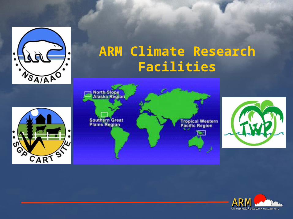
ARM Climate Research Facilities
ARMARMAtmospheric Radiation MeasurementAtmospheric Radiation Measurement
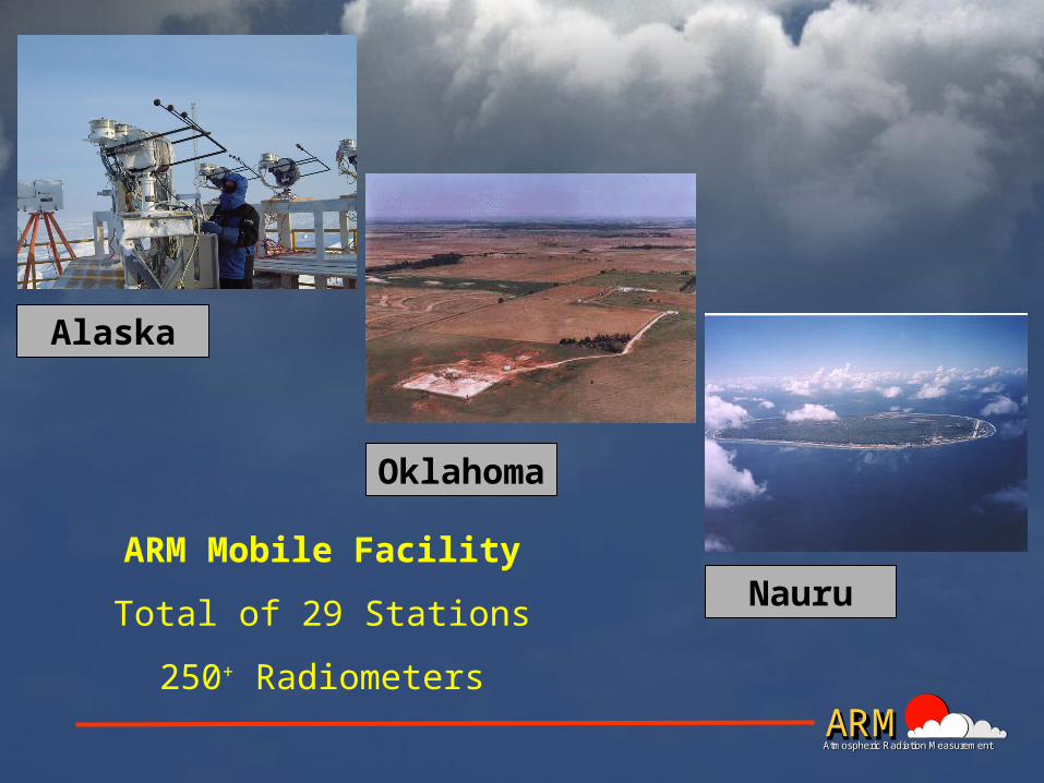
Alaska
Oklahoma
NauruARM Mobile Facility
Total of 29 Stations
250+ Radiometers
ARMARMAtmospheric Radiation MeasurementAtmospheric Radiation Measurement
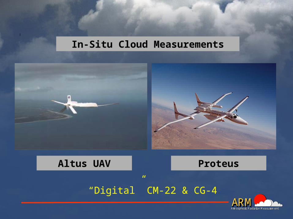
In-Situ Cloud Measurements
ProteusAltus UAV
“Digital” CM-22 & CG-4
ARMARMAtmospheric Radiation MeasurementAtmospheric Radiation Measurement
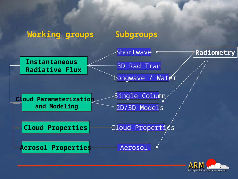
Instantaneous Radiative Flux
Cloud Parameterization and Modeling
Cloud Properties
Aerosol Properties
Shortwave
3D Rad Tran
Longwave / Water
Single Column
2D/3D Models
Cloud Properties
Aerosol
Working groups Subgroups
Radiometry
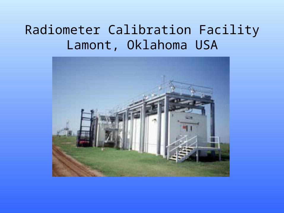
Radiometer Calibration FacilityLamont, Oklahoma USA
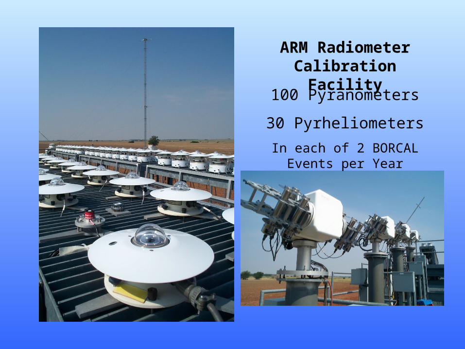
ARM Radiometer Calibration Facility
100 Pyranometers
30 Pyrheliometers
In each of 2 BORCAL Events per Year
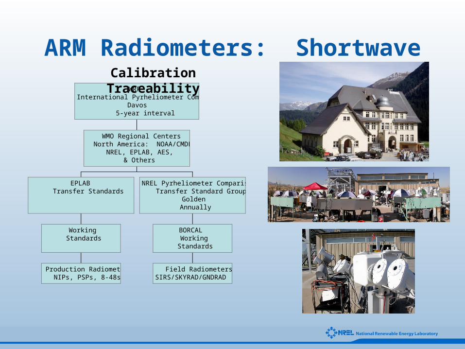
Production RadiometersNIPs, PSPs, 8-48s
WorkingStandards
EPLABTransfer Standards
Field RadiometersSIRS/SKYRAD/GNDRAD
BORCALWorking
Standards
NREL Pyrheliometer ComparisonsTransfer Standard Group
GoldenAnnually
WMO Regional CentersNorth America: NOAA/CMDL
NREL, EPLAB, AES,& Others
WRRInternational Pyrheliometer Comparisons
Davos5-year interval
ARM Radiometers: ShortwaveCalibration Traceability
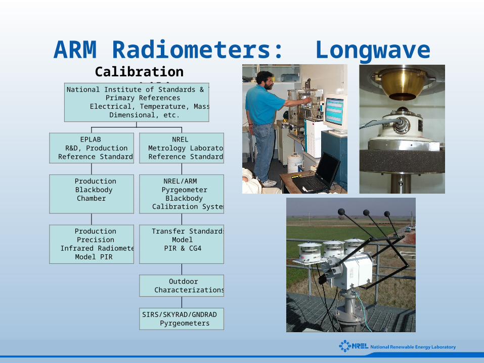
ARM Radiometers: LongwaveCalibration Traceability
ProductionPrecision
Infrared RadiometerModel PIR
ProductionBlackbodyChamber
EPLABR&D, Production
Reference Standards
SIRS/SKYRAD/GNDRADPyrgeometers
OutdoorCharacterizations
Transfer StandardsModel
PIR & CG4
NREL/ARMPyrgeometer
BlackbodyCalibration System
NRELMetrology LaboratoryReference Standards
National Institute of Standards & TechnologyPrimary References
Electrical, Temperature, MassDimensional, etc.
Broadband
Outdoor
Radiometer
CALibration
Based on component summation…
BORCAL is the Process

Component Summation Technique
Direct Beam(Cavity Radiometer)
* Cos(Z)
=+
Reference Diffuse(Shaded Pyranometer)
GlobalReference
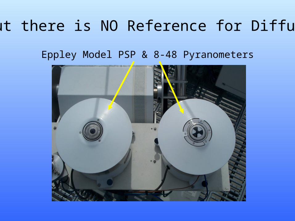
But there is NO Reference for Diffuse!
Eppley Model PSP & 8-48 Pyranometers
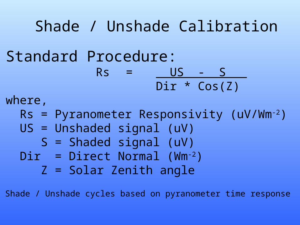
Shade / Unshade Calibration
Standard Procedure:Rs = US - S
Dir * Cos(Z)where, Rs = Pyranometer Responsivity (uV/Wm-2) US = Unshaded signal (uV) S = Shaded signal (uV) Dir = Direct Normal (Wm-2) Z = Solar Zenith angle
Shade / Unshade cycles based on pyranometer time response
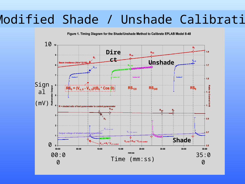
Time (mm:ss)00:00 35:00
Signal
(mV)
0
10Direct
Unshade
Shade
Modified Shade / Unshade Calibration
RCC is the Software Mechanism
Radiometer
Calibration &
Characterization
Used to control the BORCAL process with Lab Windows and Access programs…
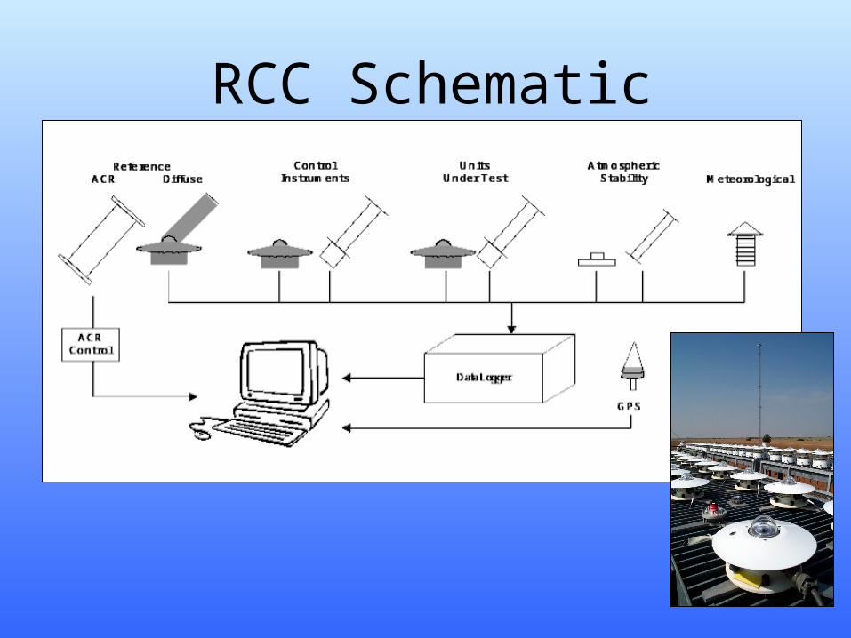
RCC Schematic
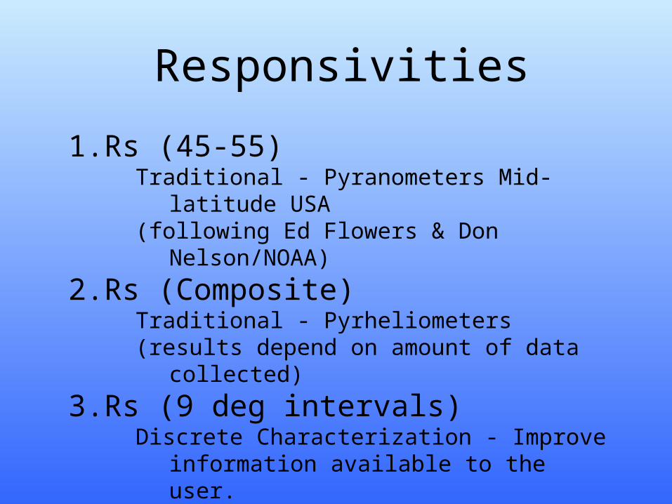
Responsivities
1. Rs (45-55)Traditional - Pyranometers Mid-latitude USA(following Ed Flowers & Don Nelson/NOAA)
2. Rs (Composite)Traditional - Pyrheliometers(results depend on amount of data collected)
3. Rs (9 deg intervals)Discrete Characterization - Improve information
available to the user.
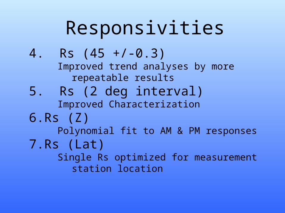
Responsivities4. Rs (45 +/-0.3)
Improved trend analyses by more repeatable results
5. Rs (2 deg interval)Improved Characterization
6. Rs (Z)Polynomial fit to AM & PM responses
7. Rs (Lat)Single Rs optimized for measurement station
location
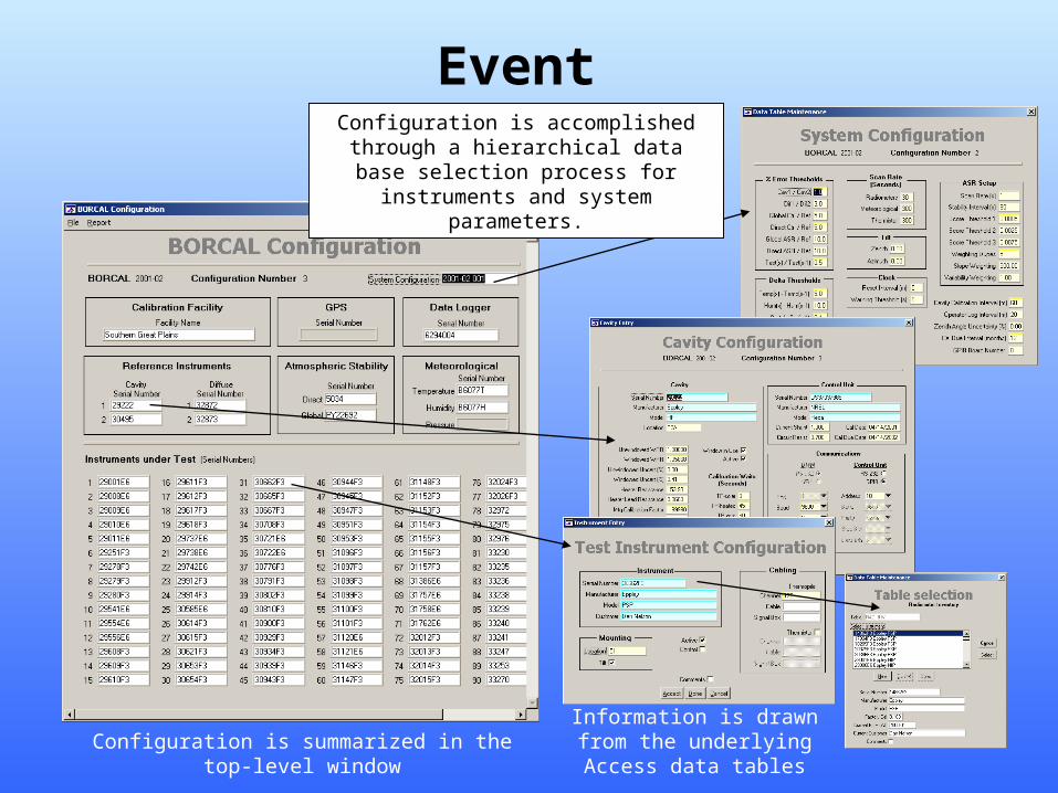
Event ConfigurationConfiguration is accomplished through a
hierarchical data base selection process for instruments and system parameters.
Configuration is summarized in the top-level windowInformation is drawn from the underlying Access data tables
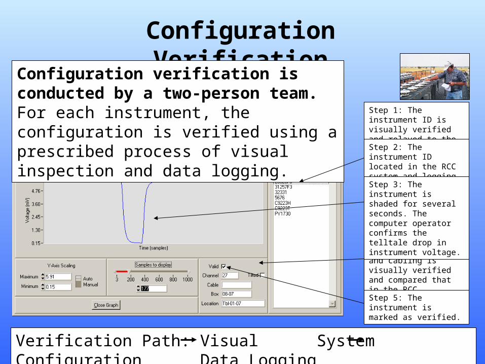
Configuration Verification
Configuration verification is conducted by a two-person team. For each instrument, the configuration is verified using a prescribed process of visual inspection and data logging.
Step 1: The instrument ID is visually verified and relayed to the computer operator.
Verification Path: Visual System Configuration Data Logging
Step 2: The instrument ID located in the RCC system and logging commenced.
Step 4: The instrument location and cabling is visually verified and compared that in the RCC configuration.
Step 3: The instrument is shaded for several seconds. The computer operator confirms the telltale drop in instrument voltage.
Step 5: The instrument is marked as verified.
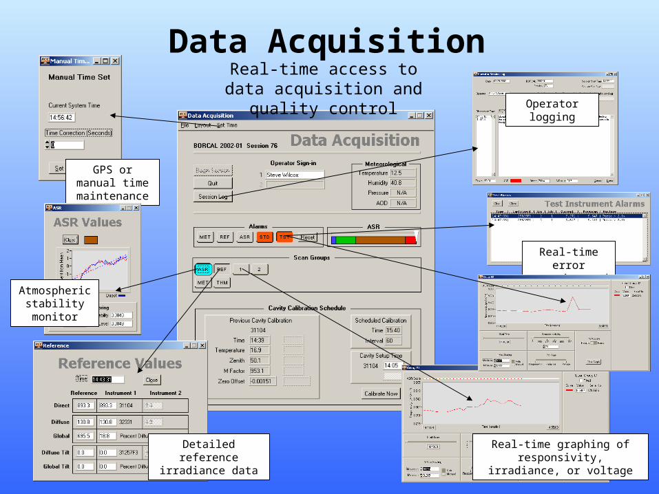
Data Acquisition
Operator logging
GPS or manual time maintenance
Atmospheric stability monitor
Real-time graphing of responsivity, irradiance, or voltage
Real-time error trapping and
diagnosis
Detailed reference irradiance data
Real-time access to data acquisition and quality control
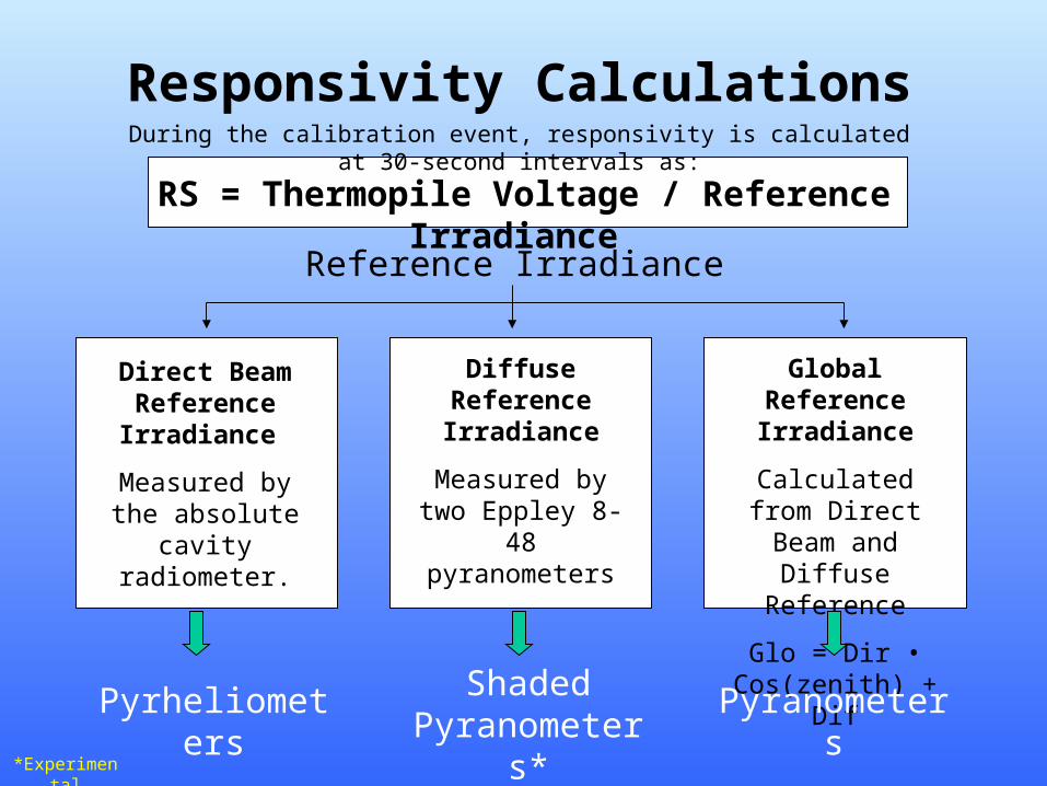
Responsivity CalculationsDuring the calibration event, responsivity is calculated at 30-second intervals as:
RS = Thermopile Voltage / Reference Irradiance
Direct Beam Reference
Irradiance
Measured by the absolute cavity
radiometer.
Diffuse Reference Irradiance
Measured by two Eppley 8-48
pyranometers
Global Reference Irradiance
Calculated from Direct Beam and
Diffuse Reference
Glo = Dir • Cos(zenith) + Dif
Pyrheliometers Shaded Pyranometers*
Pyranometers
*Experimental
Reference Irradiance
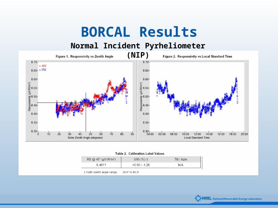
BORCAL ResultsNormal Incident Pyrheliometer (NIP)
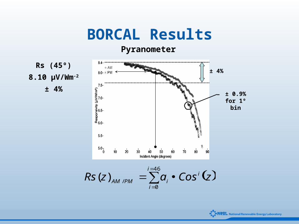
BORCAL ResultsPyranometer
± 4%
± 0.9% for 1º bin
Rs (45º)
8.10 µV/Wm-2
± 4%
( )∑=
=
•=46
0/)(
i
i
i
iPMAM zCosazRs
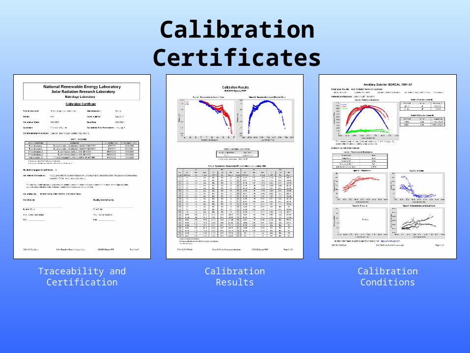
Calibration Certificates
Traceability and Certification Calibration ConditionsCalibration Results
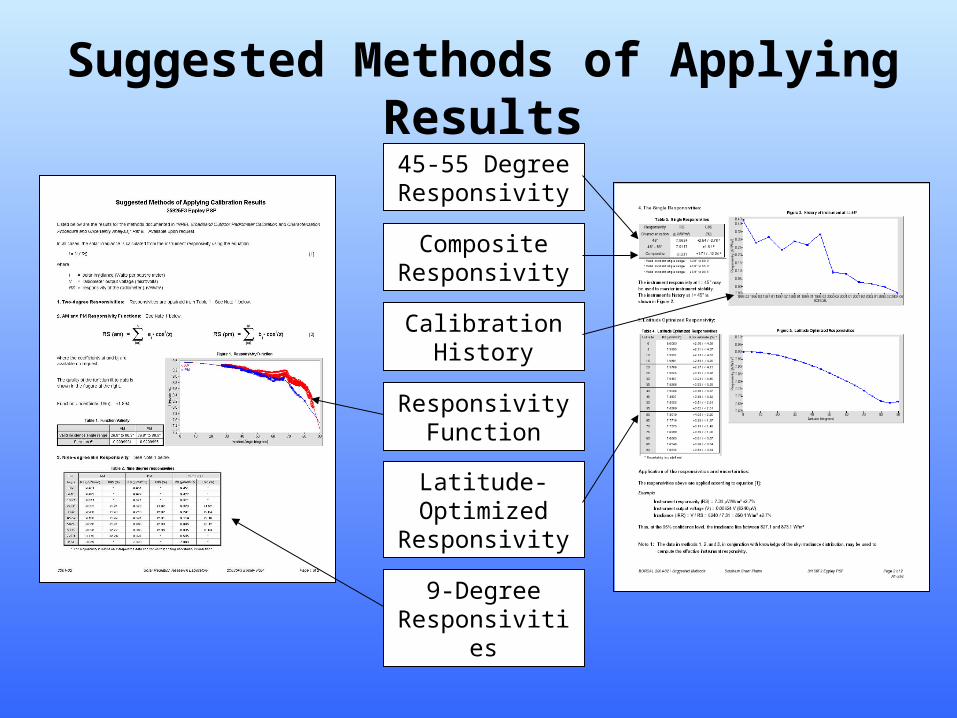
Suggested Methods of Applying Results
45-55 Degree Responsivity
Composite Responsivity
Calibration History
Latitude-Optimized
Responsivity
Responsivity Function
9-Degree Responsivities
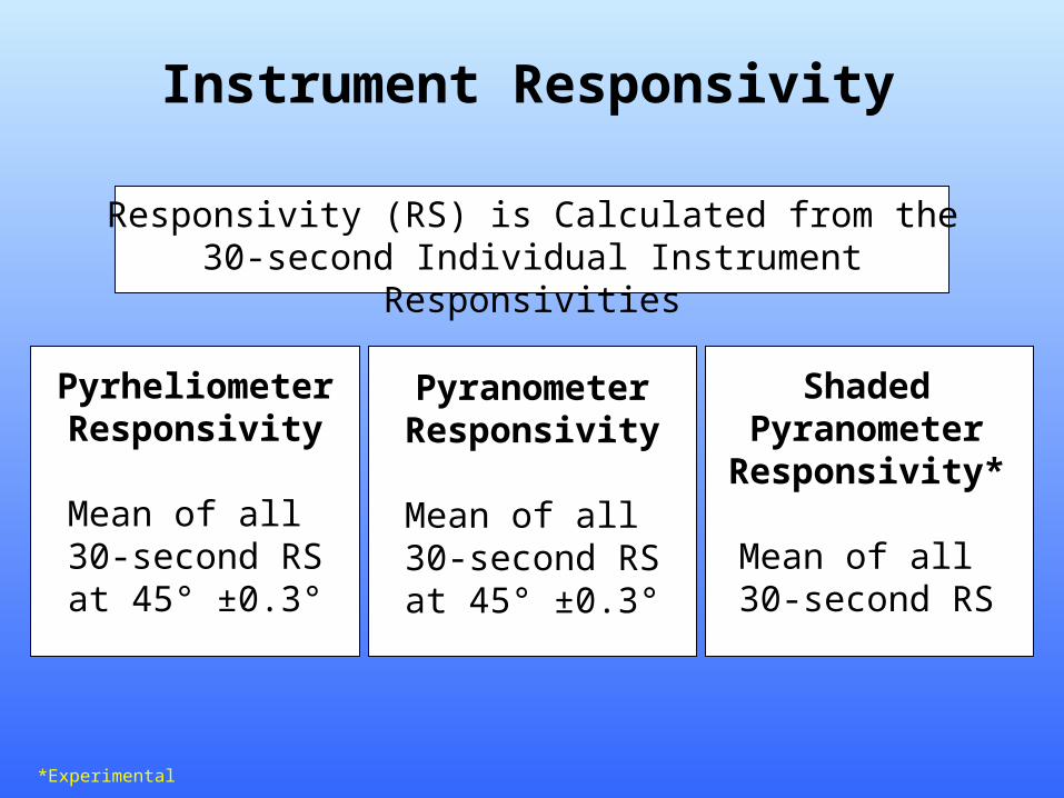
Instrument Responsivity
Pyranometer Responsivity
Mean of all 30-second RS at
45° ±0.3°
Responsivity (RS) is Calculated from the 30-second Individual Instrument Responsivities
Shaded Pyranometer Responsivity*
Mean of all 30-second RS
Pyrheliometer Responsivity
Mean of all 30-second RS at
45° ±0.3°
*Experimental
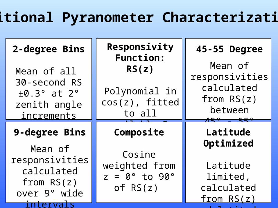
Additional Pyranometer Characterizations
2-degree Bins
Mean of all 30-second RS ±0.3°
at 2° zenith angle increments
Responsivity Function: RS(z)
Polynomial in cos(z), fitted to all available
2-degree responsivities
45-55 Degree
Mean of responsivities
calculated from RS(z) between
45° - 55°
9-degree Bins
Mean of responsivities
calculated from RS(z) over 9° wide
intervals
Composite
Cosine weighted from z = 0° to 90°
of RS(z)
Latitude Optimized
Latitude limited, calculated from
RS(z) and latitude
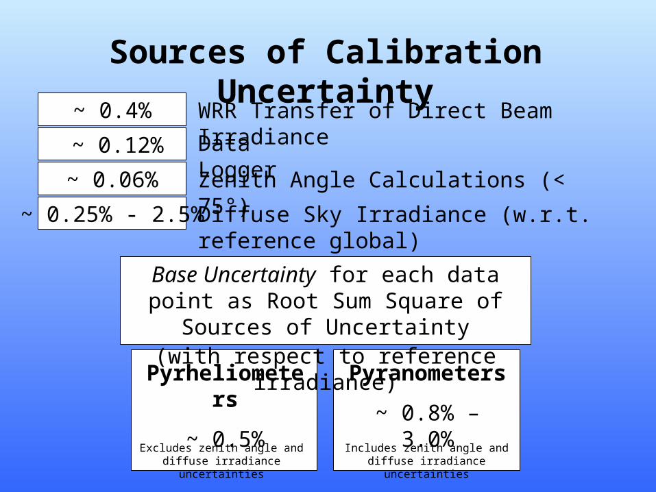
~ 0.25% - 2.5%
~ 0.06%
~ 0.4% WRR Transfer of Direct Beam Irradiance
Sources of Calibration Uncertainty
Data Logger
Zenith Angle Calculations (< 75°)
Diffuse Sky Irradiance (w.r.t. reference global)
Base Uncertainty for each data point as Root Sum Square of Sources of Uncertainty(with respect to reference irradiance)
Pyrheliometers
~ 0.5%
Pyranometers
~ 0.8% – 3.0%
~ 0.12%
Excludes zenith angle and diffuse irradiance uncertainties
Includes zenith angle and diffuse irradiance uncertainties
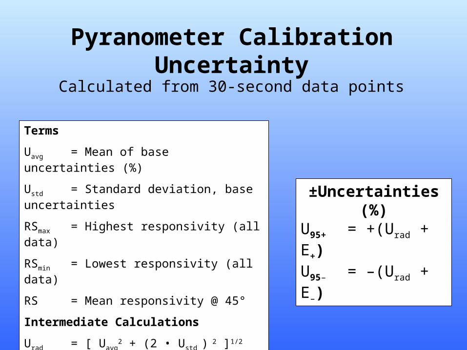
Pyranometer Calibration Uncertainty
Terms
Uavg = Mean of base uncertainties (%)
Ustd = Standard deviation, base uncertainties
RSmax = Highest responsivity (all data)
RSmin = Lowest responsivity (all data)
RS = Mean responsivity @ 45°
Intermediate Calculations
Urad = [ Uavg2 + (2 • Ustd )
2 ]1/2
E+ = 100 • (RSmax – RS) / RS
E– = 100 • (RS – RSmin) / RS
±Uncertainties (%)U95+ = +(Urad + E+)U95– = –(Urad + E–)
Calculated from 30-second data points
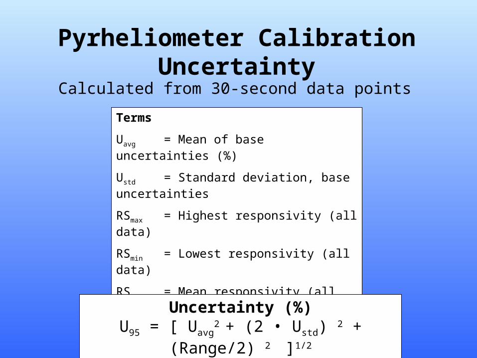
Pyrheliometer Calibration Uncertainty
Terms
Uavg = Mean of base uncertainties (%)
Ustd = Standard deviation, base uncertainties
RSmax = Highest responsivity (all data)
RSmin = Lowest responsivity (all data)
RS = Mean responsivity (all data)
Intermediate Calculations
Range = 100 • (RSmax – RSmin) / RS
Uncertainty (%)U95 = [ Uavg
2 + (2 • Ustd) 2 + (Range/2) 2
]1/2
Calculated from 30-second data points
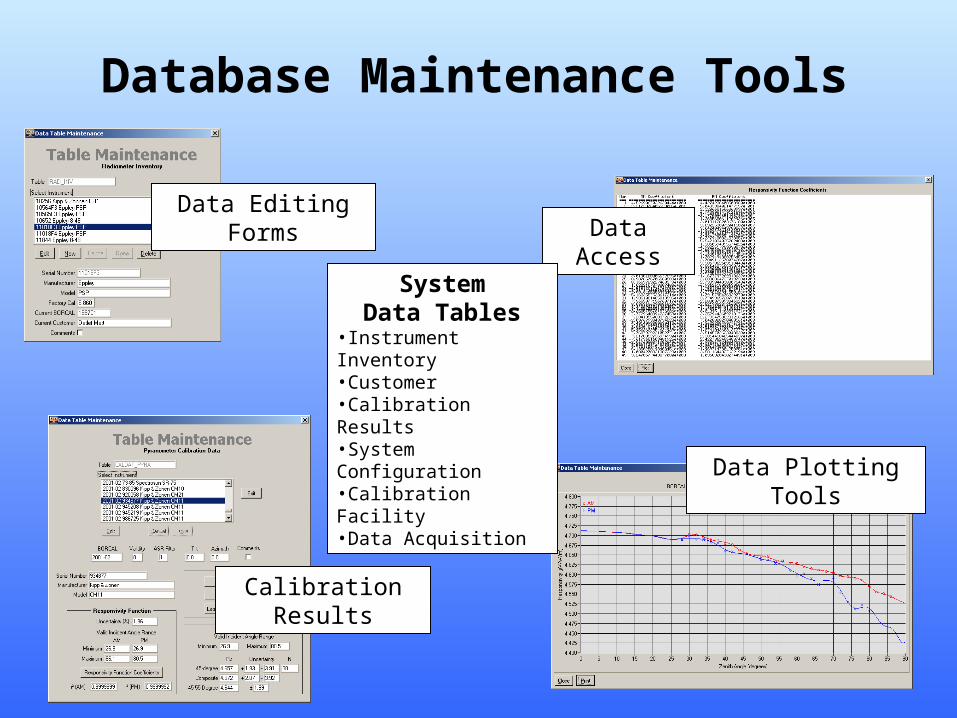
Database Maintenance Tools
Data Editing FormsData Access
Data Plotting Tools
Calibration Results
SystemData Tables
•Instrument Inventory•Customer•Calibration Results•System Configuration•Calibration Facility•Data Acquisition
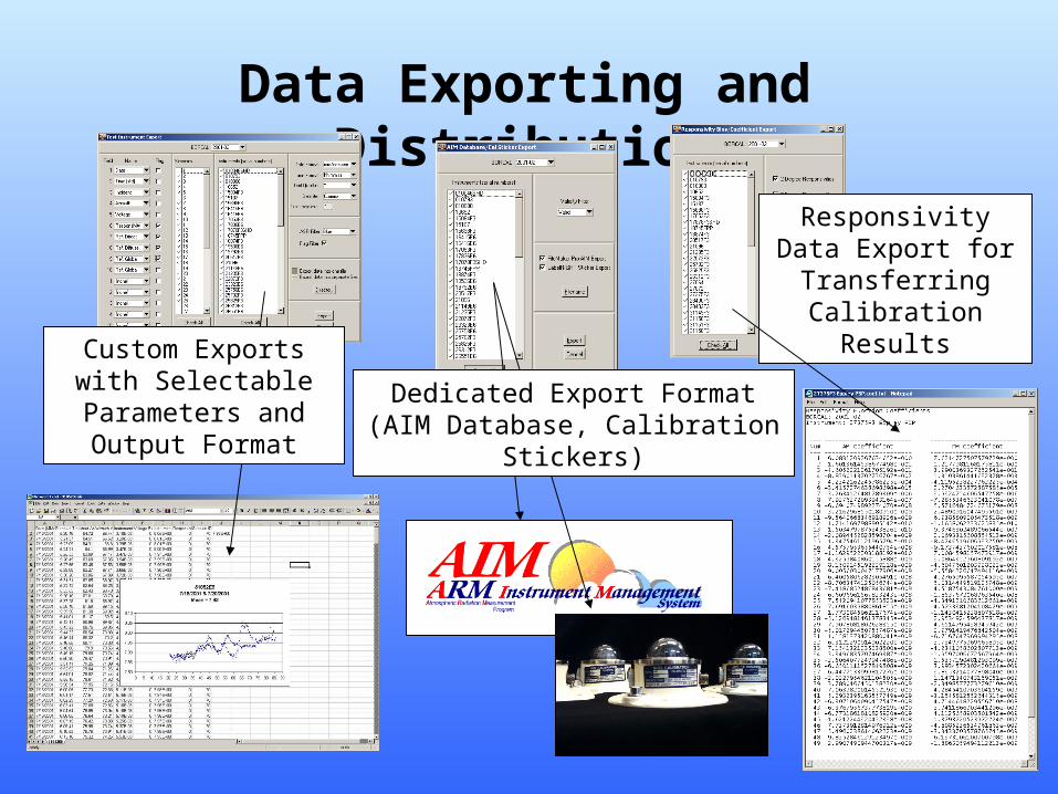
Data Exporting and Distribution
Responsivity Data Export for Transferring
Calibration Results
Custom Exports with Selectable Parameters and
Output FormatDedicated Export Format
(AIM Database, Calibration Stickers)
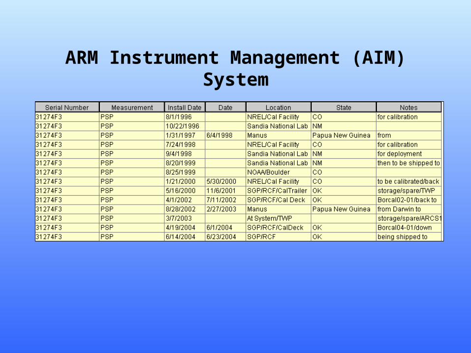
ARM Instrument Management (AIM) System
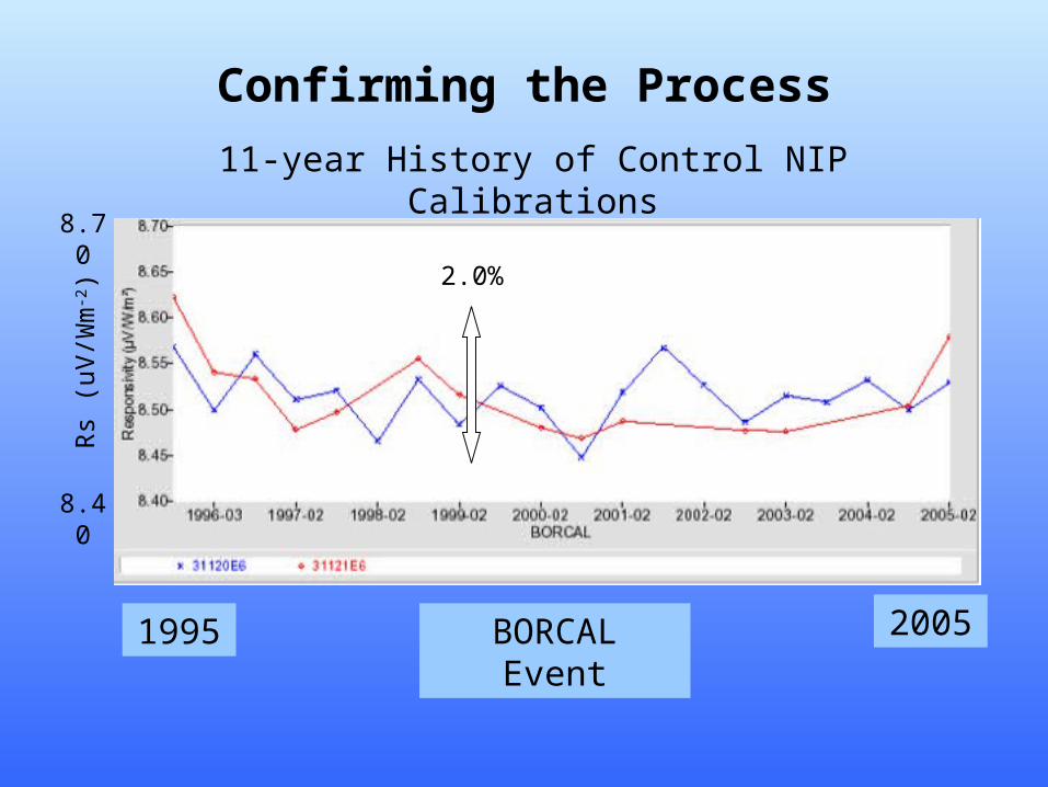
Confirming the Process
11-year History of Control NIP Calibrations
BORCAL Event1995 2005
8.70
8.40
Rs
(uV
/Wm
-2) 2.0%
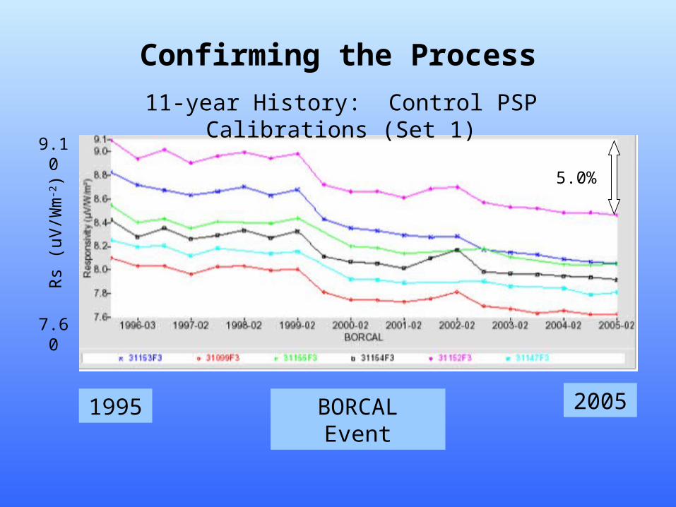
Confirming the Process
11-year History: Control PSP Calibrations (Set 1)
BORCAL Event1995 2005
9.10
7.60
Rs
(uV
/Wm
-2) 5.0%
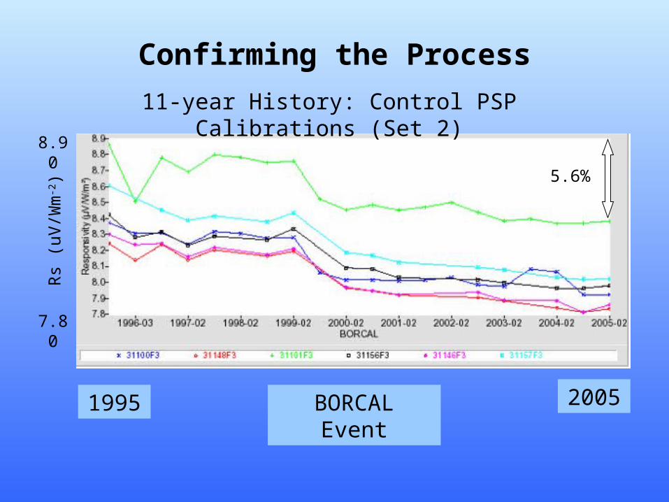
Confirming the Process
11-year History: Control PSP Calibrations (Set 2)
BORCAL Event1995 2005
8.90
7.80
Rs
(uV
/Wm
-2) 5.6%
Summary• The Atmospheric Radiation Measurement (ARM) Program needs accurate broadband irradiance data from three climatic regions.
• NREL has developed RCC software to semi-automate the BORCAL process for hundreds of shortwave radiometer calibrations each year.
• The AIM Database contains BORCAL and deployment information for all ARM radiometers (http://www.nrel.gov/aim)
• Control Radiometer calibration history shows long-term performance of BORCAL process and radiometer responsivities.

Thanks!
Questionsfor Craig or Reda?
More information available fromhttp://www.arm.gov