Embed Size (px)
Citation preview
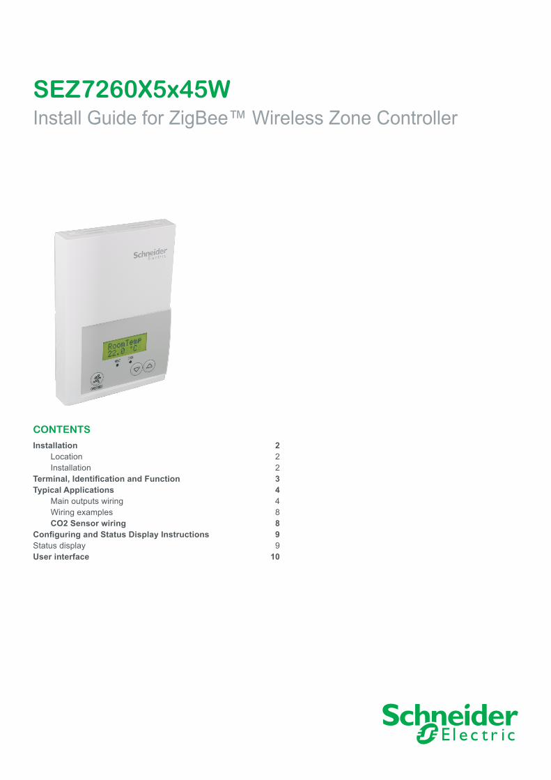
SEZ7260X5x45WInstall Guide for ZigBee™ Wireless Zone Controller
CONTENTS
Installation 2 Location 2 Installation 2Terminal, Identification and Function 3Typical Applications 4 Main outputs wiring 4 Wiring examples 8 CO2 Sensor wiring 8Configuring and Status Display Instructions 9Status display 9User interface 10
2
Schneider Electric | II-SEZ7260X5x45W-A4.EN.12.2015.v2 www.schneider-electric.com/buildings December 2015
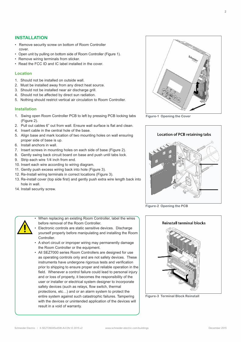
INSTALLATION
• Remove security screw on bottom of Room Controller cover. • Open unit by pulling on bottom side of Room Controller (Figure 1).• Remove wiring terminals from sticker. • Read the FCC ID and IC label installed in the cover.
Location1. Should not be installed on outside wall.2. Must be installed away from any direct heat source.3. Should not be installed near air discharge grill.4. Should not be affected by direct sun radiation.5. Nothing should restrict vertical air circulation to Room Controller.
Installation1. Swing open Room Controller PCB to left by pressing PCB locking tabs
(Figure 2).2. Pulloutcables6”outfromwall.Ensurewallsurfaceisflatandclean.4. Insert cable in the central hole of the base. 5. Align base and mark location of two mounting holes on wall ensuring
proper side of base is up. 6. Install anchors in wall.7. Insert screws in mounting holes on each side of base (Figure 2). 8. Gently swing back circuit board on base and push until tabs lock.9. Strip each wire 1/4 inch from end.10. Insert each wire according to wiring diagram.11. Gently push excess wiring back into hole (Figure 3).12. Re-Install wiring terminals in correct locations (Figure 3).13.Re-installcover(topsidefirst)andgentlypushextrawirelengthbackinto
hole in wall.14. Install security screw.
• When replacing an existing Room Controller, label the wires before removal of the Room Controller.
• Electronic controls are static sensitive devices. Discharge yourself properly before manipulating and installing the Room Controller.
• A short circuit or improper wiring may permanently damage the Room Controller or the equipment.
• All SEZ7000 series Room Controllers are designed for use as operating controls only and are not safety devices. These instrumentshaveundergonerigoroustestsandverificationprior to shipping to ensure proper and reliable operation in the field.Wheneveracontrolfailurecouldleadtopersonalinjuryand or loss of property, it becomes the responsibility of the user or installer or electrical system designer to incorporate safetydevices(suchasrelays,flowswitch,thermalprotections, etc…) and or an alarm system to protect the entire system against such catastrophic failures. Tampering with the devices or unintended application of the devices will result in a void of warranty.
Figure-1 Opening the Cover
Figure-2 Opening the PCB
Figure-3 Terminal Block Reinstall
3
Schneider Electric | II-SEZ7260X5x45W-A4.EN.12.2015.v2 www.schneider-electric.com/buildings December 2015
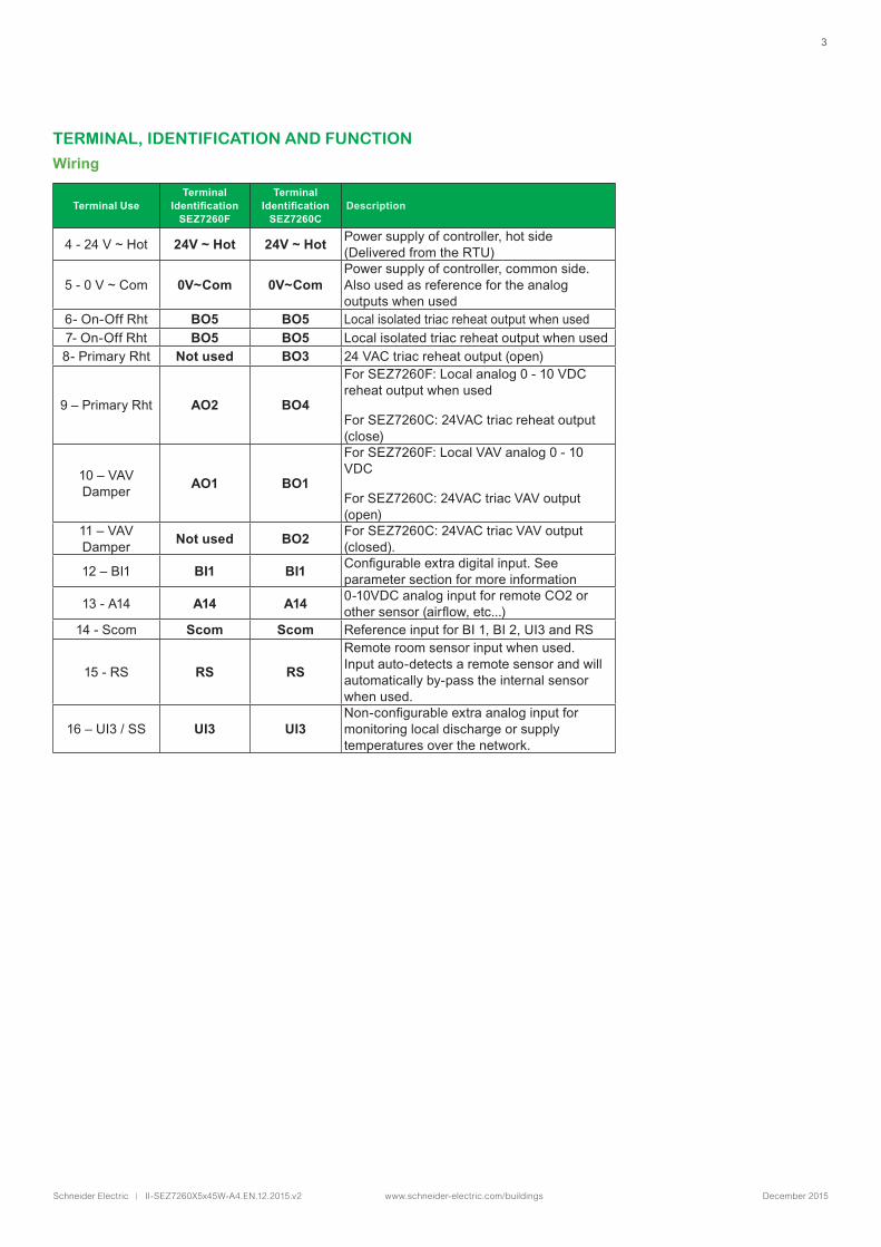
TERMINAL, IDENTIFICATION AND FUNCTION
Wiring
Main Outputs Wiring
Terminal UseTerminal
Identification SEZ7260F
Terminal Identification
SEZ7260CDescription
4 - 24 V ~ Hot 24V ~ Hot 24V ~ Hot Power supply of controller, hot side (Delivered from the RTU)
5 - 0 V ~ Com 0V~Com 0V~ComPower supply of controller, common side. Also used as reference for the analog outputs when used
6- On-Off Rht BO5 BO5 Local isolated triac reheat output when used7- On-Off Rht BO5 BO5 Local isolated triac reheat output when used8- Primary Rht Not used BO3 24 VAC triac reheat output (open)
9 – Primary Rht AO2 BO4
For SEZ7260F: Local analog 0 - 10 VDC reheat output when used
For SEZ7260C: 24VAC triac reheat output (close)
10 – VAV Damper AO1 BO1
For SEZ7260F: Local VAV analog 0 - 10 VDC
For SEZ7260C: 24VAC triac VAV output (open)
11 – VAV Damper Not used BO2 For SEZ7260C: 24VAC triac VAV output
(closed).
12 – BI1 BI1 BI1 Configurableextradigitalinput.Seeparameter section for more information
13 - A14 A14 A14 0-10VDC analog input for remote CO2 or othersensor(airflow,etc...)
14 - Scom Scom Scom Reference input for BI 1, BI 2, UI3 and RS
15 - RS RS RS
Remote room sensor input when used. Input auto-detects a remote sensor and will automatically by-pass the internal sensor when used.
16 – UI3 / SS UI3 UI3Non-configurableextraanaloginputformonitoring local discharge or supply temperatures over the network.
4
Schneider Electric | II-SEZ7260X5x45W-A4.EN.12.2015.v2 www.schneider-electric.com/buildings December 2015
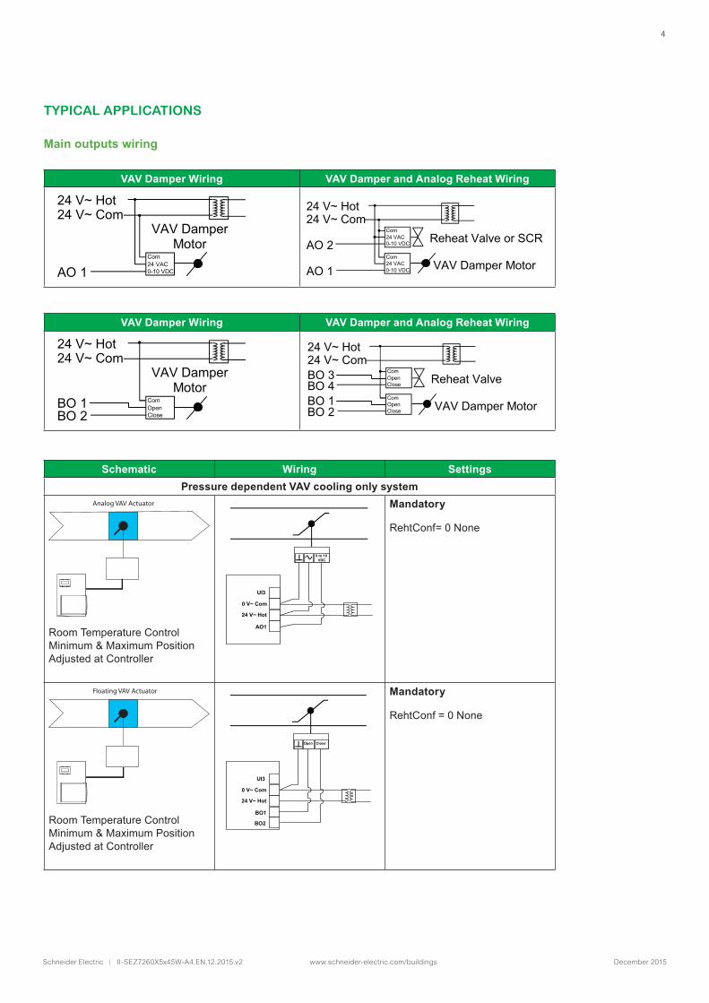
TYPICAL APPLICATIONS
Main outputs wiring
VAV Damper Wiring VAV Damper and Analog Reheat Wiring
VAV Damper Motor
Com 24 VAC 0-10 VDC
24 V~ Hot 24 V~ Com
AO 1
24 V~ Hot 24 V~ Com AO 2
AO 1
Com 24 VAC 0-10 VDC Reheat Valve or SCR
VAV Damper Motor Com 24 VAC 0-10 VDC
VAV Damper Wiring VAV Damper and Analog Reheat Wiring
VAV Damper Motor
Com Open Close
24 V~ Hot 24 V~ Com
BO 2 BO 1
24 V~ Hot 24 V~ Com BO 4
BO 2
Com Open Close Reheat Valve
VAV Damper Motor Com Open Close
BO 3
BO 1
Schematic Wiring SettingsPressure dependent VAV cooling only system
Analog VAV Actuator
Room Temperature ControlMinimum & Maximum PositionAdjustedatController
0 to 10 VDC
UI3
0 V~ Com 24 V~ Hot
AO1
Mandatory
RehtConf= 0 None
Floating VAV Actuator
Room Temperature ControlMinimum & Maximum PositionAdjustedatController
Close
UI3
0 V~ Com 24 V~ Hot
BO1 BO2
Open
Mandatory
RehtConf = 0 None
5
Schneider Electric | II-SEZ7260X5x45W-A4.EN.12.2015.v2 www.schneider-electric.com/buildings December 2015
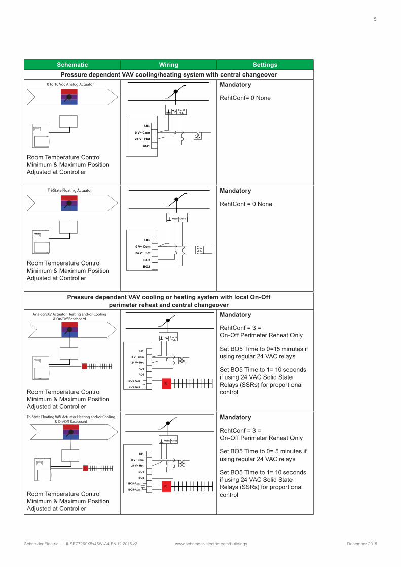
Schematic Wiring SettingsPressure dependent VAV cooling/heating system with central changeover
0 to 10 Vdc Analog Actuator
Room Temperature ControlMinimum & Maximum PositionAdjustedatController
0 to 10 VDC
UI3
0 V~ Com 24 V~ Hot
AO1
Mandatory
RehtConf= 0 None
Tri-State Floating Actuator
Room Temperature ControlMinimum & Maximum PositionAdjustedatController
Close
UI3
0 V~ Com 24 V~ Hot
BO1 BO2
Open
Mandatory
RehtConf = 0 None
Pressure dependent VAV cooling or heating system with local On-Off perimeter reheat and central changeover
Analog VAV Actuator Heating and/or Cooling& On/O Baseboard
Room Temperature ControlMinimum & Maximum PositionAdjustedatController
0 to 10 VDC
UI3
0 V~ Com 24 V~ Hot
AO1
BO5-Aux BO5-Aux
AO2
R
Mandatory
RehtConf = 3 = On-Off Perimeter Reheat Only
Set BO5 Time to 0=15 minutes if using regular 24 VAC relays
Set BO5 Time to 1= 10 seconds if using 24 VAC Solid State Relays (SSRs) for proportional control
Tri-State Floating VAV Actuator Heating and/or Cooling& On/O Baseboard
Room Temperature ControlMinimum & Maximum PositionAdjustedatController
UI3
0 V~ Com 24 V~ Hot
BO1
BO5-Aux BO5-Aux
BO2
R
Close Open
Mandatory
RehtConf = 3 = On-Off Perimeter Reheat Only
Set BO5 Time to 0= 5 minutes if using regular 24 VAC relays
Set BO5 Time to 1= 10 seconds if using 24 VAC Solid State Relays (SSRs) for proportional control
6
Schneider Electric | II-SEZ7260X5x45W-A4.EN.12.2015.v2 www.schneider-electric.com/buildings December 2015
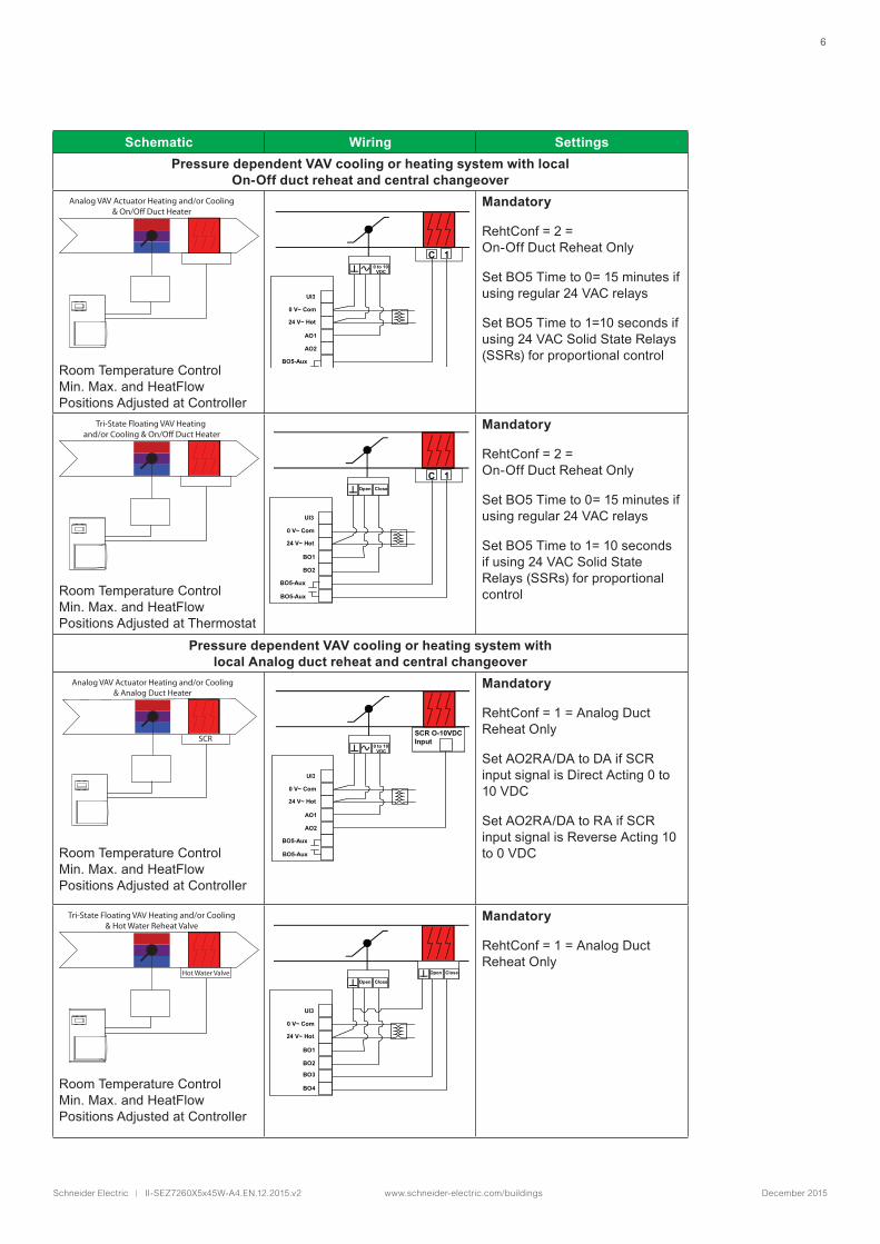
Schematic Wiring SettingsPressure dependent VAV cooling or heating system with local
On-Off duct reheat and central changeoverAnalog VAV Actuator Heating and/or Cooling
& On/O Duct Heater
Room Temperature ControlMin. Max. and HeatFlow PositionsAdjustedatController
1 C 0 to 10
VDC
UI3
0 V~ Com 24 V~ Hot
AO1
BO5-Aux BO5-Aux
AO2
Mandatory
RehtConf = 2 = On-Off Duct Reheat Only
Set BO5 Time to 0= 15 minutes if using regular 24 VAC relays
Set BO5 Time to 1=10 seconds if using 24 VAC Solid State Relays (SSRs) for proportional control
Tri-State Floating VAV Heating and/or Cooling & On/O Duct Heater
Room Temperature ControlMin. Max. and HeatFlow PositionsAdjustedatThermostat
UI3
0 V~ Com 24 V~ Hot
BO1
BO5-Aux BO5-Aux
BO2
Close Open 1 C
Mandatory
RehtConf = 2 = On-Off Duct Reheat Only
Set BO5 Time to 0= 15 minutes if using regular 24 VAC relays
Set BO5 Time to 1= 10 seconds if using 24 VAC Solid State Relays (SSRs) for proportional control
Pressure dependent VAV cooling or heating system with local Analog duct reheat and central changeover
Analog VAV Actuator Heating and/or Cooling& Analog Duct Heater
SCR
Room Temperature ControlMin. Max. and HeatFlow PositionsAdjustedatController
SCR O-10VDC Input
0 to 10 VDC
UI3
0 V~ Com 24 V~ Hot
AO1
BO5-Aux BO5-Aux
AO2
Mandatory
RehtConf = 1 = Analog Duct Reheat Only
Set AO2RA/DA to DA if SCR input signal is Direct Acting 0 to 10 VDC
Set AO2RA/DA to RA if SCR input signal is Reverse Acting 10 to 0 VDC
Tri-State Floating VAV Heating and/or Cooling& Hot Water Reheat Valve
Hot Water Valve
Room Temperature ControlMin. Max. and HeatFlow PositionsAdjustedatController
UI3
0 V~ Com 24 V~ Hot
BO1 BO2
Close Open Close Open
BO3 BO4
Mandatory
RehtConf = 1 = Analog Duct Reheat Only
7
Schneider Electric | II-SEZ7260X5x45W-A4.EN.12.2015.v2 www.schneider-electric.com/buildings December 2015
ºC ºF Kohm
-40 -40 324.3197
-39 -38 303.6427
-38 -36 284.4189
-37 -35 266.5373
-36 -33 249.8958
-35 -31 234.4009
-34 -29 219.9666
-33 -27 206.5140
-32 -26 193.9703
-31 -24 182.2686
-30 -22 171.3474
-29 -20 161.1499
-28 -18 151.6239
-27 -17 142.7211
-26 -15 134.3971
-25 -13 126.6109
-24 -11 119.3244
-23 -9 112.5028
-22 -8 106.1135
-21 -6 100.1268
ºC ºF Kohm
-20 -4 94.5149
-19 -2 89.2521
-18 0 84.3147
-17 1 79.6808
-16 3 75.3299
-15 5 71.2430
-14 7 67.4028
-13 9 63.7928
-12 10 60.3980
-11 12 57.2044
-10 14 54.1988
-9 16 51.3692
-8 18 48.7042
-7 19 46.1933
-6 21 43.8268
-5 23 41.5956
-4 25 39.4921
-3 27 37.5056
-2 28 35.6316
-1 30 33.8622
ºC ºF Kohm
0 32 32.1910
1 34 30.6120
2 36 29.1197
3 37 27.7088
4 39 26.3744
5 41 25.1119
6 43 23.9172
7 45 22.7861
8 46 21.7151
9 48 20.7004
10 50 19.7390
11 52 18.8277
12 54 17.9636
13 55 17.1440
14 57 16.3665
15 59 15.6286
16 61 14.9280
17 63 14.2629
18 64 13.6310
19 66 13.0307
ºC ºF Kohm
20 68 12.4601
21 70 11.9177
22 72 11.4018
23 73 10.9112
24 75 10.4443
25 77 10.0000
26 79 9.5754
27 81 9.1711
28 82 8.7860
29 84 8.4190
30 86 8.0694
31 88 7.7360
32 90 7.4182
33 91 7.1150
34 93 6.8259
35 95 6.5499
36 97 6.2866
37 99 6.0351
38 100 5.7950
39 102 5.5657
ºC ºF Kohm
40 104 5.3467
41 106 5.1373
42 108 4.9373
43 109 4.7460
44 111 4.5631
45 113 4.3881
46 115 4.2208
47 117 4.0607
48 118 3.9074
49 120 3.7607
50 122 3.6202
51 124 3.4857
52 126 3.3568
53 127 3.2333
54 129 3.1150
55 131 3.0016
56 133 2.8928
57 135 2.7886
58 136 2.6886
59 138 2.5926
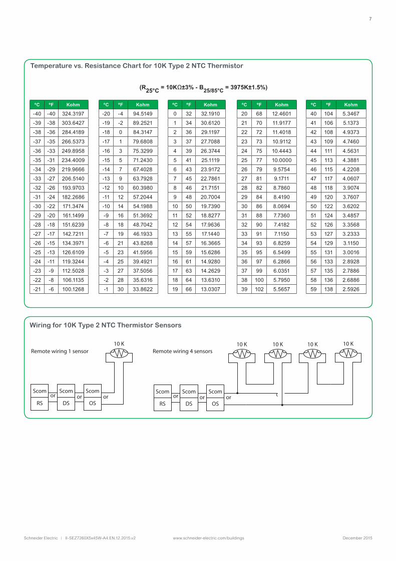
Temperature vs. Resistance Chart for 10K Type 2 NTC Thermistor
(R25°C = 10KΩ±3% - B25/85°C = 3975K±1.5%)
Scom
RS
Remote wiring 1 sensor Remote wiring 4 sensors
orScom
DS
10 K
orScom
OSor
Scom
RSor
Scom
DS
10 K
orScom
OSor
10 K 10 K 10 K
Wiring for 10K Type 2 NTC Thermistor Sensors
8
Schneider Electric | II-SEZ7260X5x45W-A4.EN.12.2015.v2 www.schneider-electric.com/buildings December 2015
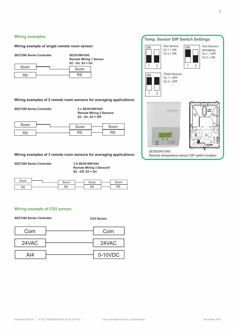
Temp. Sensor DIP Switch Settings
Wiring example of single remote room sensor:
Wiring examples of 2 remote room sensors for averaging applications:
Wiring examples of 3 remote room sensors for averaging applications:
SEZ7260 Series Controller
SEZ7260 Series Controller CO2 Sensor
SEZ7260 Series Controller
SEZ7260 Series Controller
SE3010W1045 Remote Wiring 1 SensorS2 - On, S3 = On
2 x SE3010W1045 Remote Wiring 2 SensorsS2 - On, S3 = Off
3 X SE3010W1045 Remote Wiring 3 SensorSS2 - Off, S3 = On
Scom Scom
RS RS
Com
24VAC
AI4
Com
24VAC
0-10VDC
Scom Scom
RS RSScomRS
Scom Scom
RS RSScomRS
ScomRS
ON
1 2
ON
1 2
One Sensor: S2-1 = ONS2-2 = ON
Two Sensors, averaging:S2-1 = OFFS2-2 = ON
ON
1 2
Three Sensors:S2-1 = OFFS2-2 = OFF
SE3020W1045 Remote temperature sensor DIP switch location
Wiring examples
Wiring example of CO2 sensor:
9
Schneider Electric | II-SEZ7260X5x45W-A4.EN.12.2015.v2 www.schneider-electric.com/buildings December 2015
CONFIGURING AND STATUS DISPLAY INSTRUCTIONS
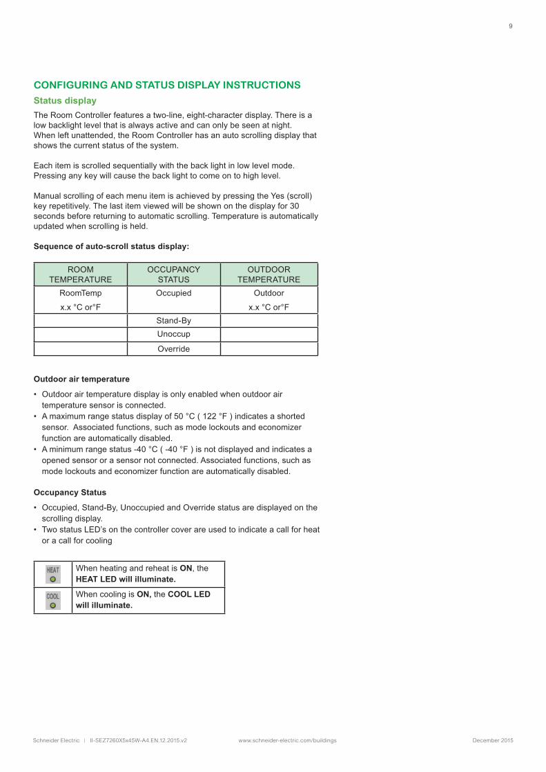
Status displayThe Room Controller features a two-line, eight-character display. There is a low backlight level that is always active and can only be seen at night.When left unattended, the Room Controller has an auto scrolling display that shows the current status of the system.
Each item is scrolled sequentially with the back light in low level mode. Pressing any key will cause the back light to come on to high level.
Manual scrolling of each menu item is achieved by pressing the Yes (scroll) key repetitively. The last item viewed will be shown on the display for 30 seconds before returning to automatic scrolling. Temperature is automatically updated when scrolling is held.
Sequence of auto-scroll status display:
ROOM TEMPERATURE
OCCUPANCY STATUS
OUTDOOR TEMPERATURE
RoomTemp
x.x °C or°F
Occupied Outdoor
x.x °C or°FStand-ByUnoccup
Override
Outdoor air temperature
• Outdoor air temperature display is only enabled when outdoor air temperature sensor is connected.
• A maximum range status display of 50 °C ( 122 °F ) indicates a shorted sensor. Associated functions, such as mode lockouts and economizer function are automatically disabled.
• A minimum range status -40 °C ( -40 °F ) is not displayed and indicates a opened sensor or a sensor not connected. Associated functions, such as mode lockouts and economizer function are automatically disabled.
Occupancy Status
• Occupied, Stand-By, Unoccupied and Override status are displayed on the scrolling display.
• Two status LED’s on the controller cover are used to indicate a call for heat or a call for cooling
When heating and reheat is ON, the HEAT LED will illuminate.
When cooling is ON, the COOL LED will illuminate.
10
Schneider Electric | II-SEZ7260X5x45W-A4.EN.12.2015.v2 www.schneider-electric.com/buildings December 2015
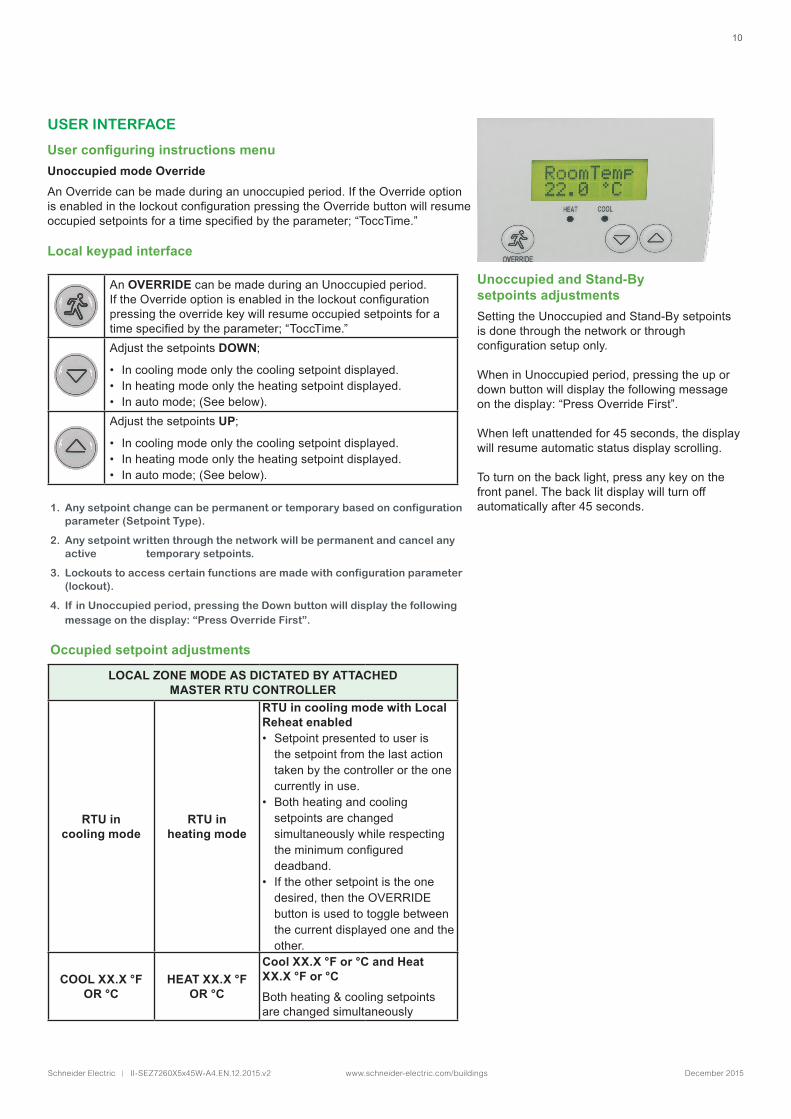
USER INTERFACE
User configuring instructions menuUnoccupied mode OverrideAn Override can be made during an unoccupied period. If the Override option isenabledinthelockoutconfigurationpressingtheOverridebuttonwillresumeoccupiedsetpointsforatimespecifiedbytheparameter;“ToccTime.”
Local keypad interface
1. Any setpoint change can be permanent or temporary based on configuration parameter (Setpoint Type).
2. Any setpoint written through the network will be permanent and cancel any active temporary setpoints.
3. Lockouts to access certain functions are made with configuration parameter (lockout).
4. If in Unoccupied period, pressing the Down button will display the following message on the display: “Press Override First”.
Occupied setpoint adjustments
LOCAL ZONE MODE AS DICTATED BY ATTACHED MASTER RTU CONTROLLER
RTU in cooling mode
RTU in heating mode
RTU in cooling mode with Local Reheat enabled• Setpoint presented to user is
the setpoint from the last action taken by the controller or the one currently in use.
• Both heating and cooling setpoints are changed simultaneously while respecting theminimumconfigureddeadband.
• If the other setpoint is the one desired, then the OVERRIDE button is used to toggle between the current displayed one and the other.
COOL XX.X °F OR °C
HEAT XX.X °F OR °C
Cool XX.X °F or °C and Heat XX.X °F or °CBoth heating & cooling setpoints are changed simultaneously
An OVERRIDE can be made during an Unoccupied period. IftheOverrideoptionisenabledinthelockoutconfigurationpressing the override key will resume occupied setpoints for a timespecifiedbytheparameter;“ToccTime.”AdjustthesetpointsDOWN;
• In cooling mode only the cooling setpoint displayed.• In heating mode only the heating setpoint displayed.• Inautomode;(Seebelow).AdjustthesetpointsUP;
• In cooling mode only the cooling setpoint displayed.• In heating mode only the heating setpoint displayed.• Inautomode;(Seebelow).
Unoccupied and Stand-By setpoints adjustmentsSetting the Unoccupied and Stand-By setpoints is done through the network or through configurationsetuponly.
When in Unoccupied period, pressing the up or down button will display the following message onthedisplay:“PressOverrideFirst”.
When left unattended for 45 seconds, the display will resume automatic status display scrolling.
To turn on the back light, press any key on the front panel. The back lit display will turn off automatically after 45 seconds.

11
Schneider Electric | II-SEZ7260X5x45W-A4.EN.12.2015.v2 www.schneider-electric.com/buildings December 2015
Technical SupportFor any issues with SmartStruxure Solution or SmartStruxure Lite, contact Schneider ElectricTechnical Support according to your region.
AMERICAS
• +1-(978)-975-9508: Andover, MA, USA, 8:30am - 5:00pm (EST)
• +1-(800)-830-1274: Carrollton, TX, USA, 8:00am - 5:00pm (CST)
• +1-(888)-444-1311: Rockford, IL, USA, 8:00am - 5:00pm (CST)
EUROPE
• +44-1628-741-147: London, England, UK, 8:00am - 4:30pm (GMT)
• +46-40-38-69-00: Malmö, Sweden, 8:00am - 4:15pm (CET/CEST)
ASIA PACIFIC
Contact Technical Support at https://ecobuilding.schneider-electric.com/support