Embed Size (px)
Citation preview


Sewage Pumping Station Code of Australia
WSA 04—2005
Second Edition Version 2.1
Previous edition WSA 04—2001

CONTENTS PREFACE 6
INTRODUCTION 9
PART 0: GLOSSARY OF TERMS AND ABBREVIATIONS
I Glossary of Terms 12
II Abbreviations 19
III Referenced Documents 23
IV Other References 30
PART 1: PLANNING AND DESIGN
Contents 36
1 General 45
2 Concept Design 53
3 General Design 62
4 Materials Design 70
5 Pumping Station Design 71
6 Pumping System 88
7 Power System 94
8 Control and Telemetry System 99
9 Wet-Well Pipework 115
10 Pressure Main 121
11 Structural Design 137
12 Supporting Systems 148
13 Health and Safety 150
14 Design Review 152
15 Design Documentation and Drawings 153
Appendix A Typical Precomissioning Checklist 157
Appendix B Commissioning Schedule 161
Appendix C AC Voltage Mitigation of Steel Pipelines 162
Appendix D Computer Program for Pressure Main Sizing 163
Appendix E Detailed Design Checklist 167
PART 2: PRODUCTS AND MATERIALS
Contents 174
16 Products and Materials Overview 176
Appendix F Quality Assurance of Products 187
PART 3: CONSTRUCTION
Contents 194

17 General 202
18 Quality 205
19 General Construction 208
20 Products, Materials and Equipment 215
21 Electrical Works 222
22 Telemetry System 235
23 Odour Control System 237
24 Mechanical Installation of Pumps, Valves and Fittings 238
25 Metalwork 240
26 Access Road and Hardstand Areas 242
27 Retaining Walls 244
28 Excavation 247
29 Bedding for Pipes, Bends, Wet-Wells and Maintenance Structures 249
30 Pipe Laying and Jointing 250
31 Wet-Wells and Maintenance Holes (MHS) 256
32 Pipe Embedment and Support 258
33 Fill 261
34 Connection to Existing Gravity Sewers 263
35 Restoration 264
36 Acceptance Testing 266
37 Commissioning 277
38 Tolerances on As-Constructed Work 279
39 Work As-Constructed Details 281
Appendix G Ovality Testing of PVC and GRP Gravity Sewers Default Prover
Diameters 282
PART 4: STANDARD DRAWINGS
Contents 284
40 Introduction 285
41 Listing of Standard Drawings 286
STANDARD DRAWINGS

Sewage Pumping Station
Code of Australia
WSA 04—2005
Part 1: Planning and Design
Second Edition Version 2.1

WSA 04—2005-2.1
COPYRIGHT
36
CONTENTS
PREFACE
1 GENERAL 1.1 SCOPE 1.2 PLANNING
1.2.1 General 1.2.2 Pumping alternatives
1.3 SEWAGE PUMPING STATIONS 1.3.1 Pumping philosophy
1.4 PURPOSE AND APPLICATION 1.5 PLANNING AND DESIGN RESPONSIBILITIES AND INTERFACES
1.5.1 General 1.5.2 Planning responsibilities 1.5.3 Design responsibilities 1.5.4 Consultation with other parties
1.6 SEWER SYSTEM DESIGN APPROACH 1.6.1 Overall objective 1.6.2 System design life 1.6.3 Objectives of design 1.6.4 Design output
2 CONCEPT DESIGN 2.1 LIFE CYCLE CONSIDERATIONS 2.2 FUNCTIONALITY 2.3 MAINTAINABILITY 2.4 RELIABILITY 2.5 DUE DILIGENCE REQUIREMENTS 2.6 MATERIALS DESIGN 2.7 STAGING 2.8 SEPTICITY CONTROL
2.8.1 General 2.8.2 Detention time
2.9 ODOUR CONTROL 2.10 NOISE CONTROL 2.11 SERVICES 2.12 ACCESS 2.13 SECURITY 2.14 SIGNAGE 2.15 SUPPORTING SYSTEMS 2.16 HEALTH AND SAFETY 2.17 COMMISSIONING PLAN
2.17.1 General 2.17.2 Pre-commissioning 2.17.3 Commissioning
3 GENERAL DESIGN 3.1 GENERAL 3.2 DESIGN TOLERANCES 3.3 LEVELS 3.4 UNFORESEEN GROUND CONDITIONS 3.5 IMPACT OF CONSEQUENTIAL DAMAGE 3.6 ENVIRONMENTAL CONSIDERATIONS

WSA 04—2005-2.1
COPYRIGHT
37
3.6.1 General 3.6.2 Urban salinity 3.6.3 Effect on vegetation 3.6.4 Contaminated sites 3.6.5 Tidal zones
3.7 EASEMENTS 3.8 CROSSINGS
3.8.1 General 3.8.2 Creeks and drainage reserves 3.8.3 Major roads
3.9 FUTURE MAINTENANCE 3.10 AC VOLTAGE MITIGATION OF METALLIC PIPELINES 3.11 OBSTRUCTIONS AND CLEARANCES
3.11.1 General 3.11.2 Surface obstructions 3.11.3 Clearance from structures 3.11.4 Underground obstructions and services
3.11.4.1 General 3.11.4.2 Clearance requirements
3.11.5 Crossing services 3.11.6 Deviation of pressure mains around structures
3.12 DISUSED OR REDUNDANT ITEMS 3.13 SEWAGE QUALITY
3.13.1 Septicity 3.13.2 Sewage quality/Trade waste management
4 MATERIALS DESIGN 4.1 GENERAL 4.2 CORROSION PROTECTION
4.2.1 Protective coatings 4.2.2 Concrete surfaces 4.2.3 Metallic materials 4.2.4 Miscellaneous items 4.2.5 Corrosion protection against aggressive environments 4.2.6 Cathodic protection 4.2.7 Stray current corrosion 4.2.8 Protection against contaminated ground
5 PUMPING STATION DESIGN 5.1 INTRODUCTION 5.2 SITE SELECTION, LOCATION AND LAYOUT
5.2.1 Site selection 5.2.2 Right of occupancy and access 5.2.3 Location and layout 5.2.4 Site area 5.2.5 Site layout and access 5.2.6 Landscaping
5.3 INLET MH 5.3.1 Location 5.3.2 Design 5.3.3 Pumping station wet-well isolating valve
5.4 WET-WELL DESIGN 5.4.1 General 5.4.2 Sizing
WSA 04—2005-2.1
COPYRIGHT
38
5.4.3 Pumping control volume and pump starts 5.4.4 Control levels 5.4.5 Detention time 5.4.6 Benching 5.4.7 Washers
5.5 WET-WELL VENTILATION 5.5.1 Natural ventilation 5.5.2 Forced ventilation 5.5.3 Educt vent shaft
5.6 OVERFLOW CONTAINMENT 5.6.1 General 5.6.2 Emergency storage
5.6.2.1 General 5.6.2.2 Configurations 5.6.2.3 Design 5.6.2.4 Access and cover arrangements 5.6.2.5 Type of construction
5.6.3 Future storage provisions 5.6.4 Emergency relief system
5.7 LADDERS AND PLATFORMS 5.8 WET-WELL ACCESS COVERS 5.9 SAFETY SYSTEMS 5.10 GRIT COLLECTION 5.11 SCREENS 5.12 MIXERS
6 PUMPING SYSTEM 6.1 STAGING 6.2 HYDRAULIC DESIGN 6.3 PUMP EQUIPMENT 6.4 PUMP SELECTION 6.5 TRIPLE-PUMP PUMPING STATIONS 6.6 SUBMERSIBLE PUMPS
6.6.1 General 6.6.2 Impeller selection 6.6.3 Motor selection 6.6.4 Standard discharge connection 6.6.5 Junction boxes 6.6.6 Pumpset lifting equipment
6.7 ANCILLARY EQUIPMENT 6.7.1 Flushing valves
6.8 PUMP STARTERS AND VARIABLE SPEED DRIVES 6.8.1 General 6.8.2 Single and double speed starters 6.8.3 Soft starters 6.8.4 Variable speed drives
6.9 HARMONICS AND RADIO FREQUENCY INTERFERENCE 6.10 EMERGENCY STOP
7 POWER SYSTEM 7.1 GENERAL 7.2 POWER SUPPLIES
7.2.1 General 7.2.2 Security of supply
WSA 04—2005-2.1
COPYRIGHT
39
7.2.3 Primary supply 7.2.4 Duplicate supply 7.2.5 Emergency power 7.2.6 On-site generator 7.2.7 Mobile generator 7.2.8 High voltage/Low voltage switching 7.2.9 Power factor correction
7.3 POWER AND CONTROL CUBICLE 7.3.1 Design 7.3.2 Low voltage switchboards
7.3.2.1 Standards 7.3.2.2 Construction 7.3.2.3 Rated diversity factor 7.3.2.4 Degree of protection 7.3.2.5 Rated insulation and operating voltages 7.3.2.6 Creepage distances 7.3.2.7 Rated impulse withstand voltage 7.3.2.8 Rated short-time current 7.3.2.9 Internal arcing fault protection
7.3.3 Meter requirements 7.3.4 Lighting
8 CONTROL AND TELEMETRY SYSTEM 8.1 GENERAL 8.2 OPERATING LEVELS AND SETTINGS 8.3 PUMPING CONTROL
8.3.1 Control design 8.3.2 Control switches 8.3.3 Control systems 8.3.4 Emergency back–up control 8.3.5 Pump starts and interlocks
8.4 ALARMS 8.4.1 General 8.4.2 Locally displayed alarms 8.4.3 Remote alarms
8.5 ALARM, STATUS MONITORING AND CONTROL TELEMETRY 8.5.1 General design principles 8.5.2 Reliability 8.5.3 Alarm creation function 8.5.4 Status monitoring function 8.5.5 Control function
8.6 TELEMETRY HARDWARE 8.6.1 General 8.6.2 Software 8.6.3 Inputs and outputs 8.6.4 Telemetry communications 8.6.5 Communication validation
8.7 OPERATING LEVELS AND DEFAULT SETTINGS 8.7.1 General 8.7.2 Cut-in and cut-out levels 8.7.3 Alarm levels
8.8 EQUIPMENT AND DEVICES 8.8.1 General 8.8.2 Flow measurement 8.8.3 Flowmeter cabling
WSA 04—2005-2.1
COPYRIGHT
40
8.8.4 Suction safety switch 8.8.5 Level sensors 8.8.6 Float-switch 8.8.7 Site access monitoring 8.8.8 Protection devices
8.8.8.1 Fuse and fuse-links 8.8.8.2 Moulded-case circuit-breakers 8.8.8.3 Miniature circuit-breakers 8.8.8.4 Residual current devices 8.8.8.5 Thermal-overload relays 8.8.8.6 Electronic motor protection relays 8.8.8.7 Thermistor and RTD motor protection devices
8.8.9 Switching devices 8.8.9.1 Switches 8.8.9.2 Selector switches
8.8.10 Contactors 8.8.11 Push-buttons 8.8.12 Emergency stop-buttons 8.8.13 Time-switches 8.8.14 Control devices
8.8.14.1 Control relays 8.8.14.2 Time-delay relays and timers
8.8.15 ELV control transformers 8.8.16 Current transformers
8.9 INSTRUMENTATION (DISPLAYS) 8.10 WIRE NUMBERING CONVENTION 8.11 SYSTEMS INCORPORATING PROGRAMMABLE CONTROLLER / TELEMETRY RTU
8.11.1 Digital inputs and outputs 8.11.2 Analog inputs and outputs 8.11.3 Address codes for communication link devices
8.12 SYSTEMS INCORPORATING RELAY CONTROL 8.12.1 General 8.12.2 Loop tag definition guidelines
9 WET-WELL PIPEWORK 9.1 PUMP DISCHARGE PIPEWORK
9.1.1 General 9.1.2 Sizing 9.1.3 Type
9.2 VALVE APPLICATIONS 9.2.1 Isolating valves 9.2.2 Non-return valves 9.2.3 Scour/Emergency by-pass connection 9.2.4 Sewage air-release valves
9.3 VALVE CHAMBER 9.3.1 General 9.3.2 Design 9.3.3 Dismantling joints 9.3.4 Pipework support 9.3.5 Pressure main tappings 9.3.6 Access covers
9.4 EMERGENCY PUMPING ARRANGEMENTS 9.4.1 Condition monitoring and maintenance

WSA 04—2005-2.1
COPYRIGHT
41
10 PRESSURE MAIN 10.1 DESIGN
10.1.1 General 10.2 LOCATION OF PRESSURE MAINS
10.2.1 General 10.2.2 Road reserves 10.2.3 Railway reserves 10.2.4 Alignment 10.2.5 Changes in direction 10.2.6 Easements
10.3 HYDRAULIC DESIGN 10.3.1 Total mean head 10.3.2 Mean static head 10.3.3 Friction head loss 10.3.4 Fitting head loss 10.3.5 Velocity in pressure mains 10.3.6 Sizing of pressure mains
10.4 DESIGN PRESSURES 10.4.1 General 10.4.2 Maximum design pressure 10.4.3 Surge 10.4.4 Maximum design pressure range
10.5 SELECTION OF PIPE AND FITTINGS PRESSURE CLASS 10.5.1 General 10.5.2 Maximum allowable operating pressure 10.5.3 Maximum cyclic pressure range - Thermoplastics pipes and fittings 10.5.4 Minimum pressure class 10.5.5 Other considerations
10.6 PLASTICS PIPES 10.6.1 Temperature de-rating of plastic pipes and fittings 10.6.2 Fatigue design for thermoplastics pipes 10.6.3 Fatigue design for thermoplastic fittings 10.6.4 Fatigue design for thermosetting pipes and fittings 10.6.5 Combined effects of fatigue and temperature
10.7 METALLIC PIPES AND FITTINGS 10.8 PIPELINE MATERIALS 10.9 PRESSURE MAIN VALVES
10.9.1 General 10.9.2 Isolating valves 10.9.3 Gas release valves 10.9.4 Non-return valves 10.9.5 Scours
10.10 ODOUR AND SEPTICITY CONTROL 10.11 RECEIVING SYSTEM
10.11.1 General 10.11.2 Discharge MHs
11 STRUCTURAL DESIGN 11.1 DIFFICULT GROUND CONDITIONS
11.1.1 Foundation design and ground water control 11.1.2 Geotechnical assessment
11.2 STRUCTURES 11.2.1 Design loads and forces 11.2.2 Concrete structures

WSA 04—2005-2.1
COPYRIGHT
42
11.2.2.1 General 11.2.2.2 Concrete strength 11.2.2.3 Minimum cover 11.2.2.4 Crack control requirement for serviceability 11.2.2.5 Areas to be designed as liquid retaining surfaces
11.2.3 Steel structures 11.2.4 Foundations 11.2.5 Pumping station walls 11.2.6 Base slab 11.2.7 Top slab 11.2.8 Emergency storage structures
11.3 PRESSURE MAINS 11.3.1 General 11.3.2 Products and materials 11.3.3 Structural computations 11.3.4 External forces
11.3.4.1 General 11.3.4.2 Pipe cover 11.3.4.3 Trench design 11.3.4.4 Pipe embedment
11.3.5 Specific geotechnical considerations 11.3.5.1 Pressure mains in engineered and/or controlled fill 11.3.5.2 Pressure mains in non-engineered fill 11.3.5.3 Filling along route of pressure main 11.3.5.4 Mine subsidence 11.3.5.5 Slip areas 11.3.5.6 Water-charged ground
11.3.6 Above ground crossings 11.3.7 Bulkheads and trenchstops 11.3.8 Trenchless technology 11.3.9 Pressure main anchorage
11.3.9.1 General 11.3.9.2 Thrust blocks 11.3.9.3 Anchor blocks
11.3.10 Restrained elastomeric seal joint pressure mains 11.3.11 Restraint requirements for special situations
11.3.11.1 Above ground pressure mains with unrestrained flexible joints 11.3.11.2 Steel mains with welded joints, buried 11.3.11.3 Steel mains with welded joints, above ground 11.3.11.4 Ductile iron or steel mains with flanged joints
12 SUPPORTING SYSTEMS 12.1 SERVICES
12.1.1 General 12.1.2 Water 12.1.3 Telephone/Telemetry lines 12.1.4 General lighting and power 12.1.5 Drainage 12.1.6 Water closet
12.2 MATERIALS HANDLING 12.2.1 Lifting equipment 12.2.2 Handling and storage of hazardous material
12.3 SECURITY 12.4 FIRE CONTROL

WSA 04—2005-2.1
COPYRIGHT
43
13 HEALTH AND SAFETY 13.1 GENERAL 13.2 HAZARDS 13.3 HEALTH AND SAFETY
13.3.1 General 13.3.2 Working at heights
13.4 CONFINED SPACES
14 DESIGN REVIEW
15 DESIGN DOCUMENTATION AND DRAWINGS 15.1 DOCUMENTATION 15.2 DESIGN DRAWINGS
15.2.1 General 15.2.2 Real property information 15.2.3 Pumping station and emergency storage 15.2.4 Structures 15.2.5 Pressure mains and sewers 15.2.6 Longitudinal sections (profiles) 15.2.7 Title block notation and standard notes 15.2.8 Other 15.2.9 Electrical and telemetry
15.3 DRAFTING STANDARDS 15.3.1 General 15.3.2 Scale 15.3.3 Recording of as-constructed information
APPENDIX A TYPICAL PRECOMMISSIONING CHECKLIST
APPENDIX B TYPICAL COMMISSIONING SCHEDULE
APPENDIX C AC VOLTAGE MITIGATION OF STEEL PIPELINES C1 INTRODUCTION C2 INDUCTIVE COUPLING HAZARD C3 CONDUCTIVE COUPLING HAZARD C4 CAPACITIVE COUPLING HAZARD C5 MITIGATION
APPENDIX D PRESSURE MAIN CALCULATOR D1 PRESSURE MAIN CALCULATOR D2 NOMENCLATURE D3 PRINCIPLES AND CRITERIA
D3.1 Design flows D3.2 Detention time D3.3 Minimum internal diameter of pressure main D3.4 Maximum internal diameter of pressure main D3.5 Minimum pumping rate D3.6 Maximum pumping rate D3.7 Pump control volume (cut-in / cut-out volume) and pump starts
D4 INSTRUCTIONS D4.1 Data entry D4.2 Internal diameter of pressure main D4.3 Pumping rate and detention time D4.4 Wet-well control volume / actual starts / detention time

WSA 04—2005-2.1
COPYRIGHT
44
D4.5 Printing D4.6 New calculation D4.7 Reset
APPENDIX E DETAILED DESIGN CHECKLIST TABLES TABLE 1.1 TYPICAL ASSET DESIGN LIFE TABLE 3.1 CLEARANCES BETWEEN PRESSURE MAINS AND UNDERGROUND SERVICES TABLE 5.1 DEFAULT CONTROL LEVELS TABLE 8.1 DEFAULT ALARM LEVELS TABLE 8.2 TYPICAL LOCAL AND REMOTE ALARMS TABLE 8.3 TYPICAL REMOTE MONITORED CONDITIONS TABLE 10.1 PRESSURE DE-RATING FACTORS FOR PLASTIC PIPES AT ELEVATED TEMPERATURES TABLE 10.2 FATIGUE DE-RATING FACTORS FOR THERMOPLASTIC PIPES TABLE 10.3 SCOUR SIZES TABLE 11.1 REQUIREMENT FOR BULKHEADS
FIGURES FIGURE 1.1 CONCEPT DESIGN FLOWCHART FIGURE 2.1 SPS OVERFLOW RISK REDUCTION DECISION DIAGRAM FIGURE 2.2 TYPICAL PRE-COMMISSIONING AND COMMISSIONG PROCESS FIGURE 2.3 TYPICAL HANDOVER TO WATER AGENCY FIGURE 3.1 DEFLECTION AT JOINTS FIGURE 3.2 DEFLECTION USING SOC-SOC BENDS FIGURE 3.3 DEFLECTION USING SOC-SOC CONNECTORS FIGURE 5.1 TYPICAL EMERGENCY STORAGE – CONFIGURATION 1 FIGURE 5.2 TYPICAL EMERGENCY STORAGE – CONFIGURATION 2 FIGURE 5.3 TYPICAL EMERGENCY STORAGE – CONFIGURATION 3 FIGURE 5.4 TYPICAL EMERGENCY STORAGE – CONFIGURATION 4 FIGURE 8.1 ALARM LEVEL CONTROL SETTINGS FIGURE 10.1 TYPICAL SURGE WAVE FIGURE 10.2 TYPICAL FATIGUE CYCLE
Sewage Pumping Station
Code of Australia
WSA 04—2005
Part 2: Products and Materials
Second Edition
Version 2.1

CONTENTS
16 PRODUCTS AND MATERIALS OVERVIEW 16.1 PURPOSE 16.2 SCOPE 16.3 RESPONSIBILITIES
16.3.1 Water Agency 16.3.2 Designer 16.3.3 Constructor 16.3.4 Purchaser
16.4 PRODUCT AND MATERIAL STANDARDS AND SPECIFICATIONS 16.4.1 Product standards 16.4.2 Purchase specifications 16.4.3 Purchase specifications—Alternatives
16.5 QUALITY ASSURANCE 16.5.1 Default requirement 16.5.2 Additional information on quality assurance 16.5.3 Innovative products and materials
16.6 SELECTION GUIDE FOR PIPELINE SYSTEMS 16.7 ADDITIONAL PRODUCT AND MATERIAL INFORMATION
APPENDIX F F1 GENERAL F2 QUALITY ASSURANCE OPTIONS
F2.1 ISO 9000 quality management system certification F2.2 Product certification
F2.2.1 General F2.2.2 Product certification – Type 1 F2.2.3 Product certification – Type 3 F2.2.4 Product certification – Type 5
F2.3 Supplier’s declaration of conformance F2.4 Second party verification
F3 FACTORS INFLUENCING SELECTION OF QUALITY ASSURANCE OPTIONS F3.1 General factors F3.2 Likelihood of manufacturing non-conformance F3.3 Likelihood of failure of pipeline system from a product non-conformance F3.4 Consequences of failure F3.5 Product specification F3.6 Project magnitude / management F3.7 Innovative products
F4 SELECTING THE QUALITY ASSURANCE OPTION F4.1 General factors F4.2 Product certification
F4.2.1 General F4.2.2 Type 1 F4.2.3 Type 3 F4.2.4 Type 5
F4.3 ISO 9000 quality management system certification F4.4 Supplier’s declaration of conformance F4.5 Second party verification

TABLES
TABLE 16.1 PRINCIPAL PRESSURE MAINS AND COMPONENTS TABLE 16.2 PRECAUTIONS, LIMITATIONS, ADVANTAGES AND DISADVANTAGES
Sewage Pumping Station
Code of Australia
Part 3: Construction
Second Edition Version 2.1
WSA 04—2005-2.1
COPYRIGHT
194
CONTENTS 17 GENERAL
17.1 SCOPE 17.2 INTERPRETATION
18 QUALITY 18.1 QUALITY ASSURANCE
18.1.1 General 18.1.2 Quality management system 18.1.3 Quality system 18.1.4 Project management plan 18.1.5 Inspection and test plans 18.1.6 Quality tests 18.1.7 Quality audits 18.1.8 Traceability 18.1.9 Quality records 18.1.10 Inspection
18.2 PERSONNEL QUALIFICATIONS 19 GENERAL CONSTRUCTION
19.1 GENERAL 19.2 ORDER OF CONSTRUCTION, TESTING AND COMMISSIONING
19.2.1 Pumping stations 19.2.2 Inlet works, emergency storage and ERS 19.2.3 Pressure mains
19.3 CONTRACT INTERFACES 19.4 CUSTOMER FOCUS
19.4.1 General 19.4.2 Resolution of complaints
19.5 PROTECTION OF PEOPLE, PROPERTY AND ENVIRONMENT 19.5.1 Safety of people 19.5.2 Protection of other services 19.5.3 Disused / Redundant sewers and pressure mains 19.5.4 Road reserves or other thoroughfares
19.5.4.1 Treatment of pavements and other surfaces 19.5.4.2 Traffic management 19.5.4.3 Cleanliness of roads, paths, accesses and drainage paths 19.5.4.4 Storage of products, materials and equipment 19.5.4.5 Obstruction of street drainage
19.5.5 Private and public properties 19.5.6 Protection of the environment and heritage areas
19.5.6.1 General 19.5.6.2 Collection and disposal of wastes 19.5.6.3 Protection of adjacent lands and vegetation 19.5.6.4 Control of water pollution 19.5.6.5 Acid sulphate and contaminated soils 19.5.6.6 Control of noise and atmospheric pollution
19.6 AFFECTED PARTY NOTIFICATIONS 19.7 ALTERATION OF EXISTING SERVICES 19.8 SURVEY MARKS

WSA 04—2005-2.1
COPYRIGHT
195
19.9 CONSTRUCTION TOLERANCES 19.10 LATENT CONDITIONS
20 PRODUCTS, MATERIALS AND EQUIPMENT 20.1 AUTHORISED PRODUCTS AND MATERIALS 20.2 REJECTED PRODUCTS AND MATERIALS 20.3 ELECTRICAL EQUIPMENT 20.4 PUMPS 20.5 TRANSPORTATION, HANDLING AND STORAGE OF PRODUCTS AND MATERIALS 20.6 DELIVERY AND STORAGE OF ELECTRICAL EQUIPMENT 20.7 DELIVERY INSPECTION OF PRODUCTS AND MATERIALS 20.8 FASTENERS 20.9 WORKS INSPECTION AND TESTING
20.9.1 Switchboards 20.9.2 Pumps 20.9.3 Motors
20.10 CONCRETE WORKS 20.10.1 Delivery 20.10.2 Transportation of concrete 20.10.3 Formwork 20.10.4 Reinforcement 20.10.5 Placement
20.10.5.1 General 20.10.5.2 Placement in water
20.10.6 Slump 20.10.7 Compaction 20.10.8 Stripping 20.10.9 Curing 20.10.10 Repair of blemishes
20.11 SUPPLY OF WATER TO THE WORKS 20.12 ON-SITE STOCKPILES
21 ELECTRICAL WORKS 21.1 COMPLIANCE WITH AUTHORITIES, STATUTES, REGULATIONS AND STANDARDS 21.2 SCOPE OF WORK 21.3 SUPPLY AUTHORITY REQUIREMENTS AND METERING 21.4 CONSUMER MAINS
21.4.1 Point of supply 21.4.2 Cable size 21.4.3 Maximum demand 21.4.4 Calculations to be submitted 21.4.5 Mains in reserves 21.4.6 Mains requirements 21.4.7 Lead-in pole and overhead mains construction
21.4.7.1 Lead-in pole 21.4.7.2 Poles 21.4.7.3 Installation of poles 21.4.7.4 Aerial cables
21.4.8 Underground cable installation 21.4.8.1 General

WSA 04—2005-2.1
COPYRIGHT
196
21.4.8.2 Location 21.4.8.3 Excavation and bedding 21.4.8.4 Underground cable marking 21.4.8.5 Cable installation on poles 21.4.8.6 Road crossings
21.5 EARTHING 21.5.1 General 21.5.2 Earth circuits 21.5.3 Labelling
21.6 SWITCHBOARD INSTALLATION 21.6.1 General 21.6.2 Equipment mounting 21.6.3 Thermal derating of equipment 21.6.4 Labelling
21.6.4.1 General 21.6.4.2 Incoming mains and pump and motor detail labels 21.6.4.3 Main labels 21.6.4.4 Cubicle labels 21.6.4.5 Danger notices 21.6.4.6 Asset and equipment number labels
21.7 CIRCUITS 21.7.1 Main circuits 21.7.2 Control circuit wiring
21.8 CABLING 21.8.1 General 21.8.2 Conduits 21.8.3 Cable protection 21.8.4 Cable trays 21.8.5 Junction boxes
21.9 INSTALLATION OF PUMP CABLES 21.9.1 Numbering of pumps 21.9.2 Installation
21.10 INSTALLATION OF LEVEL SENSORS 21.10.1 General 21.10.2 Wet-well level sensor probes
21.11 TERMINATIONS 21.11.1 General 21.11.2 Glands 21.11.3 Mains and pump terminations
21.12 PAINTING 21.12.1 General 21.12.2 Paint materials 21.12.3 Surface preparation 21.12.4 Painting and finish
21.13 INSTALLATION IN VALVE PITS 21.13.1 General 21.13.2 Cables
21.14 NOTIFICATION OF ELECTRICAL WORK 22 TELEMETRY SYSTEM

WSA 04—2005-2.1
COPYRIGHT
197
22.1 COMPLIANCE WITH AUTHORITIES, STATUTES, REGULATIONS AND STANDARDS 22.2 SCOPE OF WORK 22.3 HARDWARE INSTALLATION 22.4 PLC PROGRAMMING 22.5 SCADA DATABASE CONFIGURATION
23 ODOUR CONTROL SYSTEM 24 MECHANICAL INSTALLATION OF PUMPS, VALVES AND FITTINGS
24.1 GENERAL 24.2 FLANGED JOINTS 24.3 INSTALLATION OF PUMPING UNITS
24.3.1 General 24.3.2 Machinery alignment 24.3.3 Unit numbers 24.3.4 Test tapping points
24.4 GAUGES AND RECORDERS 24.4.1 Pressure gauges 24.4.2 Pressure recorder
25 METALWORK 25.1 STEELWORK 25.2 ALUMINIUM ALLOY COMPONENTS 25.3 STAINLESS STEEL COMPONENTS 25.4 FASTENERS
26 ACCESS ROAD AND HARDSTAND AREAS 26.1 GENERAL 26.2 SUBGRADE 26.3 BASECOURSE 26.4 SPRAYED BITUMINOUS SEALING 26.5 ASPHALTIC CONCRETE 26.6 TIMBER GUARDRAIL
27 RETAINING WALLS 27.1 RETAINING WALLS - TIMBER CANTILEVER
27.1.1 General 27.1.2 Handrails
27.2 RETAINING WALLS - CONCRETE - CRIB WALL 27.2.1 General 27.2.2 Foundations 27.2.3 Cribfill and backfill 27.2.4 Drainage 27.2.5 Handrails
28 EXCAVATION 28.1 SAFETY 28.2 LIMITS OF EXCAVATION 28.3 EXCAVATION ACROSS IMPROVED SURFACES 28.4 EXCAVATION IN ROOT ZONES 28.5 BLASTING 28.6 SUPPORT OF EXCAVATIONS 28.7 DRAINAGE AND DEWATERING

WSA 04—2005-2.1
COPYRIGHT
198
28.8 FOUNDATIONS AND FOUNDATION STABILISATION 28.9 SURPLUS EXCAVATED MATERIAL
29 BEDDING FOR PIPES, BENDS, WET-WELLS AND MAINTENANCE STRUCTURES 29.1 TRENCH FLOOR PREPARATION 29.2 BEDDING MATERIALS 29.3 PLACEMENT OF BEDDING 29.4 SPECIAL PIPE SUPPORT FOR NON-SUPPORTIVE SOILS 29.5 BEDDING FOR PIPES, VALVES AND FITTINGS 29.6 BEDDING FOR CONCRETE STRUCTURES 29.7 BEDDING FOR MAINTENANCE SHAFTS AND VARIABLE BENDS
30 PIPE LAYING AND JOINTING 30.1 INSTALLATION OF PIPES
30.1.1 General 30.1.2 Cleaning, inspection and joint preparation 30.1.3 Polyethylene 30.1.4 Laying
30.2 HORIZONTAL AND VERTICAL DEFLECTION OF GRAVITY SEWERS AND PRESSURE MAINS
30.2.1 General 30.2.2 Methods of deflection
30.3 HORIZONTAL AND VERTICAL SEPARATION OF CROSSING PIPELINES 30.4 FLOTATION CONTROL 30.5 THRUST AND ANCHOR BLOCKS AND RESTRAINED JOINTS FOR PRESSURE MAINS 30.6 MARKING TAPES
30.6.1 Non-detectable marking tape 30.6.2 Detectable marking tape
30.7 VALVES AND SURFACE FITTINGS 30.7.1 Installation 30.7.2 Scours for pressure mains
30.8 BORED PIPES UNDER ROADS, DRIVEWAYS AND ELSEWHERE 30.9 BRIDGE CROSSINGS 30.10 TRENCH STOPS FOR PRESSURE MAINS 30.11 BULKHEADS FOR PRESSURE MAINS 30.12 CORROSION PROTECTION OF CAST IRON FOR PRESSURE MAINS 30.13 AQUEDUCTS 30.14 LOCATION MARKERS 30.15 FLANGED JOINTS 30.16 WELDING OF STEEL PRESSURE MAINS
30.16.1 General 30.16.2 Field welding of flanges
31 WET-WELLS AND MAINTENANCE HOLES (MHS) 31.1 GENERAL 31.2 WET-WELL AND MH BASES 31.3 TRENCH DRAINAGE AROUND WET-WELLS AND MHS 31.4 PRECAST CONCRETE SYSTEMS 31.5 CAST IN-SITU CONCRETE WET-WELLS AND MHS 31.6 BENCHING AND CHANNELS 31.7 INTERNAL COATING OF CONCRETE WET-WELLS AND MHS

WSA 04—2005-2.1
COPYRIGHT
199
31.8 COVERS 31.9 CONNECTIONS TO WET-WELLS AND MHS 31.10 MH DROPS
32 PIPE EMBEDMENT AND SUPPORT 32.1 GENERAL 32.2 EMBEDMENT MATERIALS 32.3 COMPACTION OF EMBEDMENT
32.3.1 General 32.3.2 Methods 32.3.3 Compaction trials/Pre-qualification of embedment compaction method
32.3.3.1 General 32.3.3.2 Test method 32.3.3.3 Interpretation and applicability
32.3.4 Compaction control 32.4 SPECIAL BEDDING AND EMBEDMENTS/GEOTEXTILE SURROUND AND PILLOW 32.5 REMOVAL OF TRENCH SUPPORTS 32.6 CONCRETE EMBEDMENT AND ENCASEMENT
33 FILL 33.1 TRENCH FILL 33.2 GENERAL 33.3 MATERIAL REQUIREMENTS 33.4 COMPACTION OF TRENCH FILL 33.5 EMBANKMENT FILL 33.6 DRIVES AND TUNNEL FILL
34 CONNECTION TO EXISTING GRAVITY SEWERS 35 RESTORATION
35.1 GENERAL 35.2 PAVEMENTS 35.3 LAWNS 35.4 GRASSED AREAS 35.5 BUSHLAND 35.6 PROVISION FOR SETTLEMENT 35.7 MAINTENANCE OF RESTORED SURFACES
36 ACCEPTANCE TESTING 36.1 PIPELINES 36.2 VISUAL EXTERNAL INSPECTION 36.3 COMPACTION TESTING
36.3.1 General 36.3.2 Minimum compaction 36.3.3 Embedment compaction testing
36.3.3.1 Applicable pipe sizes 36.3.3.2 Frequency and location of embedment tests 36.3.3.3 Retesting
36.3.4 Trench fill compaction testing 36.3.4.1 Trafficable test zone 36.3.4.2 Non-trafficable test zone 36.3.4.3 Test method 36.3.4.4 Frequency and location of tests

WSA 04—2005-2.1
COPYRIGHT
200
36.3.4.5 Retesting 36.3.5 Other fill compaction testing
36.3.5.1 General 36.3.5.2 Trafficable test zone 36.3.5.3 Non-trafficable test zone 36.3.5.4 Frequency and location of tests 36.3.5.5 Retesting
36.4 AIR PRESSURE AND VACUUM TESTING OF GRAVITY SEWERS 36.4.1 General 36.4.2 Air testing methods for sewers
36.4.2.1 Vacuum testing 36.4.2.2 Low pressure air testing
36.4.3 Testing of concrete emergency storage and maintenance structures 36.4.3.1 General 36.4.3.2 Test method
36.5 HYDROSTATIC PRESSURE TESTING OF PRESSURE MAINS 36.5.1 General 36.5.2 System test pressure 36.5.3 Maximum allowable loss 36.5.4 Test procedure 36.5.5 Satisfactory pressure test 36.5.6 Failure of test
36.6 INFILTRATION TESTING 36.7 DEFLECTION (OVALITY) TESTING OF FLEXIBLE GRAVITY SEWERS
36.7.1 General 36.7.2 Ovality proving tools 36.7.3 Flexible sewers ≤DN 300
36.8 CCTV INSPECTION 36.9 ELECTRICAL WORKS
37 COMMISSIONING 37.1 GENERAL 37.2 PUMPING STATION
37.2.1 Requirements 37.2.2 Pre-commissioning 37.2.3 Commissioning 37.2.4 Handover
37.3 ODOUR CONTROL SYSTEM 38 TOLERANCES ON AS-CONSTRUCTED WORK
38.1 HORIZONTAL TOLERANCES 38.1.1 Sewers, mains, valves, in-line structures, pumping stations, roads
38.2 VERTICAL TOLERANCES 38.2.1 Sewers, pressure mains, structures, pumping stations, roads 38.2.2 Grade
38.3 VERTICALITY (“PLUMB”) 38.4 TOLERANCES ON FINISHED SURFACE STRUCTURES AND FITTINGS 38.5 CAST IN-SITU CONCRETE STRUCTURES AND SLABS
39 WORK AS-CONSTRUCTED DETAILS 39.1 GENERAL 39.2 ELECTRICAL WORKS

WSA 04—2005-2.1
COPYRIGHT
201
39.2.1 Electrical Contractors Installation Drawings 39.2.2 Principal Supplied Installation Drawings and Equipment Schedules
APPENDIX G OVALITY TESTING OF PVC AND GRP GRAVITY SEWERS DEFAULT PROVER DIAMETERS
G1 GENERAL G2 DEFAULT PROVER DIAMETERS
TABLES TABLE 21.1 CONTROL CIRCUIT WIRING INSULATION COLOUR CODING TABLE 26.1 TIMBER GUARDRAIL DEFAULT CONSTRUCTION DIMENSIONS TABLE 27.1 RETAINING WALL DEFAULT CONSTRUCTION DIMMENSIONS TABLE 27.2 TIMBER HANDRAIL DEFAULT CONSTRUCTION DIMENSIONS TABLE 30.1 METHODS OF ACHIEVING CURVED PIPELINES TABLE 32.1 MAXIMUM PARTICLE SIZE TABLE 36.1 ORDER OF ACCEPTANCE TESTING OF CIVIL ITEMS TABLE 36.2 MINIMUM COMPACTION OF EMBEDMENT AND TRENCH / EMBANKMENT / OTHER FILLS TABLE 36.3 PRESSURE AND VACUUM AIR TESTING ACCEPTANCE TIMES FOR 7 KPA PRESSURE CHANGE TABLE 36.4 CONCRETE MH TESTING FREQUENCY TABLE 36.5 MINIMUM TEST TIMES FOR CONCRETE STRUCTURES TABLE 38.1 SEWER GRADE TOLERANCES TABLE G1 PROVER OUTSIDE DIAMETER FOR PVC AND GRP PIPES TABLE G2 MAXIMUM ALLOWABLE SHORT-TERM PIPE DEFLECTIONS

Sewage Pumping Station
Code of Australia
WSA 04—2005
Part 4: Standard Drawings
Second Edition Version 2.1

WSA 04—2005-2.1
COPYRIGHT
284
CONTENTS
40 INTRODUCTION 40.1 GENERAL 40.2 DRAWING COMMENTARY
41 LISTING OF STANDARD DRAWINGS
WSA 04—2005-2.1
COPYRIGHT
285
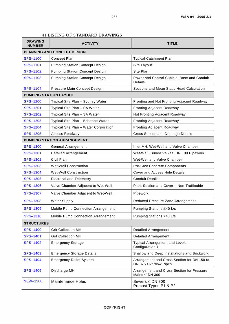
41 LISTING OF STANDARD DRAWINGS DRAWING NUMBER ACTIVITY TITLE
PLANNING AND CONCEPT DESIGN
SPS–1100 Concept Plan Typical Catchment Plan
SPS–1101 Pumping Station Concept Design Site Layout
SPS–1102 Pumping Station Concept Design Site Plan
SPS–1103 Pumping Station Concept Design Power and Control Cubicle, Base and Conduit Details
SPS–1104 Pressure Main Concept Design Sections and Mean Static Head Calculation
PUMPING STATION LAYOUT
SPS–1200 Typical Site Plan – Sydney Water Fronting and Not Fronting Adjacent Roadway
SPS–1201 Typical Site Plan – SA Water Fronting Adjacent Roadway
SPS–1202 Typical Site Plan – SA Water Not Fronting Adjacent Roadway
SPS–1203 Typical Site Plan – Brisbane Water Fronting Adjacent Roadway
SPS–1204 Typical Site Plan – Water Corporation Fronting Adjacent Roadway
SPS–1205 Access Roadway Cross Section and Drainage Details
PUMPING STATION ARRANGEMENT
SPS–1300 General Arrangement Inlet MH, Wet-Well and Valve Chamber
SPS–1301 Detailed Arrangement Wet-Well, Buried Valves, DN 100 Pipework
SPS–1302 Civil Plan Wet-Well and Valve Chamber
SPS–1303 Wet-Well Construction Pre-Cast Concrete Components
SPS–1304 Wet-Well Construction Cover and Access Hole Details
SPS–1305 Electrical and Telemetry Conduit Details
SPS–1306 Valve Chamber Adjacent to Wet-Well Plan, Section and Cover – Non-Trafficable
SPS–1307 Valve Chamber Adjacent to Wet-Well Pipework
SPS–1308 Water Supply Reduced Pressure Zone Arrangement
SPS–1309 Mobile Pump Connection Arrangement Pumping Stations ≤40 L/s
SPS–1310 Mobile Pump Connection Arrangement Pumping Stations >40 L/s
STRUCTURES
SPS–1400 Grit Collection MH Detailed Arrangement
SPS–1401 Grit Collection MH Detailed Arrangement
SPS–1402 Emergency Storage Typical Arrangement and Levels Configuration 1
SPS–1403 Emergency Storage Details Shallow and Deep Installations and Brickwork
SPS–1404 Emergency Relief System Arrangement and Cross Section for DN 150 to DN 375 Overflow Pipes
SPS–1405 Discharge MH Arrangement and Cross Section for Pressure Mains ≤ DN 300
SEW–1300 Maintenance Holes Sewers ≤ DN 300 Precast Types P1 & P2
WSA 04—2005-2.1
COPYRIGHT
286
DRAWING NUMBER ACTIVITY TITLE
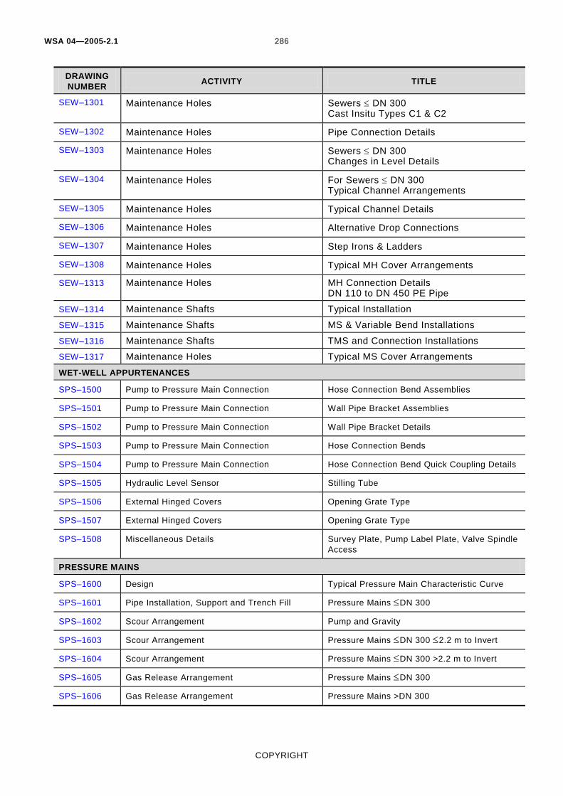
SEW–1301 Maintenance Holes Sewers ≤ DN 300 Cast Insitu Types C1 & C2
SEW–1302 Maintenance Holes Pipe Connection Details
SEW–1303 Maintenance Holes Sewers ≤ DN 300 Changes in Level Details
SEW–1304 Maintenance Holes For Sewers ≤ DN 300 Typical Channel Arrangements
SEW–1305 Maintenance Holes Typical Channel Details
SEW–1306 Maintenance Holes Alternative Drop Connections
SEW–1307 Maintenance Holes Step Irons & Ladders
SEW–1308 Maintenance Holes Typical MH Cover Arrangements
SEW–1313 Maintenance Holes MH Connection Details DN 110 to DN 450 PE Pipe
SEW–1314 Maintenance Shafts Typical Installation
SEW–1315 Maintenance Shafts MS & Variable Bend Installations
SEW–1316 Maintenance Shafts TMS and Connection Installations
SEW–1317 Maintenance Holes Typical MS Cover Arrangements
WET-WELL APPURTENANCES
SPS–1500 Pump to Pressure Main Connection Hose Connection Bend Assemblies
SPS–1501 Pump to Pressure Main Connection Wall Pipe Bracket Assemblies
SPS–1502 Pump to Pressure Main Connection Wall Pipe Bracket Details
SPS–1503 Pump to Pressure Main Connection Hose Connection Bends
SPS–1504 Pump to Pressure Main Connection Hose Connection Bend Quick Coupling Details
SPS–1505 Hydraulic Level Sensor Stilling Tube
SPS–1506 External Hinged Covers Opening Grate Type
SPS–1507 External Hinged Covers Opening Grate Type
SPS–1508 Miscellaneous Details Survey Plate, Pump Label Plate, Valve Spindle Access
PRESSURE MAINS
SPS–1600 Design Typical Pressure Main Characteristic Curve
SPS–1601 Pipe Installation, Support and Trench Fill Pressure Mains ≤DN 300
SPS–1602 Scour Arrangement Pump and Gravity
SPS–1603 Scour Arrangement Pressure Mains ≤DN 300 ≤2.2 m to Invert
SPS–1604 Scour Arrangement Pressure Mains ≤DN 300 >2.2 m to Invert
SPS–1605 Gas Release Arrangement Pressure Mains ≤DN 300
SPS–1606 Gas Release Arrangement Pressure Mains >DN 300

WSA 04—2005-2.1
COPYRIGHT
287
DRAWING NUMBER ACTIVITY TITLE
EMBEDMENT / TRENCHFILL AND SUPPORT SYSTEMS
SEW–1200 Soil Classification Guidelines And Allowable Bearing Pressures for Bulkheads
SEW–1201 Embedment and Trenchfill Typical Arrangements
SEW–1202 Standard Embedment Flexible & Rigid Pipes
SEW–1203 Special Embedment Inadequate Foundations Requiring Over Excavation & Replacement
SEW–1204 Special Embedment Support Utilising Piles
SEW–1206 Trench Drainage Bulkheads & Trenchstop
SEW–1207 Trench Drainage Typical Systems
SEW–1208 Verticals & Near Verticals Exposed & Concealed Methods
WAT–1201 Embedment & Trenchfill Typical Arrangement
WAT–1202 Standard Embedment All Pipe Types
WAT–1203 Special Embedments Inadequate and Poor Foundation
WAT–1204 Special Embedments Concrete, Geotextile and Cement Stabilised Systems
WAT–1205 Thrust Block Details Concrete Blocks
WAT–1206 Thrust Block Details Timber & Recycled Plastic Blocks
WAT–1207 Thrust and Anchor Blocks Gate Valves and Vertical Bends
WAT–1208 Restrained Joint System DN 100 to DN 375 DI Mains
WAT–1209 Trench Drainage Bulkheads and Trenchstop
WAT–1210 Trench Drainage Typical Systems
WAT–1211 Buried Crossings Under Obstructions
WAT–1212 Buried Crossings Major Roadways
WAT–1213 Buried Crossings Railways
WAT–1214 Buried Crossings Bored & Jacked Encasing Pipe Details
SPECIAL CROSSINGS / STRUCTURES ARRANGEMENTS
SEW–1400 Buried Crossings Syphon Arrangement
SEW–1401 Buried Crossings Railways
SEW–1402 Buried Crossings Major Roadways
SEW–1403 Buried Crossings Bored & Jacked Encasing Pipe Details
SEW–1406 Aerial Crossings Bridge Crossing Concepts
SEW–1407 Ventilation Systems Induct Vent
SEW–1408 Ventilation Systems Educt Vent
WSA 04—2005-2.1
COPYRIGHT
288
DRAWING NUMBER ACTIVITY TITLE
INSTALLATION PRACTICES/ STRUCTURES
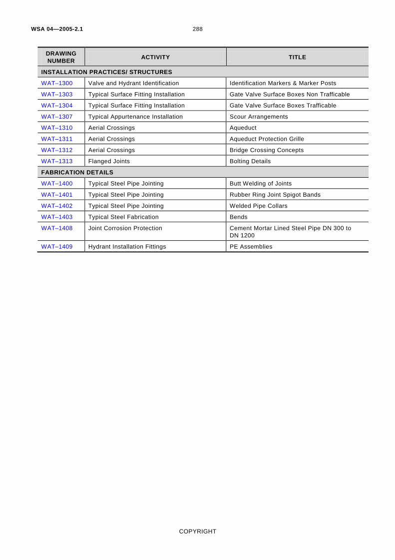
WAT–1300 Valve and Hydrant Identification Identification Markers & Marker Posts
WAT–1303 Typical Surface Fitting Installation Gate Valve Surface Boxes Non Trafficable
WAT–1304 Typical Surface Fitting Installation Gate Valve Surface Boxes Trafficable
WAT–1307 Typical Appurtenance Installation Scour Arrangements
WAT–1310 Aerial Crossings Aqueduct
WAT–1311 Aerial Crossings Aqueduct Protection Grille
WAT–1312 Aerial Crossings Bridge Crossing Concepts
WAT–1313 Flanged Joints Bolting Details
FABRICATION DETAILS
WAT–1400 Typical Steel Pipe Jointing Butt Welding of Joints
WAT–1401 Typical Steel Pipe Jointing Rubber Ring Joint Spigot Bands
WAT–1402 Typical Steel Pipe Jointing Welded Pipe Collars
WAT–1403 Typical Steel Fabrication Bends
WAT–1408 Joint Corrosion Protection Cement Mortar Lined Steel Pipe DN 300 to DN 1200
WAT–1409 Hydrant Installation Fittings PE Assemblies