Embed Size (px)
Citation preview
B723-00-880Issue B Original
Instruction Manual
EXPT Pumping Station
Description Item Number
EXPT Pumping Station B723-00-000
© Edwards Limited 2008. All rights reserved. Page iEdwards and the Edwards logo are trademarks of Edwards Limited.
ContentsB723-00-880 Issue B
Contents
Section Page
1 Introduction ........................................................................................ 1
1.1 Scope and definitions .................................................................................................... 11.2 Description................................................................................................................. 21.2.1 Overview ................................................................................................................... 21.2.2 General description of the EXPT pumping station major components ........................................... 21.2.3 Electrical protection ..................................................................................................... 21.2.4 Accessories ................................................................................................................ 2
2 Technical data ..................................................................................... 5
2.1 General..................................................................................................................... 52.2 Electrical data ............................................................................................................ 62.3 Legislation and standards ............................................................................................... 72.4 Operating and storage data ............................................................................................. 72.5 Fuse ratings................................................................................................................ 72.6 Earth stud.................................................................................................................. 82.7 Electrical connections ................................................................................................... 82.8 Connections ............................................................................................................... 8
3 Installation ....................................................................................... 11
3.1 Safety......................................................................................................................113.2 Unpack and inspect .....................................................................................................113.3 Locate the EXPT pumping station.....................................................................................123.4 Fill the rotary pump with oil...........................................................................................133.5 XDS scroll pump silencer ...............................................................................................133.6 Fit accessories (optional)...............................................................................................133.7 Connect the EXPT pumping station to your vacuum system ......................................................143.8 Connect to your exhaust extraction system.........................................................................143.9 Connect the electrical supply .........................................................................................143.10 Additional earth bonding ...............................................................................................143.11 Configure the EXPT pumping station .................................................................................143.12 Commission the installation............................................................................................163.13 Connecting an active gauge............................................................................................163.14 Connecting the logic interface ........................................................................................163.15 Connecting the serial interface .......................................................................................17
4 Operation ......................................................................................... 19
4.1 Use of the backing pump controls ....................................................................................194.2 Start-up ...................................................................................................................194.3 Shut-down ................................................................................................................19
5 Maintenance...................................................................................... 21
5.1 Safety......................................................................................................................215.2 Maintenance plan........................................................................................................215.3 Inspect the hoses, pipelines and connections.......................................................................225.4 Trouble-shooting.........................................................................................................22
6 Storage and disposal ............................................................................ 23
6.1 Storage ....................................................................................................................236.2 Disposal ...................................................................................................................23
ITR
2146
6
B723-00-880 Issue B
Page ii © Edwards Limited 2008. All rights reserved.Edwards and the Edwards logo are trademarks of Edwards Limited.
Contents
7 Spares and accessories ......................................................................... 25
7.1 Introduction ..............................................................................................................257.2 Spares .....................................................................................................................257.3 Accessories ...............................................................................................................257.3.1 BX bakeout band.........................................................................................................25
Index............................................................................................... 27
Illustrations
Figure Page1 Components of the EXPT pumping station (typical system shown) ............................................... 32 Equipment dimensions (mm) (XDD1 and EXT75DX shown) ......................................................... 93 Position the lifting slings/lifting hooks...............................................................................134 Turbomolecular pump start delay with XDD1 diaphragm pump..................................................15
Tables
Table Page1 EXPT1 pumping station mass............................................................................................ 52 EXPT2 pumping station mass............................................................................................ 53 Electrical data ............................................................................................................ 64 Operating and storage data ............................................................................................. 75 Fuse ratings................................................................................................................ 76 Earth stud.................................................................................................................. 87 Electrical connections ................................................................................................... 88 Connections ............................................................................................................... 89 Checklist of components ...............................................................................................11
Supplementary publications
Publication title Publication numberXDD1 115/230 Diaphragm Pump A746-01-885Turbo Instrument Controller (TIC) D397-10-880EXT75DX Turbomolecular Pump B722-40-880XDS Scroll Pump A726-01-880Low Voltage EXT Compound Molecular Pumps EXT70H / 255H 24 V B722-20-880EXDC Turbomolecular Pump Drive Modules D396-45-880RV Rotary Vane Pumps A652-01-880E2M Rotary Vane Pumps A371-22-880EXPT Pumping Station Instruction Manual (quick guide) B723-00-860CD ROM Instruction Manual B723-00-879
© Edwards Limited 2008. All rights reserved. Page iiiEdwards and the Edwards logo are trademarks of Edwards Limited.
ContentsB723-00-880 Issue B
Associated publications
Publication title Publication numberEXT Pump Accessories B580-65-880

This page has been intentionally left blank.
B723-00-880 Issue B
Page iv © Edwards Limited 2008. All rights reserved.Edwards and the Edwards logo are trademarks of Edwards Limited.
© Edwards Limited 2008. All rights reserved. Page 1Edwards and the Edwards logo are trademarks of Edwards Limited.
IntroductionB723-00-880 Issue B
1 Introduction1.1 Scope and definitions
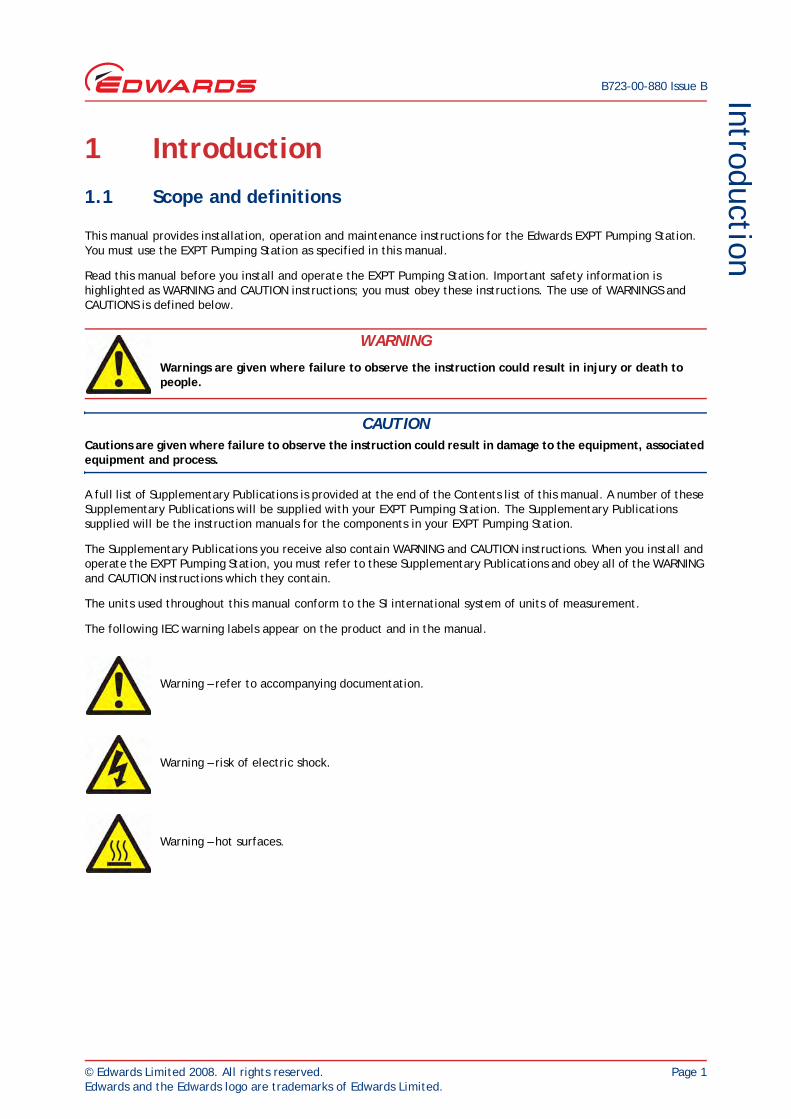
This manual provides installation, operation and maintenance instructions for the Edwards EXPT Pumping Station. You must use the EXPT Pumping Station as specified in this manual.
Read this manual before you install and operate the EXPT Pumping Station. Important safety information is highlighted as WARNING and CAUTION instructions; you must obey these instructions. The use of WARNINGS and CAUTIONS is defined below.
CAUTIONCautions are given where failure to observe the instruction could result in damage to the equipment, associated equipment and process.
A full list of Supplementary Publications is provided at the end of the Contents list of this manual. A number of these Supplementary Publications will be supplied with your EXPT Pumping Station. The Supplementary Publications supplied will be the instruction manuals for the components in your EXPT Pumping Station.
The Supplementary Publications you receive also contain WARNING and CAUTION instructions. When you install and operate the EXPT Pumping Station, you must refer to these Supplementary Publications and obey all of the WARNING and CAUTION instructions which they contain.
The units used throughout this manual conform to the SI international system of units of measurement.
The following IEC warning labels appear on the product and in the manual.
WARNING
Warnings are given where failure to observe the instruction could result in injury or death to people.
Warning – refer to accompanying documentation.
Warning – risk of electric shock.
Warning – hot surfaces.
B723-00-880 Issue B
Page 2 © Edwards Limited 2008. All rights reserved.Edwards and the Edwards logo are trademarks of Edwards Limited.
Introduction
1.2 Description
1.2.1 Overview
The EXPT Pumping Station is a fully automatic pumping system which is suitable for a wide range of applications. The system is capable of utilising an extensive range of standard Edwards backing pumps, turbomolecular pumps and controllers from a single compact unit. The open system configuration allows easy maintenance of the main pumping components.
The function of the controller depends on your system configuration and will control the backing pump and turbomolecular pump plus optional accessories. For systems with turbo and instrument controllers, up to three active gauges may be used using the convenient gauge interface incorporated into the system housing. Both controllers are provided with a large clear graphic display and easy-to-use control interface via a touch sensitive keypad. The system incorporates an RS232/485 interface for control and data monitoring on a remote PC and a logic interface for interface with associated system hardware.
Both systems are base mounted and come in two sizes. The EXPT1 base uses robust rubber feet as standard, castors are optional. The EXPT2 base uses castors as standard to allow ease of transportation.
1.2.2 General description of the EXPT pumping station major components
For the general description of the major components used on the EXPT Pumping Station, click on the appropriate instruction manual reference against each product type.
1.2.3 Electrical protection
The EXPT Pumping Station has a double-pole thermal circuit breaker which provides short circuit protection. The backing pump and TIC Controller both have overload protection.
1.2.4 Accessories
A wide range of standard accessories is available for the major components of the EXPT Pumping Station; refer to Section 7.
Diaphragm pump XDD1 (A746-01-885)Rotary vane pumps E2M0.7 / E2M1.5 (A371-22-880 Section 1.2)
RV3 / RV5 / RV8 / RV12 (A652-01-880 Section 1.2)Turbomolecular pumps EXT70H / EXT255H 24 V (B722-20-880 Section 1.2)
EXT75DX / EXT255DX (B722-40-880 Section 1.2)Scroll pumps XDS5 / XDS10 (A726-01-880 Section 1.2)TIC controller Turbo controller (D397-12-880 Section 1.2)
Turbo instrument controller (D397-22-880 Section 1.2)
© Edwards Limited 2008. All rights reserved. Page 3Edwards and the Edwards logo are trademarks of Edwards Limited.
IntroductionB723-00-880 Issue B
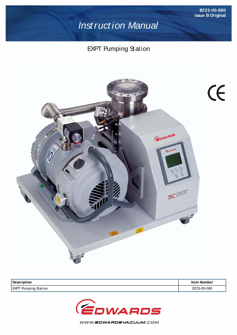
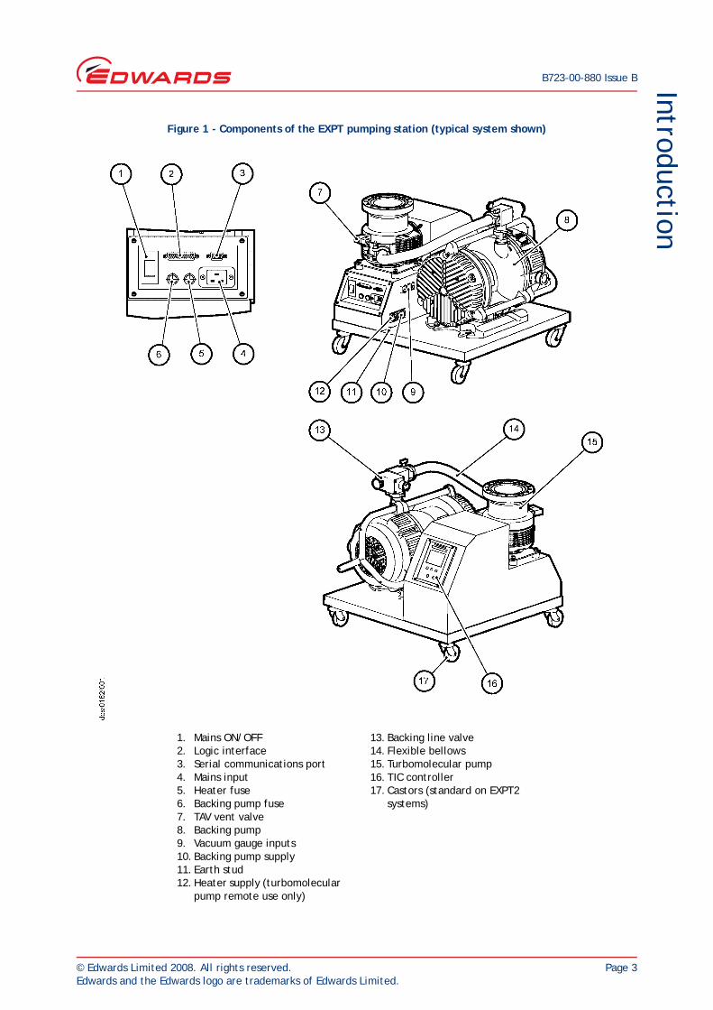
Figure 1 - Components of the EXPT pumping station (typical system shown)
13. Backing line valve14. Flexible bellows15. Turbomolecular pump16. TIC controller17. Castors (standard on EXPT2
systems)
1. Mains ON/OFF2. Logic interface3. Serial communications port4. Mains input5. Heater fuse6. Backing pump fuse7. TAV vent valve8. Backing pump9. Vacuum gauge inputs10. Backing pump supply11. Earth stud12. Heater supply (turbomolecular
pump remote use only)

B723-00-880 Issue B
Page 4 © Edwards Limited 2008. All rights reserved.Edwards and the Edwards logo are trademarks of Edwards Limited.
This page has been intentionally left blank.
© Edwards Limited 2008. All rights reserved. Page 5Edwards and the Edwards logo are trademarks of Edwards Limited.
Technical dataB723-00-880 Issue B
2 Technical dataNote: The operating, storage conditions and performance of the EXPT Pumping Station depends on the major
components fitted to the EXPT Pumping Station; refer to the technical data in the appropriate supplementary publications.
2.1 General
* Measured under ideal conditions and will increase on uneven floor surfaces, slopes etc.
Dimensions Refer to Figure 2Mass Refer to Tables 1 and 2Electrical data Refer to Table 3Degree of protection (to IEC34-5: 1981) IP20Initial force required to push the EXPT pumping station* (for systems with castors)
3.5 kgf max.
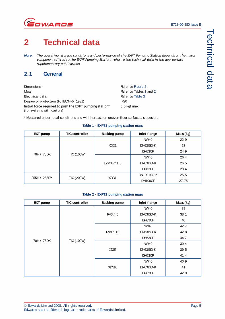
Table 1 - EXPT1 pumping station mass
EXT pump TIC controller Backing pump Inlet flange Mass (kg)
70H / 75DX TIC (100W)
XDD1
NW40 22.9
DN63ISO-K 23
DN63CF 24.9
E2M0.7/1.5
NW40 26.4
DN63ISO-K 26.5
DN63CF 28.4
255H / 255DX TIC (200W) XDD1DN100 ISO-K 25.5
DN100CF 27.75
Table 2 - EXPT2 pumping station mass
EXT pump TIC controller Backing pump Inlet flange Mass (kg)
70H / 75DX TIC (100W)
RV3 / 5
NW40 38
DN63ISO-K 38.1
DN63CF 40
RV8 / 12
NW40 42.7
DN63ISO-K 42.8
DN63CF 44.7
XDS5
NW40 39.4
DN63ISO-K 39.5
DN63CF 41.4
XDS10
NW40 40.9
DN63ISO-K 41
DN63CF 42.9
B723-00-880 Issue B
Page 6 © Edwards Limited 2008. All rights reserved.Edwards and the Edwards logo are trademarks of Edwards Limited.
Technical data
2.2 Electrical data
Table 3 lists the electrical requirements for the different EXPT Pumping Stations.
255H / 255DX TIC (200W)
RV3 / 5DN100 ISO-K 40.6
DN100CF 42.85
RV8 / 12DN100 ISO-K 45.3
DN100CF 47.55
XDS5DN100 ISO-K 42
DN100CF 44.25
XDS10DN100 ISO-K 43.5
DN100CF 45.75
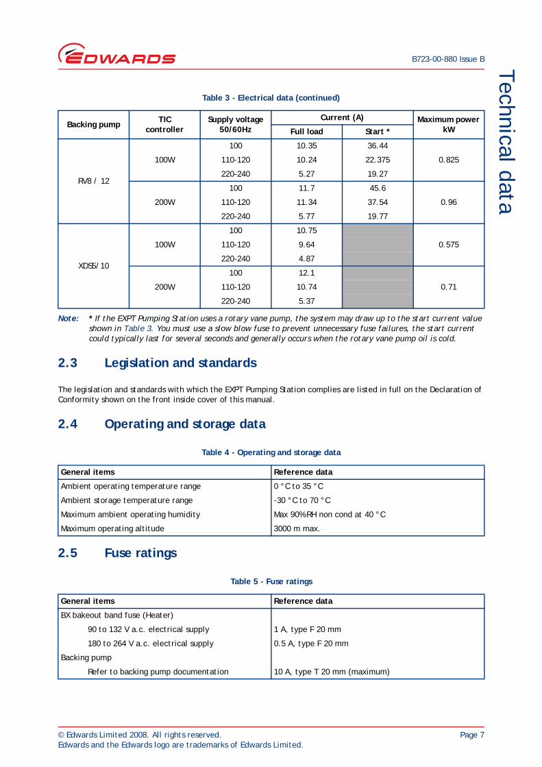
Table 3 - Electrical data
Backing pump TICcontroller
Supply voltage 50/60Hz
Current (A) Maximum power kWFull load Start *
XDD1
100W 0.355100 4.67
110-120 4.04
220-240 2.07
200W
100 6.02
0.49110-120 5.14
220-240 2.57
E2M0.7
100W110-120 4.34 8.14
0.365220-240 2.27 4.07
200W110-120 5.44 9.24
0.5220-240 2.77 4.57
E2M1.5
100W110-120 5.54 14.44
0.435220-240 2.67 6.77
200W110-120 6.64 15.54
0.57220-240 3.17 7.27
RV3 / 5
100W
100 8.15 33.94
0.575110-120 7.04 20.875
220-240 3.67 16.87
200W
100 9.5 43.1
0.71110-120 8.14 35.04
220-240 4.17 17.37
Table 2 - EXPT2 pumping station mass (continued)
EXT pump TIC controller Backing pump Inlet flange Mass (kg)
© Edwards Limited 2008. All rights reserved. Page 7Edwards and the Edwards logo are trademarks of Edwards Limited.
Technical dataB723-00-880 Issue B
Note: * If the EXPT Pumping Station uses a rotary vane pump, the system may draw up to the start current value shown in Table 3. You must use a slow blow fuse to prevent unnecessary fuse failures, the start current could typically last for several seconds and generally occurs when the rotary vane pump oil is cold.
2.3 Legislation and standards
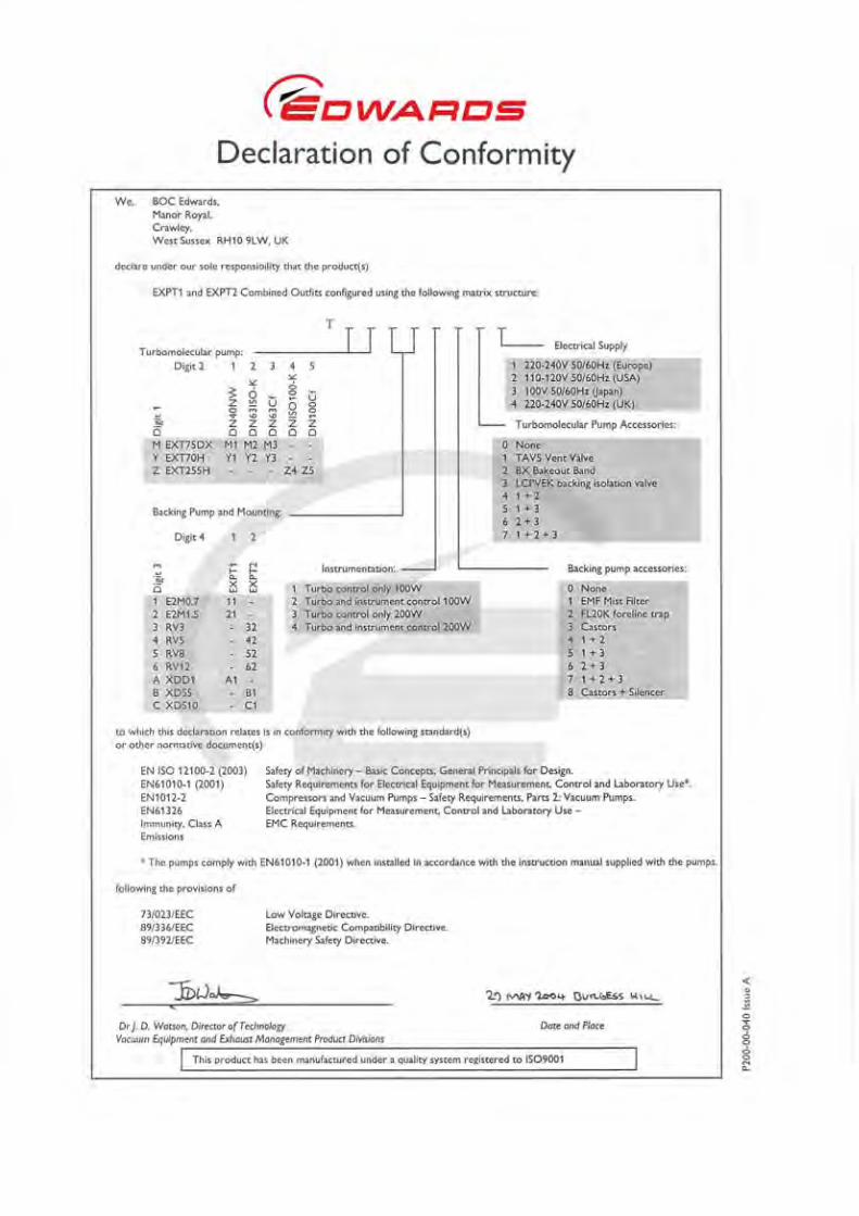
The legislation and standards with which the EXPT Pumping Station complies are listed in full on the Declaration of Conformity shown on the front inside cover of this manual.
2.4 Operating and storage data
2.5 Fuse ratings
RV8 / 12
100W
100 10.35 36.44
0.825110-120 10.24 22.375
220-240 5.27 19.27
200W
100 11.7 45.6
0.96110-120 11.34 37.54
220-240 5.77 19.77
XDS5/10
100W
100 10.75
0.575110-120 9.64
220-240 4.87
200W
100 12.1
0.71110-120 10.74
220-240 5.37
Table 4 - Operating and storage data
General items Reference data
Ambient operating temperature range 0 °C to 35 °C
Ambient storage temperature range -30 °C to 70 °C
Maximum ambient operating humidity Max 90% RH non cond at 40 °C
Maximum operating altitude 3000 m max.
Table 5 - Fuse ratings
General items Reference data
BX bakeout band fuse (Heater)
90 to 132 V a.c. electrical supply 1 A, type F 20 mm
180 to 264 V a.c. electrical supply 0.5 A, type F 20 mm
Backing pump
Refer to backing pump documentation 10 A, type T 20 mm (maximum)
Table 3 - Electrical data (continued)
Backing pump TICcontroller
Supply voltage 50/60Hz
Current (A) Maximum power kWFull load Start *
B723-00-880 Issue B
Page 8 © Edwards Limited 2008. All rights reserved.Edwards and the Edwards logo are trademarks of Edwards Limited.
Technical data
2.6 Earth stud
2.7 Electrical connections
2.8 Connections
Note: The connectors listed in Table 8 offer the same functionality as the connectors on the TIC Controller. Refer to the TIC instruction manual for full details for these connectors.
Table 6 - Earth stud
General items Reference data
Earth stud M5
Table 7 - Electrical connections
General items Reference data
Electrical supply (refer to Figure 1, item 4)
Inlet plug type CEE/IEC 320 (16A)
Backing pump (refer to Figure 1, item 10)
Outlet socket type CEE/IEC 320
Max power 600 W
Bakeout band (refer to Figure 1, item 12)
Outlet socket type CEE/IEC 320
Max power 150 W
Table 8 - Connections
General items Reference data
Active gauge connectors
Connector type FCC/RJ45, 8-way
Power supply 24 V d.c.
Logic interface
Connector type 25-way sub-miniature ‘D’ type socket
Power supply 24 V d.c.
Serial communications
Connector type 9-way sub-miniature ‘D’ type socket
© Edwards Limited 2008. All rights reserved. Page 9Edwards and the Edwards logo are trademarks of Edwards Limited.
Technical dataB723-00-880 Issue B
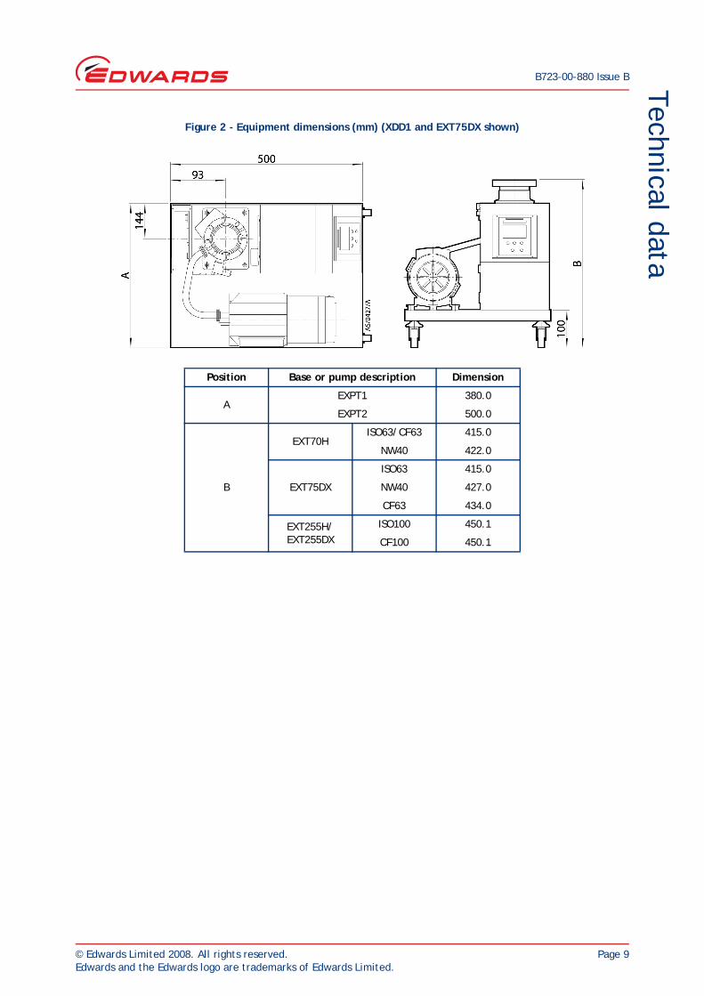
Figure 2 - Equipment dimensions (mm) (XDD1 and EXT75DX shown)
Position Base or pump description Dimension
AEXPT1 380.0
EXPT2 500.0
B
EXT70HISO63/CF63 415.0
NW40 422.0
EXT75DX
ISO63 415.0
NW40 427.0
CF63 434.0
EXT255H/EXT255DX
ISO100 450.1
CF100 450.1

B723-00-880 Issue B
Page 10 © Edwards Limited 2008. All rights reserved.Edwards and the Edwards logo are trademarks of Edwards Limited.
This page has been intentionally left blank.
© Edwards Limited 2008. All rights reserved. Page 11Edwards and the Edwards logo are trademarks of Edwards Limited.
InstallationB723-00-880 Issue B
3 Installation3.1 Safety
When you refer to a manual supplied as a Supplementary Publication, you must obey all of the WARNING and CAUTION instructions in the manual.
A suitably trained and supervised technician must install the EXPT Pumping Station.
Check that all the required parts are available and of the correct type before you start work.
Ensure that the installation technician is familiar with the safety procedures which relate to the products pumped. Wear the appropriate safety-clothing when you come into contact with contaminated components.
Isolate the other components in your system from the electrical supply so that they cannot be operated accidentally.
Do not reuse ‘O’ rings and Co-Seals if they are damaged.
Dispose of components, grease and oil safely (refer to Section 6).
Take care to protect sealing-faces from damage.
Leak-test the system after installation and seal any leaks found.
3.2 Unpack and inspect
Remove the outer cover and all packing materials, remove the protective covers from the inlet and outlet ports, inspect the system for any damage. If the EXPT Pumping Station is damaged, notify your supplier and the carrier in writing within three days; state your order number and invoice number. Retain all packing materials for inspection. Do not use the EXPT Pumping Station if it is damaged. Check that your package contains the items listed in Table 9. If any item is missing, notify your supplier within three days.
If the EXPT Pumping Station is not to be used immediately, replace the protective covers. Store the EXPT Pumping Station in suitable conditions as described in Section 6.1.
WARNING
Obey the safety instructions given below and take note of appropriate precautions. If you do not, you can cause injury to people and damage to equipment.
Table 9 - Checklist of components
Qty Description Check (✓)
1 EXPT Pumping Station ❏
1 Instruction Manual Package ❏
1 Logic Interface Interlock D-Connector ❏
1 TMP Flange Inlet Seal ❏
1 Rotary Pump Oil (RV/E2M pumps only) ❏
1 XDS Silencer (optional on systems with XDS pumps) ❏
B723-00-880 Issue B
Page 12 © Edwards Limited 2008. All rights reserved.Edwards and the Edwards logo are trademarks of Edwards Limited.
Installation
3.3 Locate the EXPT pumping station
CAUTIONWhen lifting the EXPT Pumping Station, do not attempt to support the mass of the system from the backing pump.
CAUTIONWhen lifting the EXPT Pumping Station, always use slings with sufficient length to prevent damage of the system components.
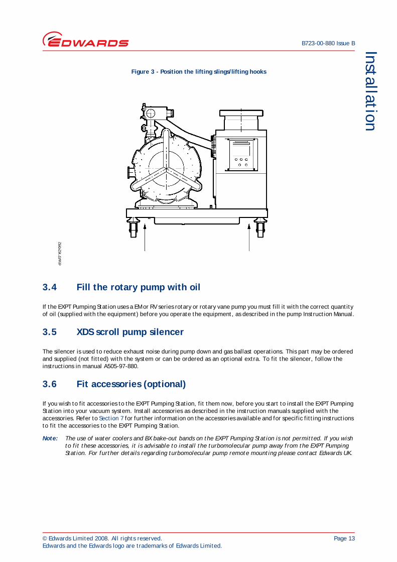
Before attempting to lift the EXPT Pumping Station, move the system (on its pallet) close to the operating position. Ensure that you provide a firm level base before removing the system from its pallet. It is advisable to always use mechanical lifting equipment when moving the heavier EXPT2 systems. Use slings around the base of the system from front to back, make sure each sling is routed between the castors or feet and the base guides to prevent slippage. Alternatively use straps with lifting hooks. Refer to Figure 3 which shows where to locate the slings or lifting hooks.
CAUTIONWhen locating the EXPT Pumping Station, care should be taken not to restrict the ventilation grid located under the base of the system. Failing to observe this may result in over heating of the controller and the turbomolecular pump.
WARNING
Heavy objects can cause muscle strain or back injury. It is advisable to use suitable lifting equipment when moving the EXPT Pumping Station.
WARNING
(Applicable for systems with base castors) For your safety, both front castors must be locked when the system is in operation. If you do not and the turbomolecular pump seizes, movement of the system may damage equipment and injure people.
© Edwards Limited 2008. All rights reserved. Page 13Edwards and the Edwards logo are trademarks of Edwards Limited.
InstallationB723-00-880 Issue B
Figure 3 - Position the lifting slings/lifting hooks
3.4 Fill the rotary pump with oil
If the EXPT Pumping Station uses a EM or RV series rotary or rotary vane pump you must fill it with the correct quantity of oil (supplied with the equipment) before you operate the equipment, as described in the pump Instruction Manual.
3.5 XDS scroll pump silencer
The silencer is used to reduce exhaust noise during pump down and gas ballast operations. This part may be ordered and supplied (not fitted) with the system or can be ordered as an optional extra. To fit the silencer, follow the instructions in manual A505-97-880.
3.6 Fit accessories (optional)
If you wish to fit accessories to the EXPT Pumping Station, fit them now, before you start to install the EXPT Pumping Station into your vacuum system. Install accessories as described in the instruction manuals supplied with the accessories. Refer to Section 7 for further information on the accessories available and for specific fitting instructions to fit the accessories to the EXPT Pumping Station.
Note: The use of water coolers and BX bake-out bands on the EXPT Pumping Station is not permitted. If you wish to fit these accessories, it is advisable to install the turbomolecular pump away from the EXPT Pumping Station. For further details regarding turbomolecular pump remote mounting please contact Edwards UK.
B723-00-880 Issue B
Page 14 © Edwards Limited 2008. All rights reserved.Edwards and the Edwards logo are trademarks of Edwards Limited.
Installation
3.7 Connect the EXPT pumping station to your vacuum system
Note: If the vacuum system is to be supported by the EXPT Pumping Station, the mass of the vacuum system must not be greater than the maximum mass which can be supported by the turbomolecular pump (refer to the EXT Pump Instruction Manual). Use the co-seal or copper gasket (supplied with the equipment) with a suitable clamp to secure to the vacuum system. Alternatively you may wish to use a pipeline to connect the vacuum system to the inlet of the turbomolecular pump. Refer to the EXT Pump Instruction Manual for further details.
3.8 Connect to your exhaust extraction system
Note: For further information, refer to the instruction manual which corresponds to the backing pump fitted to your EXPT Pumping Station.
3.9 Connect the electrical supply
Check that your electrical supply is suitable for this equipment. Refer to Table 3 for the electrical requirements for this equipment. The EXPT Pumping Station is supplied with an electrical cable which includes a moulded IEC connector fitted at one end, the other end of the cable will be fitted with a moulded plug suitable for connection to the local electrical supply.
3.10 Additional earth bonding
The electrical supply cable normally provides protective earthing for electrical safety. If this is not the case, or if additional earth bonding is required, the earth stud located on the base at the rear of the EXPT Pumping Station should be connected to your vacuum system.
3.11 Configure the EXPT pumping station
As supplied, the TIC Controller has been reconfigured for the TIC Pumping Station to suit most vacuum applications and will:
When the TIC System ON is selected:
Switch on both the backing pump and the turbomolecular pump *.
Close the TAV vent valve.
Open the backing valve.
WARNING
If you install your vacuum system directly onto the EXPT Pumping Station, the centre of gravity of the mass must be above and within 300 mm of the centre line.
WARNING
Ensure that the electrical installation of the EXPT Pumping Station conforms with your local and national safety requirements. It must be connected to a suitably fused and protected electrical supply and a suitable earth point.
WARNING
Ensure the mains cord is routed so as not to cause a trip hazard.
© Edwards Limited 2008. All rights reserved. Page 15Edwards and the Edwards logo are trademarks of Edwards Limited.
InstallationB723-00-880 Issue B
When the TIC System OFF is selected:
Switch off both the backing pump and the turbomolecular pump.
Close the backing valve.
EXDC pump controllers:
Open the TAV vent valve fully after the turbomolecular pump has slowed to 50% of its rotational speed.
DX pump controllers:
Open the TAV vent valve (controlled venting) from 100–50% rotational speed, and then open fully from 50% of full rotational speed.
Note: The TAV vent valve and LCPVEK backing valve are optional extras.
Note: The TIC Controller factory settings have been changed to provide a standard operation for the EXPT Pumping Station, if you replace the TIC Controller you should reconfigure the set up options to suit your application, refer to the TIC instruction manual for further details.
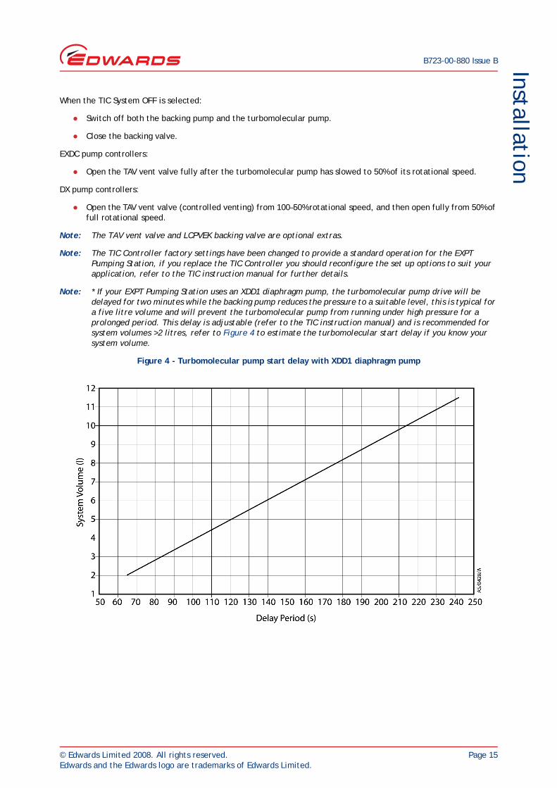
Note: * If your EXPT Pumping Station uses an XDD1 diaphragm pump, the turbomolecular pump drive will be delayed for two minutes while the backing pump reduces the pressure to a suitable level, this is typical for a five litre volume and will prevent the turbomolecular pump from running under high pressure for a prolonged period. This delay is adjustable (refer to the TIC instruction manual) and is recommended for system volumes >2 litres, refer to Figure 4 to estimate the turbomolecular start delay if you know your system volume.
Figure 4 - Turbomolecular pump start delay with XDD1 diaphragm pump
B723-00-880 Issue B
Page 16 © Edwards Limited 2008. All rights reserved.Edwards and the Edwards logo are trademarks of Edwards Limited.
Installation
3.12 Commission the installation
After you have installed the EXPT Pumping Station, use the following procedure to test the system.
1. Make sure that all the electrical connections are secure.
2. Switch on the electrical supply and your exhaust-extraction system (if available).
3. Turn ON the EXPT Pumping Station using the ON/OFF switch positioned on the rear panel. To start-up the equipment, refer to the TIC instruction manual. Check that the equipment operates as described in Section 3.11.
4. Inspect the vacuum, exhaust and pipeline connections and check that there are no leaks. Seal if any leaks are found.
5. Wait until the turbomolecular pump has reached full speed, then select OFF on the front panel of the TIC Controller again; check that both pumps stop.
3.13 Connecting an active gauge
CAUTIONDo not connect Barocel capacitance manometers to the TIC Pumping Station gauge connectors. Doing so will result in damage to the gauge and will invalidate the warranty.
Up to three compatible active gauges can be fitted to the gauge connectors on the rear inside of the EXPT Pumping Station housing, refer to Figure 1. Connect the gauges using Edwards active gauge cables to each of the three sockets, the number indicated above each socket corresponds to the same gauge number shown on the TIC Controller display. This option is only available if the EXPT Pumping Station uses a TIC turbo and instrument controller.
Note: Only one AIGX gauge can be connected to the TIC Pumping Station gauge connectors at a time.
3.14 Connecting the logic interface
CAUTIONDo not earth the logic interface 0 V lines (pins 7, 10, 12, and 13). If you do, you will provide an earth return path for any electrical fault in the pump-motor and this could damage your Controller or your control equipment.
CAUTIONDo not connect voltages greater than 24 V to the logic interface.
The logic interface provides a number of signals that can be used for monitoring the status of your vacuum system, and for controlling certain aspects of its operation. These signals can be broadly divided into three groups, control inputs, control outputs and status outputs.
The EXPT Pumping Station is supplied with an interlock D-connector connected into the logic interface at the rear of the equipment. If you do not intend to connect the logic interface to your system you must use the interlock D-connector, failing to do so will disable a number of control outputs which operate the EXPT system.
WARNING
Do not operate the system with the exhaust pipeline blocked. For example, if your EXPT Pumping Station uses a rotary vane pump, oil mist may be discharged from the oil mist filter and cause injury to people.
© Edwards Limited 2008. All rights reserved. Page 17Edwards and the Edwards logo are trademarks of Edwards Limited.
InstallationB723-00-880 Issue B
Note: The user logic interface on the rear panel offers the same functionality as the logic interface on the TIC Controller. Refer to the TIC instruction manual for further details of this connector.
3.15 Connecting the serial interface
The TIC has two serial communications protocols built in, RS232 and RS485. RS232 is the simplest interface and can be used to allow a host PC to control the TIC. RS485 allows a host PC to control a small network of TICs.
Note: The user serial interface on the rear panel offers the same functionality as the serial interface on the TIC Controller. Refer to the TIC instruction manual for further details of this connector.

B723-00-880 Issue B
Page 18 © Edwards Limited 2008. All rights reserved.Edwards and the Edwards logo are trademarks of Edwards Limited.
This page has been intentionally left blank.
© Edwards Limited 2008. All rights reserved. Page 19Edwards and the Edwards logo are trademarks of Edwards Limited.
Operation
B723-00-880 Issue B
4 Operation4.1 Use of the backing pump controls
If the backing pump has a mode selector and or gas-ballast control, refer to the appropriate backing pump instruction manual to optimise the performance of the pump for your application.
4.2 Start-up
Use the following procedure to start the EXPT Pumping Station. If you wish to reconfigure the operation of the EXPT Pumping Station to suit an application, refer to the TIC instruction manual.
1. Switch on the electrical supply to the EXPT Pumping Station and your exhaust-extraction system (if available).
2. Turn ON the EXPT Pumping Station using the ON/OFF switch positioned on the rear panel.
3. To operate the equipment components, refer to the TIC instruction manual for full operation.
4.3 Shut-down
Use the following procedure to shut down the EXPT Pumping Station.
1. Refer to the TIC Controller instruction manual to stop the turbomolecular pump (TMP) and backing pump operation.
2. Switch off the ON/OFF rocker switch located on the equipment rear panel.
3. Remove the electrical mains supply from the equipment.

B723-00-880 Issue B
Page 20 © Edwards Limited 2008. All rights reserved.Edwards and the Edwards logo are trademarks of Edwards Limited.
This page has been intentionally left blank.
© Edwards Limited 2008. All rights reserved. Page 21Edwards and the Edwards logo are trademarks of Edwards Limited.
Maintenance
B723-00-880 Issue B
5 Maintenance5.1 Safety
When you refer to a manual supplied as a Supplementary Publication, you must obey all of the WARNING and CAUTION instructions in the manual.
A suitably trained and supervised technician must maintain the EXPT Pumping Station.
Allow the pumps to cool to a safe temperature before you start maintenance work.
Check that all the required parts are available and of the correct type before you start work.
Ensure that the maintenance technician is familiar with the safety procedures which relate to the products pumped. Wear the appropriate safety-clothing when you come into contact with contaminated components. Dismantle and clean contaminated components in a fume-cupboard.
Isolate the EXPT Pumping Station and other components in the system from the electrical supply so that they cannot be operated accidentally.
Do not reuse ‘O’ rings and Co-Seals if they are damaged.
Dispose of components, grease and oil safely (refer to Section 6).
Protect sealing-faces from damage.
Do not touch or inhale the thermal breakdown products of fluoroelastomer seals. These breakdown products are very dangerous and may be present if the EXPT Pumping Station has been heated to 260 °C and above.
Leak-test the system after maintenance and seal any leaks found if you have disconnected any vacuum or exhaust pipeline connections.
5.2 Maintenance plan
The following documents list the minimum maintenance operations necessary to maintain the EXPT Pumping Station in normal use.
More frequent maintenance may be necessary if the EXPT Pumping Station has been used to pump corrosive or abrasive gases and vapours. If necessary, adjust the maintenance plan according to your experience.
WARNING
Obey the safety instructions given below and take note of appropriate precautions. If you do not, you can cause injury to people and damage to equipment.
EXT pumpsTurbomolecular pumps EXT70H / EXT255H 24 V (B722-20-880)
EXT75DX / EXT255DX (B722-40-880)Backing pumpsDiaphragm pump XDD1 (A746-01-885)Rotary vane pumps E2M0.7 / E2M1.5 (A371-22-880)
RV3 / RV5 / RV8 / RV12 (A652-01-880)Scroll pumps XDS5 / XDS10 (A726-01-880)
B723-00-880 Issue B
Page 22 © Edwards Limited 2008. All rights reserved.Edwards and the Edwards logo are trademarks of Edwards Limited.
Maintenance
5.3 Inspect the hoses, pipelines and connections
1. If the turbomolecular pump on your EXPT Pumping Station is water-cooled:
Inspect all of the cooling-water connections and check that they are secure. Tighten any loose connections.
Inspect all cooling-water hoses, pipelines and connections and check that they are not corroded or damaged and that they do not leak. Replace or repair any corroded or damaged component and seal any leaks found.
2. Inspect all of the electrical connections and check that they are secure. Tighten any loose connections.
3. Inspect all of the electrical cables and check that they are not damaged and have not overheated. Replace or repair any damaged or overheated cable.
4. Inspect all of the vacuum and exhaust connections and check that they are secure. Tighten any loose connections.
5. Inspect all of the vacuum and exhaust pipelines and check that they are not corroded or damaged and that they do not leak. Replace or repair any corroded or damaged component and seal any leaks found.
5.4 Trouble-shooting
For trouble-shooting instructions on the EXPT Pumping Station, refer to the following documents:
EXT pumpsTurbomolecular pumps EXT70H / EXT255H 24 V (B722-20-880)
EXT75DX / EXT255DX (B722-40-880)Backing pumpsDiaphragm pump XDD1 (A746-01-885)Rotary vane pumps E2M0.7 / E2M1.5 (A371-22-880)
RV3 / RV5 / RV8 / RV12 (A652-01-880)Scroll pumps XDS5 / XDS10 (A726-01-880)
TIC controllerTIC controller Turbo controller (D397-12-880)
Turbo instrument controller (D397-22-880)
© Edwards Limited 2008. All rights reserved. Page 23Edwards and the Edwards logo are trademarks of Edwards Limited.
Storage and disposalB723-00-880 Issue B
6 Storage and disposalNote: We recommend that you avoid long-term storage of the EXPT Pumping Station. If you will store the EXPT
Pumping Station for several months, refer to the storage instructions in the relevant instruction manual.
6.1 Storage
Use the following procedure to store the EXPT Pumping Station:
1. Shut down the EXPT Pumping Station as described in Section 4.3.
2. Isolate the EXPT Pumping Station from the electrical supply and disconnect it from the vacuum system.
3. Drain the oil from the backing pump (rotary vane pumps only) as described in the instruction manual for the pump. Refer to the following documents:
4. Place protective covers over the inlet and outlet-flanges.
5. For the fastest pump-down after the EXPT Pumping Station is re-installed, seal the turbomolecular pump inside a plastic bag together with a suitable desiccant.
6. Store the EXPT Pumping Station in cool, dry conditions until required for use.
6.2 Disposal
Dispose of the EXPT Pumping Station and any components safely in accordance with all local and national safety and environmental requirements.
Particular care must be taken with components which have been contaminated with dangerous process substances.
Rotary vane pumps E2M0.7 / E2M1.5 (A371-22-880)RV3 / RV5 / RV8 / RV12 (A652-01-880)

B723-00-880 Issue B
Page 24 © Edwards Limited 2008. All rights reserved.Edwards and the Edwards logo are trademarks of Edwards Limited.
This page has been intentionally left blank.
© Edwards Limited 2008. All rights reserved. Page 25Edwards and the Edwards logo are trademarks of Edwards Limited.
Spares and accessoriesB723-00-880 Issue B
7 Spares and accessories7.1 Introduction
Edwards products, spares and accessories are available from Edwards companies in Belgium, Brazil, Canada, France, Germany, Hong Kong, Italy, Japan, Korea, Switzerland, United Kingdom, U.S.A and a worldwide network of distributors. The majority of these centres employ Service Engineers who have undergone comprehensive Edwards training courses.
Order spare parts and accessories from your nearest Edwards company or distributor. When you order, state for each part required:
Model and Item Number of your equipment
Serial number (if any)
Item Number and description of the part.
Fit accessories as described in the Supplementary Publications and in the instruction manual supplied with the accessory.
7.2 Spares
The spares available for use with the EXPT Pumping Station (including replacement component parts) are listed in the instruction manuals supplied as Supplementary Publications.
7.3 Accessories
For accessories on the EXPT Pumping Station, refer to the following documents:
7.3.1 BX bakeout band
The BX bakeout band should only be used on turbomolecular pumps intended to be used remotely away from the EXPT Pumping Station. For further details please contact Edwards UK.
EXT pumpsTurbomolecular pumps EXT70H / EXT255H 24 V (B722-20-880)
EXT75DX / EXT255DX (B722-40-880)Backing pumpsDiaphragm pump XDD1 (A746-01-885)Rotary vane pumps E2M0.7 / E2M1.5 (A371-22-880)
RV3 / RV5 / RV8 / RV12 (A652-01-880)Scroll pumps XDS5 / XDS10 (A726-01-880)
TIC controllerTIC controller Turbo controller (D397-12-880)
Turbo instrument controller (D397-22-880)

B723-00-880 Issue B
Page 26 © Edwards Limited 2008. All rights reserved.Edwards and the Edwards logo are trademarks of Edwards Limited.
This page has been intentionally left blank.
IndexB723-00-880 Issue B
© Edwards Limited 2008. All rights reserved. Page 27Edwards and the Edwards logo are trademarks of Edwards Limited.
AAccessories ............................................ 2, 25Additional earth bonding ............................... 14
BBX bakeout band ......................................... 25
CChecklist of components ............................... 11Commission the installation ............................ 16Configure the EXPT pumping station ................. 14Connect the electrical supply ......................... 14Connect the EXPT pumping station to your vacuum system ........................................... 14Connect to your exhaust extraction system ......... 14Connecting an active gauge ............................ 16Connecting the logic interface ........................ 16Connecting the serial interface ....................... 17Connections ................................................8
DDescription .................................................2Disposal ................................................... 23
EEarth stud ...................................................8Electrical connections ....................................8Electrical data .............................................6Electrical protection ......................................2
FFill the rotary pump with oil ........................... 13Fit accessories (optional) ............................... 13Fuse ratings .................................................7
GGeneral description of the EXPT pumping station major components .........................................2
IInspect the hoses, pipelines and connections ....... 22Installation ................................................ 11Introduction ................................................1
LLegislation and standards ................................7Locate the EXPT pumping station ..................... 12
MMaintenance .............................................. 21Maintenance plan ........................................ 21
OOperating and storage data ..............................7Operation ................................................. 19Overview ....................................................2
SSafety ..................................................... 11Shut-down ................................................ 19Spares ..................................................... 25Start-up ................................................... 19Storage .................................................... 23
TTechnical data .............................................5Trouble-shooting ........................................ 22
UUnpack and inspect ..................................... 11Use of the backing pump controls .................... 19
XXDS scroll pump silencer ............................... 13
Index

B723-00-880 Issue B
Page 28 © Edwards Limited 2008. All rights reserved.Edwards and the Edwards logo are trademarks of Edwards Limited.
This page has been intentionally left blank.