Embed Size (px)
Citation preview
Setup & User Guide
Prognosis IP Office Appliance
Page 2
Copyright Copyright 2015 Integrated Research Limited (ABN 76 003 588 449). All rights reserved. This guide is protected by copyright law and international treaties. No part of this document may be reproduced in any form or distributed, and no derivative works such as translations may be made, without prior written permission from Integrated Research. Unauthorized reproduction or distribution of this document or of the computer software, or any portion of it, may result in severe civil and criminal penalties, and will be prosecuted to the maximum extent possible under the law.
Date of Issue: 6 May 2015 Product Version: Prognosis 10.3
Trademarks Prognosis and IR are registered trademarks of Integrated Research Limited.
Other product names mentioned in this manual may be trademarks, registered trademarks and/or service marks of their respective owners and may not be used for commercial purposes without express permission from their respective owners.
Third Party Software License Notices Please refer to the Third Party Software License Guide on the Prognosis installation CD or in the Documentation folder of the Prognosis installation path for details of third party software license notices.
Disclaimer The information in this guide is published as is and without warranties of any kind, expressed or implied, including those regarding the accuracy or completeness of the information, warranties of merchantability and fitness for a particular purpose, or those arising from a course of dealing, usage or trade practice.
In no event will Integrated Research be liable for any special, incidental, consequential, or indirect damages, or for any damages whatsoever (including, without limitation, those resulting from lost profits, lost data or business interruption) in connection with the furnishing, performance, use, inability to use, or the results of this guide. The information in this guide is subject to change without notice.
Latest Updates The content in this document was current at the time of publication. However, for the latest updates please refer to the Prognosis Online WebHelp via the user interface or through:
https://online.prognosis.com
Setup & User Guide
Page 3
Contents About this Guide ........................................................................................................................................ 4 Introduction ................................................................................................................................................ 5 Getting Started........................................................................................................................................... 6 Prognosis Login Procedure ....................................................................................................................... 8 Configuration ............................................................................................................................................. 9
Configuration for Avaya IP Office ..................................................................................................10 Configuration for Avaya Aura SBC-E.............................................................................................17 Configuring Prognosis Alerts .........................................................................................................24
Monitoring Data ........................................................................................................................................26 Troubleshooting ........................................................................................................................................27 Prognosis IP Office Appliance Setup Tool ................................................................................................29
Setup & User Guide
Page 4
About this Guide Before reading this documentation it is expected that you will have an understanding of the environment, the hardware and the various software applications that you are intending to monitor. Where necessary this guide will cover the interaction between IR Prognosis and other hardware/software but it will not provide detailed information about their operations. Please refer to the individual hardware/software manuals and guides for such information.
Audience and Purpose This guide is intended as a reference source for Operators who are responsible for monitoring system operations and data. It provides a basic overview of using the Prognosis user interfaces plus detailed information about setting up and using Prognosis to monitor specific Unified Communications (UC) environments.
Online Help Complete details of the Prognosis application can be found in the Online Help Center. This can be accessed from the Help button on the Prognosis user interface or, for registered users, through the PrognosisOnline web site (https://online.prognosis.com).
Setup & User Guide
Page 5
Introduction IR Prognosis for Unified Communications is multi-vendor software product which is designed to provide a comprehensive monitoring and management platform for Unified Communications (UC) environments. It does this by collecting data, filtering it as required and then presenting it in a 'user-friendly' format, all in 'real-time'. Additional functions allow for data to be collected into databases for further analysis and reporting, generating alerts when predefined conditions are exceeded, and automatically running commands to rectify system problems.
The Prognosis IP Office Appliance is a pre-packaged VM (Virtual Machine) that has a copy of the Prognosis system monitoring application pre-installed. This VM copy of Prognosis is a scaled down version which is limited to montioring Avaya IP Office and Avaya Aura SBC-E environments.
The purpose of this VM edition is to provide a Prognosis system that is simple to install and easy to maintain for smaller environments.
Compatibility The Prognosis IP Office Application OVA is compatible with the following VMware products:
• vSphere ESXi 5.1 or later • Workstation 9.0 • Workstation 10.0

Prognosis IP Office Appliance
Page 6
Getting Started To install and setup the IR Prognosis IP Office Appliance the following steps need to be completed:
1) Obtain the Prognosis OVA File Step 1 Log on to the Prognosis Online web site:
https://online.prognosis.com
Step 2 From the toolbar go to the Products > Download section.
Step 3 Scroll down to the Prognosis IP Office Appliance section.
Step 4 Click on the Download link and the required OVA file download will commence.
2) Deploy the OVA Template to the VMware Machine To create the Virtual Machine (VM), simply deploy the OVA file to the VMware environment. To do this carry out either of the the following procedures depending on the VMware version being used.
The Prognosis OVA file contains all the required VM machine specifications, so it will not be necessary to manually provide any details such as CPU’s, memory, disk size etc.
Using vSphere ESXi
Step 1 Open VMware vSphere ESXi.
Step 2 From the File menu, select Deploy OVF Template.
Step 3 Click the Browse button, locate the OVA file and click Open.. Step 4 The Deployment Wizard will open, click Next. Step 5 On the ‘OVF Template Details’ screen, click Next. Step 6 On the ‘Name and Location’ screen provide a name and location for the VM files, then click Next.. Step 7 On the ‘Storage’ screen provide the required storage details within the ESXi server, then click Next.
Step 8 On the ‘Disk Format’ screen select the Disk format, choose between ‘thick’ or ‘thin’ provisioning, then click Next.
Step 9 On the ‘Set Properties’ screen provide the required machine and domain details, then click Next . Step 10 Verify all details then click Finish.
Using VMware Workstation
Step 1 Open VMware Workstation.
Step 2 From the File menu, select Open.
Step 3 Use the Browser to locate and select the OVA file and then click Open.
Step 4 On the ‘Store New Virtual Machine’ screen provide a name for the VM and specify a location for the VM files.
Step 5 When complete, click Import.
Setup & User Guide
Page 7
3) Start the Virtual Machine Once the VM has been created, start it up and then log on to the machine via Remote Desktop or open a Console from VMware using the MS Windows Administrator credentials or an account with Administration permissions.
There is a default user called ‘Prognosis’ which is needed to send updates and patches to the system, please do not modify this account.
4) Register the Appliance On start up, the Prognosis IP Office Appliance setup tool will open. The next step will be to obtain a Prognosis license. To do this use the following steps:
Step 1 In the Registration section, click on the Register button.
Step 2 Provide your registration details, these will be sent to IR and a confirmation email will be sent to the email address supplied with the required verification code.
Step 3 When the email is received, open it and make a note of the verification code.
Step 4 Return to the Appliance setup interface and click on the Enter Verficiation Code button which will now be displayed in the Registration section. Enter the verification code from the email.
Step 5 In the Licensing section click the Get License button.
Step 6 If the license is available, it will now be downloaded and installed into Prognosis. Prognosis will now start and the Diagnostic and Connectivity options in the Appliance setup tool will be enabled.
If the license if not yet available, then please wait and retry Step 5. Depending on network availability the license generation may take between 2 minutes and 24 hours.
Prognosis IP Office Appliance
Page 8
Prognosis Login Procedure Use the following procedure to access the IR Prognosis Web Application.
Procedure Step 1 On the machine where the Prognosis Web Application is installed, from the Windows Start menu
select:
All Programs > Prognosis > Prognosis View Systems (to open the data monitoring interface)
or
All Programs > Prognosis > Prognosis Administration (to open the administration tool)
Alternatively, from the same or remote machine, open a web browser and input the following URL:
https://<ip-address>/Prognosis/Login
<ip-address> can be the machine name or the IP address where the Prognosis Management or Monitoring Server has been installed.
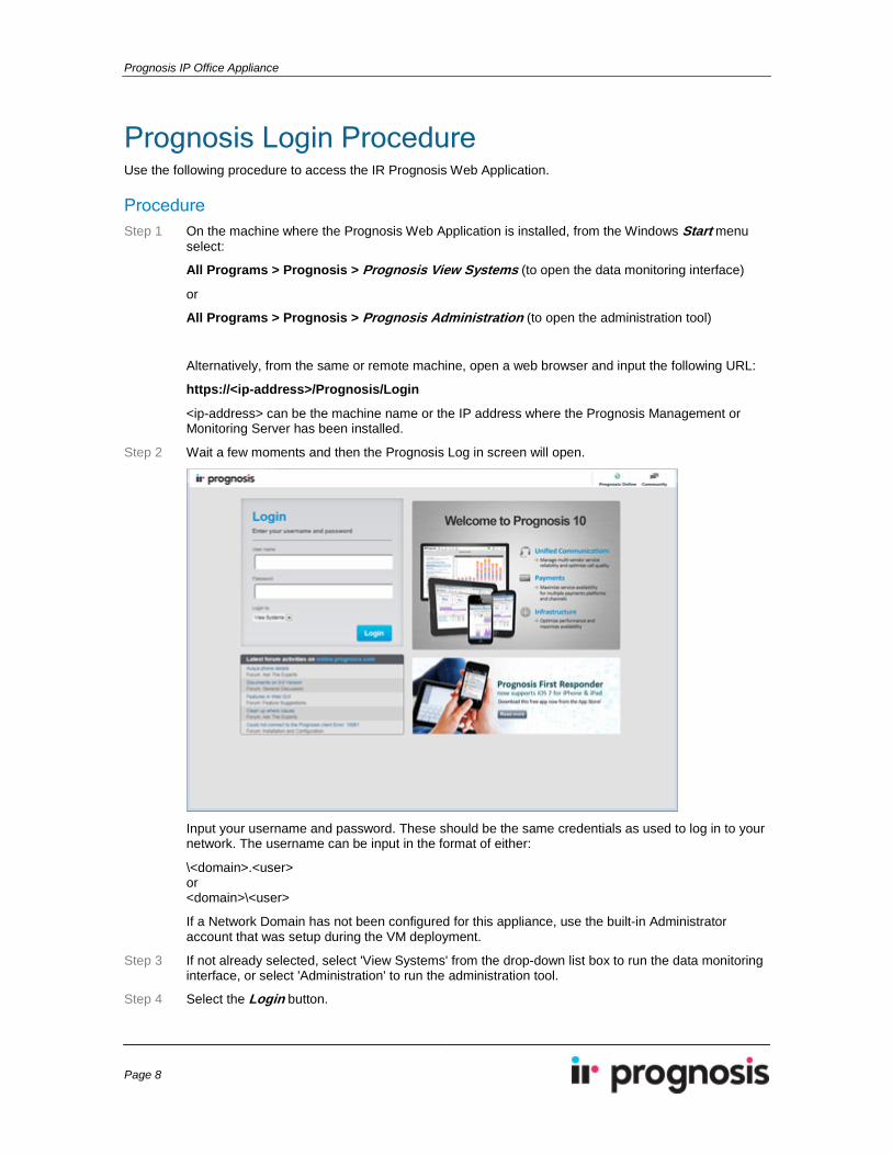
Step 2 Wait a few moments and then the Prognosis Log in screen will open.
Input your username and password. These should be the same credentials as used to log in to your network. The username can be input in the format of either:
\<domain>.<user> or <domain>\<user>
If a Network Domain has not been configured for this appliance, use the built-in Administrator account that was setup during the VM deployment.
Step 3 If not already selected, select 'View Systems' from the drop-down list box to run the data monitoring interface, or select 'Administration' to run the administration tool.
Step 4 Select the Login button.
Setup & User Guide
Page 9
Configuration Once the IR Prognosis IP Office Appliance has been deployed and registered, the next step is to configure Prognosis to monitor the Avaya environments. This will require the following three configuration tasks to be completed.
For details see the following topics:
• Configuration for Prognosis to monitor Avaya IP Office (page 10).
• Configuration for Prognosis to monitor Avaya Aura SBC-E (page 17).
• Configuration for Prognosis to send emails alerts (page 24).
Prognosis IP Office Appliance
Page 10
Configuration for Avaya IP Office A number of configuration procedures need to be completed in order for Prognosis to start collecting Avaya IP Office data. This section provides detailed instructions on how to carry out these steps.
For details see the following topics:
• Avaya IP Office Setup (page 11)
• Prognosis Server Configuration (page 14)
Setup & User Guide
Page 11
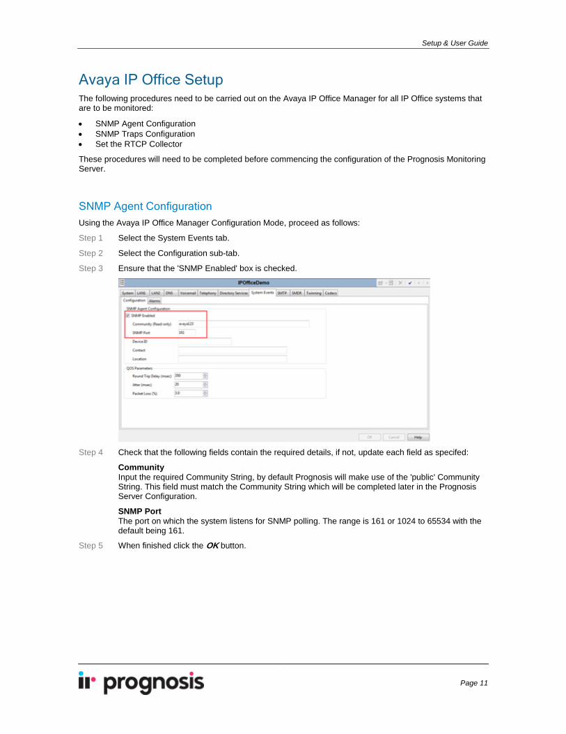
Avaya IP Office Setup The following procedures need to be carried out on the Avaya IP Office Manager for all IP Office systems that are to be monitored:
• SNMP Agent Configuration • SNMP Traps Configuration • Set the RTCP Collector
These procedures will need to be completed before commencing the configuration of the Prognosis Monitoring Server.
SNMP Agent Configuration Using the Avaya IP Office Manager Configuration Mode, proceed as follows:
Step 1 Select the System Events tab.
Step 2 Select the Configuration sub-tab.
Step 3 Ensure that the 'SNMP Enabled' box is checked.
Step 4 Check that the following fields contain the required details, if not, update each field as specifed:
Community Input the required Community String, by default Prognosis will make use of the 'public' Community String. This field must match the Community String which will be completed later in the Prognosis Server Configuration.
SNMP Port The port on which the system listens for SNMP polling. The range is 161 or 1024 to 65534 with the default being 161.
Step 5 When finished click the OK button.

Prognosis IP Office Appliance
Page 12
SNMP Traps Configuration Using the Avaya IP Office Manager Configuration Mode, proceed as follows:
Step 1 Select the System Events tab.
Step 2 Select the 'Alarms' sub-tab.
Step 3 Select the 'Trap' radio button.
Step 4 Complete the following fields:
IP Address In the 'IP Address' field, input the IP address of the Prognosis server. This is where the SNMP trap information will be sent.
Port The SNMP transmit port. This can be left at the default port number 162.
Community The SNMP Community String for the transmitted traps. This must match the Community String set on the Prognosis server. The default is 'public'.
Format Leave as the default, 'IP Office'
Minimum Security Level Set as required.
Warnings (Default) All events, from Warnings to Critical, are sent.
Minor Minor, major, and critical events are sent. Warnings are not sent.
Major Major and critical events are sent. Warnings and minor events will not be sent.
Events Set which types of system events should be collected and sent to Prognosis. It is recommended that all items are selected in order to receive comprehensive alerting on all conditions.
Step 5 When finished click the OK button.
Setup & User Guide
Page 13
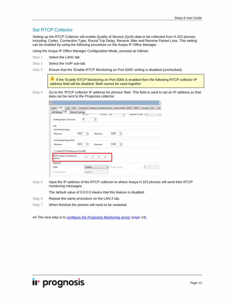
Set RTCP Collector Setting up the RTCP Collector will enable Quality of Service (QoS) data to be collected from H.323 phones, including; Codec, Connection Type, Round Trip Delay, Receive Jitter and Receive Packet Loss. This setting can be enabled by using the following procedure on the Avaya IP Office Manager.
Using the Avaya IP Office Manager Configuration Mode, proceed as follows:
Step 1 Select the LAN1 tab.
Step 2 Select the VoIP sub-tab.
Step 3 Ensure that the 'Enable RTCP Monitoring on Port 5005' setting is disabled (unchecked).
If the 'Enable RTCP Monitoring on Port 5005 is enabled then the following RTCP collector IP address field will be disabled. Both cannot be used together.
Step 4 Go to the 'RTCP collector IP address for phones' field. This field is used to set an IP address so that data can be sent to the Prognosis collector.
Step 5 Input the IP address of the RTCP collector to where Avaya H.323 phones will send their RTCP
monitoring messages.
The default value of 0.0.0.0 means that this feature is disabled.
Step 6 Repeat this same procedure on the LAN 2 tab.
Step 7 When finished the phones will need to be restarted.
>> The next step is to configure the Prognosis Monitoring server (page 14).
Prognosis IP Office Appliance
Page 14
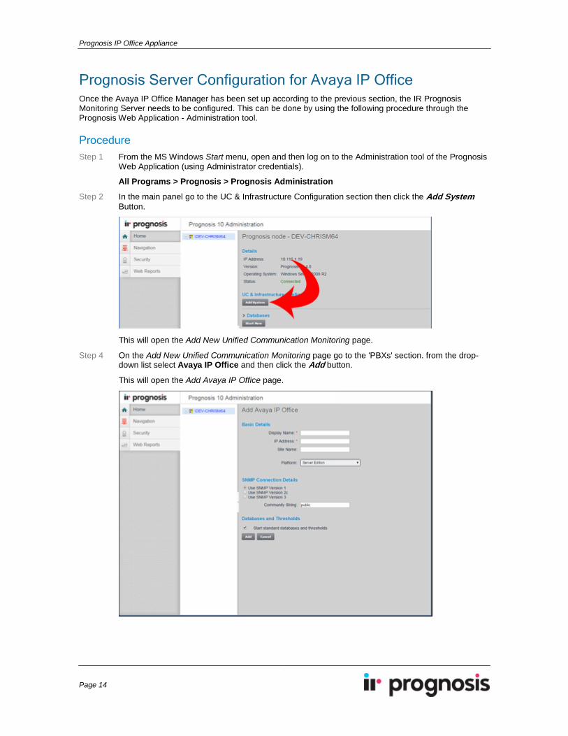
Prognosis Server Configuration for Avaya IP Office Once the Avaya IP Office Manager has been set up according to the previous section, the IR Prognosis Monitoring Server needs to be configured. This can be done by using the following procedure through the Prognosis Web Application - Administration tool.
Procedure Step 1 From the MS Windows Start menu, open and then log on to the Administration tool of the Prognosis
Web Application (using Administrator credentials).
All Programs > Prognosis > Prognosis Administration
Step 2 In the main panel go to the UC & Infrastructure Configuration section then click the Add System Button.
This will open the Add New Unified Communication Monitoring page.
Step 4 On the Add New Unified Communication Monitoring page go to the 'PBXs' section. from the drop-down list select Avaya IP Office and then click the Add button.
This will open the Add Avaya IP Office page.
Setup & User Guide
Page 15
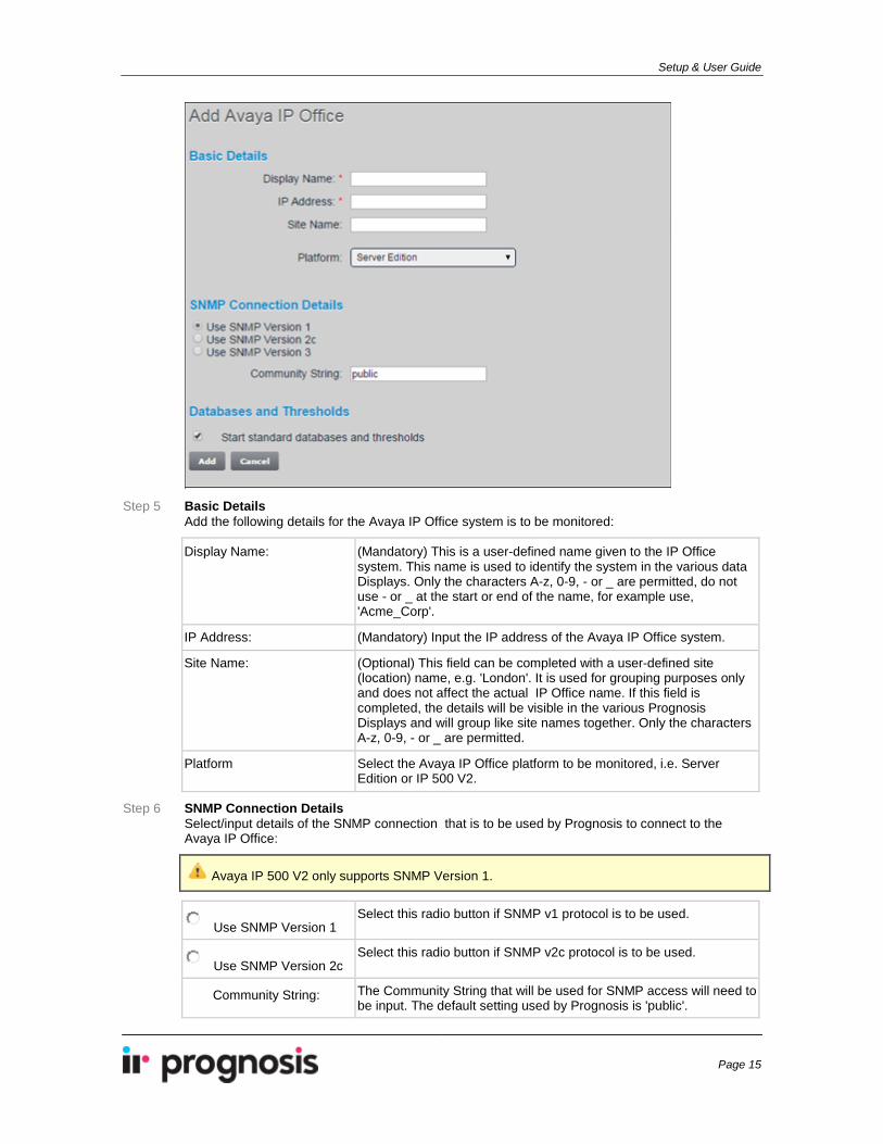
Step 5 Basic Details
Add the following details for the Avaya IP Office system is to be monitored:
Display Name: (Mandatory) This is a user-defined name given to the IP Office system. This name is used to identify the system in the various data Displays. Only the characters A-z, 0-9, - or _ are permitted, do not use - or _ at the start or end of the name, for example use, 'Acme_Corp'.
IP Address: (Mandatory) Input the IP address of the Avaya IP Office system.
Site Name: (Optional) This field can be completed with a user-defined site (location) name, e.g. 'London'. It is used for grouping purposes only and does not affect the actual IP Office name. If this field is completed, the details will be visible in the various Prognosis Displays and will group like site names together. Only the characters A-z, 0-9, - or _ are permitted.
Platform Select the Avaya IP Office platform to be monitored, i.e. Server Edition or IP 500 V2.
Step 6 SNMP Connection Details Select/input details of the SNMP connection that is to be used by Prognosis to connect to the Avaya IP Office:
Avaya IP 500 V2 only supports SNMP Version 1.
Use SNMP Version 1 Select this radio button if SNMP v1 protocol is to be used.
Use SNMP Version 2c Select this radio button if SNMP v2c protocol is to be used.
Community String: The Community String that will be used for SNMP access will need to be input. The default setting used by Prognosis is 'public'.

Prognosis IP Office Appliance
Page 16
Step 7 Databases and Thresholds Normally, once the configuration is complete, a number of Databases and Thresholds need to be started. The "Start standard databases and thresholds' setting, which is activated by default, will automatically carry this out after the configuration has been added. Should it not be required to start the Databases and Threshold, this setting can be disabled by unchecking the adjacent check box.
Step 8 When completed click the Add button to save the changes, or click the Cancel button to cancel the current activity and return to the previous screen without saving any changes.
Setup & User Guide
Page 17
Configuration for Avaya Aura SBC-E A number of configuration procedures need to be completed in order for Prognosis to start collecting Avaya Aura SBC-E data. This section provides detailed instructions on how to carry out these steps.
For details see the following topics:
• Avaya Aura SBC-E Setup (page 18). • Prognosis Server Configuration (page 22).
Prognosis IP Office Appliance
Page 18
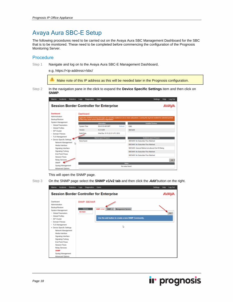
Avaya Aura SBC-E Setup The following procedures need to be carried out on the Avaya Aura SBC Management Dashboard for the SBC that is to be monitored. These need to be completed before commencing the configuration of the Prognosis Monitoring Server.
Procedure Step 1 Navigate and log on to the Avaya Aura SBC-E Management Dashboard,
e.g. https://<ip-address>/sbc/
Make note of this IP address as this will be needed later in the Prognosis configuration.
Step 2 In the navigation pane in the click to expand the Device Specific Settings item and then click on SNMP.
This will open the SNMP page.
Step 3 On the SNMP page select the SNMP v1/v2 tab and then click the Add button on the right.
Setup & User Guide
Page 19
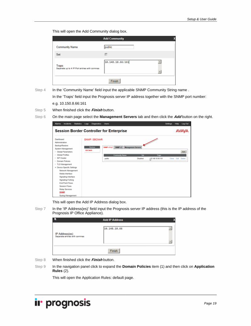
This will open the Add Community dialog box.
Step 4 In the ‘Community Name’ field input the applicable SNMP Community String name .
In the ‘Traps’ field input the Prognosis server IP address together with the SNMP port number:
e.g. 10.150.8.66:161
Step 5 When finished click the Finish button.
Step 6 On the main page select the Management Servers tab and then click the Add button on the right.
This will open the Add IP Address dialog box.
Step 7 In the ‘IP Address(es)’ field input the Prognosis server IP address (this is the IP address of the Prognosis IP Office Appliance).
Step 8 When finished click the Finish button.
Step 9 In the navigation panel click to expand the Domain Policies item (1) and then click on Application Rules (2).
This will open the Application Rules: default page.
Prognosis IP Office Appliance
Page 20
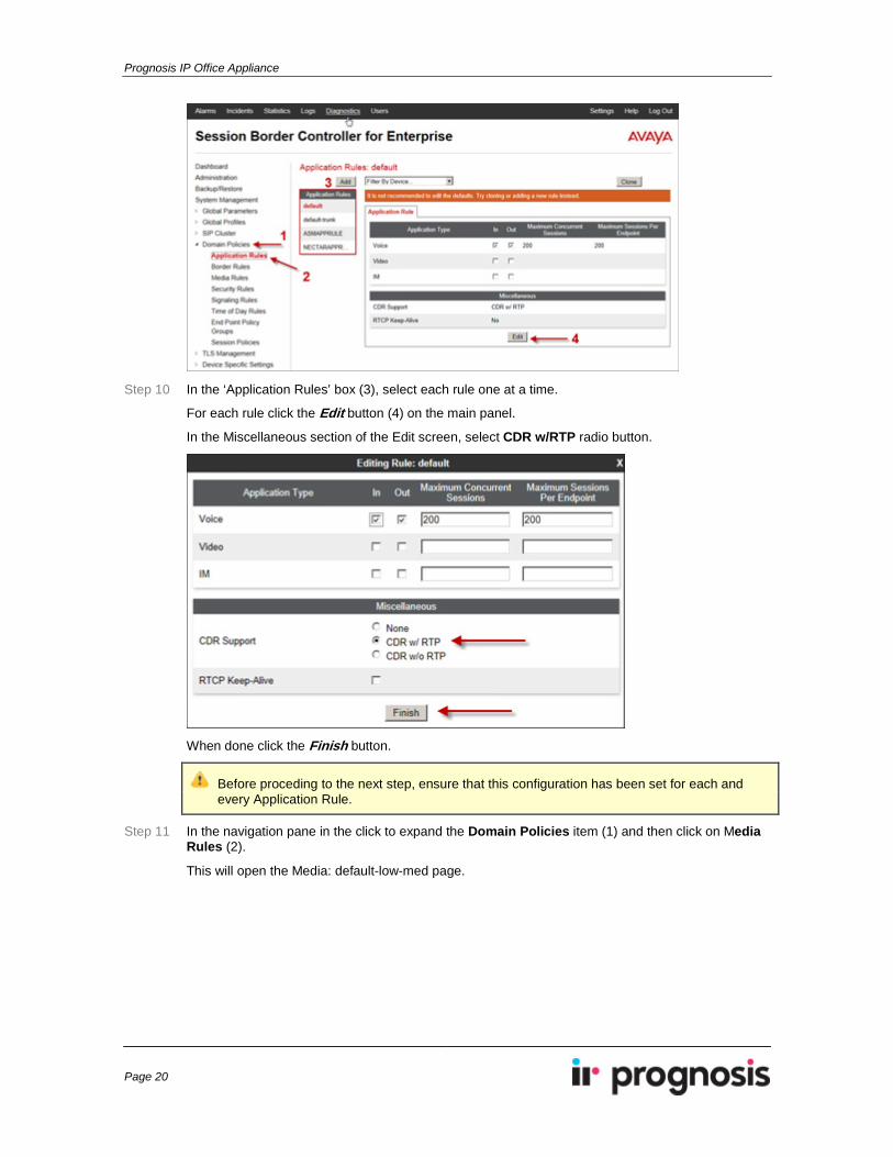
Step 10 In the ‘Application Rules’ box (3), select each rule one at a time.
For each rule click the Edit button (4) on the main panel.
In the Miscellaneous section of the Edit screen, select CDR w/RTP radio button.
When done click the Finish button.
Before proceding to the next step, ensure that this configuration has been set for each and every Application Rule.
Step 11 In the navigation pane in the click to expand the Domain Policies item (1) and then click on Media Rules (2).
This will open the Media: default-low-med page.
Setup & User Guide
Page 21
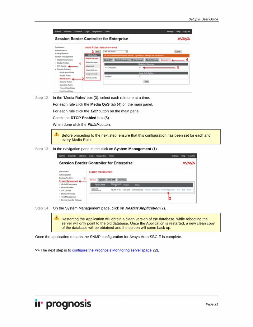
Step 12 In the ‘Media Rules’ box (3), select each rule one at a time.
For each rule click the Media QoS tab (4) on the main panel.
For each rule click the Edit button on the main panel.
Check the RTCP Enabled box (5).
When done click the Finish button.
Before proceding to the next step, ensure that this configuration has been set for each and every Media Rule.
Step 13 In the navigation pane in the click on System Management (1).
Step 14 On the System Management page, click on Restart Application (2).
Restarting the Application will obtain a clean version of the database, while rebooting the server will only point to the old database. Once the Application is restarted, a new clean copy of the database will be obtained and the screen will come back up.
Once the application restarts the SNMP configuration for Avaya Aura SBC-E is complete.
>> The next step is to configure the Prognosis Monitoring server (page 22).
Prognosis IP Office Appliance
Page 22
Prognosis Server Configuration for Avaya Aura SBC-E Once the Avaya Aura SBC-E (ASBCE) device has been set up according to the previous section, the Prognosis Monitoring Server needs to be configured. This can be done by using the following procedure through the Prognosis Web Application - Administration tool.
Procedure Step 1 From the MS Windows Start menu, open and then log on to the Administration tool of the Prognosis
Web Application (using Adminstrator credentials).
All Programs > Prognosis > Prognosis Administration
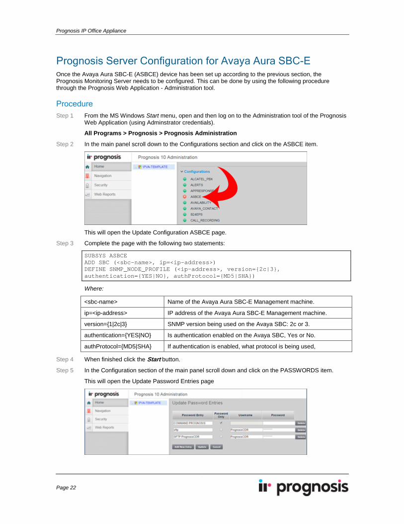
Step 2 In the main panel scroll down to the Configurations section and click on the ASBCE item.
This will open the Update Configuration ASBCE page.
Step 3 Complete the page with the following two statements:
SUBSYS ASBCE ADD SBC (<sbc-name>, ip=<ip-address>) DEFINE SNMP_NODE_PROFILE (<ip-address>, version={2c|3}, authentication={YES|NO}, authProtocol={MD5|SHA})
Where:
<sbc-name> Name of the Avaya Aura SBC-E Management machine.
ip=<ip-address> IP address of the Avaya Aura SBC-E Management machine.
version={1|2c|3} SNMP version being used on the Avaya SBC: 2c or 3.
authentication={YES|NO} Is authentication enabled on the Avaya SBC, Yes or No.
authProtocol={MD5|SHA} If authentication is enabled, what protocol is being used,
Step 4 When finished click the Start button.
Step 5 In the Configuration section of the main panel scroll down and click on the PASSWORDS item.
This will open the Update Password Entries page
Setup & User Guide
Page 23
On this page the SNMP Community String or password details are added . This is necessary if the SBC-E server has been set up with SNMP v2c (Community String) or v3 (password).
Step 6 Click on the Add New Entry button and then add the password information in the following format:
SNMP Version 2c:
Password Entry Password Only
Username Password
snmpv2c:<sbc-name> Yes Not required <snmp-community string>
SNMP Version 3:
Password Entry Password Only
Username Password
snmpv3:ASBCE:<sbc-name> No <snmp-username> <snmp-password>
Step 7 After completing each entry click the Update button.
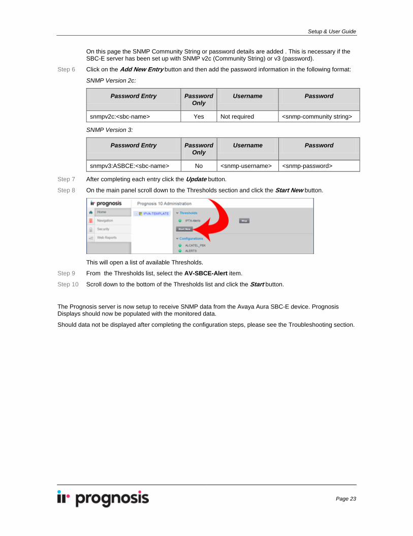
Step 8 On the main panel scroll down to the Thresholds section and click the Start New button.
This will open a list of available Thresholds.
Step 9 From the Thresholds list, select the AV-SBCE-Alert item.
Step 10 Scroll down to the bottom of the Thresholds list and click the Start button.
The Prognosis server is now setup to receive SNMP data from the Avaya Aura SBC-E device. Prognosis Displays should now be populated with the monitored data.
Should data not be displayed after completing the configuration steps, please see the Troubleshooting section.
Prognosis IP Office Appliance
Page 24
Configuring Prognosis Alerts This procedure is used to configure Prognosis to send alert messages via email to a nominated email destination. To do this use the following steps.
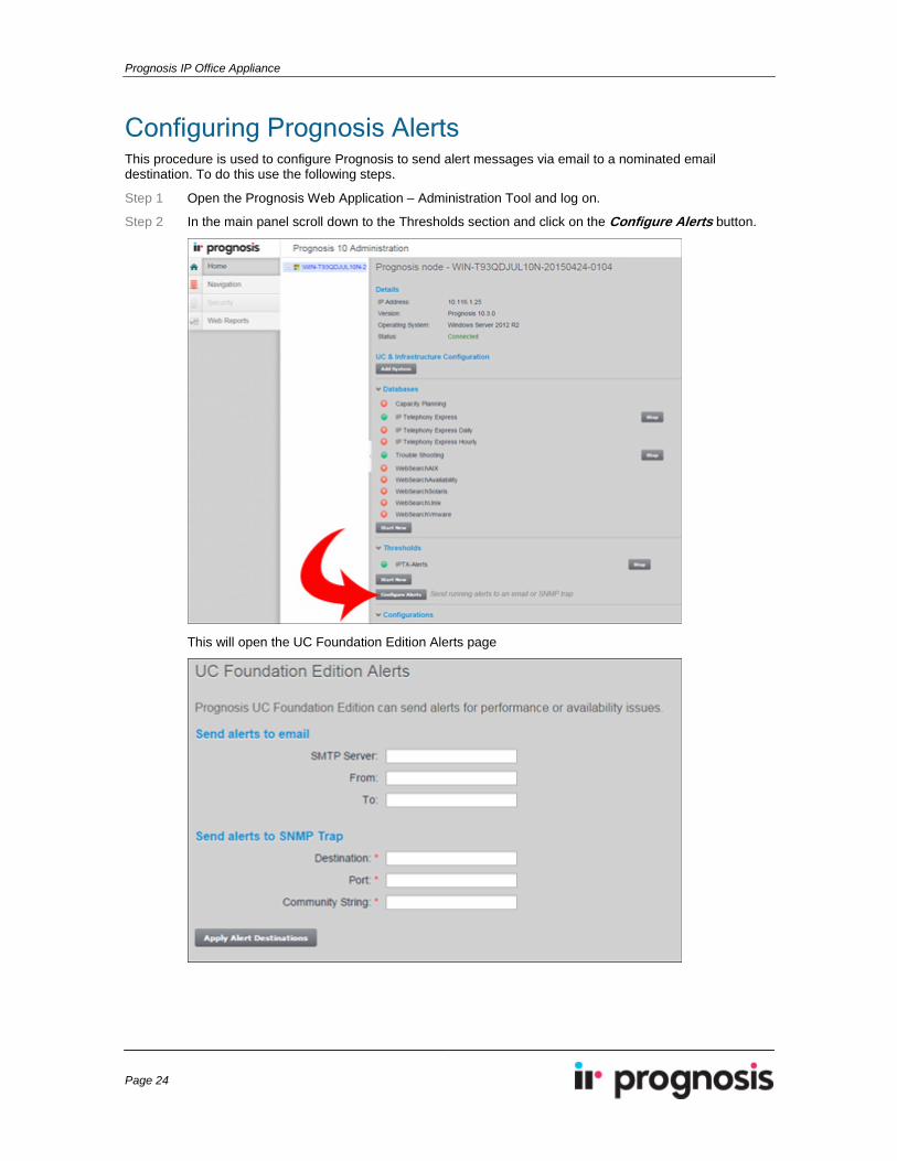
Step 1 Open the Prognosis Web Application – Administration Tool and log on.
Step 2 In the main panel scroll down to the Thresholds section and click on the Configure Alerts button.
This will open the UC Foundation Edition Alerts page
Setup & User Guide
Page 25
Step 3 Complete the page with the following details:
SMTP Server IP address or name of the domain email server.
From Origin email address for all messages generated by Prognosis.
To Destination address for all email alterts generated by Prognosis.
Destination (*) 127.0.0.1
Port (*) 161
Community String (*) default
(*) These SNMP Trap details are not used by this Appliance but need to be configured in order to complete the form, therefore simply use the default values shown above.
Step 4 When complete click the Apply Alert Destinations button to save the details.
Prognosis IP Office Appliance
Page 26
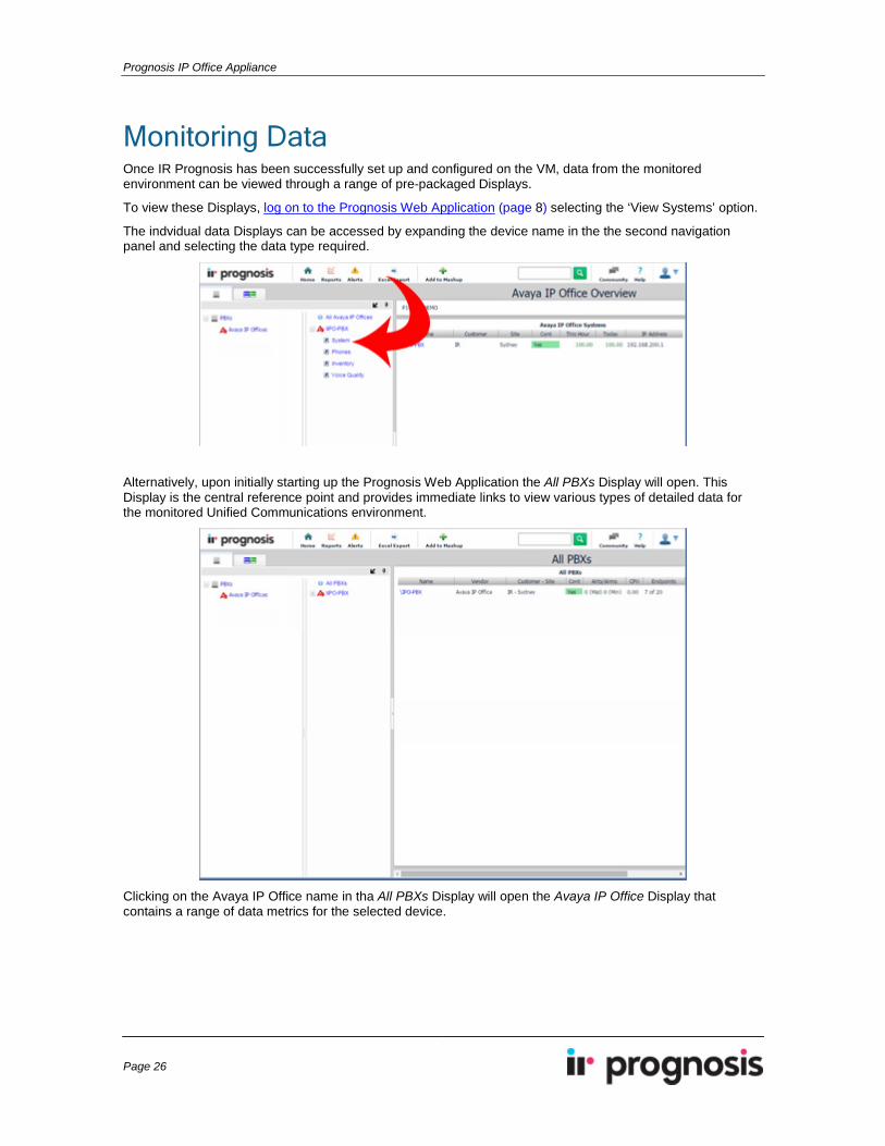
Monitoring Data Once IR Prognosis has been successfully set up and configured on the VM, data from the monitored environment can be viewed through a range of pre-packaged Displays.
To view these Displays, log on to the Prognosis Web Application (page 8) selecting the ‘View Systems’ option.
The indvidual data Displays can be accessed by expanding the device name in the the second navigation panel and selecting the data type required.
Alternatively, upon initially starting up the Prognosis Web Application the All PBXs Display will open. This Display is the central reference point and provides immediate links to view various types of detailed data for the monitored Unified Communications environment.
Clicking on the Avaya IP Office name in tha All PBXs Display will open the Avaya IP Office Display that contains a range of data metrics for the selected device.
Setup & User Guide
Page 27
Troubleshooting This procedure describes troubleshooting the connection from the Avaya Aura SBC-E server to the Prognosis Monitoring server.
Procedure Step 1 Navigate and log on to the Avaya Aura SBC-E Management Dashboard,
e.g. https://<ip-address>/sbc/
Make note of this IP address as this will be needed later in the Prognosis configuration.
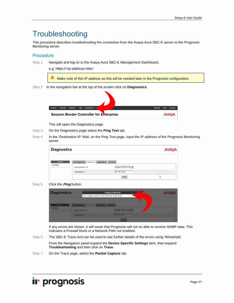
Step 2 In the navigation bar at the top of the screen click on Diagnostics.
This will open the Diagnostics page.
Step 3 On the Diagnostics page select the Ping Test tab.
Step 4 In the ‘Destination IP’ field, on the Ping Test page, input the IP address of the Prognosis Monitoring server
Step 5 Click the Ping button.
If any errors are shown, it will mean that Prognosis will not ne able to receive SNMP data. This indicates a Firewall block or a Network Path not enabled.
Step 6 The SBC-E Trace tool can be used to see further details of the errors using ‘Wireshark’.
From the Navigation panel expand the Device Specific Settings item, then expand Troubleshooting and then click on Trace.
Step 7 On the Trace page, select the Packet Capture tab.
Prognosis IP Office Appliance
Page 28
Step 8 Run a capture using the Prognosis IP Monitoring Server address with the A1 interface.
The A1 interface will only have SIP traffic going across it, so SNMP will not be seen. However, this will confirm if any traffic is able to get through to the Prognosis IP address.
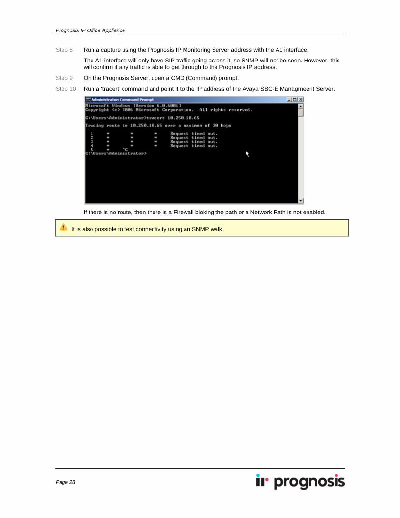
Step 9 On the Prognosis Server, open a CMD (Command) prompt.
Step 10 Run a ‘tracert’ command and point it to the IP address of the Avaya SBC-E Managmeent Server.
If there is no route, then there is a Firewall bloking the path or a Network Path is not enabled.
It is also possible to test connectivity using an SNMP walk.
Setup & User Guide
Page 29
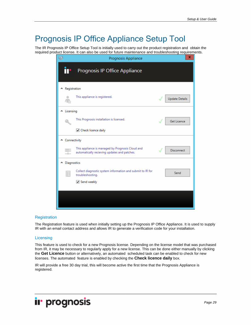
Prognosis IP Office Appliance Setup Tool The IR Prognosis IP Office Setup Tool is initially used to carry out the product registration and obtain the required product license. It can also be used for future maintenance and troubleshooting requirements.
Registration
The Registration feature is used when initially setting up the Prognosis IP Office Appliance. It is used to supply IR with an email contact address and allows IR to generate a verification code for your installation.
Licensing This feature is used to check for a new Prognosis license. Depending on the license model that was purchased from IR, it may be necessary to regularly apply for a new license. This can be done either manually by clicking the Get Licence button or alternatively, an automated scheduled task can be enabled to check for new licenses. The automated feature is enabled by checking the Check licence daily box.
IR will provide a free 30 day trial, this will become active the first time that the Prognosis Appliance is registered.
Prognosis IP Office Appliance
Page 30
Connectivity This feature is used to connect and disconnect from the Prognosis Cloud. When connected, the Prognosis Cloud can send patches and updates to your Appliance. It is recommended to stay connected at all times. However, you may opt out by disconnecting from the Prognosis Cloud. The Prognosis Cloud does not collect any information or data from your Appliance.
Diagnostics This feature is used to send diagnostic information to IR. This information is used by support staff to assist in locating and identifying any problems with the system. IR has a number of automatic scanning tools that will identify problems and alert support staff. Once issues have been identified and solutions are available, these will be automatically pushed down to Prognosis only if the Appliance is Connected to Prognosis Cloud.
Diagnostic Information The diagnostic information captured contains only local system data, error logs and Prognosis configuration data. The diagnostic information does not contain any personal information, company information or monitored data collected from your environment

Setup & User Guide
Page 31
Product Support An online forum is available that will provide support and further information for Prognosis IP Office Appliance. This forum can be accessed via the following URL:
https://online.prognosis.com/forum