Embed Size (px)
Citation preview
Technical Physics, Vol. 50, No. 4, 2005, pp. 503–507. Translated from Zhurnal Tekhnichesko
œ
Fiziki, Vol. 75, No. 4, 2005, pp. 114–117.Original Russian Text Copyright © 2005 by Davydov, Lebedev, Savkina, Volkova.
EXPERIMENTAL INSTRUMENTSAND TECHNIQUES
Setup Parameters Controlling the Growth Rate of Silicon Carbide Epitaxial Layers in a Vacuum
S. Yu. Davydov, A. A. Lebedev, N. S. Savkina, and A. A. VolkovaIoffe Physicotechnical Institute, Russian Academy of Sciences,
Politekhnicheskaya ul. 26, St. Petersburg, 194021 Russiae-mail: [email protected]
Received April 29, 2004
Abstract—An extension of the model suggested in [5] allows us to consider the influence of the growth cellgeometry, as well as temperature and pressure gradients, on the growth rate of SiC epitaxial layers in a vacuum.The experimental dependences of the substrate temperature on the current in an induction coil that are taken fordifferent positions of the cell relative to the inductor are discussed. © 2005 Pleiades Publishing, Inc.
INTRODUCTION
A variety of computational schemes have beendeveloped to describe gas-phase epitaxial growth ofsemiconductor films. However, all these schemes bearon transfer of film-forming atoms and moleculesthrough an inert gas filling the working space of thereactor [1–3]. Only the last section of review [4] isdevoted to film growth in a rarefied atmosphere (vac-uum). The scarcity of relevant publications is not agreat surprise. In an inert atmosphere, particle free pathλ is much shorter than typical geometric dimensions rand l of a growth cell (r is the inner radius of the cell,l is the distance between a vapor source and a sub-strate). This fact allows using the hydrodynamics equa-tions to describe transfer processes. In a rarefied atmo-sphere, conversely, λ @ r, l and stochastic processestaking place in the cell are described, as a rule, by theMonte Carlo method.
In [5], we suggested a simple model of the epitaxialgrowth of SiC layers. The model is based on the Hertz–Knudsen equation, which assumes the molecular fluxof silicon carbide, J, to be expressed by
(1)
where M is the SiC molecular weight, R is the universalgas constant, T is the temperature, and p =Bexp(−Q/RT) is the equilibrium SiC vapor pressure(Q is the heat of sublimation of SiC, B is a coefficient).
We also introduced an empiric coefficient of stick-ing of silicon carbide molecules to the substrate, α =Aexp(–Ea/RT), where Ea is the potential (activation)barrier that must be overcome by a molecule so that itwill adhere to the substrate and A is a preexponential.Then, growth rate G has the form
(2)
J Xp, X 2πMRT( ) 1/2– ,= =
GMρ-----Xpα ,=
1063-7842/05/5004- $26.00 0503
where ρ is the density of the growing SiC film.The experimental results were compared with
reduced growth rate g ≡ G/G0, where rate G corre-sponds to some temperature T and G0, to maximal tem-perature T0 used in a given experiment. Such a modelgives a good fit to the experimental data, as was shownin [5].
As follows from Eqs. (1) and (2), we ignored in [5]the fact that particle sticking to the cell walls and a tem-perature gradient may affect the particle flux. In theframework of our model, we will consider how thesefactors influence the growth rate.
EXPERIMENTAL SETUP
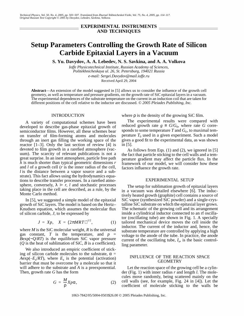
The setup for sublimation growth of epitaxial layersin a vacuum was detailed elsewhere [6]. The induc-tively heated growth (graphite) cell contains a source ofSiC vapor (synthesized SiC powder) and a single-crys-talline SiC substrate on which the epitaxial layer grows.The schematic of the growing cell and its arrangementinside a cylindrical inductor connected to an rf oscilla-tor (oscillating tube) are shown in Fig. 1. A speciallytailored mechanical device moves the cell inside theinductor. The current of the inductor and, hence, thesubstrate temperature are controlled by applying a highvoltage to the anode of the tube. In practice, the anodecurrent of the oscillating tube, Ia, is the basic control-ling parameter.
INFLUENCE OF THE REACTION SPACE GEOMETRY
Let the reaction space of the growing cell be a cylin-der (Fig. 1) with inner radius r and length l. The mole-cules move randomly, being scattered mainly on thecell walls (see, for example, Fig. 24 in [4]). Let thecoefficient of molecule sticking to the walls be
© 2005 Pleiades Publishing, Inc.
504
DAVYDOV
et al
.
expressed as = exp(– /RT), where is theenergy barrier that must be overcome by a SiC mole-cule so that it will adhere to the graphite wall. Then, adecrease in the particle flux due to wall scattering isdJ = –(J/r)dz, where axis z coincides with the axis ofthe cylinder. The flux arriving at the wall is (l) =J(0)[1 – exp(–l/r)], where J(0) is the initial flux (the fluxfrom the source, see (1)). The number of particles stick-ing to a unit wall area per unit time is , and (1 – )particles return to the mainstream. The flux arriving atthe substrate is J(0)[1 – (1 – exp(–l/r))]. The numberof particles sticking to a unit substrate area per unit timeequals
(3)
where
Thus, the growth rate can be expressed as
(4)
where G is given by (2).
For = 0 and l = 0, we have = G. For l = ∞, =G(1 – ); i.e., the growth rate decreases because of SiC
molecule sticking to the walls. For = 1, we have =Gexp(–l/r). Finally, when (l/r) @ 1, the growth ceases,since all the SiC molecules stick to the walls.
It is easy to show that, for (l/r) ! 1, F ≈ α[1 –(l/r)]; i.e., a decrease in the SiC molecular flux due to
sticking is vanishingly small. Consider now the limit(l/r) @ 1. For simplicity, we put = α, thereby assum-
α A Ea Ea
J
α J α J
α
J J 0( )F l/r( ), F l/r( ) α f l/r( ),= =
f l/r( ) 1 α 1 l/r–( )exp–[ ] .–=
G Gf l/r( ),=
α G Gα
α G
α
α
2
SiCs
l
1
r
SiCp
Fig. 1. Schematic of the cell for growing SiC epitaxial lay-ers in a vacuum and its arrangement inside the cylindricalinductor. 1, growth cell; 2, inductor; SiCp, silicon carbidepowder; and SiCs, substrate.
ing that the molecules equiprobably stick to the graph-ite walls of the reactor and to the substrate. By varyingsticking coefficient α, it is easy to check that function Fhas a maximum, Fmax ≈ 0.25, at α* ≈ 0.25. For l ≈ r, F ≈α[1 – (1 – e–1)]. Assuming again that = α, we getFmax ≈ 0.395 at α* ≈ 0.79.
Thus, a source of silicon carbide molecules in thegrowing cell should be placed at a distance l ≤ r fromthe substrate. It is such a geometry that is implementedin our setup: l = 7mm and r = 18 mm. Of course, theabove consideration greatly simplifies the real physicalpattern in the reactor (for example, processes, such asmultiple reflections of particles from the walls, scatter-ing by the substrate with subsequent transfer of themolecules to the walls, etc., are omitted). However, itmay provide a proper insight into the influence of thereaction space geometry on the growth rate of epitaxiallayers. Note that taking into account the SiC molecularflux toward the walls leads to straightforward renormal-ization of the growth rate (the appearance of additional
factor f(l/r); see Eq. (4)). When the value of is fittedto the experimental data according to the modeldescribed in [5], considering f(l/r) will change mainlythe value of dimensionless factor A. The temperaturedependence also becomes more complicated, becoming
(where ≡ /RT0) instead of
G ∝ T–1/2exp(–ω),
where ω ≡ (Q + Ea)/RT0).In this case, to determine additional model parame-
ters and , extra data points or any simplificationlike = α are needed.
INFLUENCE OF TEMPERATURE AND PRESSURE GRADIENTS
Now let us discuss the effect of a SiC vapor pressuregradient and a temperature gradient, ∆T = T(0) – T(l),in the cell on the growth rate (T(0) is the source temper-ature; T(l) is the substrate temperature; and l is, asabove, the source–substrate distance). To this end, wewill consider the problem of gas flow through a tube oflength l and radius r [7]. Unlike work [7], where it wasassumed that l/r @ 1, we take this ratio to be arbitrary(λ @ r, l, as before). Then, the flux can be approximated as
(5)
Here, p(0) and p(l) are the SiC vapor pressures abovethe source and substrate, respectively. For l/r @ 1,Eq. (5) transforms into the corresponding formula in
α α
G
G G 1 A ωa–( )exp 1 l/r–( )exp–[ ]– ,∝
ω Ea
Ea Aα
J 16/3( ) I
2πMR--------------------Ω, Ω p l( )
T l( )-------------- p 0( )
T 0( )---------------–
,≡=
I r/l l2r-----arctan
l2r----- l
2r----- 2r
l----- 1–arctan
+ .≈
TECHNICAL PHYSICS Vol. 50 No. 4 2005

SETUP PARAMETERS CONTROLLING THE GROWTH RATE 505
Table 1. Dependence of substrate temperature Tl on anode current Ia of the oscillating tube and on position z of the growthcell relative to the inductor
z, mmIa, A
1.00 1.25 1.50 1.75 2.00 2.25 2.50 2.75 3.00 3.25
0 900 1029 1109 1200 1294 1375 1470 1494 1594 1720
5 905 1032 1121 1208 1294 1396 1476 1501 1616 1750
10 909 1043 1127 1221 1306 1414 1482 1513 1627 1760
15 914 1064 1139 1234 1313 1402 1489 1537 1643 1765
20 914 1070 1142 1228 1319 1426 1494 1542 1643 1760
25 919 1093 1150 1228 1324 1426 1489 1548 1648 1755
30 924 1090 1153 1236 1326 1426 1494 1542 1643 1750
35 924 1093 1156 1234 1326 1426 1482 1537 1638 1735
37.5 924 1083 1156 1231 1324 1420 1470 1531 1632 1725
[7] and I ≈ π(r/2l).1 In the opposite limit, l/r ! 1, wehave I ≈ π(l/8r).
If the SiC vapor pressure were constant, i.e., thecondition p(0) ≈ p(l) ≈ p were satisfied, we would have
(6)
in other words, the temperature gradient would be theonly driving force of the process. Equation (5) implies,however, that, in the general case, the film grows if Ω >0, because the flux of SiC molecules will be directedfrom the source to the substrate just under this condi-tion. We then obtain from (5)
(7)
Putting p(0)/p(l) = αJ(0)/ (see (3) and (4)), weobtain
(8)
The right of inequality (8) exceeds unity by defini-tion (see (4)). Thus, the condition T(0)/T(l) > 1 is a nec-essary but not sufficient condition for the growth. Infact, the condition T(0)/T(l) >1 may be met even if ine-quality (8) has a reverse sign. In this case, Ω is negativeand the gas flows from the substrate to the source, i.e.,the substrate is etched.
Inequality (8) can be recast in the form
(9)
It follows from (9) that, for = 0, the layer growsat any positive temperature gradient ∆T, while at ≠ 0,∆T must be finite and increase with l/r. For example, at(l/r) ! 1, we have τ ≈ 2 (l/r); at l/r @ 1, τ ≈ 2 /(1 –
); and at l/r = 1, τ ≈ 1.26 /(1 – 0.63 ).
1 To derive an expression for flux J, the formula for gas amount Qderived in [7] should be divided by πr 2M.
Ω 1/2( ) ∆T /T 0( )( ) p/ T 0( )( );≈
T 0( )/T l( ) p 0( )/ p l( )( ).>
J
T 0( )/T l( ) f l/r( )( ) 1– .>
∆TT l( )---------- τ> 2α1 l/r–( )exp–
f l/r( )--------------------------------.≡
αα
α αα α α
TECHNICAL PHYSICS Vol. 50 No. 4 2005
Thus, the growth cell geometry meeting the weakinequality l/r ≤ 1 is also preferable for producing a tem-perature gradient. Clearly, sticking coefficient mustbe low in this case.
SUBSTRATE TEMPERATURE VERSUS SUBSTRATE POSITION RELATIVE
TO THE INDUCTION COIL
Table 1 demonstrates the experimental dependenceof substrate temperature Tl(r) on current Ia. The coordi-nate z = 0 corresponds to the lowest position of the sub-strate relative to the bottom of the inductor. The sub-strate is raised along axis z in 5-mm steps. Our aim is todeduce an analytical dependence for which purpose theresults of [8] are invoked. The temperature is assumedto be invariable, so that the time derivatives in the equa-tions are neglected. In addition, parameter κgas, which isthe thermal conductivity of argon in [8], is formally setequal to zero, since the growth proceeds in a vacuumand not in argon. Then, system of equations (1.1) in [8]is replaced by
(10)
where κ is the thermal conductivity of crystalline SiCand µ is the specific (per unit volume) thermal powergenerated by the inductor. Later on, subscript l is omit-ted. We are interested in temperature variation along thez direction, which is aligned with the setup axis. Then,assuming that κ is z-independent, we obtain
(11)
Let us introduce position parameter z* that isdefined by the relationship (dT/dz)z* = 0. At this posi-tion of the growth cell, the substrate temperaturereaches a maximum, Tmax, for given current Ia. Let thetemperature corresponding to z = 0 be denoted as Θ
α
div κgradT( ) µ,–=
d2T z( )dz2
---------------- µ/κ– a.–≡=

506 DAVYDOV et al.
Table 2. Substrate temperature Tl (°C) calculated as a function of position z (mm) of the substrate relative to the inductor fordifferent values of current Ia(A)
z 0 5 10 15 20 25 30 35 37.5
Ia = 1 A, z* = 35 mm, Θ = 900°C, Tmax = 924°C
900 906 912 916 920 922 924 924 924
900 905 909 914 914 919 924 924 924
Ia = 2 A, z* = 32.5 mm, Θ = 1294°C, Tmax = 1326°C
1294 1303 1311 1317 1322 1324 1326 1326 1325
1294 1294 1306 1313 1319 1324 1326 1326 1324
Ia = 3 A, z* = 25 mm, Θ = 1594°C, Tmax = 1648°C
1594 1613 1629 1639 1646 1648 1646 1639 1635
1594 1616 1627 1643 1643 1648 1643 1638 1632
Ia = 3.25 A, z* = 15 mm, Θ = 1720°C, Tmax = 1765°C
1720 1745 1760 1765 1760 1745 1720 1685 1664
1720 1750 1760 1765 1760 1755 1750 1735 1725
Tltheor
Tlexp
Tltheor
Tlexp
Tltheor
Tlexp
Tltheor
Tlexp
(obviously, Θ is a function of Ia). Then, we finally arriveat
(12)
Note that
(13)
Having determined the values of z*, Tmax, and Θfrom the experimental dependences of Tl on Ia (omit-
T Tmax Tmax Θ–( ) 1 z/z*–( )2.–=
a 2 Tmax Θ–( )/ z*( )2.=
4
8
12X, Y
01.0 1.5 2.5 3.53.02.0
Ia, A
1
2
Fig. 2. (1) X = a(Ia)/a(Ia = 1 A) and (2) Y = κ1/(Ia = 1 A)2κas a function of Ia.
Ia2
ted), we calculated substrate temperature Tl(z)(Table 1). For Ia = 1, 2, and 3 A, theory and experimentare in excellent agreement, while for Ia = 3.25 A, thecalculation underpredicts Tl at z > z*. The asymmetricrun of the curve Tl(z) at Ia = 3.25 A is noteworthy.
Figure 2 shows the ratio of coefficients a (see (13))in the form X = a(Ia)/a(Ia = 1 A) versus Ia (curve 1).Since a ∝ µ (see (11)) and specific thermal power µ isproportional to the current squared [8], Fig. 2 also
shows the dependence of ratio Y = κ1/(Ia = 1 A)2κ onIa (curve 2). Here, κ1 is the thermal conductivity at tem-perature Θ corresponding to Ia = 1 A and κ correspondsto temperatures Θ for Ia = 1.25, 1.5 A, etc. (Table 2).The temperature dependence of the thermal conductiv-ity for 6H-SiC were taken from [9].
In view of the fact that the approximation is crude,one can conclude that curves 1 and 2 are in fairly goodagreement in the range 1 ≤ Ia ≤ 3 A and diverge severely(by a factor of two) at Ia = 3.25 A. The reasons for sucha discrepancy still remain unclear.
ACKNOWLEDGMENTS
This work was partially supported by the RussianFoundation for Basic Research (project no. 03-02-16054b); INTAS (project no. 01-0603); and NATO SfP(project no. 978011).
Ia2
TECHNICAL PHYSICS Vol. 50 No. 4 2005
SETUP PARAMETERS CONTROLLING THE GROWTH RATE 507
REFERENCES1. A. I. Zhmakin, Yu. N. Makarov, D. Kh. Ofengeim, and
M. S. Ramm, in Problems of Mathematics Physics andApplied Mathematics (Ioffe Physicotechnical Institute,Russian Academy of Sciences, St. Petersburg, 2001),pp. 208–234 [in Russian].
2. M. Selder, L. Kadinsky, and F. Durst, in Problems ofMathematics Physics and Applied Mathematics (IoffePhysicotechnical Institute, Russian Academy of Sci-ences, St. Petersburg, 2001), pp. 235–252 [in Russian].
3. E. Kaldis and M. Piechotka, in Handbook of CrystalGrowth, Ed. by D. Hurle (Elsevier, Amsterdam, 1994),Vol. 2, pp. 615–656.
4. K. F. Jensen, in Handbook of Crystal Growth, Ed. byD. Hurle (Elsevier, Amsterdam, 1994), Vol. 3, pp. 543–599.
TECHNICAL PHYSICS Vol. 50 No. 4 2005
5. S. Yu. Davydov, A. A. Lebedev, N. S. Savkina, et al., Fiz.Tekh. Poluprovodn. (St. Petersburg) 38, 153 (2004)[Semiconductors 38, 150 (2004)].
6. N. S. Savkina, A. A. Levedev, D. V. Davydov, et al.,Mater. Sci. Eng., B 61–62, 50 (2000).
7. L. D. Landau and E. M. Lifshitz, Course of TheoreticalPhysics, Vol. 10: Physical Kinetics (Nauka, Moscow,1979; Pergamon, New York, 1981).
8. O. Klein and P. Philip, J. Cryst. Growth 247, 219 (2003).
9. O. Nilsson, H. Mehling, R. Horn, et al., High Temp.–High Press. 29, 73 (1997).
Translated by M. Astrov