Embed Size (px)
Citation preview
Journal of Computational Engineering and Physical Modeling 1-1 (2018) 68-82
CEPM is an open access journal under the CC BY license (http://creativecommons.org/licenses/BY/4.0/)
Contents lists available at CEPM
Journal of Computational Engineering and Physical Modeling
Journal homepage: http://www.jcepm.com/
Settlement Modelling of Raft Footing Founded on
Oferekpe/Abakaliki Shale in South East Region of Nigeria
A. B. Salahudeen1*
and S. Aghayan2
1. Ph.D., Samaru College of Agriculture, Division of Agricultural Colleges, Ahmadu Bello University, Zaria,
Nigeria
2. Ph.D. Candidate, Department of Mining and Metallurgical Engineering, Amirkabir University, Tehran, Iran
Corresponding author: [email protected]
http://dx.doi.org/10.22115/CEPM.2018.116754.1009
ARTICLE INFO
ABSTRACT
Article history:
Received: 25 January 2018
Revised: 11 March 2018
Accepted: 31 March 2018
In engineering practice, settlement of foundations are
experimentally determined or numerically modelled based on
conventional saturated soil mechanics principles. The study
area, Oferekpe in Abakaliki LGA of Ebonyi State, South
Eastern Region of Nigeria is characterised with sedimentary
formations highly susceptible to compression under applied
load. The study was aimed at evaluating raft footing settlement
by both analytical and numerical modelling methods and
determine the effect of raft thickness on settlement. Standard
penetration test (SPT) data was used to correlate soil properties
that were used together with laboratory results to obtain the
input parameters used for the prediction of settlement. Four
footing embedment depths of 1.5, 3.0, 4.5 and 6.0 m with
applied foundation pressures of 50, 100, 200, 300, 400 and
500kN/m2 were considered using a raft footing dimension of 20
x 20 m2 at varying thickness of 0.5, 0.75 and 1.0 m. The
numerical modelling finite element application package used
was Plaxis 3D. For applied pressure of 100 kN/m2 and at
footing embedment depths of 1.5, 3.0, 4.5 and 6.0 m, settlement
values of (21.89, 11.51, 9.04 and 6.52), (19.70, 8.60, 6.41 and
4.39), (25.62, 14.88, 12.05 and 9.27) and (25.20, 11.59, 5.57
and 2.58) were respectively predicted by the elastic, semi-
empirical, empirical and finite element methods. It was
observed that the elastic method of predicting foundation
settlement proposed by Steinbrenner yielded a very close range
results generally to those predicted by finite element method. It
was generally observed that thickness of raft footing has no significant effect on the predicted settlement.
Keywords:
Raft foundation,
Settlement prediction,
Numerical modelling,
Standard penetration test,
Plaxis 3D.

A. B. Salahudeen and S. Aghayan/ Journal of Computational Engineering and Physical Modeling 1-1 (2018) 68-82 69
1. Introduction
A raft foundation is mostly used where the site and load conditions could cause significant
differential and/or total settlement between individual spread footings but where conditions are
not so poor to warrant deep footing. For buildings with substantial overturning moments, which
is common in regions of high seismicity or because of irregularities of the superstructure loading,
a mat foundation is commonly used to distribute the bearing pressure over a large surface area
and/or to resist substantial uplift forces that could develop. Another common use of mat footing
is when individual pad footings would be large and close to each other. Likewise, in a situation
where several grade beam ties among footings are required, it may not be economical to excavate
and form individual spread footings as compared to constructing a single raft foundation [1]. It is
also suitable for ground containing pockets of loose and soft soils [2]. Mats may be supported by
piles, which help reduce the settlement of a structure built over highly compressible soil [3].
Where the water table is high, mats are often placed over piles to control buoyancy [2].
Numerical modelling is a powerful mathematical tool that makes it possible to solve complex
engineering problems. The constitutive behaviour of soils can be successfully modelled with
numerical analyses using some basic soil properties as input data. The finite element method is a
modelling code in which continuous media is divided into finite elements with different
geometries. It makes it possible to idealize the material behaviour of the soil, which is non-linear
with plastic deformations and is stress-path dependent, in a more realistic manner [4]. There are
several methods in use to predict foundations settlement in granular soils. One common
assumption in these methods represent sand as possessing elastic strains only, and thereby plastic
deformations are not directly taken into considerations [5-6]. In reality, the constitutive
behaviour of soils governs the response of the soil material under the foundation and therefore
influences and seriously determines the prediction of bearing capacity and settlement [7].
The objective of all site exploration is to obtain data that will adequately quantify the variability
of the geotechnical properties of the site. Site investigation and estimation of soil properties are
essential parts of a geotechnical design process. Geotechnical engineers are tasked with the
determination of the average values and variability of the site soil properties [8]. In situ testing is
very important in geotechnical engineering, since simple laboratory tests may not be reliable
while more sophisticated laboratory testing can be time consuming and costly [9]. Standard
Penetration Test (SPT), which was used in this study, is an in situ testing methods that is used to
identify soil type and stratigraphy along with being a relative measure of strength. The results of
the test can be indirectly used to estimate the bearing capacity and settlement characteristics of
the soil and could be used to determine the type of foundation required to effectively carry
structural load without bearing capacity failure and/or excessive settlement.
Some Nigerian soils are problematic and create serious threats and adverse effects to foundations
of structures and the structures themselves. These soil problems include excessive settlement,
tilting and collapse of structures [5]. Finite element technique that gives a better approximate
values of footing settlement is needed for reliable prediction of foundation settlement. The
70 A. B. Salahudeen and S. Aghayan / Journal of Computational Engineering and Physical Modeling 1-1 (2018) 68-82
prediction in this study was based on SPT results, being the most common and economical
geotechnical in situ test used in Nigeria. This study used SPT results as input data in foundation
settlement estimation using analytical models and Plaxis 3D package. The specific objectives of
this study were to predict raft settlement from measured penetration resistance in terms of the
SPT N-value at varying depths and applied footing pressure, to evaluate analytical equations
used settlement prediction that are based on different constitutive models, to model foundation
settlement numerically using PLAXIS 3D software, compare the results of the analytical
methods with those of numerical analysis and investigate the effect of raft thickness on
settlement.
2. Location and geology of the study area
The study area is Oferekpe in Abakaliki Local Government Area of Ebonyi State, South Eastern
Region of Nigeria. Nigeria is situated entirely within the tropical zone and has a total land mass
of about 924,000km2 [10]. The coastal areas are usually covered by soft rocks which are
prominent along the Niger Delta, Niger Benue trough and Lake Chad Basin. The lowland areas
are composed of sedimentary rock and cover the Sokoto plains, Chad Basin, Niger-Benue
trough, western areas of Nigeria, south-eastern Nigeria and coastal margins and swamps [11].
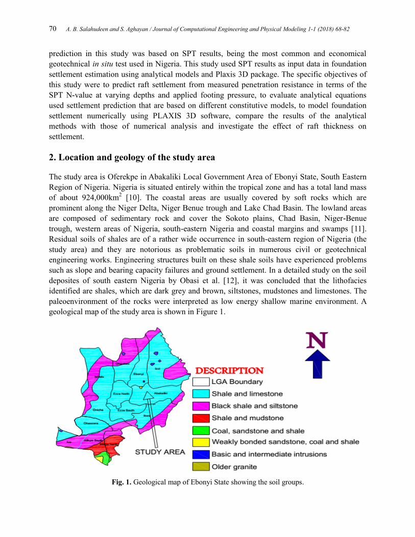
Residual soils of shales are of a rather wide occurrence in south-eastern region of Nigeria (the
study area) and they are notorious as problematic soils in numerous civil or geotechnical
engineering works. Engineering structures built on these shale soils have experienced problems
such as slope and bearing capacity failures and ground settlement. In a detailed study on the soil
deposites of south eastern Nigeria by Obasi et al. [12], it was concluded that the lithofacies
identified are shales, which are dark grey and brown, siltstones, mudstones and limestones. The
paleoenvironment of the rocks were interpreted as low energy shallow marine environment. A
geological map of the study area is shown in Figure 1.
Fig. 1. Geological map of Ebonyi State showing the soil groups.

A. B. Salahudeen and S. Aghayan/ Journal of Computational Engineering and Physical Modeling 1-1 (2018) 68-82 71
3. Research methodology
This study made use of Standard Penetration Test (SPT) data conducted at four footing
embedment depths of 1.5, 3.0. 4.5 and 6.0 m. Computation of foundation settlement were done at
raft footing thickness of 0.5, 0.75 and 1.0 m which are random choice and applied foundation
pressures of 50, 100, 200, 300, 400 and 500kN/m2 which represent the applied structural loads
on the foundation. A raft footing with plan dimension of 20 m x 20 m was randomly considered
for the study.
3.1. Analytical methods
Based on analytical methods, foundation settlement estimations were performed using three
common settlement prediction models to compare with the results of numerical analysis as
shown in Table 1. The models are elastic, semi-empirical and empirical in nature which were
proposed by Steinbrenner [13], Terzaghi et al. [14] and Schultze and Sherif [15] respectively.
Various analytical methods available at the present time to calculate the elastic settlement can be
summarised into three different categories [16]. The first category is the empirical methods
which are methodologies based on in situ measured settlement of structures and full scale
prototypes. These methods are empirical in nature and are correlated with the results of the
standard in situ tests such as the SPT. The second category is the semi-empirical methods which
are based on a combination of field observations and some theoretical studies. Lastly, the elastic
methods, which are based on theoretical relationships derived from the theory of elasticity.
Based on elastic theory, Steinbrenner [13] computed the settlements at any depth below the
corner of a uniformly loaded rectangular footing located on the horizontal surface of a semi-
infinite homogeneous isotropic elastic mass of constant elastic properties. He assumed that the
settlement at the corner on a soil layer of depth H was equal to the settlement of the surface point
minus the settlement of the point at depth H. Terzaghi et al. [14] made numerous comparisons
between the results of settlement observations on actual footings and estimates based on other
procedures using several hundred reliable records of settlements of structures on sand which
were used in statistical studies resulting in more reliable semi-empirical methods for estimating
the elastic settlements. Based on the results of a study of the observed settlements at 48 sites,
Schultze and Sherif [15] developed an empirical method to estimate the settlement of shallow
foundations on sand using SPT results. The analytical models used in this study were considered
based on their recommendations in literatures.
Table 1.
Analytical models for settlement prediction
Method
category
Expression Definitions Reference
Corrected
N-value
(N60)
𝑁60 =𝑁ƞ𝐻ƞ𝐵ƞ𝑆ƞ𝑅
60
N60=Corrected standard
penetration number for field
conditions
N=Measured penetration number
(N-value)
ȠH=Hammer efficiency (%)
ȠB = Correction for borehole
diameter
ȠS=Sampler correction
ȠR = Correction for rod length
[17-18]

72 A. B. Salahudeen and S. Aghayan / Journal of Computational Engineering and Physical Modeling 1-1 (2018) 68-82
Elastic 𝑆 =
𝑞𝐵
𝐸� 1 − 𝜇2 𝐹1 + 1 − 𝜇 − 2𝜇2 𝐹2
Se = Elastic settlement (mm)
q = Applied foundation pressure
(kN/m2)
B = Width of foundation (m)
E=Elastic modulus of soil
(kN/m2)
𝜇 = Poisson’s ratio of soil
F1 and F2 are further expressions
that depend on the length and
depth factors
[13]
Semi-
Empirical 𝑆𝑒= 𝑍1
1.7
Ń601.4 𝑞
𝑍1 = 𝐵0.75
Z1 = Represents the depth of
influence below which the
vertical strains under the
foundation are negligible
[14]
Empirical
𝑆𝑒=
𝑓𝑞�𝐵
𝑁0.87 1 +0.4𝐷𝑓
𝐵
f = influence factor depending
upon the foundation geometry
[15]
3.2. Numerical modelling
On the other hand, numerical analysis of foundation settlement was performed using 3-D non-
linear finite element analysis software, Plaxis, a finite element code. The input data in Plaxis are
from the processed SPT results. The Soil properties and material properties of the raft footing and
wall (to prevent collapse of the excavated surface) used for numerical analysis and general
computations are presented in Tables 2 and 3 respectively. The software portfolio includes
simulation of soil and soil-structure interaction. Soil layers were defined by means of boreholes
which is a method specific with Plaxis 3D. Structures were defined in horizontal work planes.
Details on this topic can be found in Plaxis 3D Manual [19].
Table 2.
Soil properties for numerical analysis and general computations
Parameter Unit Values according to depth of standard
penetration test boring
1.5 m 3.0 m 4.5 m 6.0 m
SPT N-value (N) - 26 47 58 76
Corrected N-value (N60) - 23.21 41.95 51.77 67.83
Bulk Unit Weight kN/m3 20.51 19.82 21.84 22.34
Friction angle Degree 33.77 38.73 41.18 44.96
Dilatancy angle Degree 0.0 0.0 0.0 0.0
Cohesion kN/m2 26.00 24.00 23.00 29.00
Young’s modulus kN/m2 11603 20974 25883 33915
Poisson’s ratio - 0.232 0.306 0.343 0.399
Soil model - Mohr-Coulomb
Soil behaviour - Drained
A. B. Salahudeen and S. Aghayan/ Journal of Computational Engineering and Physical Modeling 1-1 (2018) 68-82 73
Table 3.
Material properties for raft and wall above raft footing in numerical analysis
Parameter Unit Raft Wall
Unit weight kN/m3 24 24
Thickness m Varied (0.5, 0.75, 1.0) 0.23
Young’s modulus kN/m2 2.74 x 10
7 2.74 x 10
7
Poisson’s ratio - 0.2 0.2
Material behaviour - Linear (Isotropic)
3.3. Standard penetration test
The standard penetration test (SPT) was conducted in accordance with ASTM D-1586-99 [20]
and [21]. The N-value was corrected to an average energy ratio of 60% (N60) before used to
correlate soil properties. SPT was conducted at four depth at intervals of 1.5 m. It should be
noted that this study is focused on the use of SPT data to generate soil properties that are used for
the settlement predictions. It is not an objective of this study to discuss the Pedogenesis of the
soil type which is shale in this case. All soil properties are based on the SPT resistance of the
soil. However, a detailed description of the geology of the study area is herein presented.
4. Results and discussion
4.1. Soil conditions
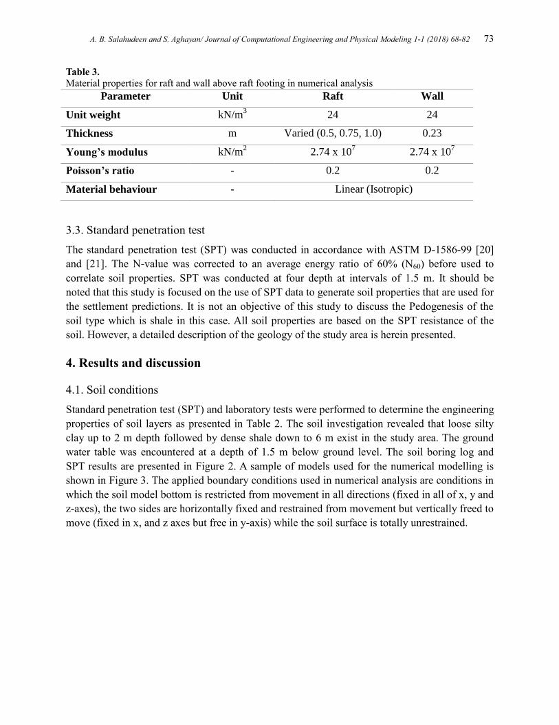
Standard penetration test (SPT) and laboratory tests were performed to determine the engineering
properties of soil layers as presented in Table 2. The soil investigation revealed that loose silty
clay up to 2 m depth followed by dense shale down to 6 m exist in the study area. The ground
water table was encountered at a depth of 1.5 m below ground level. The soil boring log and
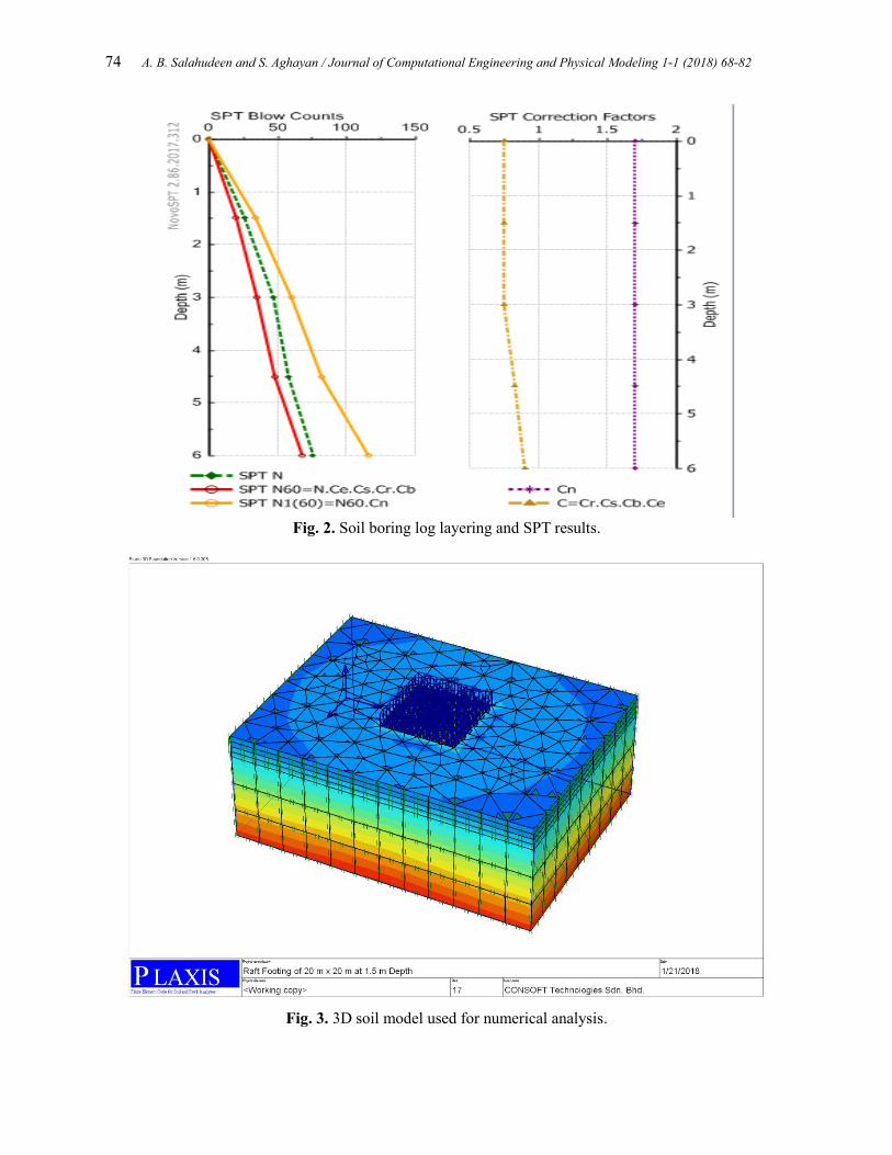
SPT results are presented in Figure 2. A sample of models used for the numerical modelling is
shown in Figure 3. The applied boundary conditions used in numerical analysis are conditions in
which the soil model bottom is restricted from movement in all directions (fixed in all of x, y and
z-axes), the two sides are horizontally fixed and restrained from movement but vertically freed to
move (fixed in x, and z axes but free in y-axis) while the soil surface is totally unrestrained.
74 A. B. Salahudeen and S. Aghayan / Journal of Computational Engineering and Physical Modeling 1-1 (2018) 68-82
Fig. 2. Soil boring log layering and SPT results.
Fig. 3. 3D soil model used for numerical analysis.

A. B. Salahudeen and S. Aghayan/ Journal of Computational Engineering and Physical Modeling 1-1 (2018) 68-82 75
4.2. Settlement of raft foundation
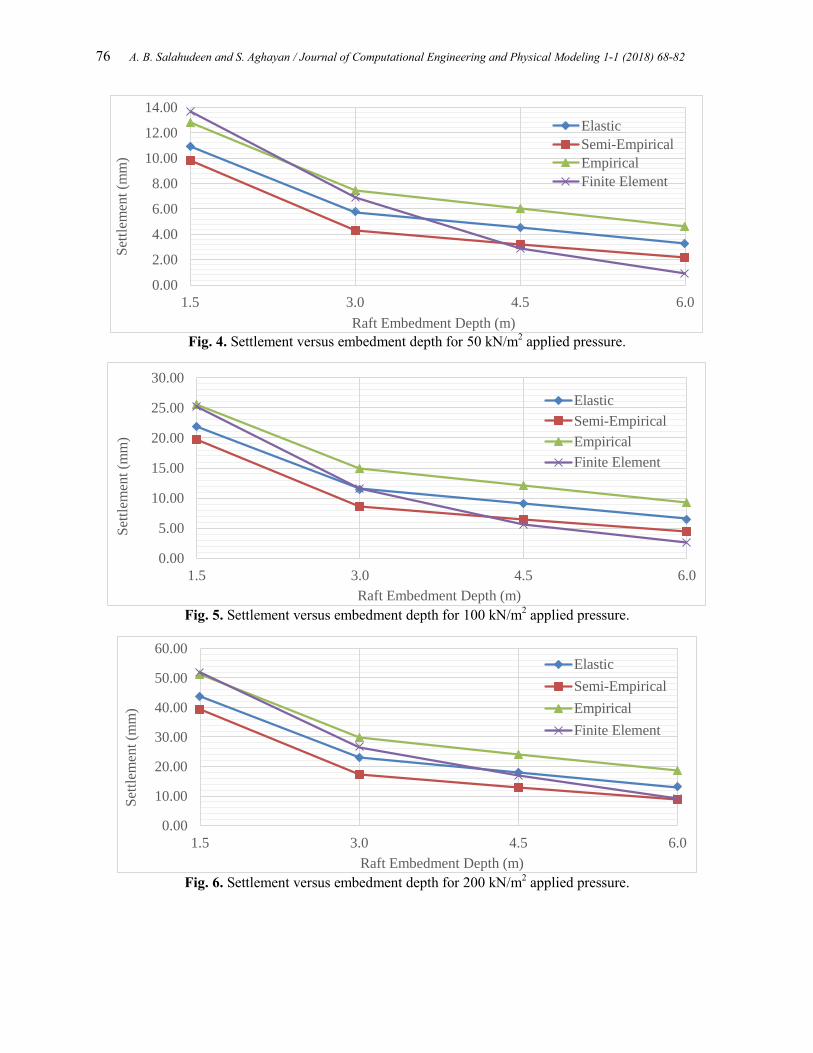
The elastic settlements of raft versus boring depths are shown in Figures 4 – 9 for applied
pressures of 50, 100, 200, 300, 400 and 500 kN/m2 respectively at a constant raft thickness of 0.5
m. The figures show three analytical models (one for each of empirical, semi-empirical and
elastic methods) commonly used in computing elastic settlement of foundations and results of
finite element in numerical modelling using Plaxis 3D Foundation software which was used as
yardstick to measure the performance of the analytical methods. It should be noted that
numerical modelling has been confirmed to give an acceptable prediction of footing settlement in
the literatures. For applied pressure of 100 kN/m2 and at footing embedment depths of 1.5, 3.0,
4.5 and 6.0 m, settlement values of (21.89, 11.51, 9.04 and 6.52), (19.70, 8.60, 6.41 and 4.39),
(25.62, 14.88, 12.05 and 9.27) and (25.20, 11.59, 5.57 and 2.58) were respectively predicted by
the elastic, semi-empirical, empirical and finite element methods. From the observed trends, it is
obvious that the elastic method of predicting foundation settlement proposed by Steinbrenner
[13] yielded a very close range results generally to those predicted by finite element method
followed by the empirical method proposed by Schultze and Sherif ([14] and lastly by the semi-
empirical method proposed by Terzaghi et al. [15]. It can also be observed that it is difficult to
reach conclusion on the actual settlement values based on the maximum allowable limiting
values recommended by codes of practices due to the wide range of results produced by different
analytical methods. This is exactly why numerical modelling, as an emerging technology is very
vital and useful for predicting the actual and exact value of foundation settlement in sites were
physical measurement is not viable owing to the consideration of the actual soil constitutive
model in numerical analysis.
The observed trend is in line with observations of Rasin [22]. A comparison carried out by
Shahin et al. [23] based on field measurement and artificial neural networks (ANN) results of
three settlement prediction methods rated the Schltze and Sherif [15] method as the best for
estimating shallow foundation settlements. Ahmed [24] rated the semi-empirical method
proposed by Schmertmann et al. [25] as best among others. In a study carried out by Salahudeen
et al. [6] in the South-East region of Nigeria based on 425 case history and 3825 database, a
comparison of fifteen empirical/analytical methods was made and methods proposed by
Schmertmann et al. [25], Burland and Burbidge [26], Terzaghi et al. [14], Mayne and Poulos
[27] as well as Canadian Foundation engineering Manual (CFEM) [28] were considered to give
good estimations of foundation settlement. This could be due to consideration of several
conditions that applied in all types of soils in the development of these models. In a detailed
study by Raymond [29], Salahudeen and Sadeeq [30-31] and Salahudeen [10] comparing several
elastic methods of predicting foundation settlement rated the method proposed by Steinbrenner
[13] as best of all elastic methods. This could be due to the fact that Steinbrenner’s method
considered all the footing dimensions in addition to several other considerations which is rarely
done in most other methods.
76 A. B. Salahudeen and S. Aghayan / Journal of Computational Engineering and Physical Modeling 1-1 (2018) 68-82
Fig. 4. Settlement versus embedment depth for 50 kN/m
2 applied pressure.
Fig. 5. Settlement versus embedment depth for 100 kN/m
2 applied pressure.
Fig. 6. Settlement versus embedment depth for 200 kN/m
2 applied pressure.
0.00
2.00
4.00
6.00
8.00
10.00
12.00
14.00
1.5 3.0 4.5 6.0
Set
tlem
ent
(mm
)
Raft Embedment Depth (m)
Elastic
Semi-Empirical
Empirical
Finite Element
0.00
5.00
10.00
15.00
20.00
25.00
30.00
1.5 3.0 4.5 6.0
Set
tlem
ent
(mm
)
Raft Embedment Depth (m)
Elastic
Semi-Empirical
Empirical
Finite Element
0.00
10.00
20.00
30.00
40.00
50.00
60.00
1.5 3.0 4.5 6.0
Set
tlem
ent
(mm
)
Raft Embedment Depth (m)
Elastic
Semi-Empirical
Empirical
Finite Element

A. B. Salahudeen and S. Aghayan/ Journal of Computational Engineering and Physical Modeling 1-1 (2018) 68-82 77
Fig. 7. Settlement versus embedment depth for 300 kN/m
2 applied pressure.
Fig. 8. Settlement versus embedment depth for 400 kN/m
2 applied pressure.
Fig. 9. Settlement versus embedment depth for 500 kN/m2 applied pressure.
0.00
10.00
20.00
30.00
40.00
50.00
60.00
70.00
80.00
1.5 3.0 4.5 6.0
Set
tlem
ent
(mm
)
Raft Embedment Depth (m)
Elastic
Semi-Empirical
Empirical
Finite Element
0.00
20.00
40.00
60.00
80.00
100.00
120.00
1.5 3.0 4.5 6.0
Set
tlem
ent
(mm
)
Raft Embedment Depth (m)
Elastic
Semi-Empirical
Empirical
Finite Element
0.00
20.00
40.00
60.00
80.00
100.00
120.00
140.00
1.5 3.0 4.5 6.0
Set
tlem
ent
(mm
)
Raft Embedment Depth (m)
Elastic
Semi-Empirical
Empirical
Finite Element
78 A. B. Salahudeen and S. Aghayan / Journal of Computational Engineering and Physical Modeling 1-1 (2018) 68-82
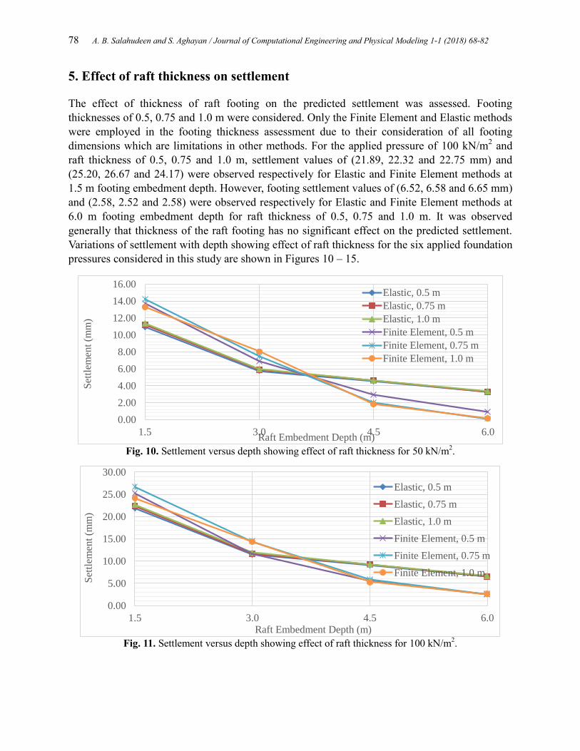
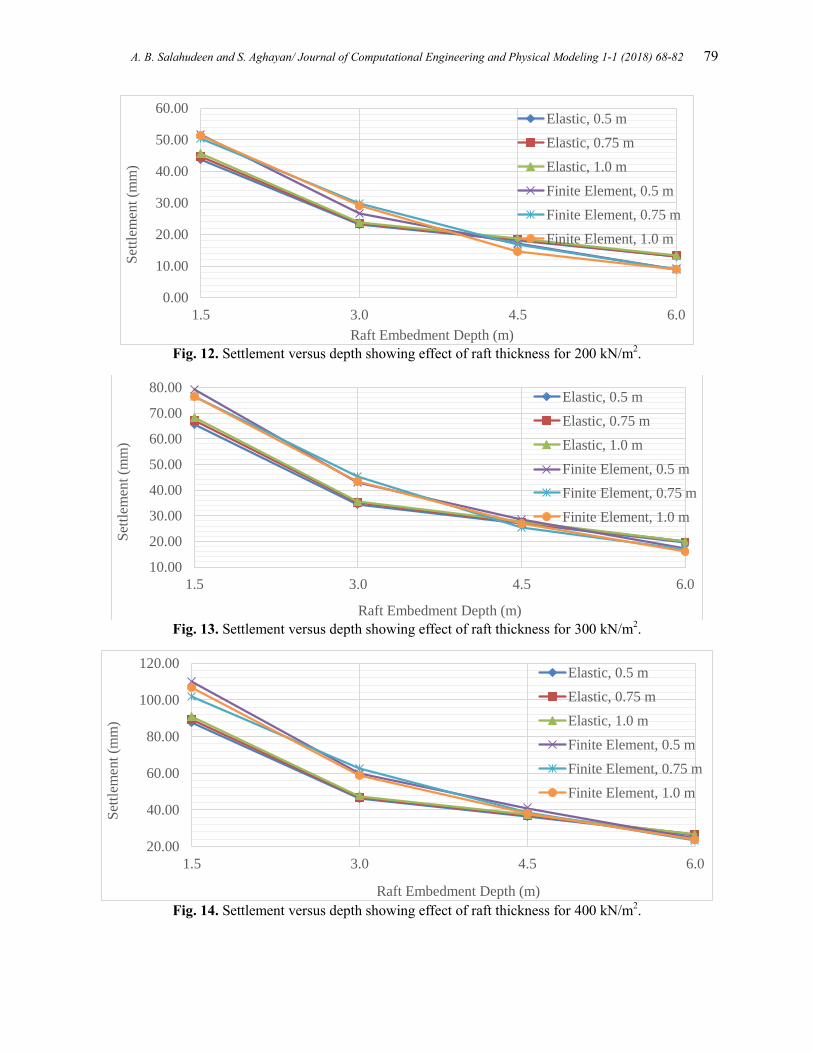
5. Effect of raft thickness on settlement
The effect of thickness of raft footing on the predicted settlement was assessed. Footing
thicknesses of 0.5, 0.75 and 1.0 m were considered. Only the Finite Element and Elastic methods
were employed in the footing thickness assessment due to their consideration of all footing
dimensions which are limitations in other methods. For the applied pressure of 100 kN/m2 and
raft thickness of 0.5, 0.75 and 1.0 m, settlement values of (21.89, 22.32 and 22.75 mm) and
(25.20, 26.67 and 24.17) were observed respectively for Elastic and Finite Element methods at
1.5 m footing embedment depth. However, footing settlement values of (6.52, 6.58 and 6.65 mm)
and (2.58, 2.52 and 2.58) were observed respectively for Elastic and Finite Element methods at
6.0 m footing embedment depth for raft thickness of 0.5, 0.75 and 1.0 m. It was observed
generally that thickness of the raft footing has no significant effect on the predicted settlement.
Variations of settlement with depth showing effect of raft thickness for the six applied foundation
pressures considered in this study are shown in Figures 10 – 15.
Fig. 10. Settlement versus depth showing effect of raft thickness for 50 kN/m
2.
Fig. 11. Settlement versus depth showing effect of raft thickness for 100 kN/m
2.
0.00
2.00
4.00
6.00
8.00
10.00
12.00
14.00
16.00
1.5 3.0 4.5 6.0
Set
tlem
ent
(mm
)
Raft Embedment Depth (m)
Elastic, 0.5 m
Elastic, 0.75 m
Elastic, 1.0 m
Finite Element, 0.5 m
Finite Element, 0.75 m
Finite Element, 1.0 m
0.00
5.00
10.00
15.00
20.00
25.00
30.00
1.5 3.0 4.5 6.0
Set
tlem
ent
(mm
)
Raft Embedment Depth (m)
Elastic, 0.5 m
Elastic, 0.75 m
Elastic, 1.0 m
Finite Element, 0.5 m
Finite Element, 0.75 m
Finite Element, 1.0 m
A. B. Salahudeen and S. Aghayan/ Journal of Computational Engineering and Physical Modeling 1-1 (2018) 68-82 79
Fig. 12. Settlement versus depth showing effect of raft thickness for 200 kN/m
2.
Fig. 13. Settlement versus depth showing effect of raft thickness for 300 kN/m
2.
Fig. 14. Settlement versus depth showing effect of raft thickness for 400 kN/m
2.
0.00
10.00
20.00
30.00
40.00
50.00
60.00
1.5 3.0 4.5 6.0
Set
tlem
ent
(mm
)
Raft Embedment Depth (m)
Elastic, 0.5 m
Elastic, 0.75 m
Elastic, 1.0 m
Finite Element, 0.5 m
Finite Element, 0.75 m
Finite Element, 1.0 m
10.00
20.00
30.00
40.00
50.00
60.00
70.00
80.00
1.5 3.0 4.5 6.0
Set
tlem
ent
(mm
)
Raft Embedment Depth (m)
Elastic, 0.5 m
Elastic, 0.75 m
Elastic, 1.0 m
Finite Element, 0.5 m
Finite Element, 0.75 m
Finite Element, 1.0 m
20.00
40.00
60.00
80.00
100.00
120.00
1.5 3.0 4.5 6.0
Set
tlem
ent
(mm
)
Raft Embedment Depth (m)
Elastic, 0.5 m
Elastic, 0.75 m
Elastic, 1.0 m
Finite Element, 0.5 m
Finite Element, 0.75 m
Finite Element, 1.0 m

80 A. B. Salahudeen and S. Aghayan / Journal of Computational Engineering and Physical Modeling 1-1 (2018) 68-82
Fig. 15. Settlement versus depth showing effect of raft thickness for 500 kN/m
2.
6. Conclusion
The study carried out made use of SPT N-values and laboratory results as input data in analytical
and numerical models for the prediction of foundation settlement at Oferekpe in Abakaliki Local
Government of Ebonyi State, Federal Republic of Nigeria. Raft footing plan of 20 m x 20 m at
varied thickness of 0.5, 0.75 and 1.0 m and applied pressures of 50, 100, 200, 300, 400 and
500kN/m2 at foundation embedment depths of 1.5, 3.0, 4.5 and 6.0 m were adopted. Foundation
settlement estimations were performed using three very common settlement prediction models to
compare with the results of numerical analysis based on finite element method. The models are
elastic, semi-empirical and empirical in nature which were proposed Steinbrenner, Terzaghi et al.
and Schultze and Sherif respectivlyBased on the results obtained, the following conclusions can
be made.
1. From the observed trends, it is obvious that the elastic method of predicting foundation
settlement proposed by Steinbrenner gave a very close range results generally to those
predicted by finite element method followed by the empirical method proposed by
Schultze and Sherif and lastly by the semi-empirical method proposed by Terzaghi et al.
2. It was also observed that it is difficult to reach conclusion on the actual settlement values
based on the maximum allowable limiting values recommended by codes of practices due
to the wide range of results produced by different analytical methods.
3. It was generally observed that thickness of the raft footing has no significant effect on the
predicted settlement.
Acknowledgement
The assistance of the Management of YAROSON PARTNERSHIP, Kaduna, Nigeria that
provided the standard penetration test data used for this study is gratefully acknowledged.
20.00
40.00
60.00
80.00
100.00
120.00
140.00
1.5 3.0 4.5 6.0
Set
tlem
ent
(mm
)
Raft Embedment Depth (m)
Elastic, 0.5 m
Elastic, 0.75 m
Elastic, 1.0 m
Finite Element, 0.5 m
Finite Element, 0.75 m
Finite Element, 1.0 m
A. B. Salahudeen and S. Aghayan/ Journal of Computational Engineering and Physical Modeling 1-1 (2018) 68-82 81
References
[1] Klemencic, R., McFarlane, I.S., Hawkins, N. M. And Nikolaou, S. (2012) “Seismic design of
reinforced concrete mat foundations”. NEHRP Seismic Design Technical Brief, No. 7 NIST GCR
12-917-22.
[2] Hussein, H. M. A. (2011). “Effects of Flexural Rigidity and Soil Modulus on the Linear Static
Analysis of Raft Foundations.” Journal of Babylon university, Pure and Applied Science, Vol. 19,
No. 2, pp. 740-752.
[3] Chaudhary, M. T. A. (2007). FEM modelling of a large piled raft for settlement control in weak rock.
Engineering Structures, Vol. 29, No. 11, pp. 2901-2907.
[4] Ornek, M., Demir, A., Laman, M. and Yildiz, A. (2012). “Numerical analysis of circular footings on
natural clay stabilized with a granular fill”. Acta geotechnica slovenica, No. 1, 61-75.
[5] Salahudeen A. B.,Eberemu A. O., Ijimdiya T. S. and Osinubi K. J. (2016a). Prediction of Bearing
Capacity and Settlement of Foundations in the South-East of Nigeria. Proceedings of Material
Science and Technology Society of Nigeria (MSN) Conference, Kaduna State chapter, NARICT,
Zaria, pp. 15 – 21.
[6] Salahudeen, A. B., Eberemu, A. O., Ijimdiya, T. S. and Osinubi K. J. (2017). Empirical and numerical
prediction of settlement and bearing capacity of foundations from SPT data in North-West region
of Nigeria. Nigerian Journal of Engineering (NJE), Vol. 23 No.2, Pp. 31-41.
[7] Johnson, K., Christensen, M., Sivakugan, N. and Karunasena, W. (2015). Simulating the Response of
Shallow Foundations using Finite Element Modelling. Australian Civil Engineering Transactions,
pp. 1 - 6.
[8] Salahudeen, A. B., Ijimdiya, T. S.,Eberemu, A. O. and Osinubi, K. J. (2016b). Prediction of bearing
capacity and settlement of foundations using standard penetration data in the South-South geo-
political zone of Nigeria. Proceedings of International conference on Construction Summit,
Nigerian Building and Road Research Institute (NBRRI), Abuja, Nigeria, pp. 349 – 368.
[9] Al-Jabban, M. J. W. (2013). “Estimation of Standard Penetration Test (SPT) of Hilla City-Iraq by
Using GPS Coordination”. Jordan Journal of Civil Engineering (JJCE), Volume 7, No. 2, 133-145.
[10] Ola, S.A. (1983).Tropical Soils of Nigeria in Engineering Practice. A.A, Balkema/Rotterdam
Edition, Netherlands.
[11] Salahudeen, A. B. (2017). “Prediction of foundation settlement based on standard penetration test
results using empirical and numerical techniques.” Unpublished PhD thesis, Department of Civil
Engineering, Ahmadu Bello University, Zaria, Nigeria. Pp 70 – 77.
[12] Obasi, A. I., Okoro, A. U., Nweke, O. M. and Chukwu, A. (2013). Lithofacies and paleo depositional
environment of the rocks of Nkpuma-Akpatakpa, Izzi, Southeast Nigeria. African Journal of
Environmental Science and Technology, Vol. 7, No. 10, pp. 967 – 975.
[13] Steinbrenner, G. (1934). Der Zeitliche Verlauf einer Grundwasserabsenkung. Wasserwirtsch.
Tecknik, volume 4, pp. 27-33.
[14] Terzaghi, K., Peck, R.B. &Mesri, G. (1996). Soil Mechanics in Engineering Practice. (Third edition).
John Wiley & Sons, New York, 549.
[15] Schultze, E. and G. Sherif (1973). “Prediction of settlements fromevaluated settlement observations
for sand”. In Proc., 8th Int.Conf. On Soil Mech. & Found. Engrg., Volume 1(3), pp.225–230.
[16] Das, B. M. (2014). “Elastic settlement of shallow foundations on granular soil: a critical review.” A
research report, California State University, Sacramento Henderson, Nevada, U.S.A.
[17] Seed, H. B., Tokimatsu, K., Harder, L. F., and Chung, R. M. (1985). “Influence of SPT Procedures in
Soil Liquefaction Resistance Evaluations,” Journal of Geotechnical Engineering, ASCE, Vol. 111,
No. 12, pp. 1425 –1445.

82 A. B. Salahudeen and S. Aghayan / Journal of Computational Engineering and Physical Modeling 1-1 (2018) 68-82
[18] Skempton, A.W. (1986). “Standard Penetration Test Procedures and the Effect in Sands of
Overburden Pressure, Relative Density, Particle Size, Aging and Over-Consolidation.”
Geotechnique, 36 No. 3, 425-447.
[19] PLAXIS 3D manual (2010). Plaxis 3D-Version 1.6 edited by Brinkgreve R. B. J. Delft University of
Technology and PLAXIS b.v., The Netherland.
[20] American Society for Testing and Materials (2001). “Standard Test Method for Penetration Test and
Split Barrel Sampling of Soils (D1586)”. ASTM International, West Conshohocken.
[21] Bowles, J.E. (1996). Foundation Analysis and Design, 5thEdition., McGraw-Hill, USA.
[22] Rasin, D. (2009). “Observed and predicted settlement of shallow foundation.” 2nd
International
Conference on New Developments in Soil Mechanics and Geotechnical Engineering, Near East
University, Nicosia, North Cyprus.pp. 590-597.
[23] Shahin, M. A. Jaksa, M. B. and H. R. Maier (2000). “Predicting the settlement of shallow
foundations on cohesionless soils using back-propagation neural networks”. Research Report R167,
University of Adelaide, Department of Civil &Environmental Engineering.
[24] Ahmed, A. Y. (2013). “Reliability analysis of settlement for shallow foundations in bridges.” A
published dissertation of the Faculty of Graduate College, University of Nebraska, Lincoln
Nebraska. UMI dissertation publishing, USA.
[25] Schmertmann J.H., Hartman J.P., and Brown P.R. (1978). “Improved strain influence factor
diagrams”. Journal of Geotechnical Engineering, Division, ASCE, Vol. 104 No. 8, 1131-1135.
[26] Burland, J.B. and Burbidge, M.C. (1985). “Settlement of foundations on sand and
gravel.”Proceedings of Institution of Civil Engineers, Part 1, Vol. 78, 1325-1381.
[27] Mayne, P. W. and Poulos, H. G. (1999). “Approximate displacement influence factors for elastic
shallow foundations”. Journal of Geotechnical and Geo-environmental Engineering, ASCE, Vol.
125 No. 6, 453-460.
[28] Canadian Foundation Engineering Manual (2006). Third edition, BiTech, Publishers Ltd. Richmond,
Canada.
[29] Raymond, G. P. (1997). Settlement of Foundations. Geotechnical Engineering, pp. 113 – 126.
[30] Salahudeen A. B. and Sadeeq, J. A. (2016) Evaluation of bearing capacity and settlement of
foundations, Leonardo Electronic Journal of Practices and Technologies (LEJPT), Issue 29, Pp. 93-
114.
[31] Salahudeen, A. B. and Sadeeq, J. A. (2017). Investigation of shallow foundation soil bearing capacity
and settlement characteristics of Minna City Centre development site using Plaxis 2D software and
empirical formulations. Nigerian Journal of Technology (NIJOTECH), Vol. 36 No. 3, Pp. 663 –
670.