Embed Size (px)
Citation preview

SURVEYING INSTRUMENTS
CLASS 1 LED Product
Series50RXSET250RXSET350RXSET550RXSET650RX Reflectorless Total Station
OPERATOR'S MANUAL
CLASS 2 Laser Product
CLASS 3R Laser Product

:This is the mark of the Japan Surveying Instruments Manufacturers Association.
Li-ion S Li-ion

SURVEYING INSTRUMENTS
OPERATOR’S MANUAL• Thank you for selecting the SET250RX/350RX/550RX/650RX.• Please read this operator's manual carefully before using this
product.• Verify that all equipment is included.
"35. STANDARD EQUIPMENT"• SET has a function to output data saved in the SET to a
connected host computer. Command operations from a host computer can also be performed. For details, refer to “Interfacing with the SOKKIA SDR Electronic Field Book” and “Command Explanations” manuals and ask your local dealer.
• The specifications and general appearance of the instrument are subject to change without prior notice and without obligation by Sokkia Topcon Co., Ltd. and may differ from those appearing in this manual.
• The content of this manual is subject to change without notice.• Some of the diagrams shown in this manual may be simplified for
easier understanding.
Series50RXSET250RXSET350RXSET550RXSET650RXReflectorless Total Station
CLASS 1 LED Product
CLASS 2 Laser Product
CLASS 3R Laser Product

ii
HOW TO READ THIS MANUALSymbols
The following conventions are used in this manual.
: Indicates precautions and important items which should be read before operations.
: Indicates the chapter title to refer to for additional information.
: Indicates supplementary explanation.
: Indicates an explanation for a particular term or operation.
[DIST] etc. : Indicates softkeys on the display.
{ESC} etc. : Indicates operation keys on the SET or wireless keyboard.
<S-O> etc. : Indicates screen titles.
Notes regarding manual style
• Except where stated, “SET” means SET250RX/350RX/550RX/650RX in this manual.
• The Series 50RX is available in both "standard" and "Low Temperature" models. Users with a "Low Temperature Model" should read the additional precautions specific to use under low temperatures.● Low Temperature Model
Low Temperature Models display theseal shown at right.
• Do not remove the Low Temperature Model seal from the instrument. This seal is used for model recognition by our engineers during maintenance.
• Screens and illustrations appearing in this manual are of SET250RX (standard model).
• Location of softkeys in screens used in procedures is based on the factory setting. It is possible to change the allocation of softkeys in Meas mode.
What are softkeys: "4.1 Parts of the Instrument", Softkeys allocation: "30.3 Allocating Key Functions"
• Learn basic key operations in "5. BASIC OPERATION" before you read each measurement procedure.
Low temperature seal

iii
• For selecting options and inputting figures, see "5.1 Basic Key Operation".• Measurement procedures are based on continuous measurement. Some
information about procedures when other measurement options are selected can be found in “Note” ( ).
• KODAK is a registered trademark of Eastman Kodak Company.• Bluetooth® is a registered trademark of Bluetooth SIG, Inc.• All other company and product names featured in this manual are trademarks
or registered trademarks of each respective organization.

CONTENTS
iv
1. PRECAUTIONS FOR SAFE OPERATION . . . . . . . . . 12. PRECAUTIONS . . . . . . . . . . . . . . . . . . . . . . . . . . . . . . 53. LASER SAFETY INFORMATION . . . . . . . . . . . . . . . . 94. SET FUNCTIONS . . . . . . . . . . . . . . . . . . . . . . . . . . . 11
4.1 Parts of the Instrument . . . . . . . . . . . . . . . . . . 114.2 Mode Diagram . . . . . . . . . . . . . . . . . . . . . . . . . 164.3 Bluetooth Wireless Technology . . . . . . . . . . . . . 17
5. BASIC OPERATION . . . . . . . . . . . . . . . . . . . . . . . . . 195.1 Basic Key Operation . . . . . . . . . . . . . . . . . . . . 195.2 Display Functions . . . . . . . . . . . . . . . . . . . . . . 22
6. USING THE BATTERY . . . . . . . . . . . . . . . . . . . . . . . 256.1 Battery Charging . . . . . . . . . . . . . . . . . . . . . . . 256.2 Installing/Removing the Battery . . . . . . . . . . . . 26
7. SETTING UP THE INSTRUMENT . . . . . . . . . . . . . . 287.1 Centering . . . . . . . . . . . . . . . . . . . . . . . . . . . . . 287.2 Levelling . . . . . . . . . . . . . . . . . . . . . . . . . . . . . 39
8. FOCUSSING AND TARGET SIGHTING . . . . . . . . . . 349. POWER ON . . . . . . . . . . . . . . . . . . . . . . . . . . . . . . . . 3610. CONNECTING TO EXTERNAL DEVICES. . . . . . . . . 38
10.1 Necessary settings for Bluetooth communication . 3810.2 Establishing a connection between the SET and
paired Bluetooth device . . . . . . . . . . . . . . . . . . 4110.3 Measurement using Bluetooth communication . . 4210.4 Registering/Outputting data using Bluetooth com-
munication . . . . . . . . . . . . . . . . . . . . . . . . . . . . 4410.5 Connecting via Communication Cable . . . . . . . 46
11. ANGLE MEASUREMENT . . . . . . . . . . . . . . . . . . . . . 4711.1 Measuring the Horizontal Angle between Two
Points (Horizontal Angle 0°) . . . . . . . . . . . . . . 4711.2 Setting the Horizontal Angle to a Required Value
(Horizontal Angle Hold) . . . . . . . . . . . . . . . . . . 4811.3 Horizontal Angle Repetition . . . . . . . . . . . . . . . 4911.4 Angle Measurement and Outputting the Data . 50
12. DISTANCE MEASUREMENT . . . . . . . . . . . . . . . . . . 5112.1 Returned Signal Checking . . . . . . . . . . . . . . . . 5212.2 Distance and Angle Measurement . . . . . . . . . 5312.3 Recalling the Measured Data . . . . . . . . . . . . . 54
INTRODUCTION
READ THISFIRST
PREPARATIONFORMEASURE-MENT
MEASURE-MENTMODE -

CONTENTS
v
12.4 Distance Measurement and Outputting the Data 5512.5 REM Measurement . . . . . . . . . . . . . . . . . . . . . 56
13. COORDINATE MEASUREMENT . . . . . . . . . . . . . . . 5913.1 Entering Instrument Station Data and Azimuth Angle 5913.2 Setting Azimuth Angle from Backsight Coordinates . 6313.3 3-D Coordinate Measurement . . . . . . . . . . . . . 6513.4 Coordinate Measurement and Outputting the Data . 67
14. RESECTION MEASUREMENT . . . . . . . . . . . . . . . . . 6814.1 Coordinate Resection Measurement . . . . . . . . 6914.2 Height Resection Measurement . . . . . . . . . . . 73
15. SETTING-OUT MEASUREMENT . . . . . . . . . . . . . . . 7715.1 Coordinates Setting-out Measurement . . . . . . 7815.2 Distance Setting-out Measurement . . . . . . . . . 8215.3 REM Setting-out Measurement . . . . . . . . . . . . 85
16. SETTING-OUT LINE . . . . . . . . . . . . . . . . . . . . . . . . . 8716.1 Defining Baseline . . . . . . . . . . . . . . . . . . . . . . . 8716.2 Setting-out Line Point . . . . . . . . . . . . . . . . . . . 9316.3 Setting-out Line Line . . . . . . . . . . . . . . . . . . . . 97
17. SETTING-OUT ARC . . . . . . . . . . . . . . . . . . . . . . . . . 9917.1 Defining an Arc . . . . . . . . . . . . . . . . . . . . . . . . 9917.2 Setting-out Arc . . . . . . . . . . . . . . . . . . . . . . . . 106
18. POINT PROJECTION . . . . . . . . . . . . . . . . . . . . . . . 11018.1 Defining Baseline . . . . . . . . . . . . . . . . . . . . . . 11018.2 Point Projection . . . . . . . . . . . . . . . . . . . . . . . 111
19. INTERSECTIONS . . . . . . . . . . . . . . . . . . . . . . . . . . 11320. TRAVERSE ADJUSTMENT . . . . . . . . . . . . . . . . . . 11721. OFFSET MEASUREMENT . . . . . . . . . . . . . . . . . . . 126
21.1 Single-distance Offset Measurement . . . . . . 12621.2 Angle Offset Measurement . . . . . . . . . . . . . . 12821.3 Two-distance Offset Measurement . . . . . . . . 130
22. MISSING LINE MEASUREMENT . . . . . . . . . . . . . . 13322.1 Measuring the Distance between 2 or more Points
. . . . . . . . . . . . . . . . . . . . . . . . . . . . . . . . . . . . . 13322.2 Changing the Starting Point . . . . . . . . . . . . . . 139
23. SURFACE AREA CALCULATION . . . . . . . . . . . . . 141
-MEASURE-MENTMODE -

CONTENTS
vi
24. RECORDING DATA - RECORD MENU - . . . . . . . . 14624.1 Recording Instrument Station Data . . . . . . . . 14624.2 Recording Backsight Point . . . . . . . . . . . . . . 14824.3 Recording Angle Measurement Data . . . . . . 15124.4 Recording Distance Measurement Data . . . . 15224.5 Recording Coordinate Data . . . . . . . . . . . . . . 15324.6 Recording Distance and Coordinate Data . . . 15424.7 Recording Notes . . . . . . . . . . . . . . . . . . . . . . 15624.8 Reviewing JOB Data . . . . . . . . . . . . . . . . . . . 15724.9 Deleting Recorded JOB Data . . . . . . . . . . . . 159
25. SELECTING/DELETING A JOB . . . . . . . . . . . . . . . 16125.1 Selecting a JOB . . . . . . . . . . . . . . . . . . . . . . . 16125.2 Deleting a JOB . . . . . . . . . . . . . . . . . . . . . . . 164
26. REGISTERING/DELETING DATA . . . . . . . . . . . . . 16526.1 Registering/Deleting Known Point Data . . . . 16526.2 Reviewing Known Point Data . . . . . . . . . . . . 16826.3 Registering/Deleting Codes . . . . . . . . . . . . . . 16926.4 Reviewing Codes . . . . . . . . . . . . . . . . . . . . . . 170
27. OUTPUTTING JOB DATA . . . . . . . . . . . . . . . . . . . . 17127.1 Outputting JOB Data to Host Computer . . . . . 17127.2 Outputting JOB Data to Printer . . . . . . . . . . . . 172
28. TRANSFERRING DATA WITH SFX FUNCTION . . 17428.1 Necessary items . . . . . . . . . . . . . . . . . . . . . . 17428.2 Connecting all equipment . . . . . . . . . . . . . . . 17528.3 Booting up and quitting SFX . . . . . . . . . . . . . 17628.4 Setting a password . . . . . . . . . . . . . . . . . . . . 17728.5 Registering Internet provider information . . . 17828.6 Registering FTP server information . . . . . . . . 18028.7 Registering an e-mail address . . . . . . . . . . . . 18228.8 Sending e-mail (JOB data) . . . . . . . . . . . . . . 18328.9 Receiving e-mail with the SET (coordinate data) 18428.10FTP server connection (coordinate data/JOB data) 18528.11Sending e-mail to the SET . . . . . . . . . . . . . . . 18828.12Receiving e-mail from the SET . . . . . . . . . . . 19028.13Troubleshooting . . . . . . . . . . . . . . . . . . . . . . . 191
MANAGING THEDATA-MEMO-RY MODE-
MEASURE-MENT-MEASURE-MENTMODE -

CONTENTS
vii
29. USING EXTERNAL MEMORY MEDIA . . . . . . . . . . 19429.1 Inserting the USB Memory Device/SD Card . 19429.2 Selecting Media Type . . . . . . . . . . . . . . . . . . . 19529.3 Storing JOB Data to External Memory Media 19629.4 Reading Known Point Data . . . . . . . . . . . . . . 19729.5 Displaying and Editing Files . . . . . . . . . . . . . 19829.6 Formatting the Selected External Memory Media 198
30. CHANGING THE SETTINGS . . . . . . . . . . . . . . . . . 20130.1 EDM Settings . . . . . . . . . . . . . . . . . . . . . . . . . 20130.2 Configuration -Config Mode- . . . . . . . . . . . . . 20330.3 Allocating Key Functions . . . . . . . . . . . . . . . . 20930.4 Changing Password . . . . . . . . . . . . . . . . . . . 21330.5 Restoring Default Settings . . . . . . . . . . . . . . . 214
31. WARNING AND ERROR MESSAGES . . . . . . . . . . 21532. CHECKS AND ADJUSTMENTS . . . . . . . . . . . . . . . 222
32.1 Plate Level . . . . . . . . . . . . . . . . . . . . . . . . . . . 22232.2 Circular Level . . . . . . . . . . . . . . . . . . . . . . . . . 22332.3 Tilt Sensor . . . . . . . . . . . . . . . . . . . . . . . . . . . 22432.4 Collimation . . . . . . . . . . . . . . . . . . . . . . . . . . . 22832.5 Reticle . . . . . . . . . . . . . . . . . . . . . . . . . . . . . . 22932.6 Optical Plummet . . . . . . . . . . . . . . . . . . . . . . 23132.7 Additive Distance Constant . . . . . . . . . . . . . . 23332.8 Guide Light . . . . . . . . . . . . . . . . . . . . . . . . . . 23432.9 Laser Plummet . . . . . . . . . . . . . . . . . . . . . . . 238
33. POWER SUPPLIES . . . . . . . . . . . . . . . . . . . . . . . . 24234. TARGET SYSTEM . . . . . . . . . . . . . . . . . . . . . . . . . 24435. STANDARD EQUIPMENT . . . . . . . . . . . . . . . . . . . 24636. OPTIONAL ACCESSORIES . . . . . . . . . . . . . . . . . . 24837. SPECIFICATIONS . . . . . . . . . . . . . . . . . . . . . . . . . . 25138. EXPLANATION . . . . . . . . . . . . . . . . . . . . . . . . . . . . 258
38.1 Manually Indexing the Vertical Circle by Face Left, Face Right Measurement . . . . . . . . . . . . . . . 258
38.2 Atmospheric Correction for High Precision Dis-tance Measurement . . . . . . . . . . . . . . . . . . . . 259
39. REGULATIONS . . . . . . . . . . . . . . . . . . . . . . . . . . . . 261
TROUBLE-SHOOTING
INFORMATIONABOUTSET
ADDITIONALDETAILS
MANAGING THEDATA-MEDIA MODE-

viii

1
1. PRECAUTIONS FOR SAFE OPERATIONFor the safe use of the product and prevention of injury to operators and other persons as well as prevention of property damage, items which should be observed are indicated by an exclamation point within a triangle used with WARNING and CAUTION statements in this operator’s manual.The definitions of the indications are listed below. Be sure you understand them before reading the manual’s main text.
Definition of Indication
WARNINGIgnoring this indication and making an operation error could possibly result in death or serious injury to the operator.
CAUTION Ignoring this indication and making an operation error could possibly result in minor injury or property damage.
This symbol indicates items for which caution (hazard warnings inclusive) is urged. Specific details are printed in or near the symbol.
This symbol indicates items which are prohibited.Specific details are printed in or near the symbol.
This symbol indicates items which must always be performed.Specific details are printed in or near the symbol.

1. PRECAUTIONS FOR SAFE OPERATION
2
General
Warning
Caution
Do not use the unit in areas exposed to high amounts of dust or ash, in areas where there is inadequate ventilation, or near combustible materials. An explosion could occur.Do not perform disassembly or rebuilding. Fire, electric shock, burns or hazardous radiation exposure could result.Never look at the sun through the telescope. Loss of eyesight could result.Do not look at reflected sunlight from a prism or other reflecting object through the telescope. Loss of eyesight could result.Direct viewing of the sun using the telescope during sun observation will cause loss of eyesight. Use solar filter (option) for sun observation.
36. OPTIONAL ACCESSORIESWhen securing the instrument in the carrying case make sure that all catches, including the side catches, are closed. Failure to do so could result in the instrument falling out while being carried, causing injury.
Do not use the carrying case as a footstool. The case is slippery and unstable so a person could slip and fall off it.Do not place the instrument in a case with a damaged catch, belt or handle. The case or instrument could be dropped and cause injury.Do not wield or throw the plumb bob. A person could be injured if struck.
Secure handle to main unit with locking screws. Failure to properly secure the handle could result in the unit falling off while being carried, causing injury.Tighten the adjustment tribrach clamp securely. Failure to properly secure the clamp could result in the tribrach falling off while being carried, causing injury.

3
1. PRECAUTIONS FOR SAFE OPERATION
Power Supply
Warning
Caution
Do not use voltage other than the specified power supply voltage. Fire or electrical shock could result.Do not use damaged power cords, plugs or loose outlets. Fire or electric shock could result.Do not use power cords other than those designated. Fire could result.
Do not place articles such as clothing on the battery charger while charging batteries. Sparks could be induced, leading to fire.Do not use the battery or charger for any other equipment or purpose. Fire or burns caused by ignition could result.Use only the specified battery charger to recharge batteries. Other chargers may be of different voltage rating or polarity, causing sparking which could lead to fire or burns.Do not heat or throw batteries into fire. An explosion could occur, resulting in injury.To prevent shorting of the battery in storage, apply insulating tape or equivalent to the terminals. Otherwise shorting could occur resulting in fire or burns.Do not use batteries or the battery charger if wet. Resultant shorting could lead to fire or burns.Do not connect or disconnect power supply plugs with wet hands. Electric shock could result.
Do not touch liquid leaking from batteries. Harmful chemicals could cause burns or blisters.

1. PRECAUTIONS FOR SAFE OPERATION
4
Tripod
Caution
Bluetooth wireless technology
Warning
Use under low temperatures (Low Temperature Model only)
Caution
When mounting the instrument to the tripod, tighten the centering screw securely. Failure to tighten the screw properly could result in the instrument falling off the tripod, causing injury.Tighten securely the leg fixing screws of the tripod on which the instrument is mounted. Failure to tighten the screws could result in the tripod collapsing, causing injury.Do not carry the tripod with the tripod shoes pointed at other persons. A person could be injured if struck by the tripod shoes.Keep hands and feet away from the tripod shoes when fixing the tripod in the ground. A hand or foot stab wound could result.Tighten the leg fixing screws securely before carrying the tripod. Failure to tighten the screws could lead to the tripod legs extending, causing injury.
Do not use within the vicinity of hospitals. Malfunction of medical equipment could result.Use the instrument at a distance of at least 22 cm from anyone with a cardiac pacemaker. Otherwise, the pacemaker may be adversely affected by the electromagnetic waves produced and cease to operate as normal.Do not use onboard aircraft. The aircraft instrumentation may malfunction as a result. Do not use within the vicinity of automatic doors, fire alarms and other devices with automatic controls as they may be adversely affected by the electromagnetic waves produced resulting in malfunction and injury.
In temperatures around -30°C do not touch metal parts on the main unit, the accessories and the carrying case with bare hands. Exposed skin may stick to parts and cause burns and loss of skin.

5
2. PRECAUTIONS Tribrach Clamp
• When the instrument is shipped, the tribrach clamp is held firmly in place with a locking screw to prevent the instrument from shifting on the levelling base. Before using the instrument the first time, loosen this screw with a screwdriver. And before transporting it, tighten the locking screw to fasten the tribrach clamp in place so that it will not shift on the levelling base.
Precautions concerning water and dust resistance
SET conforms to IP66 specifications for waterproofing and dust resistance when the battery cover and external interface hatch are closed and connector caps are attached correctly. • Be sure to close the battery cover and external interface hatch, and correctly
attach the connector caps to protect the SET from moisture and dust particles.• Make sure that moisture or dust particles do not come in contact with the inside
of the battery cover, terminal or connectors. Contact with these parts may cause damage to the instrument.
• Make sure that the inside of the carrying case and the instrument are dry before closing the case. If moisture is trapped inside the case, it may cause the instrument to rust.
Vertical and horizontal clamps
• Always fully release the vertical/horizontal clamps when rotating the instrument or telescope. Rotating with clamp(s) partially applied may adversely affect accuracy.
Backing up data
• Data should be backed up (transfered to an external device etc.) on a regular basis to prevent data loss.

2. PRECAUTIONS
6
Use under low temperatures (Low Temperature Model only)
• Do not use force to scrape off frost from the lens or display screen. Frost is an abrasive material and may scratch the instrument.
• If ice or snow attaches itself to the unit, wipe it off with a soft cloth, or place the unit in a warm room until the ice melts, and then wipe off the meltwater. Operating the unit with ice or snow attached may cause operation errors to occur.
• Wipe off condensation with a soft cloth before using the instrument. Not doing so may cause operation errors to occur.
• The working duration of battery BDC46B will rapidly decline in cold temperatures. When using the instrument in temperatures around -30°C, we recommend that you use external battery BDC60 or BDC61 (optional accessories) and dedicated cables EDC119. However, if you unavoidably must use battery BDC46B for measurements in temperatures around -30°C, recharge the battery in a warm room and keep the battery in a warm place such as your pocket until it is used. (Working duration of battery will change with environmental conditions.)
• The operating temperature range of Wireless Keyboard SF14 is -20 to 50°C. • Use nickel-cadmium batteries to power the Wireless Keyboard in low
temperatures. When keyboard is not being used, keep it in a warm place such as a pocket.
• The lens cap and lens hood may become difficult to attach in low temperatures. Keep them in a warm place such as a pocket until attached.
• If the unit is carried between locations that have extreme temperature differences, protect the unit from rapid temperature change by placing it in the carrying case.
• Please use the tribrach supplied as standard. If a different tribrach is used, angle measurement errors may occur.
Other precautions
• Close the external interface hatch before starting measurement. Otherwise, ambient light entering the SD card/USB slot may adversely affect measurement results.
• If the SET is moved from a warm place to an extremely cold place, internal parts may contract and make the keys difficult to operate. This is caused by cold air trapped inside the hermetically sealed casing. If the keys do not depress, open the battery cover to resume normal functionality. To prevent the keys from becoming stiff, remove the connector caps before moving the SET to a cold place.
• Never place the SET directly on the ground. Sand or dust may cause damage to the screw holes or the centering screw on the base plate.

7
2. PRECAUTIONS
• Do not aim the telescope at the sun. Use the Solar filter to avoid causing internal damage to the instrument when observing the sun.
"36. OPTIONAL ACCESSORIES"• Protect the SET from heavy shocks or vibration.• Never carry the SET on the tripod to another site.• Turn the power off before removing the battery.• When placing the SET in its case, first remove its battery and place it in the case
in accordance with the layout plan.• Consult your local dealer before using the instrument under special conditions
such as long periods of continuous use or high levels of humidity. In general, special conditions are treated as being outside the scope of the product warranty.
Maintenance
• Always clean the instrument before returning it to the case. The lens requires special care. First, dust it off with the lens brush to remove tiny particles. Then, after providing a little condensation by breathing on the lens, wipe it with the wiping cloth.
• If the display is dirty, carefully wipe it with a soft, dry cloth. To clean other parts of the instrument or the carrying case, lightly moisten a soft cloth in a mild detergent solution. Wring out excess water until the cloth is slightly damp, then carefully wipe the surface of the unit. Do not use any organic solvents or alkaline cleaning solutions.
• Store the SET in a dry room where the temperature remains fairly constant.• Check the tripod for loose fit and loose screws.• If any trouble is found on the rotatable portion, screws or optical parts (e.g.
lens), contact your local dealer.• When the instrument is not used for a long time, check it at least once every 3
months."32. CHECKS AND ADJUSTMENTS"
• When removing the SET from the carrying case, never pull it out by force. The empty carrying case should be closed to protect it from moisture.
• Check the SET for proper adjustment periodically to maintain the instrument accuracy.
Exceptions from responsibility
• The user of this product is expected to follow all operating instructions and make periodic checks (hardware only) of the product’s performance.

2. PRECAUTIONS
8
• The manufacturer, or its representatives, assumes no responsibility for results of faulty or intentional usage or misuse including any direct, indirect, consequential damage, or loss of profits.
• The manufacturer, or its representatives, assumes no responsibility for consequential damage, or loss of profits due to any natural disaster, (earthquake, storms, floods etc.), fire, accident, or an act of a third party and/or usage under unusual conditions.
• The manufacturer, or its representatives, assumes no responsibility for any damage (change of data, loss of data, loss of profits, an interruption of business etc.) caused by use of the product or an unusable product.
• The manufacturer, or its representatives, assumes no responsibility for any damage, and loss of profits caused by usage different to that explained in the operator’s manual.
• The manufacturer, or its representatives, assumes no responsibility for damage caused by incorrect operation, or action resulting from connecting to other products.
9
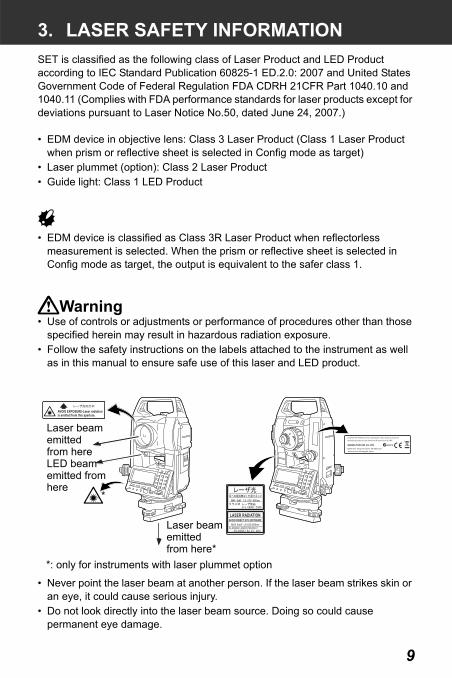
3. LASER SAFETY INFORMATIONSET is classified as the following class of Laser Product and LED Product according to IEC Standard Publication 60825-1 ED.2.0: 2007 and United States Government Code of Federal Regulation FDA CDRH 21CFR Part 1040.10 and 1040.11 (Complies with FDA performance standards for laser products except for deviations pursuant to Laser Notice No.50, dated June 24, 2007.)
• EDM device in objective lens: Class 3 Laser Product (Class 1 Laser Product when prism or reflective sheet is selected in Config mode as target)
• Laser plummet (option): Class 2 Laser Product• Guide light: Class 1 LED Product
• EDM device is classified as Class 3R Laser Product when reflectorless measurement is selected. When the prism or reflective sheet is selected in Config mode as target, the output is equivalent to the safer class 1.
Warning• Use of controls or adjustments or performance of procedures other than those
specified herein may result in hazardous radiation exposure.• Follow the safety instructions on the labels attached to the instrument as well
as in this manual to ensure safe use of this laser and LED product.
• Never point the laser beam at another person. If the laser beam strikes skin or an eye, it could cause serious injury.
• Do not look directly into the laser beam source. Doing so could cause permanent eye damage.
LASER RADIATIONAVOID DIRECT EYE EXPOSURE
MAX 5mW LD 625-695nmCLASS3R LASER PRUDUCT
IEC 60825-1 Ed. 2.0 : 2007
AVOID EXPOSURE-Laser radiationis emitted from this aperture.
Laser beam emittedfrom hereLED beamemitted fromhere
*
*: only for instruments with laser plummet option
Laser beamemitted from here*

3. LASER SAFETY INFORMATION
10
• Do not stare at the laser beam. Doing so could cause permanent eye damage.• If an eye injury is caused by exposure to the laser beam, seek immediate
medical attention from a licensed ophthalmologist.• Never look at the laser beam through a telescope, binoculars or other optical
instruments. Doing so could cause permanent eye damage. • Sight the targets so that laser beam does not stray from them.
Caution• Perform checks at start of work and periodic checks and adjustments with the
laser beam emitted under normal conditions. • When the instrument is not being used, turn off the power.• When disposing of the instrument, destroy the battery connector so that the
laser beam cannot be emitted.• Operate the instrument with due caution to avoid injuries that may be caused
by the laser beam unintentionally striking a person in the eye. Avoid setting the instrument at heights at which the path of the laser beam may strike pedestrians or drivers at head height.
• Never point the laser beam at mirrors, windows or surfaces that are highly reflective. The reflected laser beam could cause serious injury.
• When using the Laser-pointer function, be sure to turn OFF the output laser after distance measurement is completed. Even if distance measurement is canceled, the Laser-pointer function is still operating and the laser beam continues to be emitted. (After turning ON the Laser-pointer, the laser beam is emitted for 5 minutes, and then automatically switches OFF. But in the Status screen and when target symbol (ex. ) is not displayed in the Measurement mode, the laser beam is not automatically turned off. )
• Only those who have been received training as per the following items shall use this product.
• Read the Operator’s manual for usage procedures for this product.• Hazardous protection procedures (read this chapter).• Requisite protective gear (read this chapter).• Accident reporting procedures (stipulate procedures beforehand for
transporting the injured and contacting physicians in case there are laser induced injuries).
• Persons working within the range of the laser beam are advised to wear eye protection which corresponds to the laser wavelength of the instrument being used.
• Areas in which the lasers are used should be posted with laser warning notices.

11
4. SET FUNCTIONS
1 Handle2 Handle securing screw3 External interface hatch
SD card slotUSB port
4 Instrument height mark5 Battery cover6 Operation panel7 Data input/output connector
(SET350RX/550RX/650RX)8 Tribrach clamp9 Base plate10 Levelling foot screw11 Circular level adjusting screws12 Circular level13 Display14 Objective lens (Includes Laser-
pointer function)
15 Tubular compass slot16 Optical plummet focussing ring17 Optical plummet reticle cover18 Optical plummet eyepiece
(16-18: Not included on instruments with optional laser plummet)
19 Horizontal clamp20 Horizontal fine motion screw21 Beam detector for wireless
keyboard (Not included on SET650RX)
22 Plate level23 Plate level adjusting screw24 Vertical clamp25 Vertical fine motion screw26 Telescope eyepiece screw27 Telescope focussing ring28 Laser radiation warning indicator29 Peep sight30 Instrument center mark
4.1 Parts of the Instrument
1
2
3
6
4
5
7
89
1011
12
13
14
15
16
17
18
19
2021
2223
2425
2627
282930

4. SET FUNCTIONS
12
SET250RX and Low Temperature Models only31 Data input/output connector32 External power source connector
Peep sightUse peep sight to aim the SET in the direction of the measurement point. Turn the instrument until the triangle in the peep sight is aligned with the target.
Instrument height markThe height of the SET is as follows:
• 192.5mm (from tribrach mounting surface to this mark)• 236mm (from tribrach dish (WA200) to this mark)
"Instrument height" is input when setting instrument station data and is the height from the measuring point (where SET is mounted) to this mark.
Laser-pointer FunctionA target can be sighted with a red laser beam in dark locations without the use of the telescope.
SOKKIA original Independent Angle Calibration System (IACS) technologyThis revolutionary technology provides an even higher level of stability and reliability for angle measurement. With IACS technology, the SET independently calibrates angle to a high degree of accuracy, and eliminates the need for a reference standard instrument when performing calibration.
Independent angle calibration cannot be performed by the user. Consult your local dealer.
3132

13
4. SET FUNCTIONS
Operation panel
"5.1 Basic Key Operation"
Laser radiation warning indicator
Laser radiation warning indicator is red when laser beam is emitted or laser-pointer is used, and laser beam status can be known from the telescope eyepiece side.
?$ #%@/
Display
Softkeys
Beam detector for wireless keyboard
Laser radiation warning indicator

4. SET FUNCTIONS
14
Wireless keyboard
"36. OPTIONAL ACCESSORIES"
• Wireless keyboard cannot be used on SET650RX.
Key panel
Beam source
Strap attachmenthole
{A} to {Z}
Softkeyselecting keys
{FUNC} {MEAS}
{ }
{SFT}{BS}
{ESC}
{A/N}

15
4. SET FUNCTIONS
Guide light
Guide light and Guide light indicatorSetting-out measurement etc. can be carried out effectively using the Guide light. The Guide light is composed of a light that is divided into a red and a green light. A poleman can ascertain the present position by checking the Guide light color.
Guide light status
The Guide light indicator is lit when the Guide light is ON.
Light status Meaning
Red (From position of poleman) Move target left
Green (From position of poleman) Move target right
Red and Green Target is at correct horizontal position
Guide lightGuide light
indicator
green red

4. SET FUNCTIONS
16
4.2 Mode Diagram
Media selection
3
IntersectionsTraverse
Set-out line
Point projectionSet-out arc
Note
Stn. data
Dist Coord
Dist + Coord data
250RXS/N
Change Password
Backsight data
View
Dialup
Deletion
MEDIA
File status
[MEDIA]
Media
Save dataLoad known Pt.
Quick formatMedia mode
Instr. configInstr. const

17
4. SET FUNCTIONS
• Bluetooth communication is only possible with instruments incorporating the Bluetooth module.
• Use of this technology must be authorized according to telecommunications regulations of the country where the instrument is being used. Contact your local dealer in advance.
"39. REGULATIONS" • Sokkia Topcon Co., Ltd. is not liable for the content of any transmission nor any
content related thereto. When communicating important data, run tests beforehand to ascertain that communication is operating normally.
• Do not divulge the content of any transmission to any third party.
Radio interference when using Bluetooth technology
Bluetooth communication with the SET uses the 2.4 GHz frequency band. This is the same band used by the devices described below.
•Industrial, scientific, and medical (ISM) equipment such as microwaves and pacemakers.• portable premises radio equipment (license required) used in factory production lines etc.• portable specified low-power radio equipment (license-exempt) •IEEE802.11b/IEEE802.11g standard wireless LAN devices
The above devices use the same frequency band as Bluetooth communications. As a result, using the SET within proximity to the above devices may result in interference causing communication failure or reduction of transmission speed.
Although a radio station license is not required for this instrument, bear in mind the following points when using Bluetooth technology for communication.
Regarding portable premises radio equipment and portable specified low-power radio equipment:
• Before starting transmission, check that operation will not take place within the vicinity of portable premises radio equipment or specified low-power radio equipment.
• In the case that the instrument causes radio interference with portable premises radio equipment, terminate the connection immediately and take measures to prevent further interference (e.g. connect using an interface cable).
• In the case that the instrument causes radio interference with portable specified low-power radio equipment, contact your local dealer.
4.3 Bluetooth Wireless Technology

4. SET FUNCTIONS
18
When using the SET in proximity to IEEE802.11b or IEEE802.11g standard wireless LAN devices, turn off all devices not being used.
• Interference may result, causing transmission speed to slow or even disrupting the connection completely. Turn off all devices not being used.
Do not use the SET in proximity to microwaves.• Microwave ovens can cause significant interference resulting in
communication failure. Perform communication at a distance of 3m or more from microwave ovens.
Refrain from using the SET in proximity to televisions and radios.• Televisions and radios use a different frequency band to Bluetooth
communications.However, even if the SET is used within proximity to the above equipment with no adverse effects with regard to Bluetooth communication, moving a Bluetooth compatible device (including the SET) closer to said equipment may result in electronic noise in sound or images, adversely affecting the performance of televisions and radios.
Precautions regarding transmission
For best results• The usable range becomes shorter when obstacles block the line of sight, or
devices such as PDAs or computers are used. Wood, glass and plastic will not impede communication but the usable range becomes shorter. Moreover, wood, glass and plastic containing metal frames, plates, foil and other heat shielding elements as well as coatings containing metallic powders may adversely affect Bluetooth communication and concrete, reinforced concrete, and metal will render it impossible.
• Use a vinyl or plastic cover to protect the instrument from rain and moisture. Metallic materials should not be used.
• The direction of the Bluetooth antenna can have adverse effects upon usable range.
Reduced range due to atmospheric conditionsThe radio waves used by the SET may be absorbed or scattered by rain, fog, and moisture from the human body with the limit of usable range becoming lower as a result. Similarly, usable range may also shorten when performing communication in wooded areas. Moreover, as wireless devices lose signal strength when close to the ground, perform communication at as high a position as possible.

19
5. BASIC OPERATION
Learn basic key operations here before you read each measurement procedure.Location of operation keys on the panel and Location of operation keys on the wireless keyboard : "4.1 Parts of the Instrument"
• Wireless keyboard (SF14) (Optional accessory) makes key operation easier and speedier.
Specification of the keyboard: "36. OPTIONAL ACCESSORIES"
Power ON / OFF
Lighting up the display and key
Switching target typeTarget type can be switched only on the screen where the target symbol (ex. ) is displayed.
Target symbol displayed: "5.2 Display Functions", Switching the target type in Config mode": "30.1 EDM Settings"
Switching the Laser-pointer/Guide light ON/OFF
Selecting laser-pointer/guide light: "30.1 EDM Settings"
• After turning ON the laser-pointer/guide light, the laser beam is emitted for 5 minutes, and then automatically switches OFF. But in the Status screen and when target symbol (ex. ) is not displayed in the Meas mode, the laser beam is not automatically turned off.
5.1 Basic Key Operation
{ON} Power On{ON} (while pressing)+ { } Power Off
{ } Switch the screen/key backlight On / Off
{SFT} Switches between target types (Prism/Sheet/None(reflectorless))
{ } (Press and hold ) To turn the laser-pointer/guide light ON/OFF, press and hold until a beep sounds.

5. BASIC OPERATION
20
Softkey operationSoftkeys are displayed on the bottom line of the screen.
Inputting letters/figures
Example :Entering "JOB M" in the JOB name field1. Press {SFT} to enter the alphabet
input modeAlphabet input mode is indicated by an "A" on the right of the screen.
2. Press {4}."J" is displayed.
3. Press {5} three times."O" is displayed.
4. Press {7} twice."B" is displayed.
5. Press { } once.
Input a blank space.
{F1} to {F4} Select the function matching the softkeys{FUNC} Toggle between Meas mode screen pages
(when more than 4 softkeys are allocated)
{SFT} Switch between numeric and alphabetic characters.
{0} to {9} During numeric input, input number of the key.During alphabetic input, input the characters displayed above the key in the order they are listed.
{.}/{±} Input a decimal point/plus or minus sign during numeric input.During alphabetic input, input the characters displayed above the key in the order they are listed.
{ }/{ } Right and left cursor/Select other option.{ESC} Cancel the input data.{BS} Delete a character on the left.{ } Select/accept input word/value.

21
5. BASIC OPERATION
6. Press {5} once. "M" is displayed. Press { } to complete inputting.
Selecting options
Example: Select a reflector type1. Press [EDM] in page 2 of Meas mode.
2. Move to “Reflector” using { }/{ }.
3. Display the option you want to select using { }/{ }.Switches between “Prism”, “Sheet” and “None.”
4. Press { } or { } to move to the next option.The selection is set and you can set the next item.
Switching modes
"4.2 Mode Diagram"
Other operation
{ }/{ } Up and down cursor{ }/{ } Right and left cursor/Select other option{ } Accept the option
[CNFG] From Status mode to Config Mode (Configuration Mode)
[MEAS] From Status mode to Meas Mode (Measurement Mode)
[MEDIA] From Status mode to Media mode[MEM] From Status mode to Memory Mode{ESC} Return to the Status mode from each Mode
{ESC} Return to the previous screen
M
Illum.hold: Laser

5. BASIC OPERATION
22
Status screen
Meas Mode screen
Measuring screen
Input screen
* 1 DistanceSwitching distance display status: "30.2 Configuration -Config Mode-"S : Slope distanceH : Horizontal distanceV : Height difference
5.2 Display Functions
250RXS/NSET
MEDIA
6
/ Guide light-pointer
Laser is emited *9
F i n e
APrevious page
Next page
Input mode *10
OK

23
5. BASIC OPERATION
* 2 Vertical angleSwitching vertical angle display status: "30.2 Configuration -Config Mode-"ZA : Zenith angle (Z=0)VA : Vertical angle (H=0/H=±90)
To switch vertical angle/slope in %, press [ZA/%]
* 3 Horizontal anglePress [R/L] to switch the display status.HAR: Horizontal angle rightHAL: Horizontal angle left
* 1,2,3To switch usual “S, ZA, HAR” display to “S, H, V”, press [ SHV].
* 4 Remaining battery power (Temperature=25°C, EDM on)
"6.1 Battery Charging"
*5 Target displayPress {SFT} to switch the selected target. This key function can be used only on the screens on which the target symbol is displayed.
:prism:reflective sheet:reflectorless
* 6 Tilt angle compensationWhen this symbol is displayed, the vertical and horizontal angles are automatically compensated for small tilt errors using 2-axis tilt sensor.
Tilt compensation setting: "30.2 Configuration -Config Mode-"
*7 Laser-pointer/Guide light display Selecting Laser-pointer/Guide light: "30.1 EDM Settings", Switching Laser-pointer/Guide light ON/OFF : "5.1 Basic Key Operation"
Using BDC46B
Using external battery Battery level
level 3 Full power
level 2 Plenty of power remains.
level 1 Half or less power remains.level 0 Little power remains. Charge the battery.
(This symbol is displayed
every 3 seconds)
No power remains. Stop the measurement and charge thebattery.

5. BASIC OPERATION
24
:Laser-pointer is selected and ON:Guide light is selected and ON
*8 Bluetooth communication status: Connection established (“Mode” is set to “Slave”)
: Connection established (“Mode” is set to “Master”)
(flashing): Connecting (“Mode” is set to “Slave”)
(flashing): Connecting (“Mode” is set to “Master”)
(flashing): Waiting
(flashing): Disconnecting ("Mode is set to "Slave")
(flashing): Disconnecting (“Mode” is set to “Master”)
: Bluetooth device is OFF (“Mode” is set to “Slave”)
: Bluetooth device is OFF (“Mode” is set to “Master”)
*9 Appears when laser beam is emitted for distance measurement
*10 Input modeA :Inputting capital letters and figures.a :Inputting small letters and figures.

25
6. USING THE BATTERY
The battery has not been charged at the factory.
• Do not short circuit. Heat or ignition could result.• Batteries cannot be charged, even when the charging lamp is flashing, when
the temperature is outside the charging temperature range. Always charge batteries within the charging temperature range.
• Do not leave the battery in places exposed to high temperatures (more than 35°C). Doing so may reduce the life of the battery.
• Charge the battery once a month to maintain its quality when not in use for long periods.
• Do not charge the battery just after charging is completed. Battery performance may decline.
• Do not use to charge batteries other than those specified.• If you allow the battery level to get too low, the battery may not be rechargeable
or operating time may decline. Keep the battery always charged.• The charger will become rather hot during use. This is normal.
PROCEDURE
1. Connect the power cable to the CDC68 charger and plug the charger into the wall outlet.
2. Mount the battery (BDC46B) in the charger (CDC68) by matching the grooves on the battery with the guides on the charger.When charging starts, the lamp starts blinking.
3. Charging takes approximately 2.5 hours (25°C).The lamp lights when charging is finished.
4. Remove the battery and unplug the charger.
6.1 Battery Charging

6. USING THE BATTERY
26
• Slots 1 and 2: The charger starts charging the battery mounted first. If you place two batteries in the charger, the battery in slot 1 is charged first, and then the battery in slot 2. (step 2)
• Charging lamp: The charging lamp is off when the charger is outside the charging temperature range or when the battery is mounted incorrectly. If the lamp is still off after the charger falls within its charging temperature range and the battery is mounted again, contact your local dealer. (steps 2 and 3)
• Charging time: Charging can take more than 2.5 hours when temperatures are either especially high or low.
Mount the charged battery.
• When removing the battery, turn the power off.• When installing/removing the battery, make sure that moisture or dust particles
do not come in contact with the inside of the instrument.
PROCEDURE
1.
6.2 Installing/Removing the Battery
Batteryrelease button
Open the battery cover:Press the battery releasebutton downward

27
6. USING THE BATTERY
2.
3.
• Battery coverIf the battery cover is open during power on, SET notifies you by displaying the screen below and beeping.When the battery cover is closed, the previous screen is restored.
Battery
Terminal
Insert and pressdown on the topof the battery untila click is heard.
Close the battery cover:Insert the lip on the top of the batteryrelease button into the groove on the SETand press until a click is heard.

28
7. SETTING UP THE INSTRUMENT
• Mount the battery in the instrument before performing this operation because the instrument will tilt slightly if the battery is mounted after levelling.
PROCEDURE Centering with the optical plummet eyepiece
1. Make sure the legs are spaced at equal intervals and the head is approximately level.Set the tripod so that the head is positioned over the survey point.Make sure the tripod shoes are firmly fixed in the ground.
2. Place the instrument on the tripod head.Supporting it with one hand, tighten the centering screw on the bottom of the unit to make sure it is secured to the tripod.
3. Looking through the optical plummet eyepiece, turn the optical plummet eyepiece to focus on the reticle.Turn the optical plummet focusing ring to focus on the survey point.
7.1 Centering
Centering screw
Focussing on the survey point
Focussingon the reticle

29
7. SETTING UP THE INSTRUMENT
PROCEDURE Centering with the laser plummet (option)
1. Set up the tripod and affix the instrument on the tripod head.
“PROCEDURE Centering with the optical plummet eyepiece” steps 1 and 2
2. Press {ON} to power on“POWER ON/OFF”
3. Press [TILT] in the second page of Meas Mode to display the circular level on the screen.
4. Press [L-ON].The laser plummet beam will be emitted from the bottom of the instrument.
5. Use { }/{ } to adjust the brightness of the laser.
6. Adjust the position of the instrument on the tripod until the laser beam is aligned with the center of the survey point.
7. Press [L-OFF] to turn the laser plummet off.Alternatively, press {ESC} to return to the previous screen. The laser plummet will switch off automatically.
L-ON
L-OFFL- lev.

7. SETTING UP THE INSTRUMENT
30
Instrument can be levelled using the screen.“ Levelling on the screen”
PROCEDURE
1. Adjust the levelling foot screws to center the survey point in the optical plummet reticle.
2. Center the bubble in the circular level by either shortening the tripod leg closest to the offcenter direction of the bubble or by lengthening the tripod leg farthest from the offcenter direction of the bubble. Adjust one more tripod leg to center the bubble.
Turn the levelling foot screws while checking the circular level until the bubble is centered in the center circle.
3. Loosen the horizontal clamp to turn the upper part of the instrument until the plate level is parallel to a line between levelling foot screws A and B.Center the air bubble using levelling foot screws A and B simultaneously.The bubble moves towards a clockwise rotated levelling foot screw.
7.2 Levelling
Tripod legsadjustment
31
7. SETTING UP THE INSTRUMENT
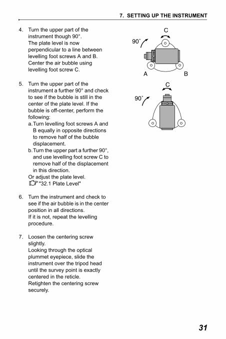
4. Turn the upper part of the instrument though 90°.The plate level is now perpendicular to a line between levelling foot screws A and B.Center the air bubble using levelling foot screw C.
5. Turn the upper part of the instrument a further 90° and check to see if the bubble is still in the center of the plate level. If the bubble is off-center, perform the following:a.Turn levelling foot screws A and
B equally in opposite directions to remove half of the bubble displacement.
b.Turn the upper part a further 90°, and use levelling foot screw C to remove half of the displacement in this direction.
Or adjust the plate level."32.1 Plate Level"
6. Turn the instrument and check to see if the air bubble is in the center position in all directions.If it is not, repeat the levelling procedure.
7. Loosen the centering screw slightly.Looking through the optical plummet eyepiece, slide the instrument over the tripod head until the survey point is exactly centered in the reticle.Retighten the centering screw securely.

7. SETTING UP THE INSTRUMENT
32
• When the instrument was centered using the laser plummet, emit the plummet beam again to check position over the survey point.
“PROCEDURE Centering with the laser plummet (option)”
8. Check again to make sure the bubble in the plate level is centeredIf not, repeat the procedure starting from step 3.
PROCEDURE Levelling on the screen
1. Press {ON} to power on"9. POWER ON/OFF"
2. Press [TILT] in the second page of Meas Mode to display the circular level on the screen.“ ” indicates bubble in circular level. The range of the inside circle is ±4' and the range of the outside circle is ±6'.Tilt angle values X and Y are also displayed on the screen.
3. Center “ ” in the circular level"7.2 Levelling" steps 1 to 2
4. Turn the instrument until the telescope is parallel to a line between levelling foot screws A and B, then tighten the horizontal clamp.
L-ON

33
7. SETTING UP THE INSTRUMENT
5. Set the tilt angle to 0° using foot screws A and B for the X direction and levelling screw C for the Y direction.
6. When levelling is completed, press {ESC}.

34
8. FOCUSSING AND TARGET SIGHTING
• When sighting the target, strong light shining directly into the objective lens may cause the instrument to malfunction. Protect the objective lens from direct light by attaching the lens hood.Observe to the same point of the reticle when the telescope face is changed.
PROCEDURE
1. Look through the telescope eyepiece at a bright and featureless background.Turn the eyepiece screw clockwise, then counterclockwise little by little until just before the reticle image becomes focussed.Using these procedures, frequent reticle refocussing is not necessary since your eye is focussed at infinity.
2. Loosen the vertical and horizontal clamps, then use the peep sight to bring the target into the field of view. Tighten both clamps.
3. Turn the telescope focussing ring to focus on the target.Turn the vertical and horizontal fine motion screws to align the target with the reticle.The last adjustment of each fine motion screw should be in the clockwise direction.
35
8. FOCUSSING AND TARGET SIGHTING
4. Readjust the focus with the focussing ring until there is no parallax between the target image and the reticle.
Eliminating parallaxThis is the relative displacement of the target image with respect to the reticle when the observer’s head is moved slightly before the eyepiece.Parallax will introduce reading errors and must be removed before observations are taken. Parallax can be removed by refocussing the reticle.

36
9. POWER ON/OFFSetting “V manual”: "30.2 Configuration -Config Mode-", Setting/changing password: "30.4 Changing Password"
PROCEDURE Power ON
1. Press {ON}.When the power is switched on, a self-check is run to make sure the instrument is operating normally.
• When password is set, the display appears as at right. Input password and press { }.
• When “V manual” is set to “Yes”, the display appears as at right.
Manually indexing the vertical circle by face left, face right measurements: "38. EXPLANATION"
• If the Tilt screen is displayed, the instrument tilt sensor is indicating that the instrument is out of level. Level the instrument once again and the horizontal and vertical angles will be displayed.
"7. SETTING UP THE INSTRUMENT PROCEDURE Levelling on the screen"
Press {ESC} to skip levelling.
After that, Meas Mode screen appears.
If “Out of range” or the Tilt screen is displayed, level the instrument again.
P a s s w o r d :
A
0 Set
L-ON

37
9. POWER ON/OFF
• When “Resume” in “Instr. config” is set to “On”, the screen previous to power off is displayed (except when missing line measurement was being performed).
"30.2 Configuration -Config Mode-"• “Tilt crn” in “Obs. condition” should be set to “No” if the display is unsteady due
to vibration or strong wind."30.2 Configuration -Config Mode-"
PROCEDURE Power OFF
Press { } while pressing { }.
• When there is almost no battery power remaining, the symbol will be displayed every 3 seconds. In this event, stop measurement, switch off the power and charge the battery or replace with a fully charged battery.
• To save power, power to the SET is automatically cut off if it is not operated for a fixed period of time. This time period can be set in "Power off" in <Instr.config.>.
"30.2 Configuration -Config Mode-"

38
10.CONNECTING TO EXTERNAL DEVICES
Bluetooth wireless technology allows the SET to communicate wirelessly with other Bluetooth devices. Bluetooth wireless communication settings are performed in “Comms setup” in Config Mode.
PROCEDURE Basic Settings
1. Select ”Comms setup” in Config mode
2. Set ”Wireless” to “Yes”.
3. Select ”Bluetooth setup”.
4. Set "Mode" to either "Master" or "Slave".
" Bluetooth connections"
5. Set “Link”.Select a companion device from among the Bluetooth devices registered in the SET using { }/{ }.
Registering devices: “PROCEDURE Registering Bluetooth companion devices”
• "Link" setting is not necessary when "Mode" is set to "Slave".
6. Set "Authentication". Select "Yes" or "No".
10.1 Necessary settings for Bluetooth communication
Wireless :: YesBluetooth setupLink device listMy device info
Wireless : YesBluetooth setupLink device listMy device info
Mode
:
AuthenticationPasskey
: No
****
: Slave
Check sum : No
Mode : Master
:
AuthenticationPasskey
: No
****
Link : DEVICE1
Check sum : No

39
10. CONNECTING TO EXTERNAL DEVICES
7. Set "Passkey". Set the same passkey as that for your Bluetooth device.
• Up to 16 numeral characters can
be input. "0123" is the factory setting. Input characters will be displayed as asterisks (e.g. "*****").
8. Set check sum setting.
• Even when "Authentication" is set to "No", a passkey is requested when authentication is set on the Bluetooth device being used.
• When "Wireless" is set to "Yes", communication settings will not be displayed. It is recommended that the check sum setting is set to correspond with those of the Bluetooth device.
Bluetooth connections• Communication between a pair of Bluetooth devices requires one device
to be set as the "Master" and the other as the "Slave". To initiate connections from the SET side, set the SET as the "Master" device. To initiate connections from the paired device side, set the SET as the "Slave" device.
PROCEDURE Registering Bluetooth companion devices
1. Select "Comms setup" in Config mode.
2. Set "Wireless" to "Yes".
3. Select "Link device list". Wireless : YesBluetooth setup
My device infoLink device list

10. CONNECTING TO EXTERNAL DEVICES
40
4. Register your Bluetooth device(s).Select a device and press [EDIT] to update related information.
• Select a device and press { } to show details.Press [PREV]/[NEXT] to display details of the previous/next device.
• Press [DEL] to delete information for the selected device.
5. Input "Name" (device name) and "BD ADDR" (address) and press [REG].
• 12 hexadecimal digits can be input.
• By pressing [INQ], it is also possible to inquire about devices in the immediate vicinity and register their address.Select an address from the list of devices discovered and press [OK]. The address is displayed "BD ADDR". (If SET cannot find any devices within 30 sec., the inquiry will be canceled.)
PROCEDURE Displaying Bluetooth information for the SET
1. Select "Comms setup" in Config mode.
2. Set "Wireless" to "Yes".
DEVICE1Link device list
DEVICE2DEVICE3DEVICE4
DELEDIT
Device (Details) Name: DEVICE2BD_ADDR: 0123456789AB
PREV NEXT
YES
DEVICE1deletion Confirm?
No NO
Device registration Name: DEVICE1BD_ADDR: 0123456789AB
REGINQ
Inquiry... 0123456789AB123456789ABC23456789ABCD3456789ABCDE
OKSTOP
41
10. CONNECTING TO EXTERNAL DEVICES
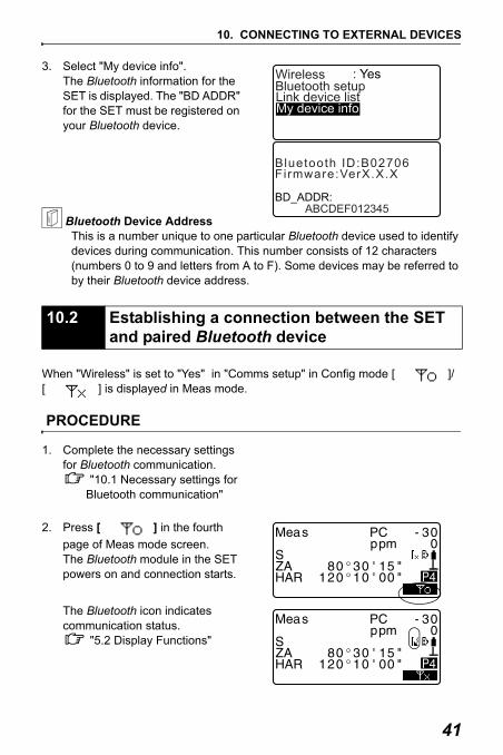
3. Select "My device info". The Bluetooth information for the SET is displayed. The "BD ADDR" for the SET must be registered on your Bluetooth device.
Bluetooth Device AddressThis is a number unique to one particular Bluetooth device used to identify devices during communication. This number consists of 12 characters (numbers 0 to 9 and letters from A to F). Some devices may be referred to by their Bluetooth device address.
When "Wireless" is set to "Yes" in "Comms setup" in Config mode [ ]/[ ] is displayed in Meas mode.
PROCEDURE
1. Complete the necessary settings for Bluetooth communication.
"10.1 Necessary settings for Bluetooth communication"
2. Press [ ] in the fourth page of Meas mode screen.The Bluetooth module in the SET powers on and connection starts.
The Bluetooth icon indicates communication status.
"5.2 Display Functions"
10.2 Establishing a connection between the SET and paired Bluetooth device
Wireless : YesBluetooth setupLink device listMy device info
Firmware:VerX.X.X
BD_ADDR: ABCDEF012345
Bluetooth ID:B02706
4
4

10. CONNECTING TO EXTERNAL DEVICES
42
• When "Mode" in "Bluetooth setup" is set to "Slave", the establishing of a connection can only be initiated from the "Master" Bluetooth device.
• When "Mode" in "Bluetooth setup" is set to "Master", SET will attempt to establish a connection with the designated Bluetooth device (specified in "Link" in "Bluetooth setup").
• Softkeys (in Meas mode and <Aiming>)[ ]:Press to enter waiting status ("Mode" is set to "Slave")/establish
a connection ("Mode" is set to "Master")[ ]:Press to cancel the connection/exit waiting status ("Mode" is set
to "Slave")/stop establishing or cancel a connection ("Mode" is set to "Master")
• Audio tones(While connecting/disconnecting)
Start paging/waiting: short beepConnection successfully established: long beepConnection canceled/being canceled: two short beeps Paging failed/waiting time out: two short beeps
(While inquiring about other Bluetooth devices)New device discovered: short beepInquiry complete: long beep
Data collectors can also be set as companion devices for wireless communication and can be used to initiate measurement.
PROCEDURE Performing measurement using a data collector
1. Complete the necessary settings for Bluetooth communication.
"10.1 Necessary settings for Bluetooth communication"
10.3 Measurement using Bluetooth communication

43
10. CONNECTING TO EXTERNAL DEVICES
2. Verify the current connection status by checking the Bluetooth icon in the Meas mode screen.
"10.2 Establishing a connection between the SET and paired Bluetooth device"
3. Initiate measurement using your Bluetooth device (e.g. a data collector). SET will respond and measurement will start. Measured values are then displayed in the Meas mode screen.

10. CONNECTING TO EXTERNAL DEVICES
44
It is possible to set a computer as the companion device and register known point data or output JOB data via wireless communication.
PROCEDURE Entering known point coordinate data from an external instrument
1. Complete the necessary settings for Bluetooth communication.
"10.1 Necessary settings for Bluetooth communication"
2. Verify the current connection status by checking the Bluetooth icon in the Meas mode screen.
"10.2 Establishing a connection between the SET and paired Bluetooth device"
3. Register known point data in Memory mode.
"26.1 Registering/Deleting Known Point Data PROCEDURE Entering known point coordinate data from an external instrument"
Coordinate data starts being entered from the external instrument.
• If a connection has not yet been established, the screen at right is displayed. (Screens differ depending on the "Mode" setting. The displayed screen appears when "Mode" is set to "Slave".) After a connection has been established, the data is entered.
10.4 Registering/Outputting data using Bluetooth communication
Comms inputWaiting for connection...

45
10. CONNECTING TO EXTERNAL DEVICES
PROCEDURE Outputting JOB data to a host computer
1. Complete the necessary settings for Bluetooth communication.
"10.1 Necessary settings for Bluetooth communication"
2. Verify the current connection status by checking the Bluetooth icon in the Meas mode screen.
"10.2 Establishing a connection between the SET and paired Bluetooth device"
3. Output JOB data in Memory mode.
"27.1 Outputting JOB Data to Host Computer"
SET starts outputting data.
• If a connection has not yet been established, the screen at right is displayed. (Screens differ depending on the "Mode" setting. The displayed screen appears when "Mode" is set to "Slave".) After a connection has been established, the data is output.
Comms output
Format SDR33 Sending 12
Comms outputWaiting for connection...

10. CONNECTING TO EXTERNAL DEVICES
46
PROCEDURE Basic cable settings
1. Connect the SET to the external device using the cable.
Cables: 36. OPTIONAL ACCESSORIES
2. Select “Comms setup” in Config mode. Set communication conditions.
"30.2 Configuration -Config
Mode-"
10.5 Connecting via Communication Cable

47
11. ANGLE MEASUREMENTThis section explains the procedures for basic angle measurement.
Use the “0SET” function to measure the included angle between two points. The horizontal angle can be set to 0 at any direction.
PROCEDURE
1. Sight the first target as at right.
2. In the first page of the Meas mode screen, press [0SET].[0SET] will flash, so press [0SET] again.The horizontal angle at the first target becomes 0°.
3. Sight the second target.
The displayed horizontal angle (HAR) is the included angle between two points.
11.1 Measuring the Horizontal Angle between Two Points (Horizontal Angle 0°)

11. ANGLE MEASUREMENT
48
You can reset the horizontal angle to a required value and use this value to find the horizontal angle of a new target.
PROCEDURE
1. Sight the first target.
2. In the second page of the Meas mode screen, press [H.ANG].Select “Angle”.
3. Enter the angle you wish to set, then press [OK].The value that is input as the horizontal angle is displayed.
• When [REC] is pressed, backsight angle can be set and recorded in the current JOB.
"24.2 Recording Backsight Point"
4. Sight the second target.The horizontal angle from the second target to the value set as the horizontal angle is displayed.
• Pressing [HOLD] performs the same function as above.• Press [HOLD] to set the displayed horizontal angle. Then, set the angle that is
in hold status to the direction you require.Allocating [HOLD]: "30.3 Allocating Key Functions"
11.2 Setting the Horizontal Angle to a Required Value (Horizontal Angle Hold)
:
Set H angleTake BS
89 59 50347 23 46
REC OK125.3220

49
11. ANGLE MEASUREMENT
To find the horizontal angle with greater precision, perform repetition measurement.
• The maximum number of angle measurements that can be made is 10.
PROCEDURE
1. In the second page of Meas mode screen, press [MENU], then select "Repetition".
2. Sighting the first target, press [OK].
3. Sighting the second target, press [OK].
4. Sighting the first target a second time, press [OK].
5. Sighting the second target a second time, press [OK].The added value of the horizontal angle is displayed on the second line “HARp” and the average value of the horizontal angle is displayed on the fourth line “Ave.”.
11.3 Horizontal Angle Repetition
MenuCoordinateS-OOffsetRepetitionMLM

11. ANGLE MEASUREMENT
50
• Return to the previous measurement of the first target and redo it: [CE].(Effective when the display shows “Take BS”)
6. When continuing the repetition measurement, repeat steps 4 to 5.
7. When the repetition measurement is completed, press {ESC}.
• It is also possible to perform repetition measurement by pressing [REP] when allocated to the Meas mode screen.
Allocating [REP]: "30.3 Allocating Key Functions"
The following explains angle measurement and the features used to output measurement data to a computer or peripheral equipment.
Bluetooth communication: "10. CONNECTING TO EXTERNAL DEVICES"Communication cables: "36. OPTIONAL ACCESSORIES"Output format and command operations: “Interfacing with the SOKKIA SDR Electronic Field Book” and “Command Explanations” manuals.
PROCEDURE
1. Connect SET and host computer.
2. Allocate the [D-OUT] softkey to the Meas mode screen.
"30.3 Allocating Key Functions"
3. Sight the target point.
4. Press [D-OUT] and select “Angle Data”.Output measurement data to peripheral equipment.
11.4 Angle Measurement and Outputting the Data

51
12.DISTANCE MEASUREMENTPerform the following settings as preparation for distance measurement.• Distance measurement mode• Target type• Prism constant correction value• Atmospheric correction factor• EDM ALC
"30.1 EDM Settings"/"30.2 Configuration -Config Mode-"
CAUTION• When using the Laser-pointer function, be sure to turn OFF the output laser
after distance measurement is completed. Even if distance measurement is canceled, the Laser-pointer function is still operating and the laser beam continues to be emitted. (After turning ON the Laser-pointer, the laser beam is emitted for 5 minutes, and then automatically switches OFF. But in the Status screen and when target symbol (ex. ) is not displayed in the Meas mode, the laser beam is not automatically turned off.)
• Make sure that the target setting on the instrument matches the type of target used. SET automatically adjusts the intensity of the laser beam and switches the distance measurement display range to match the type of target used. If the target does not correspond to the target settings, accurate measurement results cannot be obtained.
• Accurate measurement results cannot be obtained if the objective lens is dirty. Dust it off with the lens brush first, to remove minute particles. Then, after providing a little condensation by breathing on the lens, wipe it off with the wiping cloth.
• During reflectorless measurement, if an object with a high reflective factor (metal or white surface) is positioned between the SET and the target, accurate measurement results may not be received.
• Scintillation may affect the accuracy of distance measurement results.Should this occur, repeat measurement several times and use the averaged value of the obtained results.

12. DISTANCE MEASUREMENT
52
• Check to make sure that sufficient reflected light is returned by the reflective prism sighted by the telescope. Checking the returned signal is particularly useful when performing long distance measurements.
• When the light intensity is sufficient even though the center of the reflective prism and the reticle are slightly misaligned (short distance etc.), “*” will be displayed in some cases, but in fact, accurate measurement is impossible. Therefore make sure that the target center is sighted correctly.
PROCEDURE
1. Allocate the [AIM] softkey to the Meas mode screen.
"30.3 Allocating Key Functions"
2. Accurately sight the target.
3. Press [AIM].<Aiming> is displayed.The intensity of the light of the returned signal is displayed by a gauge.
• The more displayed, the greater the quantity of reflected light.
• If “*” is displayed, only enough light for the measurement is returned.
• When “*” is not displayed, accurately resight the target. Press [BEEP] to make a buzzer sound when measurement is possible. Press [OFF] to shut off the buzzer.
• Press [DIST] to start distance measurement.
12.1 Returned Signal Checking

53
12. DISTANCE MEASUREMENT
4. Press {ESC} to finish signal checking and return to Meas Mode.
• When is displayed persistently, contact your local dealer.• If no key operations are performed for two minutes, the display automatically
returns to the Meas mode screen.
An angle can be measured at the same time as the distance.
PROCEDURE
1. Sight the target.
2. In the first page of Meas Mode, press [DIST] to start distance measurement.
When measurement starts, EDM information (distance mode, prism constant correction value, atmospheric correction factor) is represented by a flashing light.
A short beep sounds, and the measured distance data (S), vertical angle (ZA), and horizontal angle (HAR) are displayed.
12.2 Distance and Angle Measurement
F i n e

12. DISTANCE MEASUREMENT
54
3. Press [STOP] to quit distance measurement.
• Each time [ SHV] is pressed, S (Slope distance), H (Horizontal distance) and V (Height difference) are displayed alternately.
• If the single measurement mode is selected, measurement automatically stops after a single measurement.
• During fine average measurement, the distance data is displayed as S-1, S-2, ... to S-9. When the designated number of measurements has been completed, the average value of the distance is displayed in the [S-A] line.
• The distance and angle that are most recently measured remain stored in the memory until the power is off and can be displayed at any time.
"12.3 Recalling the Measured Data"
The distance and angle that are most recently measured remain stored in the memory until the power is off and can be displayed at any time.
The distance measurement value, vertical angle, horizontal angle, and the coordinates can be displayed. Distance measurement values converted into the horizontal distance, elevation difference, and the slope distance can also be displayed.
PROCEDURE
1. Allocate the [RCL] softkey to the Meas mode screen.
"30.3 Allocating Key Functions"
12.3 Recalling the Measured Data

55
12. DISTANCE MEASUREMENT
2. Press [RCL].The stored data that is most recently measured is displayed.
• If you have pressed [ SHV] beforehand, the distance values are converted into the horizontal distance, elevation difference, and the slope distance and recalled.
3. Press {ESC} to return to Meas mode.
The following explains distance measurement and the features used to output measurement data to a computer or peripheral equipment.
Communication cables: "36. OPTIONAL ACCESSORIES" Output format and command operations: “Interfacing with the SOKKIA SDR Electronic Field Book” and “Command Explanations” manuals.
PROCEDURE
1. Connect SET and host computer.
2. Allocate the [D-OUT] softkey to the Meas mode screen.
"30.3 Allocating Key Functions"
3. Sight the target point.
4. Press [D-OUT], and select “Dist data” to measure the distance and output the data to peripheral equipment.
5. Press [STOP] to stop outputting data and return to Meas Mode.
12.4 Distance Measurement and Outputting the Data

12. DISTANCE MEASUREMENT
56
An REM measurement is a function used to measure the height to a point where a target cannot be directly installed such as power lines, overhead cables and bridges, etc.The height of the target is calculated using the following formula.
Ht = h1 + h2h2 = S sin θ z1 x cot θ z2 - S cos θ z1
PROCEDURE
1. Set the target directly under or directly over the object and measure the target height with a tape measure etc.
2. After inputting the target height, accurately sight the target.
“ ”Press [DIST] in page 1 of Meas Mode to carry out measurement.
12.5 REM Measurement
ZenithZenith

57
12. DISTANCE MEASUREMENT
The measured distance data (S), vertical angle (ZA), and horizontal angle (HAR) are displayed. Press [STOP] to stop the measurement.
3. In the second page of Meas mode screen, press [MENU], then select "REM".
4. Press [OBS]. The REM measurement is started and the height from the ground to the object is displayed in “Ht.”.
5. Press [STOP] to terminate the measurement operation.
• To re-observe the target, sight the target, then press [OBS].
• When [REC] is pressed, REM data is saved.
"24. RECORDING DATA - RECORD MENU -"
REMResectionArea calculationSet-out line
Point projectionSet-out arc
Need Pr ism obs
REC

12. DISTANCE MEASUREMENT
58
6. Press {ESC} to finish measurement and return to the Meas mode screen.
• It is also possible to perform REM measurement by pressing [REM] when allocated to the Meas mode screen.
"30.3 Allocating Key Functions"• Inputting instrument and target height: Press [HT] to set instrument and target
height. It can be set also in “Stn. Orientation” of coordinate measurement."13.1 Entering Instrument Station Data and Azimuth Angle"

59
13.COORDINATE MEASUREMENTBy performing coordinate measurements it is possible to find the 3-dimensional coordinates of the target based on station point coordinates, instrument height, target height, and azimuth angles of the backsight station which are entered in advance.
• EDM setting can be done in coordinate measurement menu.Setting items: "30.1 EDM Settings"
Before coordinate measurement, enter instrument station coordinates, the instrument height, target height, and azimuth angle.
PROCEDURE
1. First measure the target height and instrument height with a tape measure, etc.
2. Press [COORD] in the first page of the Meas mode screen to display <Coord.>.
13.1 Entering Instrument Station Data and Azimuth Angle
13. COORDINATE MEASUREMENT
60
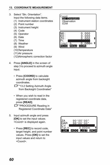
3. Select “Stn. Orientation”.Input the following data items.(1) Instrument station coordinates(2) Point number(3) Instrument height(4) Code(5) Operator(6) Date(7) Time(8) Weather(9) Wind(10)Temperature(11)Air pressure(12)Atmospheric correction factor
4. Press [ANGLE] in the screen of step 3 to proceed to azimuth angle input.
• Press [COORD] to calculate azimuth angle from backsight coordinates.
"13.2 Setting Azimuth Angle from Backsight Coordinates"
• When you wish to read in the registered coordinate data, press [READ].
"PROCEDURE Reading in Registered Coordinate Data"
5. Input azimuth angle and press [OK] to set the input values. <Coord> is displayed again.
• Press [REC] to record code, target height, and point number values. Press [OK] to set the input values and return to <Coord>.
Coord.Stn. OrientationObservationEDM
READ ANGLE COORD
Pt.
00 00000090
CdTgt.h 0.000mOK ADD LIST SRCH

61
13. COORDINATE MEASUREMENT
• Maximum point number size: 14 (alphanumeric)• Input range of instrument height: -9999.999 to 9999.999 (m)• Maximum code/operator size: 16 (alphanumeric)• Weather selection: Fine, Cloudy, Light rain, Rain, Snow• Wind selection: Calm, Gentle, Light, Strong, Very strong• Temperature range: -30 to 60 (°C) (in 1°C step)/-22 to 140 (°F) (in 1°F step)• Air pressure range: 500 to 1400 (hPa) (in 1 hPa step)/375 to 1050 (mmHg)
(in 1mmHg step)/14.8 to 41.3 (inch Hg) (in 0.1 inch Hg step)• Atmospheric correction factor range (ppm): -499 to 499
PROCEDURE Reading in Registered Coordinate Data
Known point data, coordinate data and instrument station data in the current JOB and Coordinate Search JOB can be read in.Confirm that the correct JOB containing the coordinates you want to read in is already selected in Coordinate Search JOB in Memory Mode.
"26.1 Registering/Deleting Known Point Data", "25.1 Selecting a JOB"1. Press [READ] when setting
Instrument Station.The list of registered coordinates is displayed.Pt. : Known point date
saved in the current JOB or in the Coordinate Search JOB.
Crd./ Stn : Coordinate data saved in the current JOB or in the Coordinate Search JOB.
2. Align the cursor with the required point number and press { }.The point number that was read and its coordinates in are displayed.
��0�.�0�0�0
COORDANGLE
Pt. PNT-001

13. COORDINATE MEASUREMENT
62
• [ ...P] = Use { }/{ } to move from page to page.
• [ ...P] = Use { }/{ } to select individual point.
• Press [TOP] to move to the first point number on the first page.
• Press [LAST] to move to the last point number on the last page.
• Press [SRCH] to move to the “Coordinate Data Search Screen.” Input the point number you want to search in “Pt. no.”The search may take time if many data are registered.
3. Press [OK].<Instrument Station Data Setting> is restored.
• You can edit the coordinate data that was read in. Editing does not affect the original coordinate data. After editing, the point number is no longer displayed.
• The point number that was read in is displayed until the current JOB is changed.• When [SRCH] is pressed, SET searches data in the current JOB first, then in
the Coordinate Search JOB.• If more than two points with the same point name exist in the current JOB, SET
finds the newer data only.

63
13. COORDINATE MEASUREMENT
Set the azimuth angle of the backsight station by calculating by the coordinates.
PROCEDURE
1. Enter the instrument station data."13.1 Entering Instrument Station Data and Azimuth Angle " steps 1 to 3
2. Press [COORD] to proceed to backsight coordinate input.
3. Input the backsight station coordinates and press [OK]. Angle measurement values are displayed in real time. Calculated Azimuth angle is also displayed.
13.2 Setting Azimuth Angle from Backsight Coordinates
READ ANGLE COORD
Pt.
NBS : 1.000Backsight
READ OK
ZBS : EBS : 1.000
<Null>

13. COORDINATE MEASUREMENT
64
• Press [DIST] to perform a horizontal distance check.
• Press [HT] to set instrument and target height.
• Press [REC] to store check data in the current JOB
• When you wish to read in the registered coordinate data, press [READ].
"13.1 Entering Instrument Station Data and Azimuth Angle PROCEDURE Reading in Registered Coordinate Data"
4. Press [YES] in the screen of step 3 to set azimuth angle. <Coord> is displayed again.
• When storing the azimuth angle in the current JOB, press [REC].
24.2 Recording Backsight Point, PROCEDURE Inputting azimuth angle"
calc H
BS Hdist check
REC OKdH obs H 0.000m
0.000m
0.000m
H T
1 2 3 1 2 ’ 3 4 " 9 0 1 2 ’ 3 4 "
Take BSBacksight
REC YESAzmth 4 5 0 0 ’ 0 0 "
NODIST
00 00000090
CdTgt.h 0.000mOK ADD LIST SRCH
S 100.000m
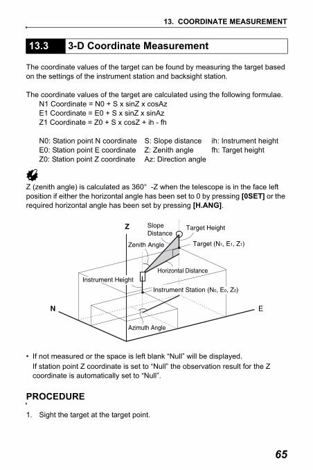
65
13. COORDINATE MEASUREMENT
The coordinate values of the target can be found by measuring the target based on the settings of the instrument station and backsight station.
The coordinate values of the target are calculated using the following formulae. N1 Coordinate = N0 + S x sinZ x cosAzE1 Coordinate = E0 + S x sinZ x sinAzZ1 Coordinate = Z0 + S x cosZ + ih - fh
N0: Station point N coordinate S: Slope distance ih: Instrument heightE0: Station point E coordinate Z: Zenith angle fh: Target heightZ0: Station point Z coordinate Az: Direction angle
Z (zenith angle) is calculated as 360° -Z when the telescope is in the face left position if either the horizontal angle has been set to 0 by pressing [0SET] or the required horizontal angle has been set by pressing [H.ANG].
• If not measured or the space is left blank “Null” will be displayed. If station point Z coordinate is set to “Null” the observation result for the Z coordinate is automatically set to “Null”.
PROCEDURE
1. Sight the target at the target point.
13.3 3-D Coordinate Measurement

13. COORDINATE MEASUREMENT
66
2. In <Coord>, select “Observation” to start measurement. The coordinate value of the target is displayed. Press [STOP] to quit measurement.
• The tilt screen is displayed if the instrument is out of level.Level the instrument.
"7. SETTING UP THE INSTRUMENT PROCEDURE Levelling on the screen"
• By pressing [HT], the instrument station data can be reset. When the target height of the next target is different, reenter the target height before beginning the observation.
• [REC]: records measurement results
• [AUTO]: starts measurement and automatically records results after [STOP] has been pressed.
Recording method: "24. RECORDING DATA - RECORD MENU -"
3. Sight the next target and press [OBS] or [AUTO] to begin measurement. Continue until all targets have been measured.
• When coordinate measurement is completed, press {ESC} to return to <Coord>.
Coord.Stn. OrientationObservationEDM
AUTO

67
13. COORDINATE MEASUREMENT
The following explains coordinate measurement and the features used to output measurement data to a computer or peripheral equipment.
Communication cables: "36. OPTIONAL ACCESSORIES" Output format and command operations: "Interfacing with the SOKKIA SDR
Electronic Field Book" and "Command Explanations" manuals
PROCEDURE
1. Connect SET and host computer.
2. Allocate the [D-OUT] softkey to the Meas mode screen.
"30.3 Allocating Key Functions"
3. Sight the target point.
4. Press [D-OUT], and select “Coord data” to output measurement data.
5. Press [STOP] to stop outputting data and return to Meas Mode
13.4 Coordinate Measurement and Outputting the Data
Coord data
Data outDist dataAngle data

68
14.RESECTION MEASUREMENTResection is used to determine the coordinates of an instrument station by performing multiple measurements of points whose coordinate values are known. Registered coordinate data can be recalled and set as known point data. Residual of each point can be checked, if necessary.
• All the N, E, Z or only Z data of an instrument station is calculated by measuring the known points.
• Coordinate resection measurement overwrites the N, E and Z data of the instrument station, but height resection does not overwrite N and E. Always perform resection measurement in the sequence described in "14.1 Coordinate Resection Measurement" and "14.2 Height Resection Measurement".
• Input known coordinate data and calculated instrument station data can be recorded in the current JOB.
"25. SELECTING/DELETING A JOB"
Entry OutputCoordinates of known point : (Xi, Yi, Zi) Station point coordinates : (X0,Y0, Z0)Observed horizontal angle : HiObserved vertical angle : ViObserved distance : Di

69
14. RESECTION MEASUREMENT
N, E, Z of an instrument station is determined by the measurement.
• Between 2 and 10 known points can be measured by distance measurement, and between 3 and 10 known points by angle measurement.
PROCEDURE
1. In the second page of Meas mode screen, press [MENU], then select "Resection".
2. Select “NEZ”.
• The tilt screen is displayed if the instrument is out of level.Level the instrument.
"7. SETTING UP THE INSTRUMENT PROCEDURE Levelling on the screen"
3. Sight the first known point and press [DIST] to begin measurement.The measurement results are displayed on the screen.
• When [ANGLE] has been selected, the distance cannot be displayed.
4. Press [YES] to use the measurement results of the first known point.
• You can also input target height here.
14.1 Coordinate Resection Measurement
REMResectionArea calculationSet-out line
Point projectionSet-out arc
Resection.NEZElevation
421404280
Resection 1st Pt.
42442
Resection 1st Pt.
NO YESTgt.h 0.000m
525.450m

14. RESECTION MEASUREMENT
70
5. Input coordinates for the first known point and press [NEXT] to move to the second point.
• When [READ] is pressed, registered coordinates can be recalled and used.
"13.1 Entering Instrument Station Data and Azimuth Angle PROCEDURE Reading in Registered Coordinate Data"
• Press {ESC} to return to the previous known point.
6. Repeat procedures 3 to 5 in the same way from the second point.When the minimum quantity of observation data required for the calculation is present, [CALC] is displayed.
7. Press [CALC] to automatically start calculations after observations of all known points are completed.Instrument station coordinate and standard deviation, which describes the measurement accuracy, are displayed.
8. Press [RESULT] to check the result. If there are no problems with the result, press {ESC} and go to step 10.
• [REC]: records measurement results
Recording method: "24. RECORDING DATA - RECORD MENU -"
20.0001st Pt.
READ REC NEXT
30.00040.00010.000m
20.0003rd Pt.
READ REC NEXT
30.00040.00010.000m
CALC
1 s t 2 n d 3 r d
BAD RE_CALC RE_OBS ADD
- 0 . 0 0 1 0 . 0 0 1
- 0 . 0 0 1 0 . 0 0 1 0 . 0 0 5 0 . 0 1 0
4 t h - 0 . 0 0 3 - 0 . 0 0 2
*
�
9 . 9 9 94
RESULT
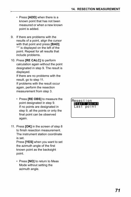
71
14. RESECTION MEASUREMENT
• Press [ADD] when there is a known point that has not been measured or when a new known point is added.
9. If there are problems with the results of a point, align the cursor with that point and press [BAD]. “*” is displayed on the left of the point. Repeat for all results that include problems.
10. Press [RE CALC] to perform calculation again without the point designated in step 9. The result is displayed.If there are no problems with the result, go to step 11.If problems with the result occur again, perform the resection measurement from step 3.
• Press [RE OBS] to measure the point designated in step 9. If no points are designated in step 9, all the points or only the final point can be observed again.
11. Press [OK] in the screen of step 8 to finish resection measurement. The instrument station coordinate is set.Press [YES] when you want to set the azimuth angle of the first known point as the backsight point.
• Press [NO] to return to Meas Mode without setting the azimuth angle.

14. RESECTION MEASUREMENT
72
• It is also possible to perform resection measurement by pressing [RESEC] when allocated to the Meas mode screen.
Allocating [RESEC]: "30.3 Allocating Key Functions"• Even if “inch” is selected in Config mode, standard deviation is displayed in
“feet” or "US feet" depending on the feet unit selected.

73
14. RESECTION MEASUREMENT
Only Z (height) of an instrument station is determined by the measurement.
• Known points must be measured by distance measurement only.• Between 1 and 10 known points can be measured.
PROCEDURE
1. In the second page of Meas mode screen, press [MENU], then select "Resection".
2. Select “Elevation”.
• The tilt screen is displayed if the instrument is out of level.Level the instrument.
"7. SETTING UP THE INSTRUMENT PROCEDURE Levelling on the screen"
3. Sight the first known point and press [OBS] to begin measurement. Press [STOP].The measurement results are displayed on the screen.
4. Press [YES] to use the measurement results of the first known point.
5. Input the known point. After setting the elevation for the first known point, press [NEXT] to move to the second point.
14.2 Height Resection Measurement
Resection.NEZElevation
R e s e c t i o n 1 s t P t .S
O B S
Z A140 49 15
150HAR
1 s t P t .
Z p :T g t . h : 0 . 1 0 0 mREAD REC NEXT CALC
11 . 8 9 1

14. RESECTION MEASUREMENT
74
6. If measuring two or more known points, repeat procedures 3 to 4 in the same way from the second point.
• Press {ESC} to return to the previous known point.
7. Press [CALC] to automatically start calculations after observations of all known points are completed. Instrument station elevation and standard deviation, which describes the measurement accuracy, are displayed.
8. Press [RESULT] to check the result.If there are no problems in the result, press {ESC} and go to step 11.
9. If there are problems with the results of a point, align the cursor with that point and press [BAD]. “*” is displayed on the left of the point.
10. Press [RE CALC] to perform calculation again without the point designated in step 9. The result is displayed.If there are no problems with the result, go to step 11.If problems with the result occur again, perform the resection measurement from step 3.
11. Press [OK] to finish resection measurement. Only Z (elevation) of the instrument station coordinate is set. N and E values are not overwritten.
Z
Z R E S U LT REC
1 0 . 0 0 0
0 . 0 0 2 2 mOK
1 s t 2 n d 3 r d
BAD RE_CALC RE_OBS ADD
0 . 0 0 0
- 0 . 0 0 3- 0 . 0 0 3
4 t h 0 . 0 0 2
Z

75
14. RESECTION MEASUREMENT
Resection calculation processThe NE coordinates are found using angle and distance observation equations, and the instrument station coordinates are found using the method of least squares. The Z coordinate is found by treating the average value as the instrument station coordinates.
Calculated instrumentstation coordinates setas hypothetical coordinates

14. RESECTION MEASUREMENT
76
Precaution when performing resectionIn some cases it is impossible to calculate the coordinates of an unknown point (instrument station) if the unknown point and three or more known points are arranged on the edge of a single circle.
An arrangement such as that shown below is desirable.
It is sometimes impossible to perform a correct calculation in a case such as the one below.
When they are on the edge of a single circle, take one of the following measures.
(1) Move the instrument station as close as possible to the center of the triangle.
(2) Observe one more known point which is not on the circle
(3) Perform a distance measurement on at least one of the three points.
• In some cases it is impossible to calculate the coordinates of the instrument station if the included angle between the known points is too small. It is difficult to imagine that the longer the distance between the instrument station and the known points, the narrower the included angle between the known points. Be careful because the points can easily be aligned on the edge of a single circle.
: Unknown point : Known point

77
15.SETTING-OUT MEASUREMENTSetting-out measurement is used to set out the required point. The difference between the previously input data to the instrument (the setting-out data) and the measured value can be displayed by measuring the horizontal angle, distance or coordinates of the sighted point.
The horizontal angle difference and distance difference are calculated and displayed using the following formulae.
• Setting out data can be input in various modes: coordinates, horizontal distance, slope distance, height difference and REM measurement.
• In slope distance, horizontal distance, height difference, and coordinate mode, registered coordinates can be recalled and used as setting-out coordinates. In slope distance, horizontal distance and height difference, S/H/V distances are calculated from the read in setting-out coordinate, instrument station data, instrument height, and target height.
• Setting-out measurement can be carried out effectively using the Guide light. "4.1 Parts of the Instrument" and "5.1 Basic Key Operation"
• EDM settings can be set in the Setting-out measurement menu.• If not measured or the space is left blank “Null” will be displayed.
If distance or angle of setting-out data is set to “Null” the Distance difference is automatically set to “Null”
Horizontal angle differencedHA = Horizontal angle of setting-out data - measured horizontal angle
Distance differenceDistance Displayed itemSdist: S-O S =measured slope distance - slope distance of setting-out dataHdist: S-O H =measured horizontal distance - horizontal distance of setting-
out dataVdist: S-O V =measured height difference - height difference of setting-out
data

15. SETTING-OUT MEASUREMENT
78
After setting the coordinates for the point to be set out, the SET calculates the setting-out horizontal angle and horizontal distance. By selecting the horizontal angle and then the horizontal distance setting-out functions, the required coordinate location can be set out.
• To find the Z coordinate, attach the target to a pole etc. with the same target height.
PROCEDURE
1. Press [S-O] on the third page of the Meas mode screen to display <S-O>.
2. Enter the instrument station data."13.1 Entering Instrument Station Data and Azimuth Angle PROCEDURE Reading in Registered Coordinate Data"
3. Set the azimuth angle of the backsight point.
"13.2 Setting Azimuth Angle from Backsight Coordinates" steps 2 to 6
15.1 Coordinates Setting-out Measurement

79
15. SETTING-OUT MEASUREMENT
4. Select “S-O data”. <S-O Coord> is displayed.
5. Enter the coordinates of the setting-out point.
• When [READ] is pressed, registered coordinates can be recalled and used as setting-out coordinates.
"13.1 Entering Instrument Station Data and Azimuth Angle PROCEDURE Reading in Registered Coordinate Data"
• When [ S-O] is pressed, input coordinates are calculated and displayed in "H dist" and "H ang".
6. Press [OK] to set the setting-out data.
• The tilt screen is displayed if the instrument is out of level.Level the instrument.
"7. SETTING UP THE INSTRUMENT PROCEDURE Levelling on the screen"
7. Rotate the top of the instrument until “dHA” is 0° and place the target on the sight line.
S-OStn. Orientation
ObservationEDM
S-O data
C o o r d
READ S-O OK
HH
H
READ S-O OK
40.0000

15. SETTING-OUT MEASUREMENT
80
8. Press [OBS] to begin setting-out measurement.The target and the distance of the point to be set out is displayed (S-OΔ H).
9. Move the prism forward and backward until the setting-out distance is 0m. If S-OΔH is “+”, move the prism toward yourself, if it is “-”, move the prism away from yourself.
• By pressing [← →], an arrow pointing to the left or right displays which direction the target should be moved.
← : Move the prism to left.→ : Move the prism to right.↓ : Move the prism forward.↑ : Move the prism away.
: Move the prism upward. : Move the prism downward.
When the target is within measurement range, all four arrows are displayed.
OBS S-O REC
O B S R E C

81
15. SETTING-OUT MEASUREMENT
10. Press {ESC} to return to <S-O>.
• When [READ] was used in step 5, the list of registered coordinates is restored. Continue setting-out measurement.
• [REC]: records measurement results
11. Recording method: "24. RECORDING DATA - RECORD MENU -"
OBS S-O REC

15. SETTING-OUT MEASUREMENT
82
The point to be found based on the horizontal angle from the reference direction and the distance from the instrument station.
PROCEDURE
1. Press [S-O] in the third page of the Meas mode screen to display <S-O>.
2. Enter the instrument station data."13.1 Entering Instrument Station Data and Azimuth Angle PROCEDURE Reading in Registered Coordinate Data"
3. Set the azimuth angle of the backsight point.
"13.2 Setting Azimuth Angle from Backsight Coordinates" steps 2 to 6
4. Select “S-O data.”
5. Press [ S-O] untill <S-O H> is displayed.
15.2 Distance Setting-out Measurement
C o o r d
P1READ S-O OK

83
15. SETTING-OUT MEASUREMENT
6. Press [ S-O] to select distance input mode.Each time [ S-O] is pressed: S-O Coord (coordinates), S-O H (horizontal distance), S-O S (slope distance), S-O V (height difference), S-O Ht. (REM measurement).
"15.1 Coordinates Setting-out Measurement", "15.3 REM Setting-out Measurement"
• When [READ] is pressed, registered coordinates can be recalled and used. Distance and angle are calculated using the coordinate value.
"13.1 Entering Instrument Station Data and Azimuth Angle PROCEDURE Reading in Registered Coordinate Data"
7. Set the following items.(1) Sdist/Hdist/Vdist: distance
from the instrument station to the position to be set out.
(2) H ang: included angle between the direction of the reference and the point to be set out.
• Pressing [COORD] in the second page allows you to enter the coordinates of the point to be set out.
8. Press [OK] to set the input values.
READ
S d i s t :H a n g :
S
0 . 0 0 0 m
O K
HH
H
READ S-O OK
40.0000
HH
H

15. SETTING-OUT MEASUREMENT
84
• The tilt screen is displayed if the instrument is out of level.Level the instrument.
"7. SETTING UP THE INSTRUMENT PROCEDURE Levelling on the screen"
9. Rotate the top of the instrument until “dHA” is 0° and place the target on the sight line.
10. Press [OBS] to start distance measurement. The target and the distance of the point to be set out is displayed (S-OΔH).
11. Move the prism to find the point to be set out.
12. Press {ESC} to return to <S-O>.
• When [READ] was used in step 5, the list of registered coordinates is restored. Continue setting-out measurement.
• [REC]: records measurement results
Recording method: "24. RECORDING DATA - RECORD MENU -"
OBS S-O REC

85
15. SETTING-OUT MEASUREMENT
To find a point where a target cannot be directly installed, perform REM setting-out measurement.
"12.5 REM Measurement"
PROCEDURE
1. Install a target directly below or directly above the point to be found, then use a measuring tape etc. to measure the target height (height from the survey point to the target).
2. Press [S-O] in the Meas mode screen to display <S-O>.
3. Enter the instrument station data."13.1 Entering Instrument Station Data and Azimuth Angle PROCEDURE Reading in Registered Coordinate Data"
4. Select “S-O data” and press [ S-O] until <S-O Ht.> is displayed.
5. Input height from the survey point to the position to be set out in “SO dist”.
6. After inputting the data, press [OK].
• The tilt screen is displayed if the instrument is out of level.Level the instrument.
"7. SETTING UP THE INSTRUMENT PROCEDURE Levelling on the screen"
15.3 REM Setting-out Measurement
3 . 3 0 0 m
H t .
H e i g h t :
S-O OK

15. SETTING-OUT MEASUREMENT
86
7. Press [REM] to begin REM setting-out measurement.Move the telescope to find the point to be set out.
"15.2 Distance Setting-out Measurement" steps 9 to 10
: Move the telescope near the zenith.
: Move the telescope near the nadir.
8. When the measurement is completed, press {ESC} to restore <S-O>.
REM

87
16.SETTING-OUT LINESetting-out line is used for setting out a required point at a designated distance from the baseline and for finding the distance from the baseline to a measured point.
To perform setting-out line measurement, first, define the baseline. The baseline can be defined by inputting the coordinates of, or by observing the two points. The scale factor value is the difference between the input coordinates and the observed coordinates.
• When not observing first or second points, scale factor is set to “1”.• Defined baseline can be used in both setting-out line measurement and point
projection.
PROCEDURE Defining by inputting coordinates
1. In the second page of Meas mode screen, press [MENU], then select "Set-out line".
16.1 Defining Baseline
Scale (X, Y) = Hdist’ (horizontal distance calculated from the measured value)Hdist (horizontal distance calculated from the input coordinates)
2nd Pt.
Cut
FillGrade
Z
EBaseline
Offset
LengthAzimuth
N
1st Pt.
REMResectionArea calculationSet-out line
Point projectionSet-out arc

16. SETTING-OUT LINE
88
2. Enter the instrument station data."13.1 Entering Instrument Station Data and Azimuth Angle PROCEDURE Reading in Registered Coordinate Data"
3. Select “Define baseline” in <Set-out line>.
4. Enter the first point data and press [OK].
• When [READ] is pressed, registered coordinates can be recalled and used.
"13.1 Entering Instrument Station Data and Azimuth Angle PROCEDURE Reading in Registered Coordinate Data"
5. Enter the second point data.
6. Press {FUNC}. [MEAS] is displayed.
• When not observing the first point and the second point, go to step 12.
7. Press [MEAS] on the screen of step 6 to move to observation of the first point.
Stn. OrientationDefine baselineSet-out line
Set-out line
D e f i n e 1 s t P t .N p :E p :Z p : 1 2 . 1 2 2
11 3 . 4 6 49 1 . 0 8 8
READ REC OKOBS
D e f i n e 2 n d P t .N p :E p :Z p :
READ REC OK
11 . 7 7 5
11 2 . 7 0 61 0 4 . 0 6 9
P1OBS
D e f i n e 2 n d P t .N p :E p :Z p :
MEAS
11 . 7 7 5
11 2 . 7 0 61 0 4 . 0 6 9
P2

89
16. SETTING-OUT LINE
8. Sight the first point and press [OBS].The measurement results are displayed on the screen.
• Press [STOP] to stop the measurement.
• You can input target height here.• The tilt screen is displayed if the
instrument is out of level.Level the instrument.
"7. SETTING UP THE INSTRUMENT PROCEDURE Levelling on the screen"
9. Press [YES] to use the measurement results of the first point.
• Press [NO] to observe the first point again.
10. Sight the second point and press [OBS].
11. Press [YES] to use the measurement results of the second point.The distance between the two measured points, the distance calculated from inputting the coordinates of two points and the scale factors are displayed.
M e a s u r e 1 s t P t .
OBS
1 2 . 1 2 2
11 3 . 4 6 49 1 . 0 8 8
N p :E p :Z p :
Measure 1st Pt.
NO YESTgt.h 1.400m
G r a d e
1:** % OK
% - 2 . 6 6 9
A z m t h 9 3 ° 2 0 ′ 3 1 ″H c a l cH m e a sS c a l e X
Sy=1 Sy=Sx OK
1.000091
13.003m
S c a l e Y 1.000091

16. SETTING-OUT LINE
90
12. Press [OK] on the screen of step 11 to define the baseline. <Set-out line> is displayed. Move to setting-line measurement.
"16.2 Setting-out Line Point"/"16.3 Setting-out Line Line"
• Press [Sy=1] to set scale factor y to “1”.
• Press [1 : **] to change the grade display mode to “1 : * * = elevation : horizontal distance”.
• It is also possible to perform setting-out line measurement by pressing [S-O LINE] when allocated to the Meas mode screen.
Allocating [S-O LINE]: "30.3 Allocating Key Functions".
PROCEDURE Defining by observation
1. In the second page of Meas mode screen, press [MENU], then select "Set-out line".
2. Enter the instrument station data."13.1 Entering Instrument Station Data and Azimuth Angle PROCEDURE Reading in Registered Coordinate Data"
3. Select “Define baseline” in <Set-out line>.
4. Sight the first point and press [OBS].
• Press [STOP] to stop the measurement.
S e t - o u t l i n eP o i n tL i n e
D e f i n e 1 s t P t .N p :E p :Z p : 0 . 0 0 0
0 . 0 0 00 . 0 0 0
READ REC OKOBS

91
16. SETTING-OUT LINE
• The tilt screen is displayed if the instrument is out of level.Level the instrument.
"7. SETTING UP THE INSTRUMENT PROCEDURE Levelling on the screen"
5. Press [OK] to use the measurement results of the first point.
• Press [OBS] to observe the first point again.
• Press [HT] to input instrument and target height.
6. Sight the second point and press [OBS].
7. Press [OK] to use the measurement results of the second point.
• Press [OBS] to observe the second point again.
• Press [HT] to input instrument and target height.
• Scale factor settings can be set in the screen shown at right.
9
HT
1 2 . 1 2 2
11 3 . 4 6 49 1 . 0 8 8
N p :E p :Z p :
REC OBS OK
Z AH A R
D e f i n e 2 n d P t .N p :E p :Z p :
READ REC OK
0 . 0 0 0
0 . 0 0 00 . 0 0 0
OBS
9
HT
1 3 . 2 1 2
11 3 . 4 6 41 4 5 . 8 7 4
N p :E p :Z p :
REC OBS OK
Z AH A R
G r a d e
1:** % OK
% - 2 . 6 6 9
A z m t h 9 3 ° 2 0 ′ 3 1 ″H c a l cH m e a sS c a l e X
Sy=1 Sy=Sx OK
1.000091
13.003m
S c a l e Y 1.000091

16. SETTING-OUT LINE
92
8. Press [OK] on the third screen of step 7 to define the baseline. <Set-out line> is displayed. Move to setting-line measurement.
"16.2 Setting-out Line Point"/"16.3 Setting-out Line Line"
• Press [Sy=1] to set scale factor y to “1”.
• Press [1 : **] to change the grade display mode to “1 : * * = elevation : horizontal distance”.
• It is also possible to perform setting-out line measurement by pressing [S-O LINE] when allocated to the Meas mode screen.
Allocating [S-O LINE]: "30.3 Allocating Key Functions".
S e t - o u t l i n eP o i n tL i n e

93
16. SETTING-OUT LINE
Setting-out line point measurement can be used to find the required point coordinate by inputting the length and offset based on the baseline.
• Before performing setting-out line point, the baseline must be defined.
PROCEDURE
1. Select “Point” in <Set-out line>
2. Set the following items. (1) Incr: Increment by which line
length and offset can be increased/decreased using the arrow softkeys.
(2) Line: Distance along the baseline from the first point to the position at which a line extending from the required point intersects the baseline at right angles (X direction).
(3) Offset: Distance from the required point to the position at which a line extending from the required point intersects the baseline at right angles (Y direction).
• [ ]/[ ]: Press to decrease/increase the value by the amount set in "Incr".
16.2 Setting-out Line Point
Baseline1st Pt.
Length
X direction
Y direction
Offset
Required point
2nd Pt.
S e t - o u t l i n eP o i n tL i n e
S e t - o u t l i n e
L i n eO f f s e t
0 . 0 0 0 m
OK
I n c r 1 . 0 0 0 m
0 . 0 0 0 m
OFFSET

16. SETTING-OUT LINE
94
3. Press [OK] on the screen of step 2. The coordinate value of the required point is calculated and displayed.
• [REC]: records the coordinate value as a known point data.
Recording method: "26.1 Registering/Deleting Known Point Data"
• Press [ S-O] to move to setting-out measurement of the required point.
"15. SETTING-OUT MEASUREMENT"
4. Press {ESC}. Continue the measurement (repeat steps from 2).
S e t - o u t l i n e
12.02494.675
R E C S - O
NEZ
111.796

95
16. SETTING-OUT LINE
PROCEDURE Offsetting the baseline
The baseline can be offset in three dimensions using four methods: lengthwise offset, lateral offset, height offset ,and rotation angle offset.
1. Select “Point” in <Set-out line>
2. Press [OFFSET] to display <Baseline offset>.
N
EN
E
N
E
N
E
N
E
30
N
E
Lengthwise offset
Lateral offset Rotation angle offset
Heightoffset
S e t - o u t l i n eP o i n tL i n e
S e t - o u t l i n e
L i n eO f f s e t
0 . 0 0 0 m
OK
I n c r 1 . 0 0 0 m
0 . 0 0 0 m
OFFSET

16. SETTING-OUT LINE
96
3. Set the following items. (1) Incr: Increment by which
offsets can be increased/decreased using the arrow softkeys.
(2) Length: Lengthwise offset(3) Lateral: Lateral offset(4) Height: Elevation offset(5) Rt.ang: Rotation angle offset• [ ]/[ ]: Press to increase/
decrease the value by the amount set in "Incr".
4. Press [OK] to return to the screen in step 2. • [MOVE]: Permanently moves
the baseline coordinates by the amount set in <Baseline offset>.
5. Press [OK] on the screen of step 2. The coordinate value of the required point is calculated, taking into account the movement of the baseline, and displayed.
B a s e l i n e o f f s e t
L e n g t hL a t e r a l
0 . 0 0 0 m
OK
I n c r 1 . 0 0 0 m
0 . 0 0 0 m
MOVEH e i g h t 0 . 0 0 0 m
OK
R t . a n g 0 . 0 0 0 0
MOVE
S e t - o u t l i n e
9.662102.482
R E C S - O
NEZ
185.675

97
16. SETTING-OUT LINE
Setting-out line line measurement tells how far horizontally the measured point is from the baseline and how far vertically the measured point is from the connected line. The baseline can be offset in a horizontal direction if necessary.• Before performing setting-out line line, the baseline must be defined.
PROCEDURE
1. Select “Line” in <Set-out line>.
2. Enter the offset value.
• Offset: How much to move the baseline.A positive value indicates right side and a negative value indicates left side.
• When not setting offset value, go to step 3.
16.3 Setting-out Line Line
Baseline
Measured Point
Offset (horizontal direction)
Offline (--)
Length
1st Pt.
2nd Pt.
Measured Point
Cut
Profile View
S e t - o u t l i n eP o i n tL i n e
S e t - o u t l i n e
O f f s e t 0 . 0 0 0 m
OBS

16. SETTING-OUT LINE
98
3. Sight the target and press [OBS] on the screen of step 2. The measurement results are displayed on the screen.Press [STOP] to stop the measurement.
• The tilt screen is displayed if the instrument is out of level.Level the instrument.
"7. SETTING UP THE INSTRUMENT PROCEDURE Levelling on the screen"
4. Press [YES] to use the measurement results. Displays the difference between the measured point and the baseline.
• Offline: A positive value indicates the point is on the right of the baseline and a negative value indicates it is on the left.
• “Cut” indicates that the point is below the baseline.
• “Fill” indicates that the point is above the baseline.
• Length: Distance along the baseline from the first point to the measured point.
• Press [NO] to observe the target again.
5. Sight the next target and press [OBS] to continue the measurement.
• Press [REC]: records measurement results.
Recording method: "24. RECORDING DATA - RECORD MENU -"
Set-out line
NO YESTgt.h 1.400m
S e t - o u t l i n e
0.006m-0.004m
R E C O B S
OfflineCut
12.917mLength

99
17.SETTING-OUT ARCThis mode allows the operator to define an arc from various arc parameters, such as From Pt. coordinates, and set out this arc as well as points (offsets) along it.
An arc can be defined by inputting arc parameters such as arc radius, angle, coordinates for the From point, Center point, To point etc. An arc can also be defined by observation of the From point, Center point, To point etc.
PROCEDURE Defining by inputting coordinates
1. In the second page of the Meas mode screen, press [MENU], then select "Set-out arc".
2. Enter the instrument station data. "13.1 Entering Instrument
Station Data and Azimuth Angle PROCEDURE Reading in Registered Coordinate Data"
17.1 Defining an Arc
To Pt.
Offset
Tangent length
From Pt.
Radius
IntersectionPt.
Bac
k ta
ngen
t
Angle
Direction
Center Pt.
R E MR e s e c t i o nA r e a c a l c u l a t i o nS e t - o u t l i n e
P o i n t p r o j e c t i o nS e t - o u t a r c
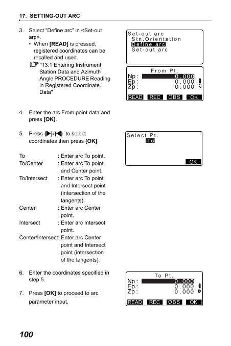
17. SETTING-OUT ARC
100
3. Select “Define arc” in <Set-out arc>. • When [READ] is pressed,
registered coordinates can be recalled and used.
"13.1 Entering Instrument Station Data and Azimuth Angle PROCEDURE Reading in Registered Coordinate Data"
4. Enter the arc From point data and press [OK].
5. Press { }/{ } to select coordinates then press [OK].
To : Enter arc To point.To/Center : Enter arc To point
and Center point.To/Intersect : Enter arc To point
and Intersect point (intersection of the tangents).
Center : Enter arc Center point.
Intersect : Enter arc Intersect point.
Center/Intersect: Enter arc Center point and Intersect point (intersection of the tangents).
6. Enter the coordinates specified in step 5.
7. Press [OK] to proceed to arc parameter input.
F r o m P t .
READ REC OKOBS
S e t - o u t a r c
S e t - o u t a r c
S t n . O r i e n t a t i o nD e f i n e a r c
S e l e c t P t .
OK
T o
To P t .
READ REC OKOBS

101
17. SETTING-OUT ARC
• When entering multiple coordinates, [NEXT] is displayed instead of [OK]. Press [NEXT] to input data for the next point.
8. Enter other arc parameters.(1) Direction (whether the arc
turns right/left from the From point)
(2) Radius (radius of the arc)(3) Angle (subtended angle)(4) Arc (distance along the arc)(5) Chord (straight line distance
between the From and To points)
(6) Tan ln (tangent length)(7) Bk tan (back tangent length)
Parameters that can be entered may be restricted depending on the coordinates specified in step 5.
" Specifying coordinates and curve parameters"
9. Enter curve parameters then press { }. Other parameters will be calculated.• [TO]: Calculated coordinates for
To point can be recorded.[CENTER]: Calculated coordinates for Center point can be recorded.[INTSCT]: Calculated coordinates for Intersect point can be recorded.
10. Press [OK] on the screen of step 9 to define the arc. <Set-out arc> is displayed. Move to setting-out arc measurement.
D i r e c t i o n : L e f tR a d i u s : < N u l l >
: < N u l l >: < N u l l >: 1 4 1 . 4 2 1 m
A n g l eA r cC h o r d
OK
Ta n I n :B k t a n : < N u l l >
OK
< N u l l >
D i r e c t i o n : R i g h tR a d i u sA n g l eA r c : 1 5 7 . 0 8 0 mC h o r d : 1 4 1 . 4 2 1 m
OK
: 1 0 0 . 0 0 0 m: 9 0 0 0 ’ 0 0 "
INTSCT

17. SETTING-OUT ARC
102
"17.2 Setting-out Arc" step 2
• It is also possible to perform setting-out arc measurement by pressing [S-O ARC] when allocated to the Meas mode screen.
Allocating [S-O ARC]: "30.3 Allocating Key Functions"
PROCEDURE Defining by observation
1. In the second page of Meas mode screen, press [MENU], then select "Set-out arc".
2. Enter the instrument station data."13.1 Entering Instrument Station Data and Azimuth Angle PROCEDURE Reading in Registered Coordinate Data"
3. Select “Define arc” in <Set-out arc>.
4. Sight the From point and press [OBS].
• Press [STOP] to stop the measurement.
• The tilt screen is displayed if the instrument is out of level.Level the instrument.
"7. SETTING UP THE INSTRUMENT PROCEDURE Levelling on the screen"
F r o m P t .
READ REC OKOBS

103
17. SETTING-OUT ARC
5. Press [OK] to use the measurement results of the From point.
• Press [OBS] to observe the first point again.
• Press [HT] to input instrument and target height.
6. Press { }/{ } to select coordinates then press [OK].
7. Sight the To/Center/Intersect point and press [OBS].
8. Press [OK] to use the measurement results of the To/Center/Intersect point.
• Press [OBS] to observe the second point again.
• Press [HT] to input instrument and target height.
• When entering multiple points, [NEXT] is displayed instead of [OK]. Press [NEXT] to observe the next point.
9
HT
1 2 . 1 2 2
11 3 . 4 6 49 1 . 0 8 8
N p :E p :Z p :
REC OBS OK
Z AH A R
S e l e c t P t .
OK
T o
To P t .
READ REC OKOBS
9
HT
1 2 . 1 2 2
11 3 . 4 6 49 1 . 0 8 8
N p :E p :Z p :
REC OBS OK
Z AH A R

17. SETTING-OUT ARC
104
9. Enter other arc parameters.(1) Direction (whether the arc
turns right/left from the From point)
(2) Radius (radius of the arc)(3) Angle (subtended angle)(4) Arc (distance along the arc)(5) Chord (straight line distance
between the From and To points)
(6) Tan ln (tangent length)(7) Bk tan (back tangent length)
Parameters that can be entered may be restricted depending on the coordinates specified in step 5.
" Specifying coordinates and curve parameters"
10. Enter curve parameters then press { }. Other parameters will be calculated.• [TO]: Observation data for To
point can be recorded.[CENTER]: Observation data for Center point can be recorded.[INTSCT]: Observation data for Intersect point can be recorded.
11. Press [OK] on the screen of step 10 to define the arc. <Set-out arc> is displayed. Move to setting-out arc measurement.
"17.2 Setting-out Arc" step 2
• It is also possible to perform setting-out arc measurement by pressing [S-O ARC] when allocated to the Meas mode screen.
Allocating [S-O ARC]: "30.3 Allocating Key Functions"
D i r e c t i o n : L e f tR a d i u s : < N u l l >
: < N u l l >: < N u l l >: 1 4 1 . 4 2 1 m
A n g l eA r cC h o r d
OK
Ta n I n :B k t a n : < N u l l >
OK
< N u l l >
D i r e c t i o n : R i g h tR a d i u sA n g l eA r c : 1 5 7 . 0 8 0 mC h o r d : 1 4 1 . 4 2 1 m
OK
: 1 0 0 . 0 0 0 m: 9 0 0 0 ’ 0 0 "
INTSCT

105
17. SETTING-OUT ARC
Specifying points and curve parametersParameters that can be entered may be restricted depending on the points spec-ified in step 5/6. Parameters that can be entered are marked with a circle ( ○ ).Those that cannot are marked with a cross ( × ).
Precaution when performing setting-out arcIn the following cases parameters cannot be calculated:
when Radius<
When Arc<Chord
When Tan In × 2<Chord
When the included angle between the back tangent and the azimuth anglebetween the From Pt. and To Pt is 0°, or exceeds 180°.
Parameters
Setcoord
Radius Angle Arc Chord Tan In Bk tan
Direction
To pt
Center pt
× × × × × × ○
To pt
Intersect pt
× × × × × × ○
Center pt
Intersect pt
× × × × × × ○
To pt ○ ○ ○ × ○ ○ ○
Center pt × ○ ○ ○ ○ × ○
Intersect pt ○ ○ × ○ × × ○
Chord2
------------------

17. SETTING-OUT ARC
106
Setting-out arc measurement can be used to find the coordinates of requiredpoints along the arc by inputting the arc (or chord) length and offset based on thearc.
• Before performing setting-out arc, the arc must be defined.
PROCEDURE
1. Select “Set-out arc” in <Set-out arc>.
2. Set the following items.(1) Incr: Increment by which
values can be increased/decreased using the arrow softkeys.
(2) Arc: Distance along the defined arc from the From point to the required point.
(2)’ Chord: Distance along the chord of the defined arc from the From point to the required point.
(3) Offset: Distance from the required point to the position on a curve parallel to the original defined arc. A positive value indicates an offset arc to the right, and a negative value indicates an arc to the left.
17.2 Setting-out Arc
Chord Arc
Offset
S e t - o u t a r c
S e t - o u t a r cS t n . O r i e n t a t i o nD e f i n e a r c
: 1 . 0 0 0 mS e t - o u t a r c
A r cO f f s e t : 5 . 0 0 0 m
OKCHORD
I n c r
P1

107
17. SETTING-OUT ARC
• Press [CHORD] to switch to Chord input.
• [ ]/[ ]: Press to decrease/increase the value by the amount set in "Incr".
3. Press [OK] on the screen of step 2. The coordinate value of the required point is calculated and displayed.
• [REC]: records the coordinate value as a known point data.
Recording method: "26.1 Registering/Deleting Known Point Data"
• Press [ S-O] to move to setting-out measurement of the required point.
"15. SETTING-OUT MEASUREMENT"
4. Press {ESC}. Continue the measurement (repeat steps from 2).
S e t - o u t a r c
C h o r dO f f s e t : 0 . 0 0 0 m
: 0 . 0 0 0 m
OKARCP1
: 1 . 0 0 0 mI n c r
S e t - o u t a r c
EN
Z
11 8 . 8 7 41 0 6 . 8 9 4
1 2 . 5 4 6
S-OREC

17. SETTING-OUT ARC
108
PROCEDURE Offsetting the arcline
The arcline can be offset in three dimensions using four methods: lateral offset, rotation angle offset, lengthwise offset, and height offset.
1. Select “Set-out arc” in <Set-out arc>.
2. Press {FUNC}, and then press [OFFSET] to display <Arcline offset>.
3. Set the following items. (1) Incr: Increment by which
offsets can be increased/decreased using the arrow softkeys.
(2) Length: Lengthwise offset(3) Lateral: Lateral offset(4) Height: Elevation offset(5) Rt.ang: Rotation angle offset• [ ]/[ ]: Press to decrease/
increase the value by the amount set in "Incr".
N
E
N
E
N
E
N
E
N
E
N
E
30
N
E
N
E
Lengthwise offset
Lateral offset Rotation angle offset
Heightoffset
: 1 . 0 0 0 mS e t - o u t a r c
A r cO f f s e t : 5 . 0 0 0 m
OFFSET
I n c r
P2
A r c l i n e o f f s e t
L e n g t hL a t e r a l
0 . 0 0 0 m
OK
I n c r 1 . 0 0 0 m
0 . 0 0 0 m
MOVEH e i g h t 0 . 0 0 0 m
OK
R t . a n g 0 . 0 0 0 0
MOVE

109
17. SETTING-OUT ARC
4. Press [OK] to return to the screen in step 2. • [MOVE]: Permanently moves
the baseline coordinates by the amount set in <Arcline offset>.
5. Press [OK] on the screen of step 2. The coordinate value of the required point is calculated, taking into account the movement of the arcline, and displayed.
S e t - o u t a r c
EN
Z
11 8 . 8 7 41 0 6 . 8 9 4
1 2 . 5 4 6
S-OREC

110
18.POINT PROJECTIONPoint projection is used for projecting a point onto the baseline. The point to project can be either measured or input. Displays the distances from the first point and point to project to the position at which a line extending from point to project intersects the baseline at right angles.
• Defined baseline can be used in both setting-out line measurement and point projection.
PROCEDURE
1. In the second page of Meas mode screen, press [MENU], then select "Point Projection".
2. Enter the instrument station data then define the baseline.
"16.1 Defining Baseline" step 2 to 13
3. Press [OK] to define the baseline. <Point projection> is displayed. Move to point projection measurement.
"18.2 Point Projection"
18.1 Defining Baseline
Y direction
X direction
1st Pt.Length Offset
Point to project
Baseline2nd Pt.
REMResectionArea calculationSet-out line
Point projectionSet-out arc
P o i n t p r o j e c t i o nN p :E p :Z p :
READ REC OK
1 2 . 1 5 2
1 0 3 . 5 1 41 0 1 . 4 2 3
OBS

111
18. POINT PROJECTION
• It is also possible to perform setting-out line measurement by pressing [P-PROJ] when allocated to the Meas mode screen.
Allocating the function key: "30.3 Allocating Key Functions"
Before performing point projection, the baseline must be defined.
PROCEDURE
1. Define the baseline."18.1 Defining Baseline"
2. Select "Point Projection" in <Point Projection>.
3. Enter the point coordinate.
• Press [OBS] to observe the point to project.
• The tilt screen is displayed if the instrument is out of level.Level the instrument.
"7. SETTING UP THE INSTRUMENT PROCEDURE Levelling on the screen"
• Press [REC] to record the data as a known point.
Recording method: "26.1 Registering/Deleting Known Point Data"
18.2 Point Projection
Stn. OrientationDefine baselinePoint projection
Point projection
P o i n t p r o j e c t i o nN p :E p :Z p :
READ OBS OK
1 2 . 1 5 2
1 0 3 . 5 1 41 0 1 . 4 2 3
P1

18. POINT PROJECTION
112
4. Press [OK] on the screen of step 3. The following items are calculated and displayed.
• Length: Distance along the baseline from the first point to the projected point (X direction).
• Offset: Distance from point to project to the position at which a line extending from point of project intersects the baseline at right angles. (Y direction).
• d.Elev: Elevation between the baseline and the projected point.
• Press [XYZ] to switch the screen display to coordinate values.
• Press [OFFSET] to switch the screen display to distance values.
• Press [REC]: records the coordinate value as a known point data.
Recording method: "26.1 Registering/Deleting Known Point Data"
• Press [ S-O] to move to setting-out measurement of the projected point.
"15. SETTING-OUT MEASUREMENT"
5. Press {ESC}. Continue the measurement (repeat steps from 3).
P o i n t p r o j e c t i o nL e n g t hO f f s e td . E l e v
XYZ REC S-O
0 . 3 2 1 m
1 0 . 8 7 9 m9 . 3 4 0 m

113
19. INTERSECTIONSIt is possible to find an intersection point between 2 reference points by specify-ing the length or azimuth angle of either point.
PROCEDURE
1. In the second page of the Meas mode screen, press [MENU], then select "Intersections".
2. Enter the 1st point data and press [NEXT].
Intersection Pt.1
Intersection Pt.2
2nd Pt.Azimuth 1
1st Pt.
Hdist 2
Intersection Pt. 1
2nd Pt.
1st Pt.
Hdist 2
Intersection Pt. 2
Hdist 1
I n t e r s e c t i o n sT r a v e r s e
D e f i n e 1 s t P t .
Ep:Np:
Zp:
11 3 . 4 6 4
1 2 . 1 2 29 1 . 0 8 8
RECREAD NEXTOBS

19. INTERSECTIONS
114
• When [READ] is pressed, registered coordinates can be recalled and used.
"13.1 Entering Instrument Station Data and Azimuth Angle PROCEDURE Reading in Registered Coordinate Data"
• [REC]: records the coordinate value as a known point data.
• Press [OBS] to observe the selected point.
• The tilt screen is displayed if the instrument is out of level.Level the instrument.
"7. SETTING UP THE INSTRUMENT PROCEDURE Levelling on the screen"
3. Enter the 2nd point data and press [OK].
• Press [OBS] to observe the selected point.
4. Enter azimuth angle (or horizontal distance) of the 1st point and 2nd point.
:Both the azimuth angle and horizontal distance of the 1st (or 2nd) point cannot be input.
113.46491.08812.122
D e f i n e 2 n d P t .
Ep:Np:
Zp:
11 2 . 7 0 61 0 4 . 0 6 9
11 . 7 7 5
OKRECREAD OBS
: 5 0 . 0 0 0 m
A z m t h 1H . d i s t 1A z m t h 2H . d i s t 2
OK
: < N u l l >: 4 5 0 0 ’ 0 0 "
COORD

115
19. INTERSECTIONS
• When the cursor is on "Azmth1" or "Azmth2", [COORD] is displayed. Press [COORD] to set the azimuth angle for each point by inputting coordinates.
• Press [OBS] to observe the selected point.
5. Press [OK]. The coordinate value of the intersection point is calculated and displayed.
• When there are 2 intersections, [OTHER] is displayed.
" 2 Intersections"
• Press [ S-O] to move to setting-out measurement of the required point.
"15. SETTING-OUT MEASUREMENT"
6. Press {ESC}. Continue the measurement (repeat steps from 2).
• It is also possible to perform intersection measurement by pressing [INTSCT] when allocated to the Meas mode screen.
Allocating [INTSCT]: "30.3 Allocating Key Functions"
2 Intersections2 intersections are defined according to 1st Pt. and 2nd Pt. as shown belowIntersections created from Azmth 1 and H.dist 2 (or H.dist 1 and Azmth 2):
1 s t P t .
E p :N p :
Z p :
0 . 0 0 00 . 0 0 0
< N u l l >
NEXTRECREAD OBS
A z m t h 1H . d i s t 1A z m t h 2H . d i s t 2
OK
: < N u l l >: < N u l l >: 5 0 . 0 0 0 m
: 4 5 0 0 ’ 0 0 "
I n t e r s e c t i o n 1
EN
Z
1 7 6 . 4 5 81 7 6 . 4 5 8
< N u l l >
S-ORECOTHER
19. INTERSECTIONS
116
An azimuth angle has already been set for a point. The furthest point from this point is set as Intersection Pt. 1, and the closest point set as Intersection Pt. 2.
• Intersections created from H.dist 1 and H.dist 2:Intersection to the right of the straight line between 1st point and 2nd point set as Intersection Pt. 1 and the point to the left set as Intersection Pt. 2.
Precaution when performing intersection measurementIn the following cases the coordinates of intersection points cannot be calculated.
When Azimuth 1 = Azimuth 2.When Azimuth 1 – Azimuth 2 = ±180°.When H.dist 1 = 0, or H.dist 2 = 0.When the coordinates for 1st Pt. and 2nd Pt are the same.

117
20.TRAVERSE ADJUSTMENTMeasurement of a traverse begins with observation of the backsight station and foresight station. The instrument station is then moved to the foresight station and the previous instrument station becomes the backsight station. Observation is performed again at the new position. This process is repeated for the length of the route.This adjustment function is used to calculate the coordinates of such a sequence of consecutively-observed points (traverse points and points observed from traverse points (see P3-1 to P3-3 below)). When calculation is complete, the SET displays the precision of the traverse and, when necessary, traverse adjustment can be performed.
For types of traverse that can be calculated with the SET, see " Types of traverse”
PROCEDURE
1. Before starting traverse calculation, observe the sequence of traverse points and record the results.
"24.4 Recording Distance Measurement Data"/"24.6 Recording Distance and Coordinate Data"
2. In the second page of the Meas mode screen, press [MENU], then select "Traverse".
P7
P5
P4P3
P2
P1
Start Pt.
P6
Backsight Station
Azimuthangle
End Pt.
P3-1P3-2
P3-3
I n t e r s e c t i o n sT r a v e r s e

20. TRAVERSE ADJUSTMENT
118
3. Enter the start point name and press { }.
• When [LIST] is pressed, a list of instrument stations saved in the current JOB is displayed. A point from this list can be recalled and used.
For using softkeys in this screen, see "13.1 Entering Instrument Station Data and Azimuth Angle PROCEDURE Reading in Registered Coordinate Data"
• Enter values manually when there are no coordinates saved for the specified instrument station.Press [OK] to proceed to step 4.
4. Enter the point name of the backsight station for the start point and press { }.
T r a v e r s e s t a r t p t .
B s :S t n :
A z m t h : < N u l l >OKLIST
S t n T - 0 0 0 1S t n T - 0 0 0 2S t n T - 0 0 0 3S t n T - 0 0 0 4S t n T - 0 0 0 5
SRCHLASTTOP...P
READ
Stn:
<Null>
REC OKPt. T-0001
T r a v e r s e s t a r t p t .
B s :S t n : T - 0 0 0 1
A z m t h : < N u l l >OKLIST
B S

119
20. TRAVERSE ADJUSTMENT
When there are saved coordinates for the backsight station, the calculated azimuth angle is displayed.
• Enter values manually when there are no coordinates saved for the specified start point backsight station.Press [OK] to display the calculated azimuth angle.
• To enter azimuth angle without entering backsight station coordinates, press { } to move the cursor down to "Azmth" then enter an angle value.
5. When [OK] is pressed in the screen in step 4, the SET will search for a traverse route. The points from step 1 will be displayed in the order in which they were observed.
• This search can be stopped by pressing {ESC}. If {ESC} is pressed, a route can be computed using only the points found prior to the search being stopped.
• When a traverse point with recorded known point coordinates is found, or there are multiple foresight stations for a point, the automatic route search will stop. Press [LIST] and select which foresight station to use as the next point.
" Automatic route search"
T r a v e r s e s t a r t p t .
B s : T - 0 0 0 ZS t n : T - 0 0 0 1
A z m t h :OK
3 5 7 2 7 ’ 4 6 "
0 0 1 : T - 0 0 0 1
S e a r c h i n g
E x i t S e a r c h i n g
c o n f i r m ?
YESNO

20. TRAVERSE ADJUSTMENT
120
6. Press [OK] to confirm the traverse route.
7. Enter the point name of the backsight station for the end point and press { }.The calculated azimuth angle is displayed.
Enter the azimuth angle when there are no recorded coordinates for the end point backsight station.
8. When [OK] is pressed in the screen in step 7, the SET will display the precision of the traverse.
d.Ang: Angular closure errord.Dist: Horizontal closure
distancePrecision: Precision of the
traverse as a ratio of the total horizontal distance traversed to the closure distance
d.North: Closure distance in Northing coordinates
d.East: Closure distance in Easting coordinates
d.Elev: Closure distance in elevation
0 0 6 : T - 0 0 0 60 0 7 : T - 0 0 0 70 0 8 : T - 0 0 0 10 0 9 :
OKLIST
T r a v e r s e e n d p t .
F s : T - 0 0 0 2S t n : T - 0 0 0 1
A z m t h :OK
3 3 5 2 7 ’ 4 6 "LIST
Precis ion
T r a v e r s e p r e c i s i o n
d . A n gd . D i s t
ADJUSTOPTION
T r a v e r s e p r e c i s i o n
d . N o r t hd . E a s td . E l e v
ADJUSTOPTION
: 0 . 0 1 3: 0 . 0 0 0: - 0 . 0 0 2

121
20. TRAVERSE ADJUSTMENT
• Press [OPTION] to change the method by which the traverse adjustments are distributed.
(*:Factory setting)(1) Method (coordinate
adjustment):Compass*, Transit
(2) Angular: Weighted*, Linear, None
(3) Elev (Elevation): Weighted*, Linear, None
For all options, see " Adjustment methods"
9. Angular adjustment will be performed first. Press [ADJUST] to start adjustment using the method selected in "(2) Angular" in step 8.
• When "None" is selected in "(2) Angular" in step 8, only coordinate and elevation adjustment will be performed.
10. After confirming the results, press [ADJUST] again to start coordinate and elevation adjustment using the methods selected in "(1) Method" and "(3) Elev" respectively. All adjusted instrument data will be in saved in the currently selected JOB and traverse adjustment will be finished.
A d j u s t m e n t o p t i o n s
M e t h o dA n g u l a rE l e v
: C o m p a s s: W e i g h t e d: W e i g h t e d
A f t e r a n g l e a d j u s t
d . A n gd . D i s tp r e c i s i o n
ADJUSTOPTION
: 0 0 0 ’ 0 0 "
T r a v e r s e a d j u s t m e n t
R e c o r d i n g . . . 7

20. TRAVERSE ADJUSTMENT
122
• It is also possible to perform traverse adjustment by pressing [TRAVER] when allocated to the Meas mode screen.
Allocating [TRAVER]: "30.3 Allocating Key Functions"• Traverse adjustment results of traverse points, points observed from traverse
points and traverse adjustment data will be saved in the currently selected JOB as Notes data. Data including the distributed closure error will also be saved in the currently selected JOB as ordinary coordinate data.
Traverse line record (3): 1. point names of start and end points 2. backsight station name and azimuth to said backsight station 3. foresight station name and azimuth to said foresight
Adjustment setting record (1): The selected method for distributing closure error.
Closure error record (2x2): 1. precision and closure error for angle/distance 2. coordinate closure error
Coordinate adjustment record (No. of included points between start and end points):
Coordinates

123
20. TRAVERSE ADJUSTMENT
Types of traverse SET can calculate closed-loop and closed traverses. In both cases, the
azimuth for the start point (and for the end point in the case of a closed traverse) must be set.
Automatic route searchThis function searches for consecutively-observed traverse points already stored on the SET and presents them as potential traverse routes.
This function is activated when the following conditions are met. When a point has been observed more than once, the most recent data will be used for the search.
• At least one backsight station and one foresight station are observed from an instrument station.
• The foresight station becomes the instrument station for the subsequent measurement.
• The instrument station becomes the backsight station for the subsequent measurement.
closed-loop traverse
closed traverse

20. TRAVERSE ADJUSTMENT
124
If one of the following conditions is met, the automatic route search will terminate. The same search can be resumed by specifying the name of the next point in the route.
• There is more than one potential foresight station for an instrument station. (Route search terminates as a juncture appears in the route.)
• The foresight station for the previous measurement was the Start pt. (Route search terminates as this measurement is judged to have closed a closed-loop traverse.)
• The most recently measured point has the same point name as a recorded known point. (Route search terminates as this point is judged to be the End pt.)
The automatic route search function cannot be used in the following case.• The final measurement is to a traverse point on the traverse route other than
the Start pt.
Adjustment methodsAdjustment is applied to results for traverse points and points observed from traverse points.Adjustment methods and distribution options selected in step 8 are described below.
Method Compass: The Compass method distributes the coordinate error in
proportion to the length of the traverse lines.
Northing adjustment = closure north
Easting adjustment = closure east
Where: L =length of the traverse line to the pointTL = sum of the traverse line lengths
Transit: The Transit method distributes the coordinate error in proportion to the northing and easting ordinates of each traverse line.
Northing adjustment =| closure north
Easting adjustment = closure east
LTL------- ×
LTL------- ×
ΔNΣ ΔN--------------- ×
ΔEΣ ΔE--------------- ×

125
20. TRAVERSE ADJUSTMENT
Where: ΔN = change in northing for the traverse lineΔE = change in easting for the traverse line
Σ|ΔN| = sum of the absolute value of all the changes in northings of all the traverse lines
Σ|ΔE| = sum of the absolute value of all the changes in eastings of all the traverse lines
Angular adjustment Weighted: Any angular closure is distributed among the angles of the
traverse route based on the sum of the inverses of the forward and back traverse line lengths at each angle. The backsight and foresight lines are considered to have infinite lengths for the purposes of this weighting computation.
Linear: Any angular closure is distributed evenly among the angles of the traverse route.
None: No angular adjustment performed.
Elev adjustmentWeighted: Any closure in the elevations is distributed in proportion to the
length of the traverse line leading to the point (like the Compass method for coordinate adjustment).
Linear: Any closure in the elevations is distributed evenly in each leg of the traverse route.
None: No elevation adjustment performed.
adjustment
1todist---------------- 1
fromdist------------------------+⎝ ⎠
⎛ ⎞
Σ 1todist---------------- 1
fromdist------------------------+⎝ ⎠
⎛ ⎞--------------------------------------------------------- closure∠×=∠

126
21.OFFSET MEASUREMENTOffset measurements are performed in order to find a point where a target cannot be installed directly or to find the distance and angle to a point which cannot be sighted.
• It is possible to find the distance and angle to a point you wish to measure (target point) by installing the target at a location (offset point) a little distance from the target point and measuring the distance and angle from the survey point to the offset point.
• The target point can be found in the three ways explained below.
Finding it by entering the horizontal distance from the target point to the offset point.
• When the offset point is positioned to the left or right of the target point, make sure the angle formed by lines connecting the offset point to the target point and to the instrument station is almost 90°.
• When the offset point is positioned in front of or behind the target point, install the offset point on a line linking the instrument station with the target point.
PROCEDURE
1. Set the offset point close to the target point and measure the distance between them, then set up a prism on the offset point.
21.1 Single-distance Offset Measurement

127
20. OFFSET MEASUREMENT
2. Sight the offset point and press [DIST] in the first page of the Meas mode screen to begin measurement. The measurement results are displayed. Press [STOP] to stop the measurement.
3. Press [OFFSET] in page three of Meas mode to display <Offset>.
4. Enter the instrument station data."13.1 Entering Instrument Station Data and Azimuth Angle PROCEDURE Reading in Registered Coordinate Data".
5. Select “Offset/Dist”.
• The tilt screen is displayed if the instrument is out of level.Level the instrument.
"7. SETTING UP THE INSTRUMENT PROCEDURE Levelling on the screen"
6. Input the following items. (1) Horizontal distance from the
target point to the offset point.(2) Direction of the offset point.
• Direction of offset point
• Press [OBS] to re-observe the offset point.
← : On the left of the target point.→ : On the right of the target
point.↓ : Closer than the target point.↑ : Beyond the target point.
OKOBS
2.000
Stn. OrientationOffset/DistOffset/AngleOffset/2D
Offset

20. OFFSET MEASUREMENT
128
7. Press [OK] on the screen of step 5 to calculate and display the distance and angle of the target point.
8. Press [YES] to return to <Offset>.
• Press [XYZ] to switch the screen display from distance values to coordinate values. Press [HVD] to return to distance values.
• Press [NO] to return to the previous distance and angle.
• To record the calculation result, press [REC].
"24. RECORDING DATA - RECORD MENU -"
Sighting the direction of the target point to find it from the included angle.Install offset points for the target point on the right and left sides of and as close as possible to the target point and measure the distance to the offset points and the horizontal angle of the target point.
21.2 Angle Offset Measurement

129
20. OFFSET MEASUREMENT
PROCEDURE
1. Set the offset points close to the target point (making sure the distance from the instrument station to the target point and the height of the offset points and the target point are the same), then use the offset points as the target.
2. Sight the offset point and press [DIST] in the first page of the Meas mode screen to begin measurement. The measurement results are displayed. Press [STOP] to stop the measurement.
3. Press [OFFSET] in page three of Meas mode to display <Offset>.
4. Enter the instrument station data."13.1 Entering Instrument Station Data and Azimuth Angle PROCEDURE Reading in Registered Coordinate Data"
5. Select “Offset/Angle” in <Offset>.
• The tilt screen is displayed if the instrument is out of level.Level the instrument.
"7. SETTING UP THE INSTRUMENT PROCEDURE Levelling on the screen"
6. Accurately sight the direction of the target point and press [OK].The distance and angle of the target point are displayed.
Stn. OrientationOffset/DistOffset/AngleOffset/2D
Offset

20. OFFSET MEASUREMENT
130
7. After finishing measurement, press [YES] to return to <Offset>.
By measuring the distances between the target point and the two offset points.Install two offset points (1st target and 2nd target) on a straight line from the target point, observe the 1st target and 2nd target, then enter the distance between the 2nd target and the target point to find the target point.
• It is possible to make this measurement easily using the optional equipment: the 2-point target (2RT500-K). When using this 2-point target, be sure to set prism constant to 0.
"30.1 EDM Settings"
How to use 2-point target (2RT500-K)
• Install the 2-point target with its tip at the target point.• Face the targets toward the instrument.• Measure the distance from the target point to the 2nd target.• Set the reflector type to “sheet”.
21.3 Two-distance Offset Measurement
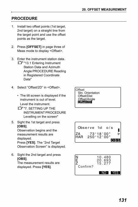
131
20. OFFSET MEASUREMENT
PROCEDURE
1. Install two offset points (1st target, 2nd target) on a straight line from the target point and use the offset points as the target.
2. Press [OFFSET] in page three of Meas mode to display <Offset>.
3. Enter the instrument station data."13.1 Entering Instrument Station Data and Azimuth Angle PROCEDURE Reading in Registered Coordinate Data"
4. Select “Offset/2D” in <Offset>.
• The tilt screen is displayed if the instrument is out of level.Level the instrument.
"7. SETTING UP THE INSTRUMENT PROCEDURE Levelling on the screen"
5. Sight the 1st target and press [OBS]. Observation begins and the measurement results are displayed.Press [YES]. The “2nd Target Observation Screen” is displayed.
6. Sight the 2nd target and press [OBS]. The measurement results are displayed. Press [YES].
Stn. OrientationOffset/DistOffset/AngleOffset/2D
Offset
O B S
1st
Confirm?

20. OFFSET MEASUREMENT
132
7. Enter the distance from the 2nd target to the target point and press { }. The coordinates of the target point are displayed.
8. Press [YES]. <Offset> is restored.
• When [HVD] is pressed, display mode is switched from coordinates to S, ZA, HAR.
0 0 0

133
22.MISSING LINE MEASUREMENTMissing line measurement is used to measure the slope distance, horizontal distance, and horizontal angle to a target from the target which is the reference (starting point) without moving the instrument.
• It is possible to change the last measured point to the next starting position.• Measurement result can be displayed as the gradient between two points.
The distance between two or more points can either be measured by observing the targets in question or calculating from input coordinates. A combination of these two methods (e.g. observing the 1st target and inputting 2nd target coordinates) is also possible.
22.1 Measuring the Distance between 2 or more Points

22. MISSING LINE MEASUREMENT
134
PROCEDURE Measuring using observation
1. In the third page of Meas mode screen, press [MLM], then select "MLM".
2. Sight the 1st target and press [OBS].
• The tilt screen is displayed if the instrument is out of level.Level the instrument.
"7. SETTING UP THE INSTRUMENT PROCEDURE Levelling on the screen"
3. Sight the second target and press [MLM] to begin observation.
• [REC]: records 1st target measurement results.
The following values are displayed:S : Slope distance of the starting
position and 2nd target.H : Horizontal distance of the
starting position and 2nd position.
V : Height difference of the starting position and 2nd target.
• Target height of the starting position and 2nd target can be input. Press [TARGET] on the second page.
Input the target heights and press [OK].
MLMStn.OrientationMLM
1515
804242
140 P1
Set Pt.1SZAHAR
1515
804242
140 P1
Set Pt.2SZAHAR
0.123m
REC
P1REC
P2TARGETS/%COORD
Target height
P t . 2
OK
1.500mP t . 1 1.500m

135
22. MISSING LINE MEASUREMENT
• Press [COORD] to input coordinates.
"PROCEDURE Calculating from input coordinates"
• Press [REC] to record 2nd target measurement results and display the screen at right.
Press [OK] to record missing line measurement results and return to the results screen.
Press {ESC} to continue measurement without saving 2nd target or missing line measurement results.
• Missing line measurement results cannot be recorded when point names for 1st and/or 2nd target are null. Always input point names for both targets.
Cd
LISTO K ADD SRCH
N 10.000E 20.000Z
10101.500mTgt.h
30.000
Pt.1
LISTO K ADD SRCH
H 27.345mV 1.012mCd 1010
23Pt.2
P1

22. MISSING LINE MEASUREMENT
136
4. Sight the next target and press [MLM] to begin observation. Slope distance, horizontal distance and height difference between multiple points and the starting position can be measured this way.
• When [S/%] is pressed, the distance between two points (S) is displayed as the gradient between two points.
• Press [OBS] to re-observe the starting position. Sight the starting position and press [OBS].
• When [MOVE] is pressed, the last target measured becomes the new starting position to perform missing line measurement of the next target.
"22.2 Changing the Starting Point"
5. Press {ESC} to end missing line measurement.
PROCEDURE Calculating from input coordinates
1. In the third page of Meas mode screen, press [MLM], then select "MLM".
2. Press [COORD] on the second page.
MLMStn.OrientationMLM
1515
804242
140 P2
Set Pt.1SZAHAR
TARGETS/%COORD

137
22. MISSING LINE MEASUREMENT
3. Input coordinates for the 1st target and press [OK].• When you wish to read in and set
coordinate data from memory, press [READ].
"13.1 Entering Instrument Station Data and Azimuth Angle"
4. Select "Pt.2" and press { } to proceed to 2nd target input.
5. Input coordinates for the 2nd target and press [OK].The following values are displayed:S : Slope distance of the starting
position and 2nd target.H : Horizontal distance of the
starting position and 2nd position.
V : Height difference of the starting position and 2nd target.
• Target height of the starting position and 2nd target can be input. Press [TARGET] on the second page.
Input the target heights and press [OK].
20.00030.00040.000
Pt.1
RECREAD O K
1515
804242
140 P1
Set Pt.2SZAHAR
0.123m
REC
MLMPt.1Pt.2
P1REC
Target height
P t . 2
OK
1.500mP t . 1 1.500m

22. MISSING LINE MEASUREMENT
138
• Press [COORD] to re-input coordinates for the first or 2nd targets.
• [REC]: records missing line measurement results.
• When [S/%] is pressed, the distance between two points (S) is displayed as the gradient between two points.
• Press [OBS] to observe the starting position.
"PROCEDURE Measuring using observation"
• When [MOVE] is pressed, the last target measured becomes the new starting position to perform missing line measurement of the next target.
"22.2 Changing the Starting Point"
Press {ESC} to end missing line measurement
Missing line measurement results cannot be recorded when point names for 1st and/or 2nd target are null. Always input point names for both targets.

139
22. MISSING LINE MEASUREMENT
It is possible to change the last measured point to the next starting position.
PROCEDURE
1. Observe the starting position and target. "22.1 Measuring the
Distance between 2 or more Points"
2. After measuring the targets, press [MOVE]. Press [YES].
• Press [NO] to cancel measurement.
22.2 Changing the Starting Point
REC
Move 1st obs ?MLM

22. MISSING LINE MEASUREMENT
140
3. The last target measured is changed to the new starting position. Perform missing line measurement.
"22.1 Measuring the Distance between 2 or more Points".

141
23.SURFACE AREA CALCULATIONYou can calculate the area of land (slope area and horizontal area) enclosed by three or more known points on a line by inputting the coordinates of the points.
• Number of specified coordinate points: 3 or more, 50 or less• Surface area is calculated by observing the points on a line enclosing an area
in order or reading in the previously registered coordinates in order.
• If two or less points are used to measure an area, an error will occur.• Be sure to observe (or recall) points on an enclosed area in a clockwise or
counterclockwise direction. For example, the area specified by entering (or recalling) point numbers 1, 2, 3, 4, 5 or 5, 4, 3, 2, 1 implies the same shape. However, if points are not entered in numerical order, the surface area will not be calculated correctly.
Slope area The first three points specified (measured/read-in) are used to create the
surface of the slope area. Subsequent points are projected vertically onto this surface and the slope area calculated.
Input OutputCoordinates : P1 (N1, E1, Z1) Surface area: S (slope area and horizontal area)
...P5 (N5, E5, Z5)

23. SURFACE AREA CALCULATION
142
PROCEDURE Surface area calculation by observing points
1. In the second Meas mode screen, press [MENU], then select "Area calculation".
2. Enter the instrument station data."13.1 Entering Instrument Station Data and Azimuth Angle PROCEDURE Reading in Registered Coordinate Data"
3. Select "Area calculation" in <Area calculation>.
4. Sight the first point on the line enclosing the area, and press [MEAS].
• The tilt screen is displayed if the instrument is out of level.Level the instrument.
"7. SETTING UP THE INSTRUMENT PROCEDURE Levelling on the screen"
5. Press [OBS] to begin observation.The measured values are displayed.
REMResectionArea calculationSet-out line
Point projectionSet-out arc
Area calculation
Area calculationStn. Orientation
M E A SR E A D
REC
REC

143
23. SURFACE AREA CALCULATION
6. Press [OK] to enter the value of the first point in “01”.• Press [REC] in the second
screen of step 4 to record code, target height, and point number. The point number recorded here will be displayed in "01".
7. Repeat steps 4 to 5 until all points have been measured. Points on an enclosed area are observed in a clockwise or counterclockwise direction. For example, the area specified by entering point numbers 1, 2, 3, 4, 5 or 5, 4, 3, 2, 1 implies the same shape.After all known points necessary to calculate the surface area have been observed, [CALC] is displayed.
8. Press [CALC] to display the calculated area.Pt.: number of set pointsSArea: slope areaHArea: horizontal area
9. Press [REC] in the screen of step 7 to record results and return to <Menu>.Press [OK] to return to <Menu> without recording results.
M E A S
Pt 02
MEASCALC
Pt 03Pt 04
3 10 5 5
S
H 4 3 1
REC
5

23. SURFACE AREA CALCULATION
144
PROCEDURE Surface area calculation by reading in the points’ coordinates
1. In the second Meas mode screen, press [MENU], then select "Area calculation".
2. Enter the instrument station data.
3. Select "Area calculation" in <Area calculation>.
4. Press [READ] to display the list of coordinate data. Pt. : Known point date
saved in the current JOB or in the Coordinate Search JOB.
Crd./ Stn : Coordinate data saved in the current JOB or in the Coordinate Search JOB.
5. Select the first point in the list and press { }. The coordinates of the first point is set as “Pt.001”.
6. Repeat steps 4 to 5 until all points have been read in. Points on an enclosed area are read in a clockwise or counterclockwise direction.After all known points necessary to calculate the surface area have been observed, [CALC] is displayed.
M E A SR E A D
��0�.�0�0�0

145
23. SURFACE AREA CALCULATION
7. Press [CALC] to display the calculated area.
8. Press [REC] in the screen of Step 7 to record results and return to <Menu>.Press [OK] to return to <Menu> without recording results.
• It is also possible to perform area measurement by pressing [AREA] when allocated to the Meas mode screen.
Allocating [AREA]: "30.3 Allocating Key Functions"
3 10 5 5
S
H 4 3 1
REC

146
24.RECORDING DATA - RECORD MENU -In Record menu, you can store the measurement data (distance, angle, coordinates), station point data, backsight station data, and note in the current JOB.
"25. SELECTING/DELETING A JOB"
• A total of 10000 data can be stored inside the instrument. Recording instrument station data and backsight station data is an exception.
• If the same point number is input, the following screen is displayed.
Press [ADD] to record the point as another record with the same name.Press [NO] to input a new name.Press [YES] to overwrite the present point.
Instrument station data can be stored in the current JOB.• The items that can be recorded are the instrument station coordinates, point
number, instrument height, codes, operator, date, time, weather, wind, temperature, air pressure and atmospheric correction factor.
• If instrument station data is not stored for the current JOB, the previously stored instrument data settings will be used.
PROCEDURE
1. Press [REC] in the third page of Meas mode to display <REC>.
• Current JOB name is displayed.
24.1 Recording Instrument Station Data
ADD

147
24. RECORDING DATA - RECORD MENU -
2. Select “Stn. data”.
• Select [READ] to recall and use the registered coordinates.
"13.1 Entering Instrument Station Data and Azimuth Angle PROCEDURE Reading in Registered Coordinate Data".
3. Set the following data items.(1) Instrument station coordinates(2) Point number(3) Instrument height(4) Code(5) Operator(6) Date(7) Time(8) Weather(9) Wind(10)Temperature(11)Air pressure(12)Atmospheric correction factor
• When inputting code, [ADD], [LIST] and [SRCH] are displayed.Press [ADD] to save input codes in memory.
Press [LIST] to display saved codes in reverse chronological order.
Press [SRCH] to search for a saved code.
For reviewing and saving codes in Memory mode, see "26.3 Registering/Deleting Codes" and "26.4 Reviewing Codes"
REC JOB1Stn. data
Angle dataDist dataCoord data
Backsight data
READOK
ADD LIST SRCH
J a n / 2 8 / 2 0 0 91 7 : 0 2 : 3 3
P

24. RECORDING DATA - RECORD MENU -
148
• To set the atmospheric correction factor to 0ppm, press [0ppm]. The temperature and air pressure are set to the default setting.
4. Check the input data, then press [OK].
5. Press {ESC} to restore <REC>.
• Maximum point number size: 14 (alphanumeric)• Input range of instrument height: -9999.999 to 9999.999 (m)• Maximum code/operator size: 16 (alphanumeric)• Weather selection: Fine, Cloudy, Light rain, Rain, Snow• Wind selection: Calm, Gentle, Light, Strong, Very strong• Temperature range: -30 to 60 (°C) (in 1°C step)/-22 to 140 (°F) (in 1°F step)• Air pressure range: 500 to 1400 (hPa) (in 1 hPa step)/375 to 1050 (mmHg)
(in 1mmHg step)/14.8 to 41.3 (inch Hg) (in 0.1 inch Hg step)• Atmospheric correction factor range (ppm): -499 to 499
Backsight station data can be stored in the current JOB. Azimuth angle setting method can be selected from “inputting azimuth angle” or “calculating coordinates”.
PROCEDURE Inputting azimuth angle
1. Press [REC] in the third page of Meas mode to display <REC>.
2. Select “Backsight data”.
Date: Entry example July 20, 2009 → 20090720Time:Entry example: 2:35:17 p.m. → 143517
24.2 Recording Backsight Point
REC JOB1Stn. data
Angle dataDist dataCoord data
Backsight data

149
24. RECORDING DATA - RECORD MENU -
3. Select “Angle”.Angle measurement values are displayed in real time.
4. Input Azimuth angle.
5. Sight the backsight and press [REC] in the screen of step 4, and set the following items.
(1) Code(2) Target height(3) Point number
6. Check the input data, then press [OK] to set the backsight station.<REC> is restored.
PROCEDURE Calculating azimuth angle by coordinates
1. Press [REC] in the third page of Meas mode to display <REC>.
2. Select “Backsight data”.
3. Select “Coord”.
REC / BacksightAngleCoord
2
BacksightTake BS
90 3213
:
SRCH
12
C d0.000
9 34
ADD LIST
. 1
REC / BacksightAngleCoord

24. RECORDING DATA - RECORD MENU -
150
4. Input the backsight station coordinates.
• When you wish to read in and set coordinate data from memory, press [READ].
"13.1 Entering Instrument Station Data and Azimuth Angle PROCEDURE Reading in Registered Coordinate Data"
5. Press [OK] in the screen of step 4.Angle measurement values are displayed in real time. Calculated Azimuth angle is also displayed.
6. Sight the backsight and press [REC] in the screen of step 4, and set the following items.
(1) Code(2) Target height(3) Point number
7. Check the input data, then press [OK] to set the backsight station.<REC> is restored.
NBS : 1.000REC/Backsight
READ OK
ZBS : EBS : 1.000
<Null>
2
BacksightTake BS
90 32132 1
45 00 00Azmth:
12
C d0.000
9 344 5
SRCHLISTADD
. 1

151
24. RECORDING DATA - RECORD MENU -
Angle measurement data can be stored in the current JOB.
• It is convenient to use [AUTO] to perform automatic operation from angle measurement to recording.
PROCEDURE
1. Press [REC] in the third page of Meas mode to display <REC>.
2. Select “Angle data” and sight the point to be recorded. Angle measurement values are displayed in real time.
3. Press [REC] in the screen of step 2, and set the following items.(1) Code(2) Target height(3) Point number
4. Check the input data, then press [OK].
5. To continue measurement, sight the next point, then perform steps 3 and 4 above.
24.3 Recording Angle Measurement Data
REC JOB1Stn. data
Angle dataDist dataCoord data
Backsight data
REC/Angle rec 2922
C d 1 0 1 0
LISTADD SRCH
..

24. RECORDING DATA - RECORD MENU -
152
• Press [AUTO] to perform angle measurement and automatically record the results. [AUTO] is convenient for recording measurement data when point number, code, and target height are not set.
6. Press {ESC} to quit measurement and restore <REC>.
Distance measurement data can be stored in the current JOB.
PROCEDURE
1. Press [DIST] in the first page of Meas mode to perform distance measurement.
"12.2 Distance and Angle Measurement"
2. Press [REC] in the third page of Meas mode. <REC> is displayed.Select “Dist data” to display the measurement results.
3. Press [REC] in the screen of step 2, and set the following items.(1) Code(2) Target height(3) Point number
24.4 Recording Distance Measurement Data
REC/Angle
REC/Dist rec 2922
REC JOB1Stn. data
Angle dataDist dataCoord data
Backsight data
C d
ADD SRCHLIST

153
24. RECORDING DATA - RECORD MENU -
4. Check the input data, then press [OK].
5. To continue measurement, sight the next point, press [DIST], then perform steps 3 and 4 above.
• Press [OFFSET] to offset measurement in Record Mode.
6. Press {ESC} to quit measurement and restore <REC>.
• Once the data has been recorded, [REC] is not displayed in order to prevent double recording.
Coordinate data can be stored in the current JOB
PROCEDURE
1. Perform coordinates measurement in the Meas mode screen.
"13. COORDINATE MEASUREMENT"
24.5 Recording Coordinate Data
REC/Dist rec 2922

24. RECORDING DATA - RECORD MENU -
154
2. Press [REC] in the third page of Meas mode to display <REC>.Select “Coord data” to display the measurement results.
3. Press [REC] in the screen of step 2, and set the following items.(1) Code (2) Target height(3) Point number
4. Check the input data, then press [OK].
5. To continue measurement, sight the next point, press [OBS], then perform steps 3 and 4 above.
6. Press {ESC} to quit measurement and restore <REC>.
Distance measurement data and coordinate data can be stored in the current JOB at the same time.
• Both distance measurement data and coordinate data are recorded as the same point number.
• Distance measurement data is recorded first, then coordinate data is recorded.
PROCEDURE
1. Press [REC] in the third page of Meas mode to display <REC>.
24.6 Recording Distance and Coordinate Data
REC/Coord rec 2923
REC JOB1Stn. data
Angle dataDist dataCoord data
Backsight data
C d
ADD SRCHLIST

155
24. RECORDING DATA - RECORD MENU -
2. Select “Dist + Coord data” to display <REC/DIST + C>.
3. Sight the point and press [OBS] to begin the measurement.The measurement results are displayed.
4. Press [REC] in the screen of step 3, and set the following items.(1) Code(2) Target height(3) Point number
5. Check the input data, then press [OK].
6. Press {ESC} to quit measurement and restore <REC>.
Dist + Coord dataNoteViewDeletion
AUTO OBS OFFSET
NEZ 1 . 4 8 6
0 . 0 5 1- 0 . 0 0 4
P t . P N T - 1 2 3 4REC
REC/DIST+C rec 3970
NEZ 1 . 4 8 6
0 . 0 5 1- 0 . 0 0 4
T g t . h 0 . 0 0 0 m C d
ADD LIST SRCH

24. RECORDING DATA - RECORD MENU -
156
This procedure prepares notes data and records it in the current JOB.
PROCEDURE
1. Press [REC] in the third page of Meas mode to display <REC>.Select “Note”.
2. Enter the note data.
3. After inputting the note data, press [OK] to return to <REC>.
• Maximum note length: 60 characters (alphanumeric)
24.7 Recording Notes
NoteView
Dist + Coord data
Deletion
T r e e 0 1 L e f t

157
24. RECORDING DATA - RECORD MENU -
It is possible to display the data within the current JOB that is selected.
• It is possible to search for data within the JOB to be displayed by point number. But the note data cannot be searched.
• Known point data that are entered from an external instrument are not reviewed.
PROCEDURE Reviewing JOB data
1. Press [REC] in the third page of Meas mode to display <REC>.Select “View” to display the list of recorded points.
2. Select the point number to be displayed in detail and press [ ].Details of the data are displayed. This screen contains distance measurement data.
• To display previous data item, press [PREV].
• To display next data, press [NEXT].
• Press [EDIT] to edit code/target height/point number of the selected point number. Items that can be edited depend on the type of data selected. Press [OK] to confirm changes and return to the previous screen.
• [ ...P] = Use { }/{ } to move from page to page.
24.8 Reviewing JOB Data
RED Bkb Ang. Dist
2223
NoteView
Dist + Coord data
Deletion
Cd 1010
REDEDIT

24. RECORDING DATA - RECORD MENU -
158
• [ ...P] = Use { }/{ } to select individual point.
• Press [TOP] to display first data.• Press [LAST] to display last
data.• Press [SRCH] to search for point
number. Input the point number after “Pt. No".The search may take time if many data are registered.
• Press [RED] to display the reduced data screen shown at right.Press [OBS] to return to the previous screen.
3. Press {ESC} to conclude detailed display and restore the list of points. Press {ESC} again to restore <REC>.
• If more than two points with the same point name exist in the current JOB, SET finds the newer data only.
T g t . hOBS
VH
-321.123m1234.456m
Azmth 1 2 3 4 5 6Cd 1010

159
24. RECORDING DATA - RECORD MENU -
It is possible to delete data from the currently selected JOB.
PROCEDURE Deleting Recorded JOB data
1. Press [REC] in the third page of Meas mode to display <REC>.Select “Deletion” to display the list of recorded points.
2. Select the data item to be displayed in detail and press [ ].Details of the data are displayed.
• To display previous data item, press [PREV].
• To display next data, press [NEXT].
• [ ...P] = Use { }/{ } to move from page to page.
• [ ...P] = Use { }/{ } to select individual point.
• Press [TOP] to display first data.• Press [LAST] to display last
data.• Press [SRCH] to search for point
number. Input the point number after “Pt. No".The search may take time if many data are registered.
24.9 Deleting Recorded JOB Data
RED Bkb Ang. Dist
2223
NoteView
Dist + Coord data
Deletion
hCd 1010
DEL

24. RECORDING DATA - RECORD MENU -
160
3. Press [DEL] to display the screen at right.Press [YES] to delete and return to the second screen in step 1. • Press [NO] to return to the
second screen in step 1 without deleting.
• Check data items before deleting to avoid losing important data.• Deleting an important data item, such as instrument station coordinates, can
prevent successul completion of software operations that require such data after outputting to an external device.
YES
RED 2
DeletionConfirm?
NO

161
25.SELECTING/DELETING A JOB
Select the current JOB and Coordinate Search JOB.
• A total of 10 JOBs have been prepared, and JOB1 was selected when your SET was shipped from the factory.
• The names of the JOBs have been preset as JOB1 to JOB10; you can change them to any names you wish.
• Scale factor can be set for each JOB. Only scale factor of the current JOB can be edited.
Current JOBMeasurement results, instrument station data, known points data, notes and coordinate data are recorded in the current JOB.
Registering known point data: "26.1 Registering/Deleting Known Point Data".
Coordinate Search JOBThe registered coordinate data in the JOB selected here can be read into coordinate measurement, resection measurement, setting-out measurement, etc.
Scale correctionSET calculates horizontal distance and coordinates of a point using measured slope distance. If scale factor has been set, scale correction is carried out during calculation.
Corrected horizontal distance (s) = Horizontal distance (S) × Scale factor (S.F.)
• When scale factor is set to “1.00000000”, the horizontal distance is not corrected.
PROCEDURE JOB selection and scale factor setting
1. Select “JOB” in Memory Mode.
25.1 Selecting a JOB
MemoryJOBKnown dataCodeDialup

25. SELECTING/DELETING A JOB
162
2. Select “JOB selection”.<JOB selection> is displayed.
3. Press [LIST].
• JOB can also be selected by pressing { }/{ }.
• The numbers to the right represent the number of data items in each JOB.
• “*” means that the JOB has not been output to an external device yet.
4. Align the cursor with the desired JOB as the current JOB and press { }.The JOB is determined.
5. Press [S.F.].Enter the scale factor for the current JOB.
6. Press { }.<JOB selection> is restored.
7. Align the cursor with “Coord search JOB” and press [LIST].<Coord search JOB> is displayed.
JOBJOB selectionJOB name editJOB deletionComms outputComms setup
J O B s e l e c t i o nJ O B 1
L I S T
:
C o o r d s e a r c h J O B: J O B
S . F. = 1 . 0 0 0 0 0 0 0 0
S . F.
J O B 1S . F. = 1 . 0 0 0 0 0 0 0 0

163
25. SELECTING/DELETING A JOB
8. Align the cursor with the desired JOB as the coordinate search JOB and press { }.The JOB is determined and <JOB> is restored.
• The list of JOB names is contained on up to 2 pages.• Scale factor input range : 0.50000000 to 2.00000000 (*1.00000000)“*” : Factory setting
PROCEDURE Inputting a JOB name
1. Select “JOB” in Memory mode.
2. Select in advance the JOB whose name to be changed.
"PROCEDURE JOB selection and scale factor setting"
3. Select “JOB name edit” in <JOB>. Input the new JOB name and press { }.<JOB> is restored.
• Maximum length of JOB name: 12 (alphanumeric)
JOBJOB selectionJOB name editJOB deletionComms outputComms setup

25. SELECTING/DELETING A JOB
164
It is possible to clear the data within a designated JOB. After the data has been cleared, the JOB name returns to the name allocated when the SET was shipped.
• A JOB that has not been output to an auxiliary device (displayed with *) cannot be deleted.
PROCEDURE
1. Select “JOB” in Memory Mode.
2. Select “JOB deletion”.<JOB deletion> is displayed.
• The numbers to the right represent the number of data items in each JOB.
3. Align the cursor with the desired JOB and press { }.
4. Press [YES]. The data within the JOB selected is deleted and <JOB deletion> is restored.
25.2 Deleting a JOB
JOBJOB selectionJOB name editJOB deletionComms outputComms setup

165
26.REGISTERING/DELETING DATA
It is possible to register or delete coordinate data of the known points in the current JOB.The coordinate data that has been registered can be output during setting for use as instrument station, backsight station, known point, and setting-out point coordinate data.
• It is possible to register 10000 items of coordinate data, including the data inside the JOBs.
• There are two registration methods: key entry and entry from an external instrument.
Communication cables: "36. OPTIONAL ACCESSORIES"Output format and command operations: “Interfacing with the SOKKIA SDR Electronic Field Book” and “Command Explanations” manuals.
• When entering known point data from an external device, SET does not check the repeated point number.
• Communication setup can be performed in the known data as well. Select “Comms Setup” in <Known data>.
• When “inch” is selected as the distance unit, the value must be input in “feet" or "US feet".
PROCEDURE Using the key entry method to register known point coordinate data
1. Select “Known data” in Memory Mode.
• Current JOB name is displayed.
2. Select “Key in coord” and input known point coordinates and point number.
26.1 Registering/Deleting Known Point Data
MemoryJOBKnown dataCode
Known dataJob.JOB1
Key in coord
DeletionComms input
View

26. REGISTERING/DELETING DATA
166
3. After setting the data, press { }. The coordinate data is recorded in the current JOB and screen in step 2 is restored.
4. Continue to enter other known point coordinate data.
5. After the registration of all the coordinate data has been completed, press {ESC} to restore <Known data>.
PROCEDURE Entering known point coordinate data from an external instrument
1. Connect SET and host computer.
2. Select “Known data” in Memory Mode.
• Current JOB name is displayed.
3. Select “Comms input” to display <Comms input>.Coordinate data starts to be entered from an external instrument and the number of received items is displayed on the screen. When data reception is completed, <Known data> is displayed.
• Press {ESC} to stop data reception in progress.
Known dataJob.JOB1
Key in coord
DeletionComms input
View

167
26. REGISTERING/DELETING DATA
PROCEDURE Deleting designated coordinate data
1. Select “Known data” in Memory Mode.
2. Select “Deletion” to display the list of known point data.
3. Select the point number to be deleted and press { }.
• [ ...P] = Use { }/{ } to move from page to page.
• [ ...P] = Use { }/{ } to select individual point.
• Press [TOP] to display top of point number list.
• Press [LAST] to display end of point number list.
• Press [SRCH] to search for point number. Input the point number after “Pt. No.” The search may take time if many data are registered.
4. Press [DEL] to delete the selected point number.
• Press [PREV] to display previous data.
• Press [NEXT] to display next data.
5. Press {ESC} to quit the point number list and return to <Known data>.
Known dataJob.JOB1
Key in coord
DeletionComms input
View

26. REGISTERING/DELETING DATA
168
PROCEDURE Clearing all coordinate data at once (initialization)
1. Select “Known data” in Memory Mode.
2. Select “Clear” and press { }.
3. Press [YES]. <Known data> is restored.
It is possible to display all the coordinate data within the current JOB.
PROCEDURE
1. Select “Known data” in Memory Mode.
• Current JOB name is displayed.
2. Select “View”. The point number list is displayed.
3. Select the point number to be displayed and press { }. The coordinates of the selected point number are displayed.
26.2 Reviewing Known Point Data
Known dataJob.JOB1
ClearComms setup
Known dataJob.JOB1
Key in coord
DeletionComms input
View

169
26. REGISTERING/DELETING DATA
4. Press {ESC} to restore the point number list.Press {ESC} again to restore <Known data>.
It is possible to save codes in memory. You can also read in codes registered in memory when recording instrument station data or observation data.
PROCEDURE Inputting Codes
1. Select “Code” in Memory Mode.
2. Select “Key in code”.Enter the code and press { }. The code is registered and <Code> is restored.
• Maximum code size: 16 (alphanumeric)
• Maximum number of codes registered: 60
26.3 Registering/Deleting Codes
MemoryJOBKnown dataCodeDialup
CodeKey in coordDeletion
Clear listCode view

26. REGISTERING/DELETING DATA
170
PROCEDURE Deleting codes
1. Select “Code” in Memory Mode.
2. Select “Deletion”. The registered code list is displayed.
3. Align the cursor with the code to be deleted and press [DEL].The designated code is deleted.
4. Press {ESC} to restore <Code>.
• If you select “Clear list” in step 2 and then press [YES], all registered codes are deleted.
PROCEDURE
1. Select “Code” in Memory Mode.
2. Select “Code view”. The registered code list is displayed.
3. Press {ESC} to restore <Code>.
26.4 Reviewing Codes
CodeKey in coordDeletion
Clear listCode view
CodeKey in coordDeletion
Clear listCode view

171
27.OUTPUTTING JOB DATAIt is possible to output JOB data to a host computer or printer.
Communication cables: "30.2 Configuration -Config Mode-"Output format and command operations: “Interfacing with the SOKKIA SDR Electronic Field Book” and “Command Explanations” manuals.
• Measurement results, instrument station data, known point data, notes, and coordinate data in the JOB is output.
• Known point data entered from an external instrument is not output. • Communication setup can be performed in the JOB menu as well. Select
“Comms Setup” in <JOB>.
• When “inch” is selected as the distance unit, data is output in “feet” or "US feet" depending on the feet unit selected.
PROCEDURE
1. Connect SET and host computer.
2. Select “JOB” in Memory Mode.
3. Select “Comms output” to display the JOB list.
4. Select the JOB to be output and press { }. “Out” appears to the right of the JOB selected. You can select as many JOBs as you want.
• “*” means the JOB has not been output to an external device yet.
5. Press [OK].
27.1 Outputting JOB Data to Host Computer
MemoryJOBKnown dataCode
JOBJOB selectionJOB name editJOB deletionComms outputComms setup

27. OUTPUTTING JOB DATA
172
6. Select the output format and press { }.
7. Select the output data and press { }.Output starts. When the output is complete, the JOB list is restored. It is possible to continue output of the next JOB.• Select “Obs data” to output
distance measurement data.• Select “Reduced data” to output
distance measurement data and reduced data.
• To stop output, press {ESC}.
PROCEDURE
1. Select “JOB” in Memory Mode.
2. Select “Comms output” to display the JOB list.
3. Select the JOB to be output and press { }. “Out” appears to the right of the JOB selected. You can select as many JOBs as you want.
4. Press [OK].
5. Connect SET and printer.
6. Turn ON the printer.
27.2 Outputting JOB Data to Printer
SDR2X
Obs dataReduced data
JOBJOB selectionJOB name editJOB deletionComms outputComms setup

173
27. OUTPUTTING JOB DATA
7. Select “Printed output” and press { }.
8. Select the output data and press { }. Output starts. When the output is complete, the JOB list is restored. It is possible to continue output of the next JOB.• Select “Obs data” to output
distance measurement data.• Select “Reduced data” to output
distance measurement data and reduced data.
• To stop output, press {ESC}.

174
28. TRANSFERRING DATA WITH SFX FUNCTION
The SFX Dial-up program allows the operator to connect the SET to a cellular phone in order to exchange data by connecting to an FTP server or to transfer data as email attachments between the SET and a computer, while in the field. Coordinate data transferred to the SET in this way can be added into JOB data.
All data needed for surveying can be exchanged at the worksite.As data can be sent to a computer via e-mail, there is no need to return to the office to hand over surveyed data.
All data needed for surveying can be transferred via e-mail so there is no need to waste time downloading before heading for the worksite.
Surveyed data can be sent promptly back to the office for processing allowing the operator to get feedback on the quality of the surveyed data quickly and without having to leave the worksite. The operator can respond to deficiencies in the data much faster as a result.
Coordinate data can be exchanged between Total Stations using the SFX function allowing greater flexibility when allocating tasks in the field.
• A program designed to allow Internet provider information, e-mail address, and FTP server information to be set on an operator’s PC is available free of charge. For details, ask your local dealer.
The following item are necessary in order to use the SFX dial-up program with the SET.
Cellular phone equipped with Bluetooth wireless technology (DUN profile) and supporting GPRS (General packet radio service)
28.1 Necessary items
Ex.1
Ex. 2
Ex. 3
Ex. 4

175
28. TRANSFERRING DATA WITH SFX FUNCTION
Connect all equipment as shown below.
• Make sure that the power of both the SET and the cellular phone is on before connecting.
• The cellular phone must be registered as a companion device in order to make a connection.
"10.1 Necessary settings for Bluetooth communication PROCEDURE Registering Bluetooth companion devices"
.
28.2 Connecting all equipment
Total station 1
Total station 2
Coordinate data
Coordinate data
JOBdata
JOBdata
JOBdata
Coordinate dataInternet
Computer (at office)

28. TRANSFERRING DATA WITH SFX FUNCTION
176
PROCEDURE Booting up
1. Select "Dial-up" from the Memory mode screen.
2. Input the previously registered password and press { }.
As no password was set at the factory, leave blank and press { }.Press {ESC} to return to Memory mode.
Setting/changing passwords: "28.4 Setting a password"
:The power cannot be turned off in screens after setting a password in the SFX program.
PROCEDURE Quitting
1. Press {ESC} repeatedly to return to Memory Mode. The power can now be turned off.
28.3 Booting up and quitting SFX
M e m o r yJ O BK n o w n d a t aC o d eD i a l - u p
D i a l - u pP a s s w o r d
NEW
A
D i a l - u pS e n d m a i lR e c e i v e m a i lF T P c o n n e c t
ADR FTP A P MODEM

177
28. TRANSFERRING DATA WITH SFX FUNCTION
Internet provider details and the operator’s e-mail address are recorded in the SFX Dial-up program. Setting a password is recommended to improve the security of this information.
PROCEDURE
1. Press [NEW] in <Dial-up>.
2. Input the current password and press { }.
No password was set at the factory. Leave blank and press { }.
3. Input the new password and press { }. The new password is now set. <Dial-up> will be displayed.
The maximum password length is 32 alphanumeric characters.
• When a password is forgotten, clear the memory to return the password to the
factory setting. JOB data and communication settings will be lost when the memory is cleared.
"30.5 Restoring Default Settings"
28.4 Setting a password
D i a l - u pP a s s w o r d
NEW
A
D i a l - u pO l d P a s s w o r d A
D i a l - u pN e w P a s s w o r d A

28. TRANSFERRING DATA WITH SFX FUNCTION
178
Internet provider information must be registered on the SET in order to use the e-mail function.
PROCEDURE
1. After inputting the password, press [ISP] to display the Internet provider settings.
28.5 Registering Internet provider information
D i a l - u pS e n d m a i lR e c e i v e m a i lF T P c o n n e c t
ADR FTP A P MODEM
S e t u p I S PP h o n e 1 : 0 0 6 6 - 2 2 - 2 5 2P h o n e 2 : 0 3 - 4 3 6 0 - 2 6 0P h o n e 3 :P P P l o g i n : a b c 0 0 0 9 9
S e t u p I S PP P P p a s s w o r d :M a i l a d d r e s s : s o k k iP O P s e r v e r : p o p . s o kP O P l o g i n : u s e r 1 _ s o
S e t u p I S PP O P p a s s w o r d :L e a v e o n s e r v e r : YS M T P s e r v e r : s m t p . sP O P b e f o r e S M T P : Y
S e t u p I S P
I P a d d r e s s : 0 . 0 . 0 . 0
S M T P a u t h : YO P 2 5 B : Y
P O P b e f o r e S M T P : Y
S e t u p I S PI P a d d r e s s : 0 . 0 . 0 . 0D N S 1 : 2 0 2 . 2 0 3 . 2 0 4 . 2D N S 2 : 2 0 2 . 2 0 3 . 2 0 4 . 2T i m e o u t ( s e c ) : 9 0

179
28. TRANSFERRING DATA WITH SFX FUNCTION
2. Use { ▲ }/{ ▼ } to highlight the setting to be modified and press { }. When the respective screen is displayed input the new details and press { }.
3. Press {ESC} to finish settings and return to <Dial-up>.
• The following settings are made by the operator. The information marked with * is supplied by your Internet provider. For any inquiries regarding this information, ask your Internet provider.
Phone*Input the telephone number (including area code) for the access point. Use no more than 56 characters. Spaces and hyphens may be omitted. Up to 3 telephone numbers may be registered.
PPP login*Input the PPP connection login name.
PPP password*Input the PPP connection password. Use no more than 32 characters.
Mail address*Input the e-mail address allocated to that instrument. Use no more than 64 characters.
POP server*Input the POP server name. Use no more than 64 characters.
POP login*Input the login name for the POP server. Use no more than 56 characters.
POP password*Input the POP server password. Use no more than 56 characters.
Leave on serverTo leave received e-mail on the server, select "Y". To delete received e-mail, select "N".

28. TRANSFERRING DATA WITH SFX FUNCTION
180
SMTP server*Input the POP server name. Use no more than 56 characters.
POP before SMTPIf your Internet provider uses "POP-before-SMTP" (a method of user authentication used when sending e-mail) select "Y". Otherwise select "N".
SMTP auth*Select "Y"/"N" to activate/deactivate user authentication.
OP25BConfigure in accordance with your provider settings.
IP address*Input the IP address when allocated. When using an address automatically assigned by the server input "0.0.0.0.".
DNS1, DNS2*Input the primary (DNS1) and secondary (DNS2) addresses for the DNS server. When no DNS server is used input "0.0.0.0.".
TimeoutSet the timeout, in seconds, for the connection to the server.
FTP server information must be registered on the SET in order to use the FTP server connection function. Up to 3 servers can be registered.
PROCEDURE
1. After inputting the password, press [FTP] to display the Internet provider settings.
2. Use { ▲ }/{ ▼ } to highlight the setting to be modified and press { }.
28.6 Registering FTP server information
S e l e c t F T P s e r v e rS O K K I A _ H O M Em y _ p r i v a t es u r v e y _ o f f i c e

181
28. TRANSFERRING DATA WITH SFX FUNCTION
When the respective screen is displayed, input the new details and press { }.
3. Press {ESC} to finish settings and return to the screen shown in step 1.
• The following settings are made by the operator. Obtain information marked with * from your system administrator.
Name*Input the server name. Use no more than 32 characters.
Phone*Input the telephone number (including area code) for the access point. Use no more than 56 characters. Spaces and hyphens may be omitted. Up to 3 telephone numbers may be registered.
PPP login*Input the login name for PPP connection.
PPP password*Input the password for PPP connection. Use no more than 32 characters.
IP address*Input IP address. When using the DHCP protocol, input "0.0.0.0.".
S e t u p F T P s e r v e rN a m e : S O K K I A _ H O M EP h o n e : 0 , , , 0 9 0 - 4 9 3 6P P P l o g i n : u s e r 0 1P P P p a s s w o r d :
S e t u p F T P s e r v e rI P a d d r e s s : 1 9 2 . 1 6 8D N S 1 : 0 . 0 . 0 . 0D N S 2 : 0 . 0 . 0 . 0F T P s e r v e r : 1 9 2 . 1 6 8
S e t u p F T P s e r v e rF T P l o g i n : u s e r 1
T i m e o u t ( s e c ) : 9 0F T P p a s s w o r d :
F T P s e r v e r : 1 9 2 . 1 6 8

28. TRANSFERRING DATA WITH SFX FUNCTION
182
DNS1/DNS2 address*Input the DNS1/DNS2 address. When no DNS server is used input "0.0.0.0."
FTP server address*Input "[email protected]" as the FTP server address.
FTP login* Input the login name for the FTP server. Use no more than 56 characters.
FTP password* Input the login name for the FTP server. Use no more than 32 characters.
TimeoutSet the timeout, in seconds, for the connection to the server.
Register the outgoing e-mail address (no more than 56 characters) beforehand. Up to 5 e-mail addresses can be registered.
PROCEDURE
1. After inputting the password, press [ADR] to display the currently registered e-mail addresses. Use { ▲ }/{ ▼ } to highlight the desired e-mail address.
2. Input the e-mail address and press { }.
3. Press {ESC} to finish settings and return to the screen shown in step 1.
28.7 Registering an e-mail address
D i a l - u pS e n d m a i lR e c e i v e m a i lF T P c o n n e c t
ADR FTP A P MODEM
S e t u p m a i l a d d r e s su s e r 1 @ s o k k i a . c o m
a b c 0 0 1 @ e f g h i j k l m n- - - - - - - - - - - - - - - - - - - - - - - - - - -
s m i t h @ s o k k i a . c o ms e t 2 0 3 0 _ 0 1 @ s u r v e y . c
S e t u p M a i l A d d r e s s
u s e r 1 @ s o k k i a . c o m

183
28. TRANSFERRING DATA WITH SFX FUNCTION
Saving settings• All settings are saved when the operator quits the program. SFX will function
according to these new and modified settings once the program has been shut down then rebooted.
JOB data can be sent from the SET as e-mail attachments. Rules for sending e-mail: "28.11 Sending e-mail to the SET"
PROCEDURE
1. After inputting the password select "Send mail".
2. Select a telephone number."connecting..." is displayed on the SET.
When a connection has been established <Send mail (Online)> is displayed on the SET.
3. Use {▲}/{▼} to highlight the JOB to be sent and press { }. "OUT" is displayed. Press { } again to remove "OUT". Once all the JOBs to be sent have been selected, press [OK].
4. Select the destination e-mail address and press { }. "OUT" is displayed. Multiple destination addresses can be selected. Once all destination addresses have been selected, press [OK].
28.8 Sending e-mail (JOB data)
S e l e c t P h o n e N u m b e r0 0 6 6 - 2 2 - 2 5 2 50 3 - 4 3 6 0 - 2 6 0 00 . . . 0 0 6 6 - 2 2 - 2 5 2 5
S e n d M a i l ( O n l i n e )J O B 1 O U T
O U T4 4 25 7 6
J O B 2J O B 3J O B 4OFF OK
S e n d M a i l ( O n l i n e )u s e r 1 @ s o k k i a . c os e t 2 0 3 0 _ 0 1 @ s u r vs m i t h @ s o k k i a . c oa b c 0 0 1 @ e f g h i j k l
O U TO U T
OFF OK

28. TRANSFERRING DATA WITH SFX FUNCTION
184
5. Transmission starts.
The name of the JOB currently being transmitted and the number of records (JOB data records) successfully transmitted are displayed on the screen during transmission.
• JOBs are sent one JOB per e-mail.
When all selected JOBs have been successfully transmitted, SFX disconnects from the internet and returns to <Dial-up>.
:Pressing [OFF] during transmission will forcibly cut the connection and stop transmission. The transmission of the current JOB may not be successfully completed as a result.
After reading in a coordinate file sent as an e-mail attachment in SDR format, the SET records it as coordinate data at the end of the currently selected JOB.
Rules for receiving e-mail: "28.12 Receiving e-mail from the SET"
PROCEDURE
1. After inputting the password, select "receive mail".
"PPP connecting..." is displayed on the SET.
28.9 Receiving e-mail with the SET (coordinate data)
S e n d M a i l ( O n l i n e )S e n d i n g . . .
6 3J O B 0 1W a i t f o r a m o m e n tOFF
D i a l - u pS e n d m a i lR e c e i v e m a i lF T P c o n n e c t
ADR FTP A P MODEM

185
28. TRANSFERRING DATA WITH SFX FUNCTION
When a connection has been established <Receive Mail (Online)> is displayed.
2. SFX will automatically search the server for all e-mail for the SET. A list of all SET-related incoming e-mail and the respective data type will be displayed.
3. Select an e-mail to read and press [OK]. While receiving the coordinate data attached to the selected e-mail, the file name and number of coordinate points in the current file are displayed.
When read-in is complete, SFX disconnects from the internet and returns to <Dial-up>.
: Pressing [OFF] during
transmission will forcibly cut the connection and stop transmission. All the data currently being received will be lost.
The SET accesses an office or PC FTP server in order to write or read in JOB data or coordinate data.
• The file to be sent is converted to SDR format and written to the server as "Job No.sdr".
• When a file with the same name already exists on the server, a letter (from a to z) is appended to the end of the most recent file name (JOB name).
28.10 FTP server connection (coordinate data/JOB data)
R e c e i v e M a i l ( O n l i n e )R e c e i v e m a i l . s t . . .
2 / 3
W a i t f o r m o m e n tOFF
S D R > t e s tR e c e i v e M a i l ( O n l i n e )
S D R > P 1 4S D R > J O B 1
OFF OK
R e c e i v e M a i l ( O n l i n e )R e c e i v i n g . . .
7 8S D R > t e s tW a i t f o r m o m e n tOFF

28. TRANSFERRING DATA WITH SFX FUNCTION
186
• The SET can only read in files with the file extension ".sdr".• From the files with the extension ".sdr", only coordinate data is read in. The SET
records it as coordinate data at the end of the currently selected JOB.
PROCEDURE Writing (sending) a file
1. After inputting the password, select "FTP connect".
2. Select the relevant server in <Select FTP server> and press { }.
"PPP connecting..." is displayed on the SET.
When a connection has been established <FTP server (Online)> is displayed.
3. Select "Send SDR Job" and press { }.
4. Use {▲}/{▼} to highlight the JOB to be sent and press { }. "OUT" is displayed. Press { } again to remove "OUT". Once all the JOBs to be sent have been selected press [OK].
Transmission starts.
The name of the JOB currently being transmitted and the number of records (JOB data records, coordinate points) successfully transmitted are displayed on the screen during transmission.
D i a l - u pS e n d m a i lR e c e i v e m a i lF T P c o n n e c t
ADR FTP A P MODEM
S e l e c t F T P s e r v e rS O K K I A _ H O M Em y _ p r i v a t es u r v e y _ o f f i c e
F T P s e r v e r ( O n l i n e )S e n d S D R J o bR e c e i v e f i l e
OFF
F T P S e r v e r ( O n l i n e )J O B 1 O U T
O U T4 4 25 7 6
J O B 2J O B 3J O B 4OFF OK

187
28. TRANSFERRING DATA WITH SFX FUNCTION
When all selected JOBs have been successfully transmitted, SFX disconnects from the internet and returns to <Dial-up>.
: Pressing [OFF] during
transmission will forcibly cut the connection and stop transmission. The transmission of the current JOB may not be successfully completed as a result.
PROCEDURE Reading in (receiving) a file
1. After inputting the password, select "FTP connect".
2. Select the relevant FTP server in <Select FTP server> and press { }."PPP connecting..." is displayed on the SET.
When a connection has been established <FTP server (Online)> is displayed.
3. Select "Receive file" and press { }.
SFX will automatically search the server for all data for the SET. A list of all SET-related data and the respective data type will be displayed.
F T P s e r v e r ( O n l i n e )S e n d S D R J o bR e c e i v e f i l e
OFF

28. TRANSFERRING DATA WITH SFX FUNCTION
188
4. Select the file containing the desired coordinate data and press { }.
While receiving the file, the file name and number of coordinate points in the current file are displayed.
When read-in is complete, SFX disconnects from the internet and returns to the <Dial-up>.
: Pressing [OFF] during
transmission will forcibly cut the connection and stop transmission. All the data currently being received will be lost.
E-mail is sent from the computer to the SET using standard e-mail programs.
The method for sending an e-mail from the computer to the SET is the same as that for sending a normal e-mail.Compose an e-mail addressed to the address assigned to the SET.
• So that the SET can distinguish which e-mails to receive, input "SDR>" followed by a user-specified title in the subject line.
• SDR-format coordinate data appended as an attachment. The file extension for attachment files should be ".sdr".
• Text input in the body of the message will not be displayed on the SET.• Even if multiple files are attached to a single e-mail, the SET can only receive
the first attachment.
28.11 Sending e-mail to the SET
F T P s e r v e r ( O n l i n e ). . < D I R >
OFFS D R > J O B 1 aS D R > J O B 1S D R > F A C T O R Y _ S Y T E

189
28. TRANSFERRING DATA WITH SFX FUNCTION
Microsoft Outlook Express 6.0 Example
The SET selects incoming e-mail with a subject line starting with "SDR>" and displays them in a list.
For more details on sending and receiving e-mails, see the operator ’s manual for your e-mail program.

28. TRANSFERRING DATA WITH SFX FUNCTION
190
The method for receiving an e-mail from the SET on a computer is the same as that for receiving a normal e-mail.
• The subject line of the e-mail sent from the SET will be in the format, "SDR>JOBNo." and the file name of the attached e-mail in the format, "JOB name.sdr".
Microsoft Outlook Express 6 Example
For more details on sending and receiving e-mails, see the operator ’s manual for your e-mail program.
28.12 Receiving e-mail from the SET

191
28. TRANSFERRING DATA WITH SFX FUNCTION
What follows is a list of foreseeable problems the operator may encounter while using SFX. Under each heading is a description of items to check and possible solutions. When a problem not listed here occurs or the suggested solution is ineffective, contact your local dealer.
Forgotten passwordClear the memory, delete password settings and set a new password. Clearing the memory will delete all data. Any important data should be transferred to a computer beforehand.
Loss of power during communicationA depleted battery cannot be replaced during communication. Check the remaining battery power before starting communication. If the battery power is completely depleted during communication, the instrument will switch off but will still be connected to the internet. Disconnect the Internet connection before replacing the battery.It is possible that e-mail has not been successfully transferred. If necessary transfer the e-mail again.
Failed connectionCellular phone receptionWhenever possible, perform communication in areas where there is good cellular phone reception. When performing communication indoors radio field intensity is weak and the connection is unstable. For the service area of your cellular phone, ask your telecoms operator. For other details, see the operator’s manual for your cellular phone.
E-mail program settingsCertain e-mail program settings may result in communication failure. Please consult the settings screen shown below. If the "No Attachment" error message is displayed even when a file has been attached, type a message in the body section of the e-mail.
28.13 Troubleshooting

28. TRANSFERRING DATA WITH SFX FUNCTION
192
(1) Using Microsoft Outlook Express 6Select [Tools] - [Options] to open the following window.
Set "Mail Sending Format" in the [Send] tab to "Plain Text".
Press "Plain Text Settings" to open the next window.
Set "message format" to "MIME".
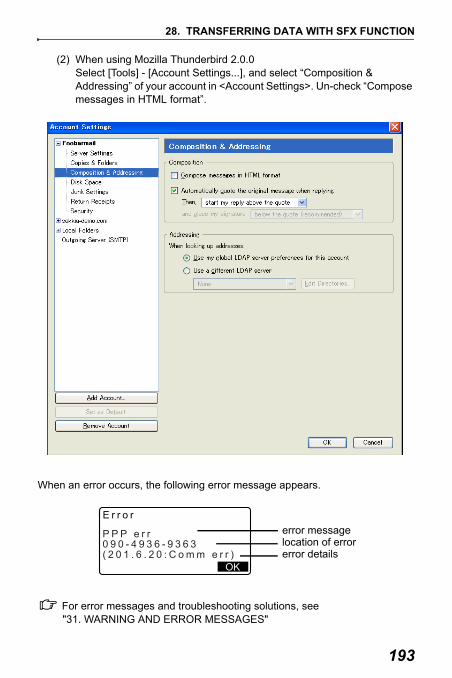
193
28. TRANSFERRING DATA WITH SFX FUNCTION
(2) When using Mozilla Thunderbird 2.0.0Select [Tools] - [Account Settings...], and select “Composition & Addressing” of your account in <Account Settings>. Un-check “Compose messages in HTML format”.
When an error occurs, the following error message appears.
For error messages and troubleshooting solutions, see "31. WARNING AND ERROR MESSAGES"
E r r o r
P P P e r r0 9 0 - 4 9 3 6 - 9 3 6 3( 2 0 1 . 6 . 2 0 : C o m m e r r )
OK
error messagelocation of errorerror details

194
29.USING EXTERNAL MEMORY MEDIAIt is possible to read in/output data from/to a USB memory device or SD card.
: • Do not remove the USB memory device or SD card during data read/write.
Doing so will cause data stored in the external memory media or the SET to be lost.
• Do not remove the battery or turn off the power during data read/write. Doing so will cause data stored in external memory media or the SET to be lost.
PROCEDURE
1. Slide the catch on the external interface hatch cover down to open.
2. Insert the USB memory device/SD card in the respective slot.
: An SD card should be inserted
with the contacts facing towards the instrument.
29.1 Inserting the USB Memory Device/SD Card

195
29. USING EXTERNAL MEMORY MEDIA
3. Close the cover.
• Push an inserted SD card further into the slot and release to eject.
PROCEDURE
1. Press {ON}.
2. Press {ESC} to display the Status screen.
3. Press [MEDIA] to display Media mode.
4. Select “Media selection”.
5. Select desired media type from "SD" or "USB".
6. Press {OK}.
29.2 Selecting Media Type
Media SDMedia selectionSave dataLoad known Pt.File statusQuick format
Media selectionType:SD

29. USING EXTERNAL MEMORY MEDIA
196
The measurement data (distance, angle, coordinate), known point data input on the SET, station point data and note stored in a JOB of the SET can be saved to the SD card/USB memory device. Also, if multiple JOBs are selected, they can be saved to one file.
• Data is saved in the external memory media with extension name .SDR and .CRD.
PROCEDURE
1. Select "Save data" in Media mode.
2. In the list of JOBs, select the JOB to be recorded and press { }. "Out" is displayed to the right of the selected JOB. Multiple JOBs can be selected.
3. After selecting the JOB(s), press [OK].
4. Enter the file name. Press { } to set the data.
5. Press [OK] to save the JOB to the external memory media. After saving a JOB, the screen returns to the JOB list.
If {ESC} is pressed while data is being recorded, data recording is canceled.
29.3 Storing JOB Data to External Memory Media
Media SDMedia selectionSave dataLoad known Pt.File statusQuick format
Format:SDR33Time
JOB01. SDRDate : Apr/01/2009
: 08:00
123.4MB / 3.8GB
Remaining memory / Total memory size

197
29. USING EXTERNAL MEMORY MEDIA
• Maximum size of file name: 8 characters (alphanumeric) excluding the file extension.
• Characters used to make File name: Alphabet (capital letters only), special characters (-)
• When a file is overwritten, the overwritten file is deleted.
By selecting "Load known Pt.", known point data stored in the external memory media can be read in the current JOB on the SET.
• Only coordinate records in files with the .SDR or .CRD extension name can be read on the SET.
PROCEDURE
1. Select "Load known Pt." in Memory mode.
2. Check the displayed current JOB name, then press [OK]
3. In the list of files, select the file to be read in and press { }.
4. Press [YES] to read in the file on the SET. <Media> is restored.
To cancel reading, press {ESC}.
29.4 Reading Known Point Data
Media SDMedia selectionSave dataLoad known Pt.File statusQuick format
OK
Load known Pt.
Job.JOB1
ABCDEFGHIJKLMNOPQZZZ
SDR
SDRSDR
SDR
YESNO
ABCDE5354byte
Format :SDR33Confirm ?
SDR
Jan/01/2009 17:02

29. USING EXTERNAL MEMORY MEDIA
198
By selecting "File status", file information can be displayed, file names can be edited and files can be deleted.
• When deleting all files together, format the external memory media."29.6 Formatting the Selected External Memory Media"
PROCEDURE Displaying File Information
1. Select "File status" in Media mode.
2. Press [OK].
3. In the list of the files stored in the external memory media, select a file to be displayed and press { }. Details of the file are displayed.
4. Press {ESC} to return to the file list.
29.5 Displaying and Editing Files
Media SDMedia selectionSave dataLoad known Pt.File statusQuick format
Load known Pt.JOB.Job1
ABCDEFGHIJKLMNOPQZZZ
SDR
SDRSDR
SDR
EDITDEL
ABCDE5354byte
Format :SDR33123.4MB / 3.8GB
SDR
Jan/01/2009 17:02
Remaining memory / Total memory size

199
29. USING EXTERNAL MEMORY MEDIA
PROCEDURE Editing the File Name
1. Follow steps 1 to 3 in “PROCEDURE Displaying File Information” until the screen shown at right is displayed.
2. Press [EDIT] and enter a new file name. Press { } to enter the new file name. The edited file name is displayed on the screen.
PROCEDURE Deleting a File
1. Follow steps 1 to 3 in “PROCEDURE Editing the File Name” until the screen shown at right is displayed.
2. Press [DEL]. Press [YES]. The file is deleted and the screen returns to the file list.
By selecting "Quick format", the SD card/USB memory device can be formatted.All files on the SD card/USB memory device are deleted, including files with extension names other than .SDR and .CRD.
PROCEDURE
1. Select "Quick format" in Media mode.
29.6 Formatting the Selected External Memory Media
EDITDEL
ABCDE5354byte
Format :SDR33123.4MB / 3.8GB
SDR
Jan/01/2009 17:02
O KDEL
ABCDE5354byte
Format :SDR33123.4MB / 3.8GB
.SDR
Jan/01/2003 17:02
EDITDEL
ABCDE5354byte
Format :SDR33123.4MB / 3.8GB
SDR
Jan/01/2009 17:02
Media SDMedia selectionSave dataLoad known Pt.File statusQuick format

29. USING EXTERNAL MEMORY MEDIA
200
2. Press [YES] to format. When formatting is completed, <Media> is restored.
YESNO
Format media
Confirm ?
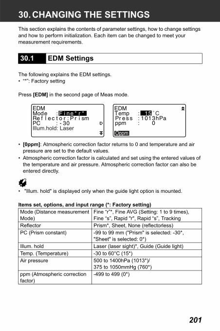
201
30.CHANGING THE SETTINGSThis section explains the contents of parameter settings, how to change settings and how to perform initialization. Each item can be changed to meet your measurement requirements.
The following explains the EDM settings.• “*”: Factory setting
Press [EDM] in the second page of Meas mode.
• [0ppm]: Atmospheric correction factor returns to 0 and temperature and air pressure are set to the default values.
• Atmospheric correction factor is calculated and set using the entered values of the temperature and air pressure. Atmospheric correction factor can also be entered directly.
• "Illum. hold" is displayed only when the guide light option is mounted.
Items set, options, and input range (*: Factory setting)
30.1 EDM Settings
Mode (Distance measurement Mode)
Fine “r”*, Fine AVG (Setting: 1 to 9 times),Fine “s”, Rapid "r", Rapid “s”, Tracking
Reflector Prism*, Sheet, None (reflectorless)PC (Prism constant) -99 to 99 mm ("Prism" is selected: -30*,
"Sheet" is selected: 0*)Illum. hold Laser (laser sight)*, Guide (Guide light)Temp. (Temperature) -30 to 60°C (15*) Air pressure 500 to 1400hPa (1013*)/
375 to 1050mmHg (760*)ppm (Atmospheric correction factor)
-499 to 499 (0*)
Illum.hold: Laser

30. CHANGING THE SETTINGS
202
• The screen will be displayed only when "Illum. hold " is set to "Guide" and the cursor is on "Guide".
Item set and option (*: Factory setting)
Atmospheric correction factorThe SET measures the distance with a beam of light, but the velocity of this light varies according to the index of refraction of light in the atmosphere. This index of refraction varies according to the temperature and air pressure.
• To precisely determine the atmospheric correction factor, the average temperature and air pressure along the measurement beam route must be taken. Take care when calculating the correction factor in mountainous terrain as the difference in height will result in differences in atmospheric conditions between two points.
• The SET is designed so that the correction factor is 0 ppm at an air pressure of 1013 hPa, a temperature of 15°C and a humidity of 0%.
• By inputting the temperature and air pressure values, the atmospheric correction value is calculated using the following formula and set into the memory.
• If the weather correction is not required, set the ppm value to 0.• The atmospheric correction factor can also be calculated in order to take
humidity into account."38.2 Atmospheric Correction for High Precision Distance Measurement"
The Guide light (Brightness level of the guide light)
1 to 3 (3*)
ppm = 282.59 -0.2942 x air pressure (hPa)
1 + 0.003661 x air temperature (°C)
Illum.hold: GuideGuide light: 3

203
30. CHANGING THE SETTINGS
Prism constant correctionReflective prisms each have their prism constant.Set the prism constant correction value of the reflective prism you are using. When selecting "None (Reflectorless)" in "Reflector", prism constant correction value is set to "0" automatically.
• The following are samples of the prism constant correction values of SOKKIA reflective prisms.
The following explains the Config Mode.
Observation Condition
Select “Obs. condition” in Config mode
Items set and options (*: Factory setting)
30.2 Configuration -Config Mode-
Dist mode Sdist*, Hdist, VdistTilt crn (Tilt angle compensation)
Yes(H,V)*, Yes(V), No
coll. crn (Collimation correction)
Yes*, No
AP01AR (Constant = 40mm)
Correction Value = -40
R
ConfigObs.conditionInstr.config
Comms setupUnit
Instr.const
Change Password
K=0.20
)
::
::
:Sea level crn NoStn.ID Incr. : 100
1

30. CHANGING THE SETTINGS
204
Automatic tilt angle compensation mechanismThe vertical and horizontal angles are automatically compensated for small tilt errors using the 2-axis tilt sensor.
• Read the automatically compensated angles when the display has stabilized.
• The horizontal angle error (vertical axis error) fluctuates according to the vertical axis, so when the instrument is not completely leveled, changing the vertical angle by rotating the telescope will cause the displayed horizontal angle value to change. Compensated horizontal angle = Measured horizontal angle + Tilt in angle /tan (Vertical angle)
• When the telescope is directed close to the zenith or nadir angle, tilt compensation is not applied to the horizontal angle.
Collimation correction The SET has a collimation correction function that automatically corrects horizontal angle errors caused by horizontal axis and leveling axis errors.
Sea level correctionThe SET calculates horizontal distance using slope distance values. As this horizontal distance does not take height above sea level into consideration, performing spherical correction is recommended when measuring at high altitudes. Spherical distance is calculated as follows.
C&R crn. (Earth curvature and refraction correction)
No, K=0.142, K=0.20*
V manual Yes, No*V.obs (Vertical angle display method)
Zenith*, Horiz, Horiz 90° (Horizontal ±90°)
Coord. N-E-Z*, E-N-ZAng.reso.(Angle resolution) SET250RX/350RX/550RX:1”*, 5”
SET650RX:1”, 5”*Sea level crn (Sea level correction)
Yes, No*
Stn.ID Incr. (station ID incre-ment)
0 to 99999 (100*)

205
30. CHANGING THE SETTINGS
Where: R = radius of the spheroid (6372000.000m)Ha = averaged elevation of the instrument point and target pointd1 = horizontal distance
V obs. (vertical angle display method)
Instrument ConfigurationSelect “Instr. Config” in Config mode
• "Guide pattern" is displayed only when the guide light option is selected.Items set and options (*: Factory setting)Power off 5min, 10min, 15min, 30min*, NoReticle lev 0 to 5 level (3*)Contrast 0 to 15 level (10*)Resume On, Off*EDM ALC Hold, Free*Guide pattern 1 (the red and green lights flash
simultaneously)*/2 (the red and green lights flash alternately)
R Ha–R
------------------ d1×=
Zenith Horiz Horiz 90°
10
FreeGuide pattern : 1
Spherical distance

30. CHANGING THE SETTINGS
206
Power-saving automatic cut-offTo save power, power to the SET is automatically cut off if it is not operated for the selected time.
Resume functionWhen the Resume function is set to “On” and the power is switched off and then on again, the screen appearing before the instrument was switched off, or a prior screen is redisplayed.
EDM ALCSet the light receiving status of the EDM. While carrying out continuous measurement, set this item according to the measurement conditions.
• When EDM ALC is set to "Free" the instrument’s ALC will be automatically adjusted if an error occurs as a result of the amount of light received. Set to "Free" when the target is moved during measurement or different targets are used.
• When "Hold" is set, the amount of light received will not be adjusted until initial adjustment has been performed and continuous measurement completed.
• Try setting to "Hold" when the light beam used for measurement is stable but is frequently obstructed by obstacles such as people, cars, or tree branches etc. preventing measurement from being performed.
• The EDM ALC setting will automatically be switched to "Free" when the distance measurement mode is set to "Tracking" (target is moved during distance measurement).
Communication Setup
Select “Comms setup” in Config mode
dWireless No
9600

207
30. CHANGING THE SETTINGS
Items set and options (*: Factory setting)
Output format and command operations: “Interfacing with the SOKKIA SDR Electronic Field Book” and “Command Operations” manuals.
SFX Communication using Bluetooth technologyData can also be transferred using Bluetooth technology when a cellular phone equipped with Bluetooth wireless technology is registered as a companion device. ( ""10. CONNECTING TO EXTERNAL DEVICES" PROCEDURE Registering Bluetooth companion devices")
Press [MODEM] in the screen at right.
Use { }/{ } to select the cellular phone registered in the Link device list and press { }.
• To perform SFX communication using Bluetooth technology, "Wireless" in "Comms setup" must be set to "Yes".
• When "Wireless" is set to "No", the [MODEM] softkey will not be displayed in <Dial-up>. "Port" will be automatically set to COM PORT and cannnot be changed.
Wireless Yes, No*Baud rate 1200bps, 2400bps, 4800bps, 9600bps*,
19200bps, 38400bpsData bits 8bit*, 7bitParity Not set*, Odd, EvenStop bit 1bit*, 2bitCheck sum Yes, No*Xon/Xoff Yes*, No
D i a l - u pS e n d m a i lR e c e i v e m a i lF T P c o n n e c t
ADR FTP A P MODEM
: F 9 0 0 i TP O R T c o n f i gP o r t
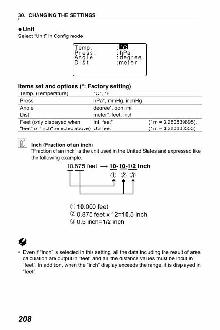
30. CHANGING THE SETTINGS
208
UnitSelect “Unit” in Config mode
Items set and options (*: Factory setting)
Inch (Fraction of an inch)“Fraction of an inch” is the unit used in the United States and expressed like the following example.
• Even if “inch” is selected in this setting, all the data including the result of area calculation are output in “feet” and all the distance values must be input in “feet”. In addition, when the “inch” display exceeds the range, it is displayed in “feet”.
Temp. (Temperature) °C*, °FPress hPa*, mmHg, inchHgAngle degree*, gon, milDist meter*, feet, inchFeet (only displayed when "feet" or "inch" selected above)
Int. feet* US feet
(1m = 3.280839895),(1m = 3.280833333)

209
30. CHANGING THE SETTINGS
International feet and US survey feetThe SET can display feet values in International feet and US survey feet units.International feet, the standard feet units, are referred to simply as “feet” elsewhere in this manual.US survey feet are units used in surveys by the U.S. Coast and Geodetic Survey and are referred to as “US feet” in this manual.When “feet” or “inch” is selected in “Dist”, the “Feet” item will appear on the screen as below. When “meter” is selected, this item will not be displayed.
Results displayed in feet will differ according to the unit selected in this item.
It is possible to allocate the softkeys in Meas mode to suit the measurement conditions. It is possible to operate the SET efficiently because unique softkey allocations can be preset to suit various applications and the ways that different operators handle the instrument.
• The current softkey allocations are retained until they are revised again, even when the power is cut off.
• It is possible to register two sets of key function allocations: user setting 1 and user setting 2.
• It is possible to recall the softkey arrays registered for User 1 and User 2 as necessary.
• When softkey allocations are recorded and registered, the previously recorded key settings are cleared. When a softkey array is recalled, the key array is changed to the key array that has been recalled, clearing the previous key array. Be sure to remember this.
30.3 Allocating Key Functions
F e e t I n t . f e e tf e e t

30. CHANGING THE SETTINGS
210
The following are the softkey allocations when the SET was shipped.
Page 1 [DIST] [ SHV] [0SET] [COORD]Page 2 [MENU] [TILT] [H.ANG] [EDM]Page 3 [MLM] [OFFSET] [REC] [S-O]
The following functions can be allocated to the softkeys.[DIST] : Distance measurement[ SHV] : Switch between angle display and distance display[0SET] : Set horizontal angle to 0[COORD] : Coordinates measurement[REP] : Repetition measurement[MLM] : Missing line measurement[S-O] : Setting-out measurement[OFFSET] : Offset measurement[REC] : To Record menu[EDM] : Setting EDM[H.ANG] : Set required horizontal angle[TILT] : Display tilt angle[MENU] : To Menu mode (Coordinates measurement, setting-out
measurement, offset measurement, repetition measurement, missing line measurement, REM measurement, resection measurement, surface area measurement, set-out line, set-out arc, point projection, intersections, traverse)
[REM] : REM measurement[RESEC] : Recection measurement[R/L] : Select horizontal angle right/left[ZA / %] : Switch between zenith angle/slope in %[HOLD] : Hold horizontal angle/release horizontal angle[RCL] : Display final measurement data[D_OUT] : Output measurement results to an external instrument[AIM] : Return signal[AREA] : Surface area measurement[F/M] : Switch between meters/feet[HT] : Set the instrument station height and target height[S-O LINE] : Setting-out line measurement[S-O ARC] : Setting-out arc measurement[P-PROJ] : Point projection measurement[INTSCT] : Intersections measurement[TRAVER] : Traverse adjustment[L-PLUM] : Brightness configuration for laser plummet[---] : No functions set

211
30. CHANGING THE SETTINGS
Softkey Allocation ExamplesIt is possible to allocate the same key to each page (example 1). The same function can be allocated to more than one key on the same page (example 2). And it is also possible to allocate a function to only one key (example 3). Allocation example 1:P1 [DIST] [ SHV] [H.ANG] [EDM]P2 [DIST] [ SHV] [H.ANG] [EDM]Allocation example 2:P1 [DIST] [DIST] [ SHV] [ SHV]
Allocation example 3:P1 [DIST] [ SHV] [– – –] [– – –]
PROCEDURE Allocating functions
1. Select “Key function” in Config Mode. Select “Define.” Currently allocated softkeys are displayed in <Key function>.
2. Align the cursor with the softkeys whose allocation you want to change using { }/{ }. The cursor of the selected softkey flashes.
3. Change the softkey function using { }/{ }.Set the softkey function and its location by pressing { }/{ }. The set softkey stops flashing and the cursor flashes on the next softkey.
4. Repeat steps 2 to 3 only as many times as necessary.
5. Press [OK] to record the
allocations and restore <Key function>.The functions with their new allocations are displayed in Meas mode.
TILT

30. CHANGING THE SETTINGS
212
PROCEDURE Registering an allocation
1. Allocate functions to the softkeys."PROCEDURE Allocating functions"
2. Select “Key function” in Config mode.
3. Select “Registration.”Select either “User 1” or “User 2” as the softkey array to be registered.
4. Press { }. The softkey array is registered as user 1 or user 2 and <Key function> is restored.
PROCEDURE Recalling an allocation
1. Select “Key function” in Config Mode.
2. Select “Recall.” Select the key array for either User 1, User 2, or Default (setting when the SET was shipped), and press { }.<Key function> is restored. This displays the functions in the recalled array in Meas mode.

213
30. CHANGING THE SETTINGS
Set password can be changed.
• No password was set when the SET was shipped.
PROCEDURE Changing password
1. Select "Change Password" in Config mode.
2. Input old password and press { }.
3. Input new password twice and press { }. The password is changed and <Config> is restored.
• If no password was input as new password and { } was pressed, no password is set.
• Input range of password: 3 or more characters and 8 or fewer characters
30.4 Changing Password
Change passwordOld password
Change passwordNew password
New password again

30. CHANGING THE SETTINGS
214
The following explains the two methods of restoring default settings: Restoring set items to initial settings and turning power on. Initializing the data and turning power on.
• Restore the following items to the initial settings when the SET was shipped.EDM setting, Config mode settings (including softkey arrays)
About initial settings when the SET was shipped: "30.1 EDM Settings", "30.3 Allocating Key Functions"
• Initialize the data. The following data is initialized.Data within all jobsKnown point data within memoryCode data within memoryDial-up menu password
PROCEDURE Restoring set items to initial settings and turning power on
1. Turn the power off.
2. While pressing {F4} and {BS}, press {ON}.
3. The SET is turned on, “Default set” appears on the screen and all items are restored to their initial settings.
PROCEDURE Initializing the data and turning the power on
1. Turn the power off.
2. While pressing {F1}, {F3} and {BS}, press {ON}.
3. The SET is turned on, “Clearing memory...” appears on the screen and all items are restored to their initial settings.
30.5 Restoring Default Settings

215
31.WARNING AND ERROR MESSAGESThe following is a list of the error messages displayed by the SET and the meaning of each message. If the same error message is repeated or if any message not shown below appears, the instrument has malfunctioned. Contact your local dealer.
Attached file errThe file extension of the selected file is not ".sdr".
BadConditionThe air is shimmering a lot, etc., measuring conditions are poor.
The center of the target cannot be sighted.Resight the target.
Unsuitable distance measurement conditions when reflectorless measurement is set. When reflectorless measurement is set, distance cannot be measured because the laser beam is striking at least two surfaces at the same time.Choose a single surface target for distance measurement.
Bad file nameFile name is not entered when saving data on external media.
Calculation errorCoordinates identical to the known point coordinates observed during resection exist. Set another known point so that the known point coordinates do not coincide.
Can’t move dirAn error occurred while trying to move a directory on the FTP server.
Cannot format Read-only file existExternal media contains read-only file. External media cannot be formatted.
Checksum errorA sending/repetition error has occured between the SET and external equipment.Send/receive the data again.
Clock errorClock error occurs when the voltage of the lithium battery decreases or the battery itself is depleted. For details on replacing lithium batteries contact your local dealer.

31. WARNING AND ERROR MESSAGES
216
Communication errorComm err
A reception error has occurred in coordinate data from an external instrument.Check the settings of parameters concerning communication conditions.
"30.2 Configuration -Config Mode-"
Delete mail errAn error occurred while trying to delete received e-mail.
Encode errCorrect encoding (HEXBIN) is not used. Check that HEXBIN is set in the encoding settings for the e-mail software being used.
FileName FullThis file name cannot be used again. File names made up of said file name plus all possible single-letter suffixes "a" to "z" already exist on the server.
File not existThis file does not exist in the current directory.
Flash write error!Flash mount error!FlashMem err
It is impossible to read in data.Contact your local dealer.
FTPfile open errAn error occurred while trying to open a file on the FTP server.
FTP receive errAn error occurred while reading in a file from the FTP server.
FTP send errAn error occurred while writing a file to the FTP server.
FTPsvr con errorAn error occurred while connecting to the FTP server. Check the FTP server settings.
FTPsvr search errAn error occurred while obtaining a file list from the FTP server.

217
31. WARNING AND ERROR MESSAGES
Incorrect PasswordInput password does not match set password. Input correct password.
Insert mediaExternal media is not inserted.
Invalid mediaIncorrect external media is inserted.
Invalid baselineDuring setting-out line measurement or point projection measurement, baseline has not been defined correctly.
Job data errCannot read/write JOB data. Either the JOB name is invalid or an internal error occurred.
Job record fullNo more records can be recorded in the current JOB. Record in a different JOB.
Line not terminatedA JOB data format error has occurred.
Mail not existThere is no e-mail for the SET. Check that the e-mail sent included a correct subject line.
Mail search errThe mail list could not be obtained due to an error during reception. Try again.
Media errorAn error has occurred in loading or saving data to external media.
Media full !There is no more room to enter data on external media.
Media not foundExternal media was removed during Media mode operation.
Memory is fullThere is no more room to enter data.Record the data again after deleting unnecessary data from the JOB or coordinate data from the memory.

31. WARNING AND ERROR MESSAGES
218
Need 1st obsDuring missing line measurement, the observation of the starting position was not completed normally.Sight the starting position accurately and press [OBS] to perform the measurement again.
Need 2nd obsDuring missing line measurement, the observation of the target was not completed normally.Sight the target accurately and press [MLM] to perform the measurement again.
Need offset pt. Observation of the offset point during offset measurement was not completed normally.Sight the offset point accurately and press [OBS] to perform the measurement again.
Need prism obsDuring REM measurement, the observation of the target was not completed normally.Sight the target accurately and press [OBS] to perform measurement again.
New password Diff.Passwords input when setting a new password do not match.Input the same password twice.
No attached fileThere is no file attached to the selected e-mail.
No dataWhen searching for or reading in coordinate data or searching for code data, the search stopped either because the item in question does not exist or the data volume is large.
No fileThere is no file for loading known point data or displaying data on the currently selected external media.
No solutionThe calculation of the instrument station coordinates during resection does not converge. Assess the results and if necessary, perform the observation again.

219
31. WARNING AND ERROR MESSAGES
Intersect point could not be calculated. Either necessary data items were not input or the Intersect point does not exist.
North/East is null, Read errorThe Northing or Easting field of the given coordinate is null.Input the coordinate.
Out of range The tilt of the instrument exceeds the tilt angle compensation range during measurement.Level the instrument again.
"7.2 Levelling"
Out of valueDuring gradient % display, the display range (less than ±1000%) has been exceeded.During REM measurement, either the vertical angle has exceeded horizontal ±89° or the measured distance is greater than 9999.999m.Install the instrument station far from the target.
The instrument station coordinates calculated during resection are too high.Perform the observation again.
During setting-out line measurement, scale factor has been less than 0.100000 or exceeded 9.999999.
During area calculation, results exceeded the display range.
Over filesFiles cannot be added to the external media because they exceed the file number limit.
POPsvr con errorConnection to the POP server failed. Check the POP server settings.
PPP errAn error occurred during dial-up connection. Check that the phone and cable are connected correctly and that the correct login name and password have been entered.

31. WARNING AND ERROR MESSAGES
220
Print or send firstJOB data output (transmission to the host computer or output to the printer) is not completed before JOB is cleared.Either transmit the JOB to be cleared to the host computer or output it to the printer.
Pt already on routeTraverse tried to close on a traverse point other than the Start pt. during automatic route search. Press any key to return to the last point found in automatic route search. Either select the next traverse point to continue the current search or specify the Start pt. to close a closed-loop traverse.
RAM cleared(Displayed when the SET is switched on) The resume function does not work because more than one week (memory back-up period) has passed since the SET was last switched off. After more than one week, even though “Resume” is still set to “On,” the resume function has been canceled.
Rcv mail errAn error occurred while e-mail was being received.
Read-only fileRead-only file on the external media cannot be changed and file contents cannot be edited or deleted.
Same coordinatesThe same values are input in Pt.1 and Pt.2 in setting-out line measurement. SET cannot define the baseline.
SDR format errThe file read in is not SDR format. Check the file.
Send mail errAn error occurred while e-mail was being sent.
Signal offMeasuring conditions are poor, and there is not any reflective light for measuring distances.Resight the target. When using reflective prisms, effectiveness will be improved by increasing the number of prisms used.
SMTPsvr con errorAn error occurred while connecting to the SMTP server. Check the SMTP server settings.

221
31. WARNING AND ERROR MESSAGES
Station coord is NullCannot calculate. Station point coordinate is set to “Null”.Input the coordinate.
Temp Range OUTSET is outside useable temperature range and accurate measurement cannot be performed. Repeat measurement within the appropriate temperature range. If the SET is used under direct sunlight, use an umbrella to protect it against the heat of the sun.
Time out (during measurement)Measuring conditions are poor, and due to the insufficient amount of reflective light, measuring could not be carried out within the time specified.Resight the target. When using reflective prisms, effectiveness will be improved by increasing the number of prisms used.
Time out (during SFX dial-up communication)Operation was not completed within the time specified so was forcibly terminated.
Too shortInput password has fewer than 3 characters. Password must have 3 or more characters and 8 or fewer characters.
The calculated result is too large to be displayed on the screen in its totality.
If the printer cable is attached during measurement, measurement cannot be carried out correctly. SET notifies you by displaying the screen above and beeping. When the cable is removed, the previous screen is restored.If connected SDR or host computer is turned Off, the above screen appears. This is normal, and does not indicate trouble. If connected SDR or host computer is turned On again or cable is connected again, the previous screen is restored.

222
32.CHECKS AND ADJUSTMENTSA SET is a precision instrument that requires fine adjustments. It must be inspected and adjusted before use so that it always performs accurate measurements.• Always perform checking and adjustment in the proper sequence beginning
from "32.1 Plate Level" to "32.8 Guide Light".• In addition, the instrument should be inspected with special care after it has
been stored a long time, transported, or when it may have been damaged by a strong shock.
• Make sure the instrument is securely set up and stable before performing checks and adjustments.
The bubble tube is made of glass, so it is sensitive to temperature changes or to shock. Check and adjust it as outlined below.
PROCEDURE Checking and adjusting
1. Level the instrument and check the position of the bubble of the plate level.
"7.2 Levelling" steps 3 to 5
2. Turn the upper part through 180° and check the bubble position.If the bubble is still centered, no adjustment is necessary.If the bubble is off-center, adjust as follows.
3. Correct half of the bubble displacement using levelling foot screw C.
32.1 Plate Level

223
32. CHECKS AND ADJUSTMENTS
4. Correct the remaining half of the displacement by using the adjustment pin to rotate the plate level adjustment screw. When the plate level adjustment screw is turned in the counterclockwise direction, the bubble moves in the same direction.
5. Rotate the top of the instrument and continue adjustments until the bubble remains centered for any position of the upper part.If the bubble does not move to the center even when the adjustment has been repeated, ask your local dealer to adjust it.
PROCEDURE Checking and adjusting
1. Perform the plate level inspection and adjustment or carefully use the plate level to level the instrument.
"7.2 Levelling" steps 1 to 2
2. Check the position of the bubble of the circular level.If the bubble is not off-center, no adjustment is necessary.If the bubble is off-center, perform the following adjustment.
32.2 Circular Level

32. CHECKS AND ADJUSTMENTS
224
3. First confirm the off-center direction.Use the adjusting pin to loosen the circular level adjustment screw on the side opposite to the direction the bubble is displaced to move the bubble to the center.
4. Adjust the adjusting screws until the tightening tension of the three screws is the same to align the bubble in the middle of the circle.
• Be careful that the tightening tension is identical for all the adjusting screws.• Also, do not over-tighten the adjusting screws as this may damage the circular
level.
If the tilt angle shown on the display shifts from tilt angle 0° (zero point), the instrument is not correctly levelled. This will adversely affect angle measurement. Perform the following procedure to cancel the tilt zero point error.
PROCEDURE Check
1. Carefully level the instrument. If necessary, repeat the procedures to check and adjust the bubble levels.
2. Set the horizontal angle to 0°. Press [0SET] twice in the first page of the Meas mode screen to set the horizontal angle to 0°.
32.3 Tilt Sensor

225
32. CHECKS AND ADJUSTMENTS
3. Select “Instr. const” in the Config. mode screen to display the current correction constant in the X (sighting) direction and Y (horizontal axis) direction.
Select “Tilt X Y” and press { } to display the tilt angle in the X (sighting) direction and Y (horizontal axis) direction.
4. Wait a few seconds for the display to stabilize, then read the automatically compensated angles X1 and Y1.
5. Loosen the horizontal clamp and turn the instrument 180° while referring to the displayed horizontal angle, then retighten the clamp.
6. Wait a few seconds for the display
to stabilize, then read the automatically compensated angles X2 and Y2.
7. In this state, calculate the following offset values (tilt zero point error).Xoffset = (X1+X2)/2Yoffset = (Y1+Y2)/2
7-10
ConfigObs.conditionInstr.config
Comms setupUnit
Instr.const
8

32. CHECKS AND ADJUSTMENTS
226
If one of the offset values (Xoffset, Yoffset) exceeds ±20", adjust the value using the following procedure.When the offset value falls within the range ±20", adjustment is not necessary. Press {ESC} to return to <Instr. const>.
PROCEDURE Adjustment
8. Store values X2 and Y2.Press [OK]. “Take F2” is displayed.
9. Rotate the top of the instrument through 180° until the displayed horizontal angle is 180° ±1’ and [OK] is displayed.
10. Wait a few seconds for the display to stabilize, then store the automatically compensated angles X1 and Y1.Press [YES] to store tilt angles X1 and Y1. The new correction constant is displayed.
11. Confirm that the values are in the adjustment range.If both correction constant are within the range ±180, select [YES] to renew the correction angle. <Instr. const> is restored. Continue to step 12.If the values exceed the adjustment range, select [NO] to cancel the adjustment and restore <Instr. const>. Contact your local dealer to perform the adjustment.
7-10 4 -11

227
32. CHECKS AND ADJUSTMENTS
PROCEDURE Recheck
12. Press { } at <Instr. const>.
13. Wait a few seconds for the display to stabilize, then read the automatically compensated angles X3 and Y3.
14. Rotate the top of the instrument through 180°.
15. Wait a few seconds for the display to stabilize, then read the automatically compensated angles X4 and Y4.
16. In this state, the following offset values (tilt zero point error) are calculated.Xoffset = (X3+X4)/2Yoffset = (Y3+Y4)/2When both offset values fall within the range ±20", adjustment is completed. Press {ESC} to return to <Instr. const>.
If one of the offset values (Xoffset, Yoffset) exceeds ±20", repeat the check and adjustment procedures from the beginning. If the difference continues to exceed ±20" after repeating the check 2 or 3 times, have your local dealer perform the adjustment.

32. CHECKS AND ADJUSTMENTS
228
With this option you can measure collimation error in your instrument so that the SET can correct subsequent single face observations. To measure the error, make angular observations using both faces.
Procedure
1. Display <Collimation>.Select “Instr.const” in the Config. mode screen and select “Collimation”.
2. Sight the reference point in Face 1. Sight the reference point in Face 1 and press [OK].
3. Sight the reference point in Face 2.Rotate the instrument 180°. Sight the same point in Face 2 and press [OK].
4. Set the constant.Press [YES] to set the constant.
• Press [NO] to discard the data and return to <Collimation>.
32.4 Collimation

229
32. CHECKS AND ADJUSTMENTS
PROCEDURE Check 1: Perpendicularity of the reticle to the horizontal axis
1. Carefully level the instrument.
2. Align a clearly visible target (the edge of a roof for example) on point A of the reticle line.
3. Use the telescope fine motion screw to align the target to point B on a vertical line.If the target moves parallel to the vertical line, adjustment is unnecessary. If its movement deviates from the vertical line, have our service representative adjust it.
PROCEDURE Check 2: Vertical and horizontal reticle line positions
• Perform the check procedure under slightly hazy and weakly scintillating conditions.
1. Install a target at a point about 100m in the horizontal direction from the SET.
2. Level the instrument carefully, turn on the instrument's power.
32.5 Reticle

32. CHECKS AND ADJUSTMENTS
230
3. While the Meas mode screen is displayed and the telescope is in face left, sight the center of the target and read out the horizontal angle A1 and the vertical angle B1.Example:Horizontal angle A1=18° 34' 00"
Vertical angle B1=90° 30' 20"
4. While the telescope is in face right, sight the center of the target and read out the horizontal angle A2 and the vertical angle B2.Example:Horizontal angle A2=198° 34' 20" Vertical angle B2=269° 30' 00"
5. Do the calculations: A2-A1 and B2+B1If A2-A1 is within 180°±20″and B2(B1 is within 360°±40″, adjustment is unnecessary.Example:A2-A1 (Horizontal angle)
=198° 34' 20"- 18° 34' 00"=180° 00' 20"B2-B1 (Vertical angle)=269° 30' 00" + 90° 30' 20"=360° 00' 20"
If the difference is large even after repeating the check 2 or 3 times, have our service representative perform the adjustment.

231
32. CHECKS AND ADJUSTMENTS
PROCEDURE Check
1. Carefully level the SET and exactly center a survey point in the reticle of the optical plummet.
2. Turn the upper part 180° and check the position of the survey point in the reticle.If the surveying point is still centered, no adjustment is necessary.If the surveying point is not still centered in the optical plummet, adjust as follows:
PROCEDURE Adjustment
3. Correct half the deviation with the levelling foot screw.
4. Firmly hold down the top portion of the instrument, and remove the optical plummet knob cover, then remove the optical plummet reticle cover on the inside.Replace the optical plummet knob cover.Use the 4 adjusting screws of the optical plummet to adjust the remaining half of the deviation as show below.
32.6 Optical Plummet
Optical plummetreticle cover
Optical plummetknob cover

32. CHECKS AND ADJUSTMENTS
232
5. When the survey point is on the lower (upper) part of the illustration:1 Loosen the upper (lower)
screw slightly.2 Tighten the lower (upper)
screw by the same amount.
6. If the survey point is on the solid line (dotted line):3 Loosen the right (left) screw
slightly.4 Tighten the left (right) screw
by the same amount.
7. Check the adjustment by rotating the upper part of the instrument. The survey point should remain centered in the reticle. If necessary, repeat the adjustment.
8. Remove the optical plummet knob cover, and install the optical plummet reticle cover on the inside.Replace the optical plummet knob cover.
Do not over-tighten the 4 adjusting screws as this may cause the reticle to go out of adjustment.
1 (2)
2 (1)
4 (3)
3 (4)

233
32. CHECKS AND ADJUSTMENTS
The additive distance constant K of the SET is adjusted to 0 before delivery. Although it almost never deviates, use a baseline with a known distance precision to check that the additive distance constant K is close to 0 several times a year and whenever the values measured by the instrument begin to deviate by a consistent amount. Perform these checks as follows.
• Errors in setting up the instrument and reflective prism or in sighting the target will influence the additive distance constant. Be extremely careful to prevent such errors when performing these procedures.
• Set up so that the instrument height and the target height are identical. If a flat place is not available, use an automatic level to make sure the heights are identical.
PROCEDURE Check
1. Find an area of flat ground where two points 100m apart can be selected. Set up the Instrument at point A and the reflective prism at point B. Establish a point C half way between points A and B.
2. Precisely measure the horizontal distance between point A and point B 10 times and calculate the average value.
3. Place the SET at point C directly between points A and B and set up the reflective prism at point A.
4. Precisely measure the horizontal distances CA and CB 10 times each and calculate the average value for each distance.
32.7 Additive Distance Constant

32. CHECKS AND ADJUSTMENTS
234
5. Calculate the additive distance constant K as follows.K = AB - (CA+CB)
6. Repeat steps 1 to 5 two or three times. If the additive distance constant K is within ±3mm even once, adjustment is unnecessary. If it always exceeds this range, have our service representative perform an adjustment.
When the dividing line (the position where it switches back and forth from red to green) for the red and green guide lights is off centered from the reticle lines, use the following procedures to make adjustments.
• The guide light is an optional function. Set "Illum. Hold" to "Guide" in Config. mode, Use the setting page to select, check and adjust the guide light.
"30.1 EDM Settings" and "36. OPTIONAL ACCESSORIES"
PROCEDURE Checks
1. Install a prism at a point about 20 meters in the horizontal direction from the SET.
2. Level the instrument.
3. Sight the center of the prism with the telescope (face left).
4. Hold { } down to turn the guide lights on.
32.8 Guide Light

235
32. CHECKS AND ADJUSTMENTS
5. Set the horizontal angle to 0° by pressing [0SET] twice on the first page of the Meas mode.
6. Look through the telescope to verify that the guide lights are being reflected in the prism.
If both colors (red and green) are visible: proceed to procedure 7.If only the red or the green are visible: proceed to procedure 10.
7. Move the top of the instrument slightly while looking through the telescope, measure the horizontal angle of the position that changes only to green from both colors (red and green) of the guide light colors that are reflected in the prism.
8. Move the top of the instrument slightly while looking through the telescope, measure the horizontal angle of the position that changes only to red from both colors (red and green) of the guide light colors that are reflected in the prism.
9. Calculate the difference of the angle of the horizontal angle to search for the offset direction of the dividing line of the guide lights from the measurement values of procedures 7 and 8.
red green

32. CHECKS AND ADJUSTMENTS
236
Example: (Procedure 7) The horizontal angle 0°03' 30" = 04' 30" to the right from the reticle line (=0° set position) of the position that changes to green only from both colors (red and green) of the colors of the guide lights that are reflected in the prism.(Procedure 8) The horizontal angle 359°57' 00" = 03' 00" to the left from the reticle line (=0° set position) of the position that changes to green only from both colors (red and green) of the colors of the guide lights that are reflected in the prism.
The angle difference for procedures 7 and 8 is 1' 30," with this the dividing line for the green and the red shifts to the right side (the green side).
The illustration depicts how the left and right colors of the guide light are reflected in a prism and seen when viewed through the telescope.
When the angle difference is more than 1', proceed to the adjustments for procedure 10.
When the angle difference is less than 1', adjustments are unnecessary.
4’30"3’00"
00 00’00"00 04’30"359 57’00"
Range forboth colors
Green onlyrange
Red onlyrange

237
32. CHECKS AND ADJUSTMENTS
PROCEDURE Adjustments
10. Adjust the dividing line for the red and green lights of the guide lights that are reflected in the prism so that it is centered in the reticle.When only the red is visible, or if the dividing line shifts onto the red side: turn the guide light adjustment screw clockwise.When only the green is visible, or if the dividing line shifts onto the green side: turn the guide light adjustment screw counterclockwise.
11. Carry out a check of procedures 7 to 9 once again.When the measurement value difference for the horizontal angle is more than 1', then repeat the adjustments for procedure 10.When the measurement value difference for the horizontal angle is less than 1', then adjustments are complete.
Guide lightadjustment screw

32. CHECKS AND ADJUSTMENTS
238
Checks and adjustments are performed using an adjustment target (cut out and use targets printed at the back of this manual). As this target is made of paper great care must be taken to prevent it getting wet.
PROCEDURE Check
1. Level the instrument and emit the laser plummet beam.
"7.2 Levelling"
2. Rotate the upper part horizontally and place a target so that it is aligned with the center of the circle created by the rotating laser plummet beam.
• Laser beam remains centered on the center of the target – No adjustment necessary
• Laser beam strays from the center of the target – Adjustment necessary.
• Laser beam draws a circle outside the target circle – Contact your local dealer.
PROCEDURE Adjustment
1. Turn the laser plummet adjustment cap anticlockwise and remove.
32.9 Laser Plummet
5mm

239
32. CHECKS AND ADJUSTMENTS
2. Emit the laser plummet beam.
3. Note the current position (x) of the laser beam.
4. Turn the upper part of the instrument horizontally through 180° and note the new position (y) of the laser beam.Adjustment will bring the laser beam to a point midway along a line drawn between these two positions.
5. Check the position of the desired final position. Place a target so that its center is aligned with the desired final position.The remaining deviation will be adjusted using the 4 fine adjustment screws.
:• Be extremely careful to adjust all
the fine adjustment screws by the same amount so that none will be over-tightened.
• Turn screws clockwise to tighten.
6. When the laser beam is on the upper (lower) part of Fig. A the up/down adjustment is made as follows:
Insert the provided hexagon key wrench into both the upper and lower screws.
x yDesired final position
Target
Fine adjustment screws
Fig. A
Desired final position

32. CHECKS AND ADJUSTMENTS
240
Slightly loosen the upper (lower) screw and tighten the lower (upper) screw. Make sure that the tightening tension for both screws is identical. Continue to adjust until the laser beam is on the horizontal line of the target.
7. When the laser beam is in the right (left) part of Fig. B the left (right) adjustment is made as follows:
Insert a hexagon key wrench into both the left and right screws.Slightly loosen the right (left) screw and tighten the left (right) screw. Make sure that the tightening tension for both screws is identical.
Continue to adjust until the laser beam is aligned with the target center.
8. Turn the upper part of the instrument horizontally and check that the laser beam is now aligned with the target center.
9. Re-attach the laser plummet adjustment cap.
Fig. B

241
32. CHECKS AND ADJUSTMENTS
• Tightening each of the fine adjustment screws moves the laser plummet beam in the directions shown below.
Up
RightLeft
Down
Tighten "Up" screw
Tighten "Right" screw
Tighten "Down" screw
Tighten "Left"screw
Fine adjustment screws Laser plummet adjustment cappointing towards user

242
33.POWER SUPPLIES• Operate your SET with the following combinations of power equipment.
• Be sure to carefully read the operating manuals for the battery and charger before operating.
• Never use any combination other than those indicated below. If you do, the SET could be damaged.
*: Optional accessories for SET250RX and Low Temperature Models.
BDC46B CDC68 EDC113A/C (110 to 240 VAC)EDC113B (110 to 125 VAC)
Charger*External battery*
AC adapter* Power cable*
Cable*
For car cigarette lighter
AC adapter
Water-resistant case*
Output cable length: 0.8m
Output cable length: 3m
EDC136-compliant EDC2A (w/ label)
Battery Charger Cable for charger
EDC137A/C(110 to 240V AC)EDC137B(110 to 125V AC)
EDC113A/C (110 to 240V AC)EDC113B (110 to 125V AC)

243
33. POWER SUPPLIES
External power supply equipment• When using EDC2A mount the BDC46B in place to maintain the balance of the
instrument.• Make sure that the car cigarette lighter is 12 V DC and that its negative terminal
is grounded. Use it with the car engine running.

244
34.TARGET SYSTEM• Because all SOKKIA reflecting prisms and accessories have standardized
screws, it is possible to combine these prisms, accessories, etc. according to your objectives.
• The following are all special accessories (sold separately).• Because these targets (*2) are coated with fluorescent paint, they reflect when
there is little light.
• When using a reflecting prism equipped with a target for distance and angle measurements, be sure to direct the reflective prism correctly and sight the center of the prism target accurately.
• Each reflective prism (*1) has its own prism constant value. When changing prisms, be sure to change the prism constant correction value.
• To use the triple prism assembly AP31 or AP32 as a single prism for short distance measurements, mount the single reflective prism AP01AR in the center mounting hole of the prism holder.
series
AP01AR
APS12R-AR APS11R-AR
APS12R-MAR APS11R-MAR
Prism system tribrachs
Prism height adaptors
Prism holders
Prism
Targets
APS34R-MAR

245
34. TARGET SYSTEM
2-point target (2RT500-K)This target is used for two-distance offset measurement.
• For information about reflective sheet targets and target devices, contact your local dealer.
Instrument height adaptor (AP41)This device is used to adjust the height of the target.
• Adjust the level of the AP41 instrument height adaptor following the checking and adjustment methods of plate level.
"32.1 Plate Level"
• Adjust the optical plummet of the AP41 instrument height adaptor following the checking and adjustment methods of optical plummet.
"32.6 Optical Plummet"
• Make sure that the instrument height “236” (mm) is displayed in the instrument height adjustment window.
Adjusting plate (WASeries)Adjust the circular level of the adjusting plate for a prism following the checking and adjustment methods of circular level.
"32.2 Circular Level"
Heightadjustmentwindow
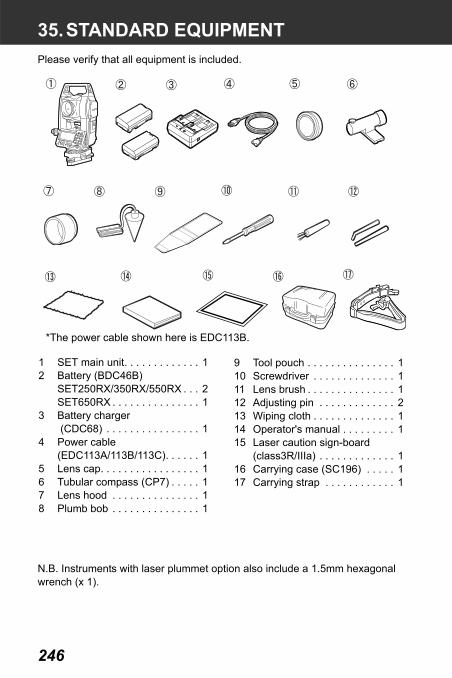
246
35.STANDARD EQUIPMENTPlease verify that all equipment is included.
N.B. Instruments with laser plummet option also include a 1.5mm hexagonal wrench (x 1).
*The power cable shown here is EDC113B.
1 SET main unit. . . . . . . . . . . . . 12 Battery (BDC46B)
SET250RX/350RX/550RX . . . 2SET650RX . . . . . . . . . . . . . . . 1
3 Battery charger (CDC68) . . . . . . . . . . . . . . . . 1
4 Power cable(EDC113A/113B/113C). . . . . . 1
5 Lens cap. . . . . . . . . . . . . . . . . 16 Tubular compass (CP7) . . . . . 17 Lens hood . . . . . . . . . . . . . . . 18 Plumb bob . . . . . . . . . . . . . . . 1
9 Tool pouch . . . . . . . . . . . . . . . 110 Screwdriver . . . . . . . . . . . . . . 111 Lens brush . . . . . . . . . . . . . . . 112 Adjusting pin . . . . . . . . . . . . . 213 Wiping cloth . . . . . . . . . . . . . . 114 Operator's manual . . . . . . . . . 115 Laser caution sign-board
(class3R/IIIa) . . . . . . . . . . . . . 116 Carrying case (SC196) . . . . . 117 Carrying strap . . . . . . . . . . . . 1

247
35. STANDARD EQUIPMENT
Tubular compass (CP7)Slide the tubular compass into the tubular compass slot, loosen the clamp screw, then rotate the top part of the instrument until the compass needle bisects the index lines. The telescope's face left sighting direction in this position will indicate magnetic north. After use, tighten the clamp and remove the compass from the slot.
The tubular compass is susceptible to the influence of nearby magnets or metal. Such influence could cause it to fail to accurately indicate magnetic north. Do not use magnetic north as indicated by this compass for base line surveying.
Plumb bobThe plumb bob can be used to set up and center the instrument on days when there is little wind. To use the plumb bob, unwind its cord, pass it through the cord grip piece as shown in the figure to adjust its length, then suspend it from the hook attached to the centering screw.
Handle The carrying handle can be removed from the instrument. To remove it, loosen the handle securing screw.
Tubularcompassslot
Handle Handlesecuringscrews

248
36.OPTIONAL ACCESSORIESThe following are optional accessories which are sold separately from the SET.
Target and power supply optional accessories: "33. POWER SUPPLIES" and "34. TARGET SYSTEM".
Wireless keyboard (SF14)For SET250RX/350RX/550RXSF14 makes measuring operation and inputting data easier and speedier. The SET is operated from the Wireless Keyboard by pointing the Wireless Keyboard beam at the Beam Detector on the SET and pressing the required operation keys.
Location of operation keys on the wireless keyboard: "4.1 Parts of the Instrument", operation: "SF14 Manual"
Telescope eyepiece lens (EL7)Magnification: 40XField of view: 1° 20'
Diagonal eyepiece (DE25) The diagonal eyepiece is convenient for observations near the nadir and in narrow spaces.Magnification: 30X
After removing the handle from the SET, loosen the attachment screw to remove the telescope eyepiece. Then screw the diagonal lens into place.
Handle removal method: "35. STANDARD EQUIPMENT"
Solar filter (OF3A)When sighting targets where glare is present, solar observations for example, attach it to the objective lens of the SET to protect its interior and the eyes of the operator. The filter part can be flipped up without being removed.
Remote operation
DE25

249
36. OPTIONAL ACCESSORIES
Battery Unit (BDC55)BDC55 is used as the power source for the ACE5 and LSE1.
Auto-collimation eyepiece(ACE5) The ACE5 is designed to detect a slight shift in inclimation of the reflector. The BDC55 is the power source for the ACE5. The buttons on the BDC55 can also be used to operate the ACE5. For details, see the ACE5 Operator’s manual.
Laser Sighting Eyepiece(LSE1) The LSE1 emits a visible laser beam along the telescope collimation axis. The BDC55 is the power source for the LSE1. For details, see the LSE1 Operator’s manual.
Printer cable (DOC46)The SET can be connected to a Centronics specification printer which supports ESC/PTM by the printer cable DOC46. This allows direct output of data from the SET to a printer.

36. OPTIONAL ACCESSORIES
250
Interface cableConnect between the SET and the host computer for data output.
Computer Cable NotesPC9800 Series
DOC25 Length: 2mPin Numbers and signal levels: RS-232C compatibleD-sub connector: 25 pins (female)
IBM PC/AT or compatible
DOC26 Length: 2mPin Numbers and signal levels: RS-232C compatible
DOC 27 D-sub connector: DOC26: 25 pins (female)DOC27: 9 pins (female)
Other computers
DOC1 No connector for attachment to a computer.

251
37.SPECIFICATIONSExcept where stated, the following specifications apply to all SETs.
TelescopeLength: 171mmAperture: 45mm (EDM:48mm)Magnification
SET250RX/350RX/550RX: 30XSET650RX: 26X
Image: ErectResolving power:
SET250RX/350RX/550RX:2.5"SET650RX: 3.5"
Field of view 1°30'Minimum focus: 1.3mFocussing screw: 1 speedReticle illumination: 5 brightness levels
Angle measurementHorizontal and Vertical circles type:
Rotary absolute encoderIACS (Independent Angle Calibration System)
SET250RX onlyAngle units: Degree/Gon/Mil (selectable)Minimum display:
SET250RX/350RX/550RX:1" (0.0002gon/0.005mil)/5" (0.0010gon/0.02mil) (selectable)
SET650RX: 5" (0.0010gon/0.02mil)/1" (0.0002gon/0.005mil) (selectable)
Accuracy:SET250RX: 2" (0.0006gon/0.010mil)SET350RX: 3" (0.0010gon/0.015mil)SET550RX: 5" (0.0015gon/0.025mil) SET650RX: 6" (0.0019gon/0.030mil)(ISO 17123-3 : 2001)
Measuring time: 0.5 sec or lessCollimation compensation: On/Off (selectable)Measuring mode:
Horizontal angle: Right/Left (selectable)Vertical angle: Zenith/Horizontal/Horizontal ±90° /% (selectable)
Tilt angle compensationType: Liquid 2-axis tilt sensorMinimum display: Agrees with minimum displayed measurement
angle

37. SPECIFICATIONS
252
Range of compensation: ±6' (±0.1111 gon)Automatic compensator: ON (V & H/V)/OFF (selectable)Compensation constant: Can be changed
Distance MeasurementMeasuring method: Coaxial phase-contrast measuring systemSignal source: Red laser diode 690nm
Class 3R(IEC60825-1 Ed. 2.0: 2007/ FDA CDRH 21CFR Part1040.10 and 1040.11 (Complies with FDA performance standards for laser products except for deviations pursuant to Laser Notice No.50, dated June 24, 2007.))(When the prism or reflective sheet is selected in Config mode as target, the output is equivalent to Class 1).
Measuring range: (Using SOKKIA reflective prism/reflective sheet target during normal atmospheric conditions*1/ *2 is good atmospheric conditions/*3 is low temperature conditions)
SET250RX/350RX/550RX:Reflective sheet RS90N-K*4: 1.3 to 500m
(1,640ft)1.3 to 300m (980ft)*3
Reflective sheet RS50N-K*4: 1.3 to 300m (980ft)1.3 to 180m (590ft)*3
Reflective sheet RS10N-K*4: 1.3 to 100m (320ft)1.3 to 60m (190ft)*3
Compact prism CP01: 1.3 to 2,500m (8,200ft)Standard prism AP01AR X 1: 1.3 to 4,000m (13,120ft)
1.3 to 5,000m (16,400ft)*2Standard prism AP01AR X 3: to 5,000 m (16,400ft)
to 6,000m (19,680ft)*2 Mini pole prism OR1PA: 1.3 to 500m (1,640ft)
Reflectorless (White)*5 : 0.3 to 400m (1,310ft) Reflectorless (Gray)*6 : 0.3 to 180m (590ft)
SET650RX:Reflective sheet RS90N-K*4: 1.3 to 500m (1,640ft)Reflective sheet RS50N-K*4: 1.3 to 300m (980ft)Reflective sheet RS10N-K*4: 1.3 to 100m (320ft)

253
37. SPECIFICATIONS
Compact prism CP01: 1.3 to 2,500m (8,200ft)Standard prism AP01AR X 1: 1.3 to 3,000m
(9,840ft) 1.3 to 4,000m
(13,120ft)*2Standard prism AP01AR X 3: to 4,000m
(13,120ft)to 5,000m (16,400ft)*2
Mini pole prism OR1PA: 1.3 to 500m (1,640ft)Reflectorless (White)*5 : 0.3 to 400m (1,310ft)
Reflectorless (Gray)*6 : 0.3 to 180m (590ft) Minimum display:
Fine/Rapid measurement: 0.001m (0.01ft / 1/8inch)Tracking measurement: 0.01m (0.1ft / 1/2inch)
Maximum slope Prism/ reflective sheet: 9599.999m (31,496.0ft)distance display: Reflectorless: 599.999m (1,968.5ft)
Distance unit: m/ft/US ft/inch (selectable)Accuracy:
(Using prism)Fine measurement: ±(2 + 2 ppm X D) mmRapid measurement: ± (5 + 2 ppm X D) mm
(Using reflective sheet target)*4Fine measurement: ±(3 + 2 ppm X D) mmRapid measurement: ±(6 + 2 ppm X D) mm
(Reflectorless (White))*5Fine measurement:±(3 + 2ppm X D) mm (0.3 to 200m)±(5 + 10ppm X D) mm (over 200 to 350m)±(10 + 10ppm X D) mm (over 350 to 400m)Rapid measurement:±(6 + 2ppm X D) mm (0.3 to 200m)±(8 + 10ppm X D) mm (over 200 to 350m)±(15 + 10ppm X D) mm (over 350 to 400m)
(Reflectorless (Gray))*6Fine measurement±(3 + 2ppm X D) mm (0.3 to 100m)±(5 + 10ppm X D) mm (over 100 to 170m)±(10 + 10ppm X D) mm (over 170 to 180m)Rapid measurement:±(6 + 2ppm X D) mm (0.3 to 100m)±(8 + 10ppm X D) mm (over 100 to 170m)±(15 + 10ppm X D) mm (over 170 to 180m)

37. SPECIFICATIONS
254
Measurement mode: Fine measurement (single/repeat/average)/Rapid measurement (single/repeat)/Tracking (selectable)
Measuring time:Fine measurement: 1.7 sec + every 0.9 sec.Rapid measurement 1.4 sec + every 0.7 sec.Tracking measurement: 1.4 sec + every 0.3 sec.
Atmospheric correction:Temperature input range:- 30 to 60°C (in 0.1°C step)/ - 22 to 140°F (in
1°F step)Pressure input range: 500 to 1,400 hPa (in 1hPa step)
375 to 1,050 mmHg (in 1mmHg step)14.8 to 41.3 inchHg (in 0.1inchHg step)
ppm input range: -499 to 499 ppm (in 1 ppm step)Prism constant correction: -99 to 99 mm (in 1 mm step)
0mm fixed for reflectorless measurementEarth curvature and refraction correction:
No/Yes K=0.142/Yes K=0.20 (selectable)Scale factor setting: 0.5 to 2.0Sea level correction: No/Yes (selectable)
*1: Slight haze, visibility about 20 km, sunny periods, weak scintillation.*2: No haze, visibility about 40 km, overcast, no scintillation.*3: Measurement at -30 to -20°C (-22 to -4°F) (Low Temperature Model only)*4: Figures when the laser beam strikes within 30° of the reflective sheet
target.*5: Figures when using Kodak Gray Card White side (reflection factor 90%)
and brightness level is less than 30000 lx (a little cloudy).*6: Figures when using Kodak Gray Card Gray side (reflection factor 18%)
and brightness level is less than 30000 lx (a little cloudy).*5,*6: When performing reflectorless measurement, the possible measurement
range and precision will change depending on the target reflection factor, weather conditions and location conditions.
Guide Light(Slight haze, visibility about 20 km, sunny periods, weak scintillation)
Light source: LED (red 626 nm/green 524 nm) Class 1(IEC60825-1 Ed. 2.0: 2007/FDA CDRH 21 CFR Part 1040.10 and 1040.11 (Complies with FDA performance standards for laser products except for deviations pursuant to Laser Notice No.50, dated June 24, 2007.))
Distance: 1.3 to 150m*1

255
37. SPECIFICATIONS
Visible range: Right and Left/Upward and Downward:± 4° (7m/100m)
Resolving power at center area (width):4’ (about 0.12m/100m)
Brightness 3 levels (bright/normal/dim)
Internal memory Capacity 10,000 measurement points
External memorySD card (up to 4 GB, SDHC-compatible)USB flash memory (up to 4 GB)
Data transferData input/output Asynchoronous serial, RS232C compatibleUSB USB Revision 2.0 (FS), Host (Type A)Card slot SD card
Bluetooth wireless technology (Optional function)BT Qualification ID B02706Transmission method: FHSS (Bluetooth Specification Ver.1.2
compatible, Telec-approved)Modulation: GFSK (Gaussian-filtered frequency shift keying)Frequency band: 2,400 to 2,483.5MHzBluetooth profile SPP, DUNPower class Class 2Usable range about 2m (No obstacles, few vehicles or sources
of radio emissions/interference in the near vicinity of the instrument, no rain)
Authentication: Yes/No (selectable)
Power SupplyPower source: Rechargeable Li-ion battery BDC46BWorking duration at 20 °C:
Distance and angle measurement (Fine single measurement = every 30 sec.) :
BDC46B: about 8.5 hoursBDC60 (external battery, optional accessory): about 25 hoursBDC61 (external battery, optional accessory): about 50 hours
Angle measurement only:BDC46B: about 12.5 hours

37. SPECIFICATIONS
256
BDC60 (external battery, optional accessory): about 30 hoursBDC61 (external battery, optional accessory): about 60 hours
Battery state indicator: 4 levelsAuto power-off: 5 levels (5/10/15/30 min/Not set) (selectable)External power source: 6.7 to 8.0VCharging time at 25 °C: about 2.5 hours (using CDC68)*7
Battery (BDC46B)Nominal voltage 7.2VCapacity 2.45AhDimensions 38 (W) x 70 (D) x 20 (H) mmWeight about 103g
Charger (CDC68)Input voltage: AC100 to 240VCharging time per battery (at 25°C):
BDC46B: about 2.5 hours(Charging can take longer than the times stated above when temperatures are either especially high or low.)
Charging temperature range:0 to 40°C
Storage temperature range:-20 to 65°C
Size: 94 (W) X 102 (D) X 36 (H) mmWeight: about 170g
*7: Charging can take more than 2.5 hours when temperatures are either especially high or low.
GeneralDisplay: LCD graphic display, 192 dots X 80 dots
SET250RX/350RX/550RX:1 LCD graphic display on each face with illuminator
SET650RX: 1 LCD graphic display with illuminatorOperation panel (keyboard): 27 keys (soft function, operations, power on,
light) with illuminatorAuto power-off: 5 levels (selectable)Laser sighting function: Provided On/Off (selectable)Internal memory: 1MB (about 10,000 points)Data output: Asynchronous serial, RS232C compatible
Centronics compatible (with DOC46A)

257
37. SPECIFICATIONS
Printer with ESC/PTM mode (emulation function)Sensitivity of levels:
Plate level: SET250RX/350RX/550RX: 30"/2 mmSET650RX: 40"/2 mm
Electronic levels:Graphic: 6’Circular level: 10'/2 mm
Optical plummet:Image: ErectMagnification: 3XMinimum focus: 0.3 m
Laser plummet (option):Signal source: Red laser diode 635 ±10nm (Class 2 IEC60825-
1 Ed. 2.0:2007/FDA 21 CFR Ch.I Section1040.10 and 1040.11)
Beam accuracy: 1mm or less (when tripod head height is 1.3m).Spot diameter: ø3mm or lessBrightness control: 5 levelsAuto power-off Provided (power cut off after 5 minutes)
Horizontal and vertical motion screw:SET250RX: 2 speedSET350RX/550RX/650RX:1 speed
Operating temperature: -20 to 50 °C (-4 to 122 °F) (no condensation)-30 to 50 °C (-22 to 122 °F) (no condensation) (Low Temperature Model only)
Storage temperature range: -30 to 70 °C (no condensation)Dust and water resistance: IP66 (IEC 60529: 2001)Instrument height: 192.5 mm from tribrach mounting surface
236mm +5/-3mm from tribrach bottomSize (with handle): SET250RX/350RX/550RX:
166 (W) X 180 (D) X 341 (H) mmSET650RX: 166 (W) X 173 (D) X 341 (H) mm
Weight (with handle and battery):SET250RX: 5.6kg (12.3 lb)SET350RX/550RX: 5.5kg (12.1 lb)SET650RX: 5.4kg (11.9 lb)

258
38.EXPLANATION
The 0 index of the vertical circle of your SET is almost 100% accurate, but when it is necessary to perform particularly high precision angle measurements, you can eliminate any inaccuracy of the 0 index as follows.
• If the power is cut off, the vertical circle indexing is ineffective. Do it again every time the power is turned on.
PROCEDURE Manually indexing the vertical circle
1. Select “Obs. condition” in Config mode. Set “V manual” (vertical circle indexing method) to “Yes”.
2. Go to the Meas mode screen. The vertical angle V1 is displayed under “Take F1.”
3. Carefully level the instrument.
4. Accurately sight a clear target with a distance of about 30m in the horizontal direction with the telescope in face left.Press [OK]. The vertical angle V2 is displayed under “Take F2.”
5. Turn the upper part through 180° and clamp it. Then set the telescope in the face right position and accurately sight the same target.Press [OK].The vertical and horizontal angles are displayed. This concludes the vertical circle indexing procedure.
38.1 Manually Indexing the Vertical Circle by Face Left, Face Right Measurement
S
et

259
38. EXPLANATION
• Need for atmospheric correctionThe SET measures the distance with a beam of light, but the velocity of this light varies according to the index of refraction of light in the atmosphere. This index of refraction varies according to the temperature and pressure. Near normal temperature and pressure conditions:With constant pressure, a temperature change of 1°C: an index change of 1 ppm.With constant temperature, a pressure change of 3.6 hPa: an index change of 1 ppm.To perform high accuracy measurements, it is necessary to find the atmospheric correction factor from even more accurate temperature and pressure measurements and perform an atmospheric correction.It is recommended that extremely precise instruments be used to monitor the air temperature and pressure.
• Finding the average temperature and pressure between two points in different atmospheric conditionsTo precisely determine the atmospheric correction factor, the average temperature and air pressure along the measurement beam route must be taken.
Determine the temperature and pressure as follows.Flat terrain :Use the temperature and pressure at
the midpoint of the line.Mountainous terrain :Use the temperature and pressure at
the intermediate point (C).
If it is not possible to measure the temperature and pressure at the midpoint, take the temperature and pressure at the instrument station (A) and the target station (B), then calculate the average value.
Average air temperature :(t1 + t2)/2Average air pressure :(p1 + p2)/2
38.2 Atmospheric Correction for High Precision Distance Measurement

38. EXPLANATION
260
• Calculation of atmospheric correction factor allowing for humidityThe humidity has little influence, particularly on short distance measurements. The effect of humidity should be considered in cases where it is very hot and humid and high precision measurements are to be performed over a particularly long distance.When taking humidity into consideration, calculate the atmospheric correction factor using the following formula and input the calculated ppm in instrument station data setting or EDM setting.
"24.1 Recording Instrument Station Data" and "30.1 EDM Settings"
e (water vapor pressure) can be calculated using the following formula.
t : Air temperature (°C)p : Pressure (hPa)e : Water vapor pressure (hPa)h : Relative humidity (%)E : Saturated water vapor pressure
282.59 0.2942 p×1 0.003661 t×+------------------------------------------– 0.0416 e×
1 0.003661 t×+------------------------------------------+
Atmospheric Correction Factor (ppm)=
E 6.11 107.5 t×( )
t 237.3+( )---------------------------
×=
e h E100----------×=

261
39.REGULATIONSUsers must ensure that their instrument is compliant with the relevant regulations and legal restrictions in place in the country of use.
For users in the US
WARNING: Changes or modifications to this unit not expressly approved by the party responsible for compliance could void the user's authority to operate the equipment.
NOTE: This equipment has been tested and found to comply with the limits for a Class A digital device pursuant to Part 15 of the FCC Rules. These limits are designed to provide reasonable protection against harmful inter-ference when the equipment is operated in a commercial environment. This equipment generates, uses, and can radiate radio frequency energy and, if not installed and used in accordance with the instruction manual, may cause harmful interference to radio communications. Operation of this equipment in a residential area is likely to cause harmful interference in which case the user will be required to correct the interference at his own expense.
This transmitter must not be co-located or operated in conjunction with any other antenna or transmitter.
This equipment complies with FCC radiation exposure limits set forth for uncontrolled equipment and meets the FCC radio frequency (RF) Exposure Guidelines in Supplement C to OET65. This equipment has very low levels of RF energy that is deemed to comply without maximum permissive exposure evaluation (MPE). But it is desirable that it should be installed and operated with at least 20cm and more between the radiator and person’s body (excluding extremeties: hands, wrists, feet and ankles).
For users in California
WARNING: Handling the cord on this product or cords associated with accessories sold with this product, will expose you to lead, a chemical known to the State of California to cause birth defects or other reproductive harm. Wash hands after handling.
For users in Canada
This Class A digital apparatus meets all requirements of Canadian Interference-Causing Equipment Regulations.Cet appareil numérique de la Class A respecte toutes les exigences du Règlement sur le matériel brouilleur du Canada.
This class A digital apparatus complies with Canadian ICES-003.

39. REGULATIONS
262
Cet appareil numerique de la classe A est conforme a la norme NMB-003 du Canada.
Operation is subject to the following two conditions: (1) this device may not cause interference, and (2) this device must accept any interference, including interference that may cause undesired operation of this device.This equipment complies with IC radiation exposure limits set forth for uncontrolled equipment and meets RSS-210 of the IC radio frequency (RF) Exposure rules. This equipment has very low levels of RF energy that is deemed to comply without maximum permissive exposure evaluation (MPE). But it is desirable that it should be installed and operated with at least 20cm and more between the radiator and person’s body (excluding extremeties: hands, wrists, feet and ankles).

263
39. REGULATIONS
For users in the European Economic Area (EEA)

39. REGULATIONS
264
Series 50RX Reflectorless Total Station

265
39. REGULATIONS
For users in Mexico
Este equipo opera a titulo secundario, consecuentemente, debe aceptar interferencias perjudiciales incluyendo equipos de la misma clase y puede no causar interferencias a sistemas operando a titulo primario.
COFETEL+RCPSOZE06-471

39. REGULATIONS
266
For users in Taiwan
For users in the United Arab Emirates
Approved by TRA

������
Series50RXTarget for Laser plummet adjustment
5mm
������
Series50RXTarget for Laser plummet adjustment
5mm
������
Series50RXTarget for Laser plummet adjustment
5mm
������
Series50RXTarget for Laser plummet adjustment
5mm
������
Series50RXTarget for Laser plummet adjustment
5mm
������
Series50RXTarget for Laser plummet adjustment
5mm


1st ed. 01-0911 ©2009 SOKKIA TOPCON CO., LTD.