Embed Size (px)
Citation preview

Session: 2018 IRC Essentials - Design Criteria,
Foundations, Framing and Finishes
2018 IRC® EssentialsBased on the 2018 International
Residential Code® (IRC®)
Apply the critical concepts provisions
of the 2018 International Residential Code®.
2018 IRC Essentials
Explain the fundamental provisions
of the 2018 IRC.
Locate general topics and
applicable tables in the 2018 IRC.
Define terms essential for correct
code interpretation.
Identify the code that relates to the
design, construction or inspection of
residential building.
2018 IRC Essentials
Nic
k Y
ou
ng
so
n-
link to
-h
ttp
://n
yp
ho
tog
rap
hic
.com
/
Tips
Guide to a successful class:
Slides contain some text and
iconic images to help you learn.
Text and commentary is in the
handout.
Follow along in the course
handout.
Ask Questions, ask questions,
ASK QUESTIONS!!!!
2018 IRC Essentials
Outline
Overview
Part I: Code
Administration and
Enforcement
Part II: Site
Development
Part III: Structural
Part IV: Finishes and
Weather Protection
Part V: Health and
Safety
Part VI: Building
Utilities
Part VII: Energy
Conservation
Part VIII: Protection
from Other Hazards
Summary, Q and A and
Debrief
2018 IRC Essentials
Site Preparation
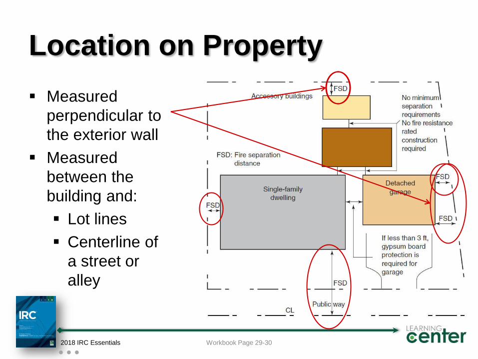
Location on Property
Measured
perpendicular to
the exterior wall
Measured
between the
building and:
Lot lines
Centerline of
a street or
alley
2018 IRC Essentials Workbook Page 29-30
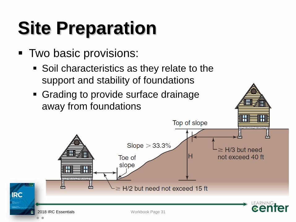
Site Preparation
Two basic provisions:
Soil characteristics as they relate to the
support and stability of foundations
Grading to provide surface drainage
away from foundations
2018 IRC Essentials Workbook Page 31
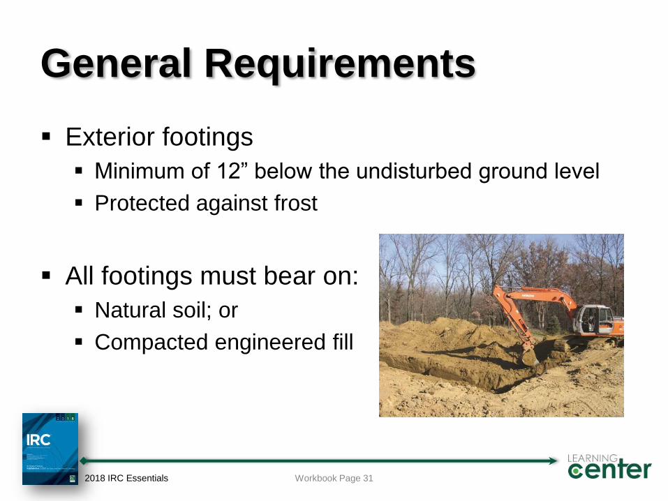
General Requirements
Exterior footings
Minimum of 12” below the undisturbed ground level
Protected against frost
All footings must bear on:
Natural soil; or
Compacted engineered fill
2018 IRC Essentials Workbook Page 31
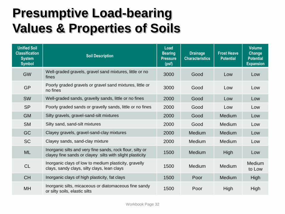
Presumptive Load-bearing
Values & Properties of Soils
Unified Soil
Classification
System
Symbol
Soil Description
Load
Bearing
Pressure
(psf)
Drainage
Characteristics
Frost Heave
Potential
Volume
Change
Potential
Expansion
GWWell-graded gravels, gravel sand mixtures, little or no
fines3000 Good Low Low
GPPoorly graded gravels or gravel sand mixtures, little or
no fines3000 Good Low Low
SW Well-graded sands, gravelly sands, little or no fines 2000 Good Low Low
SP Poorly graded sands or gravelly sands, little or no fines 2000 Good Low Low
GM Silty gravels, gravel-sand-silt mixtures 2000 Good Medium Low
SM Silty sand, sand-silt mixtures 2000 Good Medium Low
GC Clayey gravels, gravel-sand-clay mixtures 2000 Medium Medium Low
SC Clayey sands, sand-clay mixture 2000 Medium Medium Low
MLInorganic silts and very fine sands, rock flour, silty or
clayey fine sands or clayey silts with slight plasticity1500 Medium High Low
CLInorganic clays of low to medium plasticity, gravelly
clays, sandy clays, silty clays, lean clays 1500 Medium MediumMedium
to Low
CH Inorganic clays of high plasticity, fat clays 1500 Poor Medium High
MHInorganic silts, micaceous or diatomaceous fine sandy
or silty soils, elastic silts1500 Poor High High
Workbook Page 32
Fill
Engineered fill is required for:
Over-excavation to remove unsuitable soils
Additional material to raise the elevation of the
footings above the existing undisturbed soil
Engineered fill must be:
Designed by a registered design professional
Installed as specified in design requirements
Tested as specified in design requirements
2018 IRC Essentials Workbook Page 33
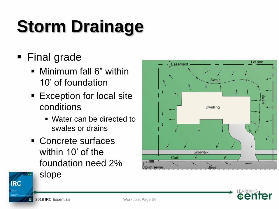
Storm Drainage
Final grade
Minimum fall 6” within
10’ of foundation
Exception for local site
conditions
Water can be directed to
swales or drains
Concrete surfaces
within 10’ of the
foundation need 2%
slope
2018 IRC Essentials Workbook Page 34
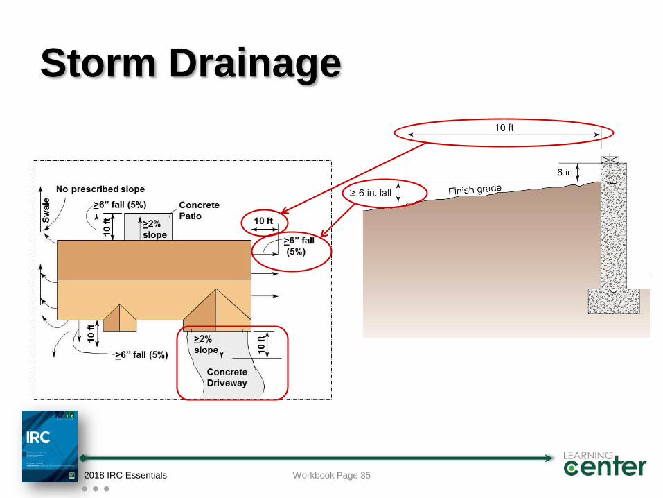
Storm Drainage
2018 IRC Essentials Workbook Page 35
Structural
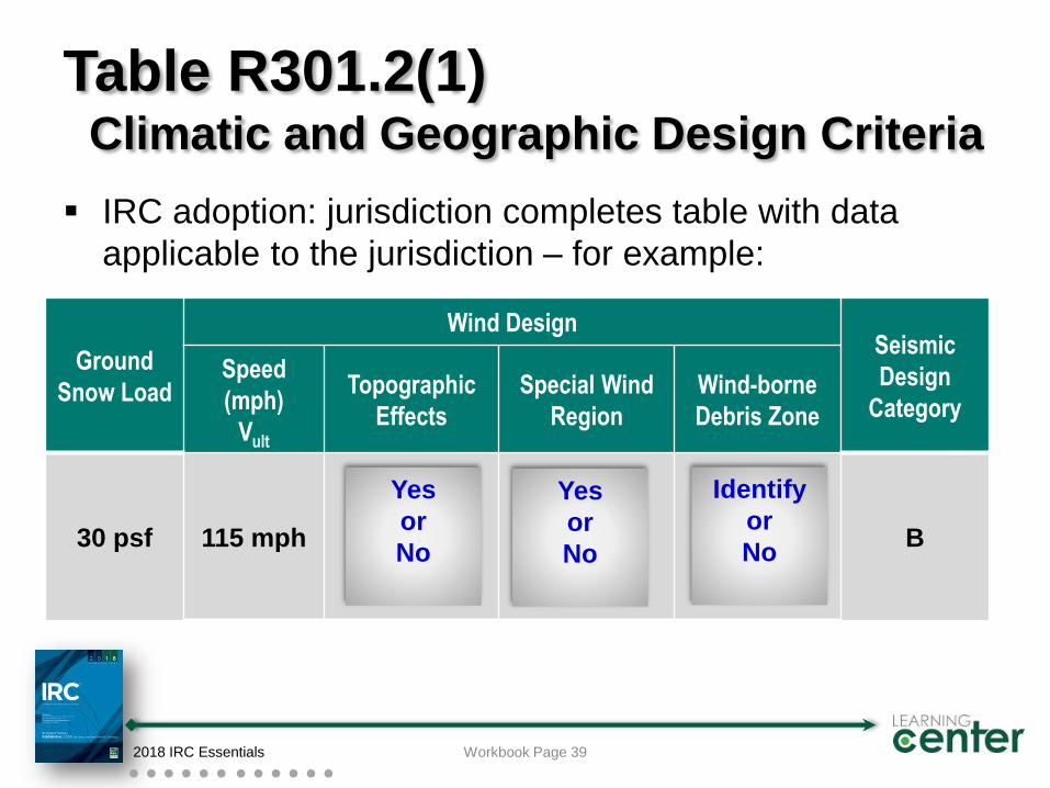
Ground
Snow Load
Wind DesignSeismic
Design
Category
Speed
(mph)
Vult
Topographic
Effects
Special Wind
Region
Wind-borne
Debris Zone
30 psf 115 mph B
Table R301.2(1)Climatic and Geographic Design Criteria
IRC adoption: jurisdiction completes table with data
applicable to the jurisdiction – for example:
2018 IRC Essentials
Yes
or
No
Workbook Page 39
Yes
or
No
Identify
or
No
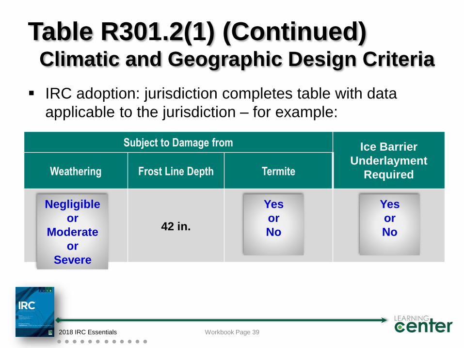
Subject to Damage from Ice Barrier
Underlayment
RequiredWeathering Frost Line Depth Termite
42 in.
Table R301.2(1) (Continued)Climatic and Geographic Design Criteria
IRC adoption: jurisdiction completes table with data
applicable to the jurisdiction – for example:
2018 IRC Essentials
Negligible
or
Moderate
or
Severe
Yes
or
No
Workbook Page 39
Yes
or
No
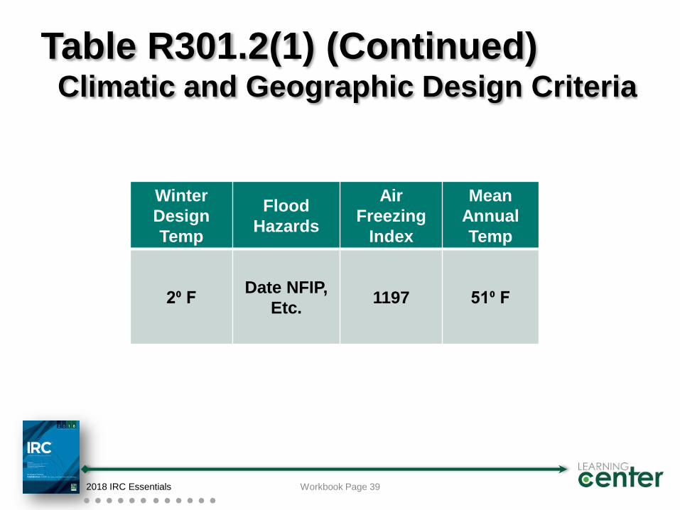
Winter
Design
Temp
Flood
Hazards
Air
Freezing
Index
Mean
Annual
Temp
2⁰ FDate NFIP,
Etc.1197 51⁰ F
Table R301.2(1) (Continued)Climatic and Geographic Design Criteria
2018 IRC Essentials Workbook Page 39
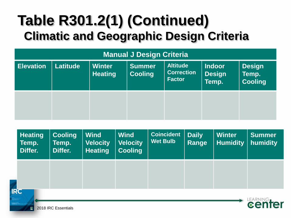
Table R301.2(1) (Continued)Climatic and Geographic Design Criteria
Elevation Latitude Winter
Heating
Summer
Cooling
Altitude
Correction
Factor
Indoor
Design
Temp.
Design
Temp.
Cooling
2018 IRC Essentials
Manual J Design Criteria
Heating
Temp.
Differ.
Cooling
Temp.
Differ.
Wind
Velocity
Heating
Wind
Velocity
Cooling
Coincident
Wet BulbDaily
Range
Winter
Humidity
Summer
humidity
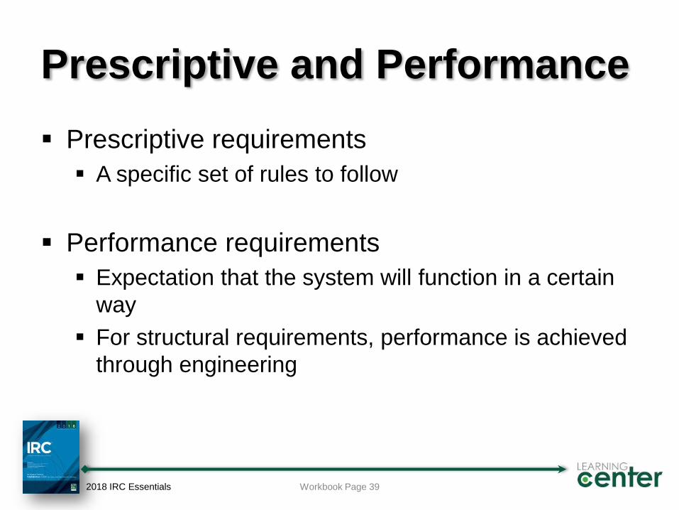
Prescriptive and Performance
Prescriptive requirements
A specific set of rules to follow
Performance requirements
Expectation that the system will function in a certain
way
For structural requirements, performance is achieved
through engineering
2018 IRC Essentials Workbook Page 39
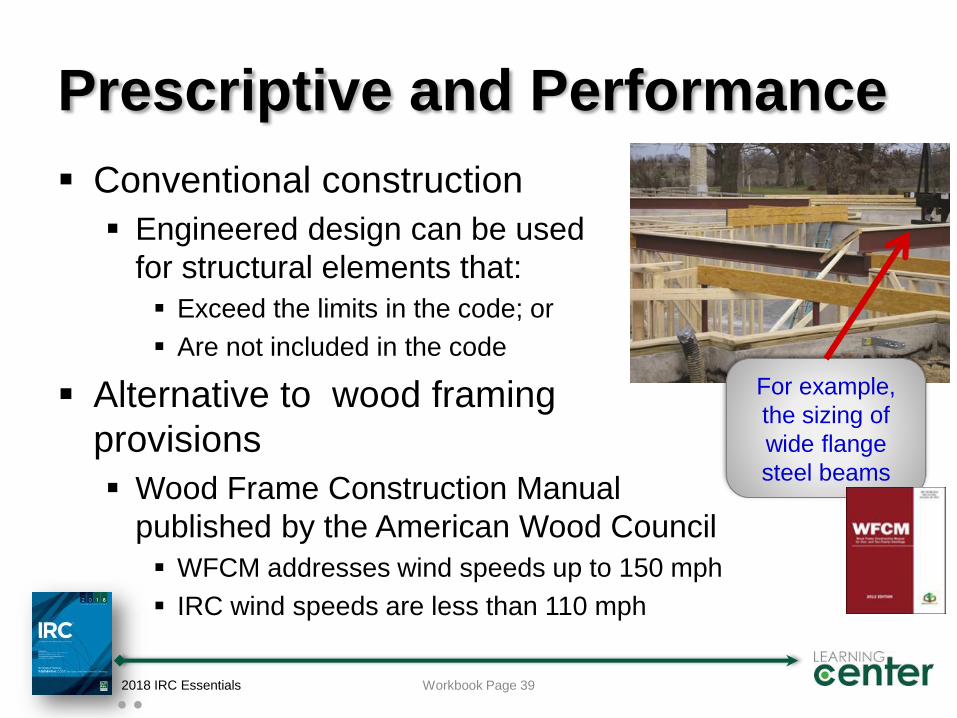
Prescriptive and Performance
Conventional construction
Engineered design can be used
for structural elements that:
Exceed the limits in the code; or
Are not included in the code
Alternative to wood framing
provisions
Wood Frame Construction Manual
published by the American Wood Council
WFCM addresses wind speeds up to 150 mph
IRC wind speeds are less than 110 mph
2018 IRC Essentials Workbook Page 39
For example,
the sizing of
wide flange
steel beams
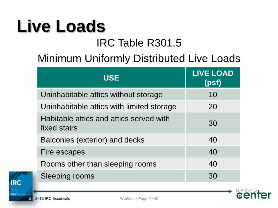
Live LoadsIRC Table R301.5
Minimum Uniformly Distributed Live Loads
2018 IRC Essentials
USELIVE LOAD
(psf)
Uninhabitable attics without storage 10
Uninhabitable attics with limited storage 20
Habitable attics and attics served with
fixed stairs 30
Balconies (exterior) and decks 40
Fire escapes 40
Rooms other than sleeping rooms 40
Sleeping rooms 30
Workbook Page 40-42
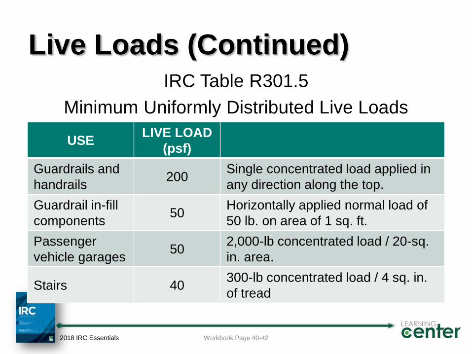
Live Loads (Continued)IRC Table R301.5
Minimum Uniformly Distributed Live Loads
2018 IRC Essentials
USELIVE LOAD
(psf)
Guardrails and
handrails200
Single concentrated load applied in
any direction along the top.
Guardrail in-fill
components50
Horizontally applied normal load of
50 lb. on area of 1 sq. ft.
Passenger
vehicle garages50
2,000-lb concentrated load / 20-sq.
in. area.
Stairs 40300-lb concentrated load / 4 sq. in.
of tread
Workbook Page 40-42
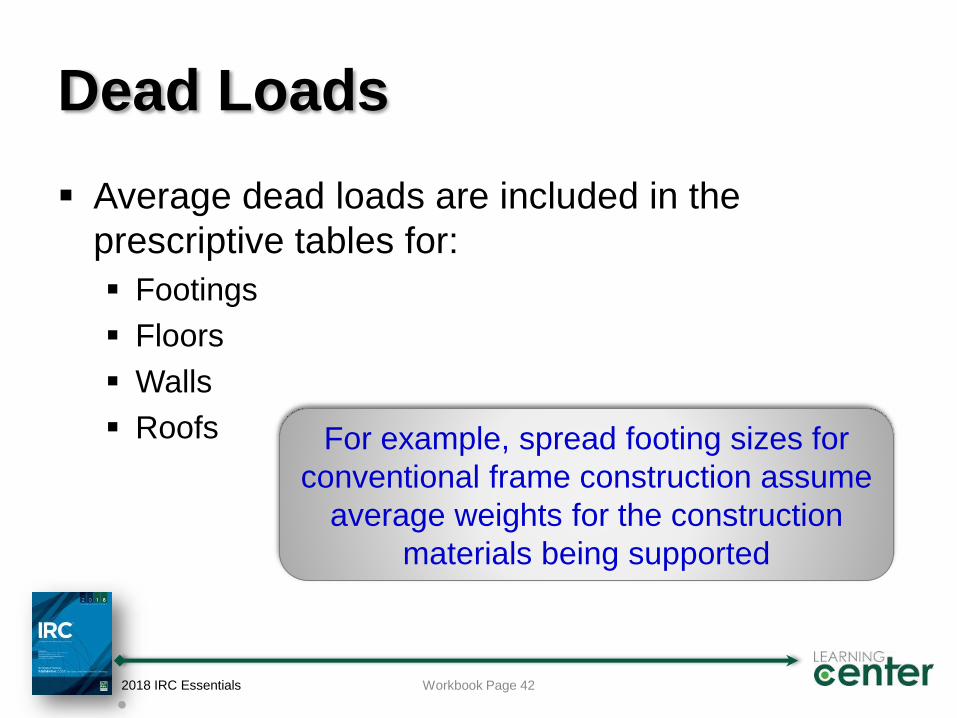
Dead Loads
Average dead loads are included in the
prescriptive tables for:
Footings
Floors
Walls
Roofs
2018 IRC Essentials Workbook Page 42
For example, spread footing sizes for
conventional frame construction assume
average weights for the construction
materials being supported
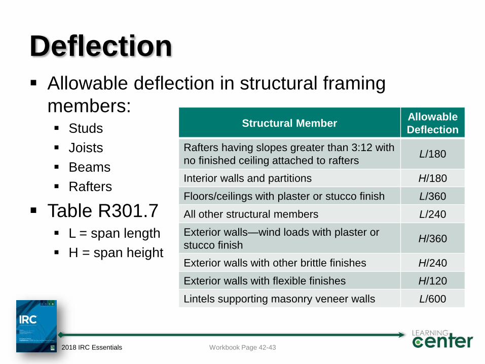
Deflection Allowable deflection in structural framing
members: Studs
Joists
Beams
Rafters
Table R301.7 L = span length
H = span height
2018 IRC Essentials Workbook Page 42-43
Structural MemberAllowable
Deflection
Rafters having slopes greater than 3:12 with
no finished ceiling attached to raftersL/180
Interior walls and partitions H/180
Floors/ceilings with plaster or stucco finish L/360
All other structural members L/240
Exterior walls—wind loads with plaster or
stucco finishH/360
Exterior walls with other brittle finishes H/240
Exterior walls with flexible finishes H/120
Lintels supporting masonry veneer walls L/600
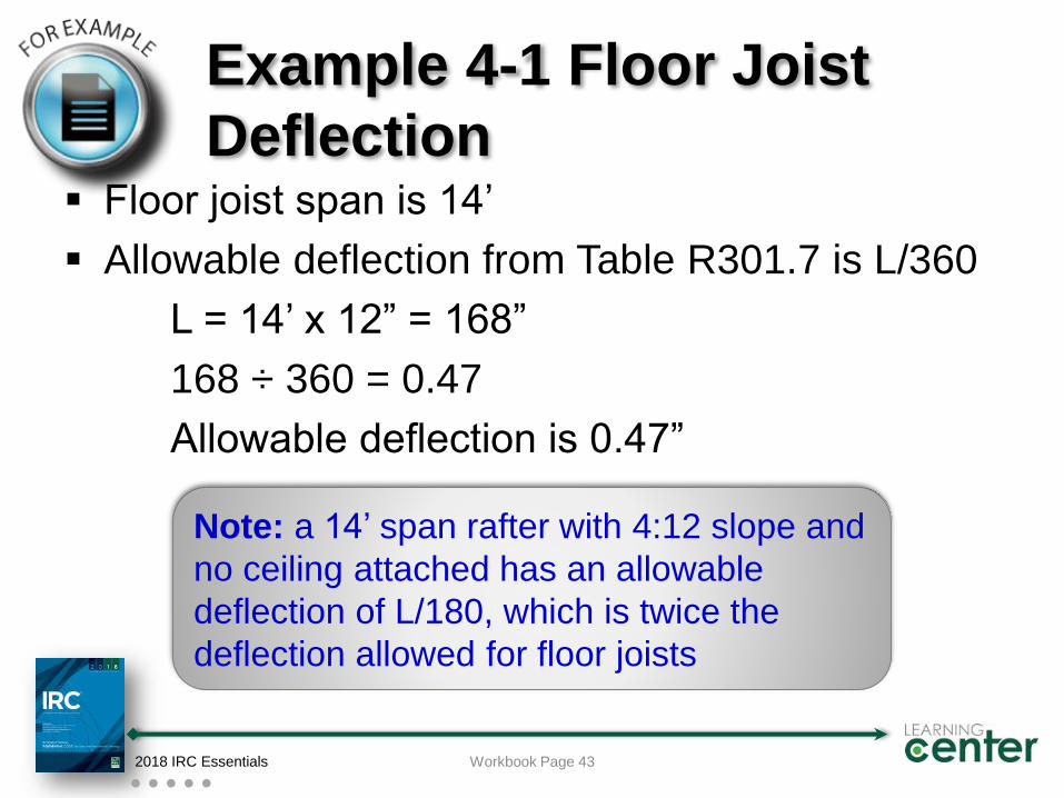
Example 4-1 Floor Joist
Deflection Floor joist span is 14’
Allowable deflection from Table R301.7 is L/360
L = 14’ x 12” = 168”
168 ÷ 360 = 0.47
Allowable deflection is 0.47”
2018 IRC Essentials Workbook Page 43
Note: a 14’ span rafter with 4:12 slope and
no ceiling attached has an allowable
deflection of L/180, which is twice the
deflection allowed for floor joists
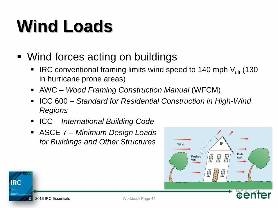
Wind Loads
Wind forces acting on buildings IRC conventional framing limits wind speed to 140 mph Vult (130
in hurricane prone areas)
AWC – Wood Framing Construction Manual (WFCM)
ICC 600 – Standard for Residential Construction in High-Wind
Regions
ICC – International Building Code
ASCE 7 – Minimum Design Loads
for Buildings and Other Structures
2018 IRC Essentials Workbook Page 44
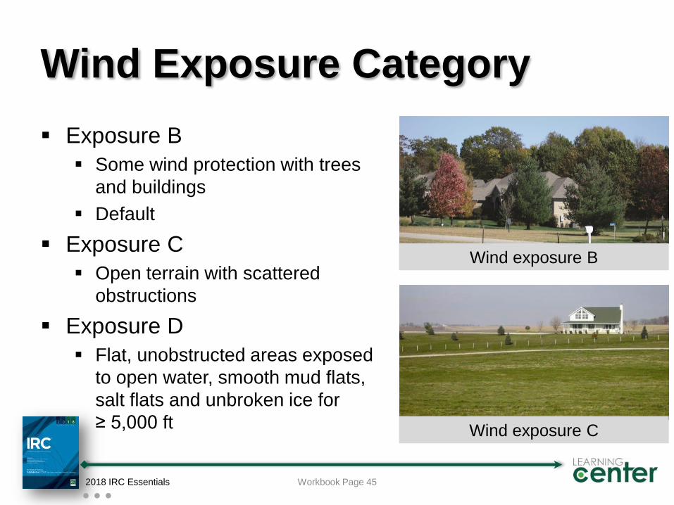
Wind Exposure Category
Exposure B
Some wind protection with trees
and buildings
Default
Exposure C
Open terrain with scattered
obstructions
Exposure D
Flat, unobstructed areas exposed
to open water, smooth mud flats,
salt flats and unbroken ice for
≥ 5,000 ft
2018 IRC Essentials Workbook Page 45
Wind exposure C
Wind exposure B
Hurricane-prone regions
Hurricane-prone regions. Areas vulnerable to hurricanes, defined
as the U.S. Atlantic Ocean and Gulf of Mexico coasts where the
ultimate design wind speed, Vult, is greater than 115 miles per hour ,
and Hawaii, Puerto Rico, Guam, Virgin Islands and America Samoa.
Windborne debris region. Areas within hurricane-prone regions
located in accordance with one of the following:
1.Within 1 mile of the coastal mean high water line where the ultimate
design wind speed, Vult, is 130 mph or greater.
2. In areas where the ultimate design wind speed, Vult, is 140 mph or
greater; or Hawaii.
2018 IRC Essentials Workbook Page 46
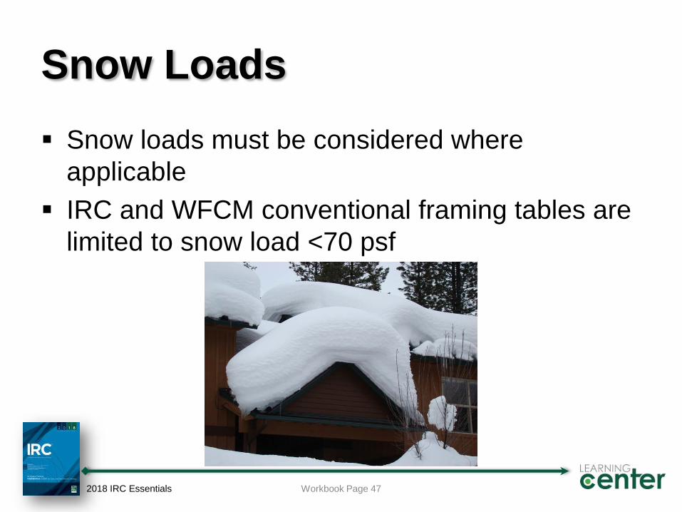
Snow Loads
Snow loads must be considered where
applicable
IRC and WFCM conventional framing tables are
limited to snow load <70 psf
2018 IRC Essentials Workbook Page 47
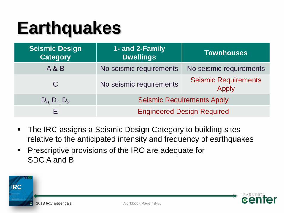
Earthquakes
The IRC assigns a Seismic Design Category to building sites
relative to the anticipated intensity and frequency of earthquakes
Prescriptive provisions of the IRC are adequate for
SDC A and B
2018 IRC Essentials Workbook Page 48-50
Seismic Design
Category
1- and 2-Family
DwellingsTownhouses
A & B No seismic requirements No seismic requirements
C No seismic requirementsSeismic Requirements
Apply
D0, D1, D2 Seismic Requirements Apply
E Engineered Design Required
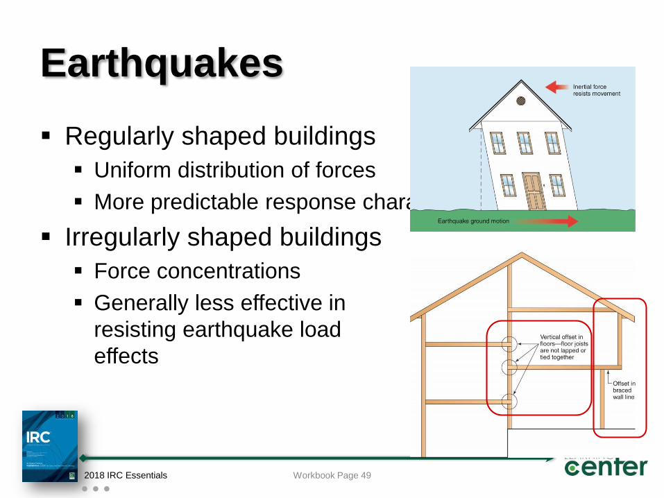
Earthquakes
Regularly shaped buildings
Uniform distribution of forces
More predictable response characteristics
Irregularly shaped buildings
Force concentrations
Generally less effective in
resisting earthquake load
effects
2018 IRC Essentials Workbook Page 49
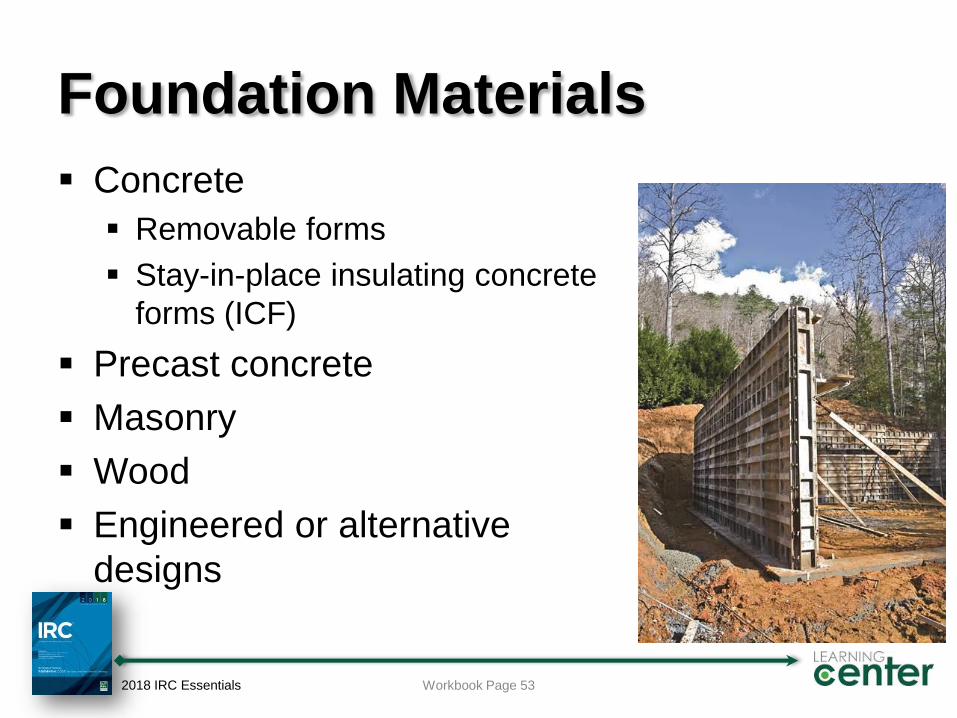
Foundation Materials
Concrete
Removable forms
Stay-in-place insulating concrete
forms (ICF)
Precast concrete
Masonry
Wood
Engineered or alternative
designs
2018 IRC Essentials Workbook Page 53
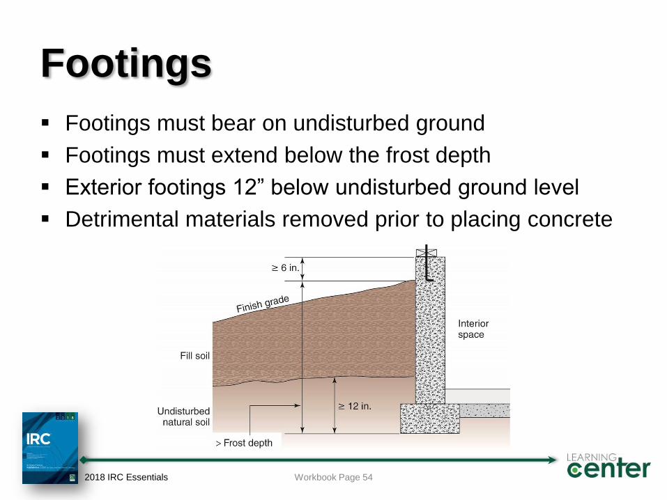
Footings
Footings must bear on undisturbed ground
Footings must extend below the frost depth
Exterior footings 12” below undisturbed ground level
Detrimental materials removed prior to placing concrete
2018 IRC Essentials Workbook Page 54
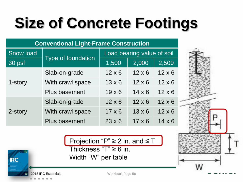
Size of Concrete Footings
Conventional Light-Frame Construction
Snow loadType of foundation
Load bearing value of soil
30 psf 1,500 2,000 2,500
1-story
Slab-on-grade 12 x 6 12 x 6 12 x 6
With crawl space 13 x 6 12 x 6 12 x 6
Plus basement 19 x 6 14 x 6 12 x 6
2-story
Slab-on-grade 12 x 6 12 x 6 12 x 6
With crawl space 17 x 6 13 x 6 12 x 6
Plus basement 23 x 6 17 x 6 14 x 6
2018 IRC Essentials Workbook Page 56
Projection “P” ≥ 2 in. and ≤ T
Thickness “T” ≥ 6 in.
Width “W” per table
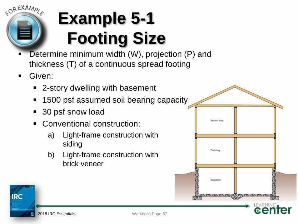
Example 5-1
Footing Size Determine minimum width (W), projection (P) and
thickness (T) of a continuous spread footing
Given:
2-story dwelling with basement
1500 psf assumed soil bearing capacity
30 psf snow load
Conventional construction:
a) Light-frame construction with
siding
b) Light-frame construction with
brick veneer
2018 IRC Essentials Workbook Page 57
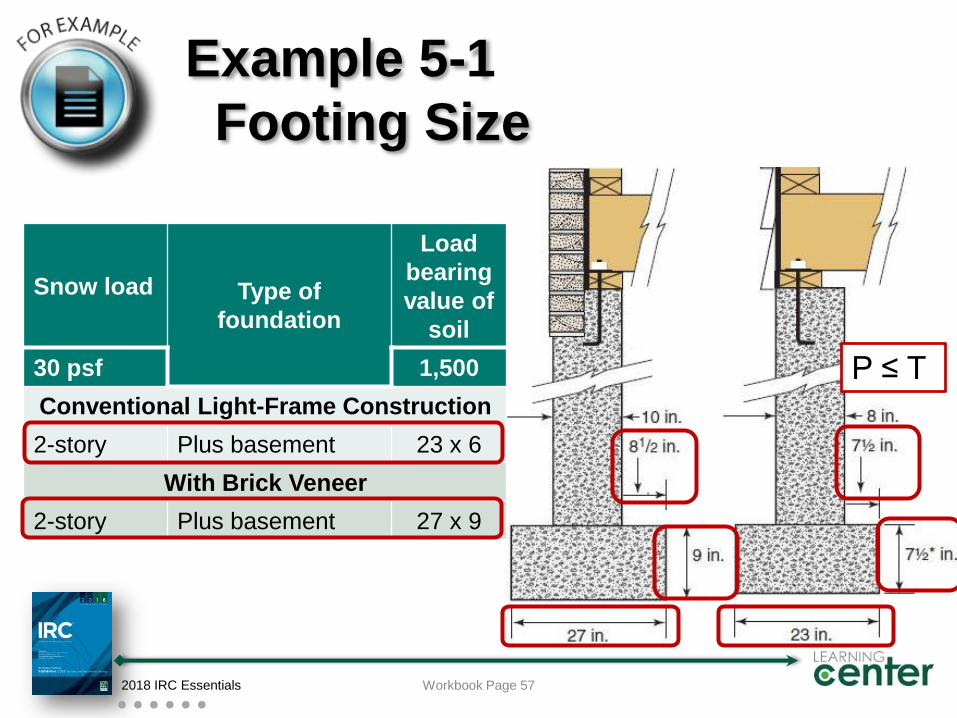
Example 5-1
Footing Size
Snow load Type of
foundation
Load
bearing
value of
soil
30 psf 1,500
Conventional Light-Frame Construction
2-story Plus basement 23 x 6
With Brick Veneer
2-story Plus basement 27 x 9
2018 IRC Essentials Workbook Page 57
P ≤ T
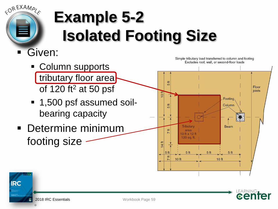
Example 5-2
Isolated Footing Size Given:
Column supports
tributary floor area
of 120 ft2 at 50 psf
1,500 psf assumed soil-
bearing capacity
Determine minimum
footing size
2018 IRC Essentials Workbook Page 59
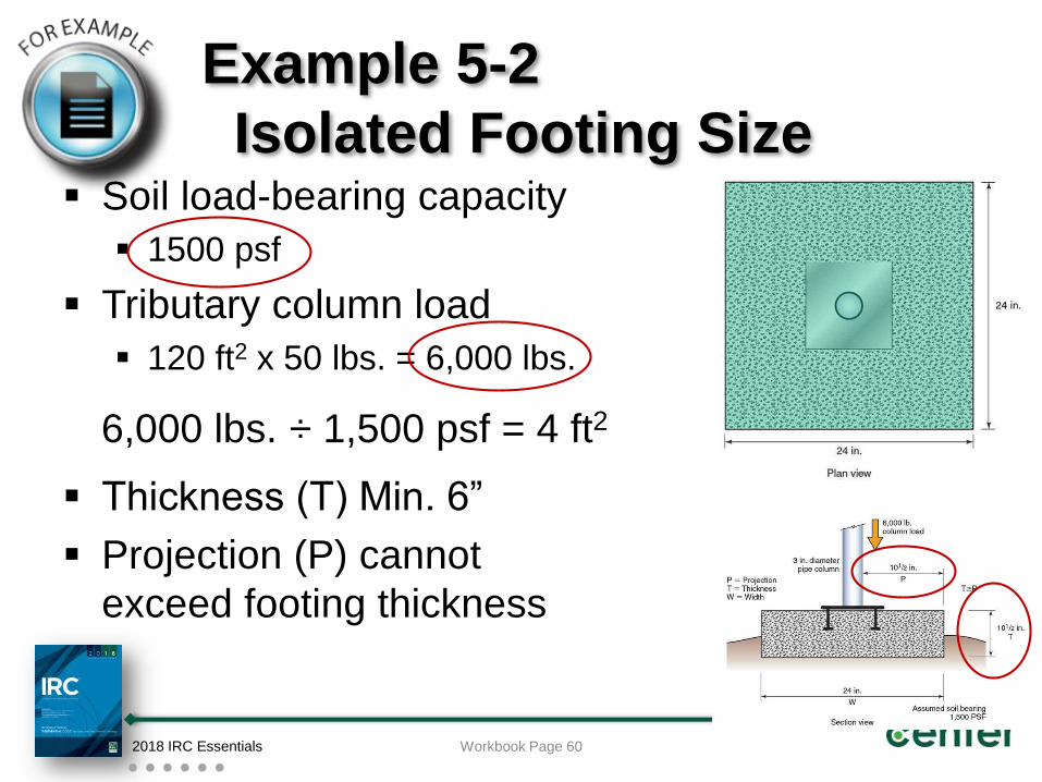
Example 5-2
Isolated Footing Size Soil load-bearing capacity
1500 psf
Tributary column load
120 ft2 x 50 lbs. = 6,000 lbs.
Thickness (T) Min. 6”
Projection (P) cannot
exceed footing thickness
2018 IRC Essentials Workbook Page 60
6,000 lbs. ÷ 1,500 psf = 4 ft2
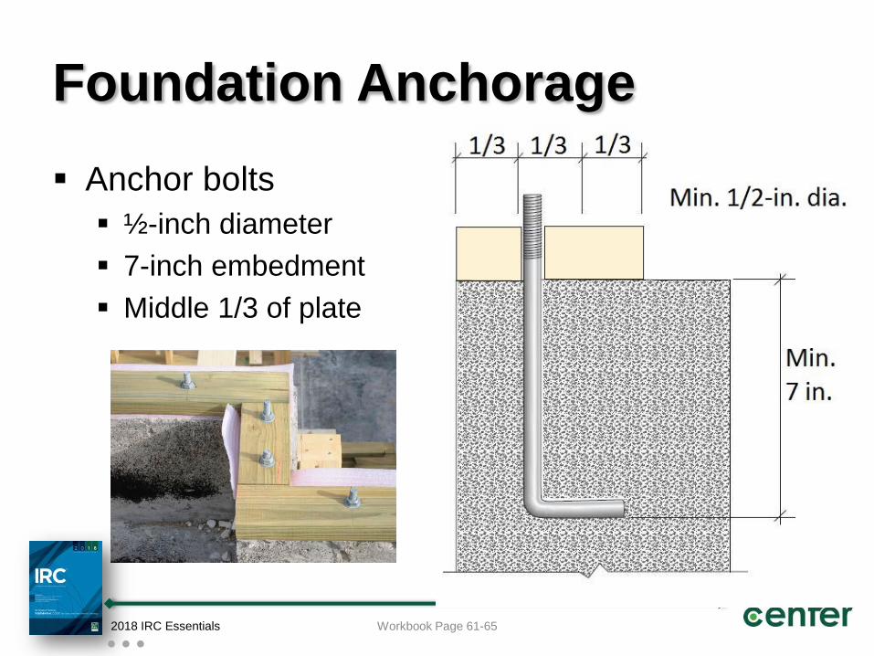
Foundation Anchorage
Anchor bolts
½-inch diameter
7-inch embedment
Middle 1/3 of plate
2018 IRC Essentials Workbook Page 61-65
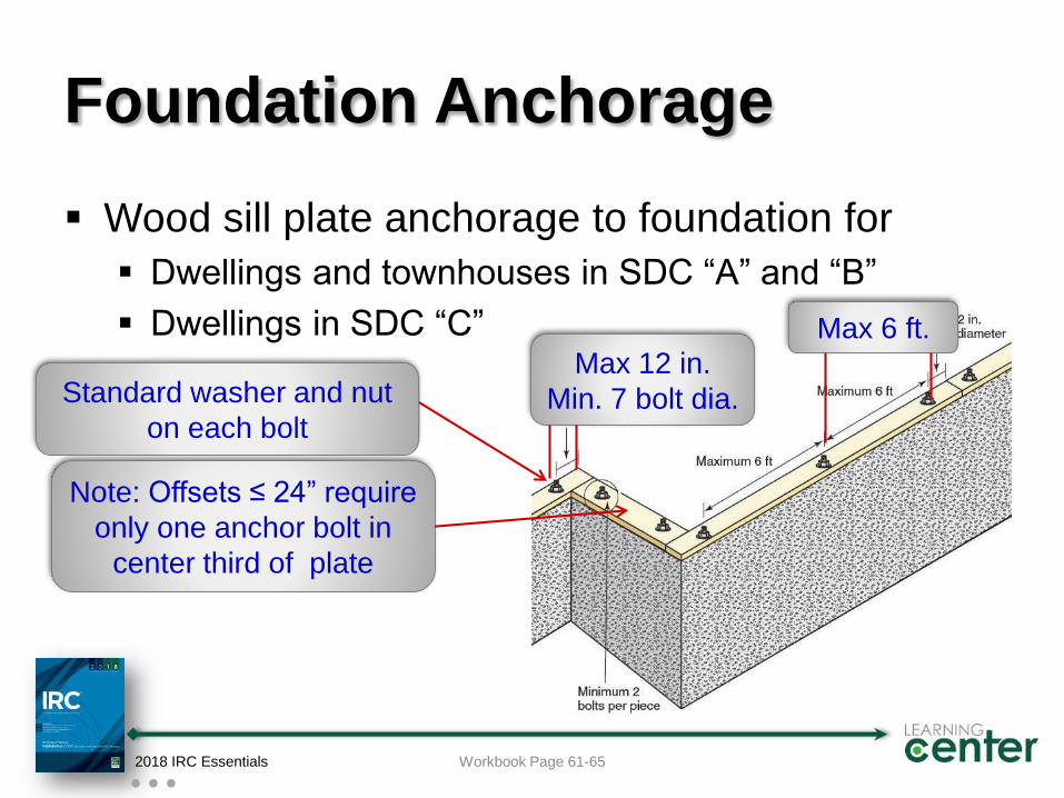
Foundation Anchorage
Wood sill plate anchorage to foundation for
Dwellings and townhouses in SDC “A” and “B”
Dwellings in SDC “C”
2018 IRC Essentials Workbook Page 61-65
Note: Offsets ≤ 24” require
only one anchor bolt in
center third of plate
Max 12 in.
Min. 7 bolt dia.
Max 6 ft.
Standard washer and nut
on each bolt
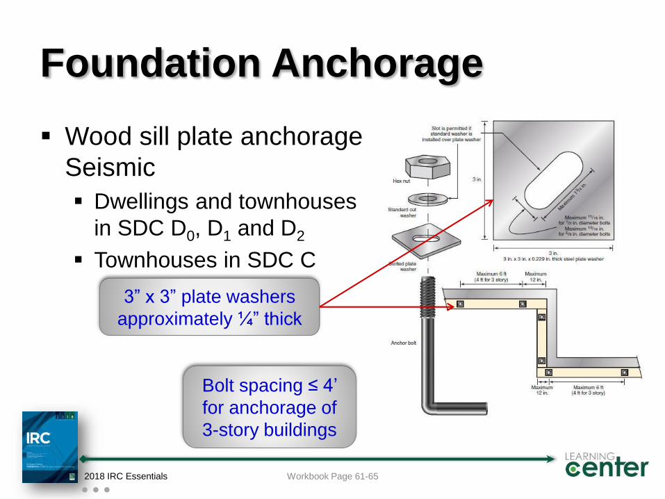
Foundation Anchorage
Wood sill plate anchorage
Seismic
Dwellings and townhouses
in SDC D0, D1 and D2
Townhouses in SDC C
2018 IRC Essentials Workbook Page 61-65
3” x 3” plate washers
approximately ¼” thick
Bolt spacing ≤ 4’
for anchorage of
3-story buildings
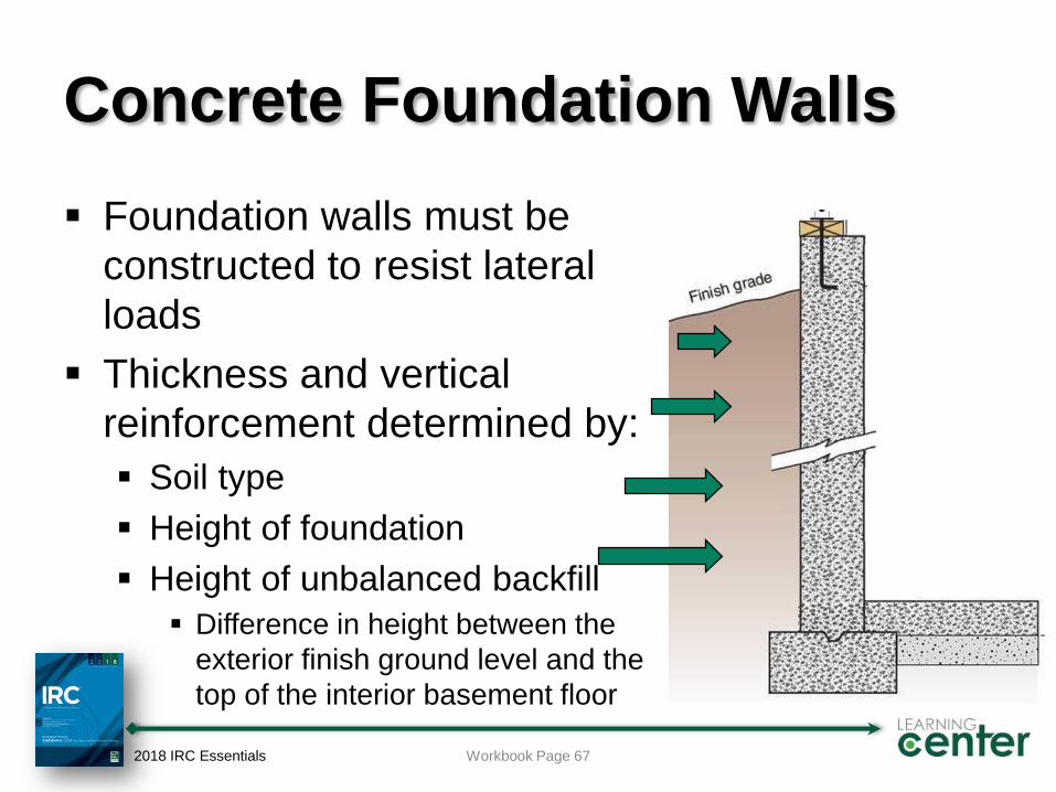
Concrete Foundation Walls
Foundation walls must be
constructed to resist lateral
loads
Thickness and vertical
reinforcement determined by:
Soil type
Height of foundation
Height of unbalanced backfill
Difference in height between the
exterior finish ground level and the
top of the interior basement floor
2018 IRC Essentials Workbook Page 67
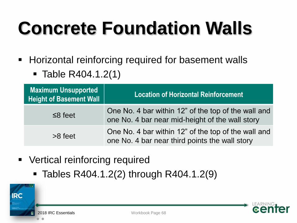
Concrete Foundation Walls
Horizontal reinforcing required for basement walls
Table R404.1.2(1)
Vertical reinforcing required
Tables R404.1.2(2) through R404.1.2(9)
2018 IRC Essentials Workbook Page 68
Maximum Unsupported
Height of Basement WallLocation of Horizontal Reinforcement
≤8 feetOne No. 4 bar within 12” of the top of the wall and
one No. 4 bar near mid-height of the wall story
>8 feetOne No. 4 bar within 12” of the top of the wall and
one No. 4 bar near third points the wall story
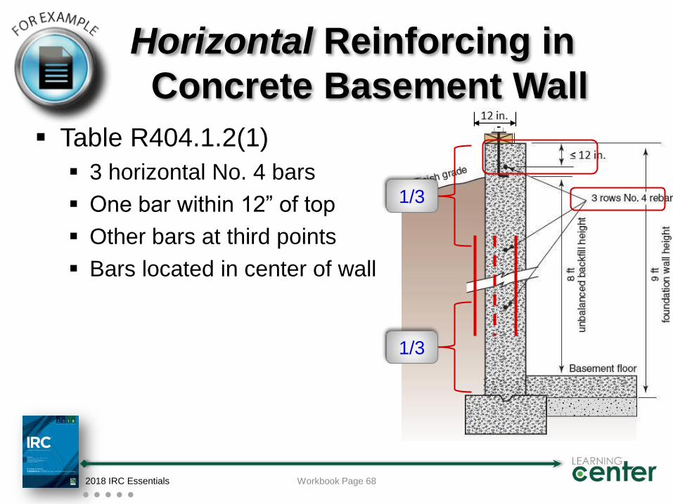
Horizontal Reinforcing in
Concrete Basement Wall
Table R404.1.2(1)
3 horizontal No. 4 bars
One bar within 12” of top
Other bars at third points
Bars located in center of wall
2018 IRC Essentials
1/3
1/3
Workbook Page 68
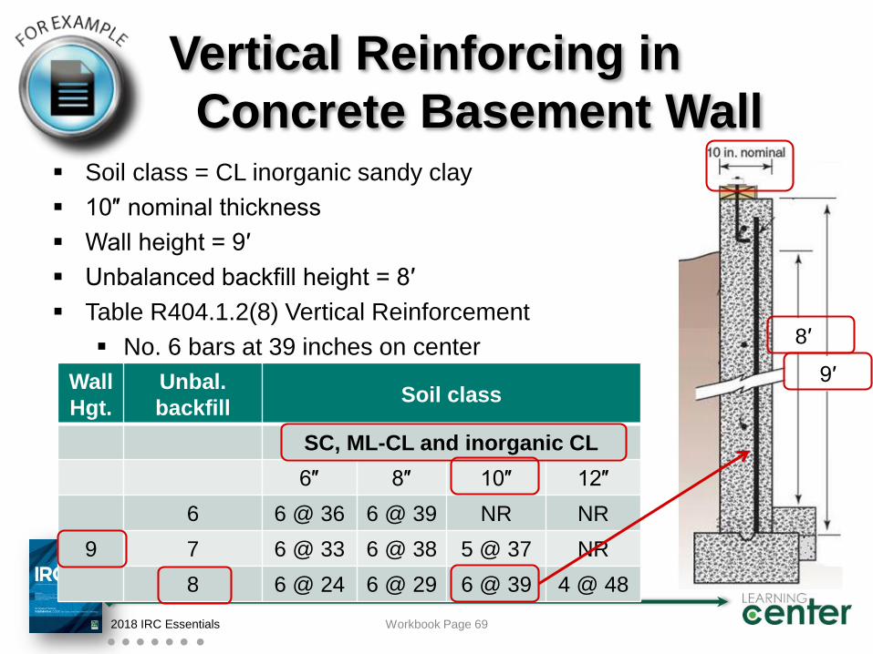
Vertical Reinforcing in
Concrete Basement Wall Soil class = CL inorganic sandy clay
10″ nominal thickness
Wall height = 9′
Unbalanced backfill height = 8′
Table R404.1.2(8) Vertical Reinforcement
No. 6 bars at 39 inches on center
2018 IRC Essentials Workbook Page 69
Wall
Hgt.
Unbal.
backfillSoil class
SC, ML-CL and inorganic CL
6″ 8″ 10″ 12″
9
6 6 @ 36 6 @ 39 NR NR
7 6 @ 33 6 @ 38 5 @ 37 NR
8 6 @ 24 6 @ 29 6 @ 39 4 @ 48
9′
8′
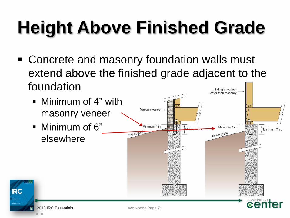
Height Above Finished Grade
Concrete and masonry foundation walls must
extend above the finished grade adjacent to the
foundation
Minimum of 4” with
masonry veneer
Minimum of 6”
elsewhere
2018 IRC Essentials Workbook Page 71
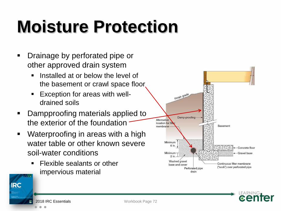
Moisture Protection
Drainage by perforated pipe or
other approved drain system
Installed at or below the level of
the basement or crawl space floor
Exception for areas with well-
drained soils
Dampproofing materials applied to
the exterior of the foundation
Waterproofing in areas with a high
water table or other known severe
soil-water conditions
Flexible sealants or other
impervious material
2018 IRC Essentials Workbook Page 72
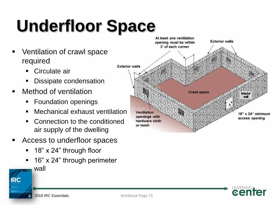
Underfloor Space
Ventilation of crawl space
required
Circulate air
Dissipate condensation
Method of ventilation
Foundation openings
Mechanical exhaust ventilation
Connection to the conditioned
air supply of the dwelling
Access to underfloor spaces
18” x 24” through floor
16” x 24” through perimeter
wall
2018 IRC Essentials Workbook Page 73
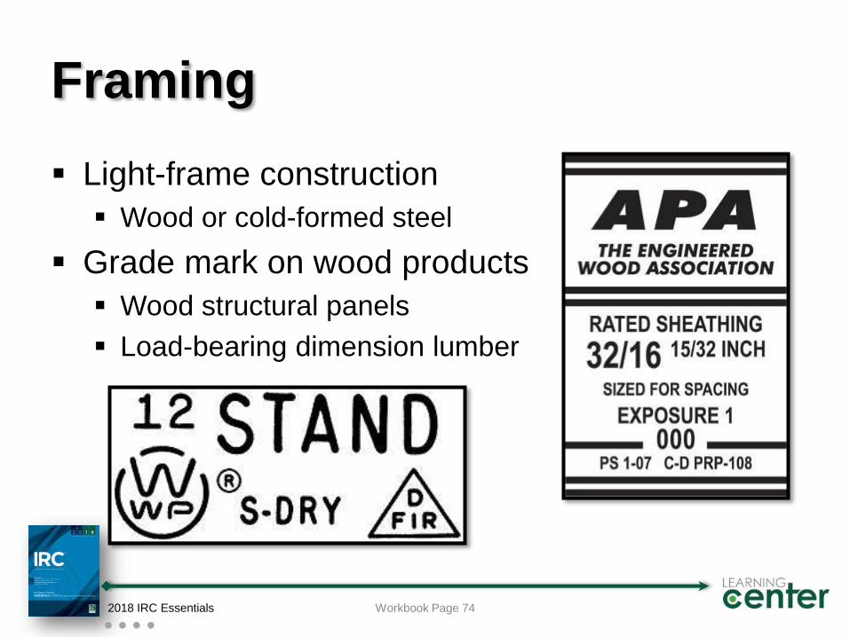
Framing
Light-frame construction
Wood or cold-formed steel
Grade mark on wood products
Wood structural panels
Load-bearing dimension lumber
2018 IRC Essentials Workbook Page 74
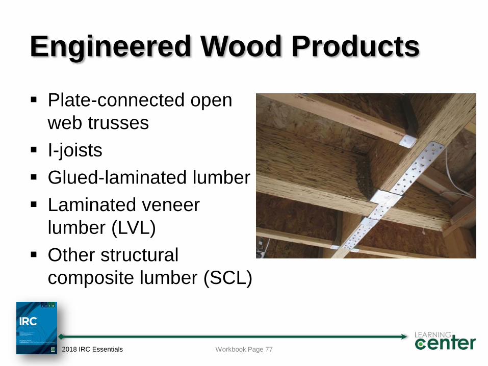
Engineered Wood Products
Plate-connected open
web trusses
I-joists
Glued-laminated lumber
Laminated veneer
lumber (LVL)
Other structural
composite lumber (SCL)
2018 IRC Essentials Workbook Page 77
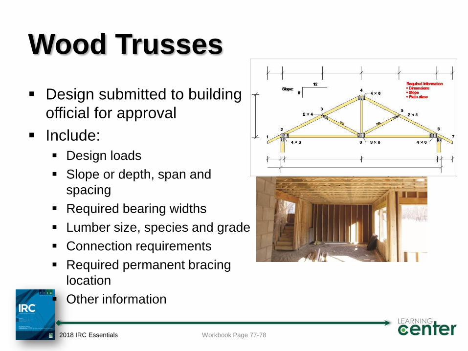
Wood Trusses
Design submitted to building
official for approval
Include:
Design loads
Slope or depth, span and
spacing
Required bearing widths
Lumber size, species and grade
Connection requirements
Required permanent bracing
location
Other information
2018 IRC Essentials Workbook Page 77-78
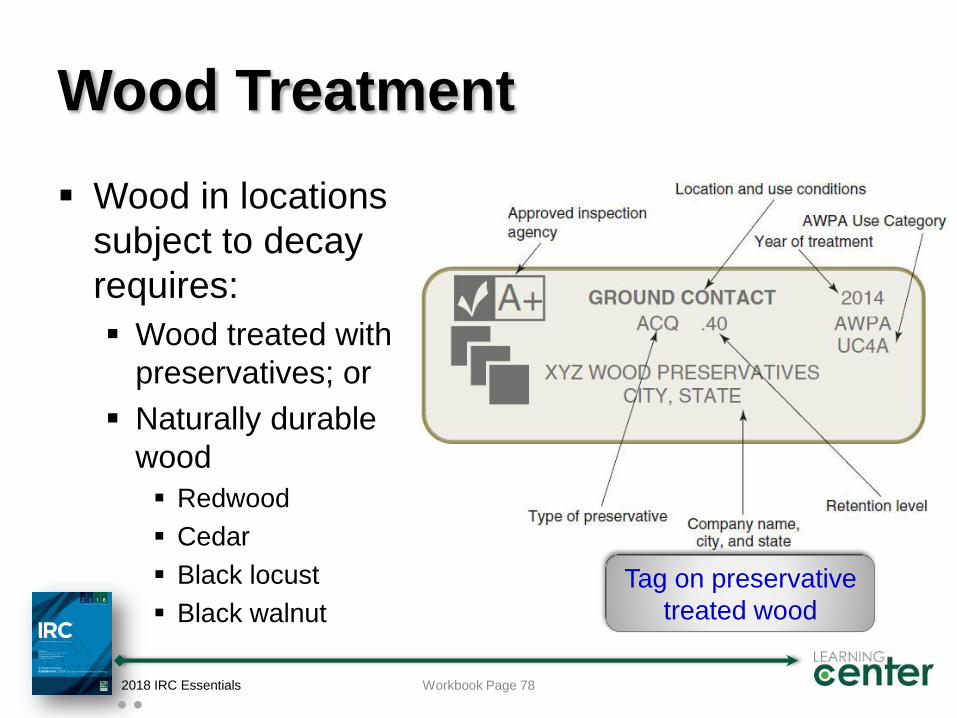
Wood Treatment
Wood in locations
subject to decay
requires:
Wood treated with
preservatives; or
Naturally durable
wood
Redwood
Cedar
Black locust
Black walnut
2018 IRC Essentials Workbook Page 78
Tag on preservative
treated wood
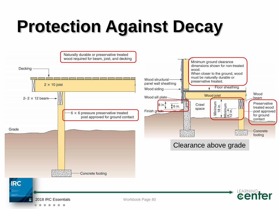
Protection Against Decay
2018 IRC Essentials Workbook Page 80
Clearance above grade
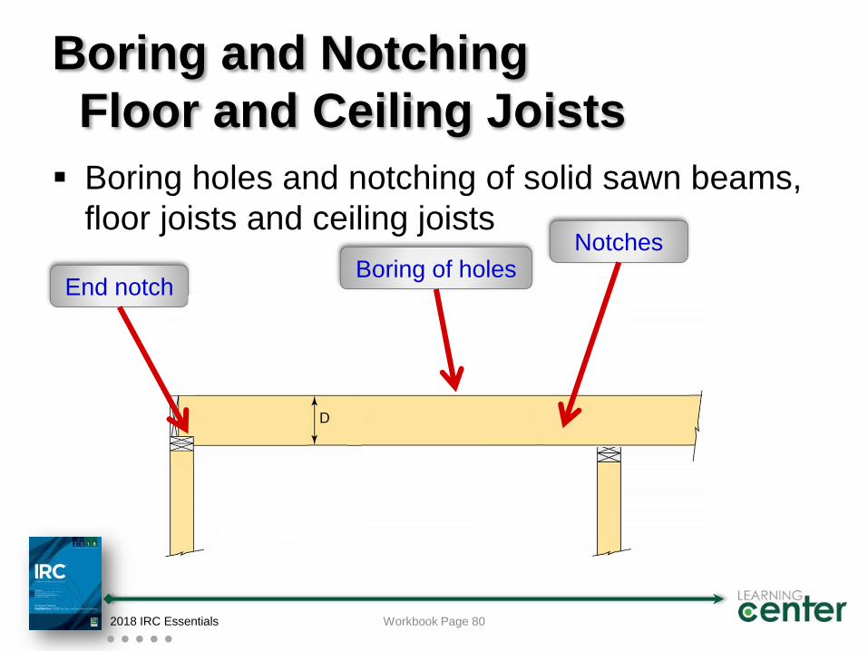
Boring and Notching
Floor and Ceiling Joists
Boring holes and notching of solid sawn beams,
floor joists and ceiling joists
2018 IRC Essentials Workbook Page 80
End notch
NotchesBoring of holes
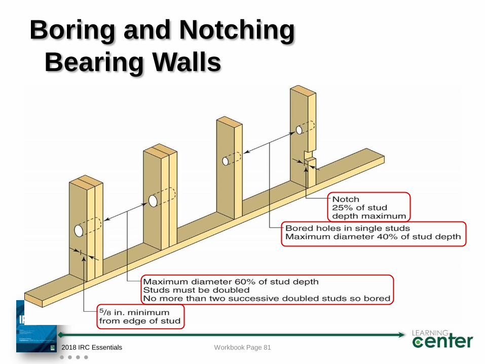
Boring and Notching
Bearing Walls
2018 IRC Essentials Workbook Page 81
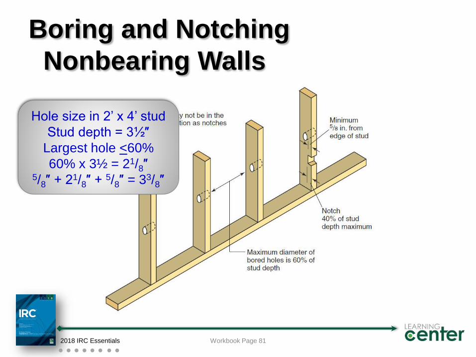
Boring and Notching
Nonbearing Walls
2018 IRC Essentials Workbook Page 81
Hole size in 2’ x 4’ stud
Stud depth = 3½″
Largest hole <60%
60% x 3½ = 21/8″5/8″ + 21/8″ + 5/8″ = 33/8″
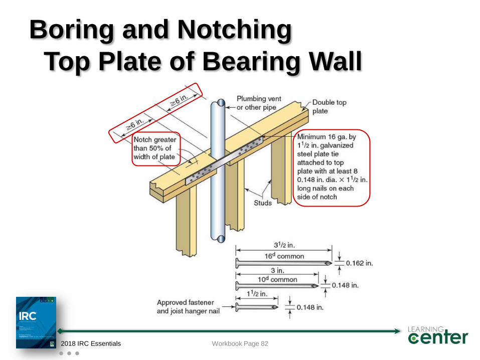
Boring and Notching
Top Plate of Bearing Wall
2018 IRC Essentials Workbook Page 82
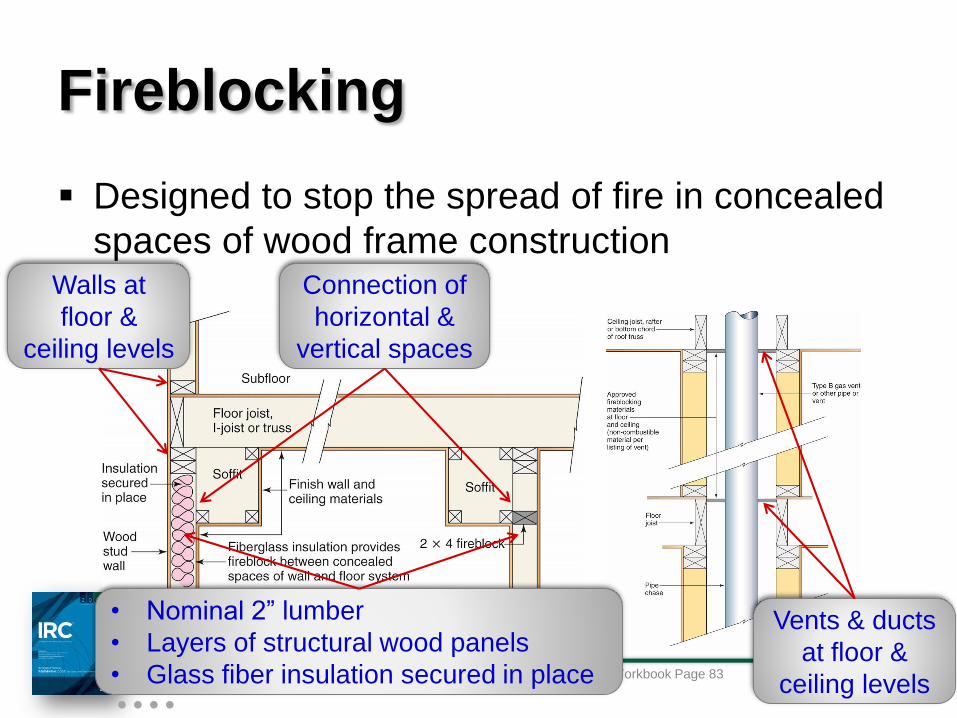
Fireblocking
Designed to stop the spread of fire in concealed
spaces of wood frame construction
2018 IRC EssentialsWorkbook Page 83
Walls at
floor &
ceiling levels
Connection of
horizontal &
vertical spaces
• Nominal 2” lumber
• Layers of structural wood panels
• Glass fiber insulation secured in place
Vents & ducts
at floor &
ceiling levels
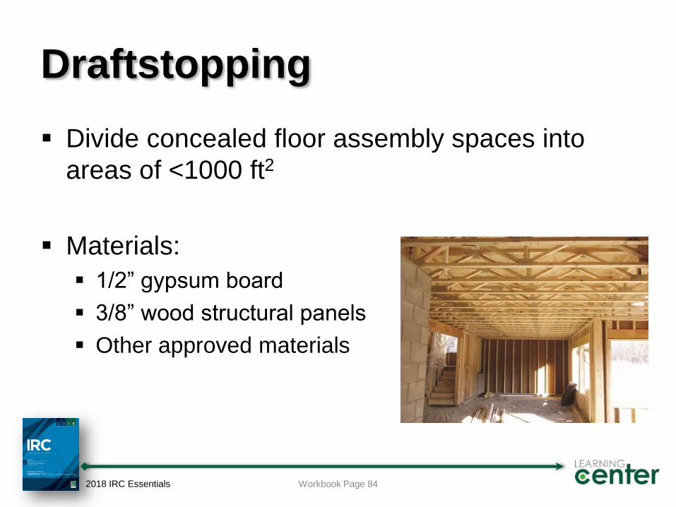
Draftstopping
Divide concealed floor assembly spaces into
areas of <1000 ft2
Materials:
1/2” gypsum board
3/8” wood structural panels
Other approved materials
2018 IRC Essentials Workbook Page 84
Wood Floor Framing
Prescriptive tables for:
Beams and girders
No. 2 grade Douglas fir-larch, hem-fir, southern pine and
spruce-pine-fir
Various support conditions
Floor joists
Specific grade and species of lumber
Live load 30 or 40 psf
Dead load 10 or 20 psf
2018 IRC Essentials Workbook Page 84
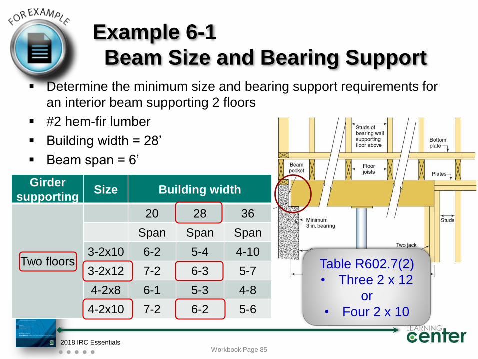
Girder
supportingSize Building width
Two floors
20 28 36
Span Span Span
3-2x10 6-2 5-4 4-10
3-2x12 7-2 6-3 5-7
4-2x8 6-1 5-3 4-8
4-2x10 7-2 6-2 5-6
Example 6-1
Beam Size and Bearing Support
Determine the minimum size and bearing support requirements for
an interior beam supporting 2 floors
#2 hem-fir lumber
Building width = 28’
Beam span = 6’
2018 IRC EssentialsWorkbook Page 85
Table R602.7(2)
• Three 2 x 12
or
• Four 2 x 10
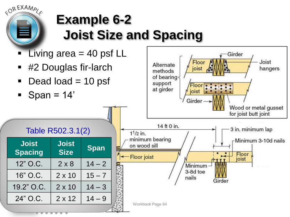
Example 6-2
Joist Size and Spacing
Living area = 40 psf LL
#2 Douglas fir-larch
Dead load = 10 psf
Span = 14’
2018 IRC EssentialsWorkbook Page 86
Table R502.3.1(2)
Joist
Spacing
Joist
SizeSpan
12” O.C. 2 x 8 14 – 2
16” O.C. 2 x 10 15 – 7
19.2” O.C. 2 x 10 14 – 3
24” O.C. 2 x 12 14 – 9Workbook Page 84
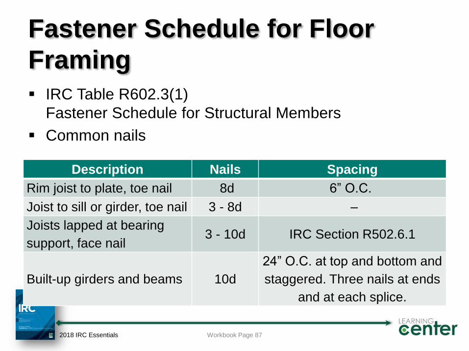
Fastener Schedule for Floor
Framing
IRC Table R602.3(1)
Fastener Schedule for Structural Members
Common nails
2018 IRC Essentials Workbook Page 87
Description Nails Spacing
Rim joist to plate, toe nail 8d 6” O.C.
Joist to sill or girder, toe nail 3 - 8d –
Joists lapped at bearing
support, face nail3 - 10d IRC Section R502.6.1
Built-up girders and beams 10d
24” O.C. at top and bottom and
staggered. Three nails at ends
and at each splice.
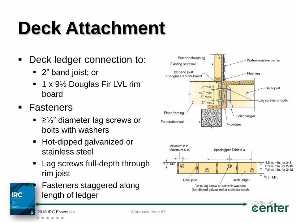
Deck Attachment
Deck ledger connection to:
2” band joist; or
1 x 9½ Douglas Fir LVL rim
board
Fasteners
≥½” diameter lag screws or
bolts with washers
Hot-dipped galvanized or
stainless steel
Lag screws full-depth through
rim joist
Fasteners staggered along
length of ledger
2018 IRC Essentials Workbook Page 87
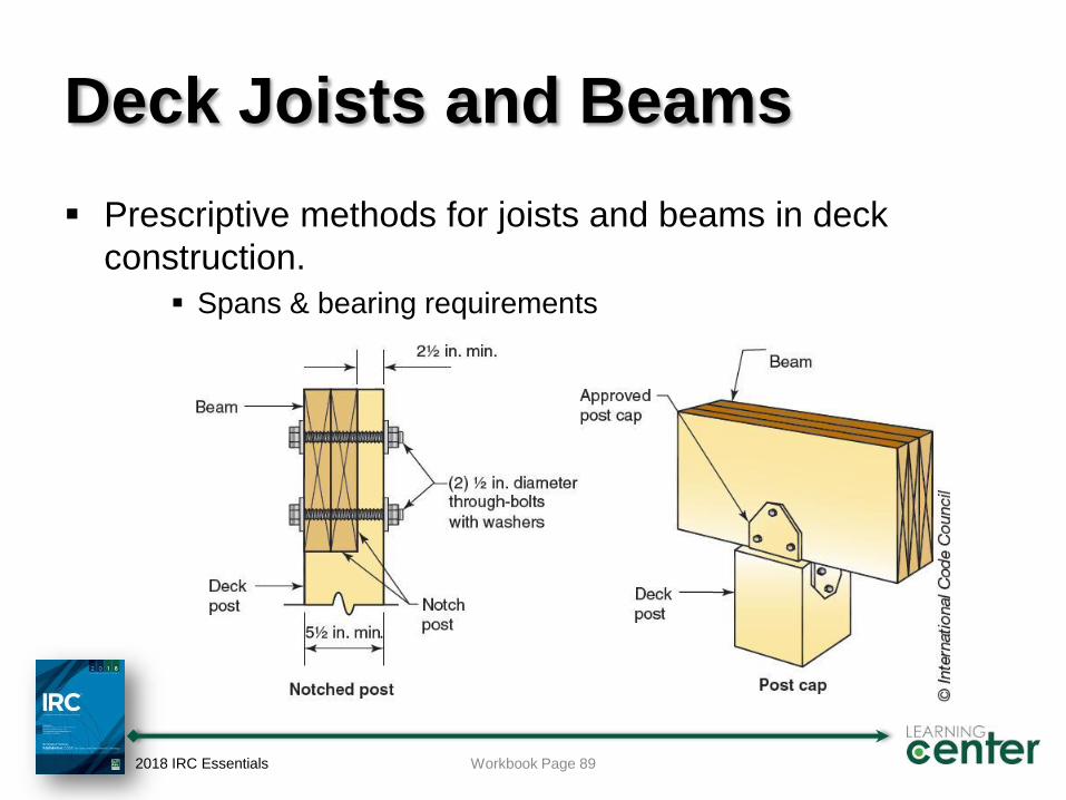
Deck Joists and Beams
Prescriptive methods for joists and beams in deck
construction.
Spans & bearing requirements
2018 IRC Essentials Workbook Page 89
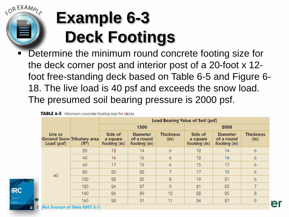
Example 6-3
Deck Footings Determine the minimum round concrete footing size for
the deck corner post and interior post of a 20-foot x 12-
foot free-standing deck based on Table 6-5 and Figure 6-
18. The live load is 40 psf and exceeds the snow load.
The presumed soil bearing pressure is 2000 psf.
2018 IRC Essentials Workbook Page 96-97
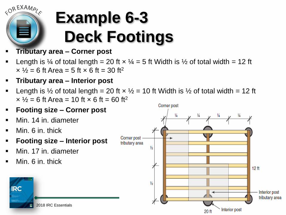
Example 6-3
Deck Footings Tributary area – Corner post
Length is ¼ of total length = 20 ft × ¼ = 5 ft Width is ½ of total width = 12 ft
× ½ = 6 ft Area = 5 ft × 6 ft = 30 ft2
Tributary area – Interior post
Length is ½ of total length = 20 ft × ½ = 10 ft Width is ½ of total width = 12 ft
× ½ = 6 ft Area = 10 ft × 6 ft = 60 ft2
Footing size – Corner post
Min. 14 in. diameter
Min. 6 in. thick
Footing size – Interior post
Min. 17 in. diameter
Min. 6 in. thick
2018 IRC Essentials Workbook Page 96-97
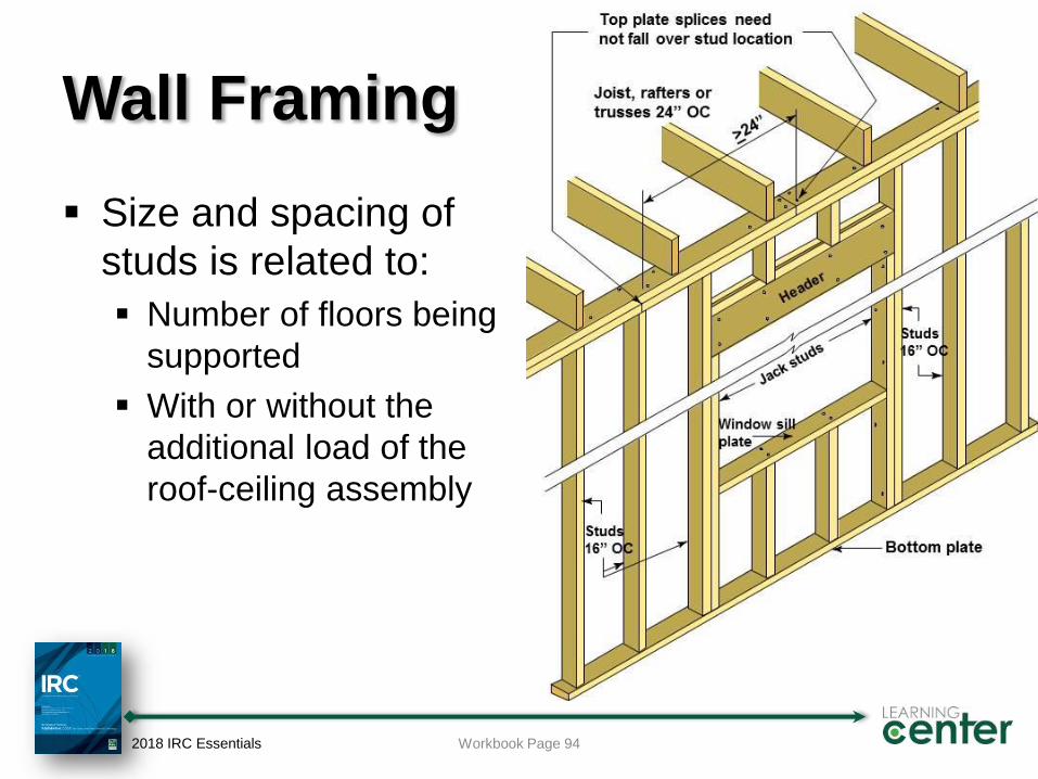
Wall Framing
Size and spacing of
studs is related to:
Number of floors being
supported
With or without the
additional load of the
roof-ceiling assembly
2018 IRC Essentials Workbook Page 94
Example 6-3
Stud Size and Spacing Determine the minimum size, maximum height
and maximum spacing of standard studs in an
exterior bearing wall
Given:
3 stories of wood framing (walk-out basement plus 2
stories)
Standard- or stud-grade lumber
2018 IRC Essentials Workbook Page 96-97

Example 6-3
Stud Size and Spacing Table R602.3(5)
Size, Height and Spacing of Wood Studs
2018 IRC Essentials
Stud
Size
(inches)
Bearing Walls Nonbearing Walls
Laterally
Unsupported
Stud Height
(feet)
Maximum
Spacing
When
Supporting a
Roof/Ceiling
Assembly or
a Habitable
Attic
Assembly
Only
Maximum
Spacing
When
Supporting
One Floor,
Plus a
Roof/Ceiling
Assembly or
a Habitable
Attic
Assembly
Maximum
Spacing
When
Supporting
Two Floors,
Plus a
Roof/Ceiling
Assembly or
a Habitable
Attic
Assembly
Maximum
Spacing
When
Supporting
One Floor
Only
Laterally
Unsupported
Stud Height
Maximum
Spacing
2 x 3 -- -- -- -- -- 10’ 16”
2 x 4 10 ft 24” 16” -- 24” 14’ 24”
3 x 4 10 ft 24” 24” 16” 24” 14’ 24”
2 x 5 10 ft 24” 24” -- 24” 16’ 24”
2 x 6 10 ft 24” 24” 16” 24” 20’ 24”
Workbook Page 96-97
Stud height in bearing
walls is generally limited to 10’
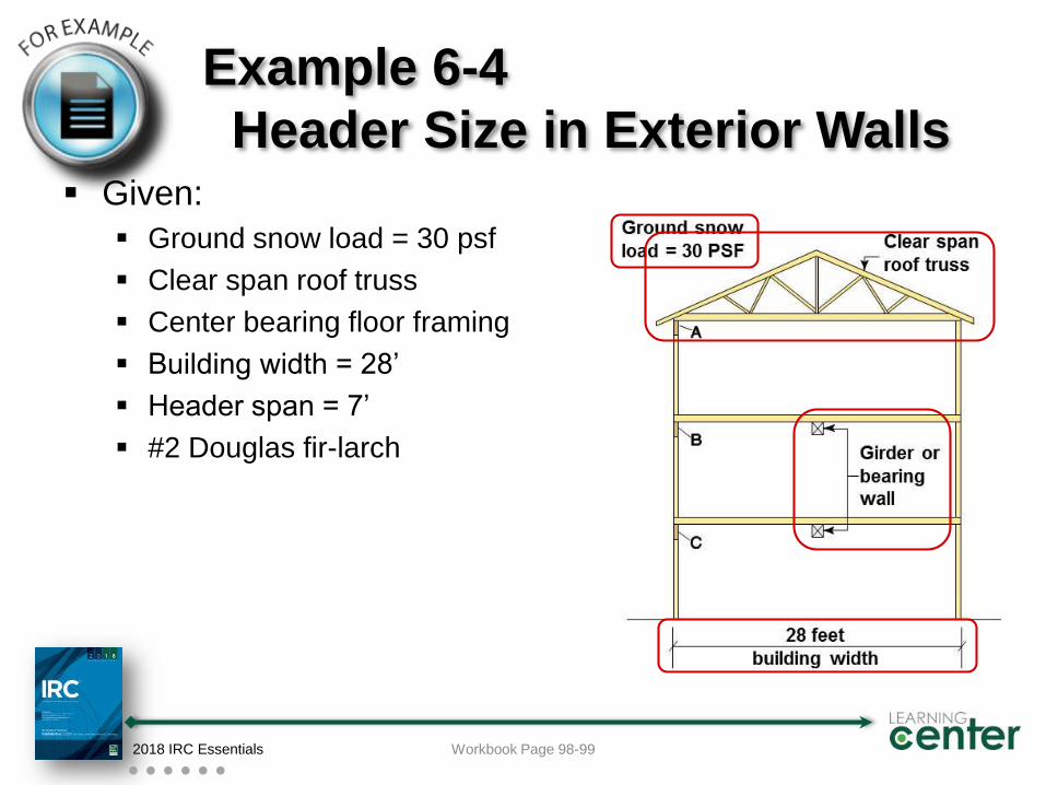
Example 6-4
Header Size in Exterior Walls Given:
Ground snow load = 30 psf
Clear span roof truss
Center bearing floor framing
Building width = 28’
Header span = 7’
#2 Douglas fir-larch
2018 IRC Essentials Workbook Page 98-99
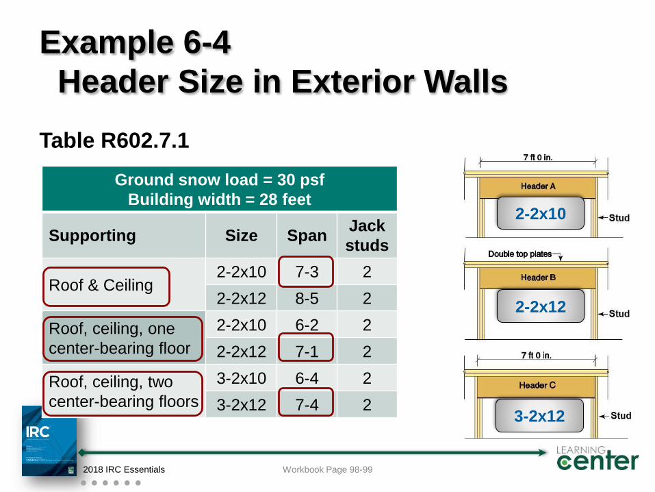
Example 6-4
Header Size in Exterior Walls
Table R602.7.1
Ground snow load = 30 psf
Building width = 28 feet
Supporting Size SpanJack
studs
Roof & Ceiling2-2x10 7-3 2
2-2x12 8-5 2
Roof, ceiling, one
center-bearing floor
2-2x10 6-2 2
2-2x12 7-1 2
Roof, ceiling, two
center-bearing floors
3-2x10 6-4 2
3-2x12 7-4 2
2018 IRC Essentials Workbook Page 98-99
2-2x10
2-2x12
3-2x12
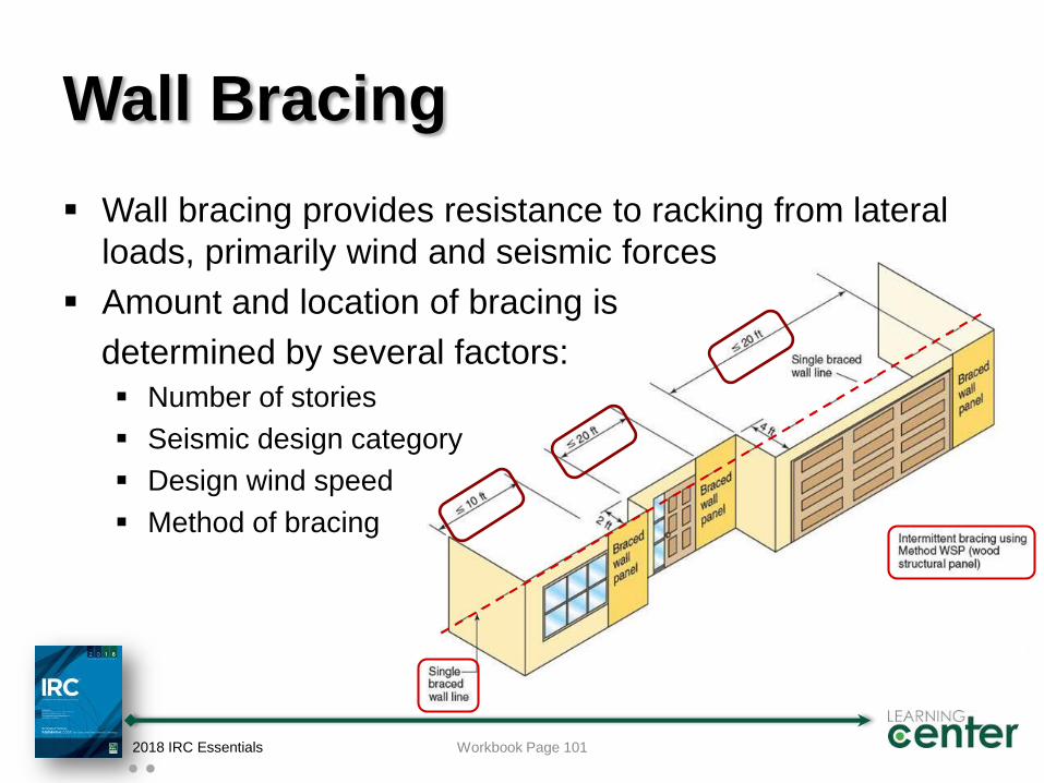
Wall Bracing
Wall bracing provides resistance to racking from lateral
loads, primarily wind and seismic forces
Amount and location of bracing is
determined by several factors:
Number of stories
Seismic design category
Design wind speed
Method of bracing
2018 IRC Essentials Workbook Page 101
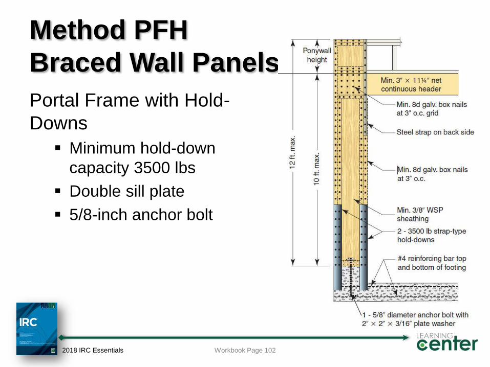
Method PFH
Braced Wall Panels
Portal Frame with Hold-
Downs
Minimum hold-down
capacity 3500 lbs
Double sill plate
5/8-inch anchor bolt
2018 IRC Essentials Workbook Page 102
Ceiling Joists
Ceiling joists
Support ceiling materials
Serve as rafter ties to resist the outward thrust of the
rafters at the top of the wall
Require adequate connection to the rafter and top of
wall
Ceiling joist spans for:
Attics without storage
Attics with limited storage
Attics with fixed stair access require joists sized as floor joists
2018 IRC Essentials Workbook Page 103
Rafters
Rafter spans based on:
Snow load of the geographic area;
Roof live load of 20 psf where snow load <30 psf;
Whether ceiling material is attached to the bottom of
the rafter
Connection to ceiling joists
Rafters are connected to the ceiling joists at the top
plate; or
2 x 4 rafter ties are required to resist the outward
thrust forces of the rafters on the wall
2018 IRC Essentials Workbook Page 103
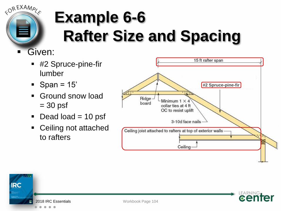
Example 6-6
Rafter Size and Spacing Given:
#2 Spruce-pine-fir
lumber
Span = 15’
Ground snow load
= 30 psf
Dead load = 10 psf
Ceiling not attached
to rafters
2018 IRC Essentials Workbook Page 104
#2 Spruce-pine-fir
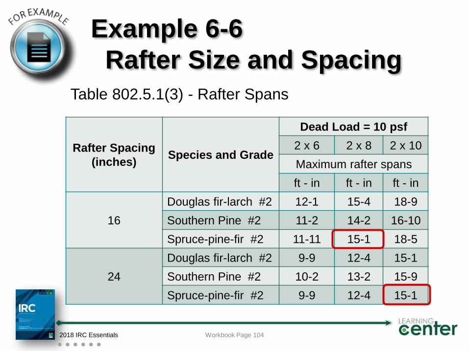
Example 6-6
Rafter Size and Spacing
Table 802.5.1(3) - Rafter Spans
2018 IRC Essentials Workbook Page 104
Rafter Spacing
(inches)Species and Grade
Dead Load = 10 psf
2 x 6 2 x 8 2 x 10
Maximum rafter spans
ft - in ft - in ft - in
16
Douglas fir-larch #2 12-1 15-4 18-9
Southern Pine #2 11-2 14-2 16-10
Spruce-pine-fir #2 11-11 15-1 18-5
24
Douglas fir-larch #2 9-9 12-4 15-1
Southern Pine #2 10-2 13-2 15-9
Spruce-pine-fir #2 9-9 12-4 15-1
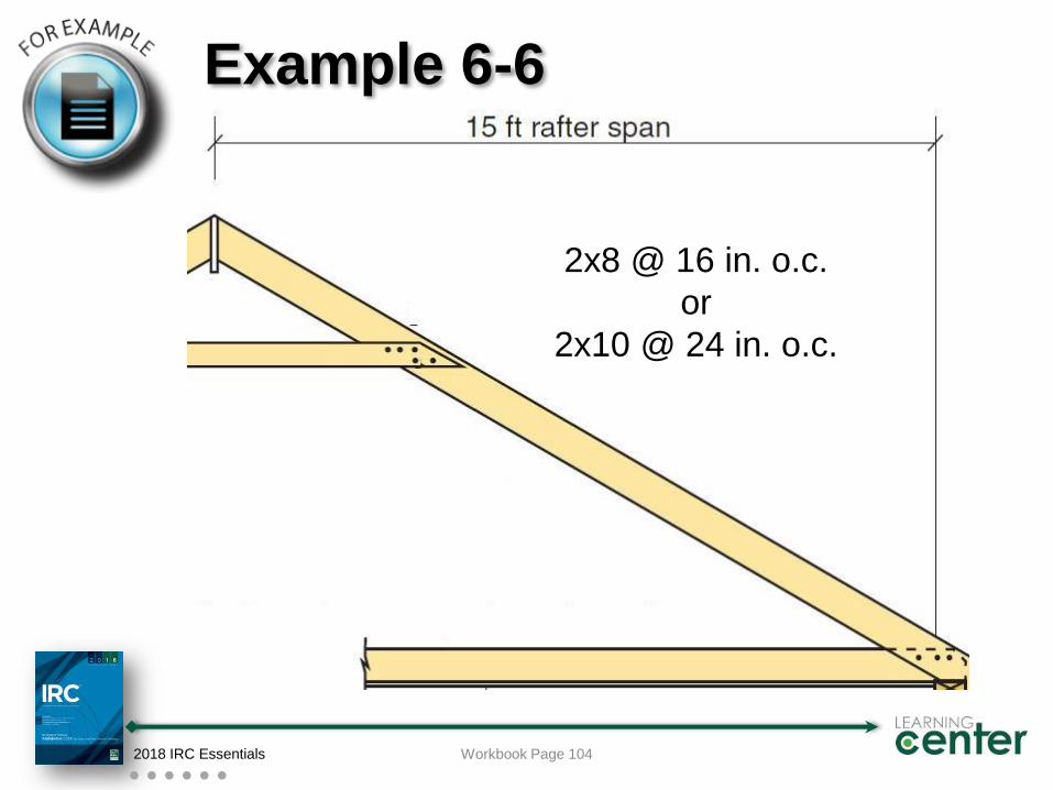
Example 6-6
Rafter Size and Spacing
2018 IRC Essentials Workbook Page 104
2x8 @ 16 in. o.c.
or
2x10 @ 24 in. o.c.
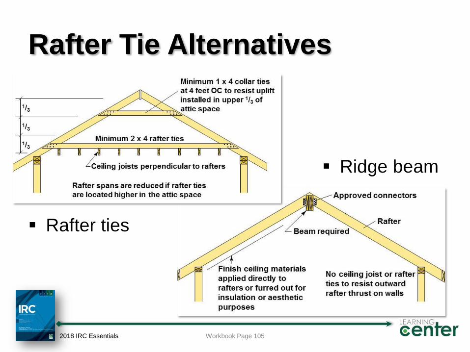
Rafter Tie Alternatives
Rafter ties
Ridge beam
2018 IRC Essentials Workbook Page 105
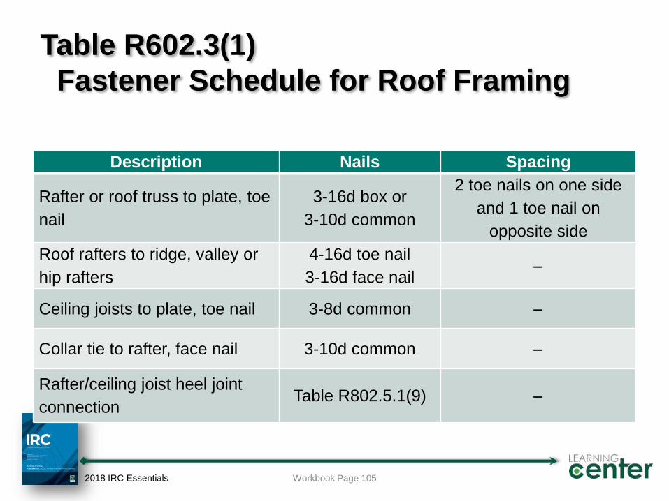
Table R602.3(1)
Fastener Schedule for Roof Framing
Description Nails Spacing
Rafter or roof truss to plate, toe
nail
3-16d box or
3-10d common
2 toe nails on one side
and 1 toe nail on
opposite side
Roof rafters to ridge, valley or
hip rafters
4-16d toe nail
3-16d face nail
Ceiling joists to plate, toe nail 3-8d common
Collar tie to rafter, face nail 3-10d common
Rafter/ceiling joist heel joint
connectionTable R802.5.1(9)
2018 IRC Essentials Workbook Page 105
Roof Uplift Connections
Table provides uplift values based on:
Building width
Wind speed
Exposure category
Roof pitch
For ≤200 lbs. uplift, toe-nail connection is OK
For >200 lbs. uplift, a connector is required
2018 IRC Essentials Workbook Page 106
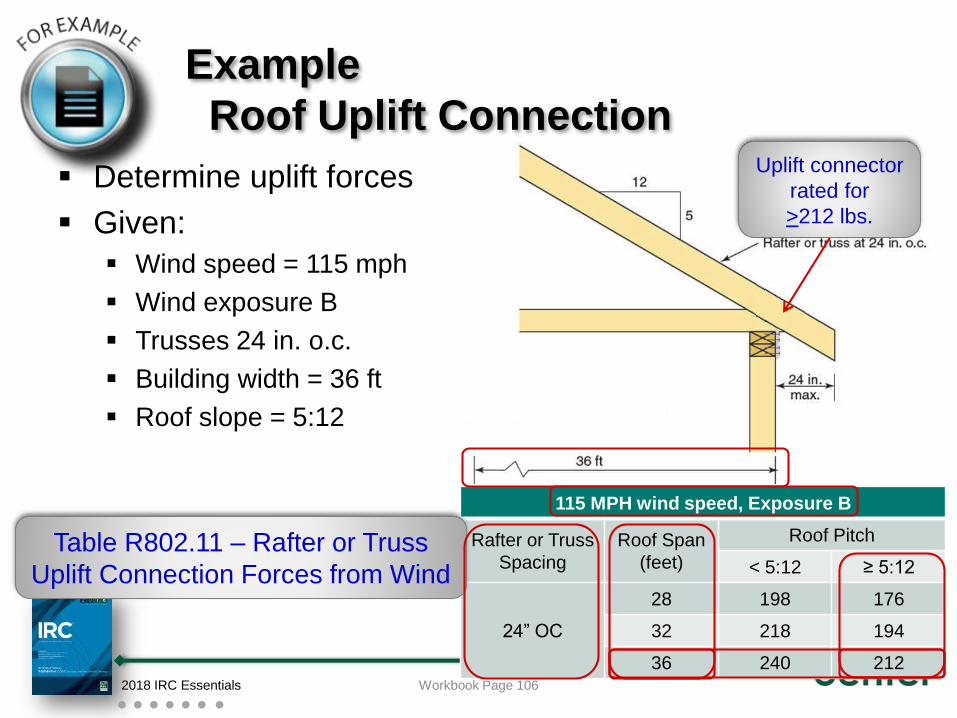
Example
Roof Uplift Connection
Determine uplift forces
Given:
Wind speed = 115 mph
Wind exposure B
Trusses 24 in. o.c.
Building width = 36 ft
Roof slope = 5:12
2018 IRC Essentials Workbook Page 106
115 MPH wind speed, Exposure B
Rafter or Truss
Spacing
Roof Span
(feet)
Roof Pitch
< 5:12 ≥ 5:12
24” OC
28 198 176
32 218 194
36 240 212
Table R802.11 – Rafter or Truss
Uplift Connection Forces from Wind
Uplift connector
rated for
>212 lbs.
Attic Ventilation and Access
Total net free ventilating area must be 1/150 of attic area
Reduced to 1/300 when 40% to 50% of ventilating area in upper
portion of space
Unvented attics may be permitted with certain conditions
Access to attics required when:
Attic area >30 ft2, and
Attic height >30”
Access
Minimum 22” x 30”
30” headroom above the opening
Located in a hallway or other readily accessible location
2018 IRC Essentials Workbook Page 107

Finishes and Weather
Protection
Part IV
Interior Finishes
Minimum installation requirements for:
Gypsum board (drywall)
Plaster
Ceramic tile
Wood paneling
Inspection is not required except when part of a
fire-resistance-rated assembly
2018 IRC Essentials Workbook Page 111
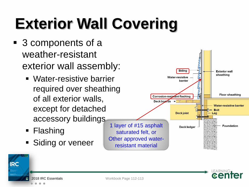
Exterior Wall Covering 3 components of a
weather-resistant
exterior wall assembly:
Water-resistive barrier
required over sheathing
of all exterior walls,
except for detached
accessory buildings
Flashing
Siding or veneer
2018 IRC Essentials Workbook Page 112-113
1 layer of #15 asphalt
saturated felt, or
Other approved water-
resistant material
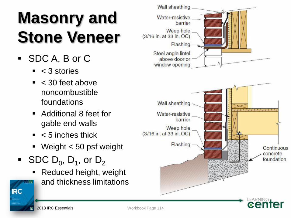
Masonry and
Stone Veneer
SDC A, B or C
< 3 stories
< 30 feet above
noncombustible
foundations
Additional 8 feet for
gable end walls
< 5 inches thick
Weight < 50 psf weight
SDC D0, D1, or D2
Reduced height, weight
and thickness limitations
2018 IRC Essentials Workbook Page 114
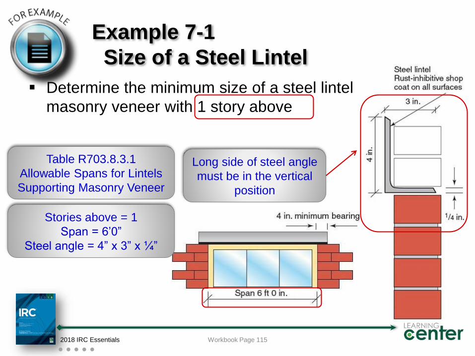
Example 7-1
Size of a Steel Lintel
Determine the minimum size of a steel lintel supporting
masonry veneer with 1 story above
2018 IRC Essentials Workbook Page 115
Stories above = 1
Span = 6’0”
Steel angle = 4” x 3” x ¼”
Table R703.8.3.1
Allowable Spans for Lintels
Supporting Masonry Veneer
Long side of steel angle
must be in the vertical
position
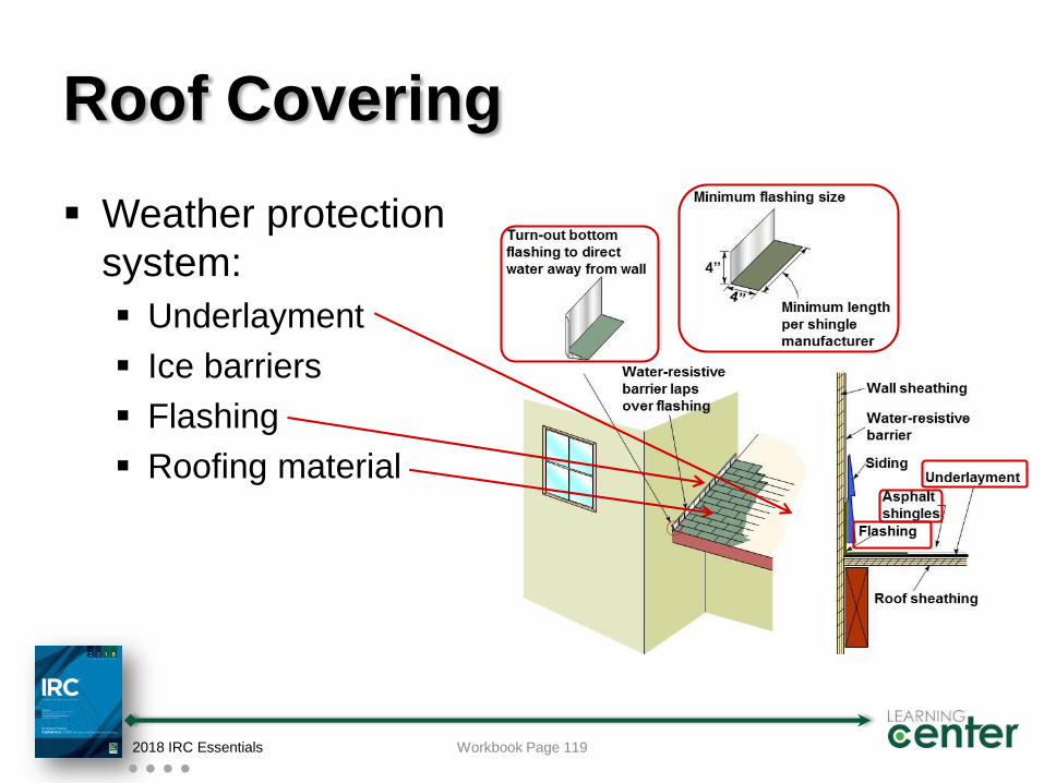
Roof Covering
Weather protection
system:
Underlayment
Ice barriers
Flashing
Roofing material
2018 IRC Essentials Workbook Page 119
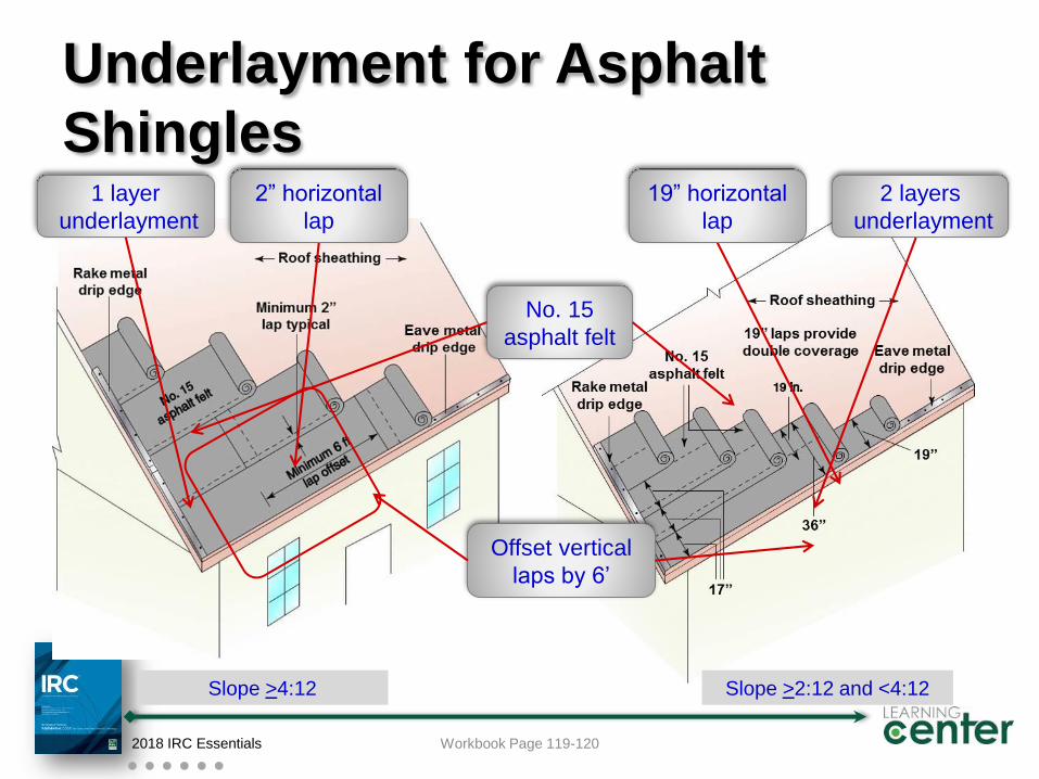
Underlayment for Asphalt
Shingles
2018 IRC Essentials
Slope >2:12 and <4:12
Workbook Page 119-120
Slope >4:12
2 layers
underlayment
1 layer
underlayment
19” horizontal
lap
2” horizontal
lap
No. 15
asphalt felt
Offset vertical
laps by 6’
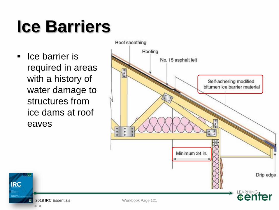
Ice Barriers
Ice barrier is
required in areas
with a history of
water damage to
structures from
ice dams at roof
eaves
2018 IRC Essentials Workbook Page 121

2018 IRC Essentials
Discussion Activity
Final Reflection
This slide will help the learner to reflect on the day
and what they will take back to the job and apply.
What? What happened and what was observed
in the training?
So what? What did you learn? What difference
did this training make?
Now what? How will you do things differently
back on the job as a result of this training?
2018 IRC Essentials
International Code Council is a Registered Provider with The American
Institute of Architects Continuing Education Systems. Credit earned on
completion of this program will be reported to CES Records for AIA
members. Certificates of Completion for non-AIA members are available on
request.
This program is registered with the AIA/CES for continuing professional
education. As such, it does not include content that may be deemed or
construed to be an approval or endorsement by the AIA of any material of
construction or any method or manner of handling, using, distributing, or
dealing in any material or product. Questions related to specific materials,
methods, and services will be addressed at the conclusion of this
presentation.
Copyright Materials
This presentation is protected by US and International
Copyright laws. Reproduction, distribution, display and use of
the presentation without written permission of the speaker is
prohibited.
© International Code Council 2018
Thank you for participating
To schedule a seminar, contact:
The ICC Training & Education Department
1-888-ICC-SAFE (422-7233) Ext. 33821
or
E-mail: [email protected]
2018 IRC Essentials