Embed Size (px)
Citation preview

Session 12
STEPS 3 AND 4
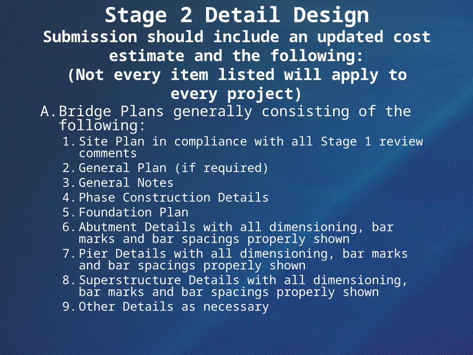
Stage 2 Detail DesignSubmission should include an updated cost
estimate and the following:(Not every item listed will apply to every project)
A. Bridge Plans generally consisting of the following:1. Site Plan in compliance with all Stage 1 review comments2. General Plan (if required)3. General Notes4. Phase Construction Details5. Foundation Plan6. Abutment Details with all dimensioning, bar marks and bar
spacings properly shown7. Pier Details with all dimensioning, bar marks and bar
spacings properly shown8. Superstructure Details with all dimensioning, bar marks and
bar spacings properly shown9. Other Details as necessary
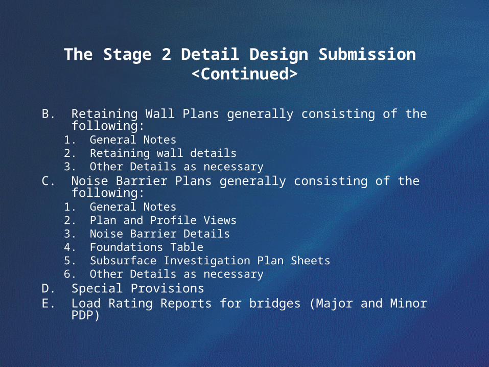
The Stage 2 Detail Design Submission <Continued>
B. Retaining Wall Plans generally consisting of the following:1. General Notes2. Retaining wall details3. Other Details as necessary
C. Noise Barrier Plans generally consisting of the following:1. General Notes2. Plan and Profile Views3. Noise Barrier Details4. Foundations Table5. Subsurface Investigation Plan Sheets6. Other Details as necessary
D. Special ProvisionsE. Load Rating Reports for bridges (Major and Minor PDP)
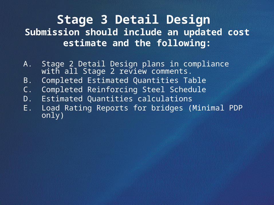
Stage 3 Detail Design Submission should include an updated cost
estimate and the following:
A. Stage 2 Detail Design plans in compliance with all Stage 2 review comments.
B. Completed Estimated Quantities TableC. Completed Reinforcing Steel ScheduleD. Estimated Quantities calculationsE. Load Rating Reports for bridges (Minimal PDP only)
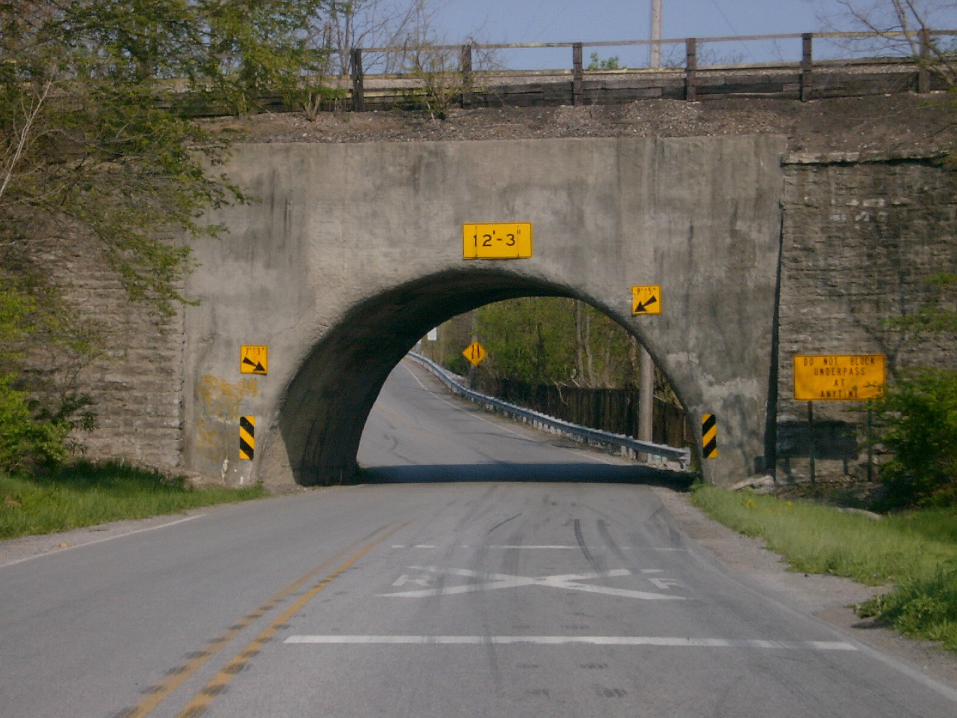

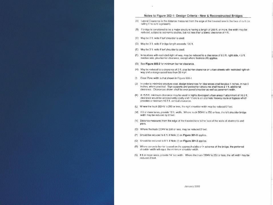
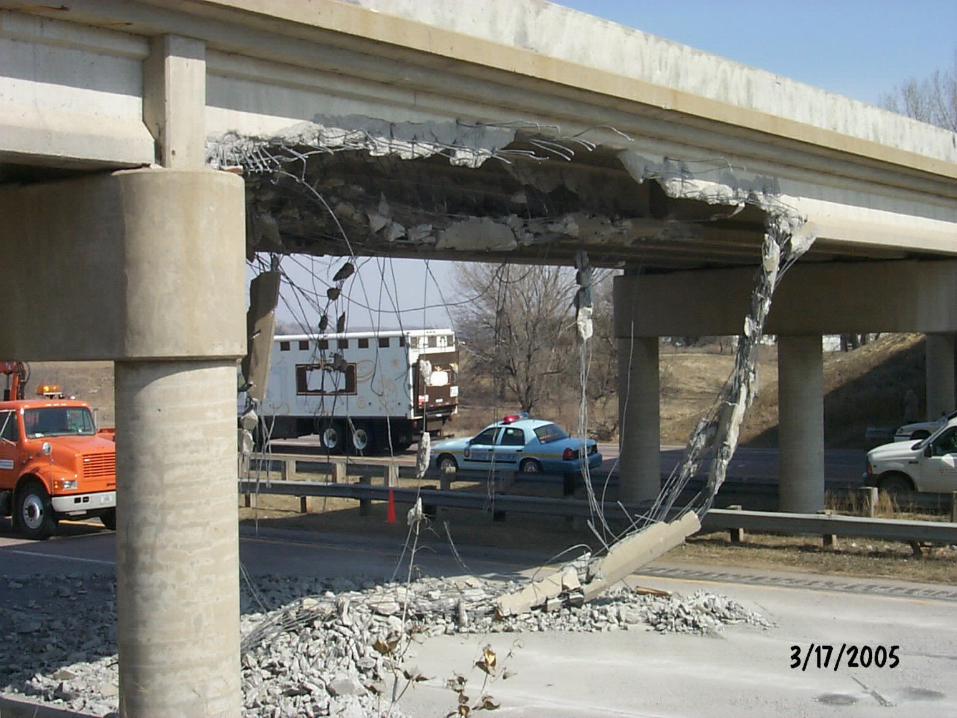
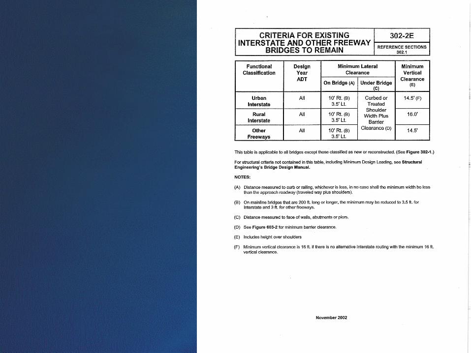
Item 65 Vertical Clearance Interstates, freeways, expressways & arterial
Minimum clearance 16.5’
Collectors & Local Minimum clearance 14.5’
REQUIRED AT ALL POINTS LESS THAN
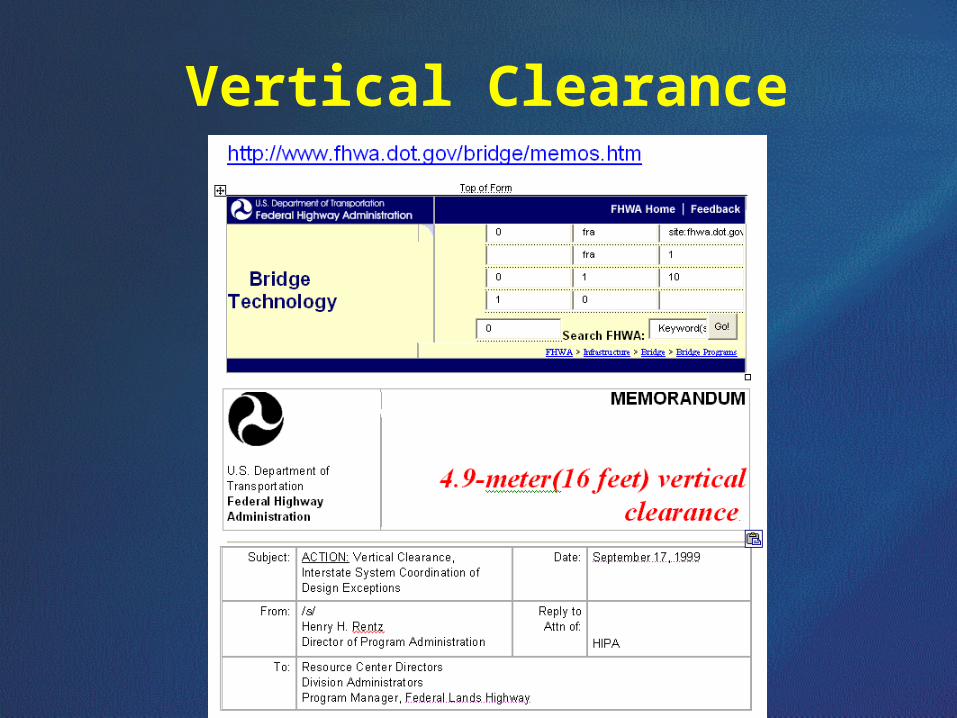
Vertical Clearance
L & D Manual
Vertical & Horizontal Clearance
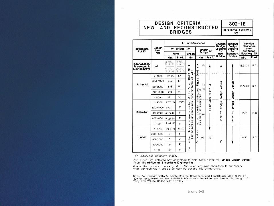

17’ required
Inspection
Sufficiency Ratings
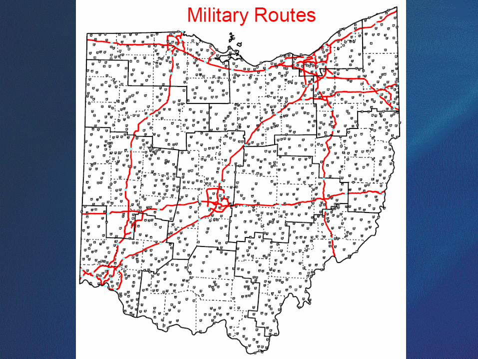
LOADING REQUIREMENTS
• All bridge structures shall be designed for an HS25 loading or the alternate military loading, whichever produces the greatest stresses and live load deflections, unless otherwise stated in this manual. Figure 301 illustrates the HS25 truck and lane loadings.
• All bridges shall be designed for a future wearing surface (FWS) of 60 psf .
• All steel structures shall be designated as Case I or Case II as defined by AASHTO for fatigue design.
• Bridge structures on LPA projects shall be designed to the same loading requirements as traditionally funded projects except an HS20-44 loading may be used in lieu of the HS25 ] loading.
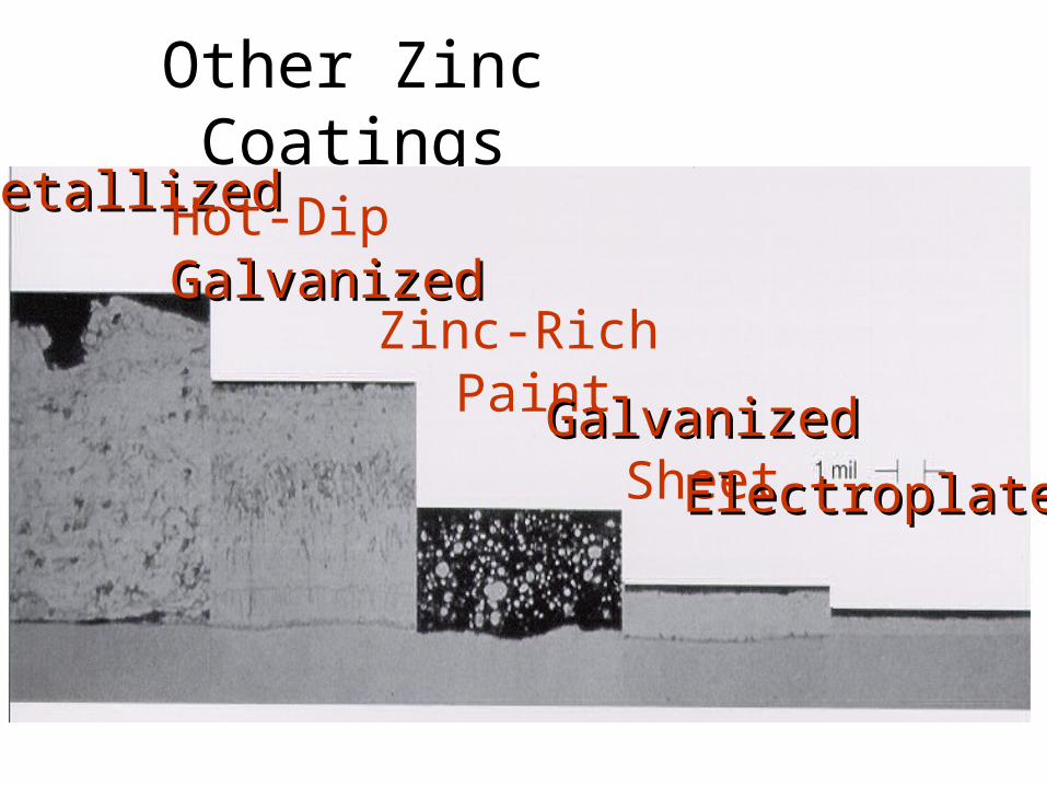
Other Zinc CoatingsMetallizedMetallizedHot-Dip
GalvanizedGalvanizedZinc-Rich
PaintGalvanizedGalvanizedSheetElectroplatedElectroplated
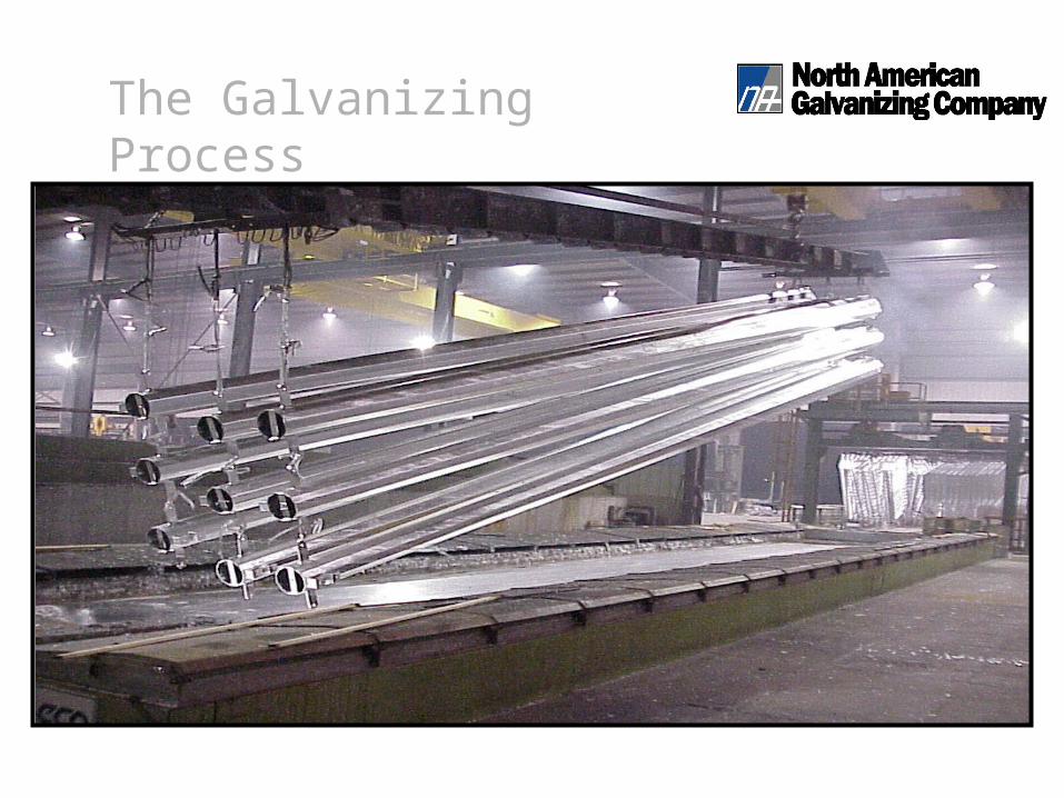
The Galvanizing Process


![[5145]-11 - collegecirculars.unipune.ac.incollegecirculars.unipune.ac.in/sites/examdocs/April 2017/B...Explain in detail various methods used to estimate absorption rate ... Explain](https://img.pdfslide.us/doc/110x75/5b3f30277f8b9aff118bd277/5145-11-2017bexplain-in-detail-various-methods-used-to-estimate-absorption.jpg)