Embed Size (px)
Citation preview

Visit us on the web:
www.servo-repair.com www.servorepair.ca
www.ferrocontrol.com www.sandvikrepair.com
www.accuelectric.com
For 24/7 repair services :
USA: 1 (888) 932 - 9183 Canada: 1 (905) 829 -2505
Emergency After hours: 1 (416) 624 0386
Servicing USA and Canada
Scroll down to view your document!
Over 100 years cumulative experience
24 hour rush turnaround / technical support service
Established in 1993
The leading independent repairer of servo motors and drives in North America.
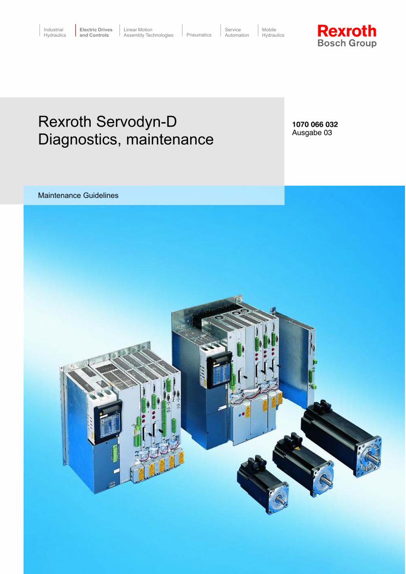
Rexroth Servodyn�DDiagnostics, maintenance
MobileHydraulics
ServiceAutomationPneumatics
Linear MotionAssembly Technologies
Electric Drivesand Controls
IndustrialHydraulics
Maintenance Guidelines
1070 066 032 Ausgabe 03
II Electric Drivesand Controls
Bosch Rexroth AG Servodyn-D 1070 066 032 / 03
Rexroth Servodyn-DDiagnostics, maintenance
Maintenance Guidelines
DOK-SERV*D-DIAGNOSTICS-WA03-EN-P
The present manual informs you about the diagnostics options of theServodyn-D drive series.
Description ReleaseDate
Notes
DOK-SERV*D-DIAGNOSTICS-WA03-EN-P 07.2003 Softwarereleases referto page 1�10
E Bosch Rexroth AG, 1998 � 2003
Copying this document, giving it to others and the use orcommunication of the contents thereof without express authority, areforbidden. Offenders are liable for the payment of damages. All rightsare reserved in the event of the grant of a patent or the registrationof a utility model or design (DIN 34�1).
The specified data is for product description purposes only andmay not be deemed to be guaranteed unless expressly confirmedin the contract. All rights are reserved with respect to the contentof this documentation and the availability of the product.
Bosch Rexroth AGPostfach 11 62D-64701 ErbachBerliner Straße 25D-64711 ErbachTel.: +49 (0) 60 62/78-0Fax: +49 (0) 60 62/78-4 28Abt.: BRC/ESM11 (WE)
Title
Type of Documentation
Document Typecode
Purpose of Documentation
Record of Revisions
Copyright
Validity
Published by
Electric Drivesand Controls
IIIBosch Rexroth AGServodyn-D1070 066 032 / 03
Contents
ContentsPage
1 Safety Instructions 1�1 . . . . . . . . . . . . . . . . . . . . . . . 1.1 Intended use 1�1 . . . . . . . . . . . . . . . . . . . . . . . . . . . . . . . . . . . . . . . . 1.2 Qualified personnel 1�3 . . . . . . . . . . . . . . . . . . . . . . . . . . . . . . . . . . 1.3 Safety markings on products 1�4 . . . . . . . . . . . . . . . . . . . . . . . . . . 1.4 Safety instructions in this manual 1�5 . . . . . . . . . . . . . . . . . . . . . . 1.5 Safety instructions for the described product 1�6 . . . . . . . . . . . . 1.6 Documentation, software release and trademarks 1�9 . . . . . . .
2 Mains connection at the place of installation 2�1 2.1 Earthing 2�1 . . . . . . . . . . . . . . . . . . . . . . . . . . . . . . . . . . . . . . . . . . . . 2.2 Earth-leakage circuit-breaker 2�3 . . . . . . . . . . . . . . . . . . . . . . . . .
3 Marks, certifications 3�1 . . . . . . . . . . . . . . . . . . . . . . 3.1 CE-marking 3�1 . . . . . . . . . . . . . . . . . . . . . . . . . . . . . . . . . . . . . . . . . 3.2 EU design type certification 3�2 . . . . . . . . . . . . . . . . . . . . . . . . . . . 3.3 UL/CSA certification 3�3 . . . . . . . . . . . . . . . . . . . . . . . . . . . . . . . . .
4 Diagnostics displays at the drive 4�1 . . . . . . . . . . 4.1 VMA..KB, VMA..KE status, warning and error displays 4�1 . . . 4.2 VMA..KR, VMA..B,C,D,F status displays 4�2 . . . . . . . . . . . . . . . 4.3 VMA..KR, VMA..B,C,D,F warning displays 4�3 . . . . . . . . . . . . . . 4.4 Status displays DM and DS (without frequency inverter) 4�4 . . 4.5 VMA..KR, VMA..B,C,D,F and DM/DS error displays
(without frequency inverter) 4�5 . . . . . . . . . . . . . . . . . . . . . . . . . . . 4.5.1 List of error number in parameter P-0-0095 4�14 . . . . . . . . . . . 4.6 PROFIBUS-DP errors 4�28 . . . . . . . . . . . . . . . . . . . . . . . . . . . . . . . . 4.7 DMA computer errors (without SERCOS interface) 4�28 . . . . . . 4.8 Servodyn-D frequency inverter displays 4�29 . . . . . . . . . . . . . . . . 4.8.1 Status/warning displays 4�29 . . . . . . . . . . . . . . . . . . . . . . . . . . . . . 4.8.2 Error displays 4�31 . . . . . . . . . . . . . . . . . . . . . . . . . . . . . . . . . . . . .
5 Connection overview 5�1 . . . . . . . . . . . . . . . . . . . . . 5.1 VMA..KB, VMA..KE supply module
(with ballast switch) 5�1 . . . . . . . . . . . . . . . . . . . . . . . . . . . . . . . . . . 5.2 VMA..KR, VMA..B,C,D,F supply module
(with current regeneration) 5�2 . . . . . . . . . . . . . . . . . . . . . . . . . . . . 5.3 DMA module with analog interface or
positioning function (MC) 5�3 . . . . . . . . . . . . . . . . . . . . . . . . . . . . . 5.4 DMA module with SERCOS interface 5�4 . . . . . . . . . . . . . . . . . . 5.5 DMA module with CAN bus 5�5 . . . . . . . . . . . . . . . . . . . . . . . . . . . 5.6 DMA module with PROFIBUS-DP 5�6 . . . . . . . . . . . . . . . . . . . . . 5.7 DM..8001-D frequency inverter with analog interface 5�7 . . . . . 5.8 Stand-alone module DS, supply unit 5�8 . . . . . . . . . . . . . . . . . . . 5.8.1 Overview of DS..K xxx2-D (in set�up mode) 5�8 . . . . . . . . . . .
IV Electric Drivesand Controls
Bosch Rexroth AG Servodyn-D 1070 066 032 / 03
Contents
5.9 Overview of DS..K xxx1-D 5�9 . . . . . . . . . . . . . . . . . . . . . . . . . . . .
6 Replacing components 6�1 . . . . . . . . . . . . . . . . . . . 6.1 Motors 6�1 . . . . . . . . . . . . . . . . . . . . . . . . . . . . . . . . . . . . . . . . . . . . . 6.2 Drive modules 6�3 . . . . . . . . . . . . . . . . . . . . . . . . . . . . . . . . . . . . . . 6.2.1 VM...K and DM...K 6�3 . . . . . . . . . . . . . . . . . . . . . . . . . . . . . . . . . 6.2.2 DC link connection of VMA..B,C,D and DMA..A,B,D
with backplane modules 6�4 . . . . . . . . . . . . . . . . . . . . . . . . . . . . 6.2.3 DC link connection of VMW..F and DMW..F
with water cooling 6�5 . . . . . . . . . . . . . . . . . . . . . . . . . . . . . . . . . .
A Annex A�1 . . . . . . . . . . . . . . . . . . . . . . . . . . . . . . . . . . . A.1 Index A�1 . . . . . . . . . . . . . . . . . . . . . . . . . . . . . . . . . . . . . . . . . . . . . .
Electric Drivesand Controls
1�1Bosch Rexroth AGServodyn-D1070 066 032 / 03
Safety Instructions
1 Safety Instructions
Please read this manual before commissioning the Servodyn-D drives.Store this manual in a place to which all users have access at any time.
1.1 Intended use
This manual contains information required for the intended use of thisproduct.
The described low-voltage motors are intended for use in commercialor industrial systems. They comply with the harmonized standards ofthe VDE 0530/EN 60034 series. Their use in potentially explosive atmo-spheres is not admissible unless expressly permitted by additionalinstructions.
Air-cooled designs are rated for ambient temperatures ranging between�20 to +40 _C, and an operating altitude of � 1000 m above sea level.Rating plate specifications deviating from this standard must be strictlyobserved. Conditions at the operating site must correspond to all specifi-cations stated on the rating plate.
Low-voltage motors comprise components intended for integration intomachines as contemplated by the EU Declaration of Conformity, as de-fined by Machinery Directive (98/37/EC, 98/79/EC). Before putting themotors into operation, ensure that the machine the motors are to beinstalled in meets the stipulations of the Machinery Directive (note alsoEN 60204-1).
The drive inverters describedD have been developed, manufactured, tested and documented in
compliance with the safety standards. These products normally poseno danger to persons or property if they are used in accordance withthe handling stipulations and safety notes prescribed for their config-uration, mounting, and proper operation.
D comply with the requirements ofD the EMC Directives (89/336/EEC, 93/68/EEC and 93/44/EEC)D the EMC product standard EN 61800-3 + A11D the Low-Voltage Directive (73/23/EEC)D the harmonized standards EN 50178 (VDE 0160) and
EN 60146-1-1 (VDE 0558-11)D are designed for operation in industrial environments, i.e.
D no direct connection to public low-voltage power supply,D connection to the medium- or high-voltage system via a trans-
former.In residential environments, in trade and commerce as well as smallenterprises class A equipment may only be used if the following warn-ing is attached:

1�2 Electric Drivesand Controls
Bosch Rexroth AG Servodyn-D 1070 066 032 / 03
Safety Instructions
. This is a Class A device. In a residential area, this device may causeradio interference. In such case, the user may be required tointroduce suitable countermeasures, and to bear the cost of thesame.
Before putting the drive inverters into operation, ensure that the machinewhich the inverters are to be installed in meets the stipulations of the Ma-chinery Directive (98/37/EC, 98/79/EC) and the EMC Directive(89/336/EEC).
The faultless, safe functioning of the product requires proper transport,storage, erection and installation as well as careful operation.
Electric Drivesand Controls
1�3Bosch Rexroth AGServodyn-D1070 066 032 / 03
Safety Instructions
1.2 Qualified personnel
The requirements as to qualified personnel depend on the qualificationprofiles described by ZVEI (central association of the electrical industry)and VDMA (association of German machine and plant builders) in:Weiterbildung in der Automatisierungstechnikedited by: ZVEI and VDMAMaschinenbauVerlagPostfach 71 08 64D-60498 Frankfurt.
The present manual is designed for drive specialists.
Programming, start and operation as well as the modification of programparameters is reserved to properly trained personnel! This personnelmust be able to judge potential hazards arising from programming, pro-gram changes and in general from the mechanical, electrical, or elec-tronic equipment.
Interventions in the hardware and software of our products, unless de-scribed otherwise in this manual, are reserved to specialized Rexrothpersonnel.
Tampering with the hardware or software, ignoring warning signs at-tached to the components, or non-compliance with the warning notesgiven in this manual may result in serious bodily injury or damage toproperty.
Only electrotechnicians as recognized under IEV 826-09-01 (modified)who are familiar with the contents of this manual may install and servicethe products described.
Such personnel areD those who, being well trained and experienced in their field and famil-
iar with the relevant norms, are able to analyze the jobs being carriedout and recognize any hazards which may have arisen.
D those who have acquired the same amount of expert knowledgethrough years of experience that would normally be acquired throughformal technical training.
With regard to the foregoing, please note our comprehensive range oftraining courses. Please visit our website at http://www.boschrexroth.com for the latest information concerning training courses, teachware andtraining systems. Personal information is available from our DidacticCenter Erbach,Telephone: (+49) (0) 60 62 78-600.
1�4 Electric Drivesand Controls
Bosch Rexroth AG Servodyn-D 1070 066 032 / 03
Safety Instructions
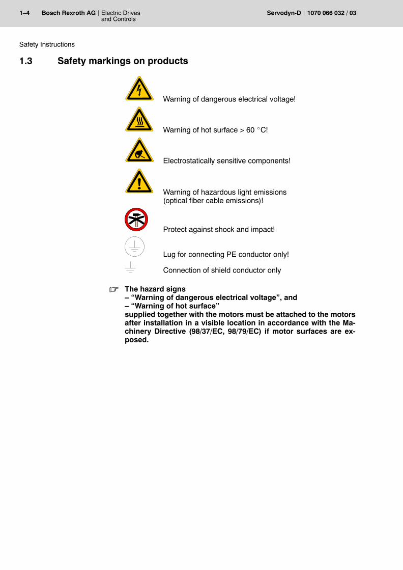
1.3 Safety markings on products
Warning of dangerous electrical voltage!
Warning of hot surface > 60 _C!
Electrostatically sensitive components!
Warning of hazardous light emissions (optical fiber cable emissions)!
Protect against shock and impact!
Lug for connecting PE conductor only!
Connection of shield conductor only
. The hazard signs� �Warning of dangerous electrical voltage�, and� �Warning of hot surface�supplied together with the motors must be attached to the motorsafter installation in a visible location in accordance with the Ma-chinery Directive (98/37/EC, 98/79/EC) if motor surfaces are ex-posed.
Electric Drivesand Controls
1�5Bosch Rexroth AGServodyn-D1070 066 032 / 03
Safety Instructions
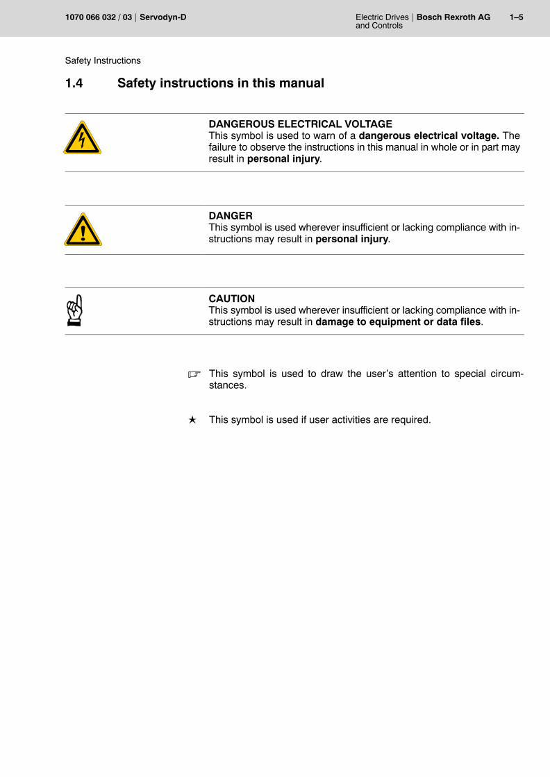
1.4 Safety instructions in this manual
DANGEROUS ELECTRICAL VOLTAGEThis symbol is used to warn of a dangerous electrical voltage. Thefailure to observe the instructions in this manual in whole or in part mayresult in personal injury.
DANGERThis symbol is used wherever insufficient or lacking compliance with in-structions may result in personal injury.
CAUTIONThis symbol is used wherever insufficient or lacking compliance with in-structions may result in damage to equipment or data files.
. This symbol is used to draw the user�s attention to special circum-stances.
L This symbol is used if user activities are required.
1�6 Electric Drivesand Controls
Bosch Rexroth AG Servodyn-D 1070 066 032 / 03
Safety Instructions
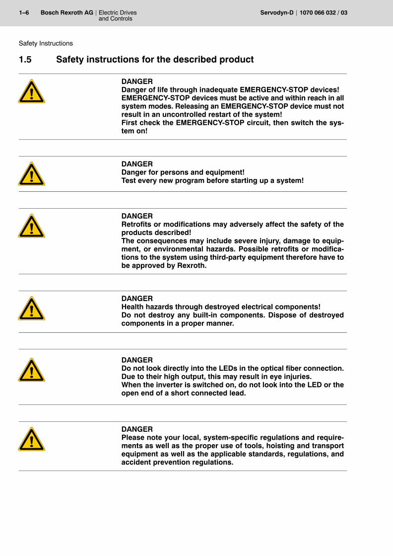
1.5 Safety instructions for the described product
DANGERDanger of life through inadequate EMERGENCY-STOP devices!EMERGENCY-STOP devices must be active and within reach in allsystem modes. Releasing an EMERGENCY-STOP device must notresult in an uncontrolled restart of the system! First check the EMERGENCY-STOP circuit, then switch the sys-tem on!
DANGERDanger for persons and equipment!Test every new program before starting up a system!
DANGERRetrofits or modifications may adversely affect the safety of theproducts described!The consequences may include severe injury, damage to equip-ment, or environmental hazards. Possible retrofits or modifica-tions to the system using third-party equipment therefore have tobe approved by Rexroth.
DANGERHealth hazards through destroyed electrical components!Do not destroy any built-in components. Dispose of destroyedcomponents in a proper manner.
DANGERDo not look directly into the LEDs in the optical fiber connection.Due to their high output, this may result in eye injuries.When the inverter is switched on, do not look into the LED or theopen end of a short connected lead.
DANGERPlease note your local, system-specific regulations and require-ments as well as the proper use of tools, hoisting and transportequipment as well as the applicable standards, regulations, andaccident prevention regulations.
Electric Drivesand Controls
1�7Bosch Rexroth AGServodyn-D1070 066 032 / 03
Safety Instructions
DANGEROUS ELECTRICAL VOLTAGEUnless described otherwise, maintenance works must be per-formed on inactive systems! The system must be protectedagainst unauthorized or accidental reclosing.
Measuring or test activities on the live system are reserved toqualified electrical personnel!
DANGEROUS ELECTRICAL VOLTAGELethal voltages of up to 375 V DC against ground on all power con-nections and DC link connections!
The drives must not be switched on unless all covers have beenfitted! When the drive has been disconnected from mains, wait forup to 5 minutes until the system is de-energized before removingany covers.
The drive must always be examined for safe isolation from supply!
DANGER � WARNING OF HOT SURFACE!The surfaces of motors can reach temperatures of up to approx.100 _C.A touch guard is to be provided where necessary.
CAUTIONImpacts and shocks applied to the shaft end will damage the rotaryencoder and ball bearings!Drive elements such as pulleys, clutch disks, toothed wheels etc.may only be assembled or removed by continuously heating upthe drive elements or with a suitable installation or removal tool.Use the thread in the shaft end.
CAUTIONuse only spare parts approved by Rexroth!
CAUTIONDamages to the module or inverter by removing plug-in connec-tions.All plug-in connections to the encoder may only be inserted or re-moved while the drive is switched off.
1�8 Electric Drivesand Controls
Bosch Rexroth AG Servodyn-D 1070 066 032 / 03
Safety Instructions
CAUTIONObserve all precautions for ESD protection when handling mod-ules and components! Avoid electrostatic discharge!
The following protective measures must be observed for modules andcomponents sensitive to electrostatic discharge (ESD)!D Personnel responsible for storage, transport, and handling must have
training in ESD protection.D ESD-sensitive components must be stored and transported in the
prescribed protective packaging.D ESD-sensitive components may only be handled at special ESD-
workplaces.D Personnel, working surfaces, as well as all equipment and tools
which may come into contact with ESD-sensitive components musthave the same potential (e.g. by grounding).
D Wear an approved grounding bracelet. The grounding bracelet mustbe connected with the working surface through a cable with an inte-grated 1 MW resistor.
D ESD-sensitive components may by no means come into contact withchargeable objects, including most plastic materials.
D When ESD-sensitive components are installed in or removed fromequipment, the equipment must be de-energized.
Electric Drivesand Controls
1�9Bosch Rexroth AGServodyn-D1070 066 032 / 03
Safety Instructions
1.6 Documentation, software release and trademarks
Documentation
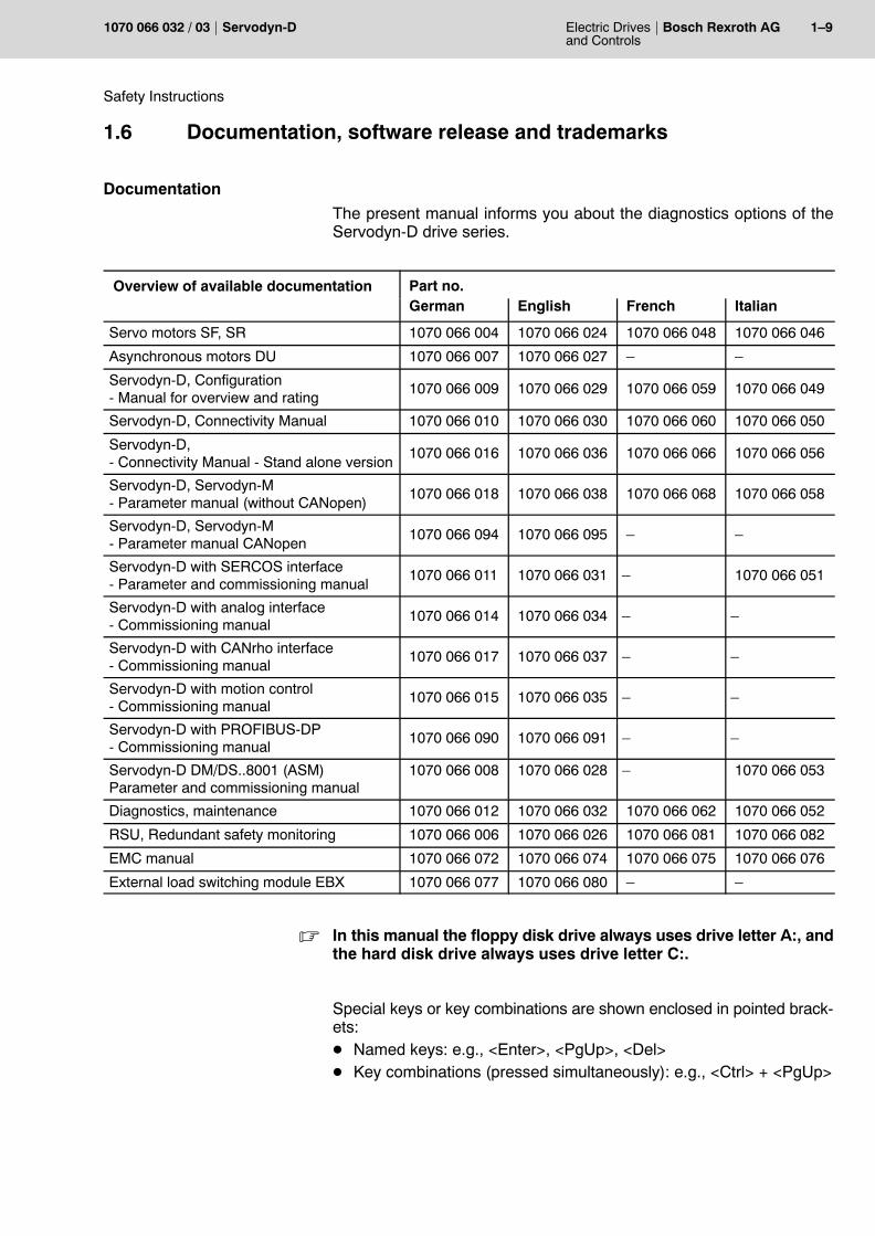
The present manual informs you about the diagnostics options of theServodyn-D drive series.
Overview of available documentation Part no.German English French Italian
Servo motors SF, SR 1070 066 004 1070 066 024 1070 066 048 1070 066 046
Asynchronous motors DU 1070 066 007 1070 066 027 � �
Servodyn-D, Configuration- Manual for overview and rating
1070 066 009 1070 066 029 1070 066 059 1070 066 049
Servodyn-D, Connectivity Manual 1070 066 010 1070 066 030 1070 066 060 1070 066 050
Servodyn-D, - Connectivity Manual - Stand alone version
1070 066 016 1070 066 036 1070 066 066 1070 066 056
Servodyn-D, Servodyn-M- Parameter manual (without CANopen)
1070 066 018 1070 066 038 1070 066 068 1070 066 058
Servodyn-D, Servodyn-M- Parameter manual CANopen
1070 066 094 1070 066 095 � �
Servodyn-D with SERCOS interface- Parameter and commissioning manual
1070 066 011 1070 066 031 � 1070 066 051
Servodyn-D with analog interface- Commissioning manual
1070 066 014 1070 066 034 � �
Servodyn-D with CANrho interface- Commissioning manual
1070 066 017 1070 066 037 � �
Servodyn-D with motion control- Commissioning manual
1070 066 015 1070 066 035 � �
Servodyn-D with PROFIBUS-DP- Commissioning manual
1070 066 090 1070 066 091 � �
Servodyn-D DM/DS..8001 (ASM)Parameter and commissioning manual
1070 066 008 1070 066 028 � 1070 066 053
Diagnostics, maintenance 1070 066 012 1070 066 032 1070 066 062 1070 066 052
RSU, Redundant safety monitoring 1070 066 006 1070 066 026 1070 066 081 1070 066 082
EMC manual 1070 066 072 1070 066 074 1070 066 075 1070 066 076
External load switching module EBX 1070 066 077 1070 066 080 � �
. In this manual the floppy disk drive always uses drive letter A:, andthe hard disk drive always uses drive letter C:.
Special keys or key combinations are shown enclosed in pointed brack-ets:D Named keys: e.g., <Enter>, <PgUp>, <Del>D Key combinations (pressed simultaneously): e.g., <Ctrl> + <PgUp>
1�10 Electric Drivesand Controls
Bosch Rexroth AG Servodyn-D 1070 066 032 / 03
Safety Instructions
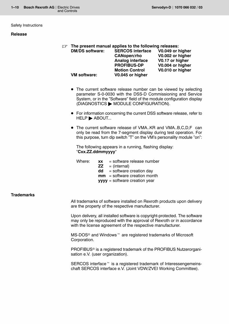
Release
. The present manual applies to the following releases:DM/DS software: SERCOS interface V0.049 or higher
CANopen/rho V0.002 or higherAnalog interface V0.17 or higherPROFIBUS-DP V0.004 or higherMotion Control V0.010 or higher
VM software: V0.045 or higher
D The current software release number can be viewed by selectingparameter S-0-0030 with the DSS-D Commissioning and ServiceSystem, or in the �Software� field of the module configuration display(DIAGNOSTICS " MODULE CONFIGURATION).
D For information concerning the current DSS software release, refer toHELP " ABOUT...
D The current software release of VMA..KR and VMA..B,C,D,F canonly be read from the 7-segment display during test operation. Forthis purpose, turn dip switch �T� on the VM�s personality module �on�:
The following appears in a running, flashing display:�Cxx.ZZ.ddmmyyyy�
Where: xx = software release numberZZ = (internal)dd = software creation daymm = software creation monthyyyy = software creation year
Trademarks
All trademarks of software installed on Rexroth products upon deliveryare the property of the respective manufacturer.
Upon delivery, all installed software is copyright-protected. The softwaremay only be reproduced with the approval of Rexroth or in accordancewith the license agreement of the respective manufacturer.
MS-DOSr and Windowst are registered trademarks of MicrosoftCorporation.
PROFIBUSr is a registered trademark of the PROFIBUS Nutzerorgani-sation e.V. (user organization).
SERCOS interfacet is a registered trademark of Interessengemeins-chaft SERCOS interface e.V. (Joint VDW/ZVEI Working Committee).
Electric Drivesand Controls
2�1Bosch Rexroth AGServodyn-D1070 066 032 / 03
Mains connection at the place of installation
2 Mains connection at the place of installation
CAUTIONA reversed phase sequence or winding direction of a line reactorwill destroy the mains connection module.Please ensure proper wiring.
2.1 Earthing
CAUTIONInverter modules may only be operated with an earthed neutralsystem.Systems not directly earthed (IT protective system) must not beused for operation, as air clearances and leakage paths in themodule may be overloaded.Operation at asymmetrical mains systems (TT protective system,one mains phase is earthed) is not permissible!
DIN VDE 0100-300 defines mains systems subject to their type of earthconnection.Accordingly, in an IT protective system, all active parts are separatedfrom earth, or one point is connected to earth via a resistor.The exposed conductive parts of an electrical system are eitherD earthed separately, orD earthed jointly, orD jointly connected to the system earth.
. Please note the information on earthing in the Servodyn-D EMCmanual, for part no. refer to page 1�9.
DANGEROUS ELECTRICAL VOLTAGEThe only permissible protective measure in accordance withEN 50 178 is a protective earth connection.The protective conductor must at least have the same area as themains feeder.Earthing only one end of the DC link when operating by means ofan isolating transformer is prohibited!
2�2 Electric Drivesand Controls
Bosch Rexroth AG Servodyn-D 1070 066 032 / 03
Mains connection at the place of installation
Earth connections in the switch cabinet must be designed in the form of agrid mesh.The module housing and mounting plate of the switch cabinet must beearthed. The connection between the line filter and the supply moduleshould be as short as possible.The protective earth cross-section must at least correspond to the cross-section of the line feeder of the supply module.
DANGERDangerous shock currents through inappropriate protective earthconnections!Do not impair protective earth connections by mechanical, chemi-cal or electro-chemical influences. The connection must be firmand lasting.
Electric Drivesand Controls
2�3Bosch Rexroth AGServodyn-D1070 066 032 / 03
Mains connection at the place of installation
2.2 Earth-leakage circuit-breaker
Inverters incorporate switched power units which are always associatedwith capacitive leakage currents against earth. The leakage currentsmay depend on the number of inverters, the earthing conditions as wellas the design and length of motor power cables.
Mains filters and shielded cables used to improve the electromagneticcompatibility (EMC) increase the leakage currents further. For this rea-son, no earth-leakage circuit-breakers with nominal leakage currents ofless than 300 mA may be used.
DANGEROUS ELECTRICAL VOLTAGEPersonnel protection is only guaranteed if earth-leakage circuit-breakers with nominal leakage currents of less than 30 mA areused.
. Inductors and/or capacitors present in the electric circuit may leadto spurious trips. If radio interference suppression filters are used,spurious trips can only be avoided by installing an isolating trans-former.
DANGEROUS ELECTRICAL VOLTAGEIf a pulse power current sensitive e.l.c.b. type A in accordance withIEC-755 (VDE 0664) is used, its protective function is not guaran-teed for inverters with a 3-phase mains connection (B6 circuit).
The protection of all electrical components connected together with in-verters with a 3-phase mains connection to a pulse power current sensi-tive e.l.c.b. may be adversely affected.Therefore, you should either install an isolating transformer with a pro-tective device and earthing in the mains feeder, or use a universal cur-rent sensitive e.l.c.b. type B which also provides safety disconnection inthe event of DC leakage currents.

2�4 Electric Drivesand Controls
Bosch Rexroth AG Servodyn-D 1070 066 032 / 03
Mains connection at the place of installation
Notes:
Electric Drivesand Controls
3�1Bosch Rexroth AGServodyn-D1070 066 032 / 03
Marks, certifications
3 Marks, certifications
3.1 CE-marking
Low-Voltage Directive
The CE marking confirms compliance of drive modules of the Servodyn-D series with the Low-Voltage Directive. The rating and construction sat-isfy the requirements of EN 50178.
Machinery Directive
The CE marking confirms compliance of drive modules of the Servodyn-D series with the Machinery Directive. The rating and construction sat-isfy the requirements of EN 60204-1.
EMC Directive
Concerning the EMC Directive, the exception stipulated in the GermanEMC Act, EMVG Art. 6, Subs. (9), is applicable, cf. below.The following must be noted with respect to the operational system (cf.EMC manual):D Requirements on EMC noise emission
D Conducted noiseDepending on the application (industrial environment or domesticapplication), a suitable mains filter is to be provided in the powersupply line.The cubicle construction should be designed so as to ensure theefficiency of the mains filter to the greatest possible extent.
D Radiated noiseDepending on the application (industrial environment or domesticapplication), a suitable switch cabinet with EMC shielding has tobe provided.For the motor leads, shielded cables should be preferably usedwhich are grounded on both ends of the shield.
D Required interference immunityThe rating and construction satisfy the requirements of the EMCproduct standard EN 61800-3 for application in industrial environ-ments.
EMVG 18.09.1998Art. 6 Exceptions and special determinations(9)Apparatuses, systems, and components covered by Subs. 3, which
are exclusively manufactured and designed as accessories or spareparts for further processing by companies or persons with expertknowledge in the field of electromagnetic compatibility, are exemptedfrom compliance with the protection requirements and the require-ments of Art. 4 Subs. 1 Nos. 1 to 3 and 5. The operational unit whichcontains apparatuses, systems or components defined in the 1st sen-tence above, shall satisfy the provisions of this law.
3�2 Electric Drivesand Controls
Bosch Rexroth AG Servodyn-D 1070 066 032 / 03
Marks, certifications
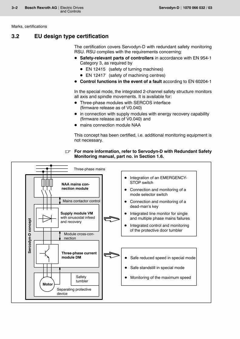
3.2 EU design type certification
The certification covers Servodyn-D with redundant safety monitoringRSU. RSU complies with the requirements concerning:D Safety-relevant parts of controllers in accordance with EN 954-1
Category 3, as required byD EN 12415 (safety of turning machines)D EN 12417 (safety of machining centres)
D Control functions in the event of a fault according to EN 60204-1
In the special mode, the integrated 2-channel safety structure monitorsall axis and spindle movements. It is available for:D Three-phase modules with SERCOS interface
(firmware release as of V0.040)D in connection with supply modules with energy recovery capability
(firmware release as of V0.040) andD mains connection module NAA
This concept has been certified, i.e. additional monitoring equipment isnot necessary.
. For more information, refer to Servodyn-D with Redundant SafetyMonitoring manual, part no. in Section 1.6.
NAA mains con-nection module
Supply module VMwith sinusoidal infeedand recovery
Three-phase currentmodule DM
Separating protective device
Three-phase mains
Safetytumbler
Module cross�con�nection
D Integration of an EMERGENCY-STOP switch
D Connection and monitoring of amode selector switch
D Connection and monitoring of adead-man�s key
D Integrated line monitor for singleand multiple phase mains failures
D Integrated control and monitoringof the protective door tumbler
D Safe reduced speed in special mode
D Safe standstill in special mode
D Monitoring of the maximum speed
Mains contactor control
Motor
Ser
cod
yn-D
co
nce
pt
Electric Drivesand Controls
3�3Bosch Rexroth AGServodyn-D1070 066 032 / 03
Marks, certifications
3.3 UL/CSA certification
For a number of Servodyn-D modules in compact mechanics, a UL/CSAcertification is available for the U.S. and Canada. They are marked byadhesive labels. These modules are listed in the �Product Identity 23MB�, File No. E214694.
Installation in compliance with UL/CSA
In order to obtain a UL/CSA-compliant installation, the following must benoted in addition to the use of the certified components:D Systems may only be used in environments with pollution severity 2.D Note tightening torques of the connection terminals as specified in In-
terface Conditions manual, for part no. refer to page 1�9.D The insulated wires must be specified for 60/75_C as a minimum.D Only insulated Class 1 wires or equivalent may be used,
e.g. to UL Style 1015 (on motor side, H07: U0/U: 600/1000 V) and ULStyle 1007 or 1569 (on supply side, H05: U0/U: 300/500 V)
D Suitable for installation in symmetrical supply networks with a short-circuit current of � 10 kA with max. 460 V +10 %.
Operation in compliance with UL/CSA
For UL/CSA-compliant operation, the bimetal function (I2t monitoring)must be activated in the inverters using parameter P-0-0053 in order toprovide motor protection.D IN of the motor is automatically retrieved from the electronic rating
plate to the I2t monitoring function.D P-0-0053 is only used to set the desired time constant:
Factory setting: 0.0 (disabled)Customary setting range: 100...150
(corresponds to release characteristics ofbimetal relay)

3�4 Electric Drivesand Controls
Bosch Rexroth AG Servodyn-D 1070 066 032 / 03
Marks, certifications
Notes:
Electric Drivesand Controls
4�1Bosch Rexroth AGServodyn-D1070 066 032 / 03
VMA..KB, VMA..KE status, warning and error displays
4 Diagnostics displays at the drive
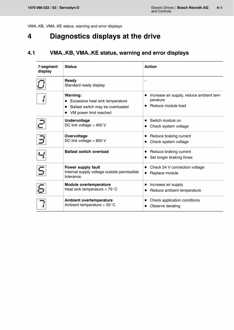
4.1 VMA..KB, VMA..KE status, warning and error displays
7-segmentdisplay
Status Action
ReadyStandard ready display
�
Warning:D Excessive heat sink temperature
D Ballast switch may be overloaded
D VM power limit reached
D Increase air supply, reduce ambient tem-perature
D Reduce module load
UndervoltageDC link voltage < 400 V
D Switch module on
D Check system voltage
OvervoltageDC link voltage > 800 V
D Reduce braking current
D Check system voltage
Ballast switch overload D Reduce braking current
D Set longer braking times
Power supply faultInternal supply voltage outside permissibletolerance.
D Check 24 V connection voltage
D Replace module
Module overtemperatureHeat sink temperature > 75_C
D Increase air supply
D Reduce ambient temperature
Ambient overtemperatureAmbient temperature > 55_C
D Check application conditions
D Observe derating
4�2 Electric Drivesand Controls
Bosch Rexroth AG Servodyn-D 1070 066 032 / 03
VMA..KR, VMA..B,C,D,F status displays
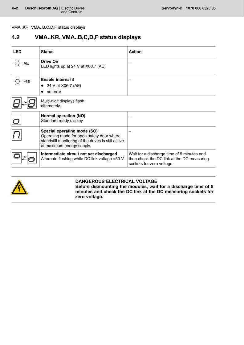
4.2 VMA..KR, VMA..B,C,D,F status displays
LED Status Action
AE Drive OnLED lights up at 24 V at X06.7 (AE)
�
FGI Enable internal ifD 24 V at X06.7 (AE)
D no error
�
Multi-digit displays flash alternately.
Normal operation (NO)Standard ready display
�
Special operating mode (SO)Operating mode for open safety door wherestandstill monitoring of the drives is still activeat maximum energy supply.
�
Intermediate circuit not yet dischargedAlternate flashing while DC link voltage >50 V
Wait for a discharge time of 5 minutes andthen check the DC link at the DC measuringsockets for zero voltage.
DANGEROUS ELECTRICAL VOLTAGEBefore dismounting the modules, wait for a discharge time of 5minutes and check the DC link at the DC measuring sockets forzero voltage.
Electric Drivesand Controls
4�3Bosch Rexroth AGServodyn-D1070 066 032 / 03
VMA..KR, VMA..B,C,D,F warning displays
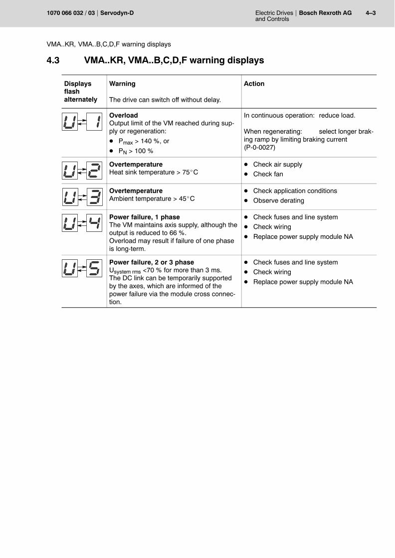
4.3 VMA..KR, VMA..B,C,D,F warning displays
Displaysflashalternately
Warning
The drive can switch off without delay.
Action
OverloadOutput limit of the VM reached during sup-ply or regeneration:
D Pmax > 140 %, or
D PN > 100 %
In continuous operation: reduce load.
When regenerating: select longer brak-ing ramp by limiting braking current(P-0-0027)
OvertemperatureHeat sink temperature > 75_C
D Check air supply
D Check fan
OvertemperatureAmbient temperature > 45_C
D Check application conditions
D Observe derating
Power failure, 1 phaseThe VM maintains axis supply, although theoutput is reduced to 66 %.Overload may result if failure of one phaseis long-term.
D Check fuses and line system
D Check wiring
D Replace power supply module NA
Power failure, 2 or 3 phaseUsystem rms <70 % for more than 3 ms.The DC link can be temporarily supportedby the axes, which are informed of thepower failure via the module cross connec-tion.
D Check fuses and line system
D Check wiring
D Replace power supply module NA
4�4 Electric Drivesand Controls
Bosch Rexroth AG Servodyn-D 1070 066 032 / 03
Status displays DM and DS (without frequency inverter)
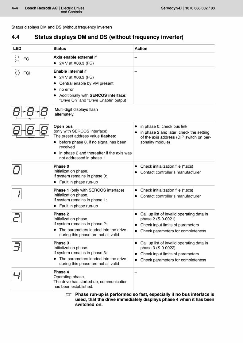
4.4 Status displays DM and DS (without frequency inverter)
LED Status Action
FG Axis enable external ifD 24 V at X06.3 (FG)
�
FGI Enable internal ifD 24 V at X06.3 (FG)
D Central enable by VM present
D no error
D Additionally with SERCOS interface:�Drive On� and �Drive Enable� output
�
Multi-digit displays flash alternately.
Open bus(only with SERCOS interface)The preset address value flashes:
D before phase 0, if no signal has beenreceived
D in phase 2 and thereafter if the axis wasnot addressed in phase 1
D in phase 0: check bus link
D in phase 2 and later: check the settingof the axis address (DIP switch on per-sonality module)
Phase 0Initialization phase.If system remains in phase 0:
D Fault in phase run-up
D Check initialization file (*.scs)
D Contact controller�s manufacturer
Phase 1 (only with SERCOS interface)Initialization phase.If system remains in phase 1:
D Fault in phase run-up
D Check initialization file (*.scs)
D Contact controller�s manufacturer
Phase 2Initialization phase.If system remains in phase 2:
D The parameters loaded into the driveduring this phase are not all valid
D Call up list of invalid operating data inphase 2 (S-0-0021)
D Check input limits of parameters
D Check parameters for completeness
Phase 3Initialization phase.If system remains in phase 3:
D The parameters loaded into the driveduring this phase are not all valid
D Call up list of invalid operating data inphase 3 (S-0-0022)
D Check input limits of parameters
D Check parameters for completeness
Phase 4Operating phase.The drive has started up, communicationhas been established.
�
. Phase run-up is performed so fast, especially if no bus interface isused, that the drive immediately displays phase 4 when it has beenswitched on.
Electric Drivesand Controls
4�5Bosch Rexroth AGServodyn-D1070 066 032 / 03
VMA..KR, VMA..B,C,D,F and DM/DS error displays
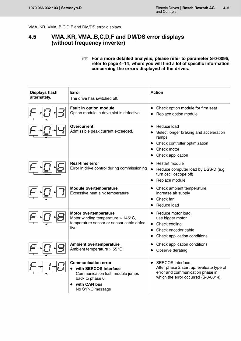
4.5 VMA..KR, VMA..B,C,D,F and DM/DS error displays(without frequency inverter)
. For a more detailed analysis, please refer to parameter S-0-0095,refer to page 4�14, where you will find a lot of specific informationconcerning the errors displayed at the drives.
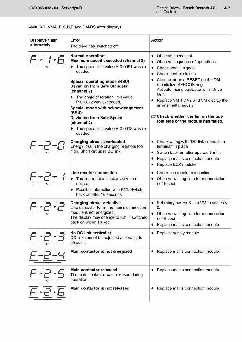
Displays flashalternately.
ErrorThe drive has switched off.
Action
Fault in option moduleOption module in drive slot is defective.
D Check option module for firm seat
D Replace option module
OvercurrentAdmissible peak current exceeded.
D Reduce load
D Select longer braking and accelerationramps
D Check controller optimization
D Check motor
D Check application
Real-time errorError in drive control during commissioning
D Restart module
D Reduce computer load by DSS-D (e.g.turn oscilloscope off)
D Replace module
Module overtemperatureExcessive heat sink temperature
D Check ambient temperature, increase air supply
D Check fan
D Reduce load
Motor overtemperatureMotor winding temperature > 145_C,temperature sensor or sensor cable defec-tive.
D Reduce motor load,use bigger motor
D Check cooling
D Check encoder cable
D Check application conditions
Ambient overtemperatureAmbient temperature > 55_C
D Check application conditions
D Observe derating
Communication error D with SERCOS interface
Communication lost, module jumpsback to phase 0.
D with CAN busNo SYNC message
D SERCOS interface:After phase 2 start up, evaluate type oferror and communication phase inwhich the error occurred (S-0-0014).
4�6 Electric Drivesand Controls
Bosch Rexroth AG Servodyn-D 1070 066 032 / 03
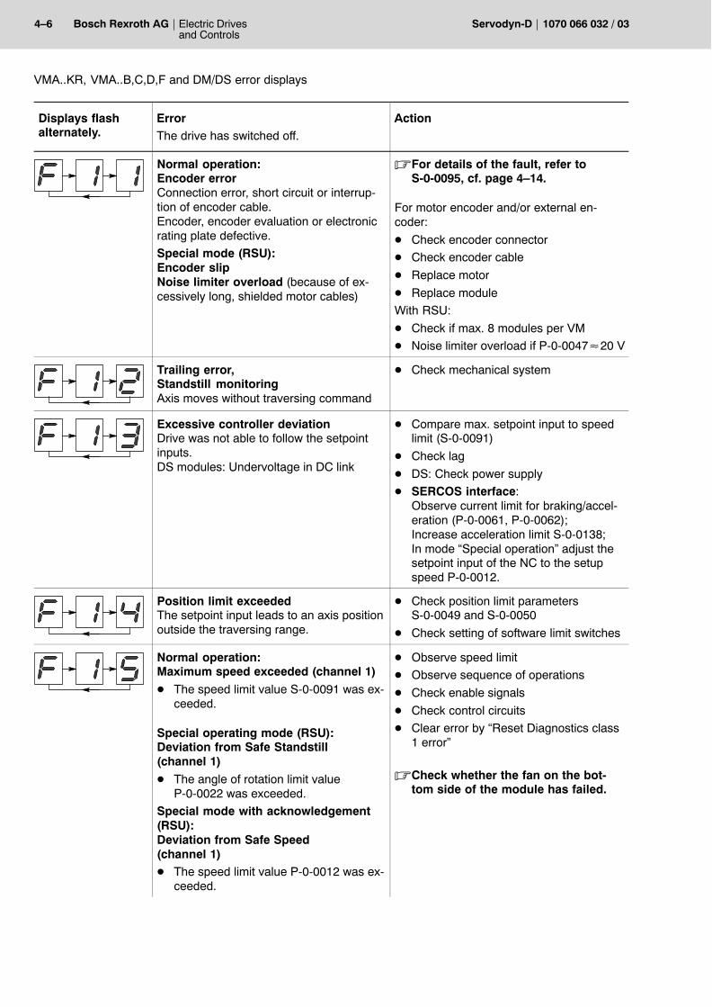
VMA..KR, VMA..B,C,D,F and DM/DS error displays
Displays flashalternately.
ActionErrorThe drive has switched off.
Normal operation:Encoder errorConnection error, short circuit or interrup-tion of encoder cable. Encoder, encoder evaluation or electronicrating plate defective.
Special mode (RSU):Encoder slipNoise limiter overload (because of ex-cessively long, shielded motor cables)
.For details of the fault, refer toS-0-0095, cf. page 4�14.
For motor encoder and/or external en-coder:
D Check encoder connector
D Check encoder cable
D Replace motor
D Replace module
With RSU:
D Check if max. 8 modules per VM
D Noise limiter overload if P-0-0047�20 V
Trailing error,Standstill monitoringAxis moves without traversing command
D Check mechanical system
Excessive controller deviationDrive was not able to follow the setpointinputs.DS modules: Undervoltage in DC link
D Compare max. setpoint input to speedlimit (S-0-0091)
D Check lag
D DS: Check power supply
D SERCOS interface: Observe current limit for braking/accel-eration (P-0-0061, P-0-0062);Increase acceleration limit S-0-0138;In mode �Special operation� adjust thesetpoint input of the NC to the setupspeed P-0-0012.
Position limit exceededThe setpoint input leads to an axis positionoutside the traversing range.
D Check position limit parametersS-0-0049 and S-0-0050
D Check setting of software limit switches
Normal operation:Maximum speed exceeded (channel 1)
D The speed limit value S-0-0091 was ex-ceeded.
Special operating mode (RSU):Deviation from Safe Standstill(channel 1)
D The angle of rotation limit valueP-0-0022 was exceeded.
Special mode with acknowledgement(RSU):Deviation from Safe Speed(channel 1)D The speed limit value P-0-0012 was ex-
ceeded.
D Observe speed limit
D Observe sequence of operations
D Check enable signals
D Check control circuits
D Clear error by �Reset Diagnostics class1 error�
.Check whether the fan on the bot-tom side of the module has failed.
Electric Drivesand Controls
4�7Bosch Rexroth AGServodyn-D1070 066 032 / 03
VMA..KR, VMA..B,C,D,F and DM/DS error displays
Displays flashalternately.
ActionErrorThe drive has switched off.
Normal operation:Maximum speed exceeded (channel 2)
D The speed limit value S-0-0091 was ex-ceeded.
Special operating mode (RSU):Deviation from Safe Standstill(channel 2)
D The angle of rotation limit valueP-0-0022 was exceeded.
Special mode with acknowledgement(RSU):Deviation from Safe Speed(channel 2)D The speed limit value P-0-0012 was ex-
ceeded.
D Observe speed limit
D Observe sequence of operations
D Check enable signals
D Check control circuits
D Clear error by a RESET on the DM,re-initialize SERCOS ring.Activate mains contactor with �DriveOn�.
D Replace VM if DMs and VM display theerror simultaneously
.Check whether the fan on the bot-tom side of the module has failed.
Charging circuit overloadedEnergy loss in the charging resistors toohigh. Short circuit in DC link.
D Check wiring with �DC link connectionterminal� in place
D Switch back on after approx. 5 min.
D Replace mains connection module
D Replace EBX module
Line reactor connectionD The line reactor is incorrectly con-
nected.
D Possible interaction with F22: Switchback on after 16 seconds
D Check line reactor connection
D Observe waiting time for reconnection(> 16 sec)
Charging circuit defectiveLine contactor K1 in the mains connectionmodule is not energized.The display may change to F21 if switchedback on within 16 sec.
D Set rotary switch S1 on VM to values >0.
D Observe waiting time for reconnection(> 16 sec)
D Replace mains connection module
No DC link controllerDC link cannot be adjusted according tosetpoint.
D Replace supply module
Main contactor is not energized D Replace mains connection module
Main contactor releasedThe main contactor was released duringoperation.
D Replace mains connection module
Main contactor is not released D Replace mains connection module
4�8 Electric Drivesand Controls
Bosch Rexroth AG Servodyn-D 1070 066 032 / 03
VMA..KR, VMA..B,C,D,F and DM/DS error displays
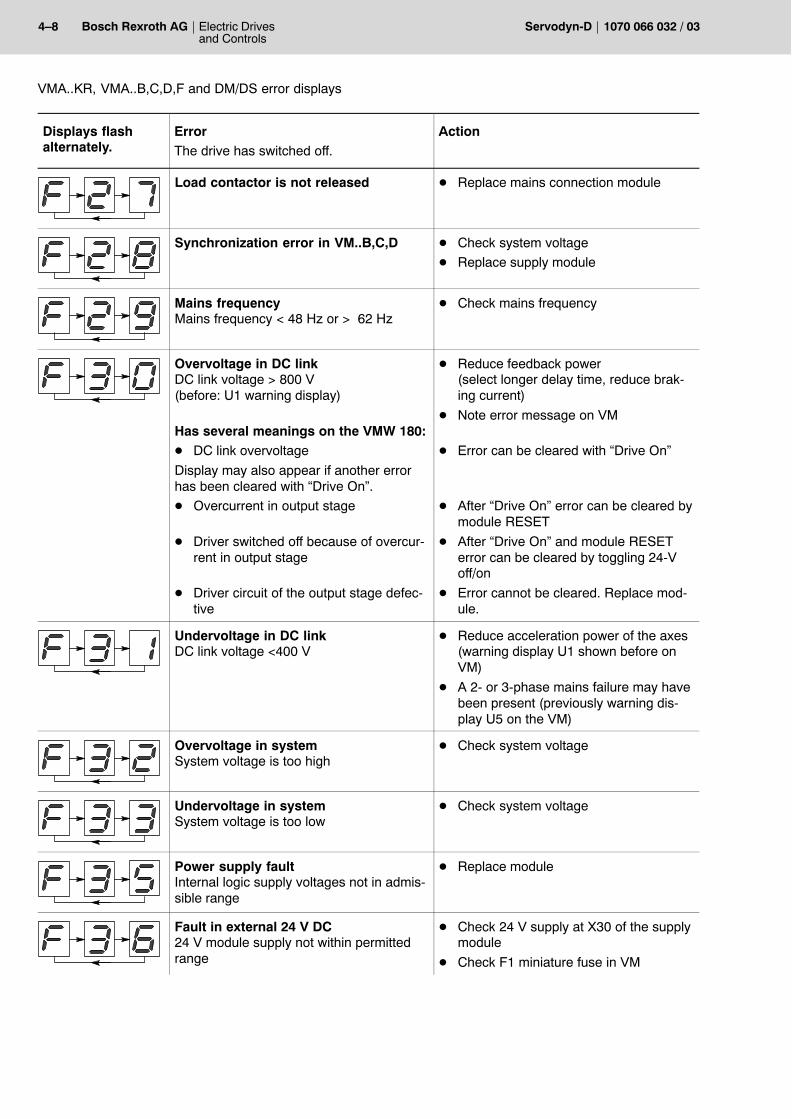
Displays flashalternately.
ActionErrorThe drive has switched off.
Load contactor is not released D Replace mains connection module
Synchronization error in VM..B,C,D D Check system voltage
D Replace supply module
Mains frequencyMains frequency < 48 Hz or > 62 Hz
D Check mains frequency
Overvoltage in DC linkDC link voltage > 800 V(before: U1 warning display)
Has several meanings on the VMW 180:D DC link overvoltage
Display may also appear if another errorhas been cleared with �Drive On�.
D Overcurrent in output stage
D Driver switched off because of overcur-rent in output stage
D Driver circuit of the output stage defec-tive
D Reduce feedback power(select longer delay time, reduce brak-ing current)
D Note error message on VM
D Error can be cleared with �Drive On�
D After �Drive On� error can be cleared bymodule RESET
D After �Drive On� and module RESETerror can be cleared by toggling 24-Voff/on
D Error cannot be cleared. Replace mod-ule.
Undervoltage in DC linkDC link voltage <400 V
D Reduce acceleration power of the axes(warning display U1 shown before onVM)
D A 2- or 3-phase mains failure may havebeen present (previously warning dis-play U5 on the VM)
Overvoltage in systemSystem voltage is too high
D Check system voltage
Undervoltage in systemSystem voltage is too low
D Check system voltage
Power supply faultInternal logic supply voltages not in admis-sible range
D Replace module
Fault in external 24 V DC 24 V module supply not within permittedrange
D Check 24 V supply at X30 of the supplymodule
D Check F1 miniature fuse in VM
Electric Drivesand Controls
4�9Bosch Rexroth AGServodyn-D1070 066 032 / 03
VMA..KR, VMA..B,C,D,F and DM/DS error displays
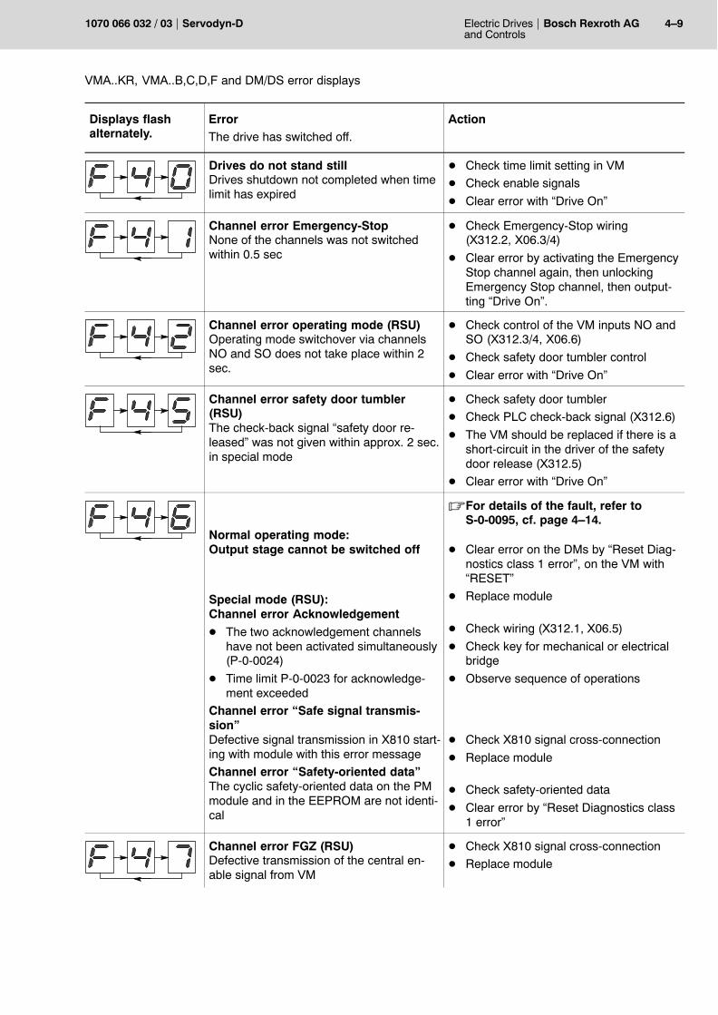
Displays flashalternately.
ActionErrorThe drive has switched off.
Drives do not stand stillDrives shutdown not completed when timelimit has expired
D Check time limit setting in VM
D Check enable signals
D Clear error with �Drive On�
Channel error Emergency-StopNone of the channels was not switchedwithin 0.5 sec
D Check Emergency-Stop wiring (X312.2, X06.3/4)
D Clear error by activating the EmergencyStop channel again, then unlockingEmergency Stop channel, then output-ting �Drive On�.
Channel error operating mode (RSU)Operating mode switchover via channelsNO and SO does not take place within 2sec.
D Check control of the VM inputs NO andSO (X312.3/4, X06.6)
D Check safety door tumbler control
D Clear error with �Drive On�
Channel error safety door tumbler(RSU)The check-back signal �safety door re-leased� was not given within approx. 2 sec.in special mode
D Check safety door tumbler
D Check PLC check-back signal (X312.6)
D The VM should be replaced if there is ashort-circuit in the driver of the safetydoor release (X312.5)
D Clear error with �Drive On�
Normal operating mode:Output stage cannot be switched off
Special mode (RSU):Channel error Acknowledgement
D The two acknowledgement channelshave not been activated simultaneously(P-0-0024)
D Time limit P-0-0023 for acknowledge-ment exceeded
Channel error �Safe signal transmis-sion�Defective signal transmission in X810 start-ing with module with this error message
Channel error �Safety-oriented data�The cyclic safety-oriented data on the PMmodule and in the EEPROM are not identi-cal
.For details of the fault, refer toS-0-0095, cf. page 4�14.
D Clear error on the DMs by �Reset Diag-nostics class 1 error�, on the VM with�RESET�
D Replace module
D Check wiring (X312.1, X06.5)
D Check key for mechanical or electricalbridge
D Observe sequence of operations
D Check X810 signal cross-connection
D Replace module
D Check safety-oriented data
D Clear error by �Reset Diagnostics class1 error�
Channel error FGZ (RSU)Defective transmission of the central en-able signal from VM
D Check X810 signal cross-connection
D Replace module
4�10 Electric Drivesand Controls
Bosch Rexroth AG Servodyn-D 1070 066 032 / 03
VMA..KR, VMA..B,C,D,F and DM/DS error displays
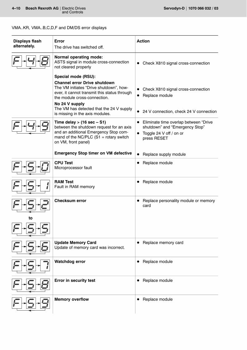
Displays flashalternately.
ActionErrorThe drive has switched off.
Normal operating mode:ASTS signal in module cross-connectionnot cleared properly
Special mode (RSU):
Channel error Drive shutdownThe VM initiates �Drive shutdown�, how-ever, it cannot transmit this status throughthe module cross-connection.
No 24 V supplyThe VM has detected that the 24 V supplyis missing in the axis modules.
D Check X810 signal cross-connection
D Check X810 signal cross-connection
D Replace module
D 24 V connection, check 24 V connection
Time delay > (16 sec � S1)between the shutdown request for an axisand an additional Emergency Stop com-mand of the NC/PLC (S1 = rotary switchon VM, front panel)
Emergency Stop timer on VM defective
D Eliminate time overlap between �Driveshutdown� and �Emergency Stop�
D Toggle 24 V off / on or press RESET
D Replace supply module
CPU TestMicroprocessor fault
D Replace module
RAM TestFault in RAM memory
D Replace module
to
Checksum error D Replace personality module or memorycard
Update Memory CardUpdate of memory card was incorrect.
D Replace memory card
Watchdog error D Replace module
Error in security test D Replace module
Memory overflow D Replace module
Electric Drivesand Controls
4�11Bosch Rexroth AGServodyn-D1070 066 032 / 03
VMA..KR, VMA..B,C,D,F and DM/DS error displays
Displays flashalternately.
ActionErrorThe drive has switched off.
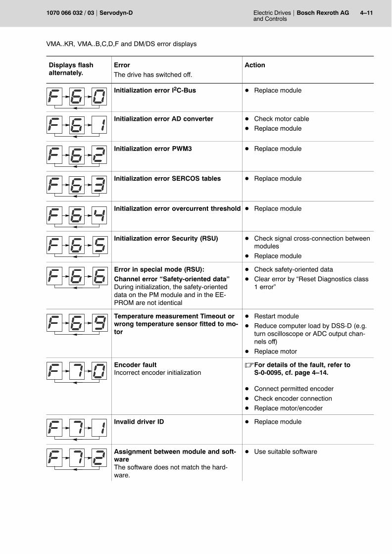
Initialization error I2C-Bus D Replace module
Initialization error AD converter D Check motor cable
D Replace module
Initialization error PWM3 D Replace module
Initialization error SERCOS tables D Replace module
Initialization error overcurrent threshold D Replace module
Initialization error Security (RSU) D Check signal cross-connection betweenmodules
D Replace module
Error in special mode (RSU):Channel error �Safety-oriented data�During initialization, the safety-orienteddata on the PM module and in the EE-PROM are not identical
D Check safety-oriented data
D Clear error by �Reset Diagnostics class1 error�
Temperature measurement Timeout orwrong temperature sensor fitted to mo-tor
D Restart module
D Reduce computer load by DSS-D (e.g.turn oscilloscope or ADC output chan-nels off)
D Replace motor
Encoder faultIncorrect encoder initialization
.For details of the fault, refer toS-0-0095, cf. page 4�14.
D Connect permitted encoder
D Check encoder connection
D Replace motor/encoder
Invalid driver ID D Replace module
Assignment between module and soft-wareThe software does not match the hard-ware.
D Use suitable software
4�12 Electric Drivesand Controls
Bosch Rexroth AG Servodyn-D 1070 066 032 / 03
VMA..KR, VMA..B,C,D,F and DM/DS error displays
Displays flashalternately.
ActionErrorThe drive has switched off.
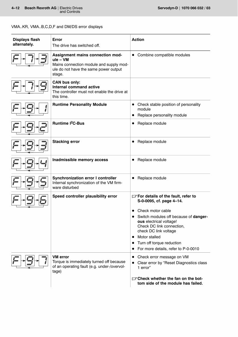
Assignment mains connection mod-ule � VMMains connection module and supply mod-ule do not have the same power outputstage.
D Combine compatible modules
CAN bus only:Internal command activeThe controller must not enable the drive atthis time.
Runtime Personality Module D Check stable position of personalitymodule
D Replace personality module
Runtime I2C-Bus D Replace module
Stacking error D Replace module
Inadmissible memory access D Replace module
Synchronization error I controllerInternal synchronization of the VM firm-ware disturbed
D Replace module
Speed controller plausibility error .For details of the fault, refer toS-0-0095, cf. page 4�14.
D Check motor cable
D Switch modules off because of danger-ous electrical voltage! Check DC link connection, check DC link voltage
D Motor stalled
D Turn off torque reduction
D For more details, refer to P-0-0010
VM errorTorque is immediately turned off becauseof an operating fault (e.g. under-/overvol-tage)
D Check error message on VM
D Clear error by �Reset Diagnostics class1 error�
.Check whether the fan on the bot-tom side of the module has failed.
Electric Drivesand Controls
4�13Bosch Rexroth AGServodyn-D1070 066 032 / 03
VMA..KR, VMA..B,C,D,F and DM/DS error displays
Displays flashalternately.
ActionErrorThe drive has switched off.
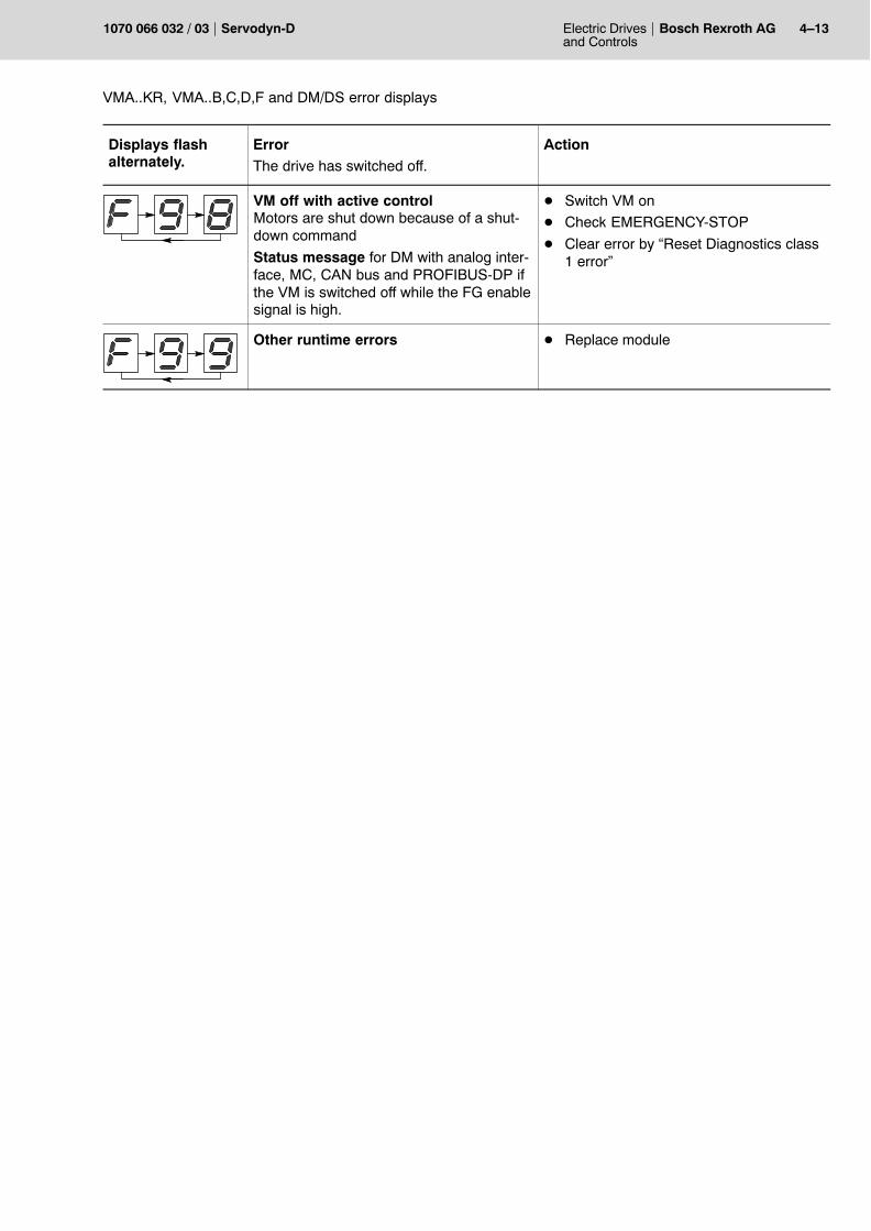
VM off with active controlMotors are shut down because of a shut-down command
Status message for DM with analog inter-face, MC, CAN bus and PROFIBUS-DP ifthe VM is switched off while the FG enablesignal is high.
D Switch VM on
D Check EMERGENCY-STOP
D Clear error by �Reset Diagnostics class1 error�
Other runtime errors D Replace module
4�14 Electric Drivesand Controls
Bosch Rexroth AG Servodyn-D 1070 066 032 / 03
VMA..KR, VMA..B,C,D,F and DM/DS error displays
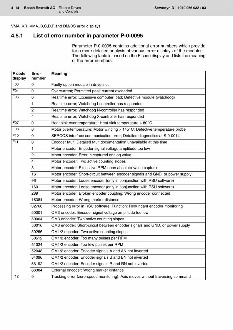
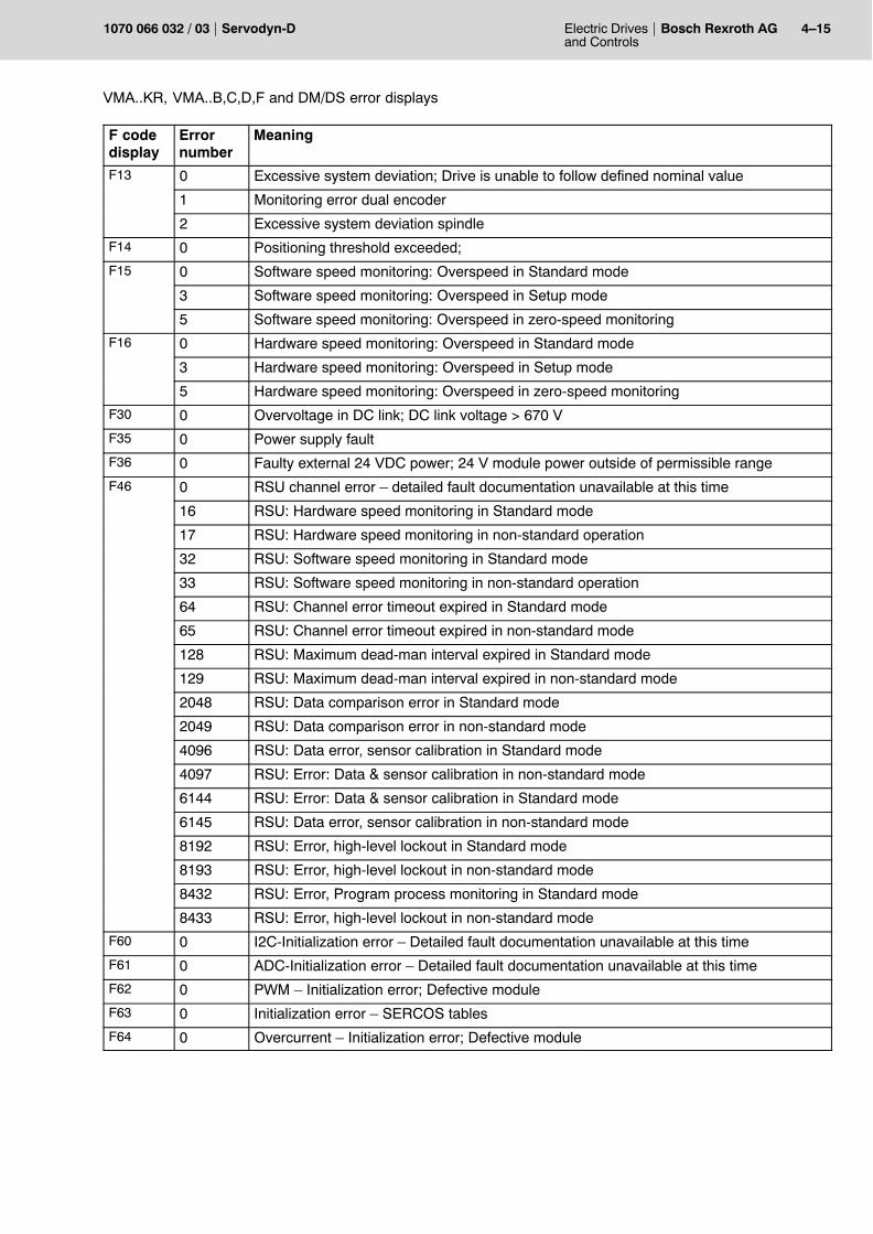
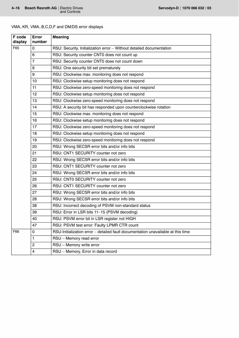
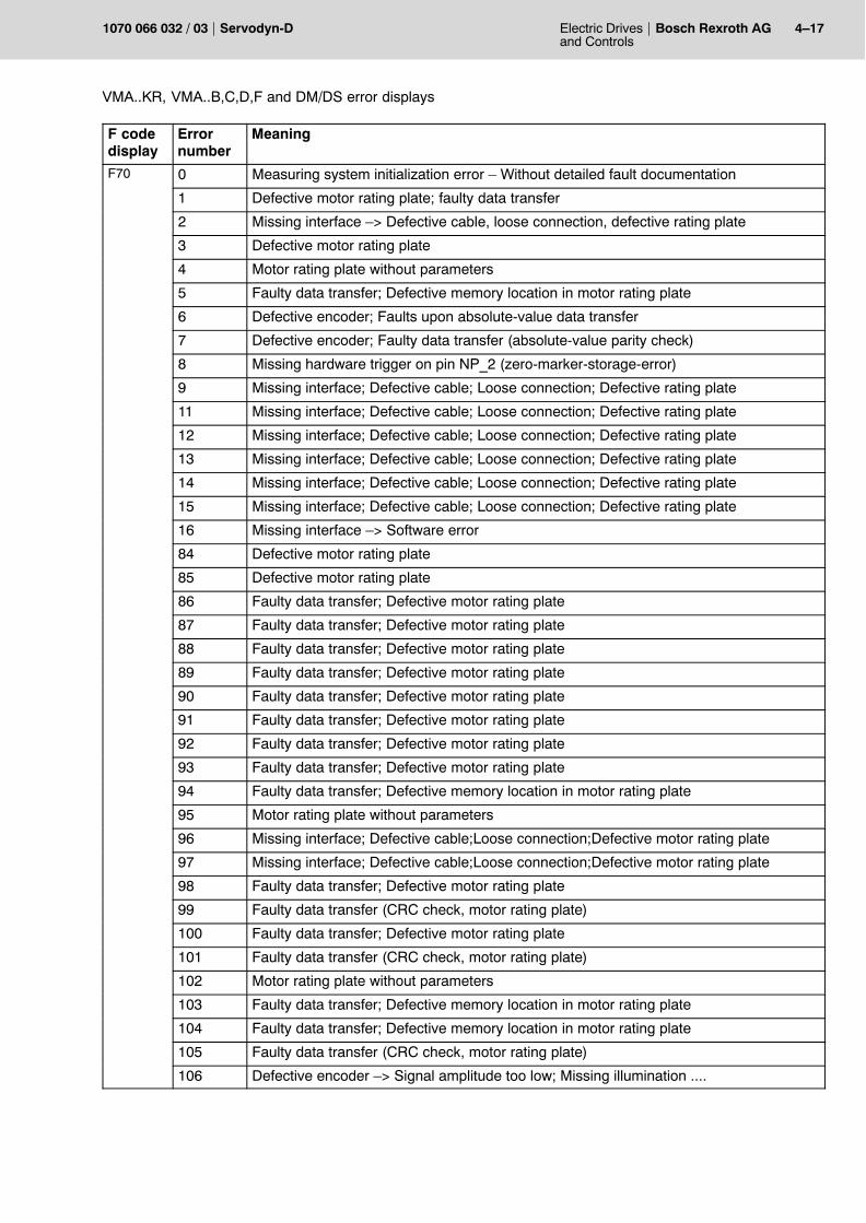
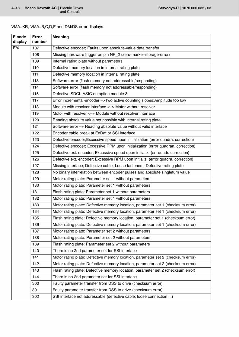
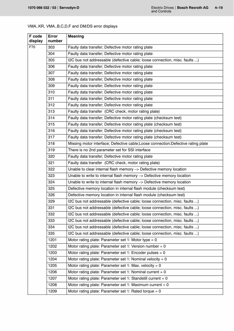
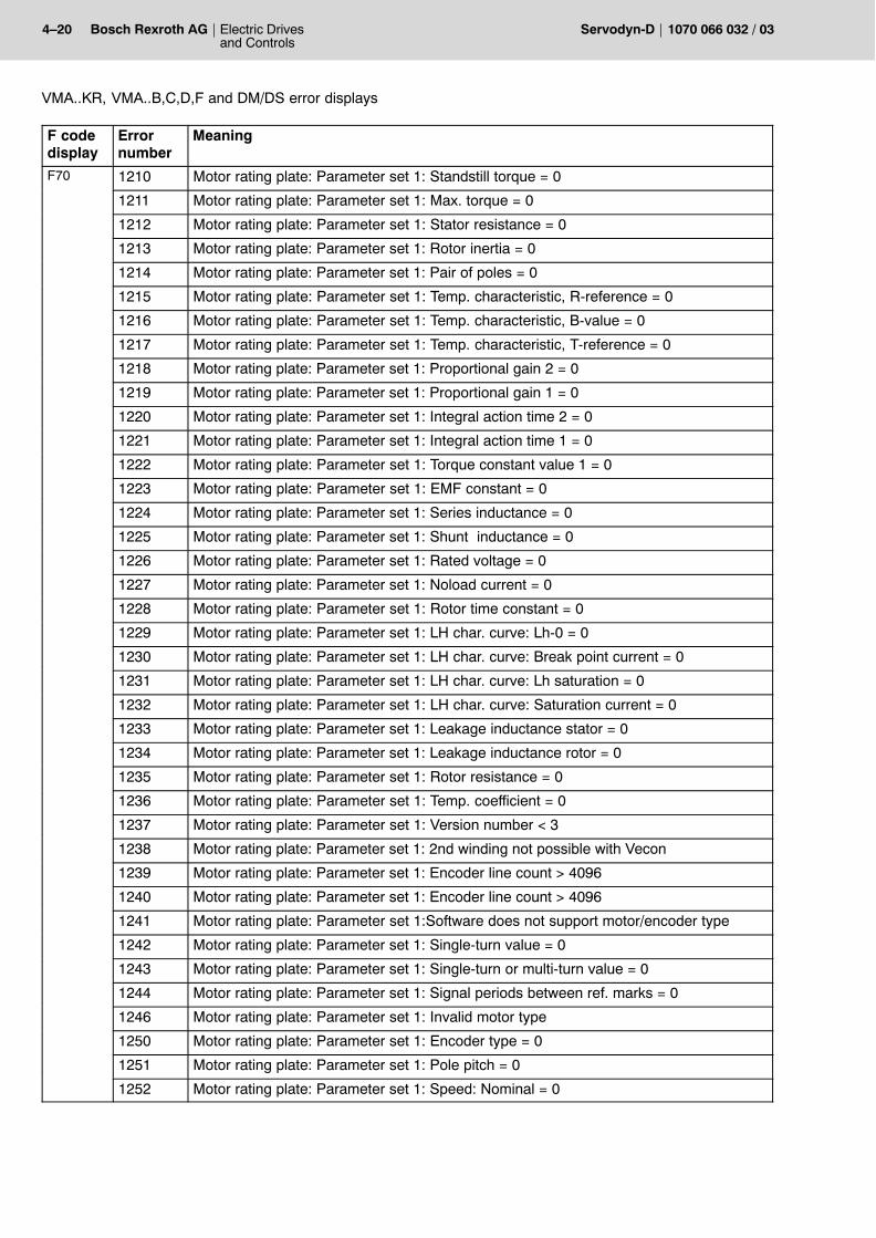
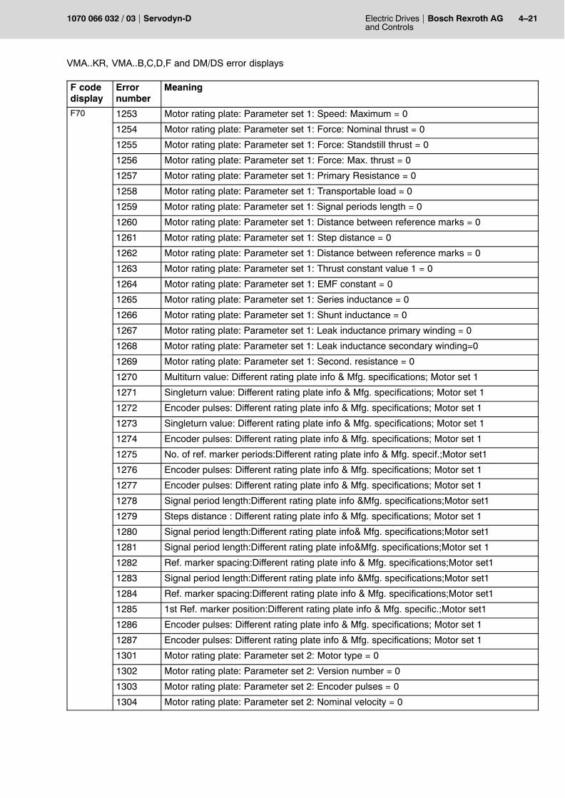
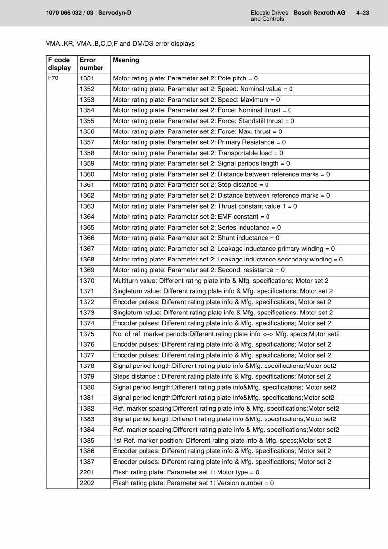
4.5.1 List of error number in parameter P-0-0095
Parameter P-0-0095 contains additional error numbers which providefor a more detailed analysis of various error displays of the modules. The following table is based on the F code display and lists the meaningof the error numbers:
F codedisplay
Errornumber
Meaning
F03 0 Faulty option module in drive slot
F04 0 Overcurrent; Permitted peak current exceeded
F06 0 Realtime error; Excessive computer load; Defective module (watchdog)
1 Realtime error; Watchdog I-controller has responded
2 Realtime error; Watchdog N-controller has responded
4 Realtime error; Watchdog X-controller has responded
F07 0 Heat sink overtemperature; Heat sink temperature > 80°C
F08 0 Motor overtemperature; Motor winding > 145°C; Defective temperature probe
F10 0 SERCOS interface communication error; Detailed diagnostics at S-0-0014
F11 0 Encoder fault; Detailed fault documentation unavailable at this time
1 Motor encoder: Encoder signal voltage amplitude too low
2 Motor encoder: Error in captured analog value
4 Motor encoder: Two active counting slopes
8 Motor encoder: Excessive RPM upon absolute-value capture
16 Motor encoder: Short-circuit between encoder signals and GND, or power supply
96 Motor encoder: Loose encoder (only in conjunction with RSU software)
160 Motor encoder: Loose encoder (only in conjunction with RSU software)
289 Motor encoder: Broken encoder coupling; Wrong encoder connected
16384 Motor encoder: Wrong marker distance
32768 Processing error in RSU software; Function: Redundant encoder monitoring
50001 OM3 encoder: Encoder signal voltage amplitude too low
50004 OM3 encoder: Two active counting slopes
50016 OM3 encoder: Short-circuit between encoder signals and GND, or power supply
50256 OM1/2 encoder: Two active counting slopes
50512 OM1/2 encoder: Too many pulses per RPM
51024 OM1/2 encoder: Too few pulses per RPM
52048 OM1/2 encoder: Encoder signals A and AN not inverted
54096 OM1/2 encoder: Encoder signals B and BN not inverted
58192 OM1/2 encoder: Encoder signals R and RN not inverted
66384 External encoder: Wrong marker distance
F12 0 Tracking error (zero-speed monitoring); Axis moves without traversing command
Electric Drivesand Controls
4�15Bosch Rexroth AGServodyn-D1070 066 032 / 03
VMA..KR, VMA..B,C,D,F and DM/DS error displays
F codedisplay
MeaningErrornumber
F13 0 Excessive system deviation; Drive is unable to follow defined nominal value
1 Monitoring error dual encoder
2 Excessive system deviation spindle
F14 0 Positioning threshold exceeded;
F15 0 Software speed monitoring: Overspeed in Standard mode
3 Software speed monitoring: Overspeed in Setup mode
5 Software speed monitoring: Overspeed in zero-speed monitoring
F16 0 Hardware speed monitoring: Overspeed in Standard mode
3 Hardware speed monitoring: Overspeed in Setup mode
5 Hardware speed monitoring: Overspeed in zero-speed monitoring
F30 0 Overvoltage in DC link; DC link voltage > 670 V
F35 0 Power supply fault
F36 0 Faulty external 24 VDC power; 24 V module power outside of permissible range
F46 0 RSU channel error � detailed fault documentation unavailable at this time
16 RSU: Hardware speed monitoring in Standard mode
17 RSU: Hardware speed monitoring in non-standard operation
32 RSU: Software speed monitoring in Standard mode
33 RSU: Software speed monitoring in non-standard operation
64 RSU: Channel error timeout expired in Standard mode
65 RSU: Channel error timeout expired in non-standard mode
128 RSU: Maximum dead-man interval expired in Standard mode
129 RSU: Maximum dead-man interval expired in non-standard mode
2048 RSU: Data comparison error in Standard mode
2049 RSU: Data comparison error in non-standard mode
4096 RSU: Data error, sensor calibration in Standard mode
4097 RSU: Error: Data & sensor calibration in non-standard mode
6144 RSU: Error: Data & sensor calibration in Standard mode
6145 RSU: Data error, sensor calibration in non-standard mode
8192 RSU: Error, high-level lockout in Standard mode
8193 RSU: Error, high-level lockout in non-standard mode
8432 RSU: Error, Program process monitoring in Standard mode
8433 RSU: Error, high-level lockout in non-standard mode
F60 0 I2C-Initialization error � Detailed fault documentation unavailable at this time
F61 0 ADC-Initialization error � Detailed fault documentation unavailable at this time
F62 0 PWM � Initialization error; Defective module
F63 0 Initialization error � SERCOS tables
F64 0 Overcurrent � Initialization error; Defective module
4�16 Electric Drivesand Controls
Bosch Rexroth AG Servodyn-D 1070 066 032 / 03
VMA..KR, VMA..B,C,D,F and DM/DS error displays
F codedisplay
MeaningErrornumber
F65 0 RSU: Security, Initialization error � Without detailed documentation
6 RSU: Security counter CNT0 does not count up
7 RSU: Security counter CNT0 does not count down
8 RSU: One security bit set prematurely
9 RSU: Clockwise max. monitoring does not respond
10 RSU: Clockwise setup monitoring does not respond
11 RSU: Clockwise zero-speed monitoring does not respond
12 RSU: Clockwise setup monitoring does not respond
13 RSU: Clockwise zero-speed monitoring does not respond
14 RSU: A security bit has responded upon counterclockwise rotation
15 RSU: Clockwise max. monitoring does not respond
16 RSU: Clockwise setup monitoring does not respond
17 RSU: Clockwise zero-speed monitoring does not respond
18 RSU: Clockwise setup monitoring does not respond
19 RSU: Clockwise zero-speed monitoring does not respond
20 RSU: Wrong SECSR error bits and/or info bits
21 RSU: CNT1 SECURITY counter not zero
22 RSU: Wrong SECSR error bits and/or info bits
23 RSU: CNT1 SECURITY counter not zero
24 RSU: Wrong SECSR error bits and/or info bits
25 RSU: CNT0 SECURITY counter not zero
26 RSU: CNT1 SECURITY counter not zero
27 RSU: Wrong SECSR error bits and/or info bits
28 RSU: Wrong SECSR error bits and/or info bits
38 RSU: Incorrect decoding of PSVM non-standard status
39 RSU: Error in LSR bits 11�15 (PSVM decoding)
40 RSU: PSVM error bit in LSR register not HIGH
47 RSU: PSVM test error: Faulty LPMR CTR count
F66 0 RSU-Initialization error � detailed fault documentation unavailable at this time
1 RSU � Memory read error
2 RSU � Memory write error
4 RSU � Memory, Error in data record
Electric Drivesand Controls
4�17Bosch Rexroth AGServodyn-D1070 066 032 / 03
VMA..KR, VMA..B,C,D,F and DM/DS error displays
F codedisplay
MeaningErrornumber
F70 0 Measuring system initialization error � Without detailed fault documentation
1 Defective motor rating plate; faulty data transfer
2 Missing interface �> Defective cable, loose connection, defective rating plate
3 Defective motor rating plate
4 Motor rating plate without parameters
5 Faulty data transfer; Defective memory location in motor rating plate
6 Defective encoder; Faults upon absolute-value data transfer
7 Defective encoder; Faulty data transfer (absolute-value parity check)
8 Missing hardware trigger on pin NP_2 (zero-marker-storage-error)
9 Missing interface; Defective cable; Loose connection; Defective rating plate
11 Missing interface; Defective cable; Loose connection; Defective rating plate
12 Missing interface; Defective cable; Loose connection; Defective rating plate
13 Missing interface; Defective cable; Loose connection; Defective rating plate
14 Missing interface; Defective cable; Loose connection; Defective rating plate
15 Missing interface; Defective cable; Loose connection; Defective rating plate
16 Missing interface �> Software error
84 Defective motor rating plate
85 Defective motor rating plate
86 Faulty data transfer; Defective motor rating plate
87 Faulty data transfer; Defective motor rating plate
88 Faulty data transfer; Defective motor rating plate
89 Faulty data transfer; Defective motor rating plate
90 Faulty data transfer; Defective motor rating plate
91 Faulty data transfer; Defective motor rating plate
92 Faulty data transfer; Defective motor rating plate
93 Faulty data transfer; Defective motor rating plate
94 Faulty data transfer; Defective memory location in motor rating plate
95 Motor rating plate without parameters
96 Missing interface; Defective cable;Loose connection;Defective motor rating plate
97 Missing interface; Defective cable;Loose connection;Defective motor rating plate
98 Faulty data transfer; Defective motor rating plate
99 Faulty data transfer (CRC check, motor rating plate)
100 Faulty data transfer; Defective motor rating plate
101 Faulty data transfer (CRC check, motor rating plate)
102 Motor rating plate without parameters
103 Faulty data transfer; Defective memory location in motor rating plate
104 Faulty data transfer; Defective memory location in motor rating plate
105 Faulty data transfer (CRC check, motor rating plate)
106 Defective encoder �> Signal amplitude too low; Missing illumination ....
4�18 Electric Drivesand Controls
Bosch Rexroth AG Servodyn-D 1070 066 032 / 03
VMA..KR, VMA..B,C,D,F and DM/DS error displays
F codedisplay
MeaningErrornumber
F70 107 Defective encoder; Faults upon absolute-value data transfer
108 Missing hardware trigger on pin NP_2 (zero-marker-storage-error)
109 Internal rating plate without parameters
110 Defective memory location in internal rating plate
111 Defective memory location in internal rating plate
113 Software error (flash memory not addressable/responding)
114 Software error (flash memory not addressable/responding)
115 Defective SDCL-ASIC on option module 3
117 Error incremental-encoder �>Two active counting slopes;Amplitude too low
118 Module with resolver interface <�> Motor without resolver
119 Motor with resolver <�> Module without resolver interface
120 Reading absolute value not possible with internal rating plate
121 Software error �> Reading absolute value without valid interface
122 Encoder cable break at EnDat or SSI interface
123 Defective encoder;Excessive speed upon initialization (error quadra. correction)
124 Defective encoder; Excessive RPM upon initialization (error quadran. correction)
125 Defective ext. encoder; Excessive speed upon initializ. (err quadr. correction)
126 Defective ext. encoder; Excessive RPM upon initializ. (error quadra. correction)
127 Missing interface; Defective cable; Loose fasteners; Defective rating plate
128 No binary interrelation between encoder pulses and absolute singleturn value
129 Motor rating plate: Parameter set 1 without parameters
130 Motor rating plate: Parameter set 1 without parameters
131 Flash rating plate: Parameter set 1 without parameters
132 Motor rating plate: Parameter set 1 without parameters
133 Motor rating plate: Defective memory location, parameter set 1 (checksum error)
134 Motor rating plate: Defective memory location, parameter set 1 (checksum error)
135 Flash rating plate: Defective memory location, parameter set 1 (checksum error)
136 Motor rating plate: Defective memory location, parameter set 1 (checksum error)
137 Motor rating plate: Parameter set 2 without parameters
138 Motor rating plate: Parameter set 2 without parameters
139 Flash rating plate: Parameter set 2 without parameters
140 There is no 2nd parameter set for SSI interface
141 Motor rating plate: Defective memory location, parameter set 2 (checksum error)
142 Motor rating plate: Defective memory location, parameter set 2 (checksum error)
143 Flash rating plate: Defective memory location, parameter set 2 (checksum error)
144 There is no 2nd parameter set for SSI interface
300 Faulty parameter transfer from DSS to drive (checksum error)
301 Faulty parameter transfer from DSS to drive (checksum error)
302 SSI interface not addressable (defective cable; loose connection ...)
Electric Drivesand Controls
4�19Bosch Rexroth AGServodyn-D1070 066 032 / 03
VMA..KR, VMA..B,C,D,F and DM/DS error displays
F codedisplay
MeaningErrornumber
F70 303 Faulty data transfer; Defective motor rating plate
304 Faulty data transfer; Defective motor rating plate
305 I2C bus not addressable (defective cable; loose connection, misc. faults ...)
306 Faulty data transfer; Defective motor rating plate
307 Faulty data transfer; Defective motor rating plate
308 Faulty data transfer; Defective motor rating plate
309 Faulty data transfer; Defective motor rating plate
310 Faulty data transfer; Defective motor rating plate
311 Faulty data transfer; Defective motor rating plate
312 Faulty data transfer; Defective motor rating plate
313 Faulty data transfer (CRC check, motor rating plate)
314 Faulty data transfer; Defective motor rating plate (checksum test)
315 Faulty data transfer; Defective motor rating plate (checksum test)
316 Faulty data transfer; Defective motor rating plate (checksum test)
317 Faulty data transfer; Defective motor rating plate (checksum test)
318 Missing motor interface; Defective cable;Loose connection;Defective rating plate
319 There is no 2nd parameter set for SSI interface
320 Faulty data transfer; Defective motor rating plate
321 Faulty data transfer (CRC check, motor rating plate)
322 Unable to clear internal flash memory �> Defective memory location
323 Unable to write to internal flash memory �> Defective memory location
324 Unable to write to internal flash memory �> Defective memory location
325 Defective memory location in internal flash module (checksum test)
326 Defective memory location in internal flash module (checksum test)
329 I2C bus not addressable (defective cable; loose connection, misc. faults ...)
331 I2C bus not addressable (defective cable; loose connection, misc. faults ...)
332 I2C bus not addressable (defective cable; loose connection, misc. faults ...)
333 I2C bus not addressable (defective cable; loose connection, misc. faults ...)
334 I2C bus not addressable (defective cable; loose connection, misc. faults ...)
335 I2C bus not addressable (defective cable; loose connection, misc. faults ...)
1201 Motor rating plate: Parameter set 1: Motor type = 0
1202 Motor rating plate: Parameter set 1: Version number = 0
1203 Motor rating plate: Parameter set 1: Encoder pulses = 0
1204 Motor rating plate: Parameter set 1: Nominal velocity = 0
1205 Motor rating plate: Parameter set 1: Max. velocity = 0
1206 Motor rating plate: Parameter set 1: Nominal current = 0
1207 Motor rating plate: Parameter set 1: Standstill current = 0
1208 Motor rating plate: Parameter set 1: Maximum current = 0
1209 Motor rating plate: Parameter set 1: Rated torque = 0
4�20 Electric Drivesand Controls
Bosch Rexroth AG Servodyn-D 1070 066 032 / 03
VMA..KR, VMA..B,C,D,F and DM/DS error displays
F codedisplay
MeaningErrornumber
F70 1210 Motor rating plate: Parameter set 1: Standstill torque = 0
1211 Motor rating plate: Parameter set 1: Max. torque = 0
1212 Motor rating plate: Parameter set 1: Stator resistance = 0
1213 Motor rating plate: Parameter set 1: Rotor inertia = 0
1214 Motor rating plate: Parameter set 1: Pair of poles = 0
1215 Motor rating plate: Parameter set 1: Temp. characteristic, R-reference = 0
1216 Motor rating plate: Parameter set 1: Temp. characteristic, B-value = 0
1217 Motor rating plate: Parameter set 1: Temp. characteristic, T-reference = 0
1218 Motor rating plate: Parameter set 1: Proportional gain 2 = 0
1219 Motor rating plate: Parameter set 1: Proportional gain 1 = 0
1220 Motor rating plate: Parameter set 1: Integral action time 2 = 0
1221 Motor rating plate: Parameter set 1: Integral action time 1 = 0
1222 Motor rating plate: Parameter set 1: Torque constant value 1 = 0
1223 Motor rating plate: Parameter set 1: EMF constant = 0
1224 Motor rating plate: Parameter set 1: Series inductance = 0
1225 Motor rating plate: Parameter set 1: Shunt inductance = 0
1226 Motor rating plate: Parameter set 1: Rated voltage = 0
1227 Motor rating plate: Parameter set 1: Noload current = 0
1228 Motor rating plate: Parameter set 1: Rotor time constant = 0
1229 Motor rating plate: Parameter set 1: LH char. curve: Lh-0 = 0
1230 Motor rating plate: Parameter set 1: LH char. curve: Break point current = 0
1231 Motor rating plate: Parameter set 1: LH char. curve: Lh saturation = 0
1232 Motor rating plate: Parameter set 1: LH char. curve: Saturation current = 0
1233 Motor rating plate: Parameter set 1: Leakage inductance stator = 0
1234 Motor rating plate: Parameter set 1: Leakage inductance rotor = 0
1235 Motor rating plate: Parameter set 1: Rotor resistance = 0
1236 Motor rating plate: Parameter set 1: Temp. coefficient = 0
1237 Motor rating plate: Parameter set 1: Version number < 3
1238 Motor rating plate: Parameter set 1: 2nd winding not possible with Vecon
1239 Motor rating plate: Parameter set 1: Encoder line count > 4096
1240 Motor rating plate: Parameter set 1: Encoder line count > 4096
1241 Motor rating plate: Parameter set 1:Software does not support motor/encoder type
1242 Motor rating plate: Parameter set 1: Single-turn value = 0
1243 Motor rating plate: Parameter set 1: Single-turn or multi-turn value = 0
1244 Motor rating plate: Parameter set 1: Signal periods between ref. marks = 0
1246 Motor rating plate: Parameter set 1: Invalid motor type
1250 Motor rating plate: Parameter set 1: Encoder type = 0
1251 Motor rating plate: Parameter set 1: Pole pitch = 0
1252 Motor rating plate: Parameter set 1: Speed: Nominal = 0
Electric Drivesand Controls
4�21Bosch Rexroth AGServodyn-D1070 066 032 / 03
VMA..KR, VMA..B,C,D,F and DM/DS error displays
F codedisplay
MeaningErrornumber
F70 1253 Motor rating plate: Parameter set 1: Speed: Maximum = 0
1254 Motor rating plate: Parameter set 1: Force: Nominal thrust = 0
1255 Motor rating plate: Parameter set 1: Force: Standstill thrust = 0
1256 Motor rating plate: Parameter set 1: Force: Max. thrust = 0
1257 Motor rating plate: Parameter set 1: Primary Resistance = 0
1258 Motor rating plate: Parameter set 1: Transportable load = 0
1259 Motor rating plate: Parameter set 1: Signal periods length = 0
1260 Motor rating plate: Parameter set 1: Distance between reference marks = 0
1261 Motor rating plate: Parameter set 1: Step distance = 0
1262 Motor rating plate: Parameter set 1: Distance between reference marks = 0
1263 Motor rating plate: Parameter set 1: Thrust constant value 1 = 0
1264 Motor rating plate: Parameter set 1: EMF constant = 0
1265 Motor rating plate: Parameter set 1: Series inductance = 0
1266 Motor rating plate: Parameter set 1: Shunt inductance = 0
1267 Motor rating plate: Parameter set 1: Leak inductance primary winding = 0
1268 Motor rating plate: Parameter set 1: Leak inductance secondary winding=0
1269 Motor rating plate: Parameter set 1: Second. resistance = 0
1270 Multiturn value: Different rating plate info & Mfg. specifications; Motor set 1
1271 Singleturn value: Different rating plate info & Mfg. specifications; Motor set 1
1272 Encoder pulses: Different rating plate info & Mfg. specifications; Motor set 1
1273 Singleturn value: Different rating plate info & Mfg. specifications; Motor set 1
1274 Encoder pulses: Different rating plate info & Mfg. specifications; Motor set 1
1275 No. of ref. marker periods:Different rating plate info & Mfg. specif.;Motor set1
1276 Encoder pulses: Different rating plate info & Mfg. specifications; Motor set 1
1277 Encoder pulses: Different rating plate info & Mfg. specifications; Motor set 1
1278 Signal period length:Different rating plate info &Mfg. specifications;Motor set1
1279 Steps distance : Different rating plate info & Mfg. specifications; Motor set 1
1280 Signal period length:Different rating plate info& Mfg. specifications;Motor set1
1281 Signal period length:Different rating plate info&Mfg. specifications;Motor set 1
1282 Ref. marker spacing:Different rating plate info & Mfg. specifications;Motor set1
1283 Signal period length:Different rating plate info &Mfg. specifications;Motor set1
1284 Ref. marker spacing:Different rating plate info & Mfg. specifications;Motor set1
1285 1st Ref. marker position:Different rating plate info & Mfg. specific.;Motor set1
1286 Encoder pulses: Different rating plate info & Mfg. specifications; Motor set 1
1287 Encoder pulses: Different rating plate info & Mfg. specifications; Motor set 1
1301 Motor rating plate: Parameter set 2: Motor type = 0
1302 Motor rating plate: Parameter set 2: Version number = 0
1303 Motor rating plate: Parameter set 2: Encoder pulses = 0
1304 Motor rating plate: Parameter set 2: Nominal velocity = 0

4�22 Electric Drivesand Controls
Bosch Rexroth AG Servodyn-D 1070 066 032 / 03
VMA..KR, VMA..B,C,D,F and DM/DS error displays
F codedisplay
MeaningErrornumber
1305 Motor rating plate: Parameter set 2: Max. velocity = 0
1306 Motor rating plate: Parameter set 2: Nominal current = 0
1307 Motor rating plate: Parameter set 2: Standstill current = 0
1308 Motor rating plate: Parameter set 2: Maximum current = 0
F70 1309 Motor rating plate: Parameter set 2: Rated torque = 0
1310 Motor rating plate: Parameter set 2: Standstill torque = 0
1311 Motor rating plate: Parameter set 2: Max. torque = 0
1312 Motor rating plate: Parameter set 2: Stator resistance = 0
1313 Motor rating plate: Parameter set 2: Rotor inertia = 0
1314 Motor rating plate: Parameter set 2: Pair of poles = 0
1315 Motor rating plate: Parameter set 2: Temp. characteristic, R-reference = 0
1316 Motor rating plate: Parameter set 2: Temp. characteristic, B-value = 0
1317 Motor rating plate: Parameter set 2: Temp. characteristic, T-reference = 0
1318 Motor rating plate: Parameter set 2: Proportional gain 2 = 0
1319 Motor rating plate: Parameter set 2: Proportional gain 1 = 0
1320 Motor rating plate: Parameter set 2: Integral action time 2 = 0
1321 Motor rating plate: Parameter set 2: Integral action time 1 = 0
1322 Motor rating plate: Parameter set 2: Torque constant value 1 = 0
1323 Motor rating plate: Parameter set 2: EMF constant = 0
1324 Motor rating plate: Parameter set 2: Series inductance = 0
1325 Motor rating plate: Parameter set 2: Shunt inductance = 0
1326 Motor rating plate: Parameter set 2: Rated voltage = 0
1327 Motor rating plate: Parameter set 2: Noload current = 0
1328 Motor rating plate: Parameter set 2: Rotor time constant = 0
1329 Motor rating plate: Parameter set 2: LH char. curve: Lh�0 = 0
1330 Motor rating plate: Parameter set 2: LH char. curve: Break point current = 0
1331 Motor rating plate: Parameter set 2: LH char. curve: Lh saturation = 0
1332 Motor rating plate: Parameter set 2: LH char. curve: Saturation current = 0
1333 Motor rating plate: Parameter set 2: Leakage inductance stator = 0
1334 Motor rating plate: Parameter set 2: Leakage inductance rotor = 0
1335 Motor rating plate: Parameter set 2: Rotor resistance = 0
1336 Motor rating plate: Parameter set 2: Temp. coefficient = 0
1337 Motor rating plate: Parameter set 2: Version number < 3
1342 Motor rating plate: Parameter set 2: Single-turn value = 0
1343 Motor rating plate: Parameter set 2: Single-turn or multi-turn value = 0
1344 Motor rating plate: Parameter set 2: Signal periods between ref. Marks = 0
1345 Motor rating plate: Encoder type not the same for parameter set 1 and 2
1346 Motor rating plate: Parameter set 2: Invalid motor type
1350 Motor rating plate: Parameter set 2: Encoder type = 0
Electric Drivesand Controls
4�23Bosch Rexroth AGServodyn-D1070 066 032 / 03
VMA..KR, VMA..B,C,D,F and DM/DS error displays
F codedisplay
MeaningErrornumber
F70 1351 Motor rating plate: Parameter set 2: Pole pitch = 0
1352 Motor rating plate: Parameter set 2: Speed: Nominal value = 0
1353 Motor rating plate: Parameter set 2: Speed: Maximum = 0
1354 Motor rating plate: Parameter set 2: Force: Nominal thrust = 0
1355 Motor rating plate: Parameter set 2: Force: Standstill thrust = 0
1356 Motor rating plate: Parameter set 2: Force: Max. thrust = 0
1357 Motor rating plate: Parameter set 2: Primary Resistance = 0
1358 Motor rating plate: Parameter set 2: Transportable load = 0
1359 Motor rating plate: Parameter set 2: Signal periods length = 0
1360 Motor rating plate: Parameter set 2: Distance between reference marks = 0
1361 Motor rating plate: Parameter set 2: Step distance = 0
1362 Motor rating plate: Parameter set 2: Distance between reference marks = 0
1363 Motor rating plate: Parameter set 2: Thrust constant value 1 = 0
1364 Motor rating plate: Parameter set 2: EMF constant = 0
1365 Motor rating plate: Parameter set 2: Series inductance = 0
1366 Motor rating plate: Parameter set 2: Shunt inductance = 0
1367 Motor rating plate: Parameter set 2: Leakage inductance primary winding = 0
1368 Motor rating plate: Parameter set 2: Leakage inductance secondary winding = 0
1369 Motor rating plate: Parameter set 2: Second. resistance = 0
1370 Multiturn value: Different rating plate info & Mfg. specifications; Motor set 2
1371 Singleturn value: Different rating plate info & Mfg. specifications; Motor set 2
1372 Encoder pulses: Different rating plate info & Mfg. specifications; Motor set 2
1373 Singleturn value: Different rating plate info & Mfg. specifications; Motor set 2
1374 Encoder pulses: Different rating plate info & Mfg. specifications; Motor set 2
1375 No. of ref. marker periods:Different rating plate info <�> Mfg. specs;Motor set2
1376 Encoder pulses: Different rating plate info & Mfg. specifications; Motor set 2
1377 Encoder pulses: Different rating plate info & Mfg. specifications; Motor set 2
1378 Signal period length:Different rating plate info &Mfg. specifications;Motor set2
1379 Steps distance : Different rating plate info & Mfg. specifications; Motor set 2
1380 Signal period length:Different rating plate info&Mfg. specifications; Motor set2
1381 Signal period length:Different rating plate info&Mfg. specifications;Motor set2
1382 Ref. marker spacing:Different rating plate info & Mfg. specifications;Motor set2
1383 Signal period length:Different rating plate info &Mfg. specifications;Motor set2
1384 Ref. marker spacing:Different rating plate info & Mfg. specifications;Motor set2
1385 1st Ref. marker position: Different rating plate info & Mfg. specs;Motor set 2
1386 Encoder pulses: Different rating plate info & Mfg. specifications; Motor set 2
1387 Encoder pulses: Different rating plate info & Mfg. specifications; Motor set 2
2201 Flash rating plate: Parameter set 1: Motor type = 0
2202 Flash rating plate: Parameter set 1: Version number = 0
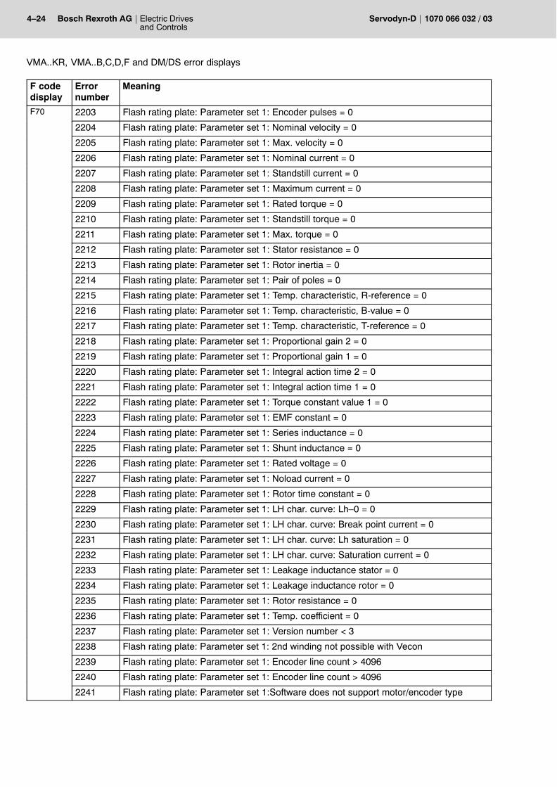
4�24 Electric Drivesand Controls
Bosch Rexroth AG Servodyn-D 1070 066 032 / 03
VMA..KR, VMA..B,C,D,F and DM/DS error displays
F codedisplay
MeaningErrornumber
F70 2203 Flash rating plate: Parameter set 1: Encoder pulses = 0
2204 Flash rating plate: Parameter set 1: Nominal velocity = 0
2205 Flash rating plate: Parameter set 1: Max. velocity = 0
2206 Flash rating plate: Parameter set 1: Nominal current = 0
2207 Flash rating plate: Parameter set 1: Standstill current = 0
2208 Flash rating plate: Parameter set 1: Maximum current = 0
2209 Flash rating plate: Parameter set 1: Rated torque = 0
2210 Flash rating plate: Parameter set 1: Standstill torque = 0
2211 Flash rating plate: Parameter set 1: Max. torque = 0
2212 Flash rating plate: Parameter set 1: Stator resistance = 0
2213 Flash rating plate: Parameter set 1: Rotor inertia = 0
2214 Flash rating plate: Parameter set 1: Pair of poles = 0
2215 Flash rating plate: Parameter set 1: Temp. characteristic, R-reference = 0
2216 Flash rating plate: Parameter set 1: Temp. characteristic, B-value = 0
2217 Flash rating plate: Parameter set 1: Temp. characteristic, T-reference = 0
2218 Flash rating plate: Parameter set 1: Proportional gain 2 = 0
2219 Flash rating plate: Parameter set 1: Proportional gain 1 = 0
2220 Flash rating plate: Parameter set 1: Integral action time 2 = 0
2221 Flash rating plate: Parameter set 1: Integral action time 1 = 0
2222 Flash rating plate: Parameter set 1: Torque constant value 1 = 0
2223 Flash rating plate: Parameter set 1: EMF constant = 0
2224 Flash rating plate: Parameter set 1: Series inductance = 0
2225 Flash rating plate: Parameter set 1: Shunt inductance = 0
2226 Flash rating plate: Parameter set 1: Rated voltage = 0
2227 Flash rating plate: Parameter set 1: Noload current = 0
2228 Flash rating plate: Parameter set 1: Rotor time constant = 0
2229 Flash rating plate: Parameter set 1: LH char. curve: Lh�0 = 0
2230 Flash rating plate: Parameter set 1: LH char. curve: Break point current = 0
2231 Flash rating plate: Parameter set 1: LH char. curve: Lh saturation = 0
2232 Flash rating plate: Parameter set 1: LH char. curve: Saturation current = 0
2233 Flash rating plate: Parameter set 1: Leakage inductance stator = 0
2234 Flash rating plate: Parameter set 1: Leakage inductance rotor = 0
2235 Flash rating plate: Parameter set 1: Rotor resistance = 0
2236 Flash rating plate: Parameter set 1: Temp. coefficient = 0
2237 Flash rating plate: Parameter set 1: Version number < 3
2238 Flash rating plate: Parameter set 1: 2nd winding not possible with Vecon
2239 Flash rating plate: Parameter set 1: Encoder line count > 4096
2240 Flash rating plate: Parameter set 1: Encoder line count > 4096
2241 Flash rating plate: Parameter set 1:Software does not support motor/encoder type
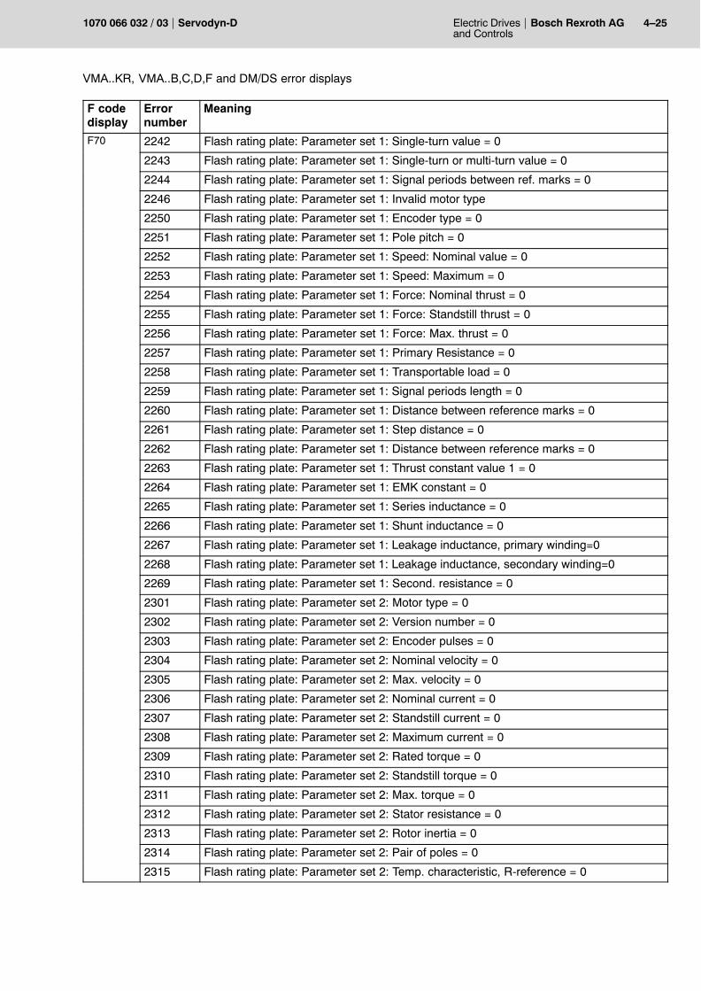
Electric Drivesand Controls
4�25Bosch Rexroth AGServodyn-D1070 066 032 / 03
VMA..KR, VMA..B,C,D,F and DM/DS error displays
F codedisplay
MeaningErrornumber
F70 2242 Flash rating plate: Parameter set 1: Single-turn value = 0
2243 Flash rating plate: Parameter set 1: Single-turn or multi-turn value = 0
2244 Flash rating plate: Parameter set 1: Signal periods between ref. marks = 0
2246 Flash rating plate: Parameter set 1: Invalid motor type
2250 Flash rating plate: Parameter set 1: Encoder type = 0
2251 Flash rating plate: Parameter set 1: Pole pitch = 0
2252 Flash rating plate: Parameter set 1: Speed: Nominal value = 0
2253 Flash rating plate: Parameter set 1: Speed: Maximum = 0
2254 Flash rating plate: Parameter set 1: Force: Nominal thrust = 0
2255 Flash rating plate: Parameter set 1: Force: Standstill thrust = 0
2256 Flash rating plate: Parameter set 1: Force: Max. thrust = 0
2257 Flash rating plate: Parameter set 1: Primary Resistance = 0
2258 Flash rating plate: Parameter set 1: Transportable load = 0
2259 Flash rating plate: Parameter set 1: Signal periods length = 0
2260 Flash rating plate: Parameter set 1: Distance between reference marks = 0
2261 Flash rating plate: Parameter set 1: Step distance = 0
2262 Flash rating plate: Parameter set 1: Distance between reference marks = 0
2263 Flash rating plate: Parameter set 1: Thrust constant value 1 = 0
2264 Flash rating plate: Parameter set 1: EMK constant = 0
2265 Flash rating plate: Parameter set 1: Series inductance = 0
2266 Flash rating plate: Parameter set 1: Shunt inductance = 0
2267 Flash rating plate: Parameter set 1: Leakage inductance, primary winding=0
2268 Flash rating plate: Parameter set 1: Leakage inductance, secondary winding=0
2269 Flash rating plate: Parameter set 1: Second. resistance = 0
2301 Flash rating plate: Parameter set 2: Motor type = 0
2302 Flash rating plate: Parameter set 2: Version number = 0
2303 Flash rating plate: Parameter set 2: Encoder pulses = 0
2304 Flash rating plate: Parameter set 2: Nominal velocity = 0
2305 Flash rating plate: Parameter set 2: Max. velocity = 0
2306 Flash rating plate: Parameter set 2: Nominal current = 0
2307 Flash rating plate: Parameter set 2: Standstill current = 0
2308 Flash rating plate: Parameter set 2: Maximum current = 0
2309 Flash rating plate: Parameter set 2: Rated torque = 0
2310 Flash rating plate: Parameter set 2: Standstill torque = 0
2311 Flash rating plate: Parameter set 2: Max. torque = 0
2312 Flash rating plate: Parameter set 2: Stator resistance = 0
2313 Flash rating plate: Parameter set 2: Rotor inertia = 0
2314 Flash rating plate: Parameter set 2: Pair of poles = 0
2315 Flash rating plate: Parameter set 2: Temp. characteristic, R-reference = 0
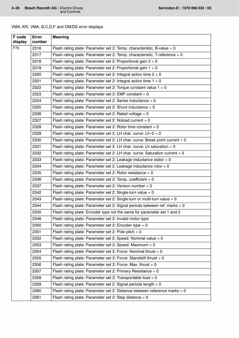
4�26 Electric Drivesand Controls
Bosch Rexroth AG Servodyn-D 1070 066 032 / 03
VMA..KR, VMA..B,C,D,F and DM/DS error displays
F codedisplay
MeaningErrornumber
F70 2316 Flash rating plate: Parameter set 2: Temp. characteristic, B-value = 0
2317 Flash rating plate: Parameter set 2: Temp. characteristic, T-reference = 0
2318 Flash rating plate: Parameter set 2: Proportional gain 2 = 0
2319 Flash rating plate: Parameter set 2: Proportional gain 1 = 0
2320 Flash rating plate: Parameter set 2: Integral action time 2 = 0
2321 Flash rating plate: Parameter set 2: Integral action time 1 = 0
2322 Flash rating plate: Parameter set 2: Torque constant value 1 = 0
2323 Flash rating plate: Parameter set 2: EMF constant = 0
2324 Flash rating plate: Parameter set 2: Series inductance = 0
2325 Flash rating plate: Parameter set 2: Shunt inductance = 0
2326 Flash rating plate: Parameter set 2: Rated voltage = 0
2327 Flash rating plate: Parameter set 2: Noload current = 0
2328 Flash rating plate: Parameter set 2: Rotor time constant = 0
2329 Flash rating plate: Parameter set 2: LH char. curve: Lh�0 = 0
2330 Flash rating plate: Parameter set 2: LH char. curve: Break point current = 0
2331 Flash rating plate: Parameter set 2: LH char. curve: Lh saturation = 0
2332 Flash rating plate: Parameter set 2: LH char. curve: Saturation current = 0
2333 Flash rating plate: Parameter set 2: Leakage inductance stator = 0
2334 Flash rating plate: Parameter set 2: Leakage inductance rotor = 0
2335 Flash rating plate: Parameter set 2: Rotor resistance = 0
2336 Flash rating plate: Parameter set 2: Temp. coefficient = 0
2337 Flash rating plate: Parameter set 2: Version number < 3
2342 Flash rating plate: Parameter set 2: Single-turn value = 0
2343 Flash rating plate: Parameter set 2: Single-turn or multi-turn value = 0
2344 Flash rating plate: Parameter set 2: Signal periods between ref. marks = 0
2345 Flash rating plate: Encoder type not the same for parameter set 1 and 2
2346 Flash rating plate: Parameter set 2: Invalid motor type
2350 Flash rating plate: Parameter set 2: Encoder type = 0
2351 Flash rating plate: Parameter set 2: Pole pitch = 0
2352 Flash rating plate: Parameter set 2: Speed: Nominal value = 0
2353 Flash rating plate: Parameter set 2: Speed: Maximum = 0
2354 Flash rating plate: Parameter set 2: Force: Nominal thrust = 0
2355 Flash rating plate: Parameter set 2: Force: Standstill thrust = 0
2356 Flash rating plate: Parameter set 2: Force: Max. thrust = 0
2357 Flash rating plate: Parameter set 2: Primary Resistance = 0
2358 Flash rating plate: Parameter set 2: Transportable load = 0
2359 Flash rating plate: Parameter set 2: Signal periods length = 0
2360 Flash rating plate: Parameter set 2: Distance between reference marks = 0
2361 Flash rating plate: Parameter set 2: Step distance = 0
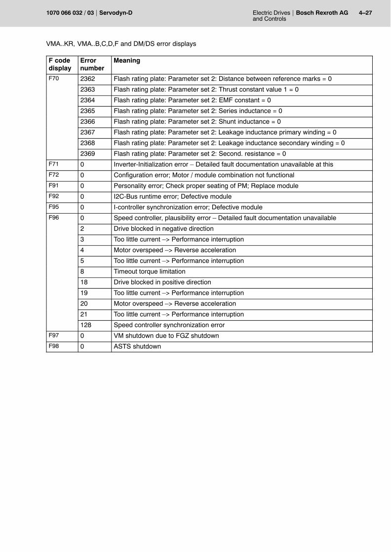
Electric Drivesand Controls
4�27Bosch Rexroth AGServodyn-D1070 066 032 / 03
VMA..KR, VMA..B,C,D,F and DM/DS error displays
F codedisplay
MeaningErrornumber
F70 2362 Flash rating plate: Parameter set 2: Distance between reference marks = 0
2363 Flash rating plate: Parameter set 2: Thrust constant value 1 = 0
2364 Flash rating plate: Parameter set 2: EMF constant = 0
2365 Flash rating plate: Parameter set 2: Series inductance = 0
2366 Flash rating plate: Parameter set 2: Shunt inductance = 0
2367 Flash rating plate: Parameter set 2: Leakage inductance primary winding = 0
2368 Flash rating plate: Parameter set 2: Leakage inductance secondary winding = 0
2369 Flash rating plate: Parameter set 2: Second. resistance = 0
F71 0 Inverter-Initialization error � Detailed fault documentation unavailable at this
F72 0 Configuration error; Motor / module combination not functional
F91 0 Personality error; Check proper seating of PM; Replace module
F92 0 I2C-Bus runtime error; Defective module
F95 0 I-controller synchronization error; Defective module
F96 0 Speed controller, plausibility error � Detailed fault documentation unavailable
2 Drive blocked in negative direction
3 Too little current �> Performance interruption
4 Motor overspeed �> Reverse acceleration
5 Too little current �> Performance interruption
8 Timeout torque limitation
18 Drive blocked in positive direction
19 Too little current �> Performance interruption
20 Motor overspeed �> Reverse acceleration
21 Too little current �> Performance interruption
128 Speed controller synchronization error
F97 0 VM shutdown due to FGZ shutdown
F98 0 ASTS shutdown
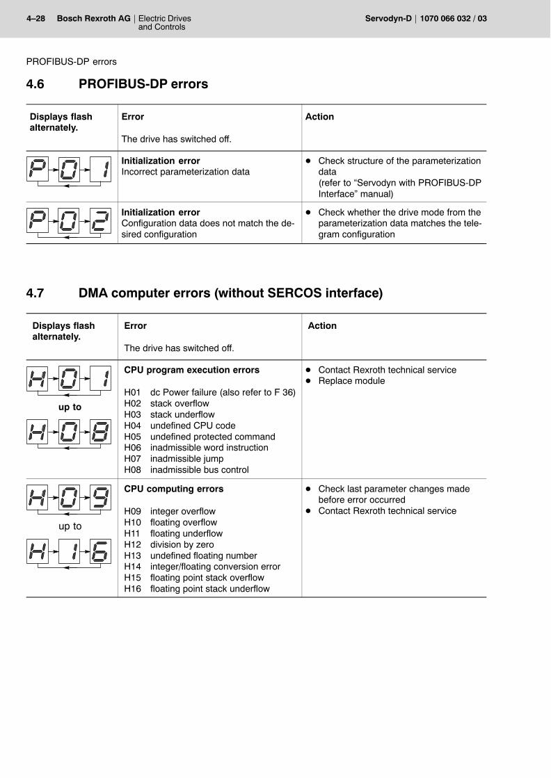
4�28 Electric Drivesand Controls
Bosch Rexroth AG Servodyn-D 1070 066 032 / 03
PROFIBUS-DP errors
4.6 PROFIBUS-DP errors
Displays flashalternately.
Error
The drive has switched off.
Action
Initialization errorIncorrect parameterization data
D Check structure of the parameterizationdata(refer to �Servodyn with PROFIBUS-DPInterface� manual)
Initialization errorConfiguration data does not match the de-sired configuration
D Check whether the drive mode from theparameterization data matches the tele-gram configuration
4.7 DMA computer errors (without SERCOS interface)
Displays flash alternately.
Error
The drive has switched off.
Action
up to
CPU program execution errors
H01 dc Power failure (also refer to F 36)H02 stack overflowH03 stack underflowH04 undefined CPU codeH05 undefined protected commandH06 inadmissible word instructionH07 inadmissible jumpH08 inadmissible bus control
D Contact Rexroth technical serviceD Replace module
up to
CPU computing errors
H09 integer overflowH10 floating overflowH11 floating underflowH12 division by zeroH13 undefined floating numberH14 integer/floating conversion errorH15 floating point stack overflowH16 floating point stack underflow
D Check last parameter changes madebefore error occurred
D Contact Rexroth technical service
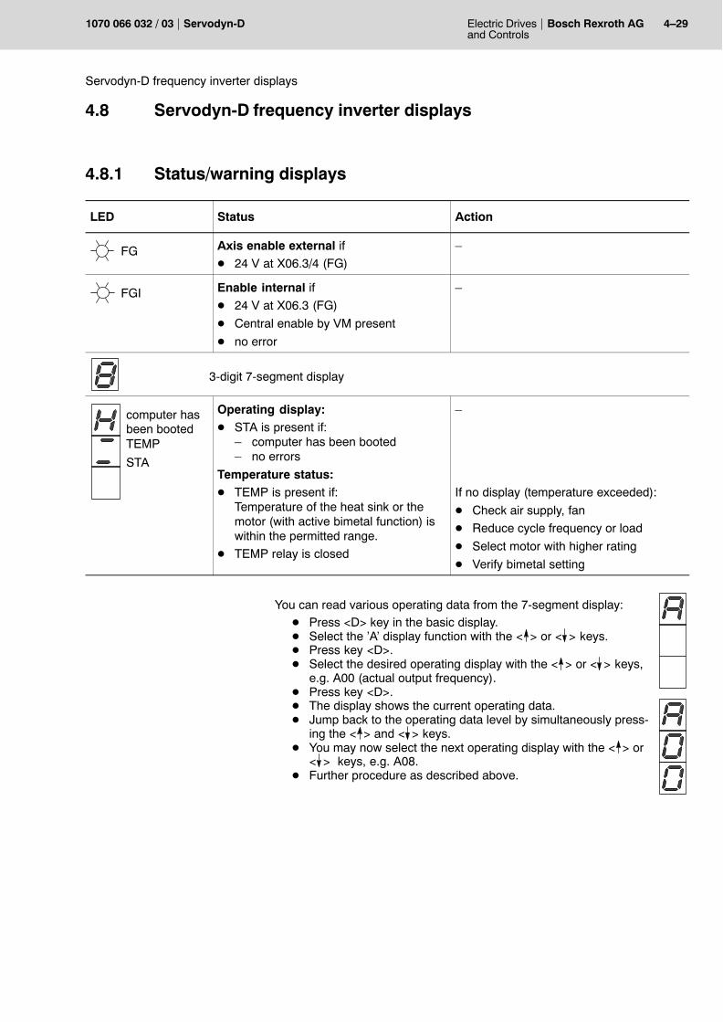
Electric Drivesand Controls
4�29Bosch Rexroth AGServodyn-D1070 066 032 / 03
Servodyn-D frequency inverter displays
4.8 Servodyn-D frequency inverter displays
4.8.1 Status/warning displays
LED Status Action
FG Axis enable external ifD 24 V at X06.3/4 (FG)
�
FGI Enable internal ifD 24 V at X06.3 (FG)
D Central enable by VM present
D no error
�
3-digit 7-segment display
computer hasbeen bootedTEMP
STA
Operating display:D STA is present if:
� computer has been booted� no errors
Temperature status:D TEMP is present if:
Temperature of the heat sink or themotor (with active bimetal function) iswithin the permitted range.
D TEMP relay is closed
�
If no display (temperature exceeded):
D Check air supply, fan
D Reduce cycle frequency or load
D Select motor with higher rating
D Verify bimetal setting
You can read various operating data from the 7-segment display:D Press <D> key in the basic display.D Select the �A� display function with the < > or < > keys.D Press key <D>.D Select the desired operating display with the < > or < > keys,
e.g. A00 (actual output frequency).D Press key <D>.D The display shows the current operating data.D Jump back to the operating data level by simultaneously press-
ing the < > and < > keys.D You may now select the next operating display with the < > or
< > keys, e.g. A08.D Further procedure as described above.
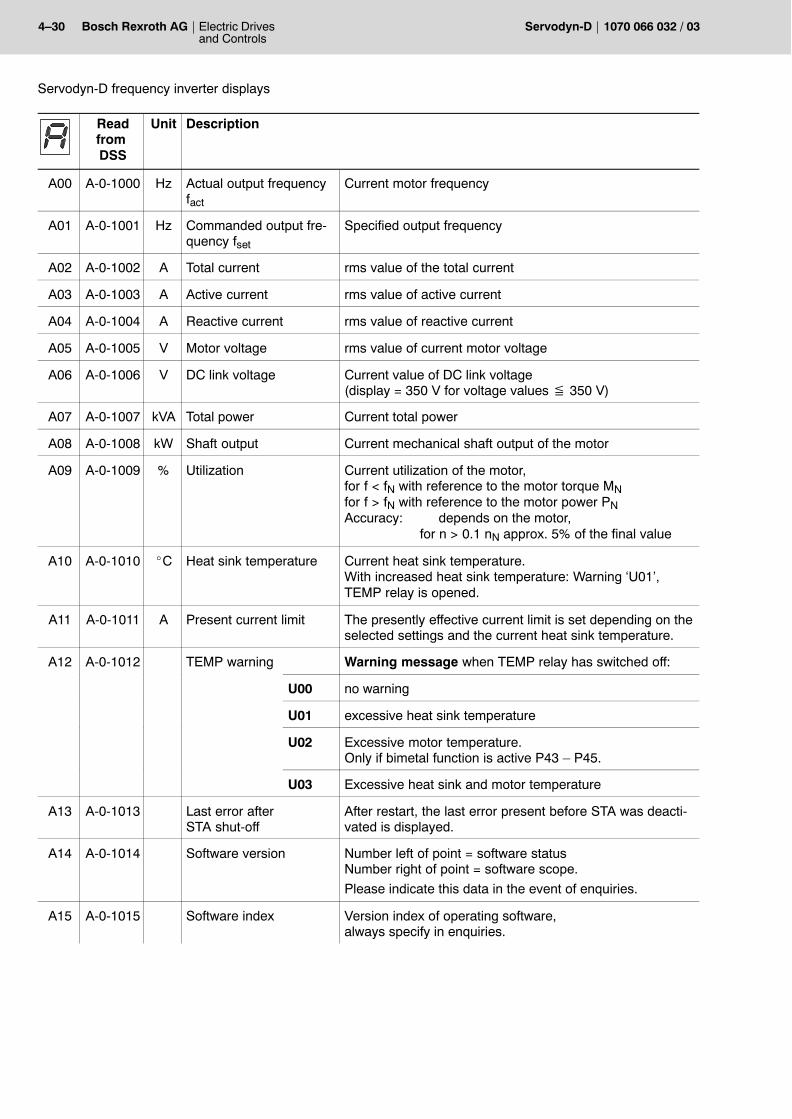
4�30 Electric Drivesand Controls
Bosch Rexroth AG Servodyn-D 1070 066 032 / 03
Servodyn-D frequency inverter displays
Readfrom DSS
Unit Description
A00 A-0-1000 Hz Actual output frequencyfact
Current motor frequency
A01 A-0-1001 Hz Commanded output fre-quency fset
Specified output frequency
A02 A-0-1002 A Total current rms value of the total current
A03 A-0-1003 A Active current rms value of active current
A04 A-0-1004 A Reactive current rms value of reactive current
A05 A-0-1005 V Motor voltage rms value of current motor voltage
A06 A-0-1006 V DC link voltage Current value of DC link voltage(display = 350 V for voltage values � 350 V)
A07 A-0-1007 kVA Total power Current total power
A08 A-0-1008 kW Shaft output Current mechanical shaft output of the motor
A09 A-0-1009 % Utilization Current utilization of the motor,for f < fN with reference to the motor torque MNfor f > fN with reference to the motor power PNAccuracy: depends on the motor,
for n > 0.1 nN approx. 5% of the final value
A10 A-0-1010 _C Heat sink temperature Current heat sink temperature. With increased heat sink temperature: Warning �U01�, TEMP relay is opened.
A11 A-0-1011 A Present current limit The presently effective current limit is set depending on theselected settings and the current heat sink temperature.
A12 A-0-1012 TEMP warning Warning message when TEMP relay has switched off:
U00 no warning
U01 excessive heat sink temperature
U02 Excessive motor temperature.Only if bimetal function is active P43 � P45.
U03 Excessive heat sink and motor temperature
A13 A-0-1013 Last error after STA shut-off
After restart, the last error present before STA was deacti-vated is displayed.
A14 A-0-1014 Software version Number left of point = software statusNumber right of point = software scope.
Please indicate this data in the event of enquiries.
A15 A-0-1015 Software index Version index of operating software, always specify in enquiries.
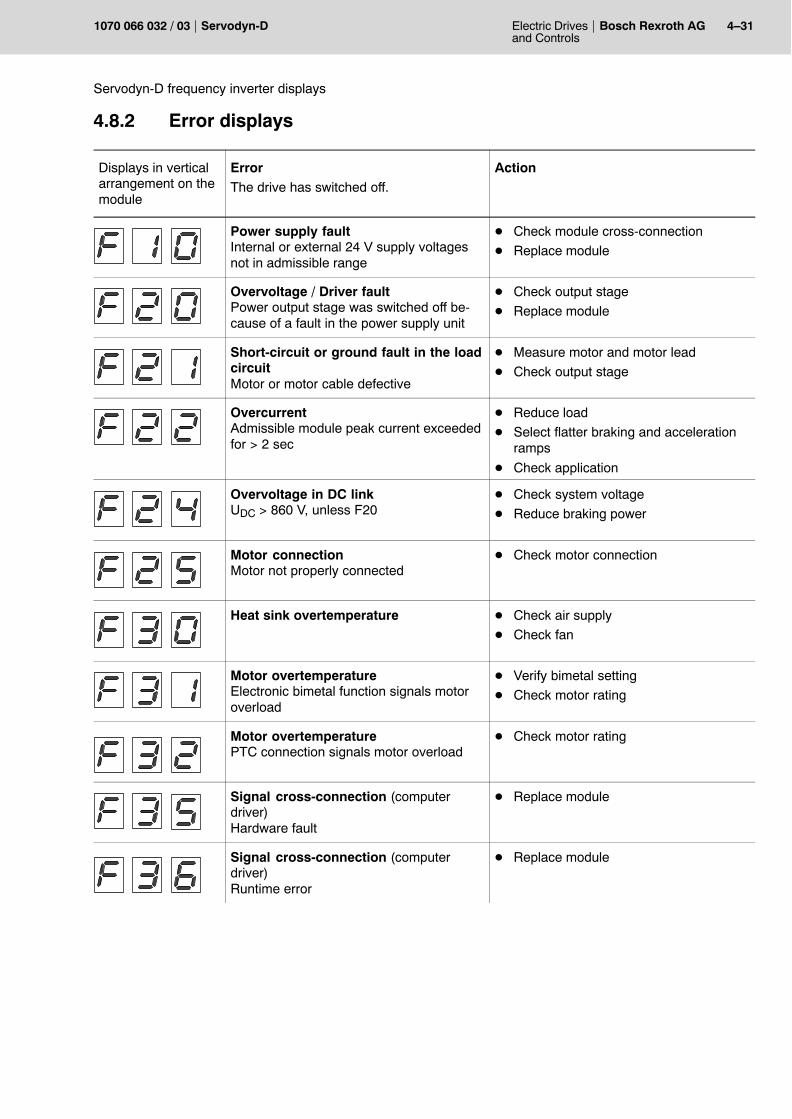
Electric Drivesand Controls
4�31Bosch Rexroth AGServodyn-D1070 066 032 / 03
Servodyn-D frequency inverter displays
4.8.2 Error displays
Displays in verticalarrangement on themodule
ErrorThe drive has switched off.
Action
Power supply faultInternal or external 24 V supply voltagesnot in admissible range
D Check module cross-connection
D Replace module
Overvoltage / Driver faultPower output stage was switched off be-cause of a fault in the power supply unit
D Check output stage
D Replace module
Short-circuit or ground fault in the loadcircuitMotor or motor cable defective
D Measure motor and motor lead
D Check output stage
OvercurrentAdmissible module peak current exceededfor > 2 sec
D Reduce load
D Select flatter braking and accelerationramps
D Check application
Overvoltage in DC linkUDC > 860 V, unless F20
D Check system voltage
D Reduce braking power
Motor connectionMotor not properly connected
D Check motor connection
Heat sink overtemperature D Check air supply
D Check fan
Motor overtemperatureElectronic bimetal function signals motoroverload
D Verify bimetal setting
D Check motor rating
Motor overtemperaturePTC connection signals motor overload
D Check motor rating
Signal cross-connection (computerdriver)Hardware fault
D Replace module
Signal cross-connection (computerdriver)Runtime error
D Replace module
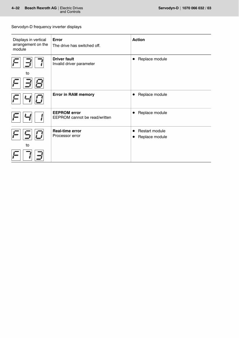
4�32 Electric Drivesand Controls
Bosch Rexroth AG Servodyn-D 1070 066 032 / 03
Servodyn-D frequency inverter displays
Displays in verticalarrangement on themodule
ActionErrorThe drive has switched off.
to
Driver faultInvalid driver parameter
D Replace module
Error in RAM memory D Replace module
EEPROM errorEEPROM cannot be read/written
D Replace module
to
Real-time errorProcessor error
D Restart module
D Replace module
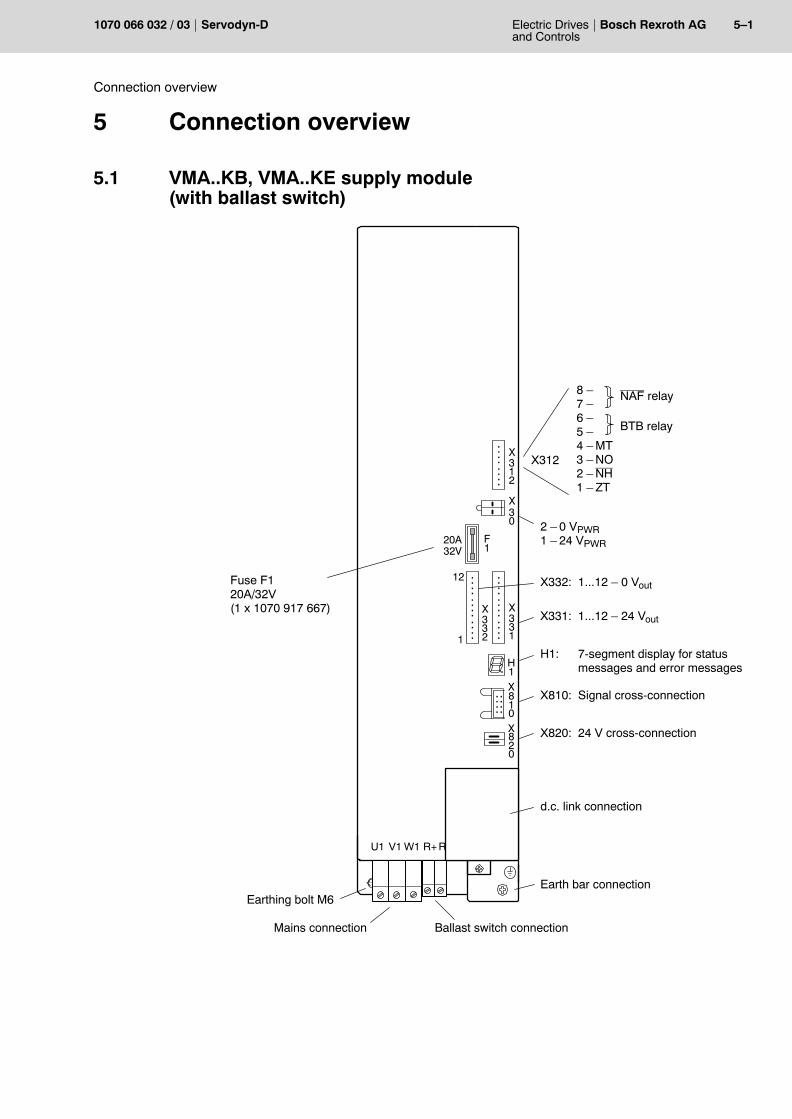
Electric Drivesand Controls
5�1Bosch Rexroth AGServodyn-D1070 066 032 / 03
Connection overview
5 Connection overview
5.1 VMA..KB, VMA..KE supply module(with ballast switch)
X8
U1 V1 W1
..
...... 1
0X820
X810: Signal cross-connection
X820: 24 V cross-connection
X
..
..
..
..312
X........
331..
..X ..
..
..
..
332
..
..
F1
H1: 7-segment display for statusmessages and error messages
X312
NAF relay8 �7 �6 �5 �4 � MT3 � NO2 � NH1 � ZT
X30 2 � 0 VPWR
1 � 24 VPWR
Fuse F120A/32V(1 x 1070 917 667)
Earthing bolt M6Earth bar connection
d.c. link connection
H1
20A32V
1
12
X331: 1...12 � 24 Vout
X332: 1...12 � 0 Vout
BTB relay
Mains connection Ballast switch connection
R+ R
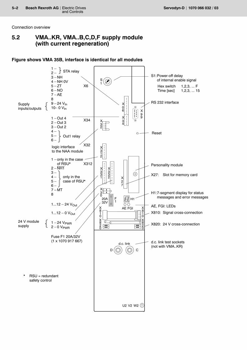
5�2 Electric Drivesand Controls
Bosch Rexroth AG Servodyn-D 1070 066 032 / 03
Connection overview
5.2 VMA..KR, VMA..B,C,D,F supply module(with current regeneration)
Figure shows VMA 35B, interface is identical for all modules
F1
20A32V
.
X8
X0
X34
X99
H1
RS 232 interface
U2 V2 W2
....
..
....
..
..
..
X27
AE FGI
..
...... 1
0X820
Reset
X810: Signal cross-connection
X820: 24 V cross-connection
Personality module
..
.....
X32
X
..
..
..
..312
X........
331
..
..
X........
332
..
..
X81
X820
0
D C
S1
X27: Slot for memory card
H1:7-segment display for statusmessages and error messages
AE, FGI: LEDs
1 �2 �3 � NH4 � NH 0V5 � ZT6 � NO7 � AE89 � 24 VIn10� 0 VIn
1 � Out 42 � Out 33 � Out 24 �5 �6 �
Supplyinputs/outputs
X6
Out1 relay
STA relay
X34
logic interfaceto the NAA module
X32
1 � only in the caseof RSU*
2 � NH13 �4 � only in the5 � case of RSU*6 �7 � MT8
X312
1...12 � 24 VOut
1...12 � 0 VOut
X30
1 � 24 VPWR2 � 0 VPWR
24 V modulesupply
Fuse F1 20A/32V(1 x 1070 917 667)
S1:Power-off delayof internal enable signal
d.c. link test sockets (not with VMA..KR)
* RSU = redundant safety control
6
Hex switch 1,2,3, ... FTime [sec] 1,2,3, ... 15
d.c.�link
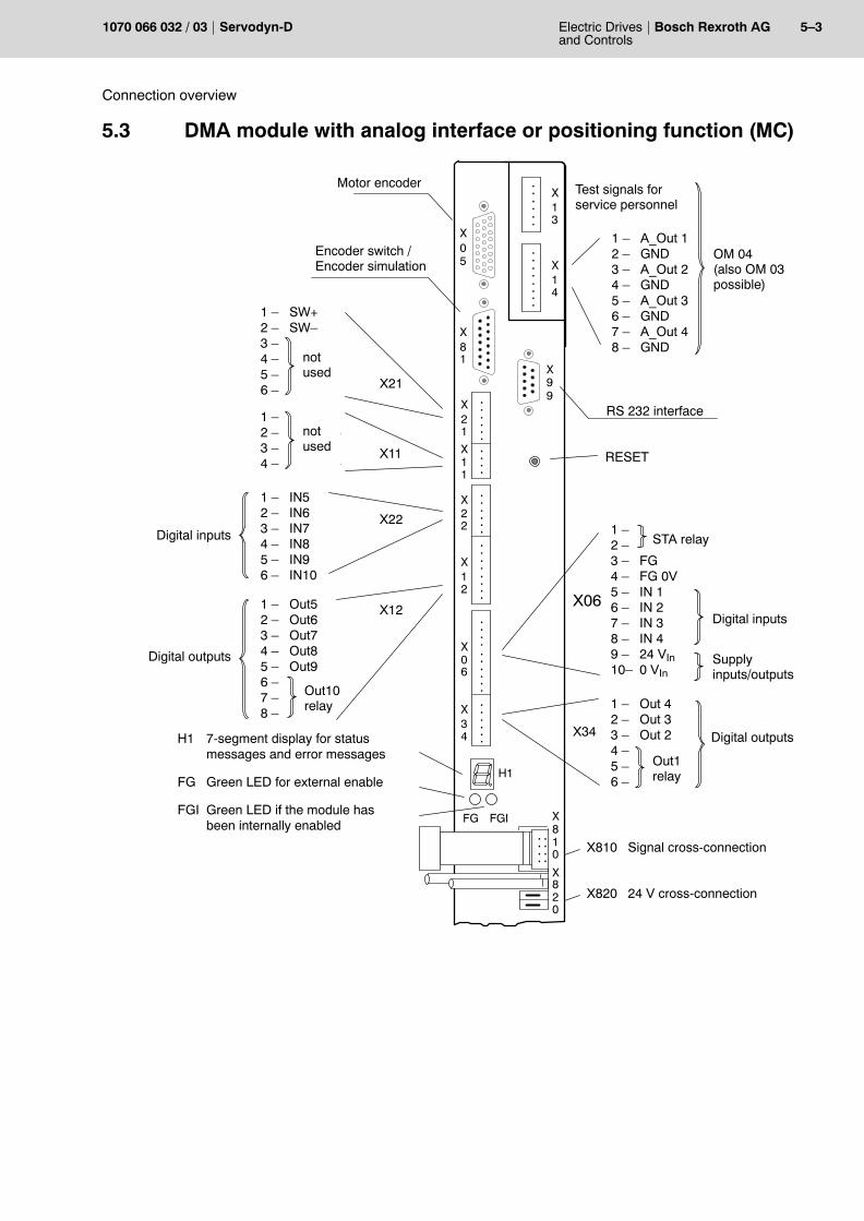
Electric Drivesand Controls
5�3Bosch Rexroth AGServodyn-D1070 066 032 / 03
Connection overview
5.3 DMA module with analog interface or positioning function (MC)
Out10relay
X8
X0
X34
X99
H1
1 � SW+2 � SW�3 � A_IN2+4 � A_IN2�5 � A_IN3+6 � A_IN3�
RS 232 interface
Motor encoder
X0
....
..
....
..
..
..
FG FGI
..
....
.. 10
X820
X21
RESET
X810 Signal cross-connection
X820 24 V cross-connection
H1 7-segment display for status messages and error messages
FG Green LED for external enable
FGI Green LED if the module hasbeen internally enabled
X12
....
....
X22
....
..
X11
....
X21
....
..
6
X81
5
1 � Out 42 � Out 33 � Out 24 �5 �6 �
Out1relay
Digital outputsX34
1 �2 �3 � FG4 � FG 0V5 � IN 16 � IN 27 � IN 38 � IN 49 � 24 VIn10� 0 VIn
STA relay
X06Digital inputs
Supplyinputs/outputs
1 � A_Out1+2 � A_Out1�3 � A_Out2+4 � A_Out2�
X11
1 � IN52 � IN63 � IN74 � IN85 � IN96 � IN10
Digital inputsX22
Encoder switch / Encoder simulation
1 � Out52 � Out63 � Out74 � Out85 � Out96 �7 �8 �
X12
Digital outputs
not used
not used
X14
....
....
..
....X13
1 � A_Out 12 � GND3 � A_Out 24 � GND5 � A_Out 36 � GND7 � A_Out 48 � GND
Test signals forservice personnel
OM 04(also OM 03possible)
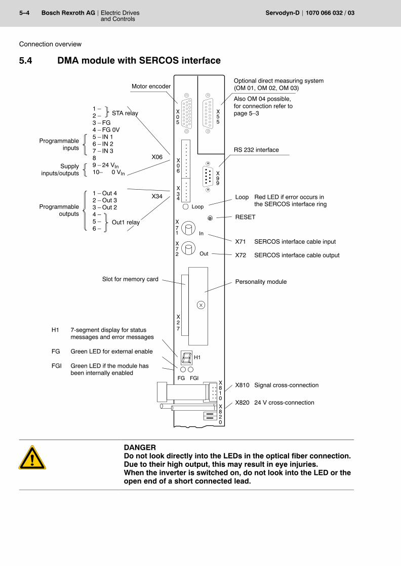
5�4 Electric Drivesand Controls
Bosch Rexroth AG Servodyn-D 1070 066 032 / 03
Connection overview
5.4 DMA module with SERCOS interface
1 �2 �3 � FG4 � FG 0V5 � IN 16 � IN 27 � IN 389 � 24 VIn10� 0 VIn
1 � Out 42 � Out 33 � Out 24 �5 �6 �
Programmableinputs
Supplyinputs/outputs
RS 232 interface
Motor encoder
X06
Out1 relay
STA relay
X34
RESET
X72 SERCOS interface cable output
Loop Red LED if error occurs inthe SERCOS interface ring
X71 SERCOS interface cable input
X810 Signal cross-connection
X820 24 V cross-connection
Personality module
Programmableoutputs
Slot for memory card
H1 7-segment display for status messages and error messages
FG Green LED for external enable
FGI Green LED if the module has been internally enabled
X8
X0
X34
X99
H1
Loop
X0
X55
....
..
....
..
..
..
In
Out
X71
X72
X27
FG FGI
..
....
..10
X820
5
6
Optional direct measuring system(OM 01, OM 02, OM 03)
Also OM 04 possible, for connection refer topage 5�3
DANGERDo not look directly into the LEDs in the optical fiber connection.Due to their high output, this may result in eye injuries.When the inverter is switched on, do not look into the LED or theopen end of a short connected lead.
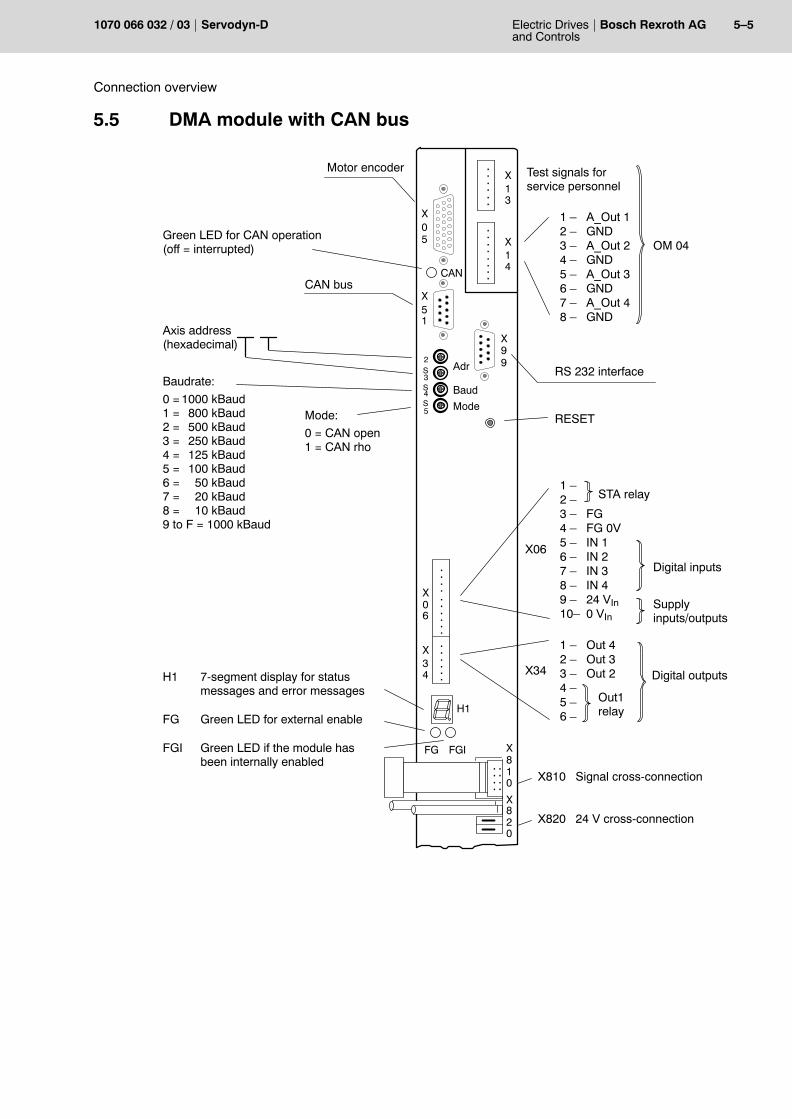
Electric Drivesand Controls
5�5Bosch Rexroth AGServodyn-D1070 066 032 / 03
Connection overview
5.5 DMA module with CAN bus
X8
X0
X34
X99
H1
RS 232 interface
Motor encoder
X0
....
..
....
..
..
..
FG FGI
..
....
.. 10
X820
RESET
X810 Signal cross-connection
X820 24 V cross-connection
H1 7-segment display for status messages and error messages
FG Green LED for external enable
FGI Green LED if the module has been internally enabled
6
5
1 � Out 42 � Out 33 � Out 24 �5 �6 �
Out1relay
Digital outputsX34
1 �2 �3 � FG4 � FG 0V5 � IN 16 � IN 27 � IN 38 � IN 49 � 24 VIn10� 0 VIn
STA relay
X06
Digital inputs
Supplyinputs/outputs
Mode:
0 = CAN open1 = CAN rho
Axis address(hexadecimal)
X51
Baudrate:
0 = 1000 kBaud1 = 800 kBaud2 = 500 kBaud3 = 250 kBaud4 = 125 kBaud5 = 100 kBaud6 = 50 kBaud7 = 20 kBaud8 = 10 kBaud9 to F = 1000 kBaud
CAN busCAN
Adr2
S4S5
S3
Green LED for CAN operation(off = interrupted)
Baud
Mode
X14
....
....
..
....X13
1 � A_Out 12 � GND3 � A_Out 24 � GND5 � A_Out 36 � GND7 � A_Out 48 � GND
Test signals forservice personnel
OM 04
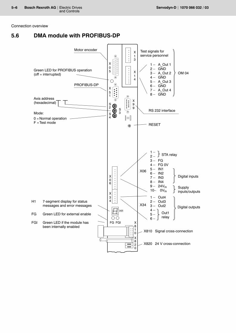
5�6 Electric Drivesand Controls
Bosch Rexroth AG Servodyn-D 1070 066 032 / 03
Connection overview
5.6 DMA module with PROFIBUS-DP
Mode:
0 = Normal operationF =Test mode
X0
X34
X99
H1
Axis address(hexadecimal)
Motor encoder
X0
....
..
....
..
..
..
FG FGI
RESET
H1 7-segment display for status messages and error messages
FG Green LED for external enable
FGI Green LED if the module has been internally enabled
6
X51
5
1 � Out42 � Out33 � Out24 �5 �6 �
Out1relay
Digital outputsX34
1 �2 �3 � FG4 � FG 0V5 � IN16 � IN27 � IN38 � IN49 � 24VIn10� 0VIn
STA relay
X06
Digital inputs
Supplyinputs/outputs
PROFIBUS-DP
S2
S4
S3
Green LED for PROFIBUS operation(off = interrupted)
X8
..
....
.. 10
X820
X810 Signal cross-connection
X820 24 V cross-connection
RS 232 interface
X14
....
....
..
....X13
1 � A_Out 12 � GND3 � A_Out 24 � GND5 � A_Out 36 � GND7 � A_Out 48 � GND
Test signals forservice personnel
OM 04
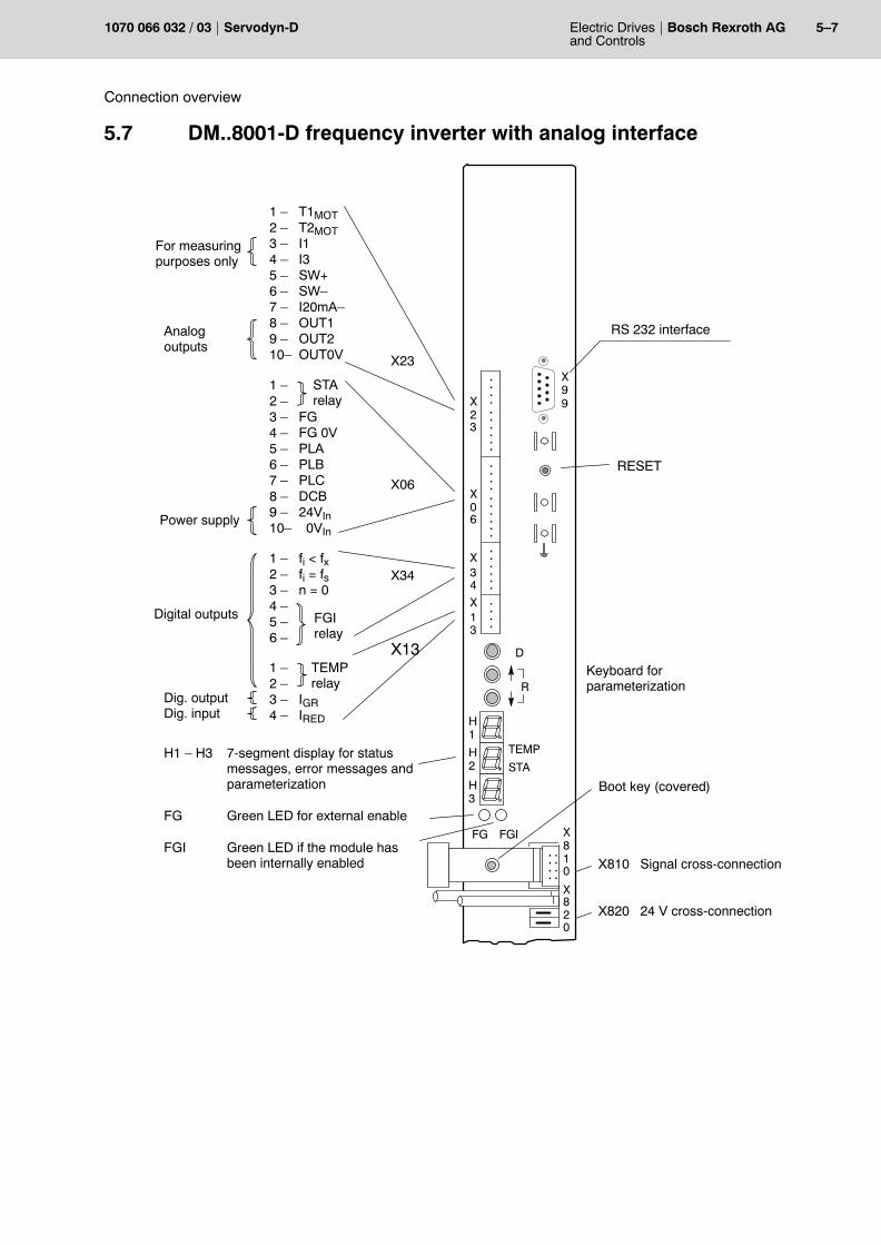
Electric Drivesand Controls
5�7Bosch Rexroth AGServodyn-D1070 066 032 / 03
Connection overview
5.7 DM..8001-D frequency inverter with analog interface
1 �2 �3 � FG4 � FG 0V5 � PLA6 � PLB7 � PLC8 � DCB9 � 24VIn10� 0VIn
1 � fi < fx2 � fi = fs3 � n = 04 �5 �6 �
X8
X0
X34
X99
RS 232 interface
....
..
....
..
..
..
FG FGI
..
....
.. 10
X820
RESET
X810 Signal cross-connection
X820 24 V cross-connection
H1 � H3 7-segment display for status messages, error messages andparameterization
FG Green LED for external enable
FGI Green LED if the module has been internally enabled
6
Digital outputs
STArelay
Power supply
Keyboard for parameterization
X13
..
..
H1
H2
H3
R
D
X23
TEMPrelay
1 � T1MOT2 � T2MOT3 � I14 � I35 � SW+6 � SW�7 � I20mA�8 � OUT19 � OUT210� OUT0V X23
1 �2 �3 � IGR4 � IRED
X34
FGIrelay
X13
X06
Dig. outputDig. input
Analog outputs
TEMP
STA
....
..
..
..
For measuringpurposes only
Boot key (covered)
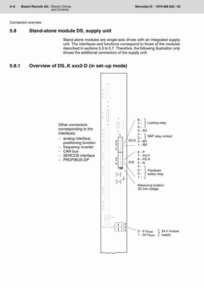
5�8 Electric Drivesand Controls
Bosch Rexroth AG Servodyn-D 1070 066 032 / 03
Connection overview
5.8 Stand-alone module DS, supply unit
Stand-alone modules are single-axis drives with an integrated supplyunit. The interfaces and functions correspond to those of the modulesdescribed in sections 5.3 to 5.7. Therefore, the following illustration onlyshows the additional connectors of the supply unit:
5.8.1 Overview of DS..K xxx2-D (in set�up mode)
X0
X34
X99
H1
X0
....
..
....
..
..
..
FG FGI
X12
....
....
X22
....
..
X11
....
X21
....
..
6
X81
5
X30 2 � 0 VPWR
1 � 24 VPWR
24 V modulesupply
8 �7 �6 �5 � SO4 �3 �2 � MT1 � NH
NAF relay contact
X76
X312
Other connectors corresponding to theinterfaces:� analog interface,
positioning function� frequency inverter� CAN bus� SERCOS interface� PROFIBUS-DP
Measuring location: DC link voltage
8 � P7 � FG P6 � FG N5 � N4 �3 �2 �1 �
....
....
....
....X312
X76
Loading relay
Feedbacksafety relay
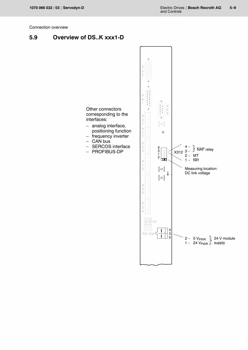
Electric Drivesand Controls
5�9Bosch Rexroth AGServodyn-D1070 066 032 / 03
Connection overview
5.9 Overview of DS..K xxx1-D
X0
X34
X99
H1
X0
....
..
....
..
..
..
FG FGI
X12
....
....
X22
....
..
X11
....
X21
....
..
6
X81
5
....
X30 2 � 0 VPWR
1 � 24 VPWR
24 V modulesupply
4 �3 �2 � MT1 � NH
NAF relayX312
X312
Measuring location: DC link voltage
Other connectors corresponding to theinterfaces:� analog interface,
positioning function� frequency inverter� CAN bus� SERCOS interface� PROFIBUS-DP

5�10 Electric Drivesand Controls
Bosch Rexroth AG Servodyn-D 1070 066 032 / 03
Connection overview
Notes:
Electric Drivesand Controls
6�1Bosch Rexroth AGServodyn-D1070 066 032 / 03
Replacing components
6 Replacing components
DANGERDanger caused by unqualified interventions.The maintenance and installation of the components is reservedto qualified personnel who observes the accident prevention reg-ulations (UVV VBG4, VDE 100, VDE 105) and installation standards(EN 60204-Part 1, prEN 50178).
Please note the safety instructions on the first pages of this manual!
6.1 Motors
DANGERBrakes are subject to wear.The holding brake is no service brake and must only be operatedwhen the axis is at standstill.After approx. 1000 Emergency-Stop braking processes with an ex-traneous moment of inertia � motor moment of inertia, the hold-ing brake must be checked in the manufacturer�s workshop.
DANGEROUS ELECTRICAL VOLTAGEAll connection and installation work must be performed while thesystem is de-energized.Due to permanent magnet excitation, a dangerous voltage is pres-ent at the power outlet when the rotor is rotating and the motor isnot connected electrically!
DANGERDanger of injuries by ejected featherkey.Motors with a groove and featherkey may only be operated wheninstalled in place or with featherkey secured.
CAUTIONDamages to the module or inverter by removing plug-in connec-tions.All plug-in connections to the encoder may only be inserted or re-moved while the drive is switched off.
6�2 Electric Drivesand Controls
Bosch Rexroth AG Servodyn-D 1070 066 032 / 03
Replacing components
CAUTIONImpacts and shocks applied to the shaft end will damage the rotaryencoder and ball bearings!Drive elements such as pulleys, clutch disks, toothed wheels etc.may only be assembled or removed by continuously heating upthe drive elements or with a suitable installation or removal tool.Use the thread in the shaft end.
At least half of motors with an oil-tight flange on the output side (oil-running tight, designs 100, 101) must be submerged in oil. Due to thehigh friction, they must never be started dry. For dry operation, the rotary shaft seal must be removed, however, itcannot be reinstalled afterwards.
CAUTIONLoss of data!Interventions in the motor may delete the data of the electronic rat-ing plate. Do not dismantle servo motors. Installation work in excess of theadjustment of the outgoing cable direction must be performed inthe manufacturer�s workshop.
The outgoing direction of all plug-in systems can be changed by releas-ing the angle flange box. Do not turn the angle flange box by more than 180_ in order to avoiddamaging the connection leads.
CAUTIONMoisture inside the motor.When tightening the angle flange box, please make sure that theO-ring is properly seated in the groove of the angle flange box.Protection standard IP 67 is achieved for the plug-in system onlyif the admissible external lead diameters are maintained and themating connectors are screwed down to their stop.
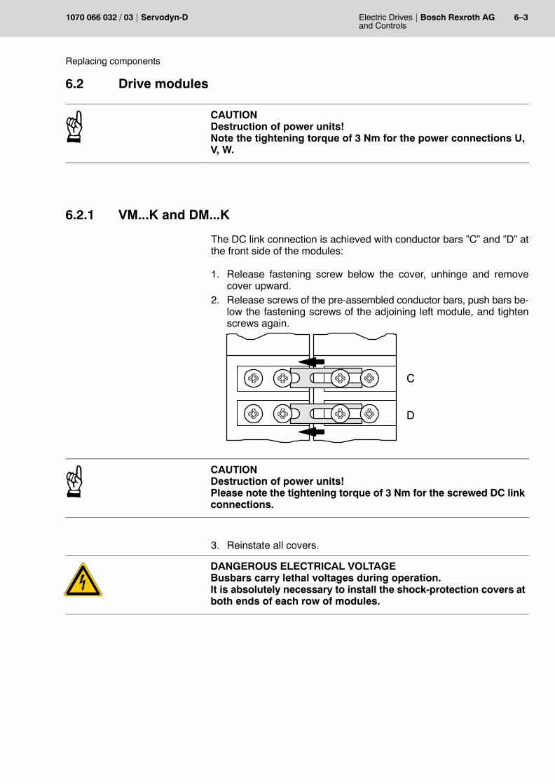
Electric Drivesand Controls
6�3Bosch Rexroth AGServodyn-D1070 066 032 / 03
Replacing components
6.2 Drive modules
CAUTIONDestruction of power units!Note the tightening torque of 3 Nm for the power connections U,V, W.
6.2.1 VM...K and DM...K
The DC link connection is achieved with conductor bars �C� and �D� atthe front side of the modules:
1. Release fastening screw below the cover, unhinge and removecover upward.
2. Release screws of the pre-assembled conductor bars, push bars be-low the fastening screws of the adjoining left module, and tightenscrews again.
C
D
CAUTIONDestruction of power units!Please note the tightening torque of 3 Nm for the screwed DC linkconnections.
3. Reinstate all covers.
DANGEROUS ELECTRICAL VOLTAGEBusbars carry lethal voltages during operation.It is absolutely necessary to install the shock-protection covers atboth ends of each row of modules.
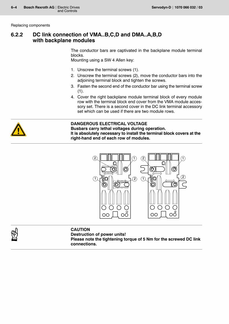
6�4 Electric Drivesand Controls
Bosch Rexroth AG Servodyn-D 1070 066 032 / 03
Replacing components
6.2.2 DC link connection of VMA..B,C,D and DMA..A,B,Dwith backplane modules
The conductor bars are captivated in the backplane module terminalblocks.Mounting using a SW 4 Allen key:
1. Unscrew the terminal screws (1).2. Unscrew the terminal screws (2), move the conductor bars into the
adjoining terminal block and tighten the screws.3. Fasten the second end of the conductor bar using the terminal screw
(1).4. Cover the right backplane module terminal block of every module
row with the terminal block end cover from the VMA module acces-sory set. There is a second cover in the DC link terminal accessoryset which can be used if there are two module rows.
DANGEROUS ELECTRICAL VOLTAGEBusbars carry lethal voltages during operation.It is absolutely necessary to install the terminal block covers at theright-hand end of each row of modules.
D6Nm
C2 1 2 1
1 2 1 2D6Nm
C
CAUTIONDestruction of power units!Please note the tightening torque of 5 Nm for the screwed DC linkconnections.
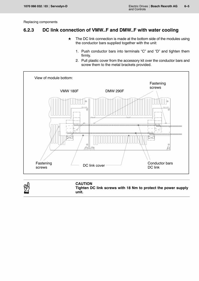
Electric Drivesand Controls
6�5Bosch Rexroth AGServodyn-D1070 066 032 / 03
Replacing components
6.2.3 DC link connection of VMW..F and DMW..F with water cooling
L The DC link connection is made at the bottom side of the modules usingthe conductor bars supplied together with the unit:
1. Push conductor bars into terminals �C� and �D� and tighten themfirmly.
2. Pull plastic cover from the accessory kit over the conductor bars andscrew them to the metal brackets provided.
Conductor barsDC linkDC link cover
Fasteningscrews
Fasteningscrews
VMW 180F DMW 290F
View of module bottom:
CAUTIONTighten DC link screws with 18 Nm to protect the power supplyunit.

6�6 Electric Drivesand Controls
Bosch Rexroth AG Servodyn-D 1070 066 032 / 03
Replacing components
Notes:
Electric Drivesand Controls
A�1Bosch Rexroth AGServodyn-D1070 066 032 / 03
Annex
A Annex
A.1 Index
CComputer errors, 4�28Connection overview
DMA with analog interface, 5�3DMA with CAN bus, 5�5DMA with positioning function (MC), 5�3DMA with PROFIBUS�DP, 5�6DMA with SERCOS interface, 5�4Frequency inverter with analog interface, 5�7Stand�alone module DS, 5�8VMA..B,C,D,F supply modules, 5�2VMA..K supply modules, 5�1VMA..KR supply modules, 5�2
DDC link connection
compact mechanics without backplane module,6�3
with backplane modules, 6�4with water cooling, 6�5
Documentation, 1�9
EEarth�leakage circuit�breaker, 2�3Earthing, 2�1EMC Directive, 1�1, 3�1EMC product standard, 1�1EMERGENCY�STOP devices, 1�6Error displays
all without frequency inverter, 4�5Computer errors, 4�28�4�32Frequency inverter, 4�31PROFIBUS errors, 4�28VMA..KB, VMA..KE supply modules, 4�1
Error numbers P�0�0095, 4�14ESD
Electrostatic discharge, 1�8grounding, 1�8workplace, 1�8
ESD�sensitive components, 1�8EU design type certification, 3�2
FFloppy disk drive, 1�9
GGrounding bracelet, 1�8
HHard disk drive, 1�9Holding brake, 6�1
IIT protective system, 2�1
LLow�Voltage Directive, 1�1, 3�1
MMachinery Directive, 3�1Machinery directive, 1�2Mains connection, 2�1Modules sensitive to electrostatic discharge. See
ESD�sensitive components
PPROFIBUS errors, 4�28
QQualified personnel, 1�3
RRelease, 1�10Replacing components
Drive modules, 6�3Motors, 6�1
RSU, 3�2RSU, redundant safety monitoring, 3�2
SSafety instructions, 1�5Safety markings, 1�4Spare parts, 1�7Standard operation, 1�1Status displays
Frequency inverter, 4�29Stand�alone module DS, 4�4Three�phase modules DM, 4�4VMA..KB, VMA..KE supply modules, 4�1VMA..KR, VMA..B,C,D,F supply modules, 4�2
Supply modules VMA..K, Connection overview, 5�1
TTest activities, 1�7
A�2 Electric Drivesand Controls
Bosch Rexroth AG Servodyn-D 1070 066 032 / 03
Annex
Tightening torqueDC link in backplane modules, 6�4DC link in compact mechanics, 6�3Power connection, 6�3
Trademarks, 1�10
UUL/CSA certification, 3�3
installation and operation, 3�3
WWarnings
Frequency inverter, 4�29VMA..KB, VMA..KE supply modules, 4�1VMA..KR, VMA..B,C,D,F, 4�3
Electric Drivesand Controls
A�1Bosch Rexroth AGServodyn-D1070 066 032 / 03
Bosch Rexroth AGElectric Drives and ControlsBgm.-Dr.-Nebel-Str. 297816 Lohr a. Main, [email protected]
Printed in GermanyDOK-SERV*D-DIAGNOSTICS-WA03-EN-P