Embed Size (px)
Citation preview

100160
Application Note
Servo Press Kit YJKP - Integration of host function blocks in Allen Bradley (Studio 5000 Logix Designer V26.01)
This application note describes how you integrate the host func-tion blocks of the servo press kit YJKP in Allen Bradley (Studio 5000 Logix Designer V26.01).
Supported systems:
- Tested with CompactLogix (1769-L24ER-QB1B)
- All compatible devices
YJKP

Title ............. Servo Press Kit YJKP - Integration of host function blocks in Allen Bradley (Studio 5000 Logix Designer V26.01)
Version ............................................................................................................................................................. 1.10
Document no. .............................................................................................................................................. 100160
Original .................................................................................................................................................................en
Author ............................................................................................................................................................. Festo
Last saved ............................................................................................................................................ 17.11.2017
Copyright Notice This documentation is the intellectual property of Festo AG & Co. KG, which also has the exclusive copyright. Any modification of the content, duplication or reprinting of this documentation as well as distribution to third par-ties can only be made with the express consent of Festo AG & Co. KG.
Festo AG & Co KG reserves the right to make modifications to this document in whole or in part. All brand and product names are trademarks or registered trademarks of their respective owners.
Legal Notice Hardware, software, operating systems and drivers may only be used for the applications described and only in conjunction with components recommended by Festo AG & Co. KG.
Festo AG & Co. KG does not accept any liability for damages arising from the use of any incorrect or incomplete information contained in this documentation or any information missing therefrom.
Defects resulting from the improper handling of devices and modules are excluded from the warranty.
The data and information specified in this document should not be used for the implementation of safety func-tions relating to the protection of personnel and machinery.
No liability is accepted for claims for damages arising from a failure or functional defect. In other respects, the regulations with regard to liability from the terms and conditions of delivery, payment and use of software of Festo AG & Co. KG, which can be found at www.festo.com and can be supplied on request, shall apply.
All data contained in this document do not represent guaranteed specifications, particularly with regard to func-tionality, condition or quality, in the legal sense.
The information in this document serves only as basic information for the implementation of a specific, hypo-thetical application and is in no way intended as a substitute for the operating instructions of the respective manufacturers and the design and testing of the respective application by the user.
The operating instructions for Festo products can be found at www.festo.com/sp .
Users of this document (application note) must verify that all functions described here also work correctly in the application. By reading this document and adhering to the specifications contained therein, users are also solely responsible for their own application.
(Festo AG & CO. KG, D-73726 Esslingen, 2017) Internet: http://www.festo.com E-Mail: [email protected]

Application Note – Servo Press Kit YJKP - Integration of host function blocks in Allen Bradley (Studio 5000 Logix Designer V26.01)
Table of contents
1 Components/Software used ....................................................................................................................... 4
2 Application description ............................................................................................................................... 5
3 Device setup in Studio 5000 (Logix Designer V26.01) ............................................................................... 6
3.1 Adding the controller (CECC-X1-M1) of the YJKP to devices & networks ...................................................... 6
3.2 Importing the Add-On Instructions ............................................................................................................ 11
3.3 Set up a function block .............................................................................................................................. 14

Components/Software used
Seite 4 von 18 Application Note – Servo Press Kit YJKP - Integration of host function blocks in Allen Bradley (Studio 5000 Logix Designer V26.01) – 1.00
1 Components/Software used
Type/Name Version Software/Firmware Date of manufacture
Servo press kit YJKP general --
Application software YJKP (GSAY-A4-F0-Z4-1.2.1) V1.2.1 --
Firmware controller (CECC-X) V3.4.6 --
Firmware motor controller (CMMP-AS) V4.0.1501.2.4 --
Allen Bradley (Studio 5000 Logix Designer) V26.01 --
Table 1.1: 1 Components/Software used

Application description
Application Note – Servo Press Kit YJKP - Integration of host function blocks in Allen Bradley (Studio 5000 Logix Designer V26.01) – 1.00 Seite 5 von 18
2 Application description
This application note describes how you integrate the host function blocks of the servo press kit YJKP in Allen Bradley (Studio 5000 Logix Designer V26.01).
Supported systems:
• Tested with CompactLogix (1769-L24ER-QB1B) • All compatible devices
Supported fieldbus:
• EtherNet/IP
Following descriptions are part of the application note:
• Device setup in Studio 5000 (Logix Designer V26.01) o Adding the controller (CECC-X1-M1) of the YJKP to devices & networks o Importing the Add-On Instructions o Set up a function block
Content of the download package:
• Link to the Application Notes • Example • Source code
Device setup in Studio 5000 (Logix Designer V26.01)
Seite 6 von 18 Application Note – Servo Press Kit YJKP - Integration of host function blocks in Allen Bradley (Studio 5000 Logix Designer V26.01) – 1.00
3 Device setup in Studio 5000 (Logix Designer V26.01)
3.1 Adding the controller (CECC-X1-M1) of the YJKP to devices & networks
No. Action
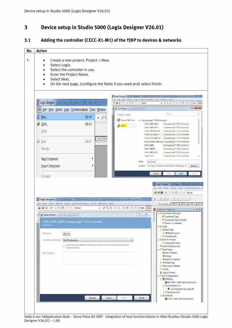
1.
• Create a new project: Project -> New. • Select Logix. • Select the controller in use. • Enter the Project Name. • Select Next. • On the next page, (configure the fields if you need and) select Finish.
Device setup in Studio 5000 (Logix Designer V26.01)
Application Note – Servo Press Kit YJKP - Integration of host function blocks in Allen Bradley (Studio 5000 Logix Designer V26.01) – 1.00 Seite 7 von 18
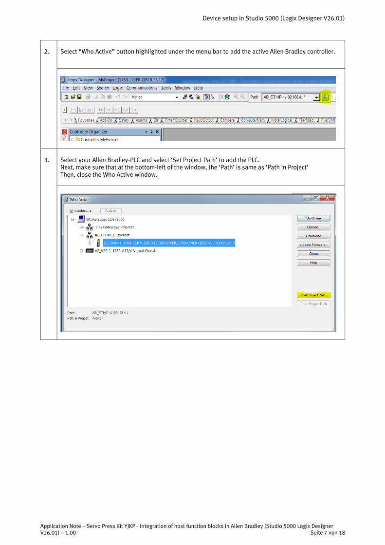
2.
Select “Who Active” button highlighted under the menu bar to add the active Allen Bradley controller.
3.
Select your Allen Bradley-PLC and select ‘Set Project Path‘ to add the PLC. Next, make sure that at the bottom-left of the window, the ‘Path’ is same as ‘Path in Project’ Then, close the Who Active window.
Device setup in Studio 5000 (Logix Designer V26.01)
Seite 8 von 18 Application Note – Servo Press Kit YJKP - Integration of host function blocks in Allen Bradley (Studio 5000 Logix Designer V26.01) – 1.00
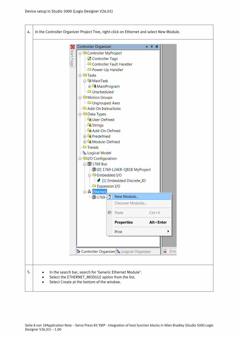
4.
In the Controller Organizer Project Tree, right-click on Ethernet and select New Module.
5.
• In the search bar, search for ‘Generic Ethernet Module’. • Select the ETHERNET_MODULE option from the list. • Select Create at the bottom of the window.

Device setup in Studio 5000 (Logix Designer V26.01)
Application Note – Servo Press Kit YJKP - Integration of host function blocks in Allen Bradley (Studio 5000 Logix Designer V26.01) – 1.00 Seite 9 von 18
6.
• In the New Module window, set the Name and IP Address of your CECC-X-M1 system and set the
Comm. Format and the Connection Parameters as shown in the images below and select OK. • Finally, close all the other open windows.

Device setup in Studio 5000 (Logix Designer V26.01)
Seite 10 von 18 Application Note – Servo Press Kit YJKP - Integration of host function blocks in Allen Bradley (Studio 5000 Logix Designer V26.01) – 1.00
7.
A new Ethernet Module for the CECC-X-M1 should be created as shown below.
Table 3-1: Adding the controller (CECC-X1-M1) of the YJKP to devices & networks
Device setup in Studio 5000 (Logix Designer V26.01)
Application Note – Servo Press Kit YJKP - Integration of host function blocks in Allen Bradley (Studio 5000 Logix Designer V26.01) – 1.00 Seite 11 von 18
3.2 Importing the Add-On Instructions
No. Action
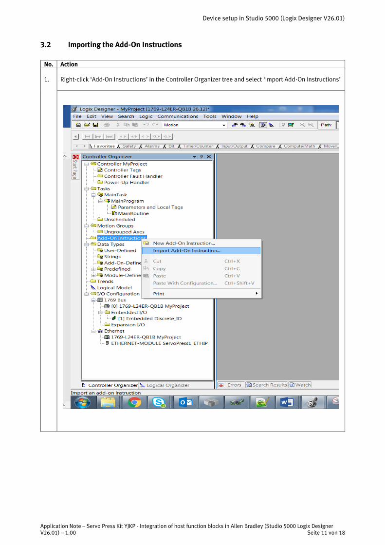
1.
Right-click ‘Add-On Instructions’ in the Controller Organizer tree and select ‘Import Add-On Instructions’

Device setup in Studio 5000 (Logix Designer V26.01)
Seite 12 von 18 Application Note – Servo Press Kit YJKP - Integration of host function blocks in Allen Bradley (Studio 5000 Logix Designer V26.01) – 1.00
2.
Select the following Add-On Instruction export (.L5X) file from the zip folder downloaded from the Support Portal and click OK. Select OK for the next window as well.

Device setup in Studio 5000 (Logix Designer V26.01)
Application Note – Servo Press Kit YJKP - Integration of host function blocks in Allen Bradley (Studio 5000 Logix Designer V26.01) – 1.00 Seite 13 von 18
4.
Notice that the Add-On Instructions and all the supporting User-defined Data types will be imported into the Controller Organizer tree view under -
• Add-On Instructions, and • Data Types / User-Defined

Device setup in Studio 5000 (Logix Designer V26.01)
Seite 14 von 18 Application Note – Servo Press Kit YJKP - Integration of host function blocks in Allen Bradley (Studio 5000 Logix Designer V26.01) – 1.00
3.3 Set up a function block
Caution
This implementation of the function blocks is only an example! Please implement it according to your own standard!
No.
Action
1.
• Create a new function block instance for all the Function Blocks (also referred to as Add-On In-
structions) with the name of your choice and assign the data type as shown below. In this ex-ample it is a function block with the name “FBConnect” as an instance of “FB_Connect” func-tion block and so on for all the other AOIs as well.
• Create a new variable of the structure “ST_SystemDataRef” with the name of your choice. In this example the name is “stSystemDataRef”. This data structure contains all data required to communicate with the YJKP and represents one instance of the YJKP.
• Also, create a new variable of the Type INT with the name of your choice. In this example, the name is “ModuleStatus”. This variable will be assigned the value of the connection status be-tween the Allen Bradley PLC and the CECC-X-M1 system and will be used for Comm. status check in the Main Task.
• The ServoPress1_ETHIP:I.Data, ServoPress1_ETHIP:O.Data and ServoPress1_ETHIP:C variables are respectively the Input Data Stream received by the AB PLC, Output Data Stream sent by the AB PLC and Configuration Data stream (not being used) which will be assigned to the FB_MapInputData and FB_MapOutputData Function blocks as will be shown in a few steps.
2.
Set the value of the connection timeout on the first rung as shown below. Create a timeout variable of your choice (Source A) and use the MUL instruction to multiply with Source B which in this case is 1000 milliseconds (1 sec) and assign its value to stSystemDataRef.stConnectionSettings.tTimeout (Dest).

Device setup in Studio 5000 (Logix Designer V26.01)
Application Note – Servo Press Kit YJKP - Integration of host function blocks in Allen Bradley (Studio 5000 Logix Designer V26.01) – 1.00 Seite 15 von 18
3.
On the next rung, create the FB_MapInputData instruction by dragging the function block from the Add-On selection onto the rung and assign the FB_MapInputData, stSystemDataRef and asiInputData ( Servo-Press1_ETHIP:I.Data in this example) instances as inputs, as shown below. Note: It is good practice to call FB_MapInputData before all the other Function Block calls.
4.
Next, add the FB_Connect function block in the following manner.
• Use the GSV (Get System Value) instruction to check the status of the connection with the values as shown below. The Instance Name is the name assigned to the Generic Ethernet Module.
• Use the EQU (Equals) instruction to check if the connection with the Generic Ethernet Module is established (16#4000) and use that to set the value of stSystemDataRef.xStatusOfConnection.
• Create an alternate rung around the StatusOfConnection check block with NOP (No Operation) in order to call the FB_Connect function block even when connection is not established. Otherwise, FB_Connect can also be called on the next rung independently to avoid the NOP instruction.
• Create the FB_Connect instruction by dragging the function block from the Add-On selection onto the rung and assign the FB_Connect and stSystemDataRef instances as inputs.

Device setup in Studio 5000 (Logix Designer V26.01)
Seite 16 von 18 Application Note – Servo Press Kit YJKP - Integration of host function blocks in Allen Bradley (Studio 5000 Logix Designer V26.01) – 1.00
5.
Create instances of asiDataToBeWritten and asiReadData of type SINT[76] (Array of SINT – length 76). To create the FB_ReadWriteObject instruction, drag the function block from the Add-On selection onto the next rung and assign the FB_ ReadWriteObject, stSystemDataRef, asiDataToBeWritten and asiRead-Data instances as inputs, as shown below.
6.
To create the FB_ Manual instruction, on the next rung, drag the function block from the Add-On selec-tion onto the rung and assign the FB_Manual and stSystemDataRef instances as inputs, as shown be-low.

Device setup in Studio 5000 (Logix Designer V26.01)
Application Note – Servo Press Kit YJKP - Integration of host function blocks in Allen Bradley (Studio 5000 Logix Designer V26.01) – 1.00 Seite 17 von 18
7.
To create the FB_PressControl instruction, on the next rung, drag the function block from the Add-On selection onto the rung and assign the FB_PressControl and stSystemDataRef instances as inputs, as shown below.
8.
To create the FB_Status instruction, on the next rung, drag the function block from the Add-On selection onto the rung and assign the FB_Status and stSystemDataRef instances as inputs, as shown below.

Device setup in Studio 5000 (Logix Designer V26.01)
Seite 18 von 18 Application Note – Servo Press Kit YJKP - Integration of host function blocks in Allen Bradley (Studio 5000 Logix Designer V26.01) – 1.00
9.
To create the FB_SystemSettings instruction, on the next rung, drag the function block from the Add-On selection onto the rung and assign the FB_SystemSettings and stSystemDataRef instances as inputs, as shown below.
10.
On the next rung, create the FB_MapOutputData instruction by dragging the function block from the Add-On selection onto the rung and assign the FB_MapOutputData, stSystemDataRef and asiOutput-Data ( ServoPress1_ETHIP:O.Data in this example) instances as inputs, as shown below. Note: It is good practice to call FB_MapOutputData after all the other Function Block calls.
Table 3-2: Set up a function block (Allen Bradley Studio 5000)