Embed Size (px)
Citation preview
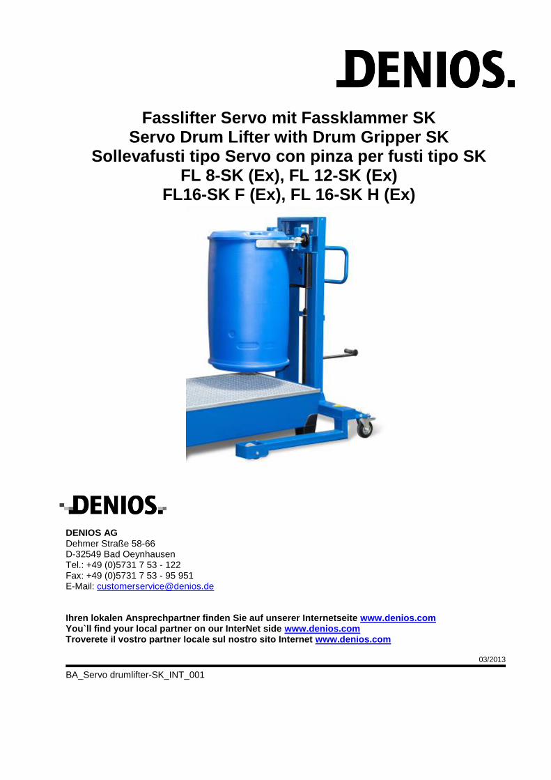
Fasslifter Servo mit Fassklammer SK Servo Drum Lifter with Drum Gripper SK
Sollevafusti tipo Servo con pinza per fusti tipo SK FL 8-SK (Ex), FL 12-SK (Ex)
FL16-SK F (Ex), FL 16-SK H (Ex)
DENIOS AG Dehmer Straße 58-66 D-32549 Bad Oeynhausen Tel.: +49 (0)5731 7 53 - 122 Fax: +49 (0)5731 7 53 - 95 951 E-Mail: [email protected]
Ihren lokalen Ansprechpartner finden Sie auf unserer Internetseite www.denios.com You`ll find your local partner on our InterNet side www.denios.com Troverete il vostro partner locale sul nostro sito Internet www.denios.com 03/2013
BA_Servo drumlifter-SK_INT_001
Fasslifter Servo mit Fassklammer SK Seite 2 von 17 Seiten Ausgabe 03/2014 214474, 214475, 214476, 214477 214478, 214479, 214480, 214481
Inhalt
Deutsch .................................................................................................................................. 3
1.Allgemeine Hinweise ........................................................................................................................................ 3
2. Sicherheitshinweise ........................................................................................................................................ 3
3. Einsatz und Verwendungszweck .................................................................................................................... 4
4. Technische Beschreibung ............................................................................................................................... 4
5. Aufbau und Inbetriebnahme ............................................................................................................................ 4
6. Technische Daten ........................................................................................................................................... 4
7. Betrieb ............................................................................................................................................................. 4
8. Wartung und Instandhaltung ........................................................................................................................... 5
9. EG-Konformitätserklärung ............................................................................................................................... 7
English.................................................................................................................................... 8
1. General Instructions ........................................................................................................................................ 8
2, Safety instructions ........................................................................................................................................... 8
3. Use and intended purpose .............................................................................................................................. 9
4. Technical description ...................................................................................................................................... 9
5. Assembly ......................................................................................................................................................... 9
6. Specifications .................................................................................................................................................. 9
7. Operation ......................................................................................................................................................... 9
8. Maintenance and servicing ........................................................................................................................... 10
9. Declaration of conformity .............................................................................................................................. 12
Italiano .................................................................................................................................. 12
1.Informazioni generali ...................................................................................................................................... 13
2. Indicazioni sulla sicurezza ............................................................................................................................. 13
3. Impiego e utilizzo .......................................................................................................................................... 14
4. Descrizione tecnica ....................................................................................................................................... 14
5. Montaggio e messa in servizio ...................................................................................................................... 14
6. Dati tecnici ..................................................................................................................................................... 14
7. Esercizio ........................................................................................................................................................ 14
8. Manutenzione ................................................................................................................................................ 15
9. Dichiarazione di conformità CE ..................................................................................................................... 17
Fasslifter Servo mit Fassklammer SK Seite 3 von 17 Seiten Ausgabe 03/2014 214474, 214475, 214476, 214477 214478, 214479, 214480, 214481
Deutsch
1.Allgemeine Hinweise
Ohne Genehmigung des Herstellers dürfen keine Veränderungen, An- oder Umbauten am Produkt vorgenommen werden. Für Veränderungen ohne Genehmigung des Herstellers wird keine Haftung übernommen und die Gewährleistung erlischt. Die nationalen Vorschriften und Sicherheitsbestimmungen sind zu beachten.
2. Sicherheitshinweise
Vor der Benutzung ist das Produkt auf seine einwandfreie Funktion zu überprüfen. Bei auftretenden Mängeln darf es nicht eingesetzt werden.
Es ist die BGV D8 (Winden, Hub- und Zuggeräte) und die BGV D27 (Flurförderfahrzeuge) zu beachten!
Nur für den vorgesehen Einsatz/Gebrauch einsetzen!
Die Last darf nicht im angehobenen Zustand belassen werden.
Zum Transport dürfen die Fässer nur leicht angehoben (ca. 50mm) sein.
Die angegebene Tragfähigkeit darf nicht überschritten werden!
Sicherheitshinweis für Ex-Ausführung
Umgang mit brennbaren Flüssigkeiten, Explosionsschutzmaßnahmen Beim Handling, der Lagerung und dem Umfüllen von Stoffen, die eine explosionsfähige Atmosphäre bilden können, müssen die Anforderungen der ATEX-Richtlinien 94/9/EG und 1999/92/EG in Verbindung mit dem Produktsicherheitsgesetz (ProdSG) und der Betriebssicherheitsverordnung (BetrSichV) beachtet werden. Je nach Ex-Zone sind geeignete Maßnahmen zu treffen. Die Verhinderung der Bildung der explosionsfähigen Atmosphäre durch Konzentrationsbeeinflussung (z.B. ausreichende Lüftung), Betriebsbedingungen und konstruktive Gestaltung (z.B. geeignete und zugelassene Behälter, geeigneter Lagerraum) muss im Vordergrund stehen. Die Vermeidung von Zündquellen durch elektrostatische Aufladungen durch einen elektrischen Potentialausgleich, Vermeidung mechanisch erzeugter Funken durch Verwendung von z.B. geeignetem Werkzeug, geeigneten Transport- und Beladehilfsmitteln und Vermeidung thermischer Zündquellen durch geeignete Verfahren, Verhinderung von Reibung, Blitzschutz, offenes Feuer, offenes Licht sowie Rauchen muss beachtet werden. Organisatorische Maßnahmen, wie Kennzeichnung der Bereiche, Anbringung von Warnzeichen, Zutrittsverbot für Unbefugte sind erforderlich. Die Betriebsmittel müssen in ordnungsgemäßem Zustand erhalten, ordnungsgemäß betrieben und ständig überwacht werden. Notwendige Reparaturen müssen sofort veranlasst werden. Reparaturen, die den Explosionsschutz der Betriebsmittel beeinflussen können, dürfen nur durch den Hersteller ausgeführt werden. Die Anforderungen an die Lagerung gemäß TRbF 20 sind zu beachten. Die elektrische Leitfähigkeit kann sich durch Ablagerungen behindernder Substanzen sowie durch chemische und mechanische Einflüsse so verändern, dass die in den Normen festgelegten zulässigen Werte überschritten werden. Insbesondere Staub, Schmutz und Farben, Säuren und Laugen, Überlastungen und Stoßbelastungen können dazu führen, dass die Ableitung elektrischer / elektrostatischer Energie in den Fußboden verhindert oder völlig unterbrochen wird. Halten Sie aus diesem Grund das Gerät, insbesondere Räder und Rollen sauber und nehmen keine zusätzlichen Lackierungen vor. Wegen der Fülle uns unbekannter Einflüsse beim Einsatz unserer Produkte kann sich unsere Gewährleistung hinsichtlich der elektrischen Leitfähigkeit ausschließlich auf die Einhaltung der in den Normen festgelegten zulässigen Werte der Räder im Neuzustand bei Lieferung beziehen. Die permanente Überwachung sicherheitstechnischer Vorschriften, wie z.B. die Einhaltung der Werte hinsichtlich der elektrischen Leitfähigkeit im Einsatz, liegt ausschließlich im Verantwortungsbereich des Anwenders. Beim Austausch von Bauteilen verwenden Sie ausschließlich DENIOS-Ersatzteile. Der Austausch gegen ungeeignete Bauteile führt zum Verlust der ATEX-Eignung.
Fasslifter Servo mit Fassklammer SK Seite 4 von 17 Seiten Ausgabe 03/2014 214474, 214475, 214476, 214477 214478, 214479, 214480, 214481
3. Einsatz und Verwendungszweck
Der Fasslifter Servo mit Fassklammer SK ermöglicht ein leichtes Heben und Verfahren von verschiedenen Stahl- und Kunststofffässern: - 205 – 230L-Stahlsickenfass gemäß DIN EN 15750-2 - 208 – 216,5L-Stahldeckelfass gemäß DIN EN 15750-1 - 220L-Kunststoff-Deckelfass - 220L-Kunststoff-L-Ringfass Die tatsächliche Eignung muß durch den Betreiber am Fass nachgewiesen werden. Der Untergrund muß glatt, eben und fest sein.
4. Technische Beschreibung
Der Fasslifter wird mit 4 verschiedenen Fahrwerken angeboten:
Servo Typ FL 8-K FL 12-K FL 16-K F FL 16-K H
Fahrwerk schmal breit breit breit
Gesamthöhe (mm) 1540 1540 2130 2130
Hubbereich (mm) 120 - 520 0 - 520 0 - 1170 0 - 1170
Ausführung mit Hydraulikpumpe mit Hydraulikpumpe mit Hydraulikpumpe mit Handkurbel
Füllmenge – Öl (L) 0,8 0,8 1,0 -
Der Fasslifter Servo ist wie folgt aufgebaut: - stabiles Fahrwerk mit Hubmast - verstellbare Fassklammer - Hydraulikpumpe mit Hubzylinder, bzw. Handkurbel mit Seilwinde- - je 2 Lenk- und Laufrollen (bei der Ex-Version in elektrisch ableitfähiger Ausführung)
5. Aufbau und Inbetriebnahme
Fasslifter mit Hydraulik-Pumpe:
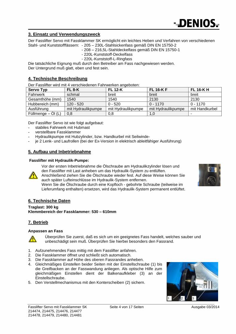
Vor der ersten Inbetriebnahme die Ölschraube am Hydraulikzylinder lösen und den Fasslifter mit Last anheben um das Hydraulik-System zu entlüften. Anschließend ziehen Sie die Ölschraube wieder fest. Auf diese Weise können Sie auch später Lufteinschlüsse im Hydraulik-System entfernen. Wenn Sie die Ölschraube durch eine Kopfloch - gebohrte Schraube (teilweise im Lieferumfang enthalten) ersetzen, wird das Hydraulik-System permanent entlüftet.
6. Technische Daten
Traglast: 300 kg Klemmbereich der Fassklammer: 530 – 610mm
7. Betrieb
Anpassen an Fass
Überprüfen Sie zuerst, daß es sich um ein geeignetes Fass handelt, welches sauber und unbeschädigt sein muß. Überprüfen Sie hierbei besonders den Fassrand.
1. Aufzunehmendes Fass mittig mit dem Fasslifter anfahren. 2. Die Fassklammer öffnet und schließt sich automatisch. 3. Die Fassklammer auf Höhe des oberen Fassrandes anheben. 4. Gleichmäßiges Einstellen beider Seiten mit der Einstellschraube (1) bis
die Greifbacken an der Fasswandung anliegen. Als optische Hilfe zum gleichmäßigen Einstellen dient der Balkenaufkleber (3) an der Einstellschraube.
5. Den Verstellmechanismus mit den Konterscheiben (2) sichern.
Fasslifter Servo mit Fassklammer SK Seite 5 von 17 Seiten Ausgabe 03/2014 214474, 214475, 214476, 214477 214478, 214479, 214480, 214481
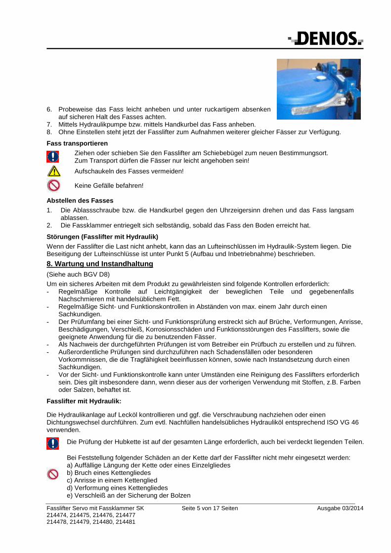
6. Probeweise das Fass leicht anheben und unter ruckartigem absenken
auf sicheren Halt des Fasses achten. 7. Mittels Hydraulikpumpe bzw. mittels Handkurbel das Fass anheben. 8. Ohne Einstellen steht jetzt der Fasslifter zum Aufnahmen weiterer gleicher Fässer zur Verfügung.
Fass transportieren
Ziehen oder schieben Sie den Fasslifter am Schiebebügel zum neuen Bestimmungsort. Zum Transport dürfen die Fässer nur leicht angehoben sein!
Aufschaukeln des Fasses vermeiden!
Keine Gefälle befahren!
Abstellen des Fasses
1. Die Ablassschraube bzw. die Handkurbel gegen den Uhrzeigersinn drehen und das Fass langsam ablassen.
2. Die Fassklammer entriegelt sich selbständig, sobald das Fass den Boden erreicht hat.
Störungen (Fasslifter mit Hydraulik)
Wenn der Fasslifter die Last nicht anhebt, kann das an Lufteinschlüssen im Hydraulik-System liegen. Die Beseitigung der Lufteinschlüsse ist unter Punkt 5 (Aufbau und Inbetriebnahme) beschrieben.
8. Wartung und Instandhaltung
(Siehe auch BGV D8)
Um ein sicheres Arbeiten mit dem Produkt zu gewährleisten sind folgende Kontrollen erforderlich: - Regelmäßige Kontrolle auf Leichtgängigkeit der beweglichen Teile und gegebenenfalls
Nachschmieren mit handelsüblichem Fett. - Regelmäßige Sicht- und Funktionskontrollen in Abständen von max. einem Jahr durch einen
Sachkundigen. - Der Prüfumfang bei einer Sicht- und Funktionsprüfung erstreckt sich auf Brüche, Verformungen, Anrisse,
Beschädigungen, Verschleiß, Korrosionsschäden und Funktionsstörungen des Fasslifters, sowie die geeignete Anwendung für die zu benutzenden Fässer.
- Als Nachweis der durchgeführten Prüfungen ist vom Betreiber ein Prüfbuch zu erstellen und zu führen. - Außerordentliche Prüfungen sind durchzuführen nach Schadensfällen oder besonderen
Vorkommnissen, die die Tragfähigkeit beeinflussen können, sowie nach Instandsetzung durch einen Sachkundigen.
- Vor der Sicht- und Funktionskontrolle kann unter Umständen eine Reinigung des Fasslifters erforderlich sein. Dies gilt insbesondere dann, wenn dieser aus der vorherigen Verwendung mit Stoffen, z.B. Farben oder Salzen, behaftet ist.
Fasslifter mit Hydraulik:
Die Hydraulikanlage auf Lecköl kontrollieren und ggf. die Verschraubung nachziehen oder einen Dichtungswechsel durchführen. Zum evtl. Nachfüllen handelsübliches Hydrauliköl entsprechend ISO VG 46 verwenden.
Die Prüfung der Hubkette ist auf der gesamten Länge erforderlich, auch bei verdeckt liegenden Teilen.
Bei Feststellung folgender Schäden an der Kette darf der Fasslifter nicht mehr eingesetzt werden: a) Auffällige Längung der Kette oder eines Einzelgliedes b) Bruch eines Kettengliedes c) Anrisse in einem Kettenglied d) Verformung eines Kettengliedes e) Verschleiß an der Sicherung der Bolzen
Fasslifter Servo mit Fassklammer SK Seite 6 von 17 Seiten Ausgabe 03/2014 214474, 214475, 214476, 214477 214478, 214479, 214480, 214481
Fasslifter mit Seilwinde:
Die Winde stets in einem guten Betriebszustand halten. Nicht gewartete Maschinenteile können zu Funktionsstörungen und zu Unfällen führen.
Die Prüfung des Seiles ist auf der gesamten Länge erforderlich, auch bei verdeckt liegenden Teilen.
Bei beschädigtem Drahtseil Fasslifter instand setzen und Seil austauschen.
Bei sichtbaren Verformungen oder Schäden ist der Fasslifter nicht mehr zu verwenden.
Fasslifter Servo mit Fassklammer SK Seite 7 von 17 Seiten Ausgabe 03/2014 214474, 214475, 214476, 214477 214478, 214479, 214480, 214481
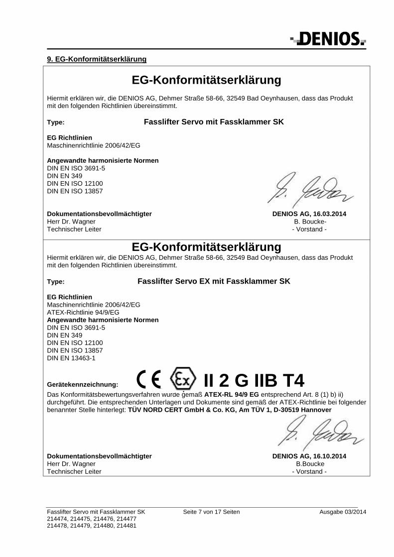
9. EG-Konformitätserklärung
EG-Konformitätserklärung Hiermit erklären wir, die DENIOS AG, Dehmer Straße 58-66, 32549 Bad Oeynhausen, dass das Produkt mit den folgenden Richtlinien übereinstimmt.
Type: Fasslifter Servo mit Fassklammer SK
EG Richtlinien Maschinenrichtlinie 2006/42/EG Angewandte harmonisierte Normen DIN EN ISO 3691-5 DIN EN 349 DIN EN ISO 12100 DIN EN ISO 13857
Dokumentationsbevollmächtigter DENIOS AG, 16.03.2014 Herr Dr. Wagner B. Boucke- Technischer Leiter - Vorstand -
EG-Konformitätserklärung Hiermit erklären wir, die DENIOS AG, Dehmer Straße 58-66, 32549 Bad Oeynhausen, dass das Produkt mit den folgenden Richtlinien übereinstimmt.
Type: Fasslifter Servo EX mit Fassklammer SK EG Richtlinien Maschinenrichtlinie 2006/42/EG ATEX-Richtlinie 94/9/EG Angewandte harmonisierte Normen DIN EN ISO 3691-5 DIN EN 349 DIN EN ISO 12100 DIN EN ISO 13857 DIN EN 13463-1
Gerätekennzeichnung: II 2 G IIB T4
Das Konformitätsbewertungsverfahren wurde gemäß ATEX-RL 94/9 EG entsprechend Art. 8 (1) b) ii) durchgeführt. Die entsprechenden Unterlagen und Dokumente sind gemäß der ATEX-Richtlinie bei folgender benannter Stelle hinterlegt: TÜV NORD CERT GmbH & Co. KG, Am TÜV 1, D-30519 Hannover
Dokumentationsbevollmächtigter DENIOS AG, 16.10.2014 Herr Dr. Wagner B.Boucke Technischer Leiter - Vorstand -
Fasslifter Servo mit Fassklammer SK Seite 8 von 17 Seiten Ausgabe 03/2014 214474, 214475, 214476, 214477 214478, 214479, 214480, 214481
English
1. General Instructions
No modifications or alterations can be made to the product without authorisation from the manufacturer, in the event of this, the guarantee will be invalidated. National standards and safety regulations must be observed.
2, Safety instructions
Before the product is used, it is to be checked for correct functioning. Should any defects appear, it must not be used!
Only use for the intended purpose!
The load must not be left in raised position.
The drums must only be raised slightly (50mm) for when being transported.
The bearing capacity given must not be exceeded!
Safety instructions for EX-model Handling inflammable liquids, explosion-proof systems When handling, storing, and refilling of substances that can form an explosive atmosphere, it is mandatory to comply with the requirements in the ATEX directives 94/9/EC and 1999/92/EC and in connection with it, to observe the Product Safety Act (ProdSG) and the regulation for industrial health and safety (BetrSichV).The electrical conductivity of the wheels and wheel linings can be changed by the depositing of hindering substances and also by chemical and mechanical influences in such a way that the allowable values laid down in the standards are exceeded. In particular, dust, dirt and paint, acids and alkalis, overloads and impact loads can lead to the discharge/conduction of electric/electrostatic energy to the floor being reduced or completely interrupted. Because of the abundance of influences unknown to us in the use of our products our guarantee with respect to the electrical conductivity relates exclusively to the compliance with the permitted values of the wheels in new condition on delivery laid down in the standards. The constant observation of technical safety regulations such as e.g. compliance with the values with respect to electrical conductivity in use is exclusively in the area of responsibility of the user. The exchange of the wheels for a non-conductive version leads to a loss of the ATEX eligibility. As a lashing strap only an antistatic model must be used. The exchange of the strap for a non-conductive version leads to a loss of the ATEX eligibility. Chemical and mechanical influences as well as the accumulation of obstructive substances can alter electrical conductivity to such an extent that the permitted levels laid out in standards are exceeded. Dust, dirt, paint, acids, leaches, overloading and impact loads, in particular, may impede or completely prevent electrical or electrostatic energy from being relayed to the ground. For this reason, you must keep the device completely clean, especially its wheels and castors, and you must not apply an extra layer of paint. Because of the abundance of influences unknown to us in the use of our products our guarantee with respect to the electrical conductivity relates exclusively to the compliance with the permitted values of the wheels in new condition on delivery laid down in the standards. The constant observation of technical safety regulations such as e.g. compliance with the values with respect to electrical conductivity in use is exclusively in the area of responsibility of the user. Only use DENIOS replacement parts when replacing components. Replacing with unsuitable parts will mean the device is no longer ATEX-compatible.
Fasslifter Servo mit Fassklammer SK Seite 9 von 17 Seiten Ausgabe 03/2014 214474, 214475, 214476, 214477 214478, 214479, 214480, 214481
3. Use and intended purpose
The Servo drum lifter with drum grippers type SK allows the easy lifting and moving of different steel- and plastic drums: - 205 – 230L steel drums acc. EN 15750-2 - 208 – 216,5L steel drums w. removable head acc. EN 15750-1 - 220L plastic drum w. removable head - 220L plastic dum The actual suitability must be demonstrated by the operator at the drum. The floor must be plane, even, and stable.
4. Technical description
The drum lifter can be supplied with 4 different wheel bases:
Servo Model FL 8-K FL 12-K FL 16-K FL 16-K H
Wheel base narrow wide wide wide
Total height (mm) 1540 1540 2130 2130
Lifting range (mm) 120 - 520 0 - 520 0 - 1170 0 - 1170
Version with hydraulic pump with hydraulic pump with hydraulic pump with hand crank
The Servo Drum Lifter includes the following features: - stable wheel base with lifting mast - adjustable drum gripper - hydraulic pump with lifting cylinder or crank with winch - - two castors and two wheels (explosion-proof version with electrically conductive design)
5. Assembly
Drum lifter with hydraulic pump:
Before using for the first time, loosen the oil screw on the hydraulic cylinder and raise the drum lifter with a load to remove the air from the hydraulic system. Then re-fasten the oil screw tightly. You can also remove any air bubbles from the hydraulic system this way if required at a later date. If you replace the oil screw with a screw with a holed head (supplied with some models), air is permanently removed from the hydraulic system
6. Specifications
Safe working load: 300 kg Clamping range: 530 – 610mm
7. Operation
Adapt to drum
Firstly check, that the drum is suitable and must be clean and undamaged. Especially check the rim of drum.
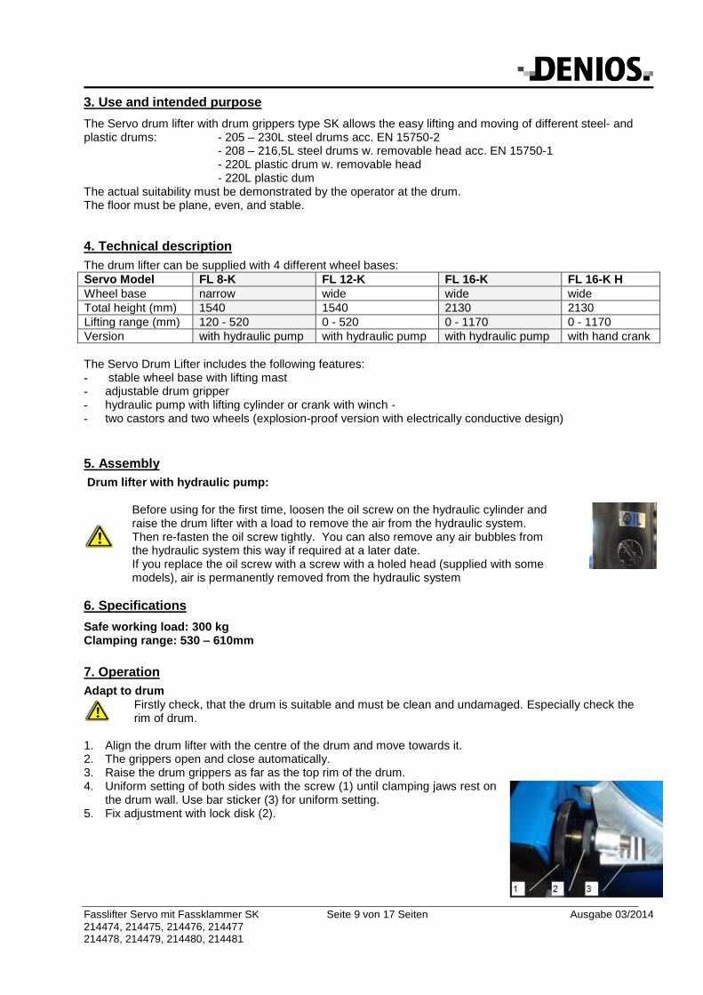
1. Align the drum lifter with the centre of the drum and move towards it. 2. The grippers open and close automatically. 3. Raise the drum grippers as far as the top rim of the drum. 4. Uniform setting of both sides with the screw (1) until clamping jaws rest on
the drum wall. Use bar sticker (3) for uniform setting. 5. Fix adjustment with lock disk (2).
Fasslifter Servo mit Fassklammer SK Seite 10 von 17 Seiten Ausgabe 03/2014 214474, 214475, 214476, 214477 214478, 214479, 214480, 214481
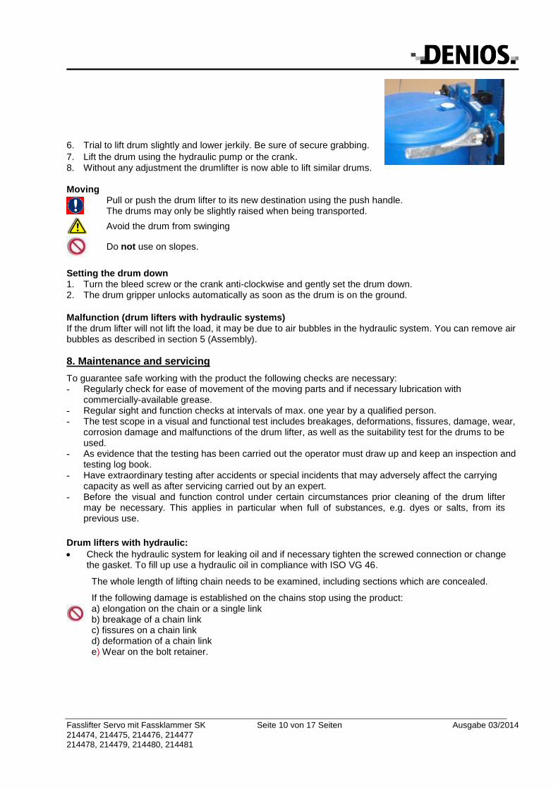
6. Trial to lift drum slightly and lower jerkily. Be sure of secure grabbing.
7. Lift the drum using the hydraulic pump or the crank. 8. Without any adjustment the drumlifter is now able to lift similar drums. Moving
Pull or push the drum lifter to its new destination using the push handle. The drums may only be slightly raised when being transported.
Avoid the drum from swinging
Do not use on slopes.
Setting the drum down 1. Turn the bleed screw or the crank anti-clockwise and gently set the drum down. 2. The drum gripper unlocks automatically as soon as the drum is on the ground.
Malfunction (drum lifters with hydraulic systems) If the drum lifter will not lift the load, it may be due to air bubbles in the hydraulic system. You can remove air bubbles as described in section 5 (Assembly).
8. Maintenance and servicing
To guarantee safe working with the product the following checks are necessary: - Regularly check for ease of movement of the moving parts and if necessary lubrication with
commercially-available grease. - Regular sight and function checks at intervals of max. one year by a qualified person. - The test scope in a visual and functional test includes breakages, deformations, fissures, damage, wear,
corrosion damage and malfunctions of the drum lifter, as well as the suitability test for the drums to be used.
- As evidence that the testing has been carried out the operator must draw up and keep an inspection and testing log book.
- Have extraordinary testing after accidents or special incidents that may adversely affect the carrying capacity as well as after servicing carried out by an expert.
- Before the visual and function control under certain circumstances prior cleaning of the drum lifter may be necessary. This applies in particular when full of substances, e.g. dyes or salts, from its previous use.
Drum lifters with hydraulic:
Check the hydraulic system for leaking oil and if necessary tighten the screwed connection or change the gasket. To fill up use a hydraulic oil in compliance with ISO VG 46.
The whole length of lifting chain needs to be examined, including sections which are concealed.
If the following damage is established on the chains stop using the product: a) elongation on the chain or a single link b) breakage of a chain link c) fissures on a chain link d) deformation of a chain link e) Wear on the bolt retainer.
Fasslifter Servo mit Fassklammer SK Seite 11 von 17 Seiten Ausgabe 03/2014 214474, 214475, 214476, 214477 214478, 214479, 214480, 214481
Drum lifters with winch:
Always keep the winch in good operating condition. Unmaintained machine parts may lead to malfunctions and accidents!
The whole length of therope needs to be examined, including sections which are concealed.
If the wire rope is damaged, repair the drum lifter and replace the rope
In case of visible deformation or obvious damage the drum lifter must not be used further
Fasslifter Servo mit Fassklammer SK Seite 12 von 17 Seiten Ausgabe 03/2014 214474, 214475, 214476, 214477 214478, 214479, 214480, 214481
9. Declaration of conformity
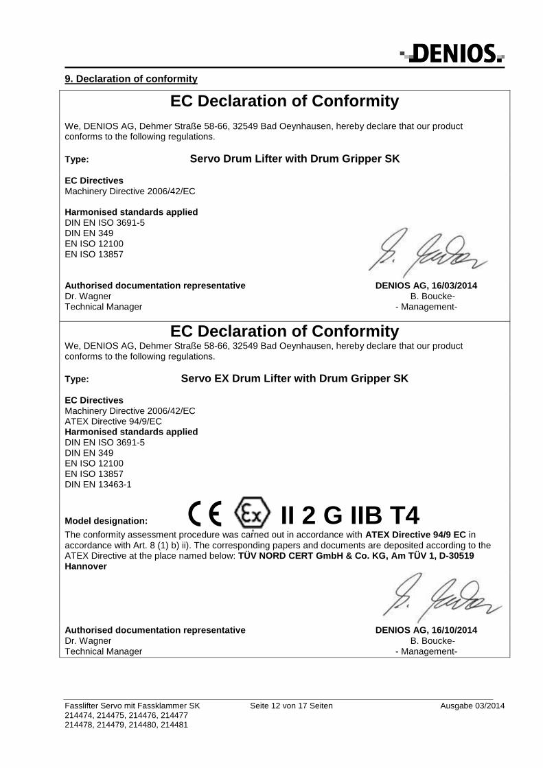
EC Declaration of Conformity We, DENIOS AG, Dehmer Straße 58-66, 32549 Bad Oeynhausen, hereby declare that our product conforms to the following regulations.
Type: Servo Drum Lifter with Drum Gripper SK
EC Directives Machinery Directive 2006/42/EC Harmonised standards applied DIN EN ISO 3691-5 DIN EN 349 EN ISO 12100 EN ISO 13857
Authorised documentation representative DENIOS AG, 16/03/2014 Dr. Wagner B. Boucke- Technical Manager - Management-
EC Declaration of Conformity We, DENIOS AG, Dehmer Straße 58-66, 32549 Bad Oeynhausen, hereby declare that our product conforms to the following regulations.
Type: Servo EX Drum Lifter with Drum Gripper SK EC Directives Machinery Directive 2006/42/EC ATEX Directive 94/9/EC Harmonised standards applied DIN EN ISO 3691-5 DIN EN 349 EN ISO 12100 EN ISO 13857 DIN EN 13463-1
Model designation: II 2 G IIB T4
The conformity assessment procedure was carried out in accordance with ATEX Directive 94/9 EC in accordance with Art. 8 (1) b) ii). The corresponding papers and documents are deposited according to the ATEX Directive at the place named below: TÜV NORD CERT GmbH & Co. KG, Am TÜV 1, D-30519 Hannover
Authorised documentation representative DENIOS AG, 16/10/2014 Dr. Wagner B. Boucke- Technical Manager - Management-
Fasslifter Servo mit Fassklammer SK Seite 13 von 17 Seiten Ausgabe 03/2014 214474, 214475, 214476, 214477 214478, 214479, 214480, 214481
Italiano
1.Informazioni generali
Senza autorizzazione del produttore non possono essere apportate modifiche, aggiunte o trasformazioni al prodotto. In caso di modifiche senza l'autorizzazione del produttore questi non si assume alcuna responsabilità e decade la garanzia. Devono essere rispettate le normative e le prescrizioni nazionali di sicurezza.
2. Indicazioni sulla sicurezza
Prima di utilizzare il prodotto è necessario controllarne il corretto funzionamento. Dovessero presentarsi eventuali difetti, non deve essere utilizzato.
Devono essere rispettate le normative tedesche BGV D8 (argani, apparecchi di sollevamento e di trazione) e BGV D27 (veicoli per trasporto interno)!
Utilizzare solo per lo scopo previsto!
Il carico non deve essere lasciato in posizione sollevata.
Per il trasporto i fusti possono essere sollevati solo leggermente (ca. 50 mm).
Non superare la capacità di carico specificata!
Istruzioni di sicurezza per la versione antideflagrante
Gestione di liquidi infiammabili, sistemi di protezione contro le esplosioni Durante la movimentazione, lo stoccaggio e il travaso di sostanze che possono formare un'atmosfera esplosiva, devono essere rispettati i requisiti delle direttive ATEX 94/9/CE e 1999/92/CE, unitamente a quanto disposto dalla legge tedesca sulla sicurezza delle apparecchiature e dei prodotti (ProdSG) e il regolamento tedesco sulla sicurezza degli impianti (BetrSichV). A seconda della zona Ex devono essere adottate misure adeguate. Devono essere considerate prioritarie la prevenzione della formazione dell'atmosfera esplosiva mediante l’influenza sulla concentrazione (per esempio, ventilazione adeguata), le condizioni operative e la progettazione strutturale (ad es. contenitori adeguati e approvati, locale di stoccaggio appropriato). È necessario evitare fonti di accensione da cariche elettrostatiche con una messa a equipotenziale elettrico, evitare scintille di origine meccanica utilizzando, ad esempio, strumenti adeguati e mezzi di trasporto e sistemi di carico idonei, evitare fonti termiche di accensione attraverso procedure appropriate. Si deve inoltre prestare attenzione onde evitare attriti, fiamme libere e fumo e provvedere alla protezione contro i fulmini. Sono necessarie misure organizzative quali l'identificazione delle aree, l’applicazione di segnali di pericolo, i cartelli di divieto di accesso alle persone non autorizzate. I dispositivi devono essere conservati in buone condizioni, fatti funzionare correttamente e monitorati costantemente. Le riparazioni necessarie devono essere effettuate immediatamente. Le riparazioni che possono influire sulla protezione contro le esplosioni delle attrezzature possono essere eseguite solo dal costruttore. Devono essere osservati i requisiti per lo stoccaggio secondo quanto previsto dalla norma tecnica tedesca per i liquidi infiammabili TRbF 20. La conducibilità elettrica può essere modificata da depositi di sostanze ostruttive, nonché da agenti chimici e meccanici, fino a causare il superamento dei valori ammissibili stabiliti dalle norme. In particolare, polvere, sporcizia e vernici, acidi e soluzioni alcaline, sovraccarichi e urti possono impedire o interrompere completamente la dissipazione di energia elettrica/elettrostatica al suolo. Per questo motivo è necessario tenere pulito il dispositivo, in particolare ruote e rulli, e non si devono applicare ulteriori strati di vernice. A causa della molteplicità di fattori a noi sconosciuti che possono influire durante l'utilizzo dei nostri prodotti, la nostra garanzia, in termini di conducibilità elettrica, si riferisce soltanto al rispetto dei valori consentiti, previsti dalle norme, delle ruote nuove, al momento della consegna. Il monitoraggio costante dei requisiti tecnici relativi alla sicurezza, come ad esempio il rispetto dei valori in termini di conducibilità elettrica nell’uso, è di esclusiva responsabilità dell'utilizzatore. In caso di sostituzione di componenti, utilizzare solo pezzi di ricambio DENIOS. La sostituzione con componenti non adatti porta alla perdita dell'idoneità ATEX.
Fasslifter Servo mit Fassklammer SK Seite 14 von 17 Seiten Ausgabe 03/2014 214474, 214475, 214476, 214477 214478, 214479, 214480, 214481
3. Impiego e utilizzo
Il sollevafusti Servo con pinza per fusti SK consente di sollevare e trasportare con facilità diversi fusti in acciaio e plastica: - Fusto in acciaio con nervature, da 205 a 230 litri, esecuzione secondo DIN EN 15750-2 - Fusto in acciaio al carbonio con coperchio, da 208 a 216 litri, esecuzione secondo DIN EN 15750-1 - Fusto in plastica da 220 litri con coperchio - Fusto in plastica L-Ring da 220 litri L'effettiva idoneità deve essere verificata dall'operatore sul fusto. Il fondo deve essere liscio, piano e stabile.
4. Descrizione tecnica
Il sollevafusti è disponibile con 4 carrelli diversi:
Servo tipo FL 8-K FL 12-K FL 16-K F FL 16-K H
Carrello stretto largo largo largo
Altezza totale (mm):
1540 1540 2130 2130
Corsa di sollevamento(mm)
120 - 520 0 - 520 0 - 1170 0 - 1170
Versione con pompa idraulica con pompa idraulica con pompa idraulica con manovella
Capacità - Olio (litri)
0,8 0,8 1,0 -
Il sollevafusti Servo è costruito come segue: - robusto carrello con montante di sollevamento - pinza regolabile per fusti - Pompa idraulica con cilindro di sollevamento, o manovella con verricello - 2 ruote girevoli e due fisse (nella versione antideflagrante in esecuzione elettricamente conduttiva)
5. Montaggio e messa in servizio
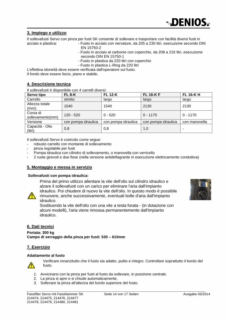
Sollevafusti con pompa idraulica:
Prima del primo utilizzo allentare la vite dell'olio sul cilindro idraulico e alzare il sollevafusti con un carico per eliminare l'aria dall'impianto idraulico. Poi chiudere di nuovo la vite dell'olio. In questo modo è possibile rimuovere, anche successivamente, eventuali bolle d'aria dall'impianto idraulico. Sostituendo la vite dell'olio con una vite a testa forata - (in dotazione con alcuni modelli), l'aria viene rimossa permanentemente dall'impianto idraulico.
6. Dati tecnici
Portata: 300 kg Campo di serraggio della pinza per fusti: 530 – 610mm
7. Esercizio
Adattamento al fusto
Verificare innanzitutto che il fusto sia adatto, pulito e integro. Controllare soprattutto il bordo del fusto.
1. Avvicinarsi con la pinza per fusti al fusto da sollevare, in posizione centrale. 2. La pinza si apre e si chiude automaticamente. 3. Sollevare la pinza all'altezza del bordo superiore del fusto.
Fasslifter Servo mit Fassklammer SK Seite 15 von 17 Seiten Ausgabe 03/2014 214474, 214475, 214476, 214477 214478, 214479, 214480, 214481
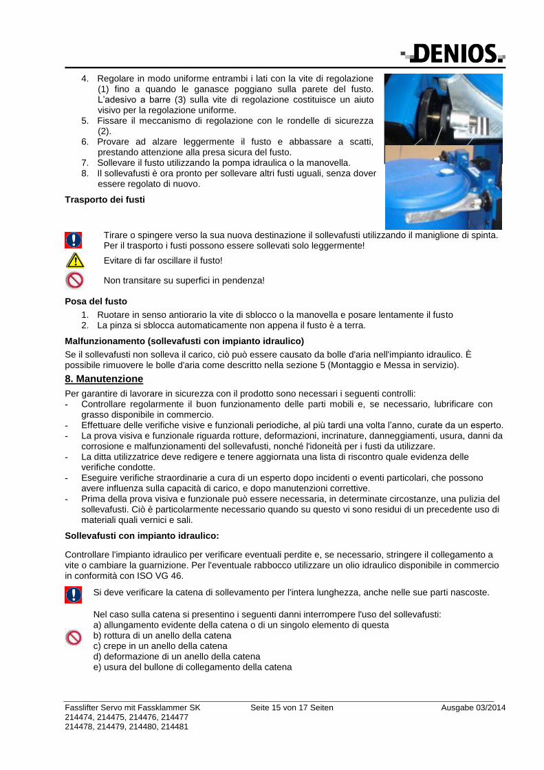
4. Regolare in modo uniforme entrambi i lati con la vite di regolazione (1) fino a quando le ganasce poggiano sulla parete del fusto. L’adesivo a barre (3) sulla vite di regolazione costituisce un aiuto visivo per la regolazione uniforme.
5. Fissare il meccanismo di regolazione con le rondelle di sicurezza (2).
6. Provare ad alzare leggermente il fusto e abbassare a scatti, prestando attenzione alla presa sicura del fusto.
7. Sollevare il fusto utilizzando la pompa idraulica o la manovella. 8. Il sollevafusti è ora pronto per sollevare altri fusti uguali, senza dover
essere regolato di nuovo.
Trasporto dei fusti
Tirare o spingere verso la sua nuova destinazione il sollevafusti utilizzando il maniglione di spinta. Per il trasporto i fusti possono essere sollevati solo leggermente!
Evitare di far oscillare il fusto!
Non transitare su superfici in pendenza!
Posa del fusto
1. Ruotare in senso antiorario la vite di sblocco o la manovella e posare lentamente il fusto 2. La pinza si sblocca automaticamente non appena il fusto è a terra.
Malfunzionamento (sollevafusti con impianto idraulico)
Se il sollevafusti non solleva il carico, ciò può essere causato da bolle d'aria nell'impianto idraulico. È possibile rimuovere le bolle d'aria come descritto nella sezione 5 (Montaggio e Messa in servizio).
8. Manutenzione
Per garantire di lavorare in sicurezza con il prodotto sono necessari i seguenti controlli: - Controllare regolarmente il buon funzionamento delle parti mobili e, se necessario, lubrificare con
grasso disponibile in commercio. - Effettuare delle verifiche visive e funzionali periodiche, al più tardi una volta l’anno, curate da un esperto. - La prova visiva e funzionale riguarda rotture, deformazioni, incrinature, danneggiamenti, usura, danni da
corrosione e malfunzionamenti del sollevafusti, nonché l'idoneità per i fusti da utilizzare. - La ditta utilizzatrice deve redigere e tenere aggiornata una lista di riscontro quale evidenza delle
verifiche condotte. - Eseguire verifiche straordinarie a cura di un esperto dopo incidenti o eventi particolari, che possono
avere influenza sulla capacità di carico, e dopo manutenzioni correttive. - Prima della prova visiva e funzionale può essere necessaria, in determinate circostanze, una pulizia del
sollevafusti. Ciò è particolarmente necessario quando su questo vi sono residui di un precedente uso di materiali quali vernici e sali.
Sollevafusti con impianto idraulico:
Controllare l'impianto idraulico per verificare eventuali perdite e, se necessario, stringere il collegamento a vite o cambiare la guarnizione. Per l'eventuale rabbocco utilizzare un olio idraulico disponibile in commercio in conformità con ISO VG 46.
Si deve verificare la catena di sollevamento per l'intera lunghezza, anche nelle sue parti nascoste.
Nel caso sulla catena si presentino i seguenti danni interrompere l'uso del sollevafusti: a) allungamento evidente della catena o di un singolo elemento di questa b) rottura di un anello della catena c) crepe in un anello della catena d) deformazione di un anello della catena e) usura del bullone di collegamento della catena
Fasslifter Servo mit Fassklammer SK Seite 16 von 17 Seiten Ausgabe 03/2014 214474, 214475, 214476, 214477 214478, 214479, 214480, 214481
Sollevafusti con verricello:
Tenere sempre il verricello in buone condizioni di funzionamento. Parti della macchina non sottoposte a regolare manutenzione possono causare malfunzionamenti e incidenti.
Il controllo della fune è richiesto per l'intera lunghezza, anche per le parti nascoste.
Se la fune è danneggiata, riparare il sollevafusti e sostituire la fune.
In caso di deformazioni visibili o danni evidenti il sollevafusti non deve essere utilizzato ulteriormente.
Fasslifter Servo mit Fassklammer SK Seite 17 von 17 Seiten Ausgabe 03/2014 214474, 214475, 214476, 214477 214478, 214479, 214480, 214481
9. Dichiarazione di conformità CE
Dichiarazione di conformità CE Con la presente noi, DENIOS AG, Dehmer Straße 58-66, 32549 Bad Oeynhausen, dichiariamo che il prodotto è conforme alle seguenti direttive.
Tipo: Sollevafusti Servo FL con pinza per fusti SK
Direttive CE Direttiva Macchine 2006/42/CE Norme armonizzate applicate DIN EN ISO 3691-5 DIN EN 349 DIN EN ISO 12100 DIN EN ISO 13857
Responsabile della documentazione DENIOS AG, 16.03.2014 Herr Dr.Wagner- B. Boucke Direttore tecnico - Consiglio di amministrazione -
Dichiarazione di conformità CE Con la presente noi, DENIOS AG, Dehmer Straße 58-66, 32549 Bad Oeynhausen, dichiariamo che il prodotto è conforme alle seguenti direttive.
Tipo: Sollevafusti Servo EX con pinza per fusti SK Direttive CE Direttiva Macchine 2006/42/CE Direttiva ATEX 94/9/CE Norme armonizzate applicate DIN EN ISO 3691-5 DIN EN 349 DIN EN ISO 12100 DIN EN ISO 13857 DIN EN 13463-1
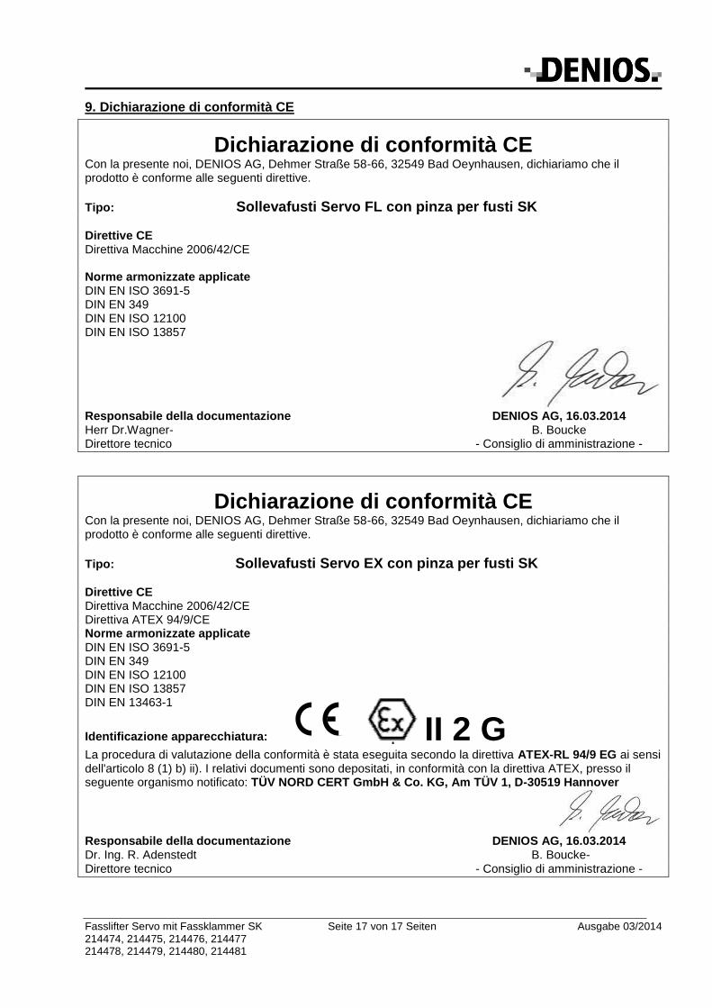
Identificazione apparecchiatura: II 2 G
La procedura di valutazione della conformità è stata eseguita secondo la direttiva ATEX-RL 94/9 EG ai sensi dell'articolo 8 (1) b) ii). I relativi documenti sono depositati, in conformità con la direttiva ATEX, presso il seguente organismo notificato: TÜV NORD CERT GmbH & Co. KG, Am TÜV 1, D-30519 Hannover
Responsabile della documentazione DENIOS AG, 16.03.2014 Dr. Ing. R. Adenstedt B. Boucke- Direttore tecnico - Consiglio di amministrazione -