Embed Size (px)
Citation preview

International Journal of Machine Tools & Manufacture 41 (2001) 1535–1550
Servo parameter tuning for a 5-axis machine center basedupon GA rules
Lun-Yu Kuo a, Jia-Yush Yen b,*
a Mechanical Engineering Research Laboratory, Industrial Technology Research Center, Taichung, Taiwan, ROCb Department of Mechanical Engineering, National Taiwan University, No. 1 Sec. 4 Roosevelt Road, Taipei, Taiwan
10617, ROC
Received 14 August 2000; received in revised form 6 December 2000; accepted 21 February 2001
Abstract
This paper addresses the use of the genetic algorithm (GA) to tune the servo controller in a multi-axisCNC machine center. Because the number of parameters in a CNC controller is usually very large andtheir effects are highly coupled, tuning these parameters is a task requiring great skill. In this paper, thegenetic algorithm is applied to tune the servo parameters in a commercial CNC machine controller. Thecontroller is a PC-based open architecture system, thus allowing the GA to be implemented on a personalcomputer. In this study, a dynamic mutation amplitude process is also introduced to improve the qualityof evolution. Experimental results obtained on a Siemens 840D CNC controller indicate that the proposedmethod is able to automatically identify the effect of each parameter and to tune the controller so as toachieve expert level performance. 2001 Elsevier Science Ltd. All rights reserved.
Keywords: Servosystems; Motion control; Machine tool control
1. Introduction
The motion controller in a multi-axis CNC machine center is usually a very complicated system.Unlike the conventional servo controller that is composed of only a single (may be verysophisticated) control law, CNC controllers usually consist of several control blocks that worktogether to satisfy the various machining requirements.
The servo design philosophy in a CNC controller differs from the traditional control approachbecause there is almost no prior knowledge of the working plant. The servo engineers must
* Corresponding author. Tel.: +886-2-2366-0734; fax: +886-2-2366-0735.E-mail address: [email protected] (J.-Y. Yen).
0890-6955/01/$ - see front matter 2001 Elsevier Science Ltd. All rights reserved.PII: S0 890- 695 5(01 )000 31- 1

1536 L.-Y. Kuo, J.-Y. Yen / International Journal of Machine Tools & Manufacture 41 (2001) 1535–1550
understand that the loading and the cutting conditions in a machine tool can vary from case tocase; therefore a controller tuned with constant plant assumption would not maintain satisfactoryperformance. To achieve consistent performance, the core motion controller has to sacrifice agreat deal of performance to maintain the required system robustness. The various control functionblocks then help compensate for the varying path changes, friction, etc. These functions includedynamic response matching, which makes the impedance of all axes identical, speed feedforwardcontrol, which controls the time constant of the speed control loop, current feedforward control,which compensates for the motor and load inertia, and the friction compensation, which is usefulwhen the machine encounters errors caused by friction force. Usually, various parameters areavailable in a CNC machine controller to adjust the various functions. Unfortunately, there is noobvious correlation between the parameters and the servo performance, and their effects are oftenheavily coupled. Adjusting these parameters requires much experience and patience. In most cases,large controller manufacturers like FANUC or Siemens have to send their engineers out to helpcustomers tune their controllers.
The goal of this research is to make the servo engineer’s task easier by developing an automatedtuning method for these parameters. Because a CNC controller is a very complicated system,most previous works have focused on a subset (or a specific function) of a controller [1–7]. Thefew papers that have addressed the entire system have only described the system at the functionallevel [8]. Due to developments in machine intelligence, many recent results have started to incor-porate machine intelligent into servo systems [9–15]. Basically, these researches have offered newways to tune controllers with fixed structures or to generate control rules. There are also reportson many successful applications [16–19]. However, they are also restricted to single functioncontrollers. The work by Tarng, Chuang, and Hsu [19] addressed the CNC controller, but theyalso focused on the federate control function.
This work will address all the most useful control functions in a CNC controller in order tominimize the need for experts. Note that the number of parameters in this kind of controller isvery large, and that the effects of these parameters are coupled. There is really no apparentrelationship between the parameters and the control outcome. Thus, it is very difficult to establishsensible rule base for tuning these parameters. It is perhaps a very suitable case for applyinggenetic algorithms (GA). In this research, a PC-based Open CNC controller based on the Siemensonline tuning procedure. A GA algorithm is in charge of tuning these parameters. Through theevolution of genes (where each gene represents a parameter), the controller gradually adapts itselfso as to achieve better performance. To improve on the quality of convergence, a dynamicmutation amplitude method is also introduced. Experimental results indicate that the GA algorithmis able to achieve expert performance. The control results are superior to results obtained throughtuning by a trained expert.
In the following sections, Section 2 presents a brief description of the functions and the associa-ted parameters of a multi-axis CNC controller. This section will also include some expert opinionson how to tune these parameters. Section 3 presents the experimental CNC machine center as wellas the actual implementation in detail. Section 4 presents various control experiment situations,experimental results and some discussion of the data will be presented. Section 5 presents con-clusions.
1537L.-Y. Kuo, J.-Y. Yen / International Journal of Machine Tools & Manufacture 41 (2001) 1535–1550
2. The multi-axis CNC machine tool controller
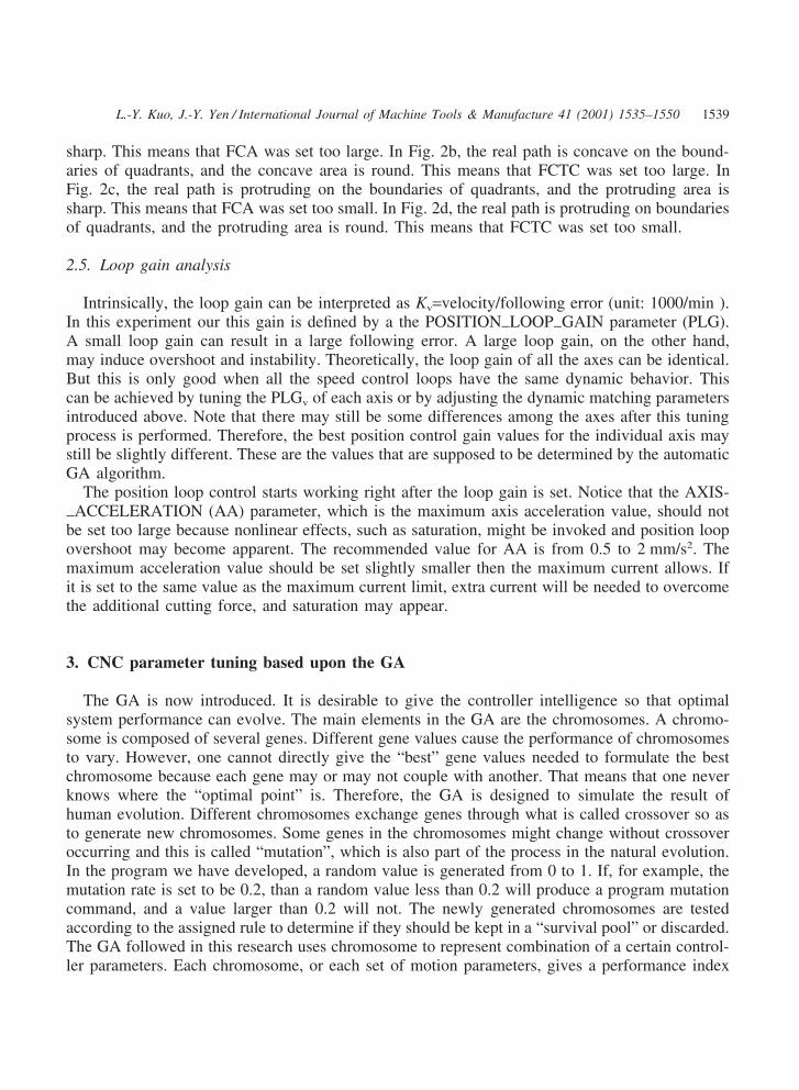
The system setup was designed to facilitate research on the motion control performance of a5-axis machining tool. The 5-axis machining tool was developed in the “High Speed Machiningof Complex Surfaces” project sponsored by the Ministry of Economic Affairs of the ROC govern-ment. The setup utilizes a home grown PC-based controller. The controller, is based on use ofSiemens 840D control kernel for the machine tool controller. The interpolation time for thiscontroller is 2 ms. Thanks to the CNC controller’s open architecture, it is possible to bypass theinterface adaptation problem and to integrate in-house control modules into the system. Fig. 1shows the block diagram of the position loop control.
In the following subsections the effects of some of the most import motion control functionswill be explained, and a set of associated parameters will be defined.
2.1. Dynamic response matching
The goal of this parameter is to align the impedance of all the servo axes. Although it ispossible to tune separate axis loop gains so as to make the errors from each axis similar, thereare times when the performance of some axes might deteriorate. Long rise time or large overshootmay occur. In addition, a high servo gain will lead to better disturbance suppression; one shouldnot sacrifice good servo gain in order to match axes having inferior performance. For thesereasons, the system uses dynamic response matching to synchronize axis performance and toreduce the resulting errors. In the course of developing the algorithm and programming thesoftware, we define a dynamic response matching parameter called DYNAMICFMATCHINGFTI-MEFCONSTANT (DMTC), and this term will be used in the following description. To set thisparameter, the axis with the lowest gain is selected as the base axis. If the time constant of someaxis is 3 ms faster than the base axis, then the parameter of this axis is set to 0.003 s.
2.2. Speed feedforward control
The speed feedforward control gain, as the name indicates, adjusts the feedforward controllergain. We define a speed feedforward control gain parameter called SPEEDFFEEDFOR-WARDFGAIN (SFG). A parameter called SPEEDFCONTROLFTIMEFCONSTANT (SCTC) isalso introduced to represent the equivalent time constant of the speed control loop. The equivalenttime constant of the speed control loop is generally set to 1/10th time constant of the positioncontrol loop. The time constant normally ranges from 1 to 5 ms. If the time constant of the speedcontrol loop is set correctly, a feedforward control factor with a value of 1 can produce a speedloop error that is close to zero. Of course, there is always some error in evaluation, and further
Fig. 1. CNC controller block diagram.

1538 L.-Y. Kuo, J.-Y. Yen / International Journal of Machine Tools & Manufacture 41 (2001) 1535–1550
fine-tuning is needed. Generally, larger values of these parameters lead to stronger feedforwardeffects.
2.3. Current feedforward control
The parameter that represents the axis inertia is called AXISFINERTIA (AI), and it influencesthe effect of the current loop feedforward gain. The current loop mainly works to eliminate theinertia effect. The total axis inertia includes the inertia of the motor and that of the load. Anotherparameter that controls the time constant of the current loop is called EQUIVELENTFCUR-RENTFCONTROLFTIMEFCONSTANT (EQCCTC). The value of this parameter can be obtainedfrom the step response of the current loop. Setting a large value for AI larger and a small valuefor EQCCTC will enhance the effect of the current loop feedforward control, however, one usuallytries to avoid setting very large values to these parameters.
Notice that the original following error will be cancelled out by the action of the feedforwardcontrol if the feedforward control is set precisely. Thus, theoretically, the servo gain factor forthe position control gain (Kp) should not affect the following error during trajectory tracking.
2.4. Friction compensation
When the machine moves in a circle, position errors occur at the boundary of each quadrant.These errors are caused by friction and are commonly called “spikes”. A set of associated para-meters is defined so as to compensate for this effect. The paremeters are defined as follows:FRICTIONFCOMPENSATIONFENABLE (FCE), enables friction compensation; FRICTION-FCOMPENSATIONFAMPLITUDE (FCA), the friction compensation value (amplitude); andFRICTIONFCOMPENSATIONFTIMEFCONSTANT (FCTC), the friction compensation timeconstant. If FCA and FCTC were tuned perfectly, there would be no “spikes” on the circle. Fig.2 shows four possible situations where the parameters are set too large or too small.
In Fig. 2a, the real path is concave on the boundaries of quadrants, and the concave area is
Fig. 2. Spikes caused by friction.
1539L.-Y. Kuo, J.-Y. Yen / International Journal of Machine Tools & Manufacture 41 (2001) 1535–1550
sharp. This means that FCA was set too large. In Fig. 2b, the real path is concave on the bound-aries of quadrants, and the concave area is round. This means that FCTC was set too large. InFig. 2c, the real path is protruding on the boundaries of quadrants, and the protruding area issharp. This means that FCA was set too small. In Fig. 2d, the real path is protruding on boundariesof quadrants, and the protruding area is round. This means that FCTC was set too small.
2.5. Loop gain analysis
Intrinsically, the loop gain can be interpreted as Kv=velocity/following error (unit: 1000/min ).In this experiment our this gain is defined by a the POSITIONFLOOPFGAIN parameter (PLG).A small loop gain can result in a large following error. A large loop gain, on the other hand,may induce overshoot and instability. Theoretically, the loop gain of all the axes can be identical.But this is only good when all the speed control loops have the same dynamic behavior. Thiscan be achieved by tuning the PLGv of each axis or by adjusting the dynamic matching parametersintroduced above. Note that there may still be some differences among the axes after this tuningprocess is performed. Therefore, the best position control gain values for the individual axis maystill be slightly different. These are the values that are supposed to be determined by the automaticGA algorithm.
The position loop control starts working right after the loop gain is set. Notice that the AXIS-FACCELERATION (AA) parameter, which is the maximum axis acceleration value, should notbe set too large because nonlinear effects, such as saturation, might be invoked and position loopovershoot may become apparent. The recommended value for AA is from 0.5 to 2 mm/s2. Themaximum acceleration value should be set slightly smaller then the maximum current allows. Ifit is set to the same value as the maximum current limit, extra current will be needed to overcomethe additional cutting force, and saturation may appear.
3. CNC parameter tuning based upon the GA
The GA is now introduced. It is desirable to give the controller intelligence so that optimalsystem performance can evolve. The main elements in the GA are the chromosomes. A chromo-some is composed of several genes. Different gene values cause the performance of chromosomesto vary. However, one cannot directly give the “best” gene values needed to formulate the bestchromosome because each gene may or may not couple with another. That means that one neverknows where the “optimal point” is. Therefore, the GA is designed to simulate the result ofhuman evolution. Different chromosomes exchange genes through what is called crossover so asto generate new chromosomes. Some genes in the chromosomes might change without crossoveroccurring and this is called “mutation”, which is also part of the process in the natural evolution.In the program we have developed, a random value is generated from 0 to 1. If, for example, themutation rate is set to be 0.2, than a random value less than 0.2 will produce a program mutationcommand, and a value larger than 0.2 will not. The newly generated chromosomes are testedaccording to the assigned rule to determine if they should be kept in a “survival pool” or discarded.The GA followed in this research uses chromosome to represent combination of a certain control-ler parameters. Each chromosome, or each set of motion parameters, gives a performance index

1540 L.-Y. Kuo, J.-Y. Yen / International Journal of Machine Tools & Manufacture 41 (2001) 1535–1550
Fig. 3. GA tuning experiment procedure. (A) New parameters generated by the GA and transmitted to the Siemenscontrol kernel using the Windows DDE method and Siemens MPI network. (B) Measured data of the machine anddrives and the associated machine status. (C) 5 servo motors used to drive 3 linear axes and 2 rotary axes. (D) Positionsensor signals from encoders of the 5-axis machine tool.
that describes how the machine tool works. Crossover in our research means motion controlparameter exchanging between different chromosomes. Mutation means that a motion parameterin one chromosome changes its value according to some probabilities. In the “survival” pool,better chromosomes are added and poor chromosomes are pushed out. In this research, the qualityof a chromosome is based on the machine circular motion precision. By repeating this process,it is possible to get a good set of machine parameters (a good chromosome). This set of parameterswill be a good candidate for high-precision machining in the machine tool system.
In our setup, a personal computer serves as an open architecture controller, which transmitsnewly computed motion parameters to the Siemens 840D kernel through the MPI network. Areset signal is also transmitted after the parameter is transferred so that new parameters can takeeffect. After new parameters become active, a “part program” is transmitted to command that acircular motion be performed. The position data of each axis during circling are gathered fromthe MPI network and saved on a hard disk. The PC then computes the following error. A proposed“fitness function” is then used to evaluate the chromosome, and evolution takes place. The pro-cedure is shown in Fig. 3.
3.1. Experiment on parameters evolving synchronously with the GA
The five parameters in Table 1 dominated the position loop performance. In the first stage ofthe experiment, the XY plane of the 5-axis machine was selected as the target. According to the
Table 1Parametric gene definitions
No Full parameter names Abbreviations of parameter names
1 (FRICTIONFCONTROLFTIMEFCONSTANT) FCTC2 FRICTIONFCOMPENSATIONFAMPLITUDE FCA3 SPEEDFFEEDWARDFGAIN SFG4 DYNAMICFMATCHINGFTIMEFCONSTANT DMTC5 POSITIONFLOOPFGAIN PLG

1541L.-Y. Kuo, J.-Y. Yen / International Journal of Machine Tools & Manufacture 41 (2001) 1535–1550
above table, there were five different motion control parameters on each axis, so there were totally10 variables for the XY plane in the experiment. For the experiment, a “chromosome” was definedas containing 10 “genes”; each gene corresponded to a motion control parameter. Each chromo-some could be regarded as an individual representing a specific parameter combination. Then, a“chromosome pool” was created which had a certain number of chromosomes. Some chromo-somes were “selected” as parent chromosomes, and “crossover” and “mutation” processes gener-ated child chromosomes. Therefore, each child chromosome had different genes compared withthe parent chromosomes. However, these genes had the “features” of the parent chromosomes.Then the performance of the child chromosomes was determined. After all the fitness values ofthe child chromosomes were determined, the child chromosomes and parent chromosomes com-peted in generating new set of parent chromosomes called Parent Generation 2. The process wasthen repeated to generate Parent Generations 3, 4, 5 and so on. This process continued until allthe fitness of the parent chromosomes fell into the range of convergence. This ended the evolutionprocess. The resulting genes served as parameter settings in the CNC controller for the 5-axismachine. In this experiment, the fitness function was the average of the errors between the targetcircle (command) and the actual position data, written as
F�1N�abs(�(Xi−Xc)2+(Yi−Yc)2−R)
where F is the fitness (the smaller the better); N the number of data acquired; Xi the X-axisposition data; Yi the Y-axis position data; Xc the X-axis circle command data; Yc the Y-axis circlecommand data; R the circle radius.
4. Experimental results
4.1. Experiment A
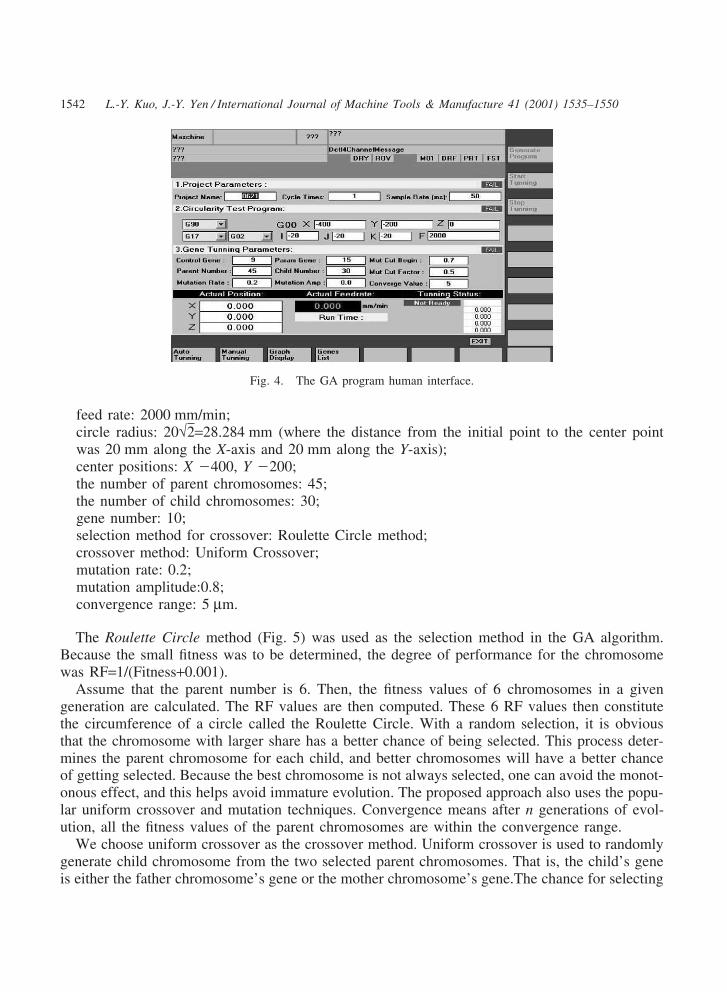
The experiment data obtained were stored in the PC. It took 24 generations to achieve conver-gence. A VB program is designed to implement the GA and transmission functions. Fig. 4 showsthe operation display of the GA software.
The steps in the experiment were as follows:
1. Assign the feed rate (speed) of circular motion on the XY plane of the 5-axis machine.2. Assign the center position of circular motion.3. Assign the number of the parent chromosomes and that of child chromosomes.4. Initialize randomly the gene values of the parent chromosomes of the first generation.5. Begin evolution (crossover, mutation and selection).6. Repeat step 5 until all the fitness values of the parent chromosomes fall below the conver-
gence value.7. End evolution.
The Experiment A conditioning data were as follows.
1542 L.-Y. Kuo, J.-Y. Yen / International Journal of Machine Tools & Manufacture 41 (2001) 1535–1550
Fig. 4. The GA program human interface.
feed rate: 2000 mm/min;circle radius: 20√2=28.284 mm (where the distance from the initial point to the center pointwas 20 mm along the X-axis and 20 mm along the Y-axis);center positions: X �400, Y �200;the number of parent chromosomes: 45;the number of child chromosomes: 30;gene number: 10;selection method for crossover: Roulette Circle method;crossover method: Uniform Crossover;mutation rate: 0.2;mutation amplitude:0.8;convergence range: 5 µm.
The Roulette Circle method (Fig. 5) was used as the selection method in the GA algorithm.Because the small fitness was to be determined, the degree of performance for the chromosomewas RF=1/(Fitness+0.001).
Assume that the parent number is 6. Then, the fitness values of 6 chromosomes in a givengeneration are calculated. The RF values are then computed. These 6 RF values then constitutethe circumference of a circle called the Roulette Circle. With a random selection, it is obviousthat the chromosome with larger share has a better chance of being selected. This process deter-mines the parent chromosome for each child, and better chromosomes will have a better chanceof getting selected. Because the best chromosome is not always selected, one can avoid the monot-onous effect, and this helps avoid immature evolution. The proposed approach also uses the popu-lar uniform crossover and mutation techniques. Convergence means after n generations of evol-ution, all the fitness values of the parent chromosomes are within the convergence range.
We choose uniform crossover as the crossover method. Uniform crossover is used to randomlygenerate child chromosome from the two selected parent chromosomes. That is, the child’s geneis either the father chromosome’s gene or the mother chromosome’s gene.The chance for selecting

1543L.-Y. Kuo, J.-Y. Yen / International Journal of Machine Tools & Manufacture 41 (2001) 1535–1550
Fig. 5. Roulette Circle method.
the farther of the mother is equal and the method is applied to each gene. For example, if achromosome contain 5 genes, then we randomly generate the binary array as follows:
Because the first binary value is 0, the first gene is chosen to be the gene from the fatherchromosome. The second binary value is 1, so the second gene come from the mother chromo-some, and so on. This is called uniform crossover, and it was the method adopted.
This ends the evolution. The flow chart of the GA program is shown in Fig. 6.The programflow chart is explained in detail in the following.
A. Initializing chromosomes means to assign random parameters values to the chromosomes. Inrandom initialization, limitations for maximum and minimum values are given for each motioncontrol parameter.
B. Checking fitness means computing the machine circular positioning errors defined by theformula in the previous section. Getting a new parent generation means to get in good childchromosomes and push out bad parent chromosomes. The pool always keeps the same numberof chromosomes.
C. Checking parent convergence means the fitness values of all the chromosomes are within apreset value.
D. If the current chromosomes are not satisfactory, the evolution should continue. Selection usesthe Roulette Circle to choose chromosomes for gene crossover and gene mutation.
In the experiment results, Pxx represents the xxth chromosome. The results are sorted and listedfrom the best chromosome (P1) to the worst chromosome (P45). The following table shows thephysical meaning of each gene (Table 2).
The first generation parent genes were generated randomly. Take parameter 9 (the X-axis pos-ition gain) and parameter 10 (the Y-axis position gain) as an example, Fig. 7 shows the theirinitial values. Fig. 7 also shows the corresponding fitness values. The 45 chromosomes are sorted

1544 L.-Y. Kuo, J.-Y. Yen / International Journal of Machine Tools & Manufacture 41 (2001) 1535–1550
Fig. 6. The GA algorithm.
Table 2Physical meaning of the genes
1 X-axis friction compensation time constant2 Y-axis friction compensation time constant3 X-axis friction compensation constant maximum value4 Y-axis friction compensation constant maximum value5 X-axis velocity feedforward weight6 Y-axis velocity feedforward weight7 X-axis dynamic match time constant (unit: ms)8 Y-axis dynamic match time constant (unit: ms)9 X-axis position control loop P gain10 Y-axis position control loop P gain
from best, number 1, to worse, number 45. The values vary from 2.3 to 73.9. One observes nosignificant correlation between the gene values and the fitness values. Experience tells us, how-ever, that the position loop gains should play an important role in the machine servo performance.This is explained by the fact that all the genes are generated randomly, therefore their correspond-ing fitness values can vary widely.
Evolution includes selection, crossover, mutation, fitness evaluation, and competition to producethe next generation of parent chromosomes. The number of parents is 45 and they produce 30children. With this choice, it can take some hours for evolution to finish. The numbers of the

1545L.-Y. Kuo, J.-Y. Yen / International Journal of Machine Tools & Manufacture 41 (2001) 1535–1550
Fig. 7. Initial chromosome and fitness.
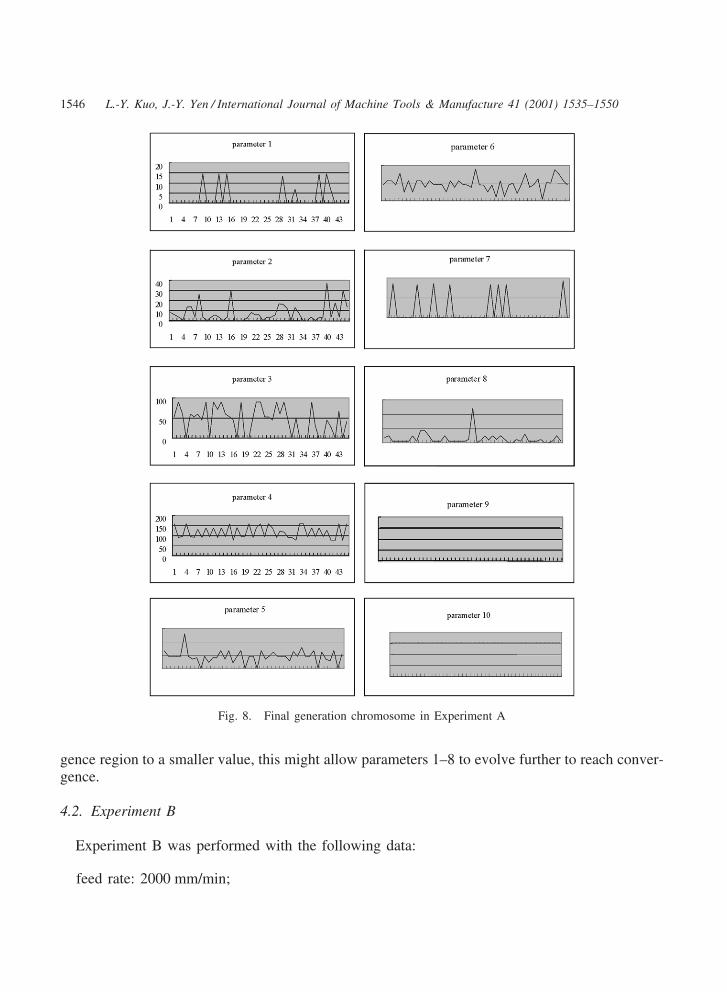
parents and the children cannot be further reduced because reduced population also reduced thechance to generate good children. The convergence range in experiment A is 5 µ, and the goalis achieved after 24 generations of evolution. Fig. 8 shows the resulting chromosomes in thefinal generation.
The GA tuning result from Experiment A is a very good result. Basically, the control resultobtained by a very experienced CNC servo engineer with the help of the CNC controller tuningtool can have an average following error of 5.6 µ. The result obtained using the proposed GAtuning approach is 2.3 µ, an obvious improvement. Notice that this is the result obtained using acommercial CNC machine. The prospects for future implementation are very good.
After evolution, the 9th gene and 10th gene of the final chromosomes (the X and Y positionloop gains) all converge to 3.0621 and 3.1030. The other genes values can vary greatly. Thisleads the authors to suspect that these two genes play a dominant role in the fitness function.This is not saying that these genes are “absolutely dominant” because one might design a differentfitness algorithm. Notice that the convergence range was set to 5 µ, and that parameters 1–8 gaverise only to very small changes in the fitness value (in the circular test); thus, only parameters 9and 10 converged to certain values and other parameters did not. The other parameters (1–8) didnot have any opportunity to “evolve” so as to converge to a certain value. If one sets the conver-
1546 L.-Y. Kuo, J.-Y. Yen / International Journal of Machine Tools & Manufacture 41 (2001) 1535–1550
Fig. 8. Final generation chromosome in Experiment A
gence region to a smaller value, this might allow parameters 1–8 to evolve further to reach conver-gence.
4.2. Experiment B
Experiment B was performed with the following data:
feed rate: 2000 mm/min;
1547L.-Y. Kuo, J.-Y. Yen / International Journal of Machine Tools & Manufacture 41 (2001) 1535–1550
circle radius: 20√2=28.24 mm (where the distance from initial point to the center point is 20 mmalong X-axis and 20 mm along Y-axis);center positions: X �400, Y �200;the number of parent chromosomes: 45;the number of child chromosomes: 30;gene number: 10;selection method in crossover: the Roulette Circle method;crossover method: Uniform Crossover;mutation rate: 0.3;mutation amplitude: 0.8;convergence range: 5 µ.
In this experiment, all the parameters were the same as in Experiment A except that the mutationrate was increased to 0.3. The evolution of this process took 17 generations. It is interesting tonote that the fitness of the chromosomes in the final generation showed a large range of variation(ranging from 2.39 to 4.76 µ instead of 2.34 to 3.2 µ in Experiment A).
4.3. Experiment C
In an effort to resolve the problem of “bad convergence quality” due to the large variation inthe fitness value, this research employed a new method in Experiment C, a “dynamic mutationamplitude” method. Experiment C was conducted under the same conditions studied in Experi-ment B except that the mutation rate was set to 0.3 and the mutation amplitude started at 0.8 andwas reduced to 0.4 after 70% of the chromosomes were within convergence range (the conver-gence range was still set to 5 µ). The idea was to reduce the frequency of mutation when a largeportion of the chromosomes had shifted to a good “trend” toward evolution. This could also beregarded as a slow down in evolution when the final goal was close.
Experiment C took 19 generations to converge. This was 5 generations faster than ExperimentA but 2 generations slower than Experiment B. However, as expected, this result was obtainedat the expense of slightly slower convergence; the convergence values now ranged from 2.19to 3.595 µ.
4.4. Further experiments
In the fourth experiment, the machine was run at a higher feed rate. The results obtained couldbe useful for high-speed machine applications. For actual machining implementations, differentparameter sets could be combined together and switched on line to match different machiningprocesses. In this experiment, the feed rate was set to 5000 mm/min, and the convergence rangewas relaxed to 10 µ. Convergence took 27 generations. It is reasonable that evolution was moredifficult because the higher feed rate induced stronger nonlinear effects and disturbances in thesystem. The command frequency was higher, and more unpleasant high frequency characteristicsof the plant were excited. Parameters 9 and 10 converged to 3.5143 and 3.7598, respectively.The gains were higher but the tendency of the Y-axis to require higher gain was still observed(the Y-axis had greater inertia).
1548 L.-Y. Kuo, J.-Y. Yen / International Journal of Machine Tools & Manufacture 41 (2001) 1535–1550
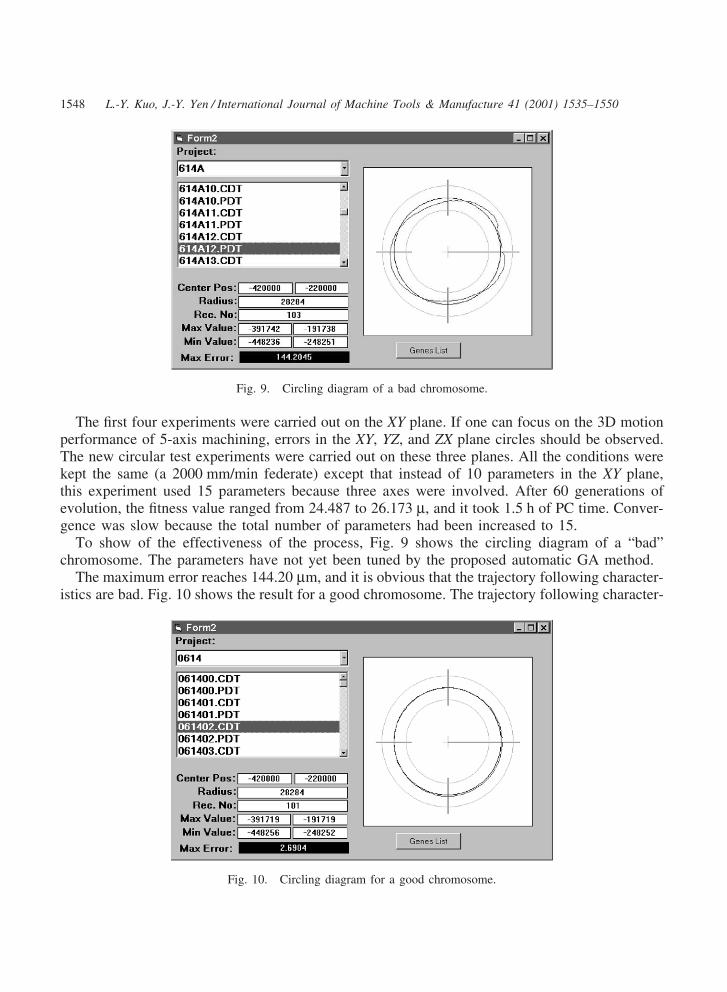
Fig. 9. Circling diagram of a bad chromosome.
The first four experiments were carried out on the XY plane. If one can focus on the 3D motionperformance of 5-axis machining, errors in the XY, YZ, and ZX plane circles should be observed.The new circular test experiments were carried out on these three planes. All the conditions werekept the same (a 2000 mm/min federate) except that instead of 10 parameters in the XY plane,this experiment used 15 parameters because three axes were involved. After 60 generations ofevolution, the fitness value ranged from 24.487 to 26.173 µ, and it took 1.5 h of PC time. Conver-gence was slow because the total number of parameters had been increased to 15.
To show of the effectiveness of the process, Fig. 9 shows the circling diagram of a “bad”chromosome. The parameters have not yet been tuned by the proposed automatic GA method.
The maximum error reaches 144.20 µm, and it is obvious that the trajectory following character-istics are bad. Fig. 10 shows the result for a good chromosome. The trajectory following character-
Fig. 10. Circling diagram for a good chromosome.
1549L.-Y. Kuo, J.-Y. Yen / International Journal of Machine Tools & Manufacture 41 (2001) 1535–1550
istics have clearly improved, and the maximum error is now reduced to 2.69 µm. As explainedabove, an experienced servo engineer can tune the parameters to the 5.6 µm level, and the pro-posed method can always achieve error less than 3 µm error.
5. Conclusions
This research used the self-designed PC-Based controller based on the Siemens 840D kernelas a test bench to implement an automatic GA based parameter-tuning algorithm. Through theevolution of genes (where each gene represents a parameter), the controller gradually adapted toachieve better control performance. The experiment results serve as a good reference for extractingthe most important parameters for the controller. The experiments were carried out under differentconditions to examine the convergence properties. To improve on convergence, a dynamicmutation amplitude method was introduced. The results obtained in these experiments indicatethat the GA algorithm was able to achieve expert level performance. The control results weresuperior to the results obtained for a controller tuned by a trained expert.
Acknowledgements
This project is supported in part by the Industrial Technology Research Institute, ROC, underproject number 893K51AQ2, which is a subcontract from the Ministry of Economic Affairs, ROC,and in part by the National Science Council under project number NSC 89-TPC-7-002-008.
References
[1] G. Younkin, Modeling machine tool feed servo drives using simulation techniques to predict performance, Confer-ence Record of the Industry Applications Society Annual Meeting, vol. 2, 1989, pp. 1699–1706.
[2] D.M. Alter, Tsu-Chin Tsao, Dynamic stiffness enhancement of direct linear motor feed drives for machining, in:Proceedings of the 1994 American Control Conference, vol. 3, 1994, pp. 3303–3307.
[3] B.K. Choi, C.H. Choi, H. Lim, Model-based disturbance attenuation for CNC machining centers in cutting process,IEEE/ASME Transactions on Mechatronics 4 (2) (1999) 157–168.
[4] J.F. Cuttino, A.C. Miller Jr., D.E. Schinstock, Performance optimization of a fast tool servo for single-pointdiamond turning machines, IEEE/ASME Transactions on Mechatronics 4 (2) (1999) 169–179.
[5] A. Arakawa, K. Miyata, Simultaneous optimization algorithm for determining both mechanical-system and control-ler parameters for positioning control mechanisms, in: Proceedings of the 1996 fourth International Workshop onAdvanced Motion Control, AMC’96, 18–21 March 1996, v2 Tsu, Japan, part 2, pp. 625–630.
[6] B.-X. Xiao, The main control mode and fuzzy control strategy of CNC system for gear hobbing and grindingmachine, Proceedings of the IEEE International Conference on Industrial Technology, 1996, pp. 643–646.
[7] J. Liu, K. Yamazaki, Y. Yokoyama, Dynamic gain motion control with multi-axis trajectory monitoring formachine tool systems, in: Proceedings of the 1998 International Workshop on Advanced Motion Control, AMC’98,1998, pp. 316–321.
[8] J. Liu, K. Yamazaki, Y. Yokoyama, Dynamic gain motion control with multi-axis trajectory monitoring formachine tool systems, in: Proceedings of the 1998 International Workshop on Advanced Motion Control, AMC’98,1998, pp. 316–321.

1550 L.-Y. Kuo, J.-Y. Yen / International Journal of Machine Tools & Manufacture 41 (2001) 1535–1550
[9] R.J. Fornaro, T.A. Dow, A high-performance machine tool controller, in: Conference Record of the 1988 IEEEIndustry Applications Society Annual Meeting, vol. 2, 1988, pp. 1429–1439
[10] P. Wang, D.P. Kwok, Optimal design of PID process controllers based on genetic algorithms, Control EngineeringPractice 2 (4) (1994) 641–648.
[11] C.-J. Wu, C.-H. Huang, A hybrid method for parameter tuning of PID controllers, Journal of the Franklin Institute334 (4) (1997) 547–562.
[12] S.-C. Lin, Y.-Y. Chen, Design of self-learning fuzzy sliding mode controllers based on genetic algorithms, FuzzySets and Systems 86 (2) (1997) 139–153.
[13] H. Ishigami, Y. Hasegawa, T. Fukuda, T. Shibata, Takanori, Automatic generation of hierarchical structure offuzzy inference by genetic algorithm, in: Proceedings of the 1994 IEEE International Conference on Neural Net-works, 27–29 June 1994, v3 Orlando, FL, USA, part 3, pp. 1566–1570.
[14] L. Wang, J. Yen, Extracting fuzzy rules for system modeling using a hybrid of genetic algorithms and Kalmanfilter, Fuzzy Sets and Systems 101 (3) (1999) 353–362.
[15] A. Tesar, M. Drzik, Genetic algorithms for dynamic tuning of structures, Computers and Structures 57 (2) (1995)287–295.
[16] S.V. Ulyanov, K. Yamafuji, K. Miyagawa, T. Tanaka, T. Fukuda, Intelligent fuzzy motion control of mobile robotfor service use, in: Proceedings of the 1995 IEEE/RSJ International Conference on Intelligent Robots and Systems,5–9 August 1995, v3 Pittsburgh, PA, USA, part 3, pp. 486–489.
[17] E.W. McGookin, D.J. Murray-Smith, Y. Li, T.I. Fossen, Ship steering control system optimisation using geneticalgorithms, Control Engineering Practice 8 (4) (2000) 429–443.
[18] T.S. Wu, J.C. Liu, Fuzzy control of rider–motorcycle system using genetic algorithm and auto-tuning, Mechatron-ics 5 (4) (1995) 441–455.
[19] Y.S. Tarng, H.Y. Chuang, W.T. Hsu, Intelligent cross-coupled fuzzy feedrate controller design for CNC machinetools based on genetic algorithms, International Journal of Machine Tools and Manufacture 39 (10) (1999)1673–1692.