Embed Size (px)
Citation preview
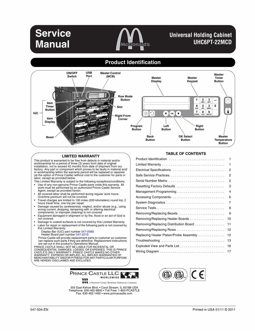
Universal Holding CabinetUHC6PT-22MCD
547-504-EN Printed in USA 01/11 © 2011
ServiceManual
Product Identification
OK
21 3ABC DEF
24 3 0JKLGHI MNO
87 9TUVPQRS WXYZ
ON/OFF Switch
Item Timer Button
Item Display
Slot
Row Mode Button
Master Control (MCB)
Left Button
Master Display
Master Keypad
Master Timer Button
Master Temperature
Button
Right Button
OK Select Button
Back Button
Program Button
USB Port
Bezel
Right Front Corner
IUC
TABLE OF CONTENTSProduct Identification . . . . . . . . . . . . . . . . . . . . . . . . . . . . . . 1
Limited Warranty . . . . . . . . . . . . . . . . . . . . . . . . . . . . . . . . . . 1
Electrical Specifications . . . . . . . . . . . . . . . . . . . . . . . . . . . . 2
Safe Service Practices. . . . . . . . . . . . . . . . . . . . . . . . . . . . . . 2
Serial Number Matrix . . . . . . . . . . . . . . . . . . . . . . . . . . . . . . . 2
Resetting Factory Defaults . . . . . . . . . . . . . . . . . . . . . . . . . . 3
Management Programming . . . . . . . . . . . . . . . . . . . . . . . . . . 4
Accessing Components . . . . . . . . . . . . . . . . . . . . . . . . . . . . . 6
System Diagnostics . . . . . . . . . . . . . . . . . . . . . . . . . . . . . . . . 7
Service Tests . . . . . . . . . . . . . . . . . . . . . . . . . . . . . . . . . . . . . 8
Removing/Replacing Bezels . . . . . . . . . . . . . . . . . . . . . . . . . 9
Removing/Replacing Heater Boards . . . . . . . . . . . . . . . . . . . 10
Removing/Replacing Distribution Board . . . . . . . . . . . . . . . . 11
Removing/Replacing Rows . . . . . . . . . . . . . . . . . . . . . . . . . . 12
Replacing Heater Platen/Probe Assembly. . . . . . . . . . . . . . . 12
Troubleshooting . . . . . . . . . . . . . . . . . . . . . . . . . . . . . . . . . . 13
Exploded View and Parts List . . . . . . . . . . . . . . . . . . . . . . . . 16
Wiring Diagram . . . . . . . . . . . . . . . . . . . . . . . . . . . . . . . . . . . 17
LIMITED WARRANTYThis product is warranted to be free from defects in material and/or workmanship for a period of three (3) years from date of original installation, not to exceed 42 months from date of shipment from our factory. Any part or component which proves to be faulty in material and/or workmanship within the warranty period will be replaced or repaired (at the option of Prince Castle) without cost to the customer for parts or labor, except as provided below. This Limited Warranty is subject to the following exceptions/conditions:• Use of any non-genuine Prince Castle parts voids this warranty. All
work must be performed by an authorized Prince Castle Service Agent, except as provided herein.
• All covered labor shall be performed during regular work hours. Overtime premium will not be covered.
• Travel charges are limited to 100 miles (200 kilometers) round trip; 2 hours travel time, one trip per repair.
• Damage caused by carelessness, neglect, and/or abuse (e.g., using wrong current, dropping, tampering with or altering electrical components, or improper cleaning) is not covered.
• Equipment damaged in shipment or by fire, flood or an act of God is not covered.
• Damage to coated surfaces is not covered by this Limited Warranty.• Labor for repair or replacement of the following parts is not covered by
this Limited Warranty: Display Bar (IUC) part number 547-058SHeater Board part number 547-221S
Prince Castle will provide replacement parts to customer so customer can replace such parts if they are defective. Replacement instructions are set out in the product’s Operations Manual.
PRINCE CASTLE SHALL NOT BE LIABLE FOR INCIDENTAL OR CONSEQUENTIAL DAMAGES, LOSSES, OR EXPENSES. THIS IS PRINCE CASTLE’S ONLY WARRANTY. PRINCE CASTLE MAKES NO OTHER WARRANTY, EXPRESS OR IMPLIED. ALL IMPLIED WARRANTIES OF MERCHANTABILITY AND/OR FITNESS FOR ANY PARTICULAR PURPOSE ARE HEREBY DISCLAIMED AND EXCLUDED.
PRINCE CASTLE LLC WORLDW IDE
355 East Kehoe Blvd. • Carol Stream, IL 60188 USATelephone: 630-462-8800 • Toll Free: 1-800-PCASTLE
Fax: 630-462-1460 • www.princecastle.com
Printed in USA 01/11 © 2011 2 547-504-EN
Universal Holding CabinetUHC6PT-22MCD
PRINCE CASTLE LLC WORLDW IDE
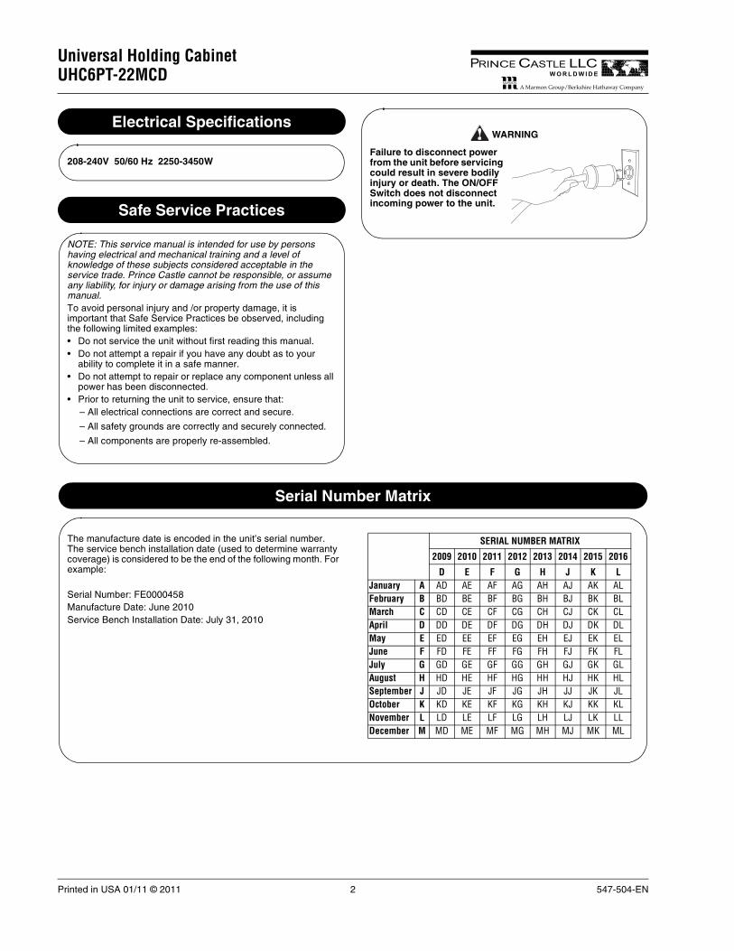
Electrical Specifications
208-240V 50/60 Hz 2250-3450W
Safe Service Practices
NOTE: This service manual is intended for use by persons having electrical and mechanical training and a level of knowledge of these subjects considered acceptable in the service trade. Prince Castle cannot be responsible, or assume any liability, for injury or damage arising from the use of this manual.To avoid personal injury and /or property damage, it is important that Safe Service Practices be observed, including the following limited examples:• Do not service the unit without first reading this manual.• Do not attempt a repair if you have any doubt as to your
ability to complete it in a safe manner.• Do not attempt to repair or replace any component unless all
power has been disconnected.• Prior to returning the unit to service, ensure that:
– All electrical connections are correct and secure.
– All safety grounds are correctly and securely connected.
– All components are properly re-assembled.
Failure to disconnect power from the unit before servicing could result in severe bodily injury or death. The ON/OFF Switch does not disconnect incoming power to the unit.
WARNING
Serial Number Matrix
The manufacture date is encoded in the unit’s serial number. The service bench installation date (used to determine warranty coverage) is considered to be the end of the following month. For example:
Serial Number: FE0000458Manufacture Date: June 2010Service Bench Installation Date: July 31, 2010
SERIAL NUMBER MATRIX
2009 2010 2011 2012 2013 2014 2015 2016
D E F G H J K LJanuary A AD AE AF AG AH AJ AK ALFebruary B BD BE BF BG BH BJ BK BLMarch C CD CE CF CG CH CJ CK CLApril D DD DE DF DG DH DJ DK DLMay E ED EE EF EG EH EJ EK ELJune F FD FE FF FG FH FJ FK FLJuly G GD GE GF GG GH GJ GK GLAugust H HD HE HF HG HH HJ HK HLSeptember J JD JE JF JG JH JJ JK JLOctober K KD KE KF KG KH KJ KK KLNovember L LD LE LF LG LH LJ LK LLDecember M MD ME MF MG MH MJ MK ML
547-504-EN 3 Printed in USA 01/11 © 2011
Universal Holding CabinetUHC6PT-22MCD
PRINCE CASTLE LLC WORLDW IDE
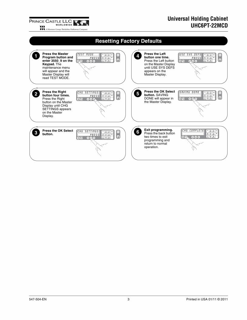
Resetting Factory Defaults
Press the Master Program button and enter 3550_9 on the Keypad. The maintenance menu will appear and the Master Display will read TEST MODE.
OK
21 3ABC DEF
24 3 0JKLGHI MNO
87 9TUVPQRS WXYZ
t e s t m o d e
p r e s s1
Press the Right button four times. Press the Right button on the Master Display until CHG SETTINGS appears on the Master Display.
OK
21 3ABC DEF
24 3 0JKLGHI MNO
87 9TUVPQRS WXYZ
c h g s e t t i n g s
p r e s s2
Press the OK Select button.
OK
21 3ABC DEF
24 3 0JKLGHI MNO
87 9TUVPQRS WXYZ
c h g s e t t i n g s
p r e s s3
Press the Left button one time. Press the Left button on the Master Display until USE SYS DEFS appears on the Master Display.
OK
21 3ABC DEF
24 3 0JKLGHI MNO
87 9TUVPQRS WXYZ
u s e s y s d e f s
p r e s s4
Press the OK Select button. SAVING DONE will appear in the Master Display.
OK
21 3ABC DEF
24 3 0JKLGHI MNO
87 9TUVPQRS WXYZ
s a v i n g d o n e
5
Exit programming. Press the back button two times to exit programming and return to normal operation.
OK
21 3ABC DEF
24 3 0JKLGHI MNO
87 9TUVPQRS WXYZ
C H G C O M P L E T E6

Printed in USA 01/11 © 2011 4 547-504-EN
Universal Holding CabinetUHC6PT-22MCD
PRINCE CASTLE LLC WORLDW IDE
Management Programming
Press the Master Program button. The Master Display will request your password. NOTE: The default password is “1955”.
1
Enter your password. Type your password in on the keypad and press the OK Select button. Programmable categories will appear in the rows of Item Displays, reading from the left.
2
Choose a programmable category. Press the lit Item Timer button to the left of the category you wish to program. Follow the instructions on the Master Display to navigate and program the UHC.Confirm selections by pressing the OK Select button.
Press the Back button to retreat one level of programming (press several times to exit programming).
m o d e s
m e n u s
p r
OK
21 3ABC DEF
24 3 0JKLGHI MNO
87 9TUVPQRS WXYZ
p r o g r a m
OK
21 3ABC DEF
24 3 0JKLGHI MNO
87 9TUVPQRS WXYZ
C H G C O M P L E T E
3
The first programmable category is MODES. Sets the entire UHC to one of the different daypart modes, Breakfast, Change Over, Regular, Custom 1, Custom 2, or Cleaning. Each of the dayparts modes is displayed. Press the button next to the desired daypart mode and then press the OK Select button on the Master Control Panel. Press the Back button on the Master Control Panel twice to exit programming.
b r k fst
CH G O V E R
R E G M E N U
C U STO M 1
C U STO M 2
M o
S E
4
The second programmable category is MENUS. Sets which food product is assigned to each tray in each of the daypart modes. Press the button next to the daypart mode whose menu is to change. The name of the food product currently assigned to each tray position is displayed. Pressing the button next to the desired tray position cycles through the available food products that can be assigned to the tray position. When the desired food product is displayed, press the OK Select button on the Master Control Panel. You can change more than one item before confirming by pressing OK Select.
NOTE: Be sure to start with the left-most Item Display in each row, because changing an item may also make changes to items to the right in that row due to temperature restrictions.
b r k fst
CH G O V E R
R E G M E N U
C U STO M 1
C U STO M 2
M e
S E
bag e l
fo l d e g g
M c g r i d d l
M c g r i d d l
r n d e g g
B RS A
5

547-504-EN 5 Printed in USA 01/11 © 2011
Universal Holding CabinetUHC6PT-22MCD
PRINCE CASTLE LLC WORLDW IDE
Management Programming (continued)
The third programmable category is ITEMS. Press the button next to the task to be performed, add a food product, change a product’s parameters, or delete a food product from the UHC’s product library. You can set the item’s Name, Top Temperature, Bottom Temperature, Hold Time and Cook-Now Time.
a d d i t e m
CH G i t e m
d e l i t e m
i t
S E
6
The fourth programmable category is LOCALE. Choose the language for the displays and whether temperatures are reported in Fahrenheit or Celsius.Press the button next to LANGUAGE and a list of available languages appears. Press the button next to the desired language and then the OK Select button. Press the Back button twice to exit language selection or additional times to exit programming.Press the button next to DEGREES to select between Celsius and Fahrenheit. Press the button next to the desired temperature units and then the OK Select button. Press the Back button twice to exit language selection or additional times to exit programming.
OK
21 3ABC DEF
24 3 0JKLGHI MNO
87 9TUVPQRS WXYZ
engl ishlanguage
fahrenhtdegrees
l o c a l e
g
7
The last programmable category is SOUND. Choose how loud the alarms are. There are four sound levels plus silent. Press the button next to the desired sound level and the OK Select button. Press the Back button three times to exit programming.
c u r r e
l e v e l 1
l e v e l 2
l e v e l 3
l e v e l 4
s i l e n t
s o
S E
8

Printed in USA 01/11 © 2011 6 547-504-EN
Universal Holding CabinetUHC6PT-22MCD
PRINCE CASTLE LLC WORLDW IDE
Accessing Components
Row Display Board
Lid
Power Supply
Fans
Filter Rear Right Corner
Front Right Corner
Power Cord
SpeakerRelay
Fuse Box and Fuses
Terminal Block
Distribution Board
Right Side Panel
Heater Boards
Front Left Corner
Master Display Board
Failure to disconnect power from the unit before servicing could result in severe bodily injury or death. The ON/OFF Switch does not disconnect incoming power to the unit.
WARNING
Unplug the unit.1
Remove the right front corner.a. Remove the screw from the base of the corner.
b. Tilt the corner up and remove.
2
Remove the lid.a. Remove the 4 screws on the top of the unit.
b. Lift the lid off of the unit.
3
Remove the right side panel.a. Lift the panel up and remove.4
547-504-EN 7 Printed in USA 01/11 © 2011
Universal Holding CabinetUHC6PT-22MCD
PRINCE CASTLE LLC WORLDW IDE
System Diagnostics
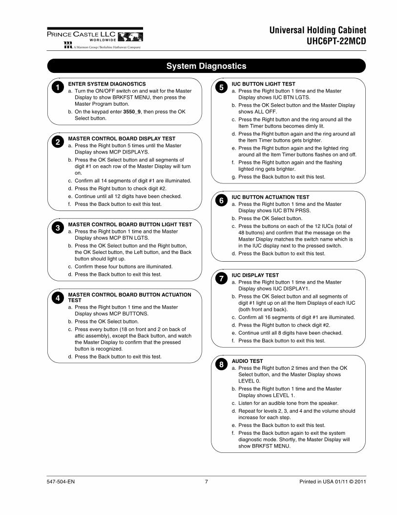
ENTER SYSTEM DIAGNOSTICSa. Turn the ON/OFF switch on and wait for the Master
Display to show BRKFST MENU, then press the Master Program button.
b. On the keypad enter 3550_9, then press the OK Select button.
1
MASTER CONTROL BOARD DISPLAY TESTa. Press the Right button 5 times until the Master
Display shows MCP DISPLAYS.
b. Press the OK Select button and all segments of digit #1 on each row of the Master Display will turn on.
c. Confirm all 14 segments of digit #1 are illuminated.
d. Press the Right button to check digit #2.
e. Continue until all 12 digits have been checked.
f. Press the Back button to exit this test.
2
MASTER CONTROL BOARD BUTTON LIGHT TESTa. Press the Right button 1 time and the Master
Display shows MCP BTN LGTS.
b. Press the OK Select button and the Right button, the OK Select button, the Left button, and the Back button should light up.
c. Confirm these four buttons are illuminated.
d. Press the Back button to exit this test.
3
MASTER CONTROL BOARD BUTTON ACTUATION TEST a. Press the Right button 1 time and the Master
Display shows MCP BUTTONS.
b. Press the OK Select button.
c. Press every button (18 on front and 2 on back of attic assembly), except the Back button, and watch the Master Display to confirm that the pressed button is recognized.
d. Press the Back button to exit this test.
4
IUC BUTTON LIGHT TEST a. Press the Right button 1 time and the Master
Display shows IUC BTN LGTS.
b. Press the OK Select button and the Master Display shows ALL OFF.
c. Press the Right button and the ring around all the Item Timer buttons becomes dimly lit.
d. Press the Right button again and the ring around all the Item Timer buttons gets brighter.
e. Press the Right button again and the lighted ring around all the Item Timer buttons flashes on and off.
f. Press the Right button again and the flashing lighted ring gets brighter.
g. Press the Back button to exit this test.
5
IUC BUTTON ACTUATION TEST a. Press the Right button 1 time and the Master
Display shows IUC BTN PRSS.
b. Press the OK Select button.
c. Press the buttons on each of the 12 IUCs (total of 48 buttons) and confirm that the message on the Master Display matches the switch name which is in the IUC display next to the pressed switch.
d. Press the Back button to exit this test.
6
IUC DISPLAY TESTa. Press the Right button 1 time and the Master
Display shows IUC DISPLAY1.
b. Press the OK Select button and all segments of digit #1 light up on all the Item Displays of each IUC (both front and back).
c. Confirm all 16 segments of digit #1 are illuminated.
d. Press the Right button to check digit #2.
e. Continue until all 8 digits have been checked.
f. Press the Back button to exit this test.
7
AUDIO TESTa. Press the Right button 2 times and then the OK
Select button, and the Master Display shows LEVEL 0.
b. Press the Right button 1 time and the Master Display shows LEVEL 1.
c. Listen for an audible tone from the speaker.
d. Repeat for levels 2, 3, and 4 and the volume should increase for each step.
e. Press the Back button to exit this test.
f. Press the Back button again to exit the system diagnostic mode. Shortly, the Master Display will show BRKFST MENU.
8

Printed in USA 01/11 © 2011 8 547-504-EN
Universal Holding CabinetUHC6PT-22MCD
PRINCE CASTLE LLC WORLDW IDE
Service Tests
POWER SUPPLY TESTa. Disconnect power and inspect all terminals and
connections for loose wires.
b. Reconnect power and check for 5V DC on output pins of the power supply (orange wires = +V, black wires = GND).
c. If 5V DC is not on the output pins of the power supply, turn power off, disconnect the output connector, turn power back on and check the voltage between the same two pins as in the previous step.
1
HEATER BOARD TESTa. Disconnect power and ensure heater board
connectors are fully engaged with the receptacles on the bus board.
b. Apply power and check for line voltage between pins 1 and 2 on connector P3.
c. Check for 5V DC between pins 1 and 10 on connector P2.
d. Check the operation of each triac on the heater board by checking the voltage between the following pins:
Triac Q1 = Pins 2 and 3
Triac Q3 = Pins 2 and 4
Triac Q6 = Pins 2 and 5
Triac Q9 = Pins 2 and 6
Triac Q11 = Pins 2 and 7
Triac Q13 = Pins 2 and 8
If the voltage reading switches between line voltage and no voltage, the triac is working correctly. If the voltage reading is steady at line voltage, the triac is not turning on. If the voltage reading is very small, the triac is turned on constantly.
2
DISPLAY TESTa. Move a ribbon cable from a display that is working
to a failed display to determine if the failed display is defective.
b. Reconnect all connections to original positions.
3
HEATER PLATEN TESTa. Disconnect power and disconnect the heater
connector from the bus board.
b. Measure resistance between the two pins in the heat connector. Resistance should be 190-220 ohms.
c. Incorrect resistance indicates a defective heater platen.
4

547-504-EN 9 Printed in USA 01/11 © 2011
Universal Holding CabinetUHC6PT-22MCD
PRINCE CASTLE LLC WORLDW IDE
Removing/Replacing Bezels
Unplug the unit.1
Failure to disconnect power from the unit before servicing could result in severe bodily injury or death. The ON/OFF Switch does not disconnect incoming power to the unit.
WARNING
Remove the screw. Remove the screw from the base of the front right corner if the bezel to be removed is on the front of the unit. If the bezel to be removed is on the back of the unit (the side without the Master Control), remove the screw from the base of the rear right corner.
2
Tilt the corner up and remove.
Right Front Corner
3
Slide the bezel toward the open corner and then pull outward. NOTE: The back side of the bezels should be wiped with a damp, clean towel once every three months.
4
If the bezel is being replaced, disconnect the ribbon cable and connect it to the replacement bezel.
Hole in Row
Ribbon Cable
Bezel
5
To reassemble, align the three plastic protrusions on the back of the bezel with the three holes in the row and push inward.
6
Slide the bezel toward the closed corner. The bezel should now line up with the other bezels at the open corner.
7
Reassemble the corner.8

Printed in USA 01/11 © 2011 10 547-504-EN
Universal Holding CabinetUHC6PT-22MCD
PRINCE CASTLE LLC WORLDW IDE
Removing/Replacing Heater Boards
Unplug the unit.1
Failure to disconnect power from the unit before servicing could result in severe bodily injury or death. The ON/OFF Switch does not disconnect incoming power to the unit.
WARNING
Remove the right front corner.2
Disconnect ribbon cables. Disconnect ribbon cables that may interfere with forward movement of the heater board being removed.
3
Lift both ejector tabs on the heater board to disconnect it from the bus board.
Ejector Tabs
Heater Board
4
Slide the heater board forward and out. Hold any connections out of the way while sliding the heater board so they don’t impede movement.
5
To reassemble, align the replacement heater board. The top and bottom of the heater board must be fit into the top and bottom grooves.
6
Slide the replacement heater board in and back. Hold any connections out of the way while sliding the heater board back in.
7
Reconnect the heater board to the bus board by firmly pushing on the ejector tabs. Make sure the board-to-board connectors are fully seated together.
8
Reconnect any disconnected ribbon cables.9
Reassemble the unit.10

547-504-EN 11 Printed in USA 01/11 © 2011
Universal Holding CabinetUHC6PT-22MCD
PRINCE CASTLE LLC WORLDW IDE
Removing/Replacing Distribution Board
Unplug the unit.1
Failure to disconnect power from the unit before servicing could result in severe bodily injury or death. The ON/OFF Switch does not disconnect incoming power to the unit.
WARNING
Disassemble the unit to access the distribution board. Remove the right front corner, lid and right side panel according to Accessing Components section.
DistributionBoard
2
Label and disconnect connections. NOTE: Be sure to label each of the 26 connections before disconnecting.
3
Remove both heater boards from the bus board.4
Remove screws. Remove and save the screws holding the distribution board to the unit.5
To reassemble, align the replacement distribution board.6
Replace the screws.7
Reattach both heater boards to the bus board.8
Reconnect connections. Using your labels as a guide, reconnect the 26 connections.9
Reassemble the unit.10

Printed in USA 01/11 © 2011 12 547-504-EN
Universal Holding CabinetUHC6PT-22MCD
PRINCE CASTLE LLC WORLDW IDE
Removing/Replacing Rows
Unplug the unit.1
Failure to disconnect power from the unit before servicing could result in severe bodily injury or death. The ON/OFF Switch does not disconnect incoming power to the unit.
WARNING
Disassemble the unit to access the faulty row. Remove the lid, both side panels, and all four corner pieces from the unit.
2
Label and disconnect connections. NOTE: Be sure to label each of the wires before disconnecting the row wires from the distribution board.
RowBezel Attachment Strip
Bezel
3
Access the faulty row. Remove the necessary bezels and the two bezel attachment strips on the top and bottom of the faulty row. Remove the four side bolts securing the row to the unit.
4
Remove the faulty row. Carefully slide the row out of the unit, feeding the attached wires through the row opening.
5
Replace the row. Align the replacement row and the unit. Carefully slide the insulation wrapped row into the unit, routing the wires through to the back of the unit.
6
Replace the screws. Replace and secure the four side bolts.7
Reconnect connections. Using your labels as a guide, reconnect the distribution board connections.8
Reassemble the unit. Reattach the bezel attachment strips, the bezels, the four corner pieces, both side panels and the lid.
9
Replacing Heater Platen/Probe Assembly
Remove the row. Disassemble the unit and remove the row according to Removing/Replacing Rows section.
1
Access the faulty heater platen. Slide the row from the heater insulation wrap. Remove the four setscrews attaching the faulty heater platen to the platen rail.
Heater Platens
Insulation Wrap
Setscrew
Platen Rails
2
Remove the heater platen. Carefully slide the platen out of the rail.3
Replace the heater platen. Align the replacement heater platen and the platen rail. Carefully slide the platen into the rail. Replace and secure the four setscrews. Neatly recover the row unit with the heater insulation wrap.
4
Reassemble the unit. Replace the row and reassemble the unit according to Removing/Replacing Rows section.
5

547-504-EN 13 Printed in USA 01/11 © 2011
Universal Holding CabinetUHC6PT-22MCD
PRINCE CASTLE LLC WORLDW IDE
Troubleshooting
MASTER DISPLAY MESSAGES
PROBLEM PROBABLE CAUSE SOLUTION
Left-most Item Display in affected row reads: HI TEMP
Row is changing to a temperature that is lower than its current value.
Wait for temperature to change before using slot.
Left-most Item Display in affected row reads: LOW TEMP
Row is changing to a temperature that is higher than its current value.
Wait for temperature to change before using slot.
Left-most Item Display in affected row reads: CALL SERVICEROW TEMP TOO HIGHand alarm sounds
Slot temperature is more than 10°F (6°C) above setpoint for more than 15 minutes.
• Using a stand-alone temperature meter, check the actual heater platen temperature and compare it to the displayed temperature.
• To make sure the heater is responding to the unit’s circuits, press that row’s Row Mode button until OFF appears in the Item Displays and press the OK Select button. Then press the Row Mode button until an active mode appears and press OK Select.
• Heater platen may be defective — refer to Heater Platen Test.
Left-most Item Display in affected row reads: CALL SERVICEROW TEMP TOO COOL and alarm sounds
Slot temperature is more than 10°F (6°C) below setpoint for more than 15 minutes.
Left-most Item Display in affected row reads: CALL SERVICE TEMP SENSOR ERROR and alarm sounds
There is a problem with the temperature probe.
• Inspect the probe’s ribbon cable connection.• Replace probe — refer to Replacing Heater Platen/Probe
Assembly.
Left-most Item Display in affected row reads: CALL SERVICE RATE OF RISE and alarm sounds
A row is taking longer than 30 minutes to reach minimum temperature — there is a problem with the temperature probe or heater in row.
• Turn the ON/OFF switch off and on to clear any software problem.
• To make sure the heater is responding to the unit’s circuits, press that row’s Row Mode button until OFF appears in the Item Displays and press the OK Select button. Then press the Row Mode button until an active mode appears and press OK Select.
• Heater platen may be defective — refer to Heater Platen Test.• Move a probe lead from a row that is working to this failed row
to determine if a probe is defective.• Replace probe — refer to Replacing Heater Platen/Probe
Assembly.
Master Display reads: CALL SERVICE DISTRIBUTION BOARD ERROR and alarm sounds
Heaters for 3 rows will not operate — distribution board is down.
• Turn the ON/OFF switch off and on to clear any software problem.
• Inspect the board’s ribbon cable connections.
Master Display reads:CALL SERVICE ROW DISPLAY BOARD ERROR and alarm sounds
One of the Item Displays is not operating.
OTHER FAILURE CONDITIONS
PROBLEM PROBABLE CAUSE SOLUTION
Unit will not turn on and fans don’t run
There is an exterior power supply problem.
• Check for line voltage at the ON/OFF switch and the transformer.
• Reset the circuit breaker.
While turned on, one display won’t light
There is a problem with the ribbon cable or display.
• Inspect the display’s ribbon cable connection.• Move a ribbon cable from a display that is working to this failed
display to determine if this display is defective.
While turned on, all displays won’t light
There is an internal power supply problem.
• Check for 5V DC on output pins of the power supply — refer to Power Supply Test.
While turned on, one row will not heat or heats improperly
There is a problem with that row’s heater board, heater platen or probe.
• Make sure that leads and inputs are securely seated on the heater boards.
• Perform Heater Board Test.• Move power leads from a row that is working to this failed row to
determine if this heater is defective.• Move a probe lead from a row that is working to this failed row
to determine if a probe is defective.
Printed in USA 01/11 © 2011 14 547-504-EN
Universal Holding CabinetUHC6PT-22MCD
PRINCE CASTLE LLC WORLDW IDE
UHC IN STORE TROUBLESHOOTING
SYMPTOM RECOGNITION
Item Displays on a timer bar are blank and there is no error message on the Master Display.
A
Parts of the displayed characters on a timer bar are missing.
A
Parts of the displayed characters on a timer bar remain lit all the time.
A
Pressing Item Timer button does not start product timer. A
Item Timer button does not light up when pressed. A
“ERROR” appears on a timer bar display when the unit is turned on.
B
The displayed items are not correct but instead are a duplicate of another timer bar.
C
Error message on Master Display says “CALL SERVICE ROW DISPLAY BOARD ERROR xxx”.
D
Error message on affected timer bar display says “CALL SERVICE ROW TEMP TOO COOL Rx” where x = row (1-6).
E
Error message on affected timer bar display says “CALL SERVICE ROW TEMP TOO HIGH Rx” where x = row (1-6).
F
Error message on affected timer bar display says “CALL SERVICE RATE OF RISE Rx” where x = row (1-6).
G
Error message on affected timer bar display says “CALL SERVICE TEMP SENSOR ERROR Rx zzz” where x = row (1-6) and zzz = TOP or BOT.
H
UHC TROUBLESHOOTING TEST STEPS
A 1 Replace the display bar (see section on display bar removal).
B 1 Turn off power to the UHC and remove the corner cover of the affected side and check the connection of the cable to the display bar. Turn power on and check for proper operation. If error is not fixed, continue with step 2.
2 Turn the power off and swap the connector of the affected display bar and the working display bar above or below and turn the power on. If the error stays on the affected display bar REPLACE THE DISPLAY BAR.
3 If the error shifts to the other display bar, call your service agent.
C 1 Turn power off and remove the metal corner cover (right side when looking at the front of the unit, left side when looking from the back of the unit).
2 Turn the power switch off, wait 10 seconds, turn the power switch on and in the right most display of each display bar a position code should be briefly displayed.
FR1 = top front row BR1 = top back rowFR2 = front row #2 BR2 = back row #2FR3 = front row #3 BR3 = back row #3FR4 = front row #4 BR4 = back row #4 FR5 = front row #5 BR5 = back row #5FR6 = front row #6 BR6 = back row #6
3 Note which display bar displays the wrong position code and slide it towards the end where the cable is connected (right on front-side, left on back-side).
4 Slide the display bar with the same position code towards the end where the cable is connected.
5 Swap the connectors between the two display bars.
6 Turn the power switch off, wait 10 seconds, turn the power switch on.
7 If the display bar that showed the wrong position code still shows the same code - Replace the display bar.
8 If the same two display bars still show the same position code - Call a service technician.
D 1 Turn power off and remove the metal corner cover (right side when looking at the front of the unit, left side when looking from the back of the unit).
2 Refer to the following position code list to determine which display bar appears to have a problem.
FR1 = top front row BR1 = top back rowFR2 = front row #2 BR2 = back row #2FR3 = front row #3 BR3 = back row #3FR4 = front row #4 BR4 = back row #4 FR5 = front row #5 BR5 = back row #5FR6 = front row #6 BR6 = back row #6
3 Slide the display bar identified in the error message towards the end where the cable is connected.
4 Make sure the cable connector is fully connected with the connector on the display bar.
5 If the connector was loose, turn the unit’s power switch on, and continue this check if after 60 seconds the same message re-appears on the master display.
6 Slide a display bar either directly above or below the bar exhibiting the problem towards the end where the cable is connected.
7 Swap the connectors between the two display bars.
8 Turn the power switch off, wait 10 seconds, turn the power switch on and wait 60 seconds.
9 If the position code in the error message changes - Replace the display bar identified in the original error message.
10 If the position code in the error message remains the same - Call a service technician.
E 1 Loosen the retaining screw at the bottom of the front right corner cover of the unit, swing it up and remove it.
2 Check that the red LEDs on both heater control boards are blinking at about the same rate (NOTE: during normal operation they will not always both be on at the same time).
3 NOTE: Rows 1-3 are controlled by the upper heater control board while rows 4-6 are controlled by the lower heater control board.
If the LED on the heater control board associated with the row displaying the error message is blinking at a different rate from the other board, or not at all, turn off the power switch and proceed to step 5.
4 If both LEDs are blinking correctly proceed to step 10.

547-504-EN 15 Printed in USA 01/11 © 2011
Universal Holding CabinetUHC6PT-22MCD
PRINCE CASTLE LLC WORLDW IDE
5 Remove and reconnect the heater control board whose LED is not blinking correctly (see section on heater control board replacement). Turn on the power switch, wait 15-20 seconds, and check if the LED on the repositioned heater control board starts to blink.
6 If the LED on this board is still not blinking turn off the power switch and switch the two heater control boards.
7 Turn on the power switch, wait 15-20 seconds, and check the LEDs on the heater control boards.
8 If the LED is still not blinking correctly on the board in question - Replace that heater control board.
9 If the LED starts blinking on the board in question but has now stopped blinking on the other heater control board - Call a service technician.
10 Remove and reconnect both heater control boards (see section on heater control board replacement). Turn on the power switch and wait approximately 20 minutes to see if the error appears again.
11 If the error message reappears check for a change in airflow around the unit that may be cooling the heaters.
12 If nothing around the unit has changed - Call a service technician.
F 1 Press the Master Temperature button at the top of the unit.
If the displayed temperature on the row that showed the error message is above 210°F (99°C) check if a batch of an item was put into the unit at a temperature much higher than normal.
2 If all the product temperatures are normal - Call a service technician.
G 1 Press the Master Temperature button at the top of the unit.
2 If the displayed temperature on the row that showed the error message is below 160°F (71°C) check for a change in airflow around the unit that may be cooling the heaters.
3 If nothing around the unit has changed - Call a service technician.
H 1 Turn off the power and remove the right front corner cover.
2 Switch the heater control boards and turn the power on.
3 If the error message reappears on a different row - Replace the heater control board associated with the error.
4 If the error message reappears on the same row - Call a service technician.

Printed in USA 01/11 © 2011 16 547-504-EN
Universal Holding CabinetUHC6PT-22MCD
PRINCE CASTLE LLC WORLDW IDE
Exploded View and Parts List
ITEM PART NO. DESCRIPTION QTY
1 547-004 Right Wall Assembly 1
2 547-035 Base Assembly 1
3 547-007 Left Wall Assembly 1
4 547-123 Attic Electrical CE Assembly 1
5 547-033 MCU Assembly 1
6 547-014 Upper Rear Assembly 1
7 547-074 Left Cover Weldment 1
8 547-073 Right Cover Weldment 1
9 547-030 Card Guide Assembly 1
10 547-079 Card Guide (DIGIKEY #: SDC-400) 4
11 547-119 2
12 547-099 Front Left Corner 1
13 547-100 Back Left Corner 1
14 547-020 Lid 1
15 547-023 Front Right Corner 1
16 547-024 Rear Right Corner 1
17 547-103 Base Pad 1
18 547-090 Right Wall Insulation 2
19 547-089 Top and Bottom Insulation 1
20 547-091 Left Wall Insulation 1 1
21 547-095 Left Wall Insulation 2 2
22 547-096 Left Wall Insulation 3 1
23 547-017 Platen Rail 12
24 547-061 Heater Platen 12
25 547-048 Heater Insulation Wrap 6
26 76-900 Knurled Cup Setscrew (McM#: 93445A315 or Equivalent)
48
27 76-619 SCR, HXCP, SS 1/4-20 x 7/16* 1
28 76-908 XXX* 24
29 547-058 IUC Assembly 12
30 547-067 Hanger Bolt 8
31 073-008 Nut, Self-Lock, 10-32, Thin, SS* 8
32 547-223 Bus Board 1
33 547-221 Heater Board 2
34 88-790 Lug, Ground Bond #2-#14 GA* 1
35 076-864 Screw, PNPH, SS, 8-32 x 3/8* 44
36 76-902 #8-32 x 0.375 PHPS* 2
37 79-178 #8 Captive Washer* 2
38 547-080 Grommet (McMaster-Carr Part No. 5269T64 or Equivalent)
1
39 076-230 SCR, PHRD, SS, 8-32 x 3/8* 16
40 069-011 Rivet, Pop, Dome-Head, Open-End, SS, 1/8 x 0.265*
3
41 547-111 IUC Mount* 12
42 076-037 * 8
43 547-130 Bridge Bracket Connector Assembly* 1
44 069-011 Rivet, Pop, Dome-Head, Open-End, SS, 1/8 x 0.265*
4
45 76-910 XXX* 8
* Not Shown
ITEM PART NO. DESCRIPTION QTY
3
25
8
23
17
2
1
1030
9
Heater Assembly Exploded View
11
32
5
18
7
15
29
12
33
21
2022
4
19
14
6
16
38
13
24
26
547-504-EN 17 Printed in USA 01/11 © 2011
Universal Holding CabinetUHC6PT-22MCD
PRINCE CASTLE LLC WORLDW IDE
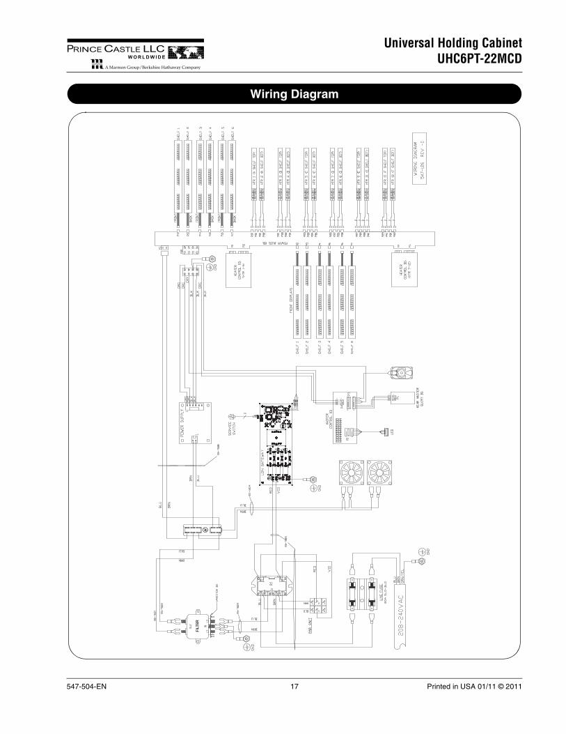
Wiring Diagram