Embed Size (px)
Citation preview
Service
Refer to Technical Sheetfor values and wiringschematics.
This manual is to be used by qualified appliance techniciansonly. Amana does not assume any responsibility for propertydamage or personal injury for improper service proceduresdone by an unqualified person.
RS5290000Revision 0April 1998
International Side by Side1997 “T” Model Refrigerators
Models and manufacturingnumbers in this manual
SR520T P1312901WSB520T P1313001W
SSD522T P1313602WSXD520T P1313701W
SBDX520T P1313202WSSD522TB P1313601WSBDT520T P1313201W
SRD520T P1313101WSRD522T P1313301WSRD526T P1313401W
SRDE520T P1312401WSBDE520T P1312301W
SRDE520TB P1312402WSRDE528T P1312601W
SRDE528TB P1312602WSRD325S5 P1313501WSRD327S3 P1312502W
SXD322 P1313901WSRDE327S3 P1312501W
SX322S2 P1313801W
Table of Contents
Important information…………………………………………………………………………. 3User Operation………………………………………………………………………………... 4Installation Instructions……………………………………………………………………….. 11Troubleshooting Chart………………………………………………………………………... 15Systems Diagnosis…………………………………………………………………………… 18Display Panel…………………………………………………………………………………. 19Display Panel Operation……………………………………………………………………... 20Electronic Functional Description………………………………………………………….. 21Component Testing………………………………………………………………………….. 34Product Design……………………………………………………………………………….. 41Service Procedures…………………………………………………………………………… 43Refrigerant Flow………………………………………………………………………………. 51Cabinet Air Flow………………………………………………………………………………. 53Water Flow…………………………………………………………………………………….. 55Typical External Sweat Pattern……………………………………………………………… 56Disassembly…………………………………………………………………………………… 57Ice Maker…………………………………………………………………………………….. 66Ice Maker Troubleshooting Chart…………………………………………………………… 71Ice Maker Wiring Diagram & Parts Layout……………………………………………….. 74
RS5290000 Rev. 0 April 1998
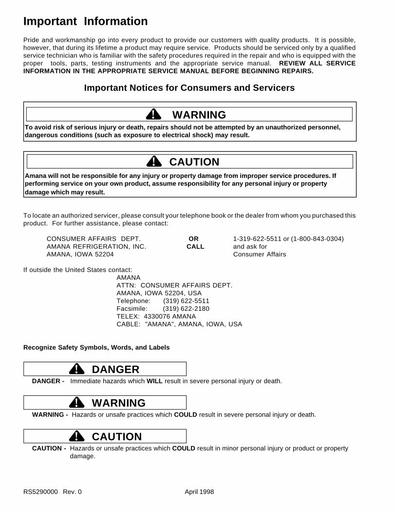
Important InformationPride and workmanship go into every product to provide our customers with quality products. It is possible,however, that during its lifetime a product may require service. Products should be serviced only by a qualifiedservice technician who is familiar with the safety procedures required in the repair and who is equipped with theproper tools, parts, testing instruments and the appropriate service manual. REVIEW ALL SERVICEINFORMATION IN THE APPROPRIATE SERVICE MANUAL BEFORE BEGINNING REPAIRS.
Important Notices for Consumers and Servicers
! WARNINGTo avoid risk of serious injury or death, repairs should not be attempted by an unauthorized personnel,dangerous conditions (such as exposure to electrical shock) may result.
Amana will not be responsible for any injury or property damage from improper service procedures. Ifperforming service on your own product, assume responsibility for any personal injury or propertydamage which may result.
To locate an authorized servicer, please consult your telephone book or the dealer from whom you purchased thisproduct. For further assistance, please contact:
CONSUMER AFFAIRS DEPT. OR 1-319-622-5511 or (1-800-843-0304)AMANA REFRIGERATION, INC. CALL and ask forAMANA, IOWA 52204 Consumer Affairs
If outside the United States contact:AMANAATTN: CONSUMER AFFAIRS DEPT.AMANA, IOWA 52204, USATelephone: (319) 622-5511Facsimile: (319) 622-2180TELEX: 4330076 AMANACABLE: "AMANA", AMANA, IOWA, USA
Recognize Safety Symbols, Words, and Labels
DANGER!DANGER - Immediate hazards which WILL result in severe personal injury or death.
WARNING!WARNING - Hazards or unsafe practices which COULD result in severe personal injury or death.
CAUTION!CAUTION - Hazards or unsafe practices which COULD result in minor personal injury or product or property
damage.
Important Information
CAUTION!
April 1998 RS5290000 Rev. 0
User Operation
Features
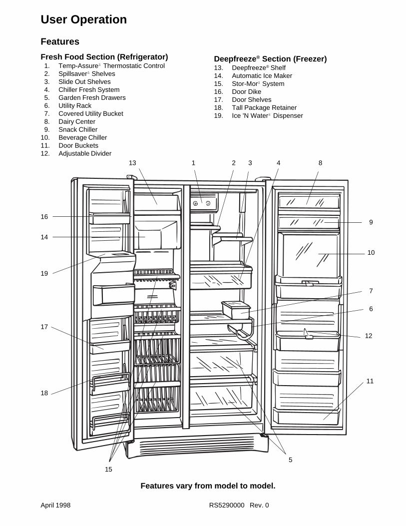
Fresh Food Section (Refrigerator) 1. Temp-Assureä Thermostatic Control 2. Spillsaverä Shelves 3. Slide Out Shelves 4. Chiller Fresh System 5. Garden Fresh Drawers 6. Utility Rack 7. Covered Utility Bucket 8. Dairy Center 9. Snack Chiller10. Beverage Chiller11. Door Buckets12. Adjustable Divider
Deepfreeze ® Section (Freezer)13. Deepfreeze® Shelf14. Automatic Ice Maker15. Stor-Morä System16. Door Dike17. Door Shelves18. Tall Package Retainer19. Ice 'N Waterä Dispenser
Features vary from model to model.
SXD20SW
1 32
18
4
5
6
7
8
9
10
11
12
13
14
15
17
16
19
RS5290000 Rev. 0 April 1998
User Operation
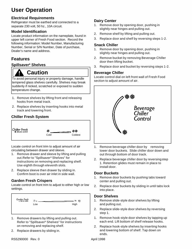
FeaturesSpillsaver ä Shelves
CautionTo avoid personal injury or property damage, handletempered glass shelves carefully. Shelves may breaksuddenly if nicked, scratched or exposed to suddentemperature change.
1. Remove shelves by lifting front and releasinghooks from metal track.
2. Replace shelves by inserting hooks into metaltrack and lowering front.
Chiller Fresh System
Garden Fresh CrispersLocate control on front trim to adjust to either high or lowsettings.
1. Remove drawers by lifting and pulling out.Refer to "Spillsaverä Shelves" for instructionson removing and replacing shelf.
2. Replace drawers by sliding in.
Locate control on front trim to adjust amount of aircirculating between drawer and sleeve.1. Remove drawer and sleeve by lifting and pulling
out.Refer to "Spillsaverä Shelves" forinstructions on removing and replacing shelf.Use eighth through eleventh slots.
2. Replace sleeve then drawer by sliding in.Confirm boot is over air inlet in side wall.
Beverage ChillerLocate control dial on left front wall of Fresh Foodsection to adjust amount of air.
1. Remove beverage chiller door by removinglower door buckets. Slide chiller door down andout through bottom of door track.
2. Replace beverage chiller door by reversingstep1. Retention glides must remain in place toinstall door.
Door Buckets1. Remove door buckets by pushing tabs toward
center and pulling out.
2. Replace door buckets by sliding in until tabs lockinto place.
Door Shelves1. Remove slide-style door shelves by lifting
and pulling out.
2. Replace slide-style door shelves by reversingstep 1.
1. Remove hook-style door shelves by tapping upeach end. Lift bottom of shelf release hooks.
2. Replace hook-style shelves by inserting hooksand lowering bottom of shelf. Tap down onends.
Dairy Center1. Remove door by opening door, pushing in
slightly near hinges and pulling out.
2. Remove shelf by lifting and pulling out.
3. Replace door and shelf by reversing steps 1-2.
Snack Chiller1. Remove door by opening door, pushing in
slightly near hinges and pulling out.
2. Remove bucket by removing Beverage Chillerdoor then lifting bucket.
3. Replace door and bucket by reversing steps 1-2.
Electrical RequirementsRefrigerator must be earthed and connected to aseparate 230 volt, 50 hz., 10A circuit.
Model IdentificationLocate product information on the nameplate, found inupper left corner of Fresh Food section. Record thefollowing information: Model Number, ManufacturingNumber, Serial or S/N Number, Date of purchase,Dealer’s name and address.
Cold Coldest
Low High
April 1998 RS5290000 Rev. 0
User OperationStor-Mor ä System1. Remove shelves and baskets by lifting and
pulling out.
2. Replace shelves and baskets by reversingstep 1.
Door Dike1. Remove door dike by pulling forward and
snapping out.
2. Replace door dike by aligning clips with holes onDeepfreeze® door. Push until dike locks in place.
Setting Controls
This refrigerator operates most efficiently in normalhousehold temperatures of 12° to 43°C.
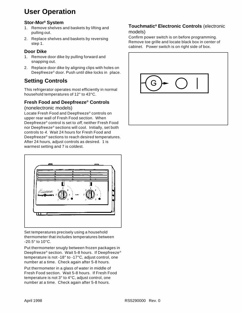
Fresh Food and Deepfreeze ® Controls(nonelectronic models)Locate Fresh Food and Deepfreeze® controls onupper rear wall of Fresh Food section. WhenDeepfreeze® control is set to off, neither Fresh Foodnor Deepfreeze® sections will cool. Initially, set bothcontrols to 4. Wait 24 hours for Fresh Food andDeepfreeze® sections to reach desired temperatures.After 24 hours, adjust controls as desired. 1 iswarmest setting and 7 is coldest.
Set temperatures precisely using a householdthermometer that includes temperatures between-20.5° to 10°C.
Put thermometer snugly between frozen packages inDeepfreeze® section. Wait 5-8 hours. If Deepfreeze®
temperature is not -18° to -17°C, adjust control, onenumber at a time. Check again after 5-8 hours.
Put thermometer in a glass of water in middle ofFresh Food section. Wait 5-8 hours. If Fresh Foodtemperature is not 3° to 4°C, adjust control, onenumber at a time. Check again after 5-8 hours.
Touchmatic ä Electronic Controls (electronicmodels)Confirm power switch is on before programming.Remove toe grille and locate black box in center ofcabinet. Power switch is on right side of box.
G
RS5290000 Rev. 0 April 1998
User Operation
Deepfreezeâ Temp
Vacation
Max Cool
Fast Freeze
Alarm Off
Display Off
Colder
Fresh Food Temp
Warmer
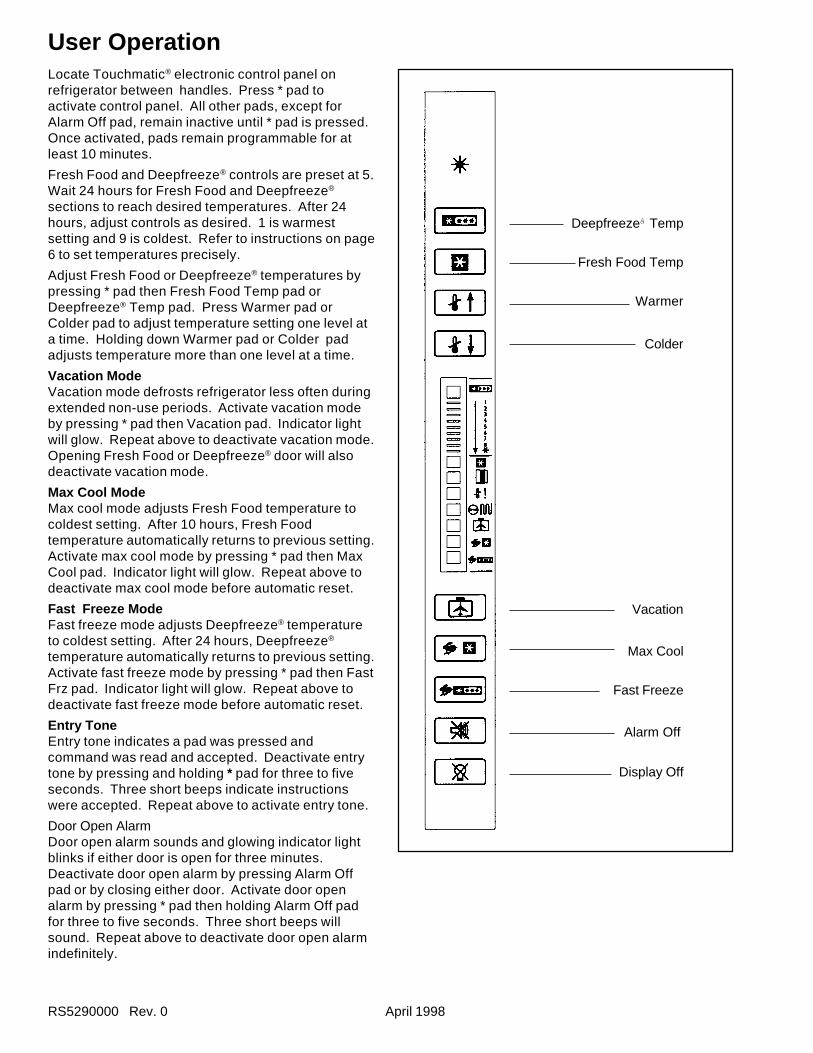
Locate Touchmatic® electronic control panel onrefrigerator between handles. Press * pad toactivate control panel. All other pads, except forAlarm Off pad, remain inactive until * pad is pressed.Once activated, pads remain programmable for atleast 10 minutes.
Fresh Food and Deepfreeze® controls are preset at 5.Wait 24 hours for Fresh Food and Deepfreeze®
sections to reach desired temperatures. After 24hours, adjust controls as desired. 1 is warmestsetting and 9 is coldest. Refer to instructions on page6 to set temperatures precisely.
Adjust Fresh Food or Deepfreeze® temperatures bypressing * pad then Fresh Food Temp pad orDeepfreeze® Temp pad. Press Warmer pad orColder pad to adjust temperature setting one level ata time. Holding down Warmer pad or Colder padadjusts temperature more than one level at a time.
Vacation ModeVacation mode defrosts refrigerator less often duringextended non-use periods. Activate vacation modeby pressing * pad then Vacation pad. Indicator lightwill glow. Repeat above to deactivate vacation mode.Opening Fresh Food or Deepfreeze® door will alsodeactivate vacation mode.
Max Cool ModeMax cool mode adjusts Fresh Food temperature tocoldest setting. After 10 hours, Fresh Foodtemperature automatically returns to previous setting.Activate max cool mode by pressing * pad then MaxCool pad. Indicator light will glow. Repeat above todeactivate max cool mode before automatic reset.
Fast Freeze ModeFast freeze mode adjusts Deepfreeze® temperatureto coldest setting. After 24 hours, Deepfreeze®
temperature automatically returns to previous setting.Activate fast freeze mode by pressing * pad then FastFrz pad. Indicator light will glow. Repeat above todeactivate fast freeze mode before automatic reset.
Entry ToneEntry tone indicates a pad was pressed andcommand was read and accepted. Deactivate entrytone by pressing and holding * pad for three to fiveseconds. Three short beeps indicate instructionswere accepted. Repeat above to activate entry tone.
Door Open AlarmDoor open alarm sounds and glowing indicator lightblinks if either door is open for three minutes.Deactivate door open alarm by pressing Alarm Offpad or by closing either door. Activate door openalarm by pressing * pad then holding Alarm Off padfor three to five seconds. Three short beeps willsound. Repeat above to deactivate door open alarmindefinitely.
April 1998 RS5290000 Rev. 0
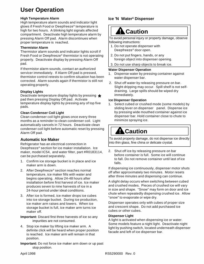
User OperationHigh Temperature AlarmHigh temperature alarm sounds and indicator lightglows if Fresh Food or Deepfreeze® temperature ishigh for two hours. A blinking light signals affectedcompartment. Deactivate high temperature alarm bypressing Alarm Off pad. Alarm discontinues whenproper temperature is reached.
Thermistor AlarmThermistor alarm sounds and indicator lights scroll ifFresh Food or Deepfreeze® thermistor is not operatingproperly. Deactivate display by pressing Alarm Offpad.
If thermistor alarm sounds, contact an authorizedservicer immediately. If Alarm Off pad is pressed,thermistor control retests to confirm situation has beencorrected. Alarm sounds again if thermistor is still notoperating properly.
Display LightsDeactivate temperature display lights by pressing *pad then pressing Display Off pad. Activatetemperature display lights by pressing any of top fivepads.
Clean Condenser Coil LightClean condenser coil light glows once every threemonths as a reminder to clean condenser coil. Lightautomatically cancels in 72 hours. Deactivate cleancondenser coil light before automatic reset by pressingAlarm Off pad.
Automatic Ice MakerRefrigerator has an electrical connection inDeepfreeze® section for ice maker installation. Icemaker, model IC54, and water filter, part #R0183114,can be purchased separately.
1. Confirm ice storage bucket is in place and icemaker arm is down.
2. After Deepfreeze® section reaches normaltemperature, ice maker fills with water andbegins operating. Allow 24-48 hours afterinstallation before first harvest of ice. Ice makerproduces seven to nine harvests of ice in a24-hour period under ideal conditions.
3. After ice is formed, ice maker drops ice cubesinto ice storage bucket. During ice production,ice maker arm raises and lowers. When icestorage bucket is full, ice maker arm turns icemaker off.
Important: Discard first three harvests of ice so anyimpurities are not consumed.
4. Stop ice maker by lifting ice maker arm. Adefinite click will be heard when proper positionis reached. Ice maker arm will remain in thatposition.
Important: Do not force ice maker arm down or up paststop position.
Ice 'N Water ä Dispenser
CautionTo avoid personal injury or property damage, observefollowing instructions:1. Do not operate dispenser with
Deepfreeze® door open.
2. Do not put fingers, hands, or anyforeign object into dispenser opening.
3. Do not use sharp objects to break ice.
Water Dispenser Operation1. Dispense water by pressing container against
water dispenser bar.
2. Shut off water by releasing pressure on bar.Slight dripping may occur. Spill shelf is not self-draining. Large spills should be wiped dryimmediately.
Ice Dispenser Operation1. Select cubed or crushed mode (some models) by
sliding lever on dispenser panel. Dispense iceby pressing wide mouthed container against icedispenser bar. Hold container close to chute tominimize spraying ice.
CautionTo avoid property damage, do not dispense ice directlyinto thin glass, fine china or delicate crystal.
2. Shut off ice by releasing pressure on barbefore container is full. Some ice will continueto fall. Do not remove container until last of icefalls.
If dispensing ice continuously, dispenser motor shutsoff after approximately two minutes. Motor resetsafter three minutes and dispensing can continue.
A slight delay occurs when switching between cubedand crushed modes. Pieces of crushed ice will varyin size and shape. “Snow” may form on door and icechute when repeatedly dispensing crushed ice. Allow“snow” to evaporate or wipe dry.
Dispenser operates only with cubes of proper sizeand crescent shape. Do not add purchased icecubes or other cubes.
Dispenser LightA light is activated when dispensing ice or water.Some models feature a night light. Deactivate nightlight by pushing switch, located underneath dispenserfacade and left of ice dispenser bar.
RS5290000 Rev. 0 April 1998
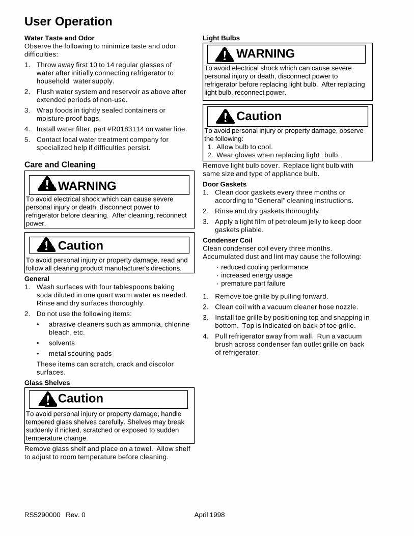
User OperationWater Taste and OdorObserve the following to minimize taste and odordifficulties:
1. Throw away first 10 to 14 regular glasses ofwater after initially connecting refrigerator tohousehold water supply.
2. Flush water system and reservoir as above afterextended periods of non-use.
3. Wrap foods in tightly sealed containers ormoisture proof bags.
4. Install water filter, part #R0183114 on water line.
5. Contact local water treatment company forspecialized help if difficulties persist.
Care and Cleaning
WARNINGTo avoid electrical shock which can cause severepersonal injury or death, disconnect power torefrigerator before cleaning. After cleaning, reconnectpower.
CautionTo avoid personal injury or property damage, read andfollow all cleaning product manufacturer's directions.
General1. Wash surfaces with four tablespoons baking
soda diluted in one quart warm water as needed.Rinse and dry surfaces thoroughly.
2. Do not use the following items:
• abrasive cleaners such as ammonia, chlorinebleach, etc.
• solvents
• metal scouring pads
These items can scratch, crack and discolorsurfaces.
Glass Shelves
CautionTo avoid personal injury or property damage, handletempered glass shelves carefully. Shelves may breaksuddenly if nicked, scratched or exposed to suddentemperature change.
Remove glass shelf and place on a towel. Allow shelfto adjust to room temperature before cleaning.
Light Bulbs
WARNINGTo avoid electrical shock which can cause severepersonal injury or death, disconnect power torefrigerator before replacing light bulb. After replacinglight bulb, reconnect power.
CautionTo avoid personal injury or property damage, observethe following:1. Allow bulb to cool.2. Wear gloves when replacing light bulb.
Remove light bulb cover. Replace light bulb withsame size and type of appliance bulb.
Door Gaskets1. Clean door gaskets every three months or
according to "General" cleaning instructions.
2. Rinse and dry gaskets thoroughly.
3. Apply a light film of petroleum jelly to keep doorgaskets pliable.
Condenser CoilClean condenser coil every three months.Accumulated dust and lint may cause the following:
· reduced cooling performance · increased energy usage · premature part failure
1. Remove toe grille by pulling forward.
2. Clean coil with a vacuum cleaner hose nozzle.
3. Install toe grille by positioning top and snapping inbottom. Top is indicated on back of toe grille.
4. Pull refrigerator away from wall. Run a vacuumbrush across condenser fan outlet grille on backof refrigerator.
April 1998 RS5290000 Rev. 0
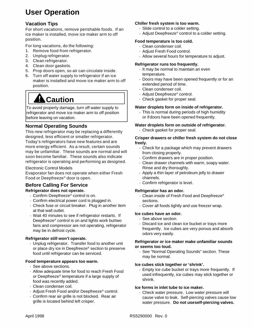
User OperationVacation TipsFor short vacations, remove perishable foods. If anice maker is installed, move ice maker arm to offposition.
For long vacations, do the following:1. Remove food from refrigerator.2. Unplug refrigerator.3. Clean refrigerator.4. Clean door gaskets.5. Prop doors open, so air can circulate inside.6. Turn off water supply to refrigerator if an ice
maker is installed and move ice maker arm to offposition.
CautionTo avoid property damage, turn off water supply torefrigerator and move ice maker arm to off positionbefore leaving on vacation.
Normal Operating SoundsThis new refrigerator may be replacing a differentlydesigned, less efficient or smaller refrigerator.Today’s refrigerators have new features and aremore energy efficient. As a result, certain soundsmay be unfamiliar. These sounds are normal and willsoon become familiar. These sounds also indicaterefrigerator is operating and performing as designed.
Electronic Control ModelsEvaporator fan does not operate when either FreshFood or Deepfreeze® door is open.
Before Calling For ServiceRefrigerator does not operate.
· Confirm Deepfreeze® control is on.· Confirm electrical power cord is plugged in.· Check fuse or circuit breaker. Plug in another item
at that wall outlet.· Wait 40 minutes to see if refrigerator restarts. If
Deepfreeze® control is on and lights work buttwofans and compressor are not operating, refrigeratormay be in defrost cycle.
Refrigerator still won’t operate.· Unplug refrigerator. Transfer food to another unit
or place dry ice in Deepfreeze® section to preservefood until refrigerator can be serviced.
Food temperature appears too warm.· See above sections.· Allow adequate time for food to reach Fresh Food
or Deepfreeze® temperature if a large supply offood was recently added.
· Clean condenser coil.· Adjust Fresh Food and/or Deepfreeze® control.· Confirm rear air grille is not blocked. Rear air
grille is located behind left crisper.
Chiller fresh system is too warm.· Slide control to a colder setting.· Adjust Deepfreeze® control to a colder setting.
Food temperature is too cold.· Clean condenser coil.· Adjust Fresh Food control.· Allow several hours for temperature to adjust.
Refrigerator runs too frequently.· It may be normal to maintain an even
temperature.· Doors may have been opened frequently or for an
extended period of time.· Clean condenser coil.· Adjust Deepfreeze® control.· Check gasket for proper seal.
Water droplets form on inside of refrigerator.· This is normal during periods of high humidity
or if doors have been opened frequently.
Water droplets form on outside of refrigerator.· Check gasket for proper seal.
Crisper drawers or chiller fresh system do not closefreely.
· Check for a package which may prevent drawersfrom closing properly.
· Confirm drawers are in proper position.· Clean drawer channels with warm, soapy water.
Rinse and dry thoroughly.· Apply a thin layer of petroleum jelly to drawer
channels.· Confirm refrigerator is level.
Refrigerator has an odor.· Clean inside of Fresh Food and Deepfreeze®
sections.· Cover all foods tightly and use freezer wrap.
Ice cubes have an odor.· See above section.· Discard ice and clean ice bucket or trays more
frequently. Ice cubes are very porous and absorbodors very easily.
Refrigerator or ice maker make unfamiliar soundsor seems too loud.
· See "Normal Operating Sounds" section. Thesemay be normal.
Ice cubes stick together or ‘shrink’.· Empty ice cube bucket or trays more frequently. If
used infrequently, ice cubes may stick together orshrink.
Ice forms in inlet tube to ice maker.· Check water pressure. Low water pressure will
cause valve to leak. Self-piercing valves cause lowwater pressure. Do not useself-piercing valves.
RS5290000 Rev. 0 February 1998
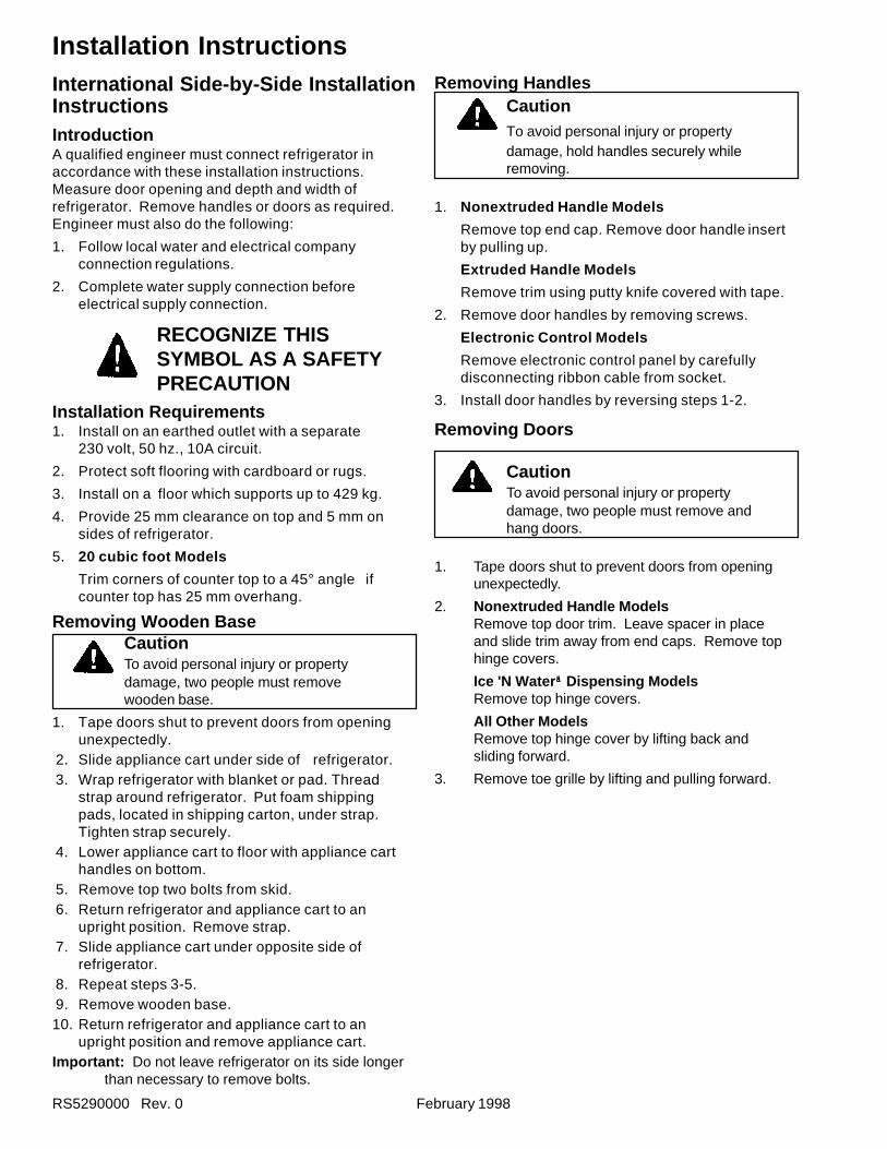
Installation Instructions
IntroductionA qualified engineer must connect refrigerator inaccordance with these installation instructions.Measure door opening and depth and width ofrefrigerator. Remove handles or doors as required.Engineer must also do the following:
1. Follow local water and electrical companyconnection regulations.
2. Complete water supply connection beforeelectrical supply connection.
RECOGNIZE THISSYMBOL AS A SAFETYPRECAUTION
Installation Requirements1. Install on an earthed outlet with a separate
230 volt, 50 hz., 10A circuit.
2. Protect soft flooring with cardboard or rugs.
3. Install on a floor which supports up to 429 kg.
4. Provide 25 mm clearance on top and 5 mm onsides of refrigerator.
5. 20 cubic foot Models
Trim corners of counter top to a 45° angle ifcounter top has 25 mm overhang.
Removing Wooden BaseCautionTo avoid personal injury or propertydamage, two people must removewooden base.
1. Tape doors shut to prevent doors from openingunexpectedly.
2. Slide appliance cart under side of refrigerator. 3. Wrap refrigerator with blanket or pad. Thread
strap around refrigerator. Put foam shippingpads, located in shipping carton, under strap.Tighten strap securely.
4. Lower appliance cart to floor with appliance carthandles on bottom.
5. Remove top two bolts from skid. 6. Return refrigerator and appliance cart to an
upright position. Remove strap. 7. Slide appliance cart under opposite side of
refrigerator. 8. Repeat steps 3-5. 9. Remove wooden base.10. Return refrigerator and appliance cart to an
upright position and remove appliance cart.Important: Do not leave refrigerator on its side longer
than necessary to remove bolts.
International Side-by-Side InstallationInstructions
Removing HandlesCautionTo avoid personal injury or propertydamage, hold handles securely whileremoving.
1. Nonextruded Handle Models
Remove top end cap. Remove door handle insertby pulling up.
Extruded Handle Models
Remove trim using putty knife covered with tape.
2. Remove door handles by removing screws.
Electronic Control Models
Remove electronic control panel by carefullydisconnecting ribbon cable from socket.
3. Install door handles by reversing steps 1-2.
Removing Doors
CautionTo avoid personal injury or propertydamage, two people must remove andhang doors.
1. Tape doors shut to prevent doors from openingunexpectedly.
2. Nonextruded Handle ModelsRemove top door trim. Leave spacer in placeand slide trim away from end caps. Remove tophinge covers.
Ice 'N Water äääää Dispensing ModelsRemove top hinge covers.
All Other ModelsRemove top hinge cover by lifting back andsliding forward.
3. Remove toe grille by lifting and pulling forward.
February 1998 RS5290000 Rev. 0
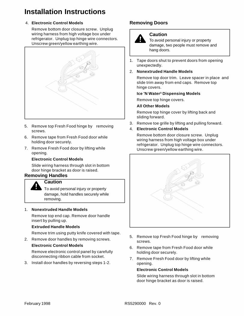
Installation Instructions 4. Electronic Control Models
Remove bottom door closure screw. Unplugwiring harness from high voltage box underrefrigerator. Unplug top hinge wire connectors.Unscrew green/yellow earthing wire.
5. Remove top Fresh Food hinge by removingscrews.
6. Remove tape from Fresh Food door whileholding door securely.
7. Remove Fresh Food door by lifting whileopening.
Electronic Control Models
Slide wiring harness through slot in bottomdoor hinge bracket as door is raised.
Removing HandlesCautionTo avoid personal injury or propertydamage, hold handles securely whileremoving.
1. Nonextruded Handle Models
Remove top end cap. Remove door handleinsert by pulling up.
Extruded Handle Models
Remove trim using putty knife covered with tape.
2. Remove door handles by removing screws.
Electronic Control Models
Remove electronic control panel by carefullydisconnecting ribbon cable from socket.
3. Install door handles by reversing steps 1-2.
Removing Doors
CautionTo avoid personal injury or propertydamage, two people must remove andhang doors.
1. Tape doors shut to prevent doors from openingunexpectedly.
2. Nonextruded Handle Models
Remove top door trim. Leave spacer in place andslide trim away from end caps. Remove tophinge covers.
Ice 'N Water ä Dispensing Models
Remove top hinge covers.
All Other Models
Remove top hinge cover by lifting back andsliding forward.
3. Remove toe grille by lifting and pulling forward.4. Electronic Control Models
Remove bottom door closure screw. Unplugwiring harness from high voltage box underrefrigerator. Unplug top hinge wire connectors.Unscrew green/yellow earthing wire.
5. Remove top Fresh Food hinge by removingscrews.
6. Remove tape from Fresh Food door whileholding door securely.
7. Remove Fresh Food door by lifting whileopening.
Electronic Control Models
Slide wiring harness through slot in bottomdoor hinge bracket as door is raised.
RS5290000 Rev. 0 February 1998
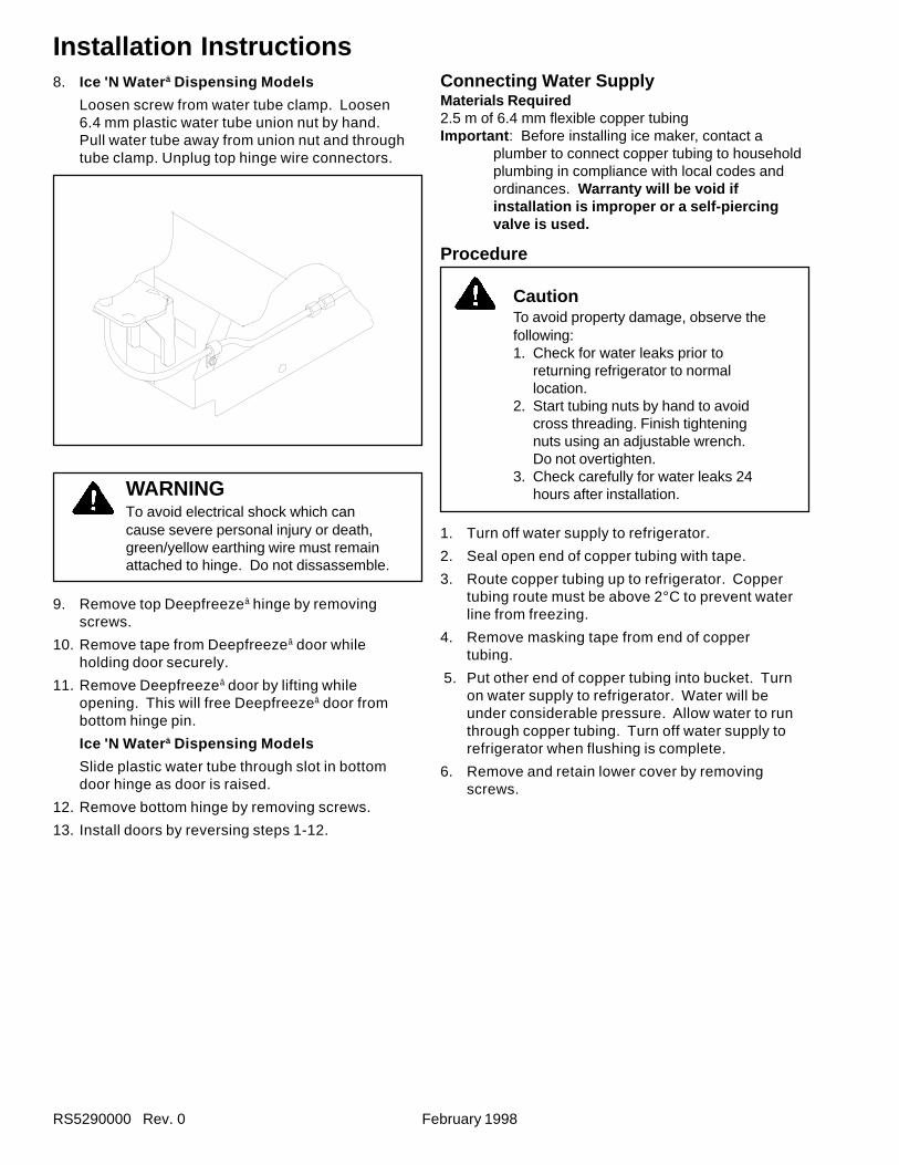
Installation Instructions8. Ice 'N Water ä Dispensing Models
Loosen screw from water tube clamp. Loosen6.4 mm plastic water tube union nut by hand.Pull water tube away from union nut and throughtube clamp. Unplug top hinge wire connectors.
Connecting Water SupplyMaterials Required2.5 m of 6.4 mm flexible copper tubingImportant : Before installing ice maker, contact a
plumber to connect copper tubing to householdplumbing in compliance with local codes andordinances. Warranty will be void ifinstallation is improper or a self-piercingvalve is used.
Procedure
CautionTo avoid property damage, observe thefollowing:1. Check for water leaks prior to
returning refrigerator to normallocation.
2. Start tubing nuts by hand to avoidcross threading. Finish tighteningnuts using an adjustable wrench.Do not overtighten.
3. Check carefully for water leaks 24hours after installation.
1. Turn off water supply to refrigerator.
2. Seal open end of copper tubing with tape.
3. Route copper tubing up to refrigerator. Coppertubing route must be above 2°C to prevent waterline from freezing.
4. Remove masking tape from end of coppertubing.
5. Put other end of copper tubing into bucket. Turnon water supply to refrigerator. Water will beunder considerable pressure. Allow water to runthrough copper tubing. Turn off water supply torefrigerator when flushing is complete.
6. Remove and retain lower cover by removingscrews.
WARNINGTo avoid electrical shock which cancause severe personal injury or death,green/yellow earthing wire must remainattached to hinge. Do not dissassemble.
9. Remove top Deepfreezeâ hinge by removingscrews.
10. Remove tape from Deepfreezeâ door whileholding door securely.
11. Remove Deepfreezeâ door by lifting whileopening. This will free Deepfreezeâ door frombottom hinge pin.
Ice 'N Water ä Dispensing Models
Slide plastic water tube through slot in bottomdoor hinge as door is raised.
12. Remove bottom hinge by removing screws.
13. Install doors by reversing steps 1-12.
February 1998 RS5290000 Rev. 0
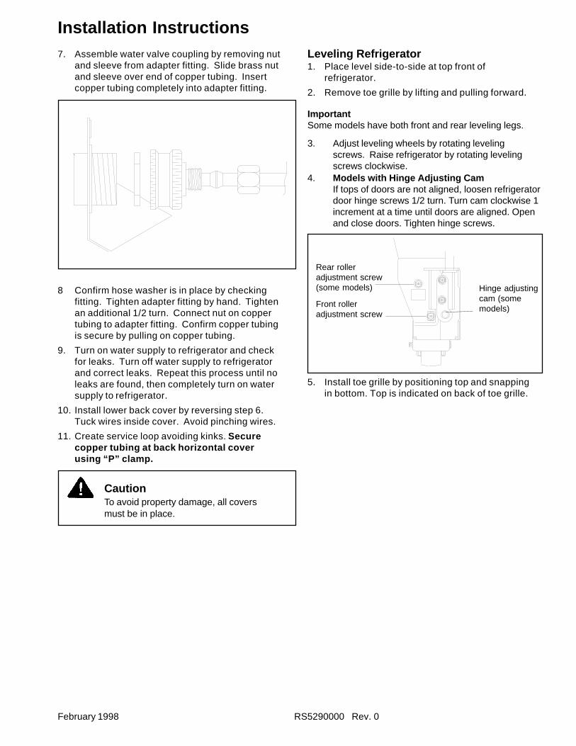
Installation Instructions7. Assemble water valve coupling by removing nut
and sleeve from adapter fitting. Slide brass nutand sleeve over end of copper tubing. Insertcopper tubing completely into adapter fitting.
Leveling Refrigerator1. Place level side-to-side at top front of
refrigerator.
2. Remove toe grille by lifting and pulling forward.
ImportantSome models have both front and rear leveling legs.
3. Adjust leveling wheels by rotating levelingscrews. Raise refrigerator by rotating levelingscrews clockwise.
8 Confirm hose washer is in place by checkingfitting. Tighten adapter fitting by hand. Tightenan additional 1/2 turn. Connect nut on coppertubing to adapter fitting. Confirm copper tubingis secure by pulling on copper tubing.
9. Turn on water supply to refrigerator and checkfor leaks. Turn off water supply to refrigeratorand correct leaks. Repeat this process until noleaks are found, then completely turn on watersupply to refrigerator.
10. Install lower back cover by reversing step 6.Tuck wires inside cover. Avoid pinching wires.
11. Create service loop avoiding kinks. Securecopper tubing at back horizontal coverusing “P” clamp.
CautionTo avoid property damage, all coversmust be in place.
4. Models with Hinge Adjusting CamIf tops of doors are not aligned, loosen refrigeratordoor hinge screws 1/2 turn. Turn cam clockwise 1increment at a time until doors are aligned. Openand close doors. Tighten hinge screws.
Front rolleradjustment screw
5. Install toe grille by positioning top and snappingin bottom. Top is indicated on back of toe grille.
Rear rolleradjustment screw(some models) Hinge adjusting
cam (somemodels)
RS5290000 Rev. 0 April 1998
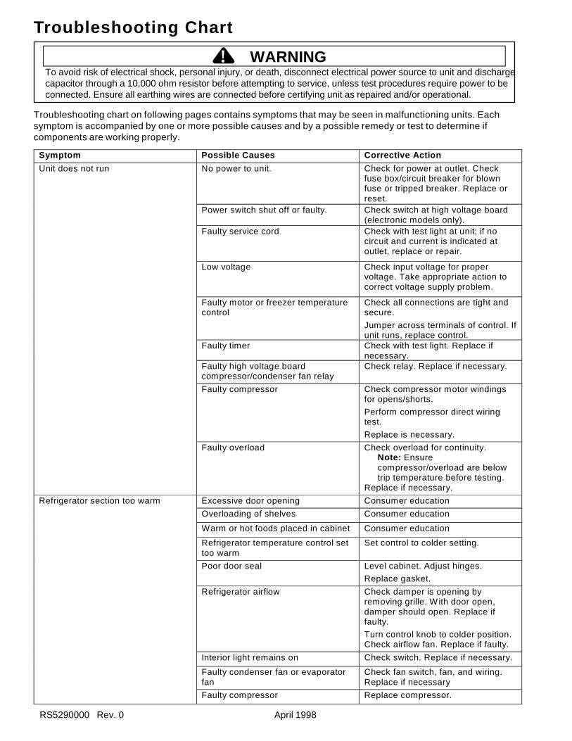
Troubleshooting Chart
Symptom Possible Causes Corrective Action
No power to unit. Check for power at outlet. Checkfuse box/circuit breaker for blownfuse or tripped breaker. Replace orreset.
Power switch shut off or faulty. Check switch at high voltage board(electronic models only).
Faulty service cord Check with test light at unit; if nocircuit and current is indicated atoutlet, replace or repair.
Low voltage Check input voltage for propervoltage. Take appropriate action tocorrect voltage supply problem.
Faulty motor or freezer temperaturecontrol
Check all connections are tight andsecure.
Jumper across terminals of control. Ifunit runs, replace control.
Faulty timer Check with test light. Replace ifnecessary.
Faulty high voltage boardcompressor/condenser fan relay
Check relay. Replace if necessary.
Faulty compressor Check compressor motor windingsfor opens/shorts.
Perform compressor direct wiringtest.
Replace is necessary.
Unit does not run
Faulty overload Check overload for continuity.Note: Ensurecompressor/overload are belowtrip temperature before testing.
Replace if necessary.
Excessive door opening Consumer education
Overloading of shelves Consumer education
Warm or hot foods placed in cabinet Consumer education
Refrigerator temperature control settoo warm
Set control to colder setting.
Poor door seal Level cabinet. Adjust hinges.
Replace gasket.
Refrigerator airflow Check damper is opening byremoving grille. With door open,damper should open. Replace iffaulty.
Turn control knob to colder position.Check airflow fan. Replace if faulty.
Interior light remains on Check switch. Replace if necessary.
Faulty condenser fan or evaporatorfan
Check fan switch, fan, and wiring.Replace if necessary
Refrigerator section too warm
Faulty compressor Replace compressor.
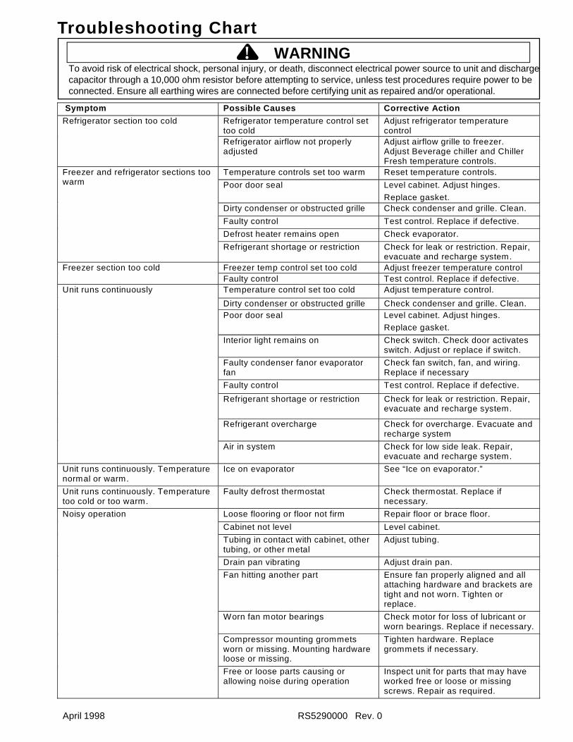
Troubleshooting chart on following pages contains symptoms that may be seen in malfunctioning units. Eachsymptom is accompanied by one or more possible causes and by a possible remedy or test to determine ifcomponents are working properly.
To avoid risk of electrical shock, personal injury, or death, disconnect electrical power source to unit and dischargecapacitor through a 10,000 ohm resistor before attempting to service, unless test procedures require power to beconnected. Ensure all earthing wires are connected before certifying unit as repaired and/or operational.
! WARNING
April 1998 RS5290000 Rev. 0
Symptom Possible Causes Corrective Action
Refrigerator temperature control settoo cold
Adjust refrigerator temperaturecontrol
Refrigerator section too cold
Refrigerator airflow not properlyadjusted
Adjust airflow grille to freezer.Adjust Beverage chiller and ChillerFresh temperature controls.
Temperature controls set too warm Reset temperature controls.
Poor door seal Level cabinet. Adjust hinges.
Replace gasket.Dirty condenser or obstructed grille Check condenser and grille. Clean.
Faulty control Test control. Replace if defective.
Defrost heater remains open Check evaporator.
Freezer and refrigerator sections toowarm
Refrigerant shortage or restriction Check for leak or restriction. Repair,evacuate and recharge system.
Freezer temp control set too cold Adjust freezer temperature controlFreezer section too coldFaulty control Test control. Replace if defective.Temperature control set too cold Adjust temperature control.
Dirty condenser or obstructed grille Check condenser and grille. Clean.Poor door seal Level cabinet. Adjust hinges.
Replace gasket.
Interior light remains on Check switch. Check door activatesswitch. Adjust or replace if switch.
Faulty condenser fanor evaporatorfan
Check fan switch, fan, and wiring.Replace if necessary
Faulty control Test control. Replace if defective.
Refrigerant shortage or restriction Check for leak or restriction. Repair,evacuate and recharge system.
Refrigerant overcharge Check for overcharge. Evacuate andrecharge system
Unit runs continuously
Air in system Check for low side leak. Repair,evacuate and recharge system.
Unit runs continuously. Temperaturenormal or warm.
Ice on evaporator See “Ice on evaporator.”
Unit runs continuously. Temperaturetoo cold or too warm.
Faulty defrost thermostat Check thermostat. Replace ifnecessary.
Loose flooring or floor not firm Repair floor or brace floor.
Cabinet not level Level cabinet.
Tubing in contact with cabinet, othertubing, or other metal
Adjust tubing.
Drain pan vibrating Adjust drain pan.
Fan hitting another part Ensure fan properly aligned and allattaching hardware and brackets aretight and not worn. Tighten orreplace.
Worn fan motor bearings Check motor for loss of lubricant orworn bearings. Replace if necessary.
Compressor mounting grommetsworn or missing. Mounting hardwareloose or missing.
Tighten hardware. Replacegrommets if necessary.
Noisy operation
Free or loose parts causing orallowing noise during operation
Inspect unit for parts that may haveworked free or loose or missingscrews. Repair as required.
Troubleshooting Chart
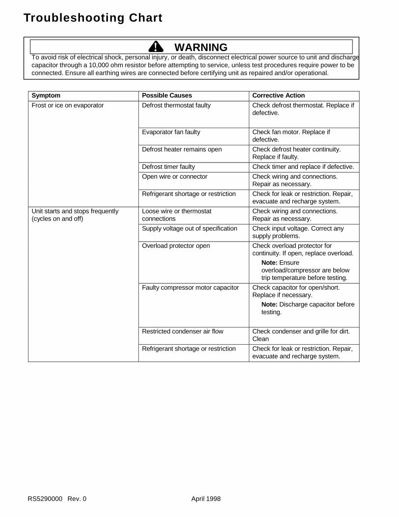
To avoid risk of electrical shock, personal injury, or death, disconnect electrical power source to unit and dischargecapacitor through a 10,000 ohm resistor before attempting to service, unless test procedures require power to beconnected. Ensure all earthing wires are connected before certifying unit as repaired and/or operational.
! WARNING
RS5290000 Rev. 0 April 1998
Symptom Possible Causes Corrective Action
Defrost thermostat faulty Check defrost thermostat. Replace ifdefective.
Evaporator fan faulty Check fan motor. Replace ifdefective.
Defrost heater remains open Check defrost heater continuity.Replace if faulty.
Defrost timer faulty Check timer and replace if defective.
Open wire or connector Check wiring and connections.Repair as necessary.
Frost or ice on evaporator
Refrigerant shortage or restriction Check for leak or restriction. Repair,evacuate and recharge system.
Loose wire or thermostatconnections
Check wiring and connections.Repair as necessary.
Supply voltage out of specification Check input voltage. Correct anysupply problems.
Overload protector open Check overload protector forcontinuity. If open, replace overload.
Note: Ensureoverload/compressor are belowtrip temperature before testing.
Faulty compressor motor capacitor Check capacitor for open/short.Replace if necessary.
Note: Discharge capacitor beforetesting.
Restricted condenser air flow Check condenser and grille for dirt.Clean
Unit starts and stops frequently(cycles on and off)
Refrigerant shortage or restriction Check for leak or restriction. Repair,evacuate and recharge system.
Troubleshooting Chart
To avoid risk of electrical shock, personal injury, or death, disconnect electrical power source to unit and dischargecapacitor through a 10,000 ohm resistor before attempting to service, unless test procedures require power to beconnected. Ensure all earthing wires are connected before certifying unit as repaired and/or operational.
! WARNING
April 1998 RS5290000 Rev. 0
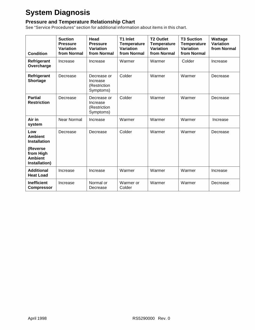
System DiagnosisPressure and Temperature Relationship ChartSee “Service Procedures” section for additional information about items in this chart.
Condition
SuctionPressureVariationfrom Normal
HeadPressureVariationfrom Normal
T1 InletTemperatureVariationfrom Normal
T2 OutletTemperatureVariationfrom Normal
T3 SuctionTemperatureVariationfrom Normal
WattageVariationfrom Normal
RefrigerantOvercharge
Increase Increase Warmer Warmer Colder Increase
RefrigerantShortage
Decrease Decrease orIncrease(RestrictionSymptoms)
Colder Warmer Warmer Decrease
PartialRestriction
Decrease Decrease orIncrease(RestrictionSymptoms)
Colder Warmer Warmer Decrease
Air insystem
Near Normal Increase Warmer Warmer Warmer Increase
LowAmbientInstallation
(Reversefrom HighAmbientInstallation)
Decrease Decrease Colder Warmer Warmer Decrease
AdditionalHeat Load
Increase Increase Warmer Warmer Warmer Increase
InefficientCompressor
Increase Normal orDecrease
Warmer orColder
Warmer Warmer Decrease
RS5290000 Rev. 0 April 1998
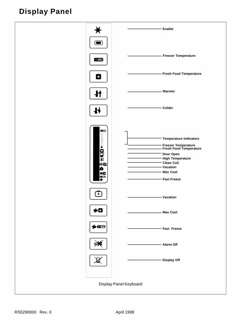
Display Panel
Display Panel Keyboard
Enable
Freezer Temperature
Fresh Food Temperature
Warmer
Colder
Freezer Temperature
Door Open
Fresh Food Temperature
Temperature Indicators
High Temperature
VacationMax Cool
Fast Freeze
Vacation
Max Cool
Fast Freeze
Alarm Off
Display Off
Clean Coil
12
34
56
78
April 1998 RS5290000 Rev. 0
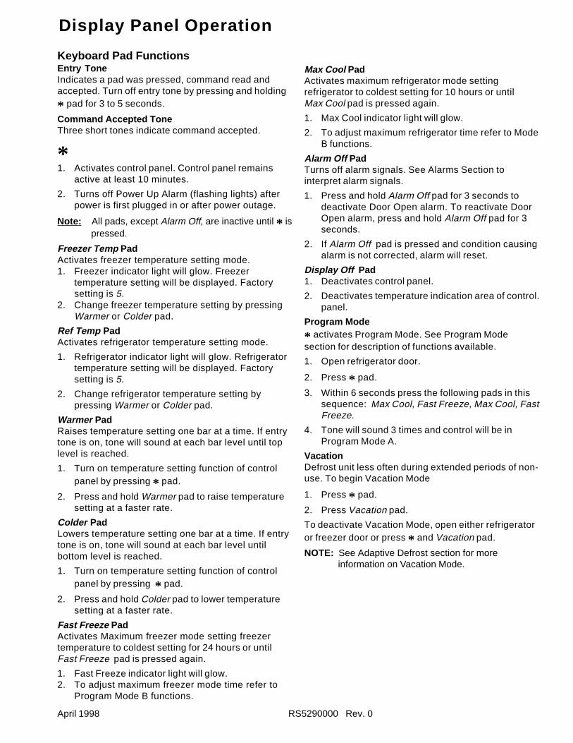
Max Cool PadActivates maximum refrigerator mode settingrefrigerator to coldest setting for 10 hours or untilMax Cool pad is pressed again.
1. Max Cool indicator light will glow.
2. To adjust maximum refrigerator time refer to ModeB functions.
Alarm Off PadTurns off alarm signals. See Alarms Section tointerpret alarm signals.
1. Press and hold Alarm Off pad for 3 seconds todeactivate Door Open alarm. To reactivate DoorOpen alarm, press and hold Alarm Off pad for 3seconds.
2. If Alarm Off pad is pressed and condition causingalarm is not corrected, alarm will reset.
Display Off Pad1. Deactivates control panel.
2. Deactivates temperature indication area of control.panel.
Program Mode
* activates Program Mode. See Program Modesection for description of functions available.
1. Open refrigerator door.
2. Press * pad.
3. Within 6 seconds press the following pads in thissequence: Max Cool, Fast Freeze, Max Cool, FastFreeze.
4. Tone will sound 3 times and control will be inProgram Mode A.
VacationDefrost unit less often during extended periods of non-use. To begin Vacation Mode
1. Press * pad.
2. Press Vacation pad.
To deactivate Vacation Mode, open either refrigeratoror freezer door or press * and Vacation pad.
NOTE: See Adaptive Defrost section for moreinformation on Vacation Mode.
Display Panel Operation
Keyboard Pad FunctionsEntry ToneIndicates a pad was pressed, command read andaccepted. Turn off entry tone by pressing and holding
* pad for 3 to 5 seconds.
Command Accepted ToneThree short tones indicate command accepted.
*1. Activates control panel. Control panel remains
active at least 10 minutes.
2. Turns off Power Up Alarm (flashing lights) afterpower is first plugged in or after power outage.
Note: All pads, except Alarm Off, are inactive until * ispressed.
Freezer Temp PadActivates freezer temperature setting mode.1. Freezer indicator light will glow. Freezer
temperature setting will be displayed. Factorysetting is 5.
2. Change freezer temperature setting by pressingWarmer or Colder pad.
Ref Temp PadActivates refrigerator temperature setting mode.
1. Refrigerator indicator light will glow. Refrigeratortemperature setting will be displayed. Factorysetting is 5.
2. Change refrigerator temperature setting bypressing Warmer or Colder pad.
Warmer PadRaises temperature setting one bar at a time. If entrytone is on, tone will sound at each bar level until toplevel is reached.
1. Turn on temperature setting function of controlpanel by pressing * pad.
2. Press and hold Warmer pad to raise temperaturesetting at a faster rate.
Colder PadLowers temperature setting one bar at a time. If entrytone is on, tone will sound at each bar level untilbottom level is reached.
1. Turn on temperature setting function of controlpanel by pressing * pad.
2. Press and hold Colder pad to lower temperaturesetting at a faster rate.
Fast Freeze PadActivates Maximum freezer mode setting freezertemperature to coldest setting for 24 hours or untilFast Freeze pad is pressed again.
1. Fast Freeze indicator light will glow.2. To adjust maximum freezer mode time refer to
Program Mode B functions.
RS5290000 Rev. 0 April 1998
Electronic Functional Description
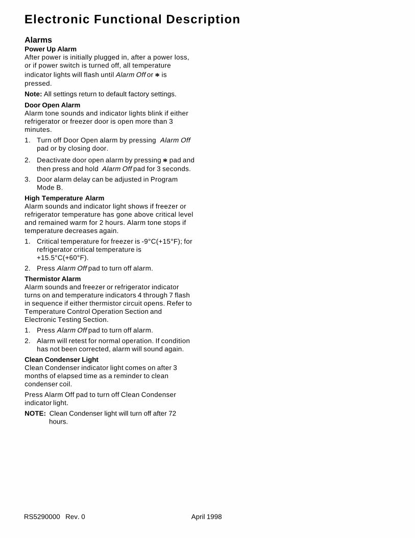
AlarmsPower Up AlarmAfter power is initially plugged in, after a power loss,or if power switch is turned off, all temperatureindicator lights will flash until Alarm Off or * ispressed.
Note: All settings return to default factory settings.
Door Open AlarmAlarm tone sounds and indicator lights blink if eitherrefrigerator or freezer door is open more than 3minutes.
1. Turn off Door Open alarm by pressing Alarm Offpad or by closing door.
2. Deactivate door open alarm by pressing * pad andthen press and hold Alarm Off pad for 3 seconds.
3. Door alarm delay can be adjusted in ProgramMode B.
High Temperature AlarmAlarm sounds and indicator light shows if freezer orrefrigerator temperature has gone above critical leveland remained warm for 2 hours. Alarm tone stops iftemperature decreases again.
1. Critical temperature for freezer is -9°C(+15°F); forrefrigerator critical temperature is+15.5°C(+60°F).
2. Press Alarm Off pad to turn off alarm.
Thermistor AlarmAlarm sounds and freezer or refrigerator indicatorturns on and temperature indicators 4 through 7 flashin sequence if either thermistor circuit opens. Refer toTemperature Control Operation Section andElectronic Testing Section.
1. Press Alarm Off pad to turn off alarm.
2. Alarm will retest for normal operation. If conditionhas not been corrected, alarm will sound again.
Clean Condenser LightClean Condenser indicator light comes on after 3months of elapsed time as a reminder to cleancondenser coil.
Press Alarm Off pad to turn off Clean Condenserindicator light.
NOTE: Clean Condenser light will turn off after 72hours.
April 1998 RS5290000 Rev. 0
Electronic Functional Description
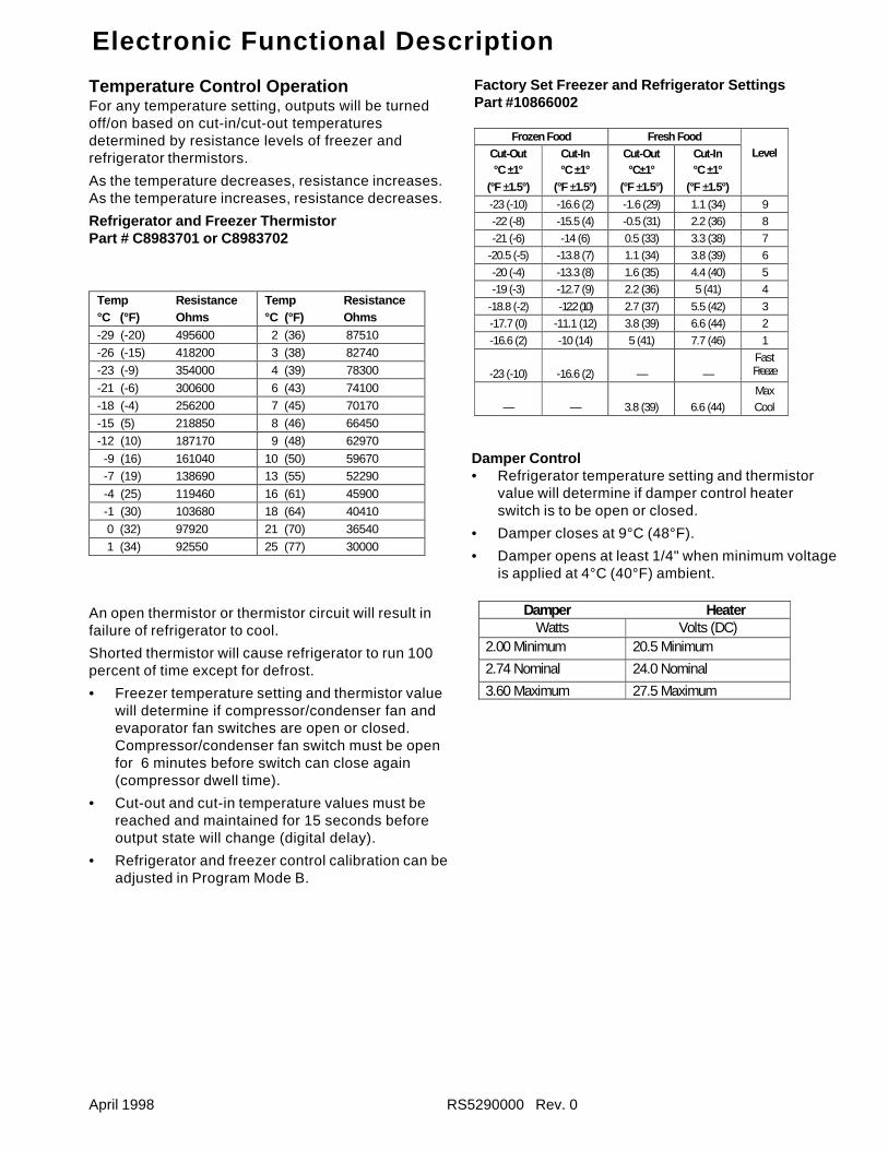
Temperature Control OperationFor any temperature setting, outputs will be turnedoff/on based on cut-in/cut-out temperaturesdetermined by resistance levels of freezer andrefrigerator thermistors.
As the temperature decreases, resistance increases.As the temperature increases, resistance decreases.
Refrigerator and Freezer ThermistorPart # C8983701 or C8983702
Temp Resistance°C (°F) Ohms
Temp Resistance°C (°F) Ohms
-29 (-20) 495600 2 (36) 87510-26 (-15) 418200 3 (38) 82740-23 (-9) 354000 4 (39) 78300
-21 (-6) 300600 6 (43) 74100-18 (-4) 256200 7 (45) 70170-15 (5) 218850 8 (46) 66450-12 (10) 187170 9 (48) 62970
-9 (16) 161040 10 (50) 59670 -7 (19) 138690 13 (55) 52290
-4 (25) 119460 16 (61) 45900 -1 (30) 103680 18 (64) 40410 0 (32) 97920 21 (70) 36540 1 (34) 92550 25 (77) 30000
An open thermistor or thermistor circuit will result infailure of refrigerator to cool.
Shorted thermistor will cause refrigerator to run 100percent of time except for defrost.
• Freezer temperature setting and thermistor valuewill determine if compressor/condenser fan andevaporator fan switches are open or closed.Compressor/condenser fan switch must be openfor 6 minutes before switch can close again(compressor dwell time).
• Cut-out and cut-in temperature values must bereached and maintained for 15 seconds beforeoutput state will change (digital delay).
• Refrigerator and freezer control calibration can beadjusted in Program Mode B.
Factory Set Freezer and Refrigerator SettingsPart #10866002
Frozen Food Fresh FoodCut-Out°C ±1°
(°F ±1.5°)
Cut-In°C ±1°
(°F ±1.5°)
Cut-Out°C±1°
(°F ±1.5°)
Cut-In°C ±1°
(°F ±1.5°)
Level
-23 (-10) -16.6 (2) -1.6 (29) 1.1 (34) 9
-22 (-8) -15.5 (4) -0.5 (31) 2.2 (36) 8
-21 (-6) -14 (6) 0.5 (33) 3.3 (38) 7
-20.5 (-5) -13.8 (7) 1.1 (34) 3.8 (39) 6
-20 (-4) -13.3 (8) 1.6 (35) 4.4 (40) 5
-19 (-3) -12.7 (9) 2.2 (36) 5 (41) 4
-18.8 (-2) -12.2 (10) 2.7 (37) 5.5 (42) 3
-17.7 (0) -11.1 (12) 3.8 (39) 6.6 (44) 2
-16.6 (2) -10 (14) 5 (41) 7.7 (46) 1
-23 (-10) -16.6 (2) — —FastFreeze
— — 3.8 (39) 6.6 (44)MaxCool
Damper Control• Refrigerator temperature setting and thermistor
value will determine if damper control heaterswitch is to be open or closed.
• Damper closes at 9°C (48°F).
• Damper opens at least 1/4" when minimum voltageis applied at 4°C (40°F) ambient.
Damper HeaterWatts Volts (DC)
2.00 Minimum 20.5 Minimum
2.74 Nominal 24.0 Nominal
3.60 Maximum 27.5 Maximum
RS5290000 Rev. 0 April 1998
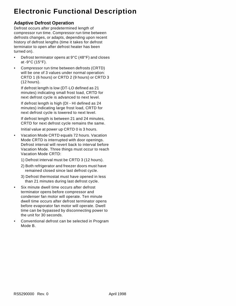
Adaptive Defrost OperationDefrost occurs after predetermined length ofcompressor run time. Compressor run time betweendefrosts changes, or adapts, depending upon recenthistory of defrost lengths (time it takes for defrostterminator to open after defrost heater has beenturned on).
• Defrost terminator opens at 9°C (48°F) and closesat -9°C (15°F).
• Compressor run time between defrosts (CRTD)will be one of 3 values under normal operation:CRTD 1 (6 hours) or CRTD 2 (9 hours) or CRTD 3(12 hours).
If defrost length is low (DT-LO defined as 21minutes) indicating small frost load, CRTD fornext defrost cycle is advanced to next level.
If defrost length is high (DI - HI defined as 24minutes) indicating large frost load, CRTD fornext defrost cycle is lowered to next level.
If defrost length is between 21 and 24 minutes,CRTD for next defrost cycle remains the same.
Initial value at power up CRTD 0 is 3 hours.
• Vacation Mode CRTD equals 72 hours. VacationMode CRTD is interrupted with door openings.Defrost interval will revert back to interval beforeVacation Mode. Three things must occur to reachVacation Mode CRTD:
1) Defrost interval must be CRTD 3 (12 hours).
2) Both refrigerator and freezer doors must haveremained closed since last defrost cycle.
3) Defrost thermostat must have opened in lessthan 21 minutes during last defrost cycle.
• Six minute dwell time occurs after defrostterminator opens before compressor andcondenser fan motor will operate. Ten minutedwell time occurs after defrost terminator opensbefore evaporator fan motor will operate. Dwelltime can be bypassed by disconnecting power tothe unit for 30 seconds.
• Conventional defrost can be selected in ProgramMode B.
Electronic Functional Description
April 1998 RS5290000 Rev. 0
Program ModeAccessing Program ModeTwo programming modes are available. Mode Aallows reading refrigerator and freezer thermistortemperatures. Mode B is used for all otherprogrammable functions.
1. Open refrigerator door.2. Press * pad.3. Press Vacation pad.4. Press the following sequence of pads within 6
seconds: Max Cool, Fast Freeze, Max Cool, FastFreeze.
5. When access is granted, tone will sound threetime and control will be in Program Mode A.Indicator light will illuminate.
6. Toggle to Program Mode B by pressing * pad.Indicator light is off.
EEPROM Update in Control MemoryEEPROM is permanent programmable memory of thecontrol panel.
• Entry tone, door audio alarm and status are storedin EEPROM after control panel is deactivated.
• Clean coil status is stored in EEPROM after everydefrost cycle as time until clean coil alarm isactivated.
• Information stored in EEPROM memory is notaffected by power loss.
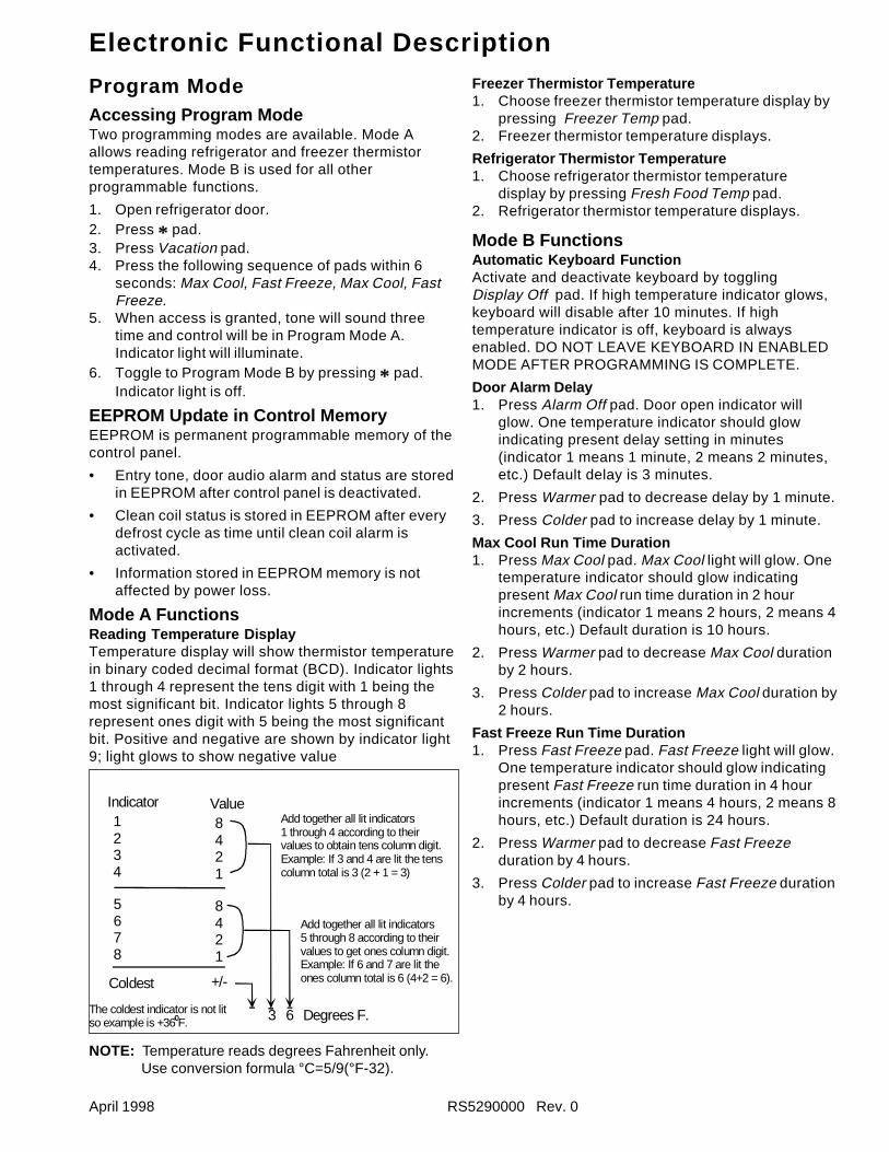
Mode A FunctionsReading Temperature DisplayTemperature display will show thermistor temperaturein binary coded decimal format (BCD). Indicator lights1 through 4 represent the tens digit with 1 being themost significant bit. Indicator lights 5 through 8represent ones digit with 5 being the most significantbit. Positive and negative are shown by indicator light9; light glows to show negative value
Indicator Value1234
8421
5678
8421
Coldest +/-
3 6 Degrees F.
Add together all lit indicators1 through 4 according to theirvalues to obtain tens column digit.Example: If 3 and 4 are lit the tenscolumn total is 3 (2 + 1 = 3)
Add together all lit indicators5 through 8 according to their values to get ones column digit.Example: If 6 and 7 are lit the ones column total is 6 (4+2 = 6).
The coldest indicator is not litso example is +36 F.
NOTE: Temperature reads degrees Fahrenheit only.Use conversion formula °C=5/9(°F-32).
Freezer Thermistor Temperature1. Choose freezer thermistor temperature display by
pressing Freezer Temp pad.2. Freezer thermistor temperature displays.
Refrigerator Thermistor Temperature1. Choose refrigerator thermistor temperature
display by pressing Fresh Food Temp pad.2. Refrigerator thermistor temperature displays.
Mode B FunctionsAutomatic Keyboard FunctionActivate and deactivate keyboard by togglingDisplay Off pad. If high temperature indicator glows,keyboard will disable after 10 minutes. If hightemperature indicator is off, keyboard is alwaysenabled. DO NOT LEAVE KEYBOARD IN ENABLEDMODE AFTER PROGRAMMING IS COMPLETE.
Door Alarm Delay1. Press Alarm Off pad. Door open indicator will
glow. One temperature indicator should glowindicating present delay setting in minutes(indicator 1 means 1 minute, 2 means 2 minutes,etc.) Default delay is 3 minutes.
2. Press Warmer pad to decrease delay by 1 minute.
3. Press Colder pad to increase delay by 1 minute.
Max Cool Run Time Duration1. Press Max Cool pad. Max Cool light will glow. One
temperature indicator should glow indicatingpresent Max Cool run time duration in 2 hourincrements (indicator 1 means 2 hours, 2 means 4hours, etc.) Default duration is 10 hours.
2. Press Warmer pad to decrease Max Cool durationby 2 hours.
3. Press Colder pad to increase Max Cool duration by2 hours.
Fast Freeze Run Time Duration1. Press Fast Freeze pad. Fast Freeze light will glow.
One temperature indicator should glow indicatingpresent Fast Freeze run time duration in 4 hourincrements (indicator 1 means 4 hours, 2 means 8hours, etc.) Default duration is 24 hours.
2. Press Warmer pad to decrease Fast Freezeduration by 4 hours.
3. Press Colder pad to increase Fast Freeze durationby 4 hours.
Electronic Functional Description
RS5290000 Rev. 0 April 1998
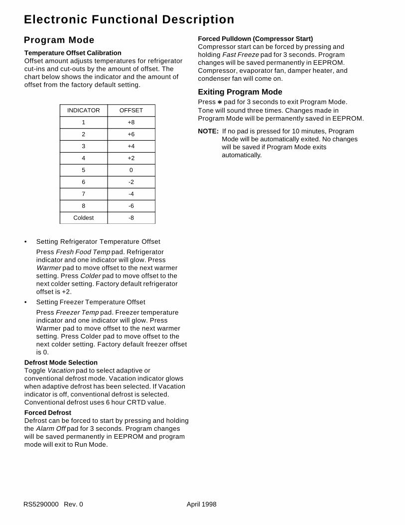
Temperature Offset CalibrationOffset amount adjusts temperatures for refrigeratorcut-ins and cut-outs by the amount of offset. Thechart below shows the indicator and the amount ofoffset from the factory default setting.
INDICATOR OFFSET
1 +8
2 +6
3 +4
4 +2
5 0
6 -2
7 -4
8 -6
Coldest -8
• Setting Refrigerator Temperature Offset
Press Fresh Food Temp pad. Refrigeratorindicator and one indicator will glow. PressWarmer pad to move offset to the next warmersetting. Press Colder pad to move offset to thenext colder setting. Factory default refrigeratoroffset is +2.
• Setting Freezer Temperature Offset
Press Freezer Temp pad. Freezer temperatureindicator and one indicator will glow. PressWarmer pad to move offset to the next warmersetting. Press Colder pad to move offset to thenext colder setting. Factory default freezer offsetis 0.
Defrost Mode SelectionToggle Vacation pad to select adaptive orconventional defrost mode. Vacation indicator glowswhen adaptive defrost has been selected. If Vacationindicator is off, conventional defrost is selected.Conventional defrost uses 6 hour CRTD value.
Forced DefrostDefrost can be forced to start by pressing and holdingthe Alarm Off pad for 3 seconds. Program changeswill be saved permanently in EEPROM and programmode will exit to Run Mode.
Program Mode Forced Pulldown (Compressor Start)Compressor start can be forced by pressing andholding Fast Freeze pad for 3 seconds. Programchanges will be saved permanently in EEPROM.Compressor, evaporator fan, damper heater, andcondenser fan will come on.
Exiting Program ModePress * pad for 3 seconds to exit Program Mode.Tone will sound three times. Changes made inProgram Mode will be permanently saved in EEPROM.
NOTE: If no pad is pressed for 10 minutes, ProgramMode will be automatically exited. No changeswill be saved if Program Mode exitsautomatically.
Electronic Functional Description
April 1998 RS5290000 Rev. 0
2. Check for voltage on terminal E7 on high voltageboard. Output voltage should toggle with togglingof light switch. If output voltage does not toggle,high voltage board needs replacing.
3. If terminal 7 on high voltage board changes withopening and closing of door, orange wire in lowvoltage harness is broken (check for continuitybetween pin 7 on high voltage board and pin 10 onlow voltage board) or low voltage board needsreplacing.
1. Check for line voltage on terminal E8 on highvoltage board. With freezer door open, readingshould be 230 VAC. With door closed, readingshould be approximately 0 VAC. If voltage doesnot change with light switch and light switch isturning light off and on, violet/white wire is brokenbetween switch and high voltage board.
2. Check for voltage on pin 7 on pin connector of highvoltage board. Output voltage should toggle withtoggling of light switch. If it does not toggle, highvoltage board needs replacing.
3. If voltage on pin 7 on pin connector on high voltageboard changes with opening and closing of door,orange wire in low voltage harness is broken(check for continuity between pin 7 on high voltagepin connector and pin 10 on low voltage board) orlow voltage board needs replacing.
Electronic Testing
Electronic Testing ModeForced Defrost Start1. Press * pad to activate control panel.
2. Simultaneously press and hold Max Cool andDisplay Off pads for 3 seconds.
Forced Compressor Start1. Press * pad to activate control panel.
2. Simultaneously press and hold Fast Freeze padand Display Off pad for 3 seconds.
Open Thermistor Detect
Alarm sounds and freezer or refrigerator indicator lightshows and temperature indicators 4 through 7 will turnon in sequence if either thermistor circuit opens. Referto Temperature Control Operation Section andElectronic Testing Section.
1. Press Alarm Off pad to turn off alarm.
2. Alarm will retest for normal operation. If conditionhas not been corrected, alarm will sound again.
Evaporator Fan SuppressionThe evaporator fan will turn off every time eitherrefrigerator or freezer door is open.
To test if this function is operating:
1. Perform forced pull down procedure as notedabove –evaporator fan should be on.
2. Open the refrigerator or freezer door–the fanshould turn off.
3. Push the light switch off–the evaporator fanshould start.
If fan does not toggle off and on when refrigeratorlight switch is turned off and on and it has beendetermined evaporator fan motor is operational,perform following tests to determine failure:
1. Check for line voltage on terminal E7 on highvoltage board. With refrigerator door open(refrigerator light ON) reading should be 230 VAC.With refrigerator door closed (refrigerator lightOFF) reading should be approximately 0 VAC.
If voltage does not change with light switch andlight switch is turning light off and on, red/whitewire is broken between switch and high voltageboard.
DANGER!To avoid electrical shock, personal injury or death,avoid contacting high voltage parts. Disconnect powerto unit and discharge capacitor before handling.
DANGER!To avoid electrical shock, personal injury or death,avoid contacting high voltage parts. Disconnect powerto unit and discharge capacitor before handling.
Electronic Functional Description
RS5290000 Rev. 0 April 1998
Electronic Functional Description
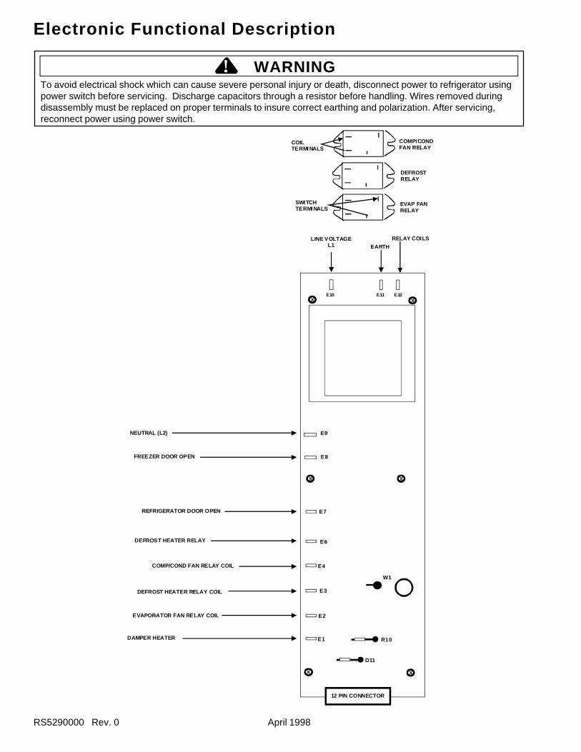
To avoid electrical shock which can cause severe personal injury or death, disconnect power to refrigerator usingpower switch before servicing. Discharge capacitors through a resistor before handling. Wires removed duringdisassembly must be replaced on proper terminals to insure correct earthing and polarization. After servicing,reconnect power using power switch.
E10 E11 E12
E9
E8
E7
E6
E4
E3
E2
E1 R10
D11
XX
W1
NEUTRAL (L2)
FREEZER DOOR OPEN
REFRIGERATOR DOOR OPEN
DEFROST HEATER RELAY
COMP/COND FAN RELAY COIL
DEFROST HEATER RELAY COIL
EVAPORATOR FAN RELAY COIL
DAMPER HEATER
12 PIN CONNECTOR
XX
XX
LINE VOLTAGEL1 EARTH
RELAY COILS
COMP/CONDFAN RELAY
DEFROSTRELAY
EVAP FANRELAY
COILTERMI NALS
SWITCHTERMI NALS
! WARNING
April 1998 RS5290000 Rev. 0
Electronic Functional Description
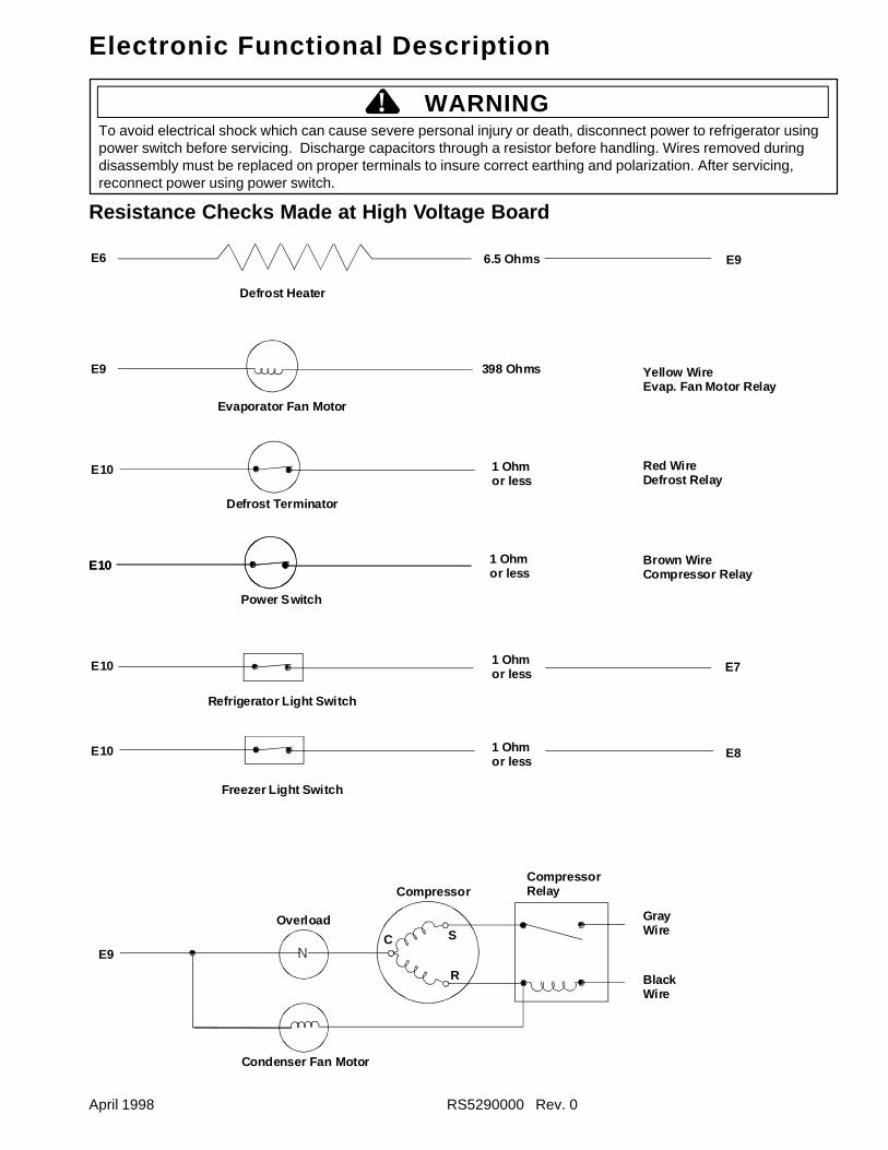
E6
E9
E10
E10
E10
E10
Defrost Heater
6.5 Ohms E9
398 Ohms Yellow Wire Evap. Fan Motor Relay
1 Ohmor less
Evaporator Fan Motor
Defrost Terminator
E10
Red WireDefrost Relay
Power Switch
1 Ohmor less
Brown WireCompressor Relay
Refrigerator Light Switch
1 Ohmor less E7
Freezer Light Switch
1 Ohmor less
E8
N
v
E9
Overload
Condenser Fan Motor
Compressor
C S
R
CompressorRelay
GrayWire
BlackWire
Resistance Checks Made at High Voltage Board
To avoid electrical shock which can cause severe personal injury or death, disconnect power to refrigerator usingpower switch before servicing. Discharge capacitors through a resistor before handling. Wires removed duringdisassembly must be replaced on proper terminals to insure correct earthing and polarization. After servicing,reconnect power using power switch.
! WARNING
RS5290000 Rev. 0 April 1998
Electronic Functional Description
Refrigeration and Defrost Component Checks Made at High Voltage Board
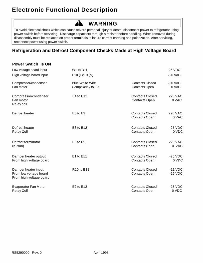
Power Swtich Is ONLow voltage board input W1 to D11 -25 VDC
High voltage board input E10 (L)/E9 (N) 220 VAC
Compressor/condenser Blue/White Wire Contacts Closed 220 VACFan motor Comp/Relay to E9 Contacts Open 0 VAC
Compressor/condenser E4 to E12 Contacts Closed 220 VACFan motor Contacts Open 0 VACRelay coil
Defrost heater E6 to E9 Contacts Closed 220 VACContacts Open 0 VAC
Defrost heater E3 to E12 Contacts Closed -25 VDCRelay Coil Contacts Open 0 VDC
Defrost terminator E6 to E9 Contacts Closed 220 VAC(Klixon) Contacts Open 0 VAC
Damper heater output E1 to E11 Contacts Closed -25 VDCFrom high voltage board Contacts Open 0 VDC
Damper heater input R10 to E11 Contacts Closed -11 VDCFrom low voltage board Contacts Open -25 VDCFrom high voltage board
Evaporator Fan Motor E2 to E12 Contacts Closed -25 VDCRelay Coil Contacts Open 0 VDC
To avoid electrical shock which can cause severe personal injury or death, disconnect power to refrigerator usingpower switch before servicing. Discharge capacitors through a resistor before handling. Wires removed duringdisassembly must be replaced on proper terminals to insure correct earthing and polarization. After servicing,reconnect power using power switch.
! WARNING
April 1998 RS5290000 Rev. 0
Electronic Functional Description
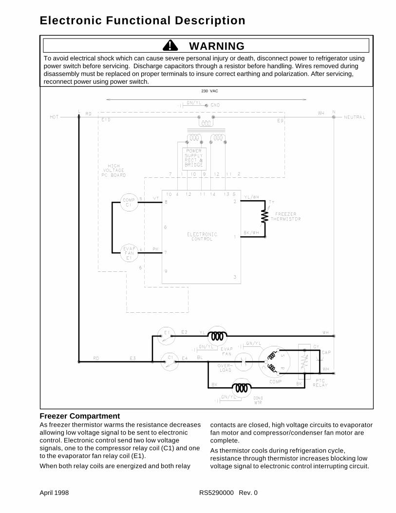
Freezer CompartmentAs freezer thermistor warms the resistance decreasesallowing low voltage signal to be sent to electroniccontrol. Electronic control send two low voltagesignals, one to the compressor relay coil (C1) and oneto the evaporator fan relay coil (E1).
When both relay coils are energized and both relay
contacts are closed, high voltage circuits to evaporatorfan motor and compressor/condenser fan motor arecomplete.
As thermistor cools during refrigeration cycle,resistance through thermistor increases blocking lowvoltage signal to electronic control interrupting circuit.
To avoid electrical shock which can cause severe personal injury or death, disconnect power to refrigerator usingpower switch before servicing. Discharge capacitors through a resistor before handling. Wires removed duringdisassembly must be replaced on proper terminals to insure correct earthing and polarization. After servicing,reconnect power using power switch.
! WARNING
230 VAC
RS5290000 Rev. 0 April 1998
Electronic Functional Description
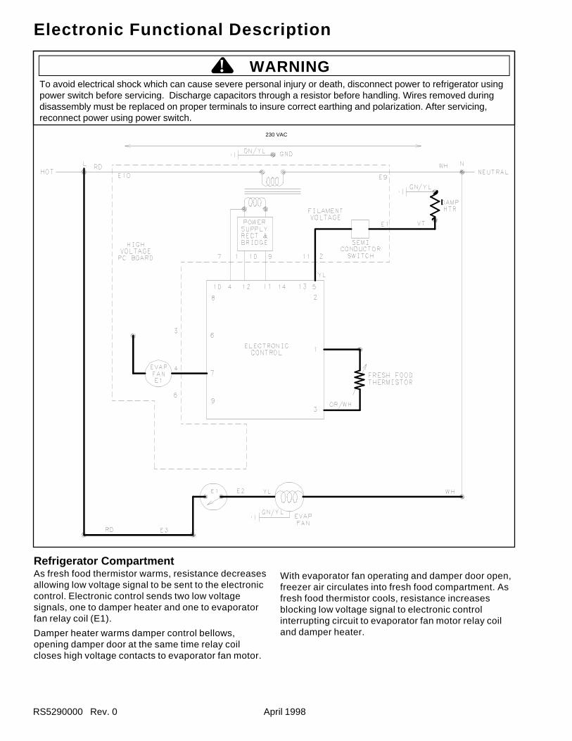
Refrigerator CompartmentAs fresh food thermistor warms, resistance decreasesallowing low voltage signal to be sent to the electroniccontrol. Electronic control sends two low voltagesignals, one to damper heater and one to evaporatorfan relay coil (E1).
Damper heater warms damper control bellows,opening damper door at the same time relay coilcloses high voltage contacts to evaporator fan motor.
With evaporator fan operating and damper door open,freezer air circulates into fresh food compartment. Asfresh food thermistor cools, resistance increasesblocking low voltage signal to electronic controlinterrupting circuit to evaporator fan motor relay coiland damper heater.
To avoid electrical shock which can cause severe personal injury or death, disconnect power to refrigerator usingpower switch before servicing. Discharge capacitors through a resistor before handling. Wires removed duringdisassembly must be replaced on proper terminals to insure correct earthing and polarization. After servicing,reconnect power using power switch.
! WARNING
230 VAC
April 1998 RS5290000 Rev. 0
Electronic Functional Description
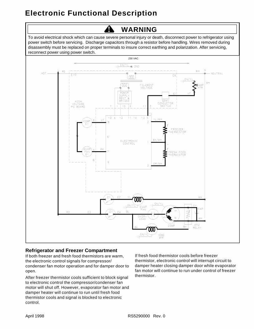
Refrigerator and Freezer CompartmentIf both freezer and fresh food thermistors are warm,the electronic control signals for compressor/condenser fan motor operation and for damper door toopen.
After freezer thermistor cools sufficient to block signalto electronic control the compressor/condenser fanmotor will shut off. However, evaporator fan motor anddamper heater will continue to run until fresh foodthermistor cools and signal is blocked to electroniccontrol.
If fresh food thermistor cools before freezerthermistor, electronic control will interrupt circuit todamper heater closing damper door while evaporatorfan motor will continue to run under control of freezerthermistor.
To avoid electrical shock which can cause severe personal injury or death, disconnect power to refrigerator usingpower switch before servicing. Discharge capacitors through a resistor before handling. Wires removed duringdisassembly must be replaced on proper terminals to insure correct earthing and polarization. After servicing,reconnect power using power switch.
! WARNING
230 VAC
RS5290000 Rev. 0 April 1998
Electronic Functional Description
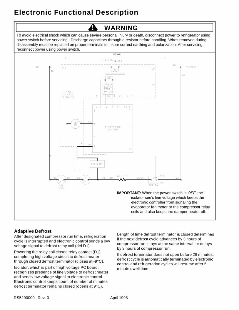
Adaptive DefrostAfter designated compressor run time, refrigerationcycle is interrupted and electronic control sends a lowvoltage signal to defrost relay coil (def D1).
Powering the relay coil closed relay contact (D1)completing high voltage circuit to defrost heaterthrough closed defrost terminator (closes at -9°C).
Isolator, which is part of high voltage PC board,recognizes presence of line voltage to defrost heaterand sends low voltage signal to electronic control.Electronic control keeps count of number of minutesdefrost terminator remains closed (opens at 9°C).
Length of time defrost terminator is closed determinesif the next defrost cycle advances by 3 hours ofcompressor run, stays at the same interval, or delaysby 3 hours of compressor run.
If defrost terminator does not open before 29 minutes,defrost cycle is automatically terminated by electroniccontrol and refrigeration cycles will resume after 6minute dwell time.
IMPORTANT: When the power switch is OFF, theisolator see’s line voltage which keeps theelectronic controller from signaling theevaporator fan motor or the compressor relaycoils and also keeps the damper heater off.
To avoid electrical shock which can cause severe personal injury or death, disconnect power to refrigerator usingpower switch before servicing. Discharge capacitors through a resistor before handling. Wires removed duringdisassembly must be replaced on proper terminals to insure correct earthing and polarization. After servicing,reconnect power using power switch.
! WARNING
230 VAC
April 1998 RS590000 Rev. 0
Component TestingComponent Description Test ProceduresCapacitor
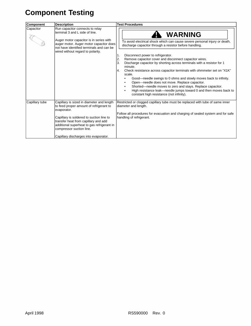
Run capacitor connects to relayterminal 3 and L side of line.
Auger motor capacitor is in series withauger motor. Auger motor capacitor doesnot have identified terminals and can bewired without regard to polarity.
1. Disconnect power to refrigerator.2. Remove capacitor cover and disconnect capacitor wires.3. Discharge capacitor by shorting across terminals with a resistor for 1
minute.4. Check resistance across capacitor terminals with ohmmeter set on “X1K”
scale.• Good—needle swings to 0 ohms and slowly moves back to infinity.• Open—needle does not move. Replace capacitor.• Shorted—needle moves to zero and stays. Replace capacitor.• High resistance leak—needle jumps toward 0 and then moves back to
constant high resistance (not infinity).
Capillary tube Capillary is sized in diameter and lengthto feed proper amount of refrigerant toevaporator.
Capillary is soldered to suction line totransfer heat from capillary and addadditional superheat to gas refrigerant incompressor suction line.
Capillary discharges into evaporator.
Restricted or clogged capillary tube must be replaced with tube of same innerdiameter and length.
Follow all procedures for evacuation and charging of sealed system and for safehandling of refrigerant.
WARNING!To avoid electrical shock which can cause severe personal injury or death,discharge capacitor through a resistor before handling.
RS590000 Rev. 0 April 1998
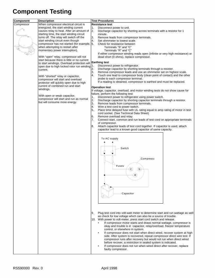
Component TestingComponent Description Test ProceduresCompressor When compressor electrical circuit is
energized, the start winding currentcauses relay to heat. After an amount ofstarting time, the start winding circuitturns off. The relay will switch off thestart winding circuit even thoughcompressor has not started (for example,when attempting to restart aftermomentary power interruption).
With “open” relay, compressor will notstart because there is little or no currentto start windings. Overload protection willopen due to high locked rotor run windingcurrent.
With “shorted” relay or capacitor,compressor will start and overloadprotector will quickly open due to highcurrent of combined run and startwindings.
With open or weak capacitor,compressor will start and run as normalbut will consume more energy.
Resistance test1. Disconnect power to unit.2. Discharge capacitor by shorting across terminals with a resistor for 1
minute.3. Remove leads from compressor terminals.4. Set ohmmeter to lowest scale.5. Check for resistance between Terminals “S” and “C” Terminals “R” and “C”
If either compressor winding reads open (infinite or very high resistance) ordead short (0 ohms), replace compressor.
Earthing test1. Disconnect power to refrigerator.2. Discharge capacitor by shorting terminals through a resister.3. Remove compressor leads and use an ohmmeter set on highest scale.4. Touch one lead to compressor body (clean point of contact) and the other
probe to each compressor terminal.If a reading is obtained, compressor is earthed and must be replaced.
Operation testIf voltage, capacitor, overload, and motor winding tests do not show cause forfailure, perform the following test:1. Disconnect power to refrigerator using power switch.2. Discharge capacitor by shorting capacitor terminals through a resistor.3. Remove leads from compressor terminals.4. Wire a test cord to power switch.5. Place time delayed fuse with UL rating equal to amp rating of motor in test
cord socket. (See Technical Data Sheet)6. Remove overload and relay.7. Connect start, common and run leads of test cord on appropriate terminals
of compressor.8. Attach capacitor leads of test cord together. If capacitor is used, attach
capacitor lead to a known good capacitor of same capacity.
9. Plug test cord into volt-watt meter to determine start and run wattage as wellas check for low voltage which can also be a source of trouble.
10. With power to volt-meter, press start cord switch and release.• If compressor motor starts and draws normal wattage, compressor is
okay and trouble is in capacitor, relay/overload, freezer temperaturecontrol, or elsewhere in system.
• If compressor does not start when direct wired, recover system at highside. After system is recovered, repeat compressor direct wire test. Ifcompressor runs after recovery but would not run when direct wiredbefore recover, a restriction in sealed system is indicated.
• If compressor does not run when wired direct after recover, replacefaulty compressor.
C
R
SFuses
Capacitor
Compresso
Switch
To AC supply
April 1998 RS590000 Rev. 0
Component TestingComponent Description Test ProceduresCondenser Condenser is a tube and wire
construction and is located incompressor compartment.
Condenser is on the high pressuredischarge side of compressor.Condenser function is to transfer heatabsorbed by refrigerant to ambient.
Higher pressure gas is routed tocondenser where, as gas temperature isreduced, gas condenses into a highpressure liquid state. Heat transfer takesplace because discharged gas is at ahigher temperature than air that ispassing over condenser. It is veryimportant that adequate air flow overcondenser is maintained.
Condenser is air cooled by condenserfan motor. If efficiency of heat transferfrom condenser to surrounding air isimpaired, condensing temperaturebecomes higher. High liquid temperaturemeans the liquid will not remove as muchheat during boiling in evaporator asunder normal conditions. This would beindicated by higher than normal headpressures, long run time, and highwattage. Remove any lint accumulation,etc. that would restrict normal airmovement through condenser.
From condenser the refrigerant flows intoa post condenser loop which helpscontrol exterior condensation on flange,center mullion, around freezer door andthen through the drier to the evaporatorand into the compressor through thesuction line.
Leaks in condenser can usually be detected by using an electronic leak detectoror soap solution. Look for signs of compressor oil when checking for leaks. Acertain amount of compressor oil is circulated with refrigerant.
Leaks in post condenser loop are rare because loop is a one-piece copper tube.
For minute leaks1. Separate condenser from rest of refrigeration system and pressurize
condenser up to a maximum of 16 bars (235 PSI) with a refrigerant and drynitrogen combination.
2. Recheck for leaks.
Damper Control Damper control balances the air deliverybetween refrigerator and freezercompartments.Integral capillary activates dampercontrol and door closes restricting flow ofair from freezer compartment torefrigerator compartment.There are no electrical connections todamper control on non-electronic units.See Electronic Functional Description forexplanation of damper control onelectronic units.
Subject capillary to appropriate temperature (see tech sheet for model beingserviced).Damper door should close to within 6 mm of completely shut.
If altitude adjustment is required, turn altitude adjustment screw 1/8 turnclockwise for each 305 meters increase in altitude.
WARNING!To avoid severe personal injury or death observe the following:
• Protect against a sudden eruption if high pressures are requiredfor leak checking.
• Do not use high pressure compressed gases in refrigerationsystems without a reliable pressure regulator and pressure reliefvalve in the lines.
RS590000 Rev. 0 April 1998
Component TestingComponent Description Test Procedures
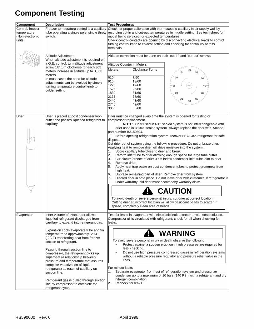
Freezer temperature control is a capillarytube operating a single pole, single throwswitch.
Check for proper calibration with thermocouple capillary in air supply well byrecording cut-in and cut-out temperatures in middle setting. See tech sheet formodel being serviced for expected temperatures.Check control contacts are opening by disconnecting electrical leads to controlturning control knob to coldest setting and checking for continuity acrossterminals.
Altitude correction must be done on both “cut-in” and “cut-out” screws.
Altitude Counter in Meters
Meters Clockwise Turns
Control, freezertemperature(Non-electronicunits)
Altitude AdjustmentWhen altitude adjustment is required ona G.E. control, turn altitude adjustmentscrew 1/7 turn clockwise for each 305meters increase in altitude up to 3,050meters.In most cases the need for altitudeadjustments can be avoided by simplyturning temperature control knob tocolder setting.
6109151220152518302135244027453050
7/6013/6019/6025/6031/6037/6043/6049/6055/60
Drier Drier is placed at post condenser loopoutlet and passes liquefied refrigerant tocapillary.
Drier must be changed every time the system is opened for testing orcompressor replacement.
NOTE: Drier used in R12 sealed system is not interchangeable with drier used in R134a sealed system. Always replace the drier with Amana
part number B2150504.Before opening refrigeration system, recover HFC134a refrigerant for safe
disposal.Cut drier out of system using the following procedure. Do not unbraze drier.Applying heat to remove drier will drive moisture into the system.1. Score capillary tube close to drier and break.2. Reform inlet tube to drier allowing enough space for large tube cutter.3. Cut circumference of drier 3 cm below condenser inlet tube joint to drier.4. Remove drier.5. Apply heat trap paste on post condenser tubes to protect grommets from
high heat.6. Unbraze remaining part of drier. Remove drier from system.7. Discard drier in safe place. Do not leave drier with customer. If refrigerator is
under warranty, old drier must accompany warranty claim.
Evaporator Inner volume of evaporator allowsliquefied refrigerant discharged fromcapillary to expand into refrigerant gas.
Expansion cools evaporate tube and fintemperature to approximately -29°C(-20°F) transferring heat from freezersection to refrigerant.
Passing through suction line tocompressor, the refrigerant picks upsuperheat (a relationship betweenpressure and temperature that assurescomplete vaporization of liquidrefrigerant) as result of capillary onsuction line.
Refrigerant gas is pulled through suctionline by compressor to complete therefrigerant cycle.
Test for leaks in evaporator with electronic leak detector or with soap solution.Compressor oil is circulated with refrigerant; check for oil when checking forleaks.
WARNING! To avoid severe personal injury or death observe the following:
• Protect against a sudden eruption if high pressures are required forleak checking.
• Do not use high pressure compressed gases in refrigeration systemswithout a reliable pressure regulator and pressure relief valve in thelines.
For minute leaks1. Separate evaporator from rest of refrigeration system and pressurize
condenser up to a maximum of 10 bars (140 PSI) with a refrigerant and drynitrogen combination.
2. Recheck for leaks.
CAUTION!To avoid death or severe personal injury, cut drier at correct location.Cutting drier at incorrect location will allow desiccant beads to scatter. Ifspilled, completely clean area of beads.
005
10
15
20
2530
35
40
45
50
55
April 1998 RS590000 Rev. 0
Component TestingFusible link Fusible link is part of evaporator heater
wiring harness and is in a series circuitwith defrost terminator, defrost heater,and evaporator fan motor.
If the defrost terminator fails to open andtemperature increases to fusible link,fuse will open breaking circuit so defrostheater will be shut down.
If fusible link interrupts opens, evaporator heater wiring harness must bereplaced.
Be sure harness is wire tied against evaporator heater over white mark onevaporator heater.
Heater, door Applied to back of ice and water cavity tohelp prevent condensation from formingon face of cavity.
Some models have spare heater foamed in place at factory. See tech sheet formodel being serviced.
Check resistance across heater (for resistance values see tech sheet for modelbeing serviced).
Heater, evaporator(defrost)
Activated when defrost thermostat oradaptive defrost control completes thecircuit through the heater.
Check resistance across heater.
To check defrost system1. Thermocouple defrost thermostat and plugging refrigerator into wattmeter.2. Force into defrost mode (see section on electronic testing). Wattmeter
should read specified watts (according to tech sheet).3. When defrost thermostat reaches specified temperature (see tech sheet)
±5°F; thermostat should interrupt power to heater.Ice Maker See “Ice Maker” section for service
information.Motor, auger Located behind ice bucket. Drives helix
auger and cube crusher.
PSC (Permanent Split Capacitor) motorrequiring a run capacitor.
Controlled by ice actuator switch inseries with freezer door auger interlockswitch and cube/crushed ice switch.
Internal overload trips out afterapproximately 90 second of continuousrun and resets in approximately 3minutes.
Disconnect power and ohm winding and check for earthing.
Crushed/Cube Dispensing Models:At room ambient temperature check resistance between wire leads (seetech sheet for colors on unit being serviced).
Cube Dispensing Models:At room ambient temperature check resistance cross motor windings. Forresistance values see tech sheet for model being serviced.
Motor, condenser Condenser fan moves cooling air acrosscondenser coil and compressor body.
Condenser fan motor is in parallel circuitwith compressor.
Check resistance across winding (for resistance value see tech sheet for modelbeing serviced).
Motor,evaporator fan
Evaporator motor moves air acrossevaporator coil and throughoutrefrigerator.
Evaporator fan is in a series circuit withtemperature control, defrost terminator,and defrost heater.
1. Disconnect power to unit.2. Disconnect fan motor leads.3. Check resistance from earth connection solder. Trace to motor frame must
not exceed .05 ohms.4. Check for voltage at connector to motor with terminator and temperature
control closed.
Overload/Relay Overload is a temperature and currentsensing device.
Overload opens when high current orhigh compressor temperature is sensed.
After overload opens, reset can requireup to two hours depending on ambienttemperature and residual heat load incompressor.
Relay (See PTC Relay)
1. Disconnect power to the refrigerator.2. Remove relay cover and pull relay off compressor. Pull overload protector
off compressor common terminal.3. With ohmmeter, check the resistance between male terminal and female
pin receptacle terminal which pushes onto compressor common terminal. Atambient room temperature overload protector should have less than 1 ohmresistance. An open overload protector will have infinite resistance.
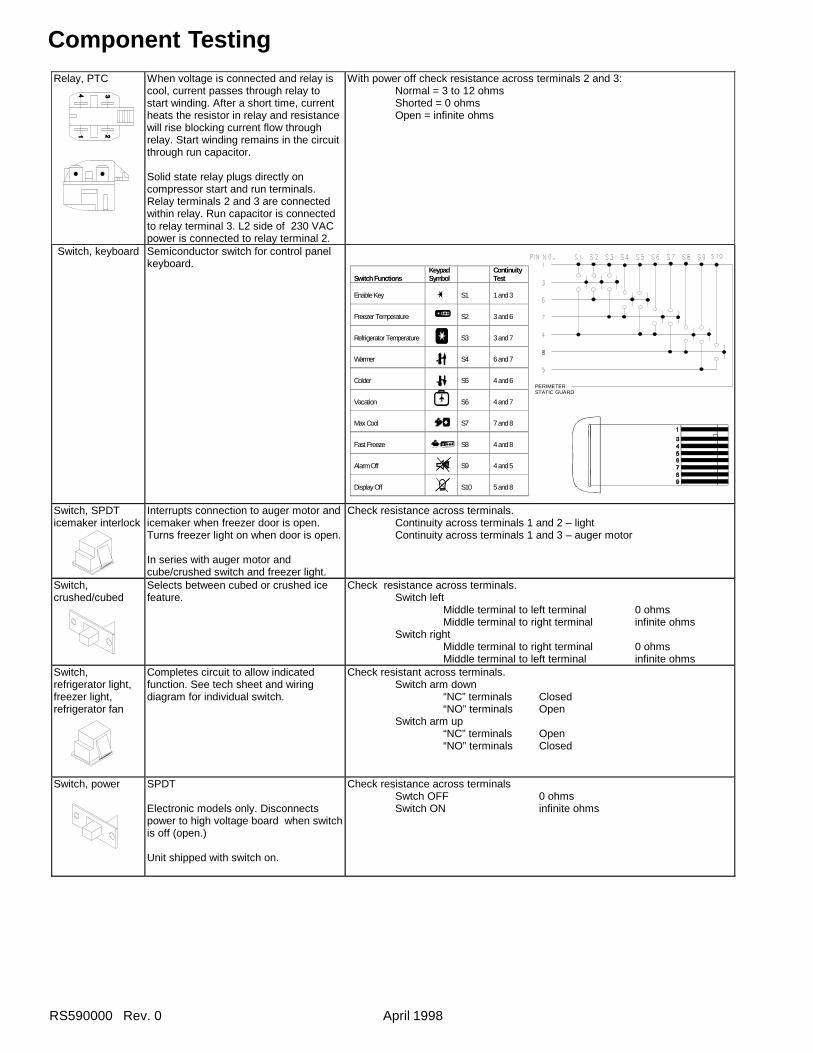
RS590000 Rev. 0 April 1998
Component Testing
PERIMETERSTATIC GUARD
Switch FunctionsKeypadSymbol
ContinuityTest
Enable Key S1 1 and 3
Freezer Temperature S2 3 and 6
Refrigerator Temperature S3 3 and 7
Warmer S4 6 and 7
Colder S5 4 and 6
Vacation S6 4 and 7
Max Cool S7 7 and 8
Fast Freeze S8 4 and 8
Alarm Off S9 4 and 5
Display Off S10 5 and 8
Relay, PTC When voltage is connected and relay iscool, current passes through relay tostart winding. After a short time, currentheats the resistor in relay and resistancewill rise blocking current flow throughrelay. Start winding remains in the circuitthrough run capacitor.
Solid state relay plugs directly oncompressor start and run terminals.Relay terminals 2 and 3 are connectedwithin relay. Run capacitor is connectedto relay terminal 3. L2 side of 230 VACpower is connected to relay terminal 2.
With power off check resistance across terminals 2 and 3:Normal = 3 to 12 ohmsShorted = 0 ohmsOpen = infinite ohms
Switch, keyboard Semiconductor switch for control panelkeyboard.
Switch, SPDTicemaker interlock
Interrupts connection to auger motor andicemaker when freezer door is open.Turns freezer light on when door is open.
In series with auger motor andcube/crushed switch and freezer light.
Check resistance across terminals.Continuity across terminals 1 and 2 – lightContinuity across terminals 1 and 3 – auger motor
Switch,crushed/cubed
Selects between cubed or crushed icefeature.
Check resistance across terminals.Switch left
Middle terminal to left terminal 0 ohmsMiddle terminal to right terminal infinite ohms
Switch rightMiddle terminal to right terminal 0 ohmsMiddle terminal to left terminal infinite ohms
Switch,refrigerator light,freezer light,refrigerator fan
Completes circuit to allow indicatedfunction. See tech sheet and wiringdiagram for individual switch.
Check resistant across terminals.Switch arm down
“NC” terminals Closed“NO” terminals Open
Switch arm up“NC” terminals Open“NO” terminals Closed
Switch, power SPDT
Electronic models only. Disconnectspower to high voltage board when switchis off (open.)
Unit shipped with switch on.
Check resistance across terminalsSwtch OFF 0 ohmsSwitch ON infinite ohms
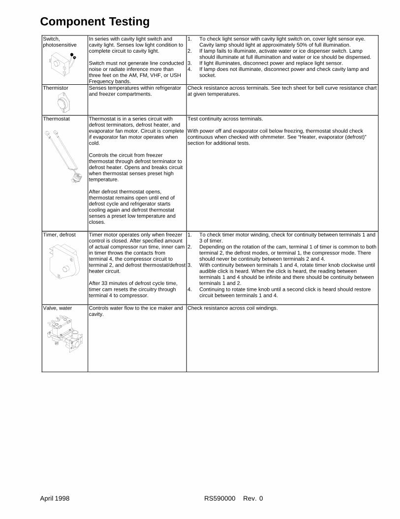
April 1998 RS590000 Rev. 0
Component TestingSwitch,photosensitive
In series with cavity light switch andcavity light. Senses low light condition tocomplete circuit to cavity light.
Switch must not generate line conductednoise or radiate inference more thanthree feet on the AM, FM, VHF, or USHFrequency bands.
1. To check light sensor with cavity light switch on, cover light sensor eye.Cavity lamp should light at approximately 50% of full illumination.
2. If lamp fails to illuminate, activate water or ice dispenser switch. Lampshould illuminate at full illumination and water or ice should be dispensed.
3. If light illuminates, disconnect power and replace light sensor.4. If lamp does not illuminate, disconnect power and check cavity lamp and
socket.
Thermistor Senses temperatures within refrigeratorand freezer compartments.
Check resistance across terminals. See tech sheet for bell curve resistance chartat given temperatures.
Thermostat Thermostat is in a series circuit withdefrost terminators, defrost heater, andevaporator fan motor. Circuit is completeif evaporator fan motor operates whencold.
Controls the circuit from freezerthermostat through defrost terminator todefrost heater. Opens and breaks circuitwhen thermostat senses preset hightemperature.
After defrost thermostat opens,thermostat remains open until end ofdefrost cycle and refrigerator startscooling again and defrost thermostatsenses a preset low temperature andcloses.
Test continuity across terminals.
With power off and evaporator coil below freezing, thermostat should checkcontinuous when checked with ohmmeter. See “Heater, evaporator (defrost)”section for additional tests.
Timer, defrost Timer motor operates only when freezercontrol is closed. After specified amountof actual compressor run time, inner camin timer throws the contacts fromterminal 4, the compressor circuit toterminal 2, and defrost thermostat/defrostheater circuit.
After 33 minutes of defrost cycle time,timer cam resets the circuitry throughterminal 4 to compressor.
1. To check timer motor winding, check for continuity between terminals 1 and3 of timer.
2. Depending on the rotation of the cam, terminal 1 of timer is common to bothterminal 2, the defrost modes, or terminal 1, the compressor mode. Thereshould never be continuity between terminals 2 and 4.
3. With continuity between terminals 1 and 4, rotate timer knob clockwise untilaudible click is heard. When the click is heard, the reading betweenterminals 1 and 4 should be infinite and there should be continuity betweenterminals 1 and 2.
4. Continuing to rotate time knob until a second click is heard should restorecircuit between terminals 1 and 4.
Valve, water Controls water flow to the ice maker andcavity.
Check resistance across coil windings.
RS5290000 Rev. 0 April 1998
Product Design
Refrigeration SystemCompressor forces high temperature vapor into fan-cooled tube and wire condenser where vapor is cooledand condensed into high pressure liquid by circulationof air across condenser coil. (See Refrigerant FlowDiagram.)
High pressure liquid passes through molecular sievedrier and into capillary tube. Small inside diameter ofcapillary offers resistance decreasing pressure andtemperature of liquid discharged into evaporator.Capillary diameter and length is carefully designed foreach system.
Capillary enters evaporator at top back. Combinedliquid and saturated gas flows through back to bottomof coil and into suction line. Aluminium tube evaporatorcoil is located in freezer compartment wherecirculating evaporator fan moves air through coil andinto fresh food compartment.
Large surface of evaporator allows heat to beabsorbed from both fresh food and freezercompartments by airflow over evaporator coil causingsome of the liquid to evaporate. Temperature ofevaporator tubing near end of running cycle may varyfrom -25° to -32°C.
Saturated gas is drawn off through suction line wheresuperheated gas enters compressor. To raisetemperature of gas, suction line is placed in heatexchange with capillary.
Nonelectronic Temperature ControlsFreezer compartment temperature is regulated by airsensing thermostat at top rear of fresh foodcompartment which actuates compressor. Controlcapillary is inserted in well which routes capillary intofreezer. Control should be set to maintain freezertemperature between -17° to -18°C.
Fresh food compartment temperature is regulated anair damper control governing amount of refrigeratedair entering fresh food compartment from freezer.Fresh food compartment temperature should bebetween 3° and 4°C.
Electronic ControlElectronic control is not repairable. If any componentin control is faulty, entire control must be replaced.
NOTE: Repair or replace all faulty line voltagecomponents before testing or replacingelectronic control. Do not assume problems arecaused by electronic control system. Opened,shorted, earthed or otherwise faulty line voltagecomponents (including power cord and wiring)can create problems that appear to be causedby electronic control.
Refrigerated Chiller Fresh Deli DrawerChiller Fresh system is a deli drawer in a sleeve.Control on inner wall of fresh food compartment allowsfreezer air to circulate into sleeve maintainingtemperature 4°C ±1° colder than fresh foodcompartment.
Boot must be in place over air inlet. Set to maintaindesired temperature in deli drawer.
Beverage ChillerControl on left inner wall of fresh food compartmentallows freezer air to circulate into beverage chillermaintaining temperature up to 3°C colder than freshfood compartment. Valve on outside wall ofrefrigerator door allows freezer air to pass to beveragechiller.
Fresh food compartment temperature can be affectedby additional cold air so freezer temperature controlmay need adjustment after beverage chillertemperature is set.
To avoid risk of electrical shock, personal injury, or death, disconnect electrical power source to unit and dischargecapacitor through a 10,000 ohm resistor before attempting to service, unless test procedures require power to beconnected. Ensure all earth wires are connected before certifying unit as repaired and/or operational.
! WARNING
April 1998 RS5290000 Rev. 0
Defrost System–Nonelectronic ModelsEvery 6 or 8 hours of compressor run time defrosttimer activates radiant electric defrost heatersuspended from evaporator. After 33 minutes ofdefrost cycle time, timer restores circuit tocompressor.
Defrost terminator (thermostat) and fusible link arewired in series with defrost heater and evaporator fanmotor. Terminator opens and breaks circuit whenpreset high temperature is reached. After defrostthermostat opens, thermostat remains open until endof defrost cycle until cooling cycle starts andterminator senses present low temperature andcloses.
Fusible link opens if terminator fails open and presethigh temperature is reached.
Defrost heater is suspended on left side of evaporatorcoil and across bottom to keep defrost drain freeflowing during defrost. Defrost water is caught intrough under evaporator coil and flows through drainhole in liner and drain tubing into drain pan. Heated aircirculated by condenser fan over pan evaporateswater.
Defrost System–Electronic ModelsSee “Electronic Functional Description.”
Product Design
To avoid risk of electrical shock, personal injury, or death, disconnect electrical power source to unit and dischargecapacitor through a 10,000 ohm resistor before attempting to service, unless test procedures require power to beconnected. Ensure all earth wires are connected before certifying unit as repaired and/or operational.
! WARNING
RS5290000 Rev. 0 April 1998
Service EquipmentListed below is equipment needed for proper servicingof HFC134a systems. Verify equipment is confirmedby manufacturer as being compatible with HFC134aand ester oil system.
Equipment must be exclusively used for HFC134a.Exclusive use of equipment only applies to italic items.
• Evacuation pumpCheck with vacuum pump supplier to verify equipmentis compatible for HFC134a. Robinair, Model 15600, 2stage, 170 litres (6 cubic feet) per minute pump isrecommended.
• Four-way manifold gauge set, with low loss hoses• Leak detector• Charging cylinder• Line piercing saddle valve
(Schroeder valves). Seals must be HFC134a and esteroil compatible. Line piercing valves may be used fordiagnosis but are not suitable for evacuation orcharging, due to minute holes pierced in tubing. Do notleave mechanical access valves on system. Valveseventually will leak. Molecules of HFC134a are smallerthan other refrigerants and will leak where otherrefrigerants would not.
• Swagging tools• Flaring tools• Tubing cutter• Flux• Sil-Fos• Silver solder• Oil for swagging and flaring
Use only part #R0157532• Copper tubing
Use only part #R0174075 and #R0174076• Dry nitrogen
99.5% minimum purity, with -40°C (-40°F) or lower dewpoint
• Crimp tool• Tube bender• Micron vacuum gauge• Process tube adaptor kit• Heat trap paste• ICI appliance grade HFC134a
Drier ReplacementPrior to opening refrigeration system, recoverHFC134a refrigerant for safe disposal.
Every time sealed HFC134a system is repaired, drierfilter must be replaced with, part # B2150504.
Cut drier out of system by completing the followingsteps. Do not unbraze drier filter. Applying heat toremove drier will allow moisture into system.
! WARNINGTo avoid death or severe personal injury, cut drier atcorrect location. Cutting drier at incorrect location willallow desiccant beads to scatter. Completely cleanarea of beads, if spilled.
1. Score capillary tube close to drier and break.2. Reform inlet tube to drier allowing enough space for
large tube cutter.3. Cut circumference of drier at 3 cm (1-1/4"), below
condenser inlet tube joint to drier.4. Remove drier.5. Apply heat trap paste on post condenser tubes to
protect grommets from high heat.6. Unbraze remaining part of drier. Remove drier from
system.7. Discard drier in safe place. Do not leave drier with
customer. If refrigerator is under warranty, old driermust accompany warranty claim.
To avoid risk of electrical shock, personal injury, or death, disconnect electrical power source to unit anddischarge capacitor through a 10,000 ohm resistor before attempting to service, unless test procedures requirepower to be connected. Ensure all earth wires are connected before certifying unit as repaired and/or operational.
! WARNING
Service Procedures
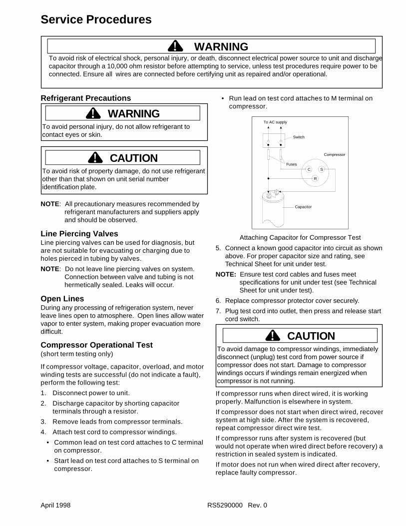
April 1998 RS5290000 Rev. 0
Refrigerant Precautions
WARNING!To avoid personal injury, do not allow refrigerant tocontact eyes or skin.
CAUTION!To avoid risk of property damage, do not use refrigerantother than that shown on unit serial numberidentification plate.
NOTE: All precautionary measures recommended byrefrigerant manufacturers and suppliers applyand should be observed.
Line Piercing ValvesLine piercing valves can be used for diagnosis, butare not suitable for evacuating or charging due toholes pierced in tubing by valves.
NOTE: Do not leave line piercing valves on system.Connection between valve and tubing is nothermetically sealed. Leaks will occur.
Open LinesDuring any processing of refrigeration system, neverleave lines open to atmosphere. Open lines allow watervapor to enter system, making proper evacuation moredifficult.
Compressor Operational Test(short term testing only)
If compressor voltage, capacitor, overload, and motorwinding tests are successful (do not indicate a fault),perform the following test:
1. Disconnect power to unit.
2. Discharge capacitor by shorting capacitorterminals through a resistor.
3. Remove leads from compressor terminals.
4. Attach test cord to compressor windings.
• Common lead on test cord attaches to C terminalon compressor.
• Start lead on test cord attaches to S terminal oncompressor.
Service Procedures
• Run lead on test cord attaches to M terminal oncompressor.
C
R
SFuses
Capacitor
Compressor
Switch
To AC supply
Attaching Capacitor for Compressor Test
5. Connect a known good capacitor into circuit as shownabove. For proper capacitor size and rating, seeTechnical Sheet for unit under test.
NOTE: Ensure test cord cables and fuses meetspecifications for unit under test (see TechnicalSheet for unit under test).
6. Replace compressor protector cover securely.
7. Plug test cord into outlet, then press and release startcord switch.
CAUTION!To avoid damage to compressor windings, immediatelydisconnect (unplug) test cord from power source ifcompressor does not start. Damage to compressorwindings occurs if windings remain energized whencompressor is not running.
If compressor runs when direct wired, it is workingproperly. Malfunction is elsewhere in system.
If compressor does not start when direct wired, recoversystem at high side. After the system is recovered,repeat compressor direct wire test.
If compressor runs after system is recovered (butwould not operate when wired direct before recovery) arestriction in sealed system is indicated.
If motor does not run when wired direct after recovery,replace faulty compressor.
To avoid risk of electrical shock, personal injury, or death, disconnect electrical power source to unit and dischargecapacitor through a 10,000 ohm resistor before attempting to service, unless test procedures require power to beconnected. Ensure all wires are connected before certifying unit as repaired and/or operational.
! WARNING
RS5290000 Rev. 0 April 1998
Dehydrating Sealed Refrigeration SystemMoisture in a refrigerator sealed system exposed toheat generated by the compressor and motor reactschemically with refrigerant and oil in the system andforms corrosive hydrochloric and hydrofluoric acids.These acids contribute to the breakdown of motorwinding insulation and corrosion of compressorworking parts, causing compressor failure.
In addition, sludge, a residue of the chemical reaction,coats all surfaces of sealed system, and will eventuallyrestrict refrigerant flow through capillary tube.
To dehydrate sealed system, evacuate system (seeparagraph Evacuation ).
Leak Testing
DANGER!To prevent serious injury or death from violentexplosions, NEVER use oxygen or acetylene forpressure testing or clean out of refrigeration systems.Free oxygen will explode on contact with oil. Acetylenewill explode spontaneously when put under pressure.
It is important to check sealed system for refrigerantleaks. Undetected leaks can lead to repeated servicecalls and eventually result in system contamination,restrictions, and premature compressor failure.
Refrigerant leaks are best detected with halide orelectronic leak detectors.
Testing Systems Containing a Refrigerant Charge1. Stop the operation (turn refrigerator off).
2. Holding leak detector exploring tube as close tosystem tubing as possible, check all piping, joints,and fittings.
NOTE: Use soap suds on areas leak detector cannotreach or reliably test.
Testing Systems Containing No Refrigerant Charge1. Connect cylinder of nitrogen, through gauge
manifold, to process tube of compressor and liquidline strainer.
2. Open valves on nitrogen cylinder and gagemanifold. Allow pressure to build within sealedsystem.
3. Check for leaks using soap suds.
If a leak is detected in a joint, do not to attempt to repairby applying additional brazing material. Joint must bedisassembled, cleaned and rebrazed. Capture refrigerantcharge (if system is charged), unbraze joint, clean allparts, then rebraze.
If leak is detected in tubing, replace tubing. If leak isdetected in either coil, replace faulty coil.
Service Procedures
! WARNINGTo avoid risk of electrical shock, personal injury, or death, disconnect electrical power source to unit and dischargecapacitor through a resistor before attempting to service, unless test procedures require power to be connected.Ensure all earth wires are connected before certifying unit as repaired and/or operational.
April 1998 RS5290000 Rev. 0
Service Procedures
! WARNINGTo avoid risk of electrical shock, personal injury, or death, disconnect electrical power source to unit and dischargecapacitor through a 10,000 ohm resistor before attempting to service, unless test procedures require power to beconnected. Ensure all earth wires are connected before certifying unit as repaired and/or operational.
RestrictionsSymptomsRestrictions in sealed system most often occur atcapillary tube or filter drier, but can exist anywhere onliquid side of system.
Restrictions reduce refrigerant flow rate and heatremoval rate. Wattage drops because compressor isnot circulating normal amount of refrigerant.
Common causes of total restrictions are moisture,poorly soldered joints, or solid contaminants. Moisturefreezes at evaporator inlet end of capillary tube. Solidcontaminants collect in filter drier.
If restriction is on low side, suction pressure will be in avacuum and head pressure will be near normal
If restriction is on high side, suction pressure will be ina vacuum and head pressure will be higher thannormal during pump out cycle.
Refrigeration occurs on low pressure side of partialrestriction. There will be a temperature difference atthe point of restriction. Frost and/or condensation willbe present in most case at the point of restriction.Also, system requires longer to equalize.
Slight or partial restriction can give the samesymptoms as refrigerant shortage including lower thannormal back pressure, head pressure, wattage, andwarmer temperatures.
Total restriction on the discharge side of compressorwhen restriction is between compressor and first halfof condenser results in higher than normal headpressure and wattage while low side is being pumpedout.
Testing for RestrictionsTo determine if a restriction exists:
1. Attach gauge and manifold between suction anddischarge sides of sealed system.
2. Turn unit on and allow pressure on each side tostabilize. Inspect condenser side of system.Tubing on condenser should be warm andtemperature should be equal throughout (nosudden drops at any point along tubing).
• If temperature of condenser tubing is consistentthroughout, go to step 4.
• If temperature of condenser tubing drops suddenlyat any point, tubing is restricted at point oftemperature drop (if restriction is severe, frost mayform at point of restriction and extend down indirection of refrigerant flow in system). Go to step 5.
3. Visually check system for kinks in refrigeration linewhich is causing restriction. Correct kink andrepeat step 2.
4. Turn unit off and time how long it takes high andlow pressure gauges to equalize:
• If pressure equalization takes longer than 10minutes, a restriction exists in the capillary tube ordrier filter. Go to step 5.
• If pressure equalization takes less than 10 minutes,system is not restricted. Check for other possiblecauses of malfunction.
5. Recover refrigerant in sealed system.
NOTE: Before opening any refrigeration system,capture refrigerant in system for safe disposal.
6. Remove power from unit.
CAUTION!To reduce risk of personal injury or property damage,take necessary precautions against high temperaturesrequired for brazing.
7. Remove and replace restricted device.
8. Evacuate sealed system.
9. Charge system to specification.
NOTE: Do not use captured or recycled refrigerant inAmana units. Captured or recycled refrigerantvoids any Amana and/or compressormanufacturer's warranty.
NOTE: Charge system with exact amount of refrigerant.See Technical Sheet or refer to unit nameplatefor correct refrigerant charge. Inaccuratelycharged system will cause future problems.
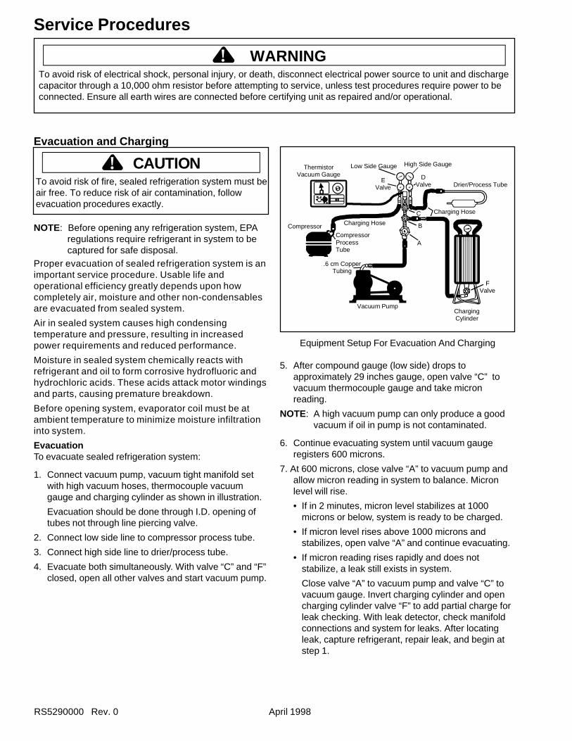
RS5290000 Rev. 0 April 1998
Evacuation and Charging
CAUTION!To avoid risk of fire, sealed refrigeration system must beair free. To reduce risk of air contamination, followevacuation procedures exactly.
NOTE: Before opening any refrigeration system, EPAregulations require refrigerant in system to becaptured for safe disposal.
Proper evacuation of sealed refrigeration system is animportant service procedure. Usable life andoperational efficiency greatly depends upon howcompletely air, moisture and other non-condensablesare evacuated from sealed system.
Air in sealed system causes high condensingtemperature and pressure, resulting in increasedpower requirements and reduced performance.
Moisture in sealed system chemically reacts withrefrigerant and oil to form corrosive hydrofluoric andhydrochloric acids. These acids attack motor windingsand parts, causing premature breakdown.
Before opening system, evaporator coil must be atambient temperature to minimize moisture infiltrationinto system.
EvacuationTo evacuate sealed refrigeration system:
1. Connect vacuum pump, vacuum tight manifold setwith high vacuum hoses, thermocouple vacuumgauge and charging cylinder as shown in illustration.
Evacuation should be done through I.D. opening oftubes not through line piercing valve.
2. Connect low side line to compressor process tube.
3. Connect high side line to drier/process tube.
4. Evacuate both simultaneously. With valve “C” and “F”closed, open all other valves and start vacuum pump.
Vacuum Pump
.6 cm CopperTubing
CompressorCompressorProcessTube
Charging Hose
ThermistorVacuum Gauge
Low Side Gauge
EValve
B
DValve
High Side Gauge
Charging Hose
Drier/Process Tube
FValve
ChargingCylinder
C
A
Equipment Setup For Evacuation And Charging
5. After compound gauge (low side) drops toapproximately 29 inches gauge, open valve “C” tovacuum thermocouple gauge and take micronreading.
NOTE: A high vacuum pump can only produce a goodvacuum if oil in pump is not contaminated.
6. Continue evacuating system until vacuum gaugeregisters 600 microns.
7. At 600 microns, close valve “A” to vacuum pump andallow micron reading in system to balance. Micronlevel will rise.
• If in 2 minutes, micron level stabilizes at 1000microns or below, system is ready to be charged.
• If micron level rises above 1000 microns andstabilizes, open valve “A” and continue evacuating.
• If micron reading rises rapidly and does notstabilize, a leak still exists in system.
Close valve “A” to vacuum pump and valve “C” tovacuum gauge. Invert charging cylinder and opencharging cylinder valve “F” to add partial charge forleak checking. With leak detector, check manifoldconnections and system for leaks. After locatingleak, capture refrigerant, repair leak, and begin atstep 1.
Service Procedures
! WARNINGTo avoid risk of electrical shock, personal injury, or death, disconnect electrical power source to unit and dischargecapacitor through a 10,000 ohm resistor before attempting to service, unless test procedures require power to beconnected. Ensure all earth wires are connected before certifying unit as repaired and/or operational.
April 1998 RS5290000 Rev. 0
ChargingNOTE: Do not use captured or recycled refrigerant in
Amana units. Captured or recycled refrigerantvoids any warranty.
NOTE: Charge system with exact amount of refrigerant.See Technical Sheet or refer to unit serial platefor correct refrigerant charge. Inaccuratelycharged system will cause future problems.
To charge system:
1. Close valves “A” to vacuum pump and “C” to vacuumgauge and “E” to low side manifold gauge.
2. Set scale on dial-a-charge cylinder for correspondingHFC134a pressure reading.
3. Open valve “F” to charging cylinder and let exactamount of refrigerant flow from cylinder into system.Close valve.
Low side gauge pressure should rise shortly afteropening charging cylinder valve as system pressureequalizes through capillary tube.
If pressure does not equalize, a restriction typicallyexists at capillary/drier braze joint.
4. If pressure equalizes, open valve “E” to low sidemanifold gauge and pinch off high side drier processtube.
5. Start compressor and draw remaining refrigerantfrom charging hoses and manifold into compressorthrough compressor process tube.
6. To check high side, pinch-off drier process tube.Close valve “D” to high side gauge. If high sidepressure rises, repeat high side pinch-off and openvalve “D”. Repeat until high side pinch-off does notleak.
7. Pinch-off compressor process tube and removecharging hose. Braze stub closed while compressor isoperating.
8. Disconnect power. Remove charging hose and brazehigh side drier process tube closed.
9. Recheck for refrigerant leaks.
Service Procedures
! WARNINGTo avoid risk of electrical shock, personal injury, or death, disconnect electrical power source to unit and dischargecapacitor through a 10,000 ohm resistor before attempting to service, unless test procedures require power to beconnected. Ensure all earth wires are connected before certifying unit as repaired and/or operational.
Refrigerant ChargeRefrigerant charge in all capillary tube systems iscritical and exact amount is required for properperformance. Factory charges are shown on serialplate. Do not use refrigerant other than shown onserial plate.
RS5290000 Rev. 0 April 1998
To minimize contamination, exercise extremecare when servicing HFC134A sealed systems.
• No trace of other refrigerants is allowed in HFC134asystems. Chlorinated molecules in other refrigerantssuch as CFC12, etc. will lead to capillary tubeplugging.
• Ester oil is used in HFC134a systems. Do not usemineral oil. HFC134a and mineral oils cannot bemixed. If mineral oils were used in HFC134a systems,lubricant would not return to compressor and wouldcause early compressor failure. If significant amountof oil has been lost from compressor, replace oilrather than adding oil.
• Ester oils used in HFC134a systems are sohydroscopic that by the time an inadequate systemperformance is detected, oil will be saturated withmoisture.
• CFC12 has much higher tolerance to systemprocessing materials, such as drawing compounds,rust inhibitors, and cleaning compounds, thanHFC134a. Such materials are not soluble in HFC134asystems. If materials were to be washed from systemsurfaces by ester oils, they could accumulate andeventually plug capillary tube.
• Care must be taken to minimize moisture fromentering HFC134a system. Do not leave compressoror system open to atmosphere for more than 10minutes. Excessive moisture in HFC134a system willreact with compressor oil and generate acid.
• Compressor must be replaced when performing lowside leak repair.
• Drier filter must always be replaced with service drierfilter, part #B2150504.
Important: Unbrazing drier filter from tubing will drivemoisture from desiccant and into system, causingacids to form. Do not unbraze filter drier from tubing.If CFC12 service drier was installed in HFC134Asystem, drier could overload due to excessivemoisture.
• HFC134a compatible copper tubing, part #R0174075and part #R0174076 must be used when replacingtubing.
• Avoid system contamination by using Towerdraw E610evaporating oil, part # R0157532, when flaring,swagging, or cutting refrigeration tubing.
Service Procedures
HFC134a Service InformationHFC134a is alternative refrigerant for CFC12.HFC134a has an ozone depletion potential (ODP)factor of 0.0 and a global warming potential (GWP)factor of 0.27. HFC134a is not flammable and hasacceptable toxicity levels. HFC134a is notinterchangeable with CFC12. There are significantdifferences between HFC134a and CFC12 whichmust be considered when handling and processingrefrigeration system.
Health, Safety, and HandlingHealth, safety and handling considerations forHFC134A are virtually no different than those forCFC12.
Comparison of CFC12 and HFC134a Properties
Caution!
Health, Safety, and Handling CFC12 HFC134aAllowable overall exposure limit 1,000 ppm Same
Vapor exposure to skin No effect SameLiquid exposure to skin Can cause frostbite SameVapor exposure to eye Very slight eye irritant SameLiquid exposure to eye Can cause frostbit SameAbove minimum exposure limit Can cause Asphyxiation,
Tachycardia, and CardiaArrhythmias
Same
Safety and handling Wear appropriate skinand eye protection. Usewith adequateventilation.
Same
Spill management Remove or extinguishignition or combustionsources. Evacuate orventilate area.
Same
Fire explosion hazards May decompose ifcontact with flames andheating elements.Container may explodeif heated due to resultingpressure rise.Combustion productsare toxic.
Same
Disposal procedures Recycle or reclaim. Same
Properties/Characteristics CFC12 HFC134aOzone Depletion Potential (ODP) 1.0* 0.0*Global Warming Potential (GPW) 3.2* 0.27*Molecular weight 121 102Boiling point at 1 atmosphere -22°F (-30°C) -15°F (-
26°C)Vapor pressure at 77°F (25°C) 80 psig 82 psigLiquid density at 77°F (25°C) 82 lb/ft3 75 lb/ft3
Flammability No NoHigh-side system operatingPressure at 65°F (18°C)
HFC134a approximately 3 psighigher than CFC12
Low-side system operatingPressure at 65°F (18°C)
HFC134a approximately 2 psiglower than CFC12
To avoid risk of electrical shock, personal injury, or death, disconnect electrical power source to unit and dischargecapacitor through a 10,000 ohm resistor before attempting to service, unless test procedures require power to beconnected. Ensure all earth wires are connected before certifying unit as repaired and/or operational.
! WARNING
April 1998 RS5290000 Rev. 0
Replacement Service CompressorHFC134a service compressors will be charged withester oil and pressurized with dry nitrogen. Beforereplacement compressor is installed, pull out 1 rubberplug. A pop from pressure release should be heard. Ifa pop sound is not heard, do not use compressor.Positive pressure in compressor is vital to keepmoisture out of ester oil. Do not leave compressoropen to atmosphere for more than 10 minutes.
Compressor Testing Procedures
Refer to “Temperature and Relationship Chart” foroperating watts, test points, and temperature relationshiptest.• Temperature testing is accomplished by using 3 lead
thermocouple temperature tester in specific locations.Test point T-1 is outlet on evaporator coil and T-2 isinlet. Test point T-3 is suction tube temperaturemidway between where armaflex ends and suctionport of compressor (approximately 12 inches fromcompressor).
• Thermocouple tips should be attached securely tospecified locations.
• Do not test during initial pull down. Allow one off cycleor balanced temperature condition to occur beforeproceeding with testing.
• Refrigerator must operate minimum of 20 minutesafter thermocouples are installed.
• Turn control to colder to obtain required on time.• Wattage reading must be recorded in conjunction with
temperature test to confirm proper operation.• Suction and head pressures are listed on
“Temperature and Relationship Chart” Normally theseare not required for diagnosis but used forconfirmation on systems which have been opened.
To avoid death or severe personal injury, never useoxygen, air or acetylene for pressure testing or cleanout of refrigeration system. Use of oxygen, air, oracetylene may result in violent explosion. Oxygen mayexplode on contact with oil and acetylene willspontaneously explode when under pressure.
Service Procedures
To avoid risk of electrical shock, personal injury, or death, disconnect electrical power source to unit and dischargecapacitor through a 10,000 ohm resistor before attempting to service, unless test procedures require power to beconnected. Ensure all earth wires are connected before certifying unit as repaired and/or operational.
! WARNING
Brazing
CAUTION!To reduce risk of personal injury or property damage,take necessary precautions against high temperaturesrequired for brazing.
Satisfactory results require cleanliness, experience,and use of proper materials and equipment.
Connections to be brazed must be properly sized, freeof rough edges, and clean.
Generally accepted brazing materials are:• Copper to copper joints : SIL-FOS (alloy of 15
percent silver, 80 percent copper, and 5 percentphosphorous). Use without flux. Recommendedbrazing temperature is approximately 760°C (1400°F).Do not use for copper to steel connection.
• Copper to steel joints : SILVER SOLDER (alloy of 30percent silver, 38 percent copper, 32 percent zinc).Use with fluoride based flux. Recommended brazingtemperature is approximately 649°C (1200°F).
• Steel to steel joints : SILVER SOLDER (see copperto steel joints).
• Brass to copper joints : SILVER SOLDER (seecopper to steel joints).
• Brass to steel joints : SILVER SOLDER (see copperto steel joints).
Checking Electric Heater Assembly1. Disconnect power to unit.
2. Ensure heater element is cold, then removesuspect heater and visually inspect element forobvious damage (breaks, cracks in element, etc.).
3. Attach ohmmeter to element leads. Check forcontinuity (see tech sheet for unit under test).
If element reads open (infinite or very high resistance):
4. Check disc type thermostat for continuity (see techsheet for open and close values). If open replace.
WARNING!
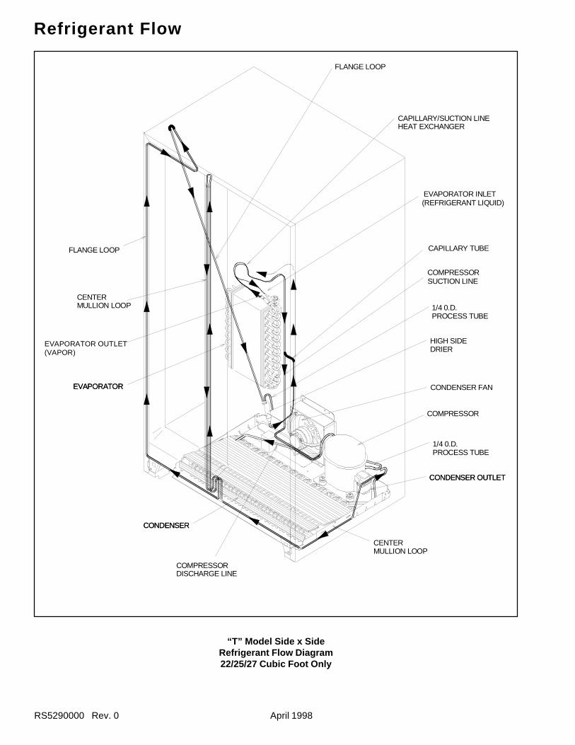
RS5290000 Rev. 0 April 1998
Refrigerant Flow
“T” Model Side x SideRefrigerant Flow Diagram22/25/27 Cubic Foot Only
EVAPORATOR OUTLET(VAPOR)
1/4 0.D.PROCESS TUBE
HIGH SIDEDRIER
COMPRESSOR
CONDENSER FAN
CAPILLARY TUBE
COMPRESSORSUCTION LINE
CONDENSERCONDENSER
COMPRESSORDISCHARGE LINE
CENTERMULLION LOOP
FLANGE LOOP
CENTERMULLION LOOP
FLANGE LOOP
CAPILLARY/SUCTION LINEHEAT EXCHANGER
EVAPORATOREVAPORATOR
EVAPORATOR INLET (REFRIGERANT LIQUID)
1/4 0.D.PROCESS TUBE
CONDENSER OUTLETCONDENSER OUTLET
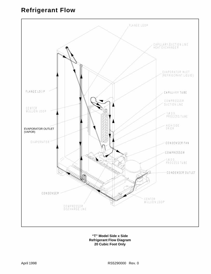
April 1998 RS5290000 Rev. 0
Refrigerant Flow
“T” Model Side x SideRefrigerant Flow Diagram
20 Cubic Foot Only
EVAPORATOR OUTLET(VAPOR)
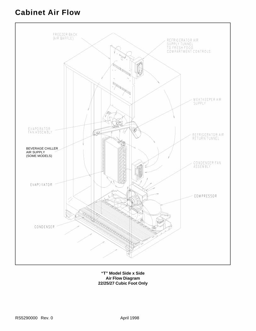
RS5290000 Rev. 0 April 1998
Cabinet Air Flow
BEVERAGE CHILLERAIR SUPPLY(SOME MODELS)
“T” Model Side x SideAir Flow Diagram
22/25/27 Cubic Foot Only
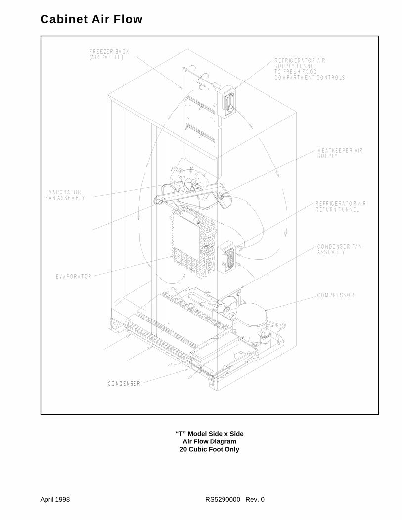
April 1998 RS5290000 Rev. 0
Cabinet Air Flow
“T” Model Side x SideAir Flow Diagram
20 Cubic Foot Only
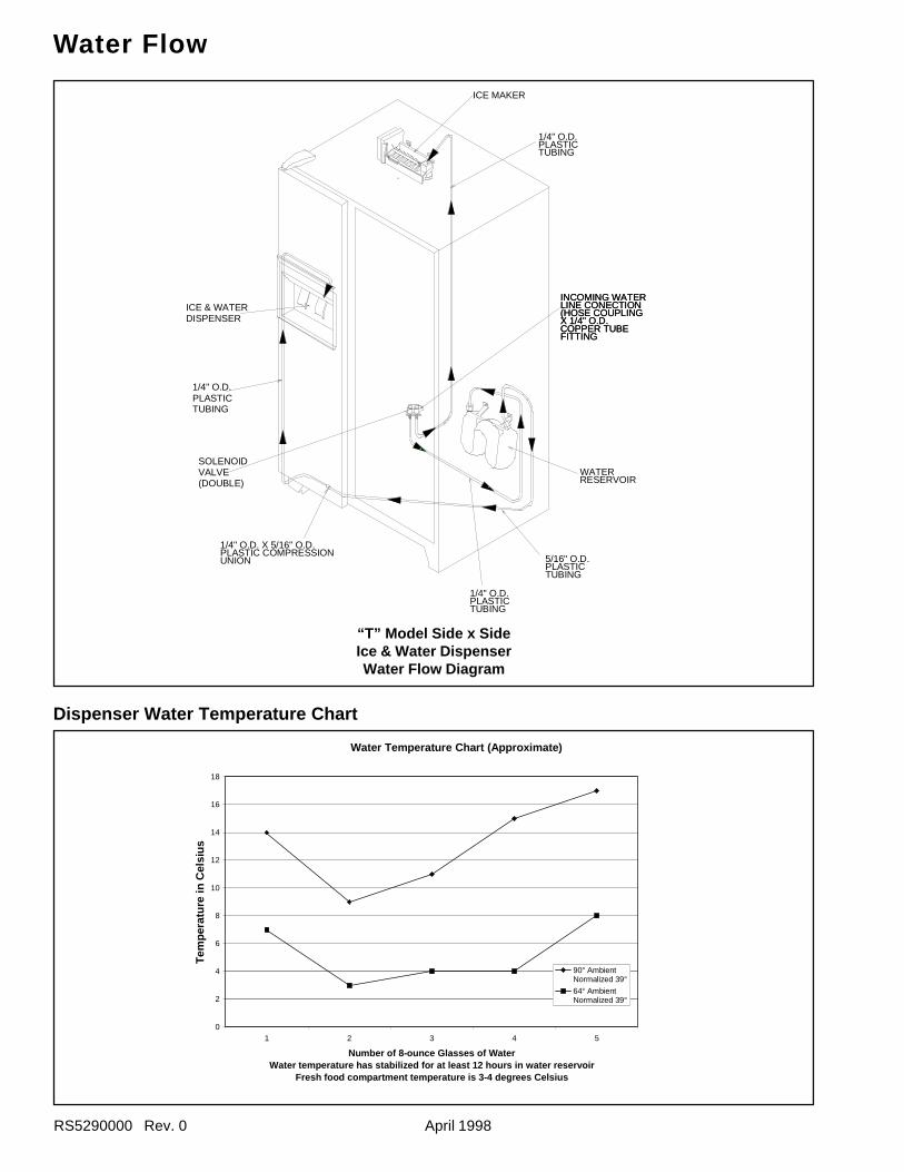
RS5290000 Rev. 0 April 1998
Water Flow
“T” Model Side x SideIce & Water DispenserWater Flow Diagram
Dispenser Water Temperature Chart
Water Temperature Chart (Approximate)
0
2
4
6
8
10
12
14
16
18
1 2 3 4 5
Number of 8-ounce Glasses of WaterWater temperature has stabilized for at least 12 hours in water reservoir
Fresh food compartment temperature is 3-4 degrees Celsius
Tem
pera
ture
in C
elsi
us
90° AmbientNormalized 39°
64° AmbientNormalized 39°
SOLENOIDVALVE(DOUBLE)
1/4" O.D.PLASTICTUBING
ICE & WATERDISPENSER
1/4" O.D. X 5/16" O.D.PLASTIC COMPRESSIONUNION
ICE MAKER
1/4" O.D.PLASTICTUBING
WATERRESERVOIR
5/16" O.D.PLASTICTUBING
INCOMING WATERINCOMING WATERLINE CONECTIONLINE CONECTION(HOSE COUPLING(HOSE COUPLINGX 1/4" O.D.X 1/4" O.D.COPPER TUBECOPPER TUBEFITTINGFITTING
1/4" O.D.PLASTICTUBING
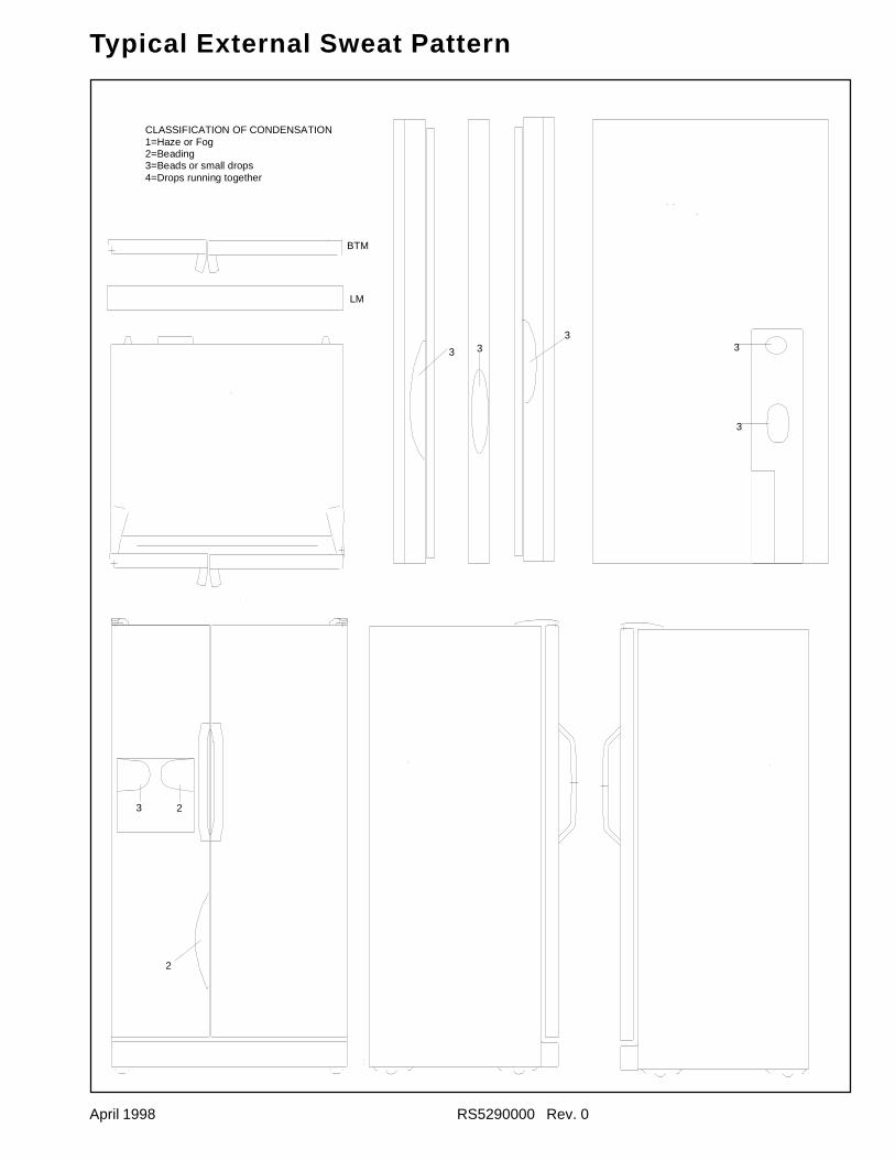
April 1998 RS5290000 Rev. 0
Typical External Sweat Pattern
3
3
3 2
33
3
2
LM
BTM
CLASSIFICATION OF CONDENSATION1=Haze or Fog2=Beading3=Beads or small drops4=Drops running together
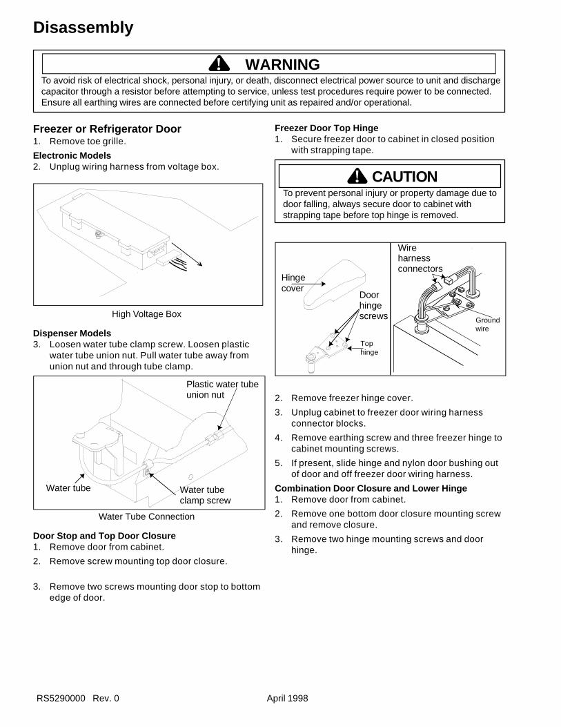
RS5290000 Rev. 0 April 1998
To avoid risk of electrical shock, personal injury, or death, disconnect electrical power source to unit and dischargecapacitor through a resistor before attempting to service, unless test procedures require power to be connected.Ensure all earthing wires are connected before certifying unit as repaired and/or operational.
! WARNING
Disassembly
Freezer or Refrigerator Door1. Remove toe grille.
Electronic Models2. Unplug wiring harness from voltage box.
High Voltage Box
Dispenser Models3. Loosen water tube clamp screw. Loosen plastic
water tube union nut. Pull water tube away fromunion nut and through tube clamp.
Plastic water tubeunion nut
Water tube clamp screw
Water tube
Water Tube Connection
Door Stop and Top Door Closure1. Remove door from cabinet.
2. Remove screw mounting top door closure.
3. Remove two screws mounting door stop to bottomedge of door.
Freezer Door Top Hinge1. Secure freezer door to cabinet in closed position
with strapping tape.
To prevent personal injury or property damage due todoor falling, always secure door to cabinet withstrapping tape before top hinge is removed.
Hingecover
Doorhingescrews
Wireharness connectors
Tophinge
Groundwire
2. Remove freezer hinge cover.
3. Unplug cabinet to freezer door wiring harnessconnector blocks.
4. Remove earthing screw and three freezer hinge tocabinet mounting screws.
5. If present, slide hinge and nylon door bushing outof door and off freezer door wiring harness.
Combination Door Closure and Lower Hinge1. Remove door from cabinet.
2. Remove one bottom door closure mounting screwand remove closure.
3. Remove two hinge mounting screws and doorhinge.
CAUTION!
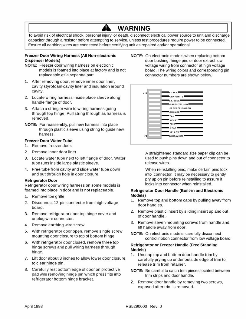
April 1998 RS5290000 Rev. 0
To avoid risk of electrical shock, personal injury, or death, disconnect electrical power source to unit and dischargecapacitor through a resistor before attempting to service, unless test procedures require power to be connected.Ensure all earthing wires are connected before certifying unit as repaired and/or operational.
! WARNING
NOTE: On electronic models when replacing bottomdoor bushing, hinge pin, or door extract lowvoltage wiring from connector at high voltageboard. The wiring colors and corresponding pinconnector numbers are shown below.
#1 2
# 1 B LUE/W HITE
YEL LOW
GRAY
PINK
VIOL ET
T AN
ORAN GE
# 8 SPA CE IS OPE N
G REEN /YEL LOW
L T. BLUE
GRA YWH ITE
B L U E
A straightened standard size paper clip can beused to push pins down and out of connector torelease wires.
When reinstalling pins, make certain pins lockinto connector. It may be necessary to gentlypry up on pin before reinstalling to assure itlocks into connector when reinstalled.
Refrigerator Door Handle (Built-in and ElectronicModels)1. Remove top and bottom caps by pulling away from
door handles.
2. Remove plastic insert by sliding insert up and outof door handle.
3. Remove seven mounting screws from handle andlift handle away from door.
NOTE: On electronic models, carefully disconnectcontrol ribbon connector from low voltage board.
Refrigerator or Freezer Handle (Free StandingModels)1. Unsnap top and bottom door handle trim by
carefully prying up under outside edge of trim torelease trim from retainer.
NOTE: Be careful to catch trim pieces located betweentrim strips and door handle.
2. Remove door handle by removing two screws,exposed after trim is removed.
Freezer Door Wiring Harness (All Non-electronicDispenser Models)NOTE: Freezer door wiring harness on electronic
models is foamed into place at factory and is notreplaceable as a separate part.
1. After removing door, remove inner door liner,cavity styrofoam cavity liner and insulation aroundcavity.
2. Locate wiring harness inside place sleeve alonghandle flange of door.
3. Attach a string or wire to wiring harness goingthrough top hinge. Pull string through as harness isremoved.
NOTE: For reassembly, pull new harness into placethrough plastic sleeve using string to guide newharness.
Freezer Door Water Tube1. Remove freezer door.
2. Remove inner door liner
3. Locate water tube next to left flange of door. Watertube runs inside large plastic sleeve.
4. Free tube from cavity and slide water tube downand out through hole in door closure.
Refrigerator DoorRefrigerator door wiring harness on some models isfoamed into place in door and is not replaceable.
1. Remove toe grille.
2. Disconnect 12-pin connector from high voltageboard.
3. Remove refrigerator door top hinge cover andunplug wire connector.
4. Remove earthing wire screw.
5. With refrigerator door open, remove single screwmounting door closure to top of bottom hinge.
6. With refrigerator door closed, remove three tophinge screws and pull wiring harness throughhinge.
7. Lift door about 3 inches to allow lower door closureto clear hinge pin.
8. Carefully rest bottom edge of door on protectivepad wile removing hinge pin which press fits intorefrigerator bottom hinge bracket.
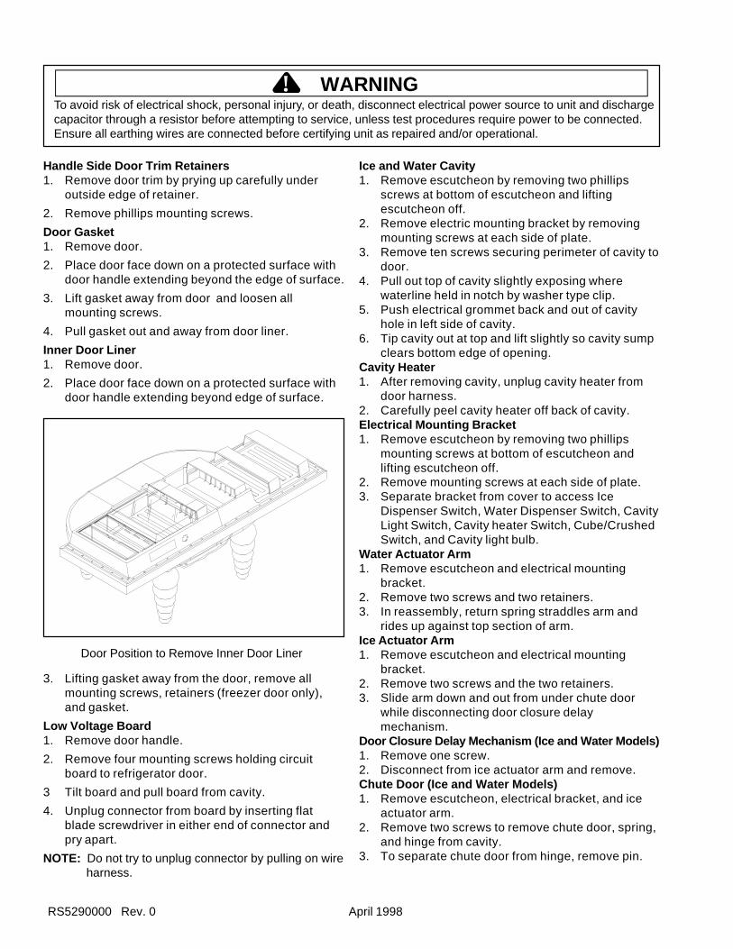
RS5290000 Rev. 0 April 1998
To avoid risk of electrical shock, personal injury, or death, disconnect electrical power source to unit and dischargecapacitor through a resistor before attempting to service, unless test procedures require power to be connected.Ensure all earthing wires are connected before certifying unit as repaired and/or operational.
! WARNING
Handle Side Door Trim Retainers1. Remove door trim by prying up carefully under
outside edge of retainer.
2. Remove phillips mounting screws.
Door Gasket1. Remove door.
2. Place door face down on a protected surface withdoor handle extending beyond the edge of surface.
3. Lift gasket away from door and loosen allmounting screws.
4. Pull gasket out and away from door liner.
Inner Door Liner1. Remove door.
2. Place door face down on a protected surface withdoor handle extending beyond edge of surface.
Door Position to Remove Inner Door Liner
3. Lifting gasket away from the door, remove allmounting screws, retainers (freezer door only),and gasket.
Low Voltage Board1. Remove door handle.
2. Remove four mounting screws holding circuitboard to refrigerator door.
3 Tilt board and pull board from cavity.
4. Unplug connector from board by inserting flatblade screwdriver in either end of connector andpry apart.
NOTE: Do not try to unplug connector by pulling on wireharness.
Ice and Water Cavity1. Remove escutcheon by removing two phillips
screws at bottom of escutcheon and liftingescutcheon off.
2. Remove electric mounting bracket by removingmounting screws at each side of plate.
3. Remove ten screws securing perimeter of cavity todoor.
4. Pull out top of cavity slightly exposing wherewaterline held in notch by washer type clip.
5. Push electrical grommet back and out of cavityhole in left side of cavity.
6. Tip cavity out at top and lift slightly so cavity sumpclears bottom edge of opening.
Cavity Heater1. After removing cavity, unplug cavity heater from
door harness.2. Carefully peel cavity heater off back of cavity.Electrical Mounting Bracket1. Remove escutcheon by removing two phillips
mounting screws at bottom of escutcheon andlifting escutcheon off.
2. Remove mounting screws at each side of plate.3. Separate bracket from cover to access Ice
Dispenser Switch, Water Dispenser Switch, CavityLight Switch, Cavity heater Switch, Cube/CrushedSwitch, and Cavity light bulb.
Water Actuator Arm1. Remove escutcheon and electrical mounting
bracket.2. Remove two screws and two retainers.3. In reassembly, return spring straddles arm and
rides up against top section of arm.Ice Actuator Arm1. Remove escutcheon and electrical mounting
bracket.2. Remove two screws and the two retainers.3. Slide arm down and out from under chute door
while disconnecting door closure delaymechanism.
Door Closure Delay Mechanism (Ice and Water Models)1. Remove one screw.2. Disconnect from ice actuator arm and remove.Chute Door (Ice and Water Models)1. Remove escutcheon, electrical bracket, and ice
actuator arm.2. Remove two screws to remove chute door, spring,
and hinge from cavity.3. To separate chute door from hinge, remove pin.
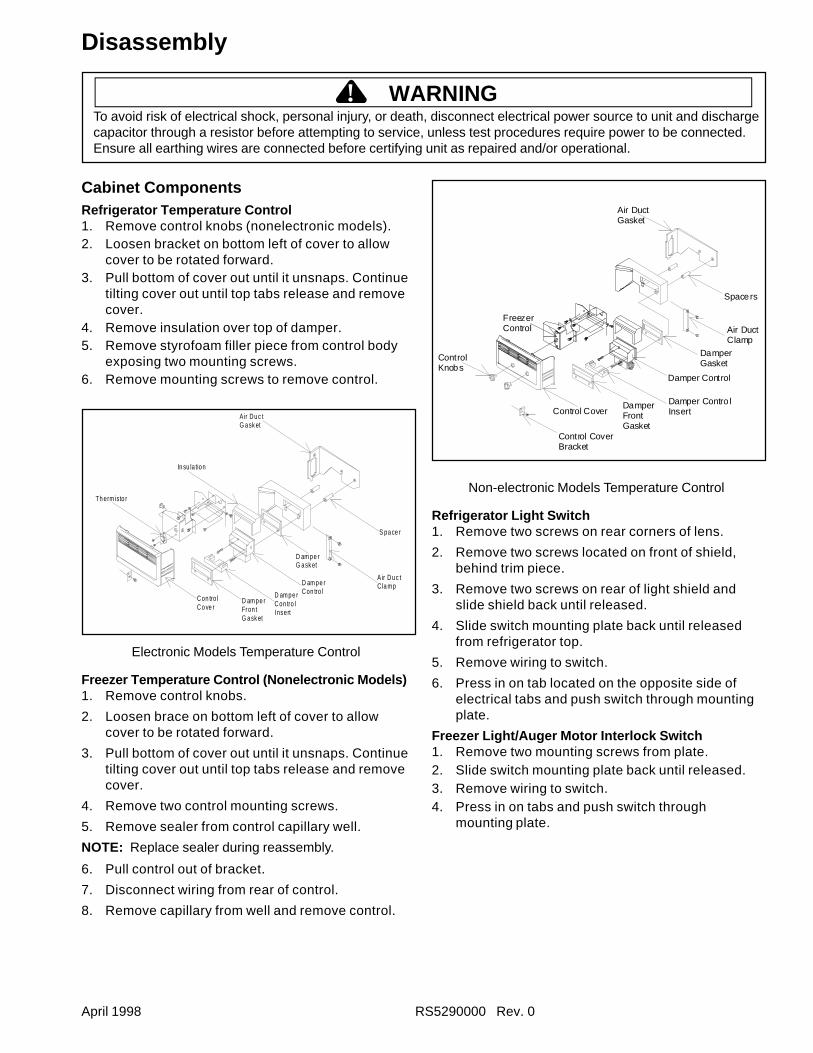
April 1998 RS5290000 Rev. 0
To avoid risk of electrical shock, personal injury, or death, disconnect electrical power source to unit and dischargecapacitor through a resistor before attempting to service, unless test procedures require power to be connected.Ensure all earthing wires are connected before certifying unit as repaired and/or operational.
! WARNING
Cabinet ComponentsRefrigerator Temperature Control1. Remove control knobs (nonelectronic models).2. Loosen bracket on bottom left of cover to allow
cover to be rotated forward.3. Pull bottom of cover out until it unsnaps. Continue
tilting cover out until top tabs release and removecover.
4. Remove insulation over top of damper.5. Remove styrofoam filler piece from control body
exposing two mounting screws.6. Remove mounting screws to remove control.
Th erm isto r
A ir Duc tG ask et
S pa ce r
A ir Duc tC la mp
D am pe rG ask et
In su la tion
D am pe rCon tro lD am pe r
Con tro lInsert
D am pe rFron tG ask et
Con tro lCo ve r
Electronic Models Temperature Control
Freezer Temperature Control (Nonelectronic Models)1. Remove control knobs.
2. Loosen brace on bottom left of cover to allowcover to be rotated forward.
3. Pull bottom of cover out until it unsnaps. Continuetilting cover out until top tabs release and removecover.
4. Remove two control mounting screws.
5. Remove sealer from control capillary well.
NOTE: Replace sealer during reassembly.
6. Pull control out of bracket.
7. Disconnect wiring from rear of control.
8. Remove capillary from well and remove control.
Control Knobs
FreezerControl
Control Cover Bracket
Damper Gasket
Air DuctClamp
Spacers
Air DuctGasket
Control CoverDamper Front Gasket
Damper Contro l Insert
Damper Control
Non-electronic Models Temperature Control
Refrigerator Light Switch1. Remove two screws on rear corners of lens.
2. Remove two screws located on front of shield,behind trim piece.
3. Remove two screws on rear of light shield andslide shield back until released.
4. Slide switch mounting plate back until releasedfrom refrigerator top.
5. Remove wiring to switch.
6. Press in on tab located on the opposite side ofelectrical tabs and push switch through mountingplate.
Freezer Light/Auger Motor Interlock Switch1. Remove two mounting screws from plate.2. Slide switch mounting plate back until released.3. Remove wiring to switch.4. Press in on tabs and push switch through
mounting plate.
Disassembly
RS5290000 Rev. 0 April 1998
To avoid risk of electrical shock, personal injury, or death, disconnect electrical power source to unit and dischargecapacitor through a resistor before attempting to service, unless test procedures require power to be connected.Ensure all earthing wires are connected before certifying unit as repaired and/or operational.
! WARNING
Refrigerator Light Lens and Light Bulbs
CAUTION!To avoid risk of burns, be sure bulb is cool beforeremoving.
1. Remove two mounting bolts on rear corners oflens.
2. Loosen two mounting bolts on front of lens behindtrim piece.
3. Slide lens back until it releases from mountingbolts.
NOTE: Bulbs are standard base screw in type 25 wattappliance bulbs.
Refrigerator Light Socket1. Remove two mounting bolts on rear corners of
lens.
2. Loosen two mounting bolts on front of lens behindtrim piece.
3. Slide lens back until it releases from mountingbolts.
4. Remove wiring to socket.
5. Socket snaps out of shield by pressing on two tabson top and bottom of socket.
Freezer Light Bulb, Light Socket.
CAUTION!To avoid risk of burns, be sure bulb is cool beforeremoving.
1. Remove ice bucket (if applicable).
2. Remove lens top mounting screw and remove lensby lifting up.
NOTE: Bulbs are standard base screw in type 25 wattappliance bulbs.
3. Remove two plate mounting screws from behindfacade and pull facade and mounting plate awayfrom freezer ceiling.
4. Disconnect wiring to socket.
5. Remove socket by pressing on tabs on either sideof socket.
Center MullionCenter mullion is not replaceable.
Disassembly
Freezer Wire Shelf and Shelf Retainers1. Maneuver stops around retainers and pull wire
shelves or baskets out from retainers.
2. Grasp retainer firmly and slide up until released.
Freezer Basket Slide Retainer• Remove two mounting screws and remove
retainer.
EvaporatorFreezer Evaporator Cover1. Remove freezer shelves, freezer basket, ice
service rack, and icemaker.
2. Remove 1/4" hex head mounting screws onevaporator cover.
3. Push ice maker electrical block through opening inpanel. Remove panel.
Freezer Thermistor (Electronic Models)1. Remove eight 1/4” hex head screws retaining
evaporator cover.
2. Remove leads.
3. Remove thermistor by removing 2 screws.
Defrost Thermostat (Terminator)1. Remove eight 1/4” hex head scres retaining
evaporator cover.
2. Unclip thermostat from outlet on evaporator coil.
3. Disconnect leads.
4. Slide clamps from around evaporator tubing andremove thermostat.
Evaporator Defrost Heater1. Remove evaporator cover and thermistor, if
necessary.2. Remove one 1/4" hex head screw from left side of
coil and 2 from right side.3. Remove defrost thermostat.4. Tip bottom of evaporator coil out.
5. Remove 2 wire clips.
6. Slide heater down and out from coil.
7. Unplug heater leads.
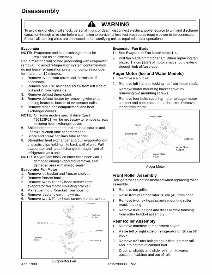
April 1998 RS5290000 Rev. 0
To avoid risk of electrical shock, personal injury, or death, disconnect electrical power source to unit and dischargecapacitor through a resistor before attempting to service, unless test procedures require power to be connected.Ensure all earthing wires are connected before certifying unit as repaired and/or operational.
! WARNING
Disassembly
EvaporatorNOTE: Evaporator and heat exchanger must be
replaced as an assembly.Reclaim refrigerant before proceeding with evaporatorremoval. To avoid refrigeration system contamination,do not leave refrigeration system or compressor openfor more than 10 minutes.1. Remove evaporator cover and thermistor, if
necessary.2. Remove one 1/4" hex head screw from left side of
coil and 2 from right side.3. Remove defrost thermostat.4. Remove defrost heater by removing wire clips
holding heater to bottom of evaporator coils.5. Remove machines compartment and heat
exchanger covers.NOTE: On some models special driver (part
#92113P01) will be necessary to remove screwssecuring heat exchanger cover.
6. Shield interior components from heat source andunbraze suction tube at compressor.
7. Score and break capillary tube at drier.8. Straighten heat exchanger and pull evaporator out
of plastic clips holding it to back wall of unit. Pullevaporator and heat exchanger through front ofrefrigerator as a unit.
NOTE: If styrofoam block on outer case back wall isdamaged during evaporator removal, sealdamaged area with mastic sealer.
Evaporator Fan Motor1. Remove ice bucket and freezer shelves.2. Remove freezer back panel.3. Remove two 5/16" hex head screws from
evaporator fan motor mounting bracket.4. Maneuver motor/bracket from housing.5. Remove lead and earthing wires.6. Remove two 1/4" hex head screws from brackets.
Evaporator Fan
Evaporator Fan Blade1. See Evaporator Fan Motor steps 1-4.
2. Pull fan blade off motor shaft. When replacing fanblade, 1.2 cm (1/2") of motor shaft should extendthrough hub of fan blade.
Auger Motor (Ice and Water Models)1. Remove ice bucket.
2. Remove left-handed locking nut from motor shaft.
3. Remove motor mounting backet cover byremoving two mounting screws.
4. Remove four bolts securing motor to auger motorsupport and back motor out of bracket. Removeleads from motor.
Auger MotorCover
Auger MotorSupport
Capacitor
Auger Motor
Driver
Locking Nut
Auger Motor
Front Roller AssemblyRefrigerator can not be installed when replacing rollerassembly.
1. Remove toe grille
2. Raise front of refrigerator 10 cm (4”) from floor.
3. Remove two hex head screws mounting rollerbrack housing.
4. Remove leveling bolt and disassemble housingfrom roller bracket assembly.
Rear Roller Assembly1. Remove machine compartment cover.
2. Raise left or right side of refrigerator on 10 cm (4”)block.
3. Remove #27 torx bolt going up through rear railand into bottom of cabinet foot.
4. Drop rail slightly and slide roller pin towardsoutside of cabinet and out of rail.
Fa n M o to rB rack et
F a n Grom m et
Fa n B lade
F a n Grom m et
Fa n M o to rB rack et
Fa n M o to r
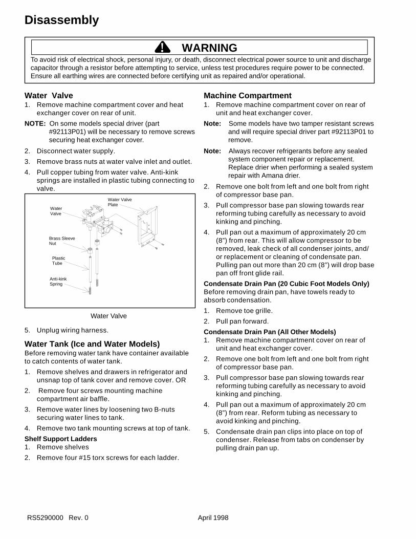
RS5290000 Rev. 0 April 1998
To avoid risk of electrical shock, personal injury, or death, disconnect electrical power source to unit and dischargecapacitor through a resistor before attempting to service, unless test procedures require power to be connected.Ensure all earthing wires are connected before certifying unit as repaired and/or operational.
! WARNING
Disassembly
Water Valve1. Remove machine compartment cover and heat
exchanger cover on rear of unit.
NOTE: On some models special driver (part#92113P01) will be necessary to remove screwssecuring heat exchanger cover.
2. Disconnect water supply.
3. Remove brass nuts at water valve inlet and outlet.
4. Pull copper tubing from water valve. Anti-kinksprings are installed in plastic tubing connecting tovalve.
Water Valve
5. Unplug wiring harness.
Water Tank (Ice and Water Models)Before removing water tank have container availableto catch contents of water tank.
1. Remove shelves and drawers in refrigerator andunsnap top of tank cover and remove cover. OR
2. Remove four screws mounting machinecompartment air baffle.
3. Remove water lines by loosening two B-nutssecuring water lines to tank.
4. Remove two tank mounting screws at top of tank.
Shelf Support Ladders1. Remove shelves
2. Remove four #15 torx screws for each ladder.
Machine Compartment1. Remove machine compartment cover on rear of
unit and heat exchanger cover.
Note: Some models have two tamper resistant screwsand will require special driver part #92113P01 toremove.
Note: Always recover refrigerants before any sealedsystem component repair or replacement.Replace drier when performing a sealed systemrepair with Amana drier.
2. Remove one bolt from left and one bolt from rightof compressor base pan.
3. Pull compressor base pan slowing towards rearreforming tubing carefully as necessary to avoidkinking and pinching.
4. Pull pan out a maximum of approximately 20 cm(8”) from rear. This will allow compressor to beremoved, leak check of all condenser joints, and/or replacement or cleaning of condensate pan.Pulling pan out more than 20 cm (8”) will drop basepan off front glide rail.
Condensate Drain Pan (20 Cubic Foot Models Only)Before removing drain pan, have towels ready toabsorb condensation.
1. Remove toe grille.
2. Pull pan forward.
Condensate Drain Pan (All Other Models)1. Remove machine compartment cover on rear of
unit and heat exchanger cover.
2. Remove one bolt from left and one bolt from rightof compressor base pan.
3. Pull compressor base pan slowing towards rearreforming tubing carefully as necessary to avoidkinking and pinching.
4. Pull pan out a maximum of approximately 20 cm(8”) from rear. Reform tubing as necessary toavoid kinking and pinching.
5. Condensate drain pan clips into place on top ofcondenser. Release from tabs on condenser bypulling drain pan up.
Anti-kinkSpring
Brass SleeveNut
PlasticTube
WaterValve
Water ValvePlate
April 1998 RS5290000 Rev. 0
To avoid risk of electrical shock, personal injury, or death, disconnect electrical power source to unit and dischargecapacitor through a resistor before attempting to service, unless test procedures require power to be connected.Ensure all earthing wires are connected before certifying unit as repaired and/or operational.
! WARNING
Compressor1. See Machine Compartment, Condenser,
Condenser Fan Access.
Note: Always replace drier when repairing refrigerationsystem. Wear eye protection.
2. See Overload and Relay
3. Remove two screws securing condenser fanshroud to outer case back, if necessary.
4. Unclip machine compartment wire harness fromcondenser fan shroud and drier/filter from its metalclip.
5. Capture refrigerant charge.
6. Remove four 7/16" hex head shoulder boltsmounting compressor to machine compartmentfloor.
7. Unbraze suction and discharge tubing fromcompressor.
8. Remove earthing wire screw to compressor.
9. Disconnect electrical leads at overload and relay.
Low Voltage Board1. See Low and High Voltage Board and Showroom
Switch Access.
2. Remove 4 Phillips screws.
3. Disconnect edge connector from right edge ofboard.
4. Take readings at low voltage board.
High Voltage Board1. Remove toe grille.
NOTE: The high voltage board is in the high voltageboard box mounting on the side of condenser on20 cubic foot models and on front of condenseron 27 cubic foot models.
2. Remove the mounting screw holding high voltageboard cover to chassis. Mounting screw on 20cubic foot models is at front of mounting box.Mounting screw on 27 cubic foot models is on rightof mounting box.
3. Slide box foward (20 cubic foot) or to right until boxrear clip disengages from condenser.
4. Pull box out front of unit.
5. Carefully, remove wiring and harness from board.
6. Transfer wiring from old board to replacementboard.
7. Remove mounting screws securing high voltageboard to box.
Power Switch (Electronic Models Only)Power switch at front of high voltage box interruptscircuit to high voltage board.
1. See High Voltage Box.
2. Remove two screws mounting protective flap andswitch to high voltage box.
3. Disconnect leads from switch.
Compressor Run Capacitor (Fan Shroud Mounted)1. Remove compressor compartment rear cover and
heat exchanger cover.
NOTE: On some models special driver (part#92113P01) will be necessary to remove screwssecuring heat exchanger cover.
2. Remove two screws securing condenser fanshroud to out case back.
3. Unclip machines compartment wire harness fromcondenser fan shroud and unclip drier.
4. Remove one bolt from left and one bolt from rightof compressor base pan.
5. Pull compressor base pan slowly towards rearreforming tubing carefully as necessary to avoidkinking and pinching.
6. Pull pan out a maximum of approximately 20 cm(8”) from rear. This will allow compressor to beremoved, leak checking of all condenser joints,and/or replacement or cleaning of condensatepan. Pulling pan out more than 20 cm (8”) will dropbase pan off front glide rail.
7. Disconnect wiring to capacitor.
8. Remove nut securing capacitor to shroud andremove capacitor.
To avoid electrical shock which can cause severepersonal injury or death, discharge capacitor beforehandling.
WARNING
To avoid electrical shock which can cause severepersonal injury or death, discharge capacitor beforehandling.
WARNING
RS5290000 Rev. 0 April 1998
To avoid risk of electrical shock, personal injury, or death, disconnect electrical power source to unit and dischargecapacitor through a resistor before attempting to service, unless test procedures require power to be connected.Ensure all earthing wires are connected before certifying unit as repaired and/or operational.
! WARNING
Compressor Run Capacitor (Control HousingMounted)1. Remove toe grille.
2. Remove mounting screw securing timer/capacitorhousing to condenser.
3. Remove top from housing by removing screwsecuring top to housing.
4. Disconnect wiring to capacitor.
5. Remove nut securing capacitor to housing andremove capacitor.
Overload and Relay1. See Compressor, Condenser, Condenser Fan
Access.2. Remove bale strap from compressor terminal
cover and remove cover.3. Remove electrical leads from overload and relay.4. Pull overload lead off compressor common termal
and pull relay off compressor start and runterminals.
Condenser Fan Blade1. See Compressor, Condenser, Condenser Fan
Access.
2. Remove nut from motor shaft.
3. Remove fan blade. Replace rubber washer behindfan blade when reassembling.
Condenser Fan Motor1. See Condenser Fan Blade
2. Remove compressor electrical cover and removeboth motor leads from overload and relay andearthing wires.
3. Remove three hex head screws mounting motor to
brackets.
Condenser1. See Compressor, Condenser, Condenser Fan
Access.
2. See Condenser Fan Motor, steps 1-3.
Note: Condenser is only available as assembly withbase pan.
Drain Tube1. Remove machine compartment rear cover and heat
exchanger cover.
NOTE: On some models special driver (part#92113P01) will be necessary to remove screwssecuring heat exchanger cover.
2. Remove two screws securing condenser fanshroud out case back, if necessary.
3. Unclip machine compartment wire harness fromcondenser fan shroud. Unclip drier.
4. Remove one bolt from left and one bolt from rightside of compressor compartment pan.
5. Slide compressor compartment out rear of unitapproximately 8 cm (3”).
6. Remove “P” clamps attaching drain tube to theceiling of machine compartment.
7. Pull drain tube off nipple in machine compartmentceiling.
To avoid electrical shock which can cause severepersonal injury or death, discharge capacitor beforehandling.
WARNING
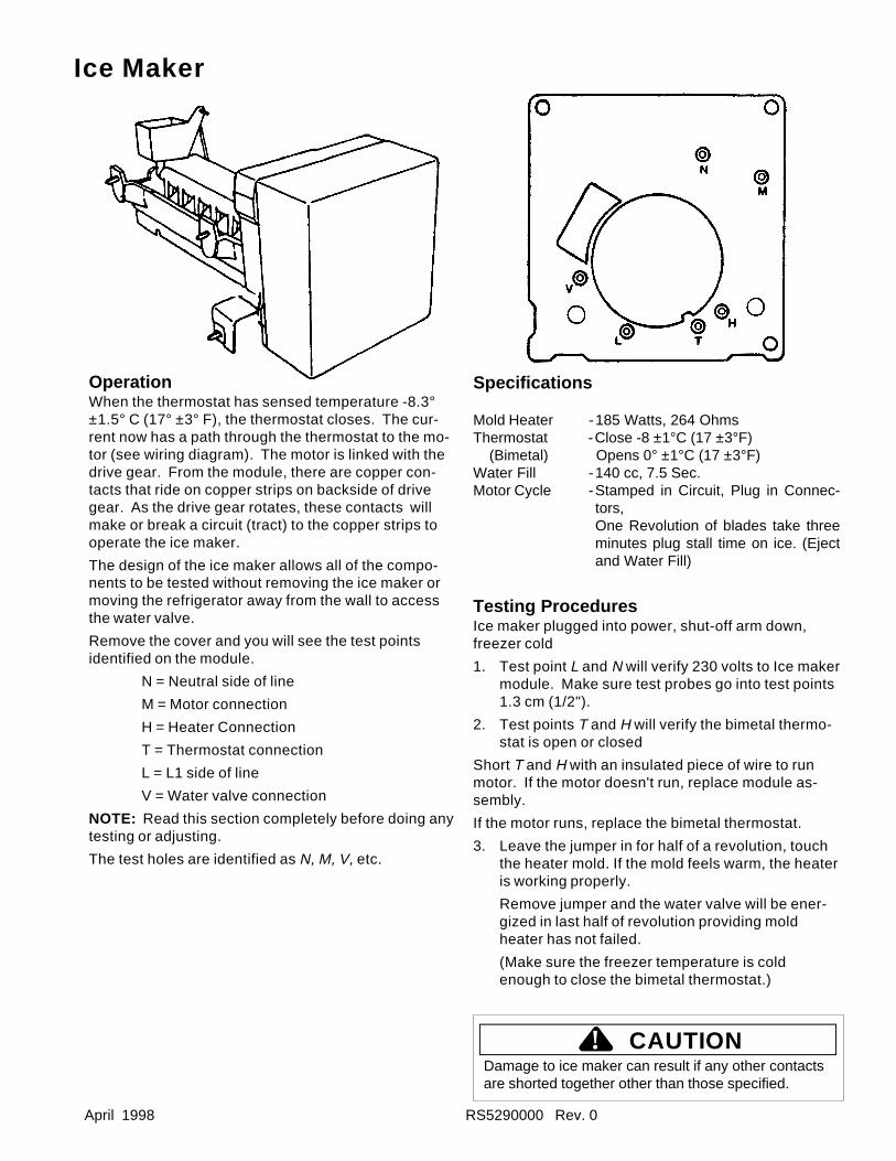
April 1998 RS5290000 Rev. 0
OperationWhen the thermostat has sensed temperature -8.3°±1.5° C (17° ±3° F), the thermostat closes. The cur-rent now has a path through the thermostat to the mo-tor (see wiring diagram). The motor is linked with thedrive gear. From the module, there are copper con-tacts that ride on copper strips on backside of drivegear. As the drive gear rotates, these contacts willmake or break a circuit (tract) to the copper strips tooperate the ice maker.
The design of the ice maker allows all of the compo-nents to be tested without removing the ice maker ormoving the refrigerator away from the wall to accessthe water valve.
Remove the cover and you will see the test pointsidentified on the module.
N = Neutral side of line
M = Motor connection
H = Heater Connection
T = Thermostat connection
L = L1 side of line
V = Water valve connection
NOTE: Read this section completely before doing anytesting or adjusting.
The test holes are identified as N, M, V, etc.
Specifications
Mold Heater -185 Watts, 264 OhmsThermostat -Close -8 ±1°C (17 ±3°F) (Bimetal) Opens 0° ±1°C (17 ±3°F)Water Fill -140 cc, 7.5 Sec.Motor Cycle -Stamped in Circuit, Plug in Connec-
tors,One Revolution of blades take threeminutes plug stall time on ice. (Ejectand Water Fill)
Testing ProceduresIce maker plugged into power, shut-off arm down,freezer cold
1. Test point L and N will verify 230 volts to Ice makermodule. Make sure test probes go into test points1.3 cm (1/2").
2. Test points T and H will verify the bimetal thermo-stat is open or closed
Short T and H with an insulated piece of wire to runmotor. If the motor doesn't run, replace module as-sembly.
If the motor runs, replace the bimetal thermostat.
3. Leave the jumper in for half of a revolution, touchthe heater mold. If the mold feels warm, the heateris working properly.
Remove jumper and the water valve will be ener-gized in last half of revolution providing moldheater has not failed.
(Make sure the freezer temperature is coldenough to close the bimetal thermostat.)
Damage to ice maker can result if any other contactsare shorted together other than those specified.
Ice Maker
CAUTION!
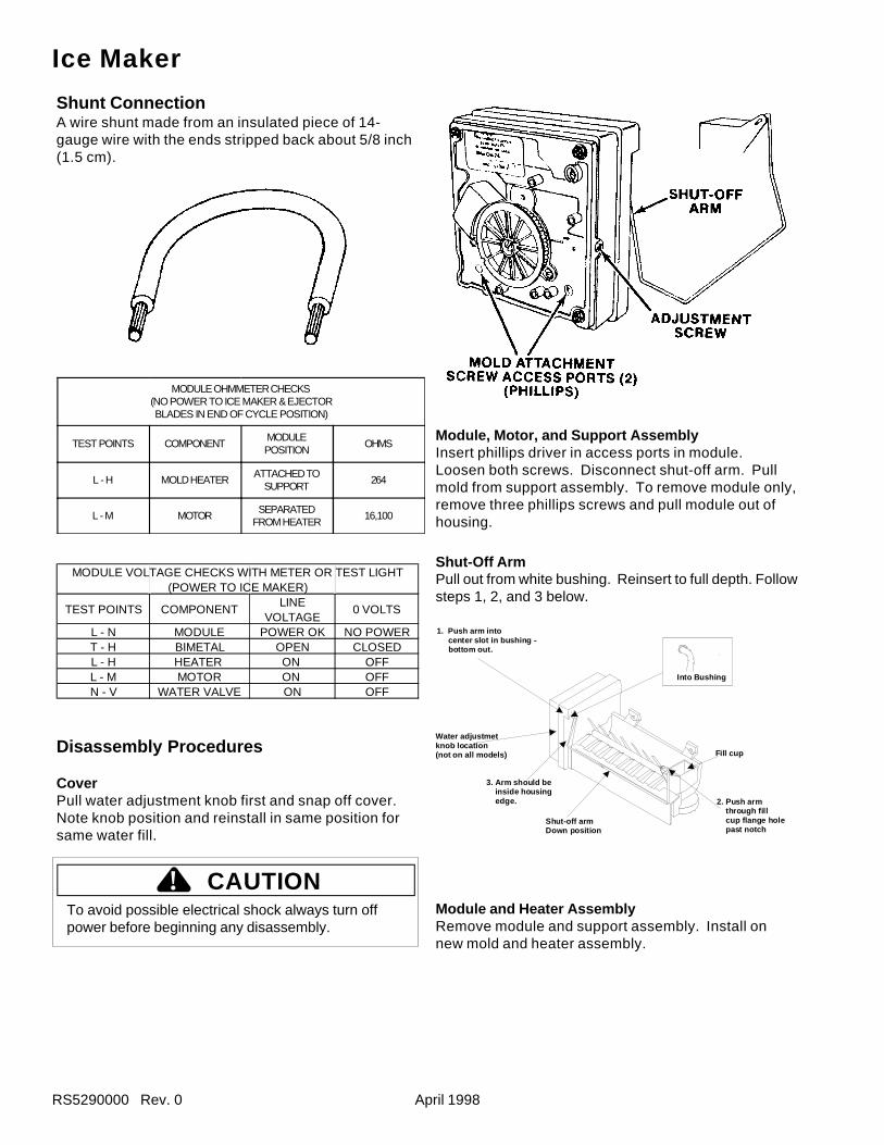
RS5290000 Rev. 0 April 1998
Shunt ConnectionA wire shunt made from an insulated piece of 14-gauge wire with the ends stripped back about 5/8 inch(1.5 cm).
MODULE OHMMETER CHECKS(NO POWER TO ICE MAKER & EJECTORBLADES IN END OF CYCLE POSITION)
TEST POINTS COMPONENTMODULEPOSITION
OHMS
L - H MOLD HEATERATTACHED TO
SUPPORT264
L - M MOTORSEPARATED
FROM HEATER16,100
MODULE VOLT AGE CHE CKS WIT H MET ER OR T ES T LIGHT (POWER T O ICE MAKE R)
T ES T POINT S COMPONENTLINE
VOLT AGE0 VOLT S
L - N MODULE POWER OK NO POWE RT - H BIMET AL OPEN CLOS EDL - H HEAT ER ON OFFL - M MOT OR ON OFFN - V WAT E R VALVE ON OFF
Disassembly Procedures
CoverPull water adjustment knob first and snap off cover.Note knob position and reinstall in same position forsame water fill.
To avoid possible electrical shock always turn offpower before beginning any disassembly.
Module, Motor, and Support AssemblyInsert phillips driver in access ports in module.Loosen both screws. Disconnect shut-off arm. Pullmold from support assembly. To remove module only,remove three phillips screws and pull module out ofhousing.
Shut-Off ArmPull out from white bushing. Reinsert to full depth. Followsteps 1, 2, and 3 below.
Module and Heater AssemblyRemove module and support assembly. Install onnew mold and heater assembly.
Ice Maker
Into Bushing
1. Push arm into center slot in bushing - bottom out.
Water adjustmet knob location (not on all models)
3. Arm should be inside housing edge.
Shut-off armDown position
2. Push arm through fill cup flange hole past notch
Fill cup
CAUTION!
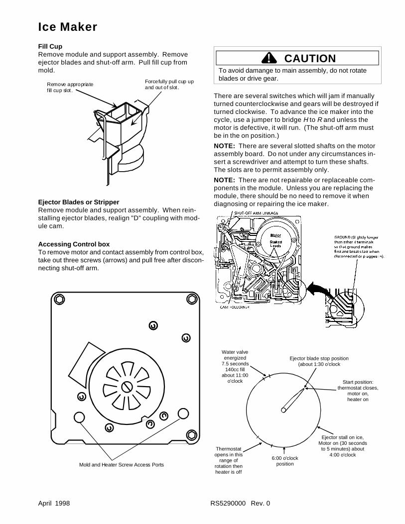
April 1998 RS5290000 Rev. 0
Fill CupRemove module and support assembly. Removeejector blades and shut-off arm. Pull fill cup frommold.
Ejector Blades or StripperRemove module and support assembly. When rein-stalling ejector blades, realign "D" coupling with mod-ule cam.
Accessing Control boxTo remove motor and contact assembly from control box,take out three screws (arrows) and pull free after discon-necting shut-off arm.
To avoid damange to main assembly, do not rotateblades or drive gear.
There are several switches which will jam if manuallyturned counterclockwise and gears will be destroyed ifturned clockwise. To advance the ice maker into thecycle, use a jumper to bridge H to R and unless themotor is defective, it will run. (The shut-off arm mustbe in the on position.)
NOTE: There are several slotted shafts on the motorassembly board. Do not under any circumstances in-sert a screwdriver and attempt to turn these shafts.The slots are to permit assembly only.
NOTE: There are not repairable or replaceable com-ponents in the module. Unless you are replacing themodule, there should be no need to remove it whendiagnosing or repairing the ice maker.
Water valveenergized
7.5 seconds140cc fill
about 11:00o'clock
Ejector blade stop position(about 1:30 o'clock
Start position: thermostat closes,
motor on, heater on
Ejector stall on ice,Motor on (30 secondsto 5 minutes) about
4:00 o'clock6:00 o'clock
position
Thermostatopens in this
range of rotation thenheater is off
Ice Maker
CAUTION!
Remove appropriate fill cup slot .
Forcefully pull cup up and out of slot .
Mold and Heater Screw Access Ports
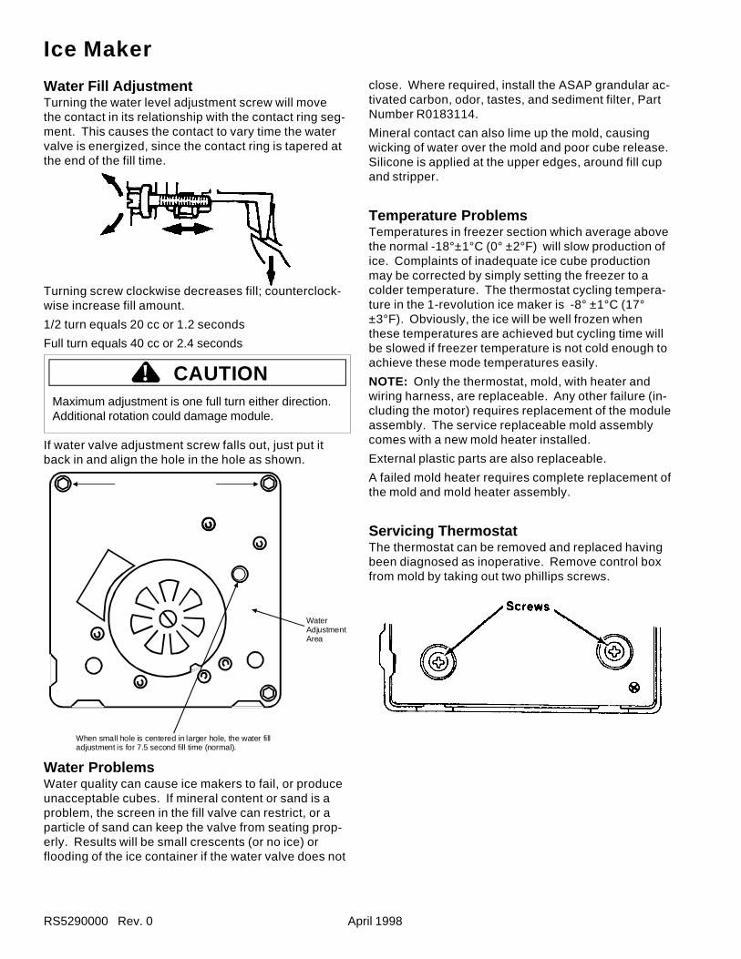
RS5290000 Rev. 0 April 1998
Water Fill AdjustmentTurning the water level adjustment screw will movethe contact in its relationship with the contact ring seg-ment. This causes the contact to vary time the watervalve is energized, since the contact ring is tapered atthe end of the fill time.
Turning screw clockwise decreases fill; counterclock-wise increase fill amount.
1/2 turn equals 20 cc or 1.2 seconds
Full turn equals 40 cc or 2.4 seconds
Maximum adjustment is one full turn either direction.Additional rotation could damage module.
If water valve adjustment screw falls out, just put itback in and align the hole in the hole as shown.
Water ProblemsWater quality can cause ice makers to fail, or produceunacceptable cubes. If mineral content or sand is aproblem, the screen in the fill valve can restrict, or aparticle of sand can keep the valve from seating prop-erly. Results will be small crescents (or no ice) orflooding of the ice container if the water valve does not
close. Where required, install the ASAP grandular ac-tivated carbon, odor, tastes, and sediment filter, PartNumber R0183114.
Mineral contact can also lime up the mold, causingwicking of water over the mold and poor cube release.Silicone is applied at the upper edges, around fill cupand stripper.
Temperature ProblemsTemperatures in freezer section which average abovethe normal -18°±1°C (0° ±2°F) will slow production ofice. Complaints of inadequate ice cube productionmay be corrected by simply setting the freezer to acolder temperature. The thermostat cycling tempera-ture in the 1-revolution ice maker is -8° ±1°C (17°±3°F). Obviously, the ice will be well frozen whenthese temperatures are achieved but cycling time willbe slowed if freezer temperature is not cold enough toachieve these mode temperatures easily.
NOTE: Only the thermostat, mold, with heater andwiring harness, are replaceable. Any other failure (in-cluding the motor) requires replacement of the moduleassembly. The service replaceable mold assemblycomes with a new mold heater installed.
External plastic parts are also replaceable.
A failed mold heater requires complete replacement ofthe mold and mold heater assembly.
Servicing ThermostatThe thermostat can be removed and replaced havingbeen diagnosed as inoperative. Remove control boxfrom mold by taking out two phillips screws.
Ice Maker
CAUTION!
When small hole is centered in larger hole, the water filladjustment is for 7.5 second fill time (normal).
WaterAdjustmentArea
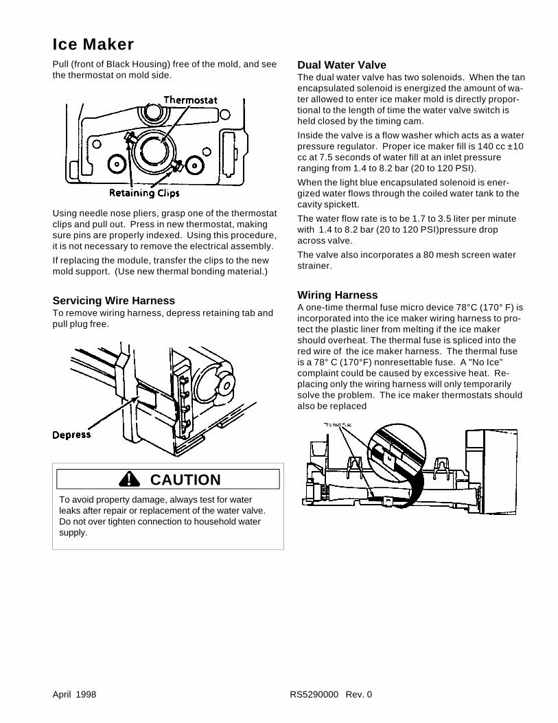
April 1998 RS5290000 Rev. 0
Ice MakerPull (front of Black Housing) free of the mold, and seethe thermostat on mold side.
Using needle nose pliers, grasp one of the thermostatclips and pull out. Press in new thermostat, makingsure pins are properly indexed. Using this procedure,it is not necessary to remove the electrical assembly.
If replacing the module, transfer the clips to the newmold support. (Use new thermal bonding material.)
Servicing Wire HarnessTo remove wiring harness, depress retaining tab andpull plug free.
To avoid property damage, always test for waterleaks after repair or replacement of the water valve.Do not over tighten connection to household watersupply.
Dual Water ValveThe dual water valve has two solenoids. When the tanencapsulated solenoid is energized the amount of wa-ter allowed to enter ice maker mold is directly propor-tional to the length of time the water valve switch isheld closed by the timing cam.
Inside the valve is a flow washer which acts as a waterpressure regulator. Proper ice maker fill is 140 cc ±10cc at 7.5 seconds of water fill at an inlet pressureranging from 1.4 to 8.2 bar (20 to 120 PSI).
When the light blue encapsulated solenoid is ener-gized water flows through the coiled water tank to thecavity spickett.
The water flow rate is to be 1.7 to 3.5 liter per minutewith 1.4 to 8.2 bar (20 to 120 PSI)pressure dropacross valve.
The valve also incorporates a 80 mesh screen waterstrainer.
Wiring HarnessA one-time thermal fuse micro device 78°C (170° F) isincorporated into the ice maker wiring harness to pro-tect the plastic liner from melting if the ice makershould overheat. The thermal fuse is spliced into thered wire of the ice maker harness. The thermal fuseis a 78° C (170°F) nonresettable fuse. A "No Ice"complaint could be caused by excessive heat. Re-placing only the wiring harness will only temporarilysolve the problem. The ice maker thermostats shouldalso be replaced
CAUTION!
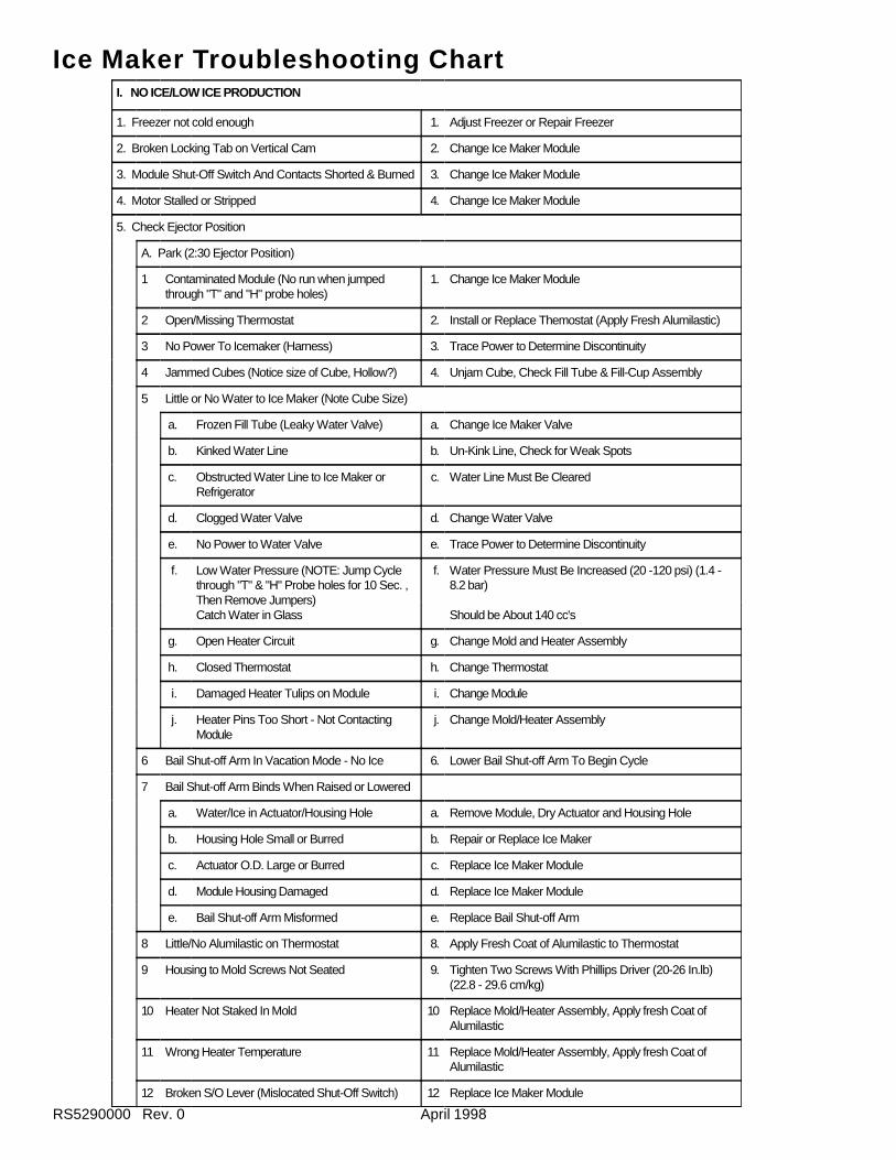
RS5290000 Rev. 0 April 1998
I. NO ICE/LOW ICE PRODUCTION
1. Freezer not cold enough 1. Adjust Freezer or Repair Freezer
2. Broken Locking Tab on Vertical Cam 2. Change Ice Maker Module
3. Module Shut-Off Switch And Contacts Shorted & Burned 3. Change Ice Maker Module
4. Motor Stalled or Stripped 4. Change Ice Maker Module
5. Check Ejector Position
A. Park (2:30 Ejector Position)
1 Contaminated Module (No run when jumpedthrough "T" and "H" probe holes)
1. Change Ice Maker Module
2 Open/Missing Thermostat 2. Install or Replace Themostat (Apply Fresh Alumilastic)
3 No Power To Icemaker (Harness) 3. Trace Power to Determine Discontinuity
4 Jammed Cubes (Notice size of Cube, Hollow?) 4. Unjam Cube, Check Fill Tube & Fill-Cup Assembly
5 Little or No Water to Ice Maker (Note Cube Size)
a. Frozen Fill Tube (Leaky Water Valve) a. Change Ice Maker Valve
b. Kinked Water Line b. Un-Kink Line, Check for Weak Spots
c. Obstructed Water Line to Ice Maker orRefrigerator
c. Water Line Must Be Cleared
d. Clogged Water Valve d. Change Water Valve
e. No Power to Water Valve e. Trace Power to Determine Discontinuity
f. Low Water Pressure (NOTE: Jump Cyclethrough "T" & "H" Probe holes for 10 Sec. ,Then Remove Jumpers)Catch Water in Glass
f. Water Pressure Must Be Increased (20 -120 psi) (1.4 -8.2 bar)
Should be About 140 cc's
g. Open Heater Circuit g. Change Mold and Heater Assembly
h. Closed Thermostat h. Change Thermostat
i. Damaged Heater Tulips on Module i. Change Module
j. Heater Pins Too Short - Not ContactingModule
j. Change Mold/Heater Assembly
6 Bail Shut-off Arm In Vacation Mode - No Ice 6. Lower Bail Shut-off Arm To Begin Cycle
7 Bail Shut-off Arm Binds When Raised or Lowered
a. Water/Ice in Actuator/Housing Hole a. Remove Module, Dry Actuator and Housing Hole
b. Housing Hole Small or Burred b. Repair or Replace Ice Maker
c. Actuator O.D. Large or Burred c. Replace Ice Maker Module
d. Module Housing Damaged d. Replace Ice Maker Module
e. Bail Shut-off Arm Misformed e. Replace Bail Shut-off Arm
8 Little/No Alumilastic on Thermostat 8. Apply Fresh Coat of Alumilastic to Thermostat
9 Housing to Mold Screws Not Seated 9. Tighten Two Screws With Phillips Driver (20-26 In.lb)(22.8 - 29.6 cm/kg)
10 Heater Not Staked In Mold 10 Replace Mold/Heater Assembly, Apply fresh Coat ofAlumilastic
11 Wrong Heater Temperature 11 Replace Mold/Heater Assembly, Apply fresh Coat ofAlumilastic
12 Broken S/O Lever (Mislocated Shut-Off Switch) 12 Replace Ice Maker Module
Ice Maker Troubleshooting Chart
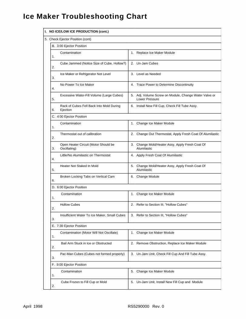
April 1998 RS5290000 Rev. 0
I. NO ICE/LOW ICE PRODUCTION (cont.)
5. Check Ejector Position (cont)
B. 3:00 Ejector Position
1.Contamination 1. Replace Ice Maker Module
2.Cube Jammed (Notice Size of Cube, Hollow?) 2. Un-Jam Cubes
3.Ice Maker or Refrigerator Not Level 3. Level as Needed
4.No Power To Ice Maker 4. Trace Power to Determine Discontinuity
5.Excessive Water-Fill Volume (Large Cubes) 5. Adj. Volume Screw on Module, Change Water Valve or
Lower Pressure
6.Rack of Cubes Fell Back Into Mold DuringEjection
6. Install New Fill Cup, Check Fill Tube Assy.
C. 4:00 Ejector Position
1.Contamination 1. Change Ice Maker Module
2.Thermostat out of calibration 2. Change Out Thermostat, Apply Fresh Coat Of Alumilastic
3.Open Heater Circuit (Motor Should beOscillating)
3. Change Mold/Heater Assy, Apply Fresh Coat OfAlumilastic
4.Little/No Alumilastic on Thermostat 4. Apply Fresh Coat Of Alumilastic
5.Heater Not Staked In Mold 5. Change Mold/Heater Assy, Apply Fresh Coat Of
Alumilastic
6.Broken Locking Tabs on Vertical Cam 6. Change Module
D. 6:00 Ejector Position
1. Contamination 1. Change Ice Maker Module
2.Hollow Cubes 2. Refer to Section III, "Hollow Cubes"
3.Insufficient Water To Ice Maker, Small Cubes 3. Refer to Section III, "Hollow Cubes"
E. 7:30 Ejector Position
1.Contamination (Motor Will Not Oscillate) 1. Change Ice Maker Module
2. Bail Arm Stuck in Ice or Obstructed 2. Remove Obstruction, Replace Ice Maker Module
3.Pac-Man Cubes (Cubes not formed properly) 3. Un-Jam Unit, Check Fill Cup And Fill Tube Assy.
F. 9:00 Ejector Position
1. Contamination 5. Change Ice Maker Module
2. Cube Frozen to Fill Cup or Mold 5. Un-Jam Unit, Install New Fill Cup and Module
Ice Maker Troubleshooting Chart
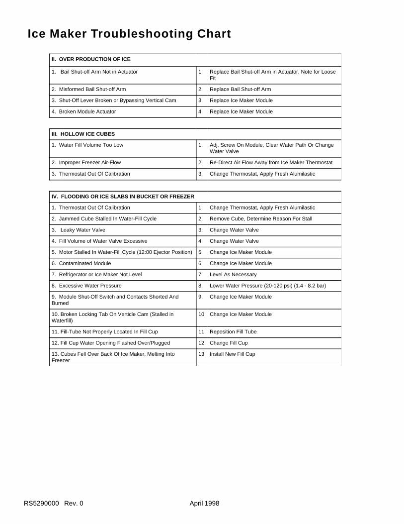
RS5290000 Rev. 0 April 1998
II. OVER PRODUCTION OF ICE
1. Bail Shut-off Arm Not in Actuator 1. Replace Bail Shut-off Arm in Actuator, Note for LooseFit
2. Misformed Bail Shut-off Arm 2. Replace Bail Shut-off Arm
3. Shut-Off Lever Broken or Bypassing Vertical Cam 3. Replace Ice Maker Module
4. Broken Module Actuator 4. Replace Ice Maker Module
III. HOLLOW ICE CUBES
1. Water Fill Volume Too Low 1. Adj. Screw On Module, Clear Water Path Or ChangeWater Valve
2. Improper Freezer Air-Flow 2. Re-Direct Air Flow Away from Ice Maker Thermostat
3. Thermostat Out Of Calibration 3. Change Thermostat, Apply Fresh Alumilastic
IV. FLOODING OR ICE SLABS IN BUCKET OR FREEZER
1. Thermostat Out Of Calibration 1. Change Thermostat, Apply Fresh Alumilastic
2. Jammed Cube Stalled In Water-Fill Cycle 2. Remove Cube, Determine Reason For Stall
3. Leaky Water Valve 3. Change Water Valve
4. Fill Volume of Water Valve Excessive 4. Change Water Valve
5. Motor Stalled In Water-Fill Cycle (12:00 Ejector Position) 5. Change Ice Maker Module
6. Contaminated Module 6. Change Ice Maker Module
7. Refrigerator or Ice Maker Not Level 7. Level As Necessary
8. Excessive Water Pressure 8. Lower Water Pressure (20-120 psi) (1.4 - 8.2 bar)
9. Module Shut-Off Switch and Contacts Shorted AndBurned
9. Change Ice Maker Module
10. Broken Locking Tab On Verticle Cam (Stalled inWaterfill)
10 Change Ice Maker Module
11. Fill-Tube Not Properly Located In Fill Cup 11 Reposition Fill Tube
12. Fill Cup Water Opening Flashed Over/Plugged 12 Change Fill Cup
13. Cubes Fell Over Back Of Ice Maker, Melting IntoFreezer
13 Install New Fill Cup
Ice Maker Troubleshooting Chart
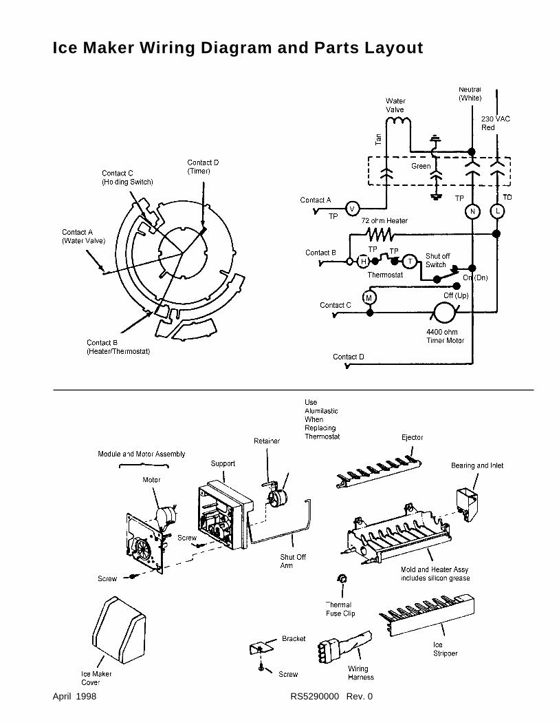
April 1998 RS5290000 Rev. 0
Ice Maker Wiring Diagram and Parts Layout
230
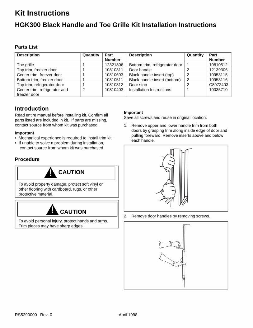
RS5290000 Rev. 0 April 1998
Kit Instructions
IntroductionRead entire manual before installing kit. Confirm allparts listed are included in kit. If parts are missing,contact source from whom kit was purchased.
Important• Mechanical experience is required to install trim kit.• If unable to solve a problem during installation,
contact source from whom kit was purchased.
Procedure
! CAUTION
To avoid property damage, protect soft vinyl orother flooring with cardboard, rugs, or otherprotective material.
CAUTIONTo avoid personal injury, protect hands and arms.Trim pieces may have sharp edges.
2. Remove door handles by removing screws.
Description Quantity PartNumber
Description Quantity PartNumber
Toe grille 1 12321806 Bottom trim, refrigerator door 1 10810512Top trim, freezer door 1 10810311 Door handle 2 12139306Center trim, freezer door 1 10810603 Black handle insert (top) 2 10953115Bottom trim, freezer door 1 10810511 Black handle insert (bottom) 2 10953116Top trim, refrigerator door 1 10810312 Door stop 2 C8972403Center trim, refrigerator andfreezer door
2 10810403 Installation Instructions 1 10035710
Parts List
HGK300 Black Handle and Toe Grille Kit Installation Instructions
!
ImportantSave all screws and reuse in original location.
1. Remove upper and lower handle trim from bothdoors by grasping trim along inside edge of door andpulling foreward. Remove inserts above and beloweach handle.
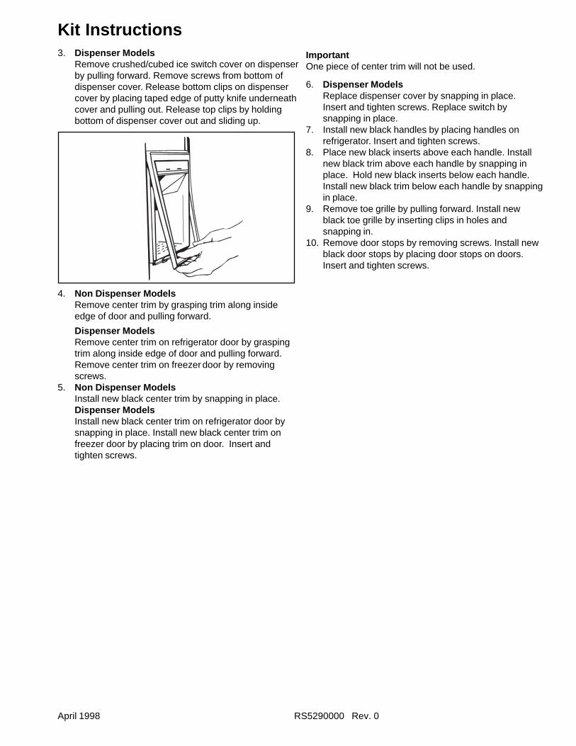
April 1998 RS5290000 Rev. 0
Kit Instructions3. Dispenser Models
Remove crushed/cubed ice switch cover on dispenserby pulling forward. Remove screws from bottom ofdispenser cover. Release bottom clips on dispensercover by placing taped edge of putty knife underneathcover and pulling out. Release top clips by holdingbottom of dispenser cover out and sliding up.
4. Non Dispenser ModelsRemove center trim by grasping trim along insideedge of door and pulling forward.
Dispenser ModelsRemove center trim on refrigerator door by graspingtrim along inside edge of door and pulling forward.Remove center trim on freezer door by removingscrews.
5. Non Dispenser ModelsInstall new black center trim by snapping in place.Dispenser ModelsInstall new black center trim on refrigerator door bysnapping in place. Install new black center trim onfreezer door by placing trim on door. Insert andtighten screws.
ImportantOne piece of center trim will not be used.
6. Dispenser ModelsReplace dispenser cover by snapping in place.Insert and tighten screws. Replace switch bysnapping in place.
7. Install new black handles by placing handles onrefrigerator. Insert and tighten screws.
8. Place new black inserts above each handle. Installnew black trim above each handle by snapping inplace. Hold new black inserts below each handle.Install new black trim below each handle by snappingin place.
9. Remove toe grille by pulling forward. Install newblack toe grille by inserting clips in holes andsnapping in.
10. Remove door stops by removing screws. Install newblack door stops by placing door stops on doors.Insert and tighten screws.
RS5290000 Rev. 0 April 1998
Kit Instructions
DS18 and DS22 1/4" Trim KitsIntroduction
Included in this kit are trim pieces for installing 1/4 inch(6 millimeter) decorator panels. Read entire manualbefore installing panels. Confirm all parts listed areincluded in kit. If parts are missing, contact source fromwhom kit was purchased.
Important• Mechanical experience is required to install trim kit.• Depending on installer’s knowledge and skill,
installation can take from one to three hours.• Transfer food to an alternate cooling source. Check
refrigerator warranty certificate for specificcoverage. Warranty does not cover food loss.
• Ensure trim pieces adhere properly by confirmingsurfaces are clean, dry and free of adhesiveresidue.
• If unable to solve a problem during installation,contact source from whom kit was purchased.
Decorator Panel Dimensions
Listed below are required height x width dimensions fordecorator panels. Panels are not supplied with this kitand can be purchased locally.
CautionTo avoid personal injury or property damage,refrigerator panels should not weigh more than 30pounds (14 kilograms) and freezer panels should notweigh more than 15 pounds (7 kilograms).
19 cubic foot Panel DimensionsWithout DispenserRefrigerator Door 61 15/16" x 15 13/32"
(1573 mm x 391 mm)Freezer Door 61 15/16" x 13 1/2"
(1573 mm x 343 mm)
With DispenserRefrigerator Door 61 15/16" x 15 13/32"
(1573 mm x 391 mm)Upper Freezer Door 17 1/4" x 13 1/2"
(438 mm x 343 mm)Lower Freezer Door 31 13/16" x 13 1/2"
(808 mm x 343 mm)
20, 22, 25 cubic foot Panel DimensionsWithout DispenserRefrigerator Door 61 15/16" x 19 5/32"
(1573 mm x 487 mm)Freezer Door 61 15/16" x 13 1/2"
(1573 mm x 343 mm)
With DispenserRefrigerator Door 61 15/16" x 19 5/32"
(1573 mm x 487 mm)Upper Freezer Door 17 1/4" x 13 1/2"
(438 mm x 343 mm)Lower Freezer Door 31 13/16" x 13 1/2"
(808 mm x 343 mm)
April 1998 RS5290000 Rev. 0
Kit Instructions
Parts List
Item Description Qty LengthDS18EBlack
DS18LAlmond
DS18SSatin
DS18WWhite
DS22EBlack
DS22SSatin
1 Side Trim, Refrigeratorand Freezer Door 2 X X X X X X
2 Bottom Trim,Refrigerator Door 1 X X X X X X
3 Bottom Trim,Freezer Door 1 X X X X X X
4 Top Trim,Refrigerator Door 1 X X X X X X
5 Top Trim, Freezer Door 1 X X X X X X
6 Top Trim, Dispenser 1 13 7/8" X X X X X X
7 Bottom Trim, Dispenser 1 13 9/16" X X X X X X
8Panel Trim, Refrigeratorand Freezer Door
2 61 29/32" X X X X X X
9 Panel Trim, Lower Iceand Water FreezerDoor 1 32 1/8" X X X X X X
10 Panel Trim, Upper Iceand Water FreezerDoor 1 17 7/32" X X X X X X
11 Screw, Bottom Trim 5 X X X X X X
12 Spacer, RefrigeratorDoor Bottom Trim 1 X X X X X X
13 Spacer, Freezer DoorBottom Trim 1 X X X X X X
14 Installation Instructions 1 X X X X X X
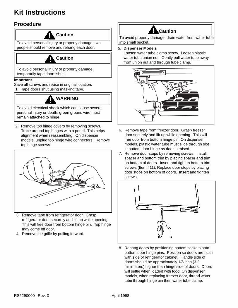
RS5290000 Rev. 0 April 1998
Kit Instructions
Procedure
Caution
To avoid personal injury or property damage, twopeople should remove and rehang each door.
Caution
To avoid personal injury or property damage,temporarily tape doors shut.
ImportantSave all screws and reuse in original location.1. Tape doors shut using masking tape.
WARNING
To avoid electrical shock which can cause severepersonal injury or death, green ground wire mustremain attached to hinge.
2. Remove top hinge covers by removing screws.Trace around top hinges with a pencil. This helpsalignment when reassembling. On dispensermodels, unplug top hinge wire connectors. Removetop hinge screws.
CautionTo avoid property damage, drain water from water tubeinto small bucket.
5. Dispenser ModelsLoosen water tube clamp screw. Loosen plasticwater tube union nut. Gently pull water tube awayfrom union nut and through tube clamp.
6. Remove tape from freezer door. Grasp freezerdoor securely and lift up while opening. This willfree door from bottom hinge pin. On dispensermodels, plastic water tube must slide through slotin bottom door hinge as door is raised.
7. Remove door stops by removing screws. Installspacer and bottom trim by placing spacer and trimon bottom of doors. Insert and tighten bottom trimscrews (Item #11). Replace door stops by placingdoor stops on bottom of doors. Insert and tightenscrews.
3. Remove tape from refrigerator door. Grasprefrigerator door securely and lift up while opening.This will free door from bottom hinge pin. Top hingemay come off door.
4. Remove toe grille by pulling forward.
8. Rehang doors by positioning bottom sockets ontobottom door hinge pins. Position so doors are flushwith side of refrigerator cabinet. Handle side ofdoors should be approximately 1/8 inch (3.2millimeters) higher than hinge side of doors. Doorswill settle when loaded with food. On dispensermodels, when replacing freezer door, thread watertube through hinge pin then water tube clamp.
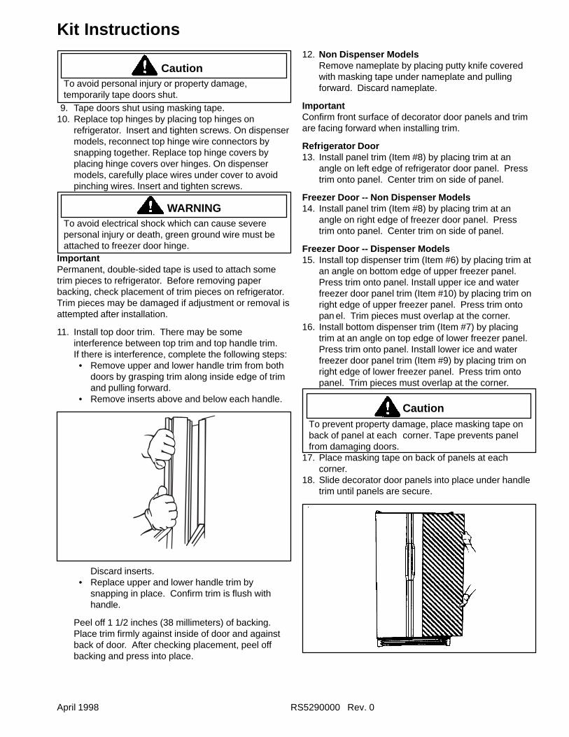
April 1998 RS5290000 Rev. 0
Kit Instructions
CautionTo avoid personal injury or property damage,temporarily tape doors shut.
9. Tape doors shut using masking tape.10. Replace top hinges by placing top hinges on
refrigerator. Insert and tighten screws. On dispensermodels, reconnect top hinge wire connectors bysnapping together. Replace top hinge covers byplacing hinge covers over hinges. On dispensermodels, carefully place wires under cover to avoidpinching wires. Insert and tighten screws.
WARNINGTo avoid electrical shock which can cause severepersonal injury or death, green ground wire must beattached to freezer door hinge.
ImportantPermanent, double-sided tape is used to attach sometrim pieces to refrigerator. Before removing paperbacking, check placement of trim pieces on refrigerator.Trim pieces may be damaged if adjustment or removal isattempted after installation.
11. Install top door trim. There may be someinterference between top trim and top handle trim.If there is interference, complete the following steps:• Remove upper and lower handle trim from both
doors by grasping trim along inside edge of trimand pulling forward.
• Remove inserts above and below each handle.
Discard inserts.• Replace upper and lower handle trim by
snapping in place. Confirm trim is flush withhandle.
Peel off 1 1/2 inches (38 millimeters) of backing.Place trim firmly against inside of door and againstback of door. After checking placement, peel offbacking and press into place.
12. Non Dispenser ModelsRemove nameplate by placing putty knife coveredwith masking tape under nameplate and pullingforward. Discard nameplate.
ImportantConfirm front surface of decorator door panels and trimare facing forward when installing trim.
Refrigerator Door13. Install panel trim (Item #8) by placing trim at an
angle on left edge of refrigerator door panel. Presstrim onto panel. Center trim on side of panel.
Freezer Door -- Non Dispenser Models14. Install panel trim (Item #8) by placing trim at an
angle on right edge of freezer door panel. Presstrim onto panel. Center trim on side of panel.
Freezer Door -- Dispenser Models15. Install top dispenser trim (Item #6) by placing trim at
an angle on bottom edge of upper freezer panel.Press trim onto panel. Install upper ice and waterfreezer door panel trim (Item #10) by placing trim onright edge of upper freezer panel. Press trim ontopan el. Trim pieces must overlap at the corner.
16. Install bottom dispenser trim (Item #7) by placingtrim at an angle on top edge of lower freezer panel.Press trim onto panel. Install lower ice and waterfreezer door panel trim (Item #9) by placing trim onright edge of lower freezer panel. Press trim ontopanel. Trim pieces must overlap at the corner.
CautionTo prevent property damage, place masking tape onback of panel at each corner. Tape prevents panelfrom damaging doors.
17. Place masking tape on back of panels at eachcorner.
18. Slide decorator door panels into place under handletrim until panels are secure.
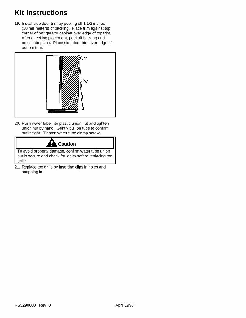
RS5290000 Rev. 0 April 1998
Kit Instructions19. Install side door trim by peeling off 1 1/2 inches
(38 millimeters) of backing. Place trim against topcorner of refrigerator cabinet over edge of top trim.After checking placement, peel off backing andpress into place. Place side door trim over edge ofbottom trim.
20. Push water tube into plastic union nut and tightenunion nut by hand. Gently pull on tube to confirmnut is tight. Tighten water tube clamp screw.
CautionTo avoid property damage, confirm water tube unionnut is secure and check for leaks before replacing toegrille.
21. Replace toe grille by inserting clips in holes andsnapping in.
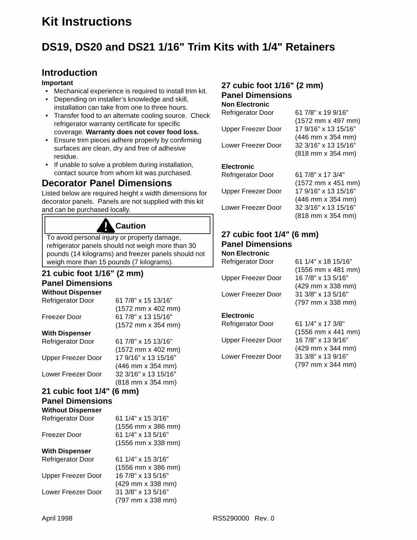
April 1998 RS5290000 Rev. 0
Kit Instructions
DS19, DS20 and DS21 1/16" Trim Kits with 1/4" Retainers
IntroductionImportant• Mechanical experience is required to install trim kit.• Depending on installer’s knowledge and skill,
installation can take from one to three hours.• Transfer food to an alternate cooling source. Check
refrigerator warranty certificate for specificcoverage. Warranty does not cover food loss.
• Ensure trim pieces adhere properly by confirmingsurfaces are clean, dry and free of adhesiveresidue.
• If unable to solve a problem during installation,contact source from whom kit was purchased.
Decorator Panel DimensionsListed below are required height x width dimensions fordecorator panels. Panels are not supplied with this kitand can be purchased locally.
CautionTo avoid personal injury or property damage,refrigerator panels should not weigh more than 30pounds (14 kilograms) and freezer panels should notweigh more than 15 pounds (7 kilograms).
21 cubic foot 1/16" (2 mm)Panel DimensionsWithout DispenserRefrigerator Door 61 7/8" x 15 13/16"
(1572 mm x 402 mm)Freezer Door 61 7/8" x 13 15/16"
(1572 mm x 354 mm)With DispenserRefrigerator Door 61 7/8" x 15 13/16"
(1572 mm x 402 mm)Upper Freezer Door 17 9/16" x 13 15/16"
(446 mm x 354 mm)Lower Freezer Door 32 3/16" x 13 15/16"
(818 mm x 354 mm)21 cubic foot 1/4" (6 mm)Panel DimensionsWithout DispenserRefrigerator Door 61 1/4" x 15 3/16"
(1556 mm x 386 mm)Freezer Door 61 1/4" x 13 5/16"
(1556 mm x 338 mm)With DispenserRefrigerator Door 61 1/4" x 15 3/16"
(1556 mm x 386 mm)Upper Freezer Door 16 7/8" x 13 5/16"
(429 mm x 338 mm)Lower Freezer Door 31 3/8" x 13 5/16"
(797 mm x 338 mm)
27 cubic foot 1/16" (2 mm)Panel DimensionsNon ElectronicRefrigerator Door 61 7/8" x 19 9/16"
(1572 mm x 497 mm)Upper Freezer Door 17 9/16" x 13 15/16"
(446 mm x 354 mm)Lower Freezer Door 32 3/16" x 13 15/16"
(818 mm x 354 mm)
ElectronicRefrigerator Door 61 7/8" x 17 3/4"
(1572 mm x 451 mm)Upper Freezer Door 17 9/16" x 13 15/16"
(446 mm x 354 mm)Lower Freezer Door 32 3/16" x 13 15/16"
(818 mm x 354 mm)
27 cubic foot 1/4" (6 mm)Panel DimensionsNon ElectronicRefrigerator Door 61 1/4" x 18 15/16"
(1556 mm x 481 mm)Upper Freezer Door 16 7/8" x 13 5/16"
(429 mm x 338 mm)Lower Freezer Door 31 3/8" x 13 5/16"
(797 mm x 338 mm)
ElectronicRefrigerator Door 61 1/4" x 17 3/8"
(1556 mm x 441 mm)Upper Freezer Door 16 7/8" x 13 9/16"
(429 mm x 344 mm)Lower Freezer Door 31 3/8" x 13 9/16"
(797 mm x 344 mm)
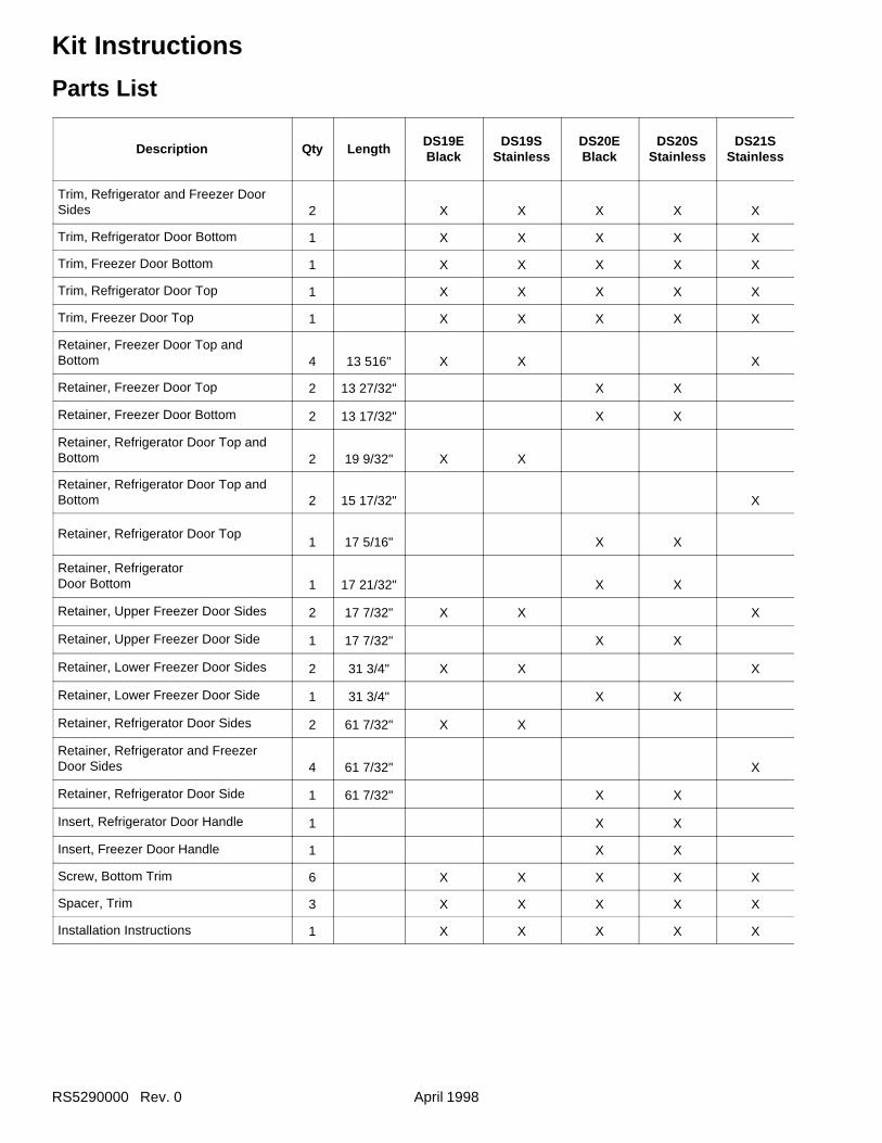
RS5290000 Rev. 0 April 1998
Kit Instructions
Parts List
Description Qty LengthDS19EBlack
DS19SStainless
DS20EBlack
DS20SStainless
DS21SStainless
Trim, Refrigerator and Freezer DoorSides 2 X X X X X
Trim, Refrigerator Door Bottom 1 X X X X X
Trim, Freezer Door Bottom 1 X X X X X
Trim, Refrigerator Door Top 1 X X X X X
Trim, Freezer Door Top 1 X X X X X
Retainer, Freezer Door Top andBottom 4 13 516" X X X
Retainer, Freezer Door Top 2 13 27/32" X X
Retainer, Freezer Door Bottom 2 13 17/32" X X
Retainer, Refrigerator Door Top andBottom 2 19 9/32" X X
Retainer, Refrigerator Door Top andBottom 2 15 17/32" X
Retainer, Refrigerator Door Top1 17 5/16" X X
Retainer, RefrigeratorDoor Bottom 1 17 21/32" X X
Retainer, Upper Freezer Door Sides 2 17 7/32" X X X
Retainer, Upper Freezer Door Side 1 17 7/32" X X
Retainer, Lower Freezer Door Sides 2 31 3/4" X X X
Retainer, Lower Freezer Door Side 1 31 3/4" X X
Retainer, Refrigerator Door Sides 2 61 7/32" X X
Retainer, Refrigerator and FreezerDoor Sides 4 61 7/32" X
Retainer, Refrigerator Door Side 1 61 7/32" X X
Insert, Refrigerator Door Handle 1 X X
Insert, Freezer Door Handle 1 X X
Screw, Bottom Trim 6 X X X X X
Spacer, Trim 3 X X X X X
Installation Instructions 1 X X X X X
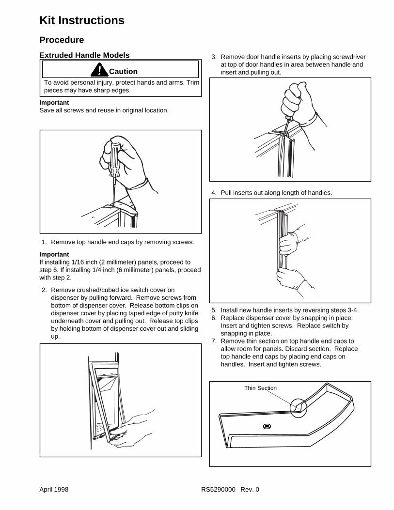
April 1998 RS5290000 Rev. 0
Kit Instructions
Procedure
Extruded Handle Models
CautionTo avoid personal injury, protect hands and arms. Trimpieces may have sharp edges.
ImportantSave all screws and reuse in original location.
3. Remove door handle inserts by placing screwdriverat top of door handles in area between handle andinsert and pulling out.
1. Remove top handle end caps by removing screws.
ImportantIf installing 1/16 inch (2 millimeter) panels, proceed tostep 6. If installing 1/4 inch (6 millimeter) panels, proceedwith step 2.
2. Remove crushed/cubed ice switch cover ondispenser by pulling forward. Remove screws frombottom of dispenser cover. Release bottom clips ondispenser cover by placing taped edge of putty knifeunderneath cover and pulling out. Release top clipsby holding bottom of dispenser cover out and slidingup.
4. Pull inserts out along length of handles.
5. Install new handle inserts by reversing steps 3-4.6. Replace dispenser cover by snapping in place.
Insert and tighten screws. Replace switch bysnapping in place.
7. Remove thin section on top handle end caps toallow room for panels. Discard section. Replacetop handle end caps by placing end caps onhandles. Insert and tighten screws.
Thin Section
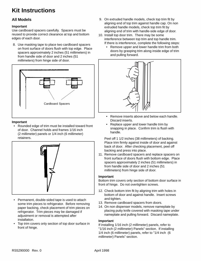
RS5290000 Rev. 0 April 1998
Kit InstructionsAll Models
ImportantUse cardboard spacers carefully. Spacers must bereused to provide correct clearance at top and bottomedges of each door.
8. Use masking tape to place two cardboard spacerson front surface of doors flush with top edge. Placespacers approximately 2 inches (51 millimeters) infrom handle side of door and 2 inches (51millimeters) from hinge side of door.
9. On extruded handle models, check top trim fit byaligning end of top trim against handle cap. On nonextruded handle models, check top trim fit byaligning end of trim with handle-side edge of door.
10. Install top door trim. There may be someinterference between top trim and top handle trim.If there is interference, complete the following steps:• Remove upper and lower handle trim from both
doors by grasping trim along inside edge of trimand pulling forward.
• Remove inserts above and below each handle.Discard inserts.
• Replace upper and lower handle trim bysnapping in place. Confirm trim is flush withhandle.
Peel off 1 1/2 inches (38 millimeters) of backing.Place trim firmly against inside of door and againstback of door. After checking placement, peel offbacking and press into place.
11. Remove cardboard spacers and replace spacers onfront surface of doors flush with bottom edge. Placespacers approximately 2 inches (51 millimeters) infrom handle side of door and 2 inches (51millimeters) from hinge side of door.
ImportantBottom trim covers only section of bottom door surface infront of hinge. Do not overtighten screws.
12. Check bottom trim fit by aligning trim with holes inbottom of door and against handle. Insert screwsand tighten.
13. Remove cardboard spacers from doors.14. On non dispenser models, remove nameplate by
placing putty knife covered with masking tape undernameplate and pulling forward. Discard nameplate.
ImportantIf installing 1/16 inch (2 millimeter) panels, refer to"1/16 inch (2 millimeter) Panels" section. If installing1/4 inch (6 millimeter) panels, refer to "1/4 inch (6millimeter) Panels" section.
Important• Rounded edge of trim must be installed toward front
of door. Channel holds and frames 1/16 inch(2 millimeter) panels or 1/4 inch (6 millimeter)retainers.
• Permanent, double-sided tape is used to attachsome trim pieces to refrigerator. Before removingpaper backing, check placement of trim pieces onrefrigerator. Trim pieces may be damaged ifadjustment or removal is attempted afterinstallation.
• Top trim covers only section of top door surface infront of hinge.
Cardboard Spacers
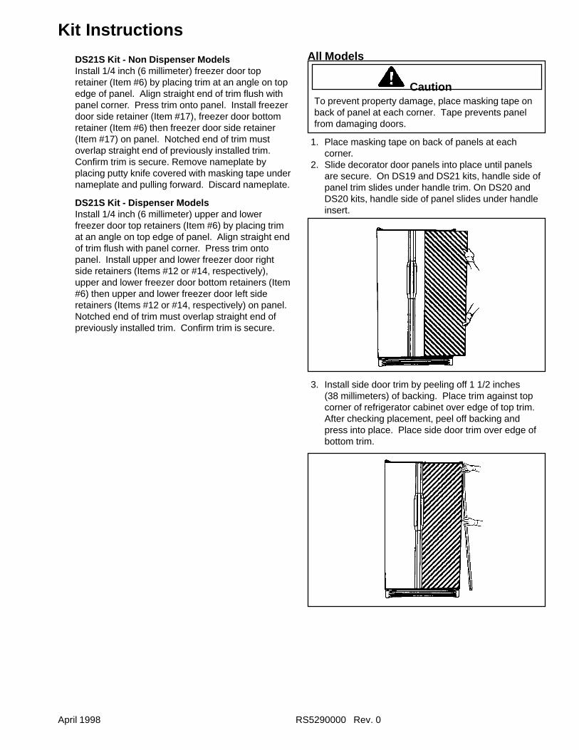
April 1998 RS5290000 Rev. 0
Kit Instructions
DS21S Kit - Non Dispenser ModelsInstall 1/4 inch (6 millimeter) freezer door topretainer (Item #6) by placing trim at an angle on topedge of panel. Align straight end of trim flush withpanel corner. Press trim onto panel. Install freezerdoor side retainer (Item #17), freezer door bottomretainer (Item #6) then freezer door side retainer(Item #17) on panel. Notched end of trim mustoverlap straight end of previously installed trim.Confirm trim is secure. Remove nameplate byplacing putty knife covered with masking tape undernameplate and pulling forward. Discard nameplate.
DS21S Kit - Dispenser ModelsInstall 1/4 inch (6 millimeter) upper and lowerfreezer door top retainers (Item #6) by placing trimat an angle on top edge of panel. Align straight endof trim flush with panel corner. Press trim ontopanel. Install upper and lower freezer door rightside retainers (Items #12 or #14, respectively),upper and lower freezer door bottom retainers (Item#6) then upper and lower freezer door left sideretainers (Items #12 or #14, respectively) on panel.Notched end of trim must overlap straight end ofpreviously installed trim. Confirm trim is secure.
All Models
CautionTo prevent property damage, place masking tape onback of panel at each corner. Tape prevents panelfrom damaging doors.
1. Place masking tape on back of panels at eachcorner.
2. Slide decorator door panels into place until panelsare secure. On DS19 and DS21 kits, handle side ofpanel trim slides under handle trim. On DS20 andDS20 kits, handle side of panel slides under handleinsert.
3. Install side door trim by peeling off 1 1/2 inches(38 millimeters) of backing. Place trim against topcorner of refrigerator cabinet over edge of top trim.After checking placement, peel off backing andpress into place. Place side door trim over edge ofbottom trim.
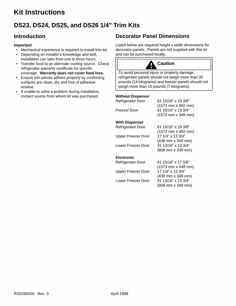
RS5290000 Rev. 0 April 1998
Kit Instructions
DS23, DS24, DS25, and DS26 1/4" Trim Kits
Introduction
Important• Mechanical experience is required to install trim kit.• Depending on installer’s knowledge and skill,
installation can take from one to three hours.• Transfer food to an alternate cooling source. Check
refrigerator warranty certificate for specificcoverage. Warranty does not cover food loss.
• Ensure trim pieces adhere properly by confirmingsurfaces are clean, dry and free of adhesiveresidue.
• If unable to solve a problem during installation,contact source from whom kit was purchased.
Decorator Panel Dimensions
Listed below are required height x width dimensions fordecorator panels. Panels are not supplied with this kitand can be purchased locally.
Caution
To avoid personal injury or property damage,refrigerator panels should not weigh more than 30pounds (14 kilograms) and freezer panels should notweigh more than 15 pounds (7 kilograms).
Without DispenserRefrigerator Door 61 15/16" x 19 3/8"
(1573 mm x 492 mm)Freezer Door 61 15/16" x 13 3/4"
(1573 mm x 349 mm)
With DispenserRefrigerator Door 61 15/16" x 19 3/8"
(1573 mm x 492 mm)Upper Freezer Door 17 1/4" x 13 3/4"
(438 mm x 349 mm)Lower Freezer Door 31 13/16" x 13 3/4"
(808 mm x 349 mm)
ElectronicRefrigerator Door 61 15/16" x 17 5/8"
(1573 mm x 448 mm)Upper Freezer Door 17 1/4" x 13 3/4"
(438 mm x 349 mm)Lower Freezer Door 31 13/16" x 13 3/4"
(808 mm x 349 mm)
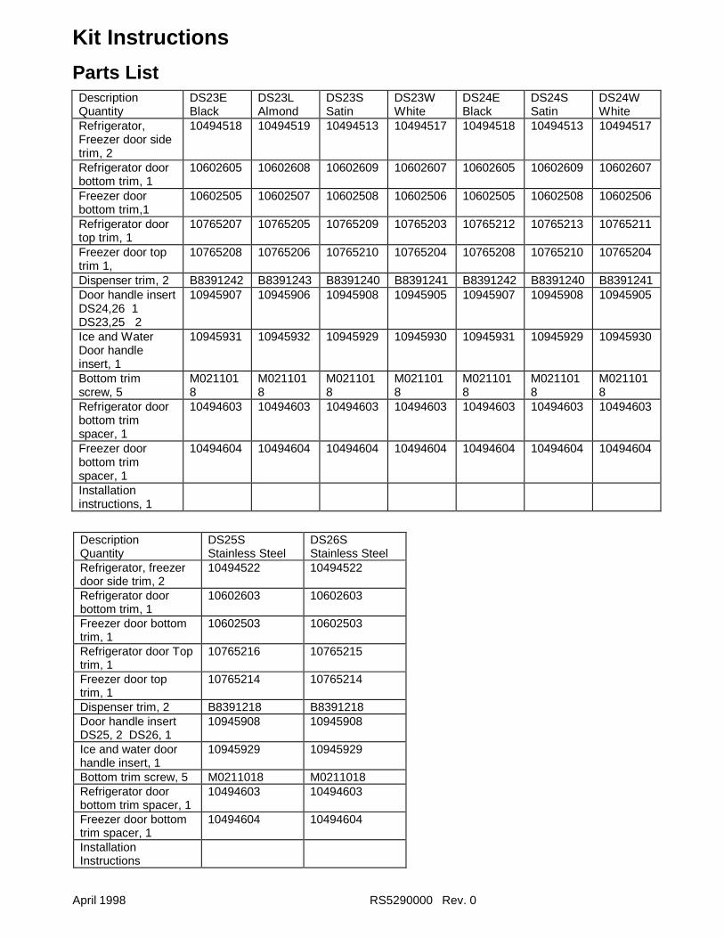
April 1998 RS5290000 Rev. 0
Kit Instructions
Parts ListDescriptionQuantity
DS23EBlack
DS23LAlmond
DS23SSatin
DS23WWhite
DS24EBlack
DS24SSatin
DS24WWhite
Refrigerator,Freezer door sidetrim, 2
10494518 10494519 10494513 10494517 10494518 10494513 10494517
Refrigerator doorbottom trim, 1
10602605 10602608 10602609 10602607 10602605 10602609 10602607
Freezer doorbottom trim,1
10602505 10602507 10602508 10602506 10602505 10602508 10602506
Refrigerator doortop trim, 1
10765207 10765205 10765209 10765203 10765212 10765213 10765211
Freezer door toptrim 1,
10765208 10765206 10765210 10765204 10765208 10765210 10765204
Dispenser trim, 2 B8391242 B8391243 B8391240 B8391241 B8391242 B8391240 B8391241Door handle insertDS24,26 1DS23,25 2
10945907 10945906 10945908 10945905 10945907 10945908 10945905
Ice and WaterDoor handleinsert, 1
10945931 10945932 10945929 10945930 10945931 10945929 10945930
Bottom trimscrew, 5
M0211018
M0211018
M0211018
M0211018
M0211018
M0211018
M0211018
Refrigerator doorbottom trimspacer, 1
10494603 10494603 10494603 10494603 10494603 10494603 10494603
Freezer doorbottom trimspacer, 1
10494604 10494604 10494604 10494604 10494604 10494604 10494604
Installationinstructions, 1
DescriptionQuantity
DS25SStainless Steel
DS26SStainless Steel
Refrigerator, freezerdoor side trim, 2
10494522 10494522
Refrigerator doorbottom trim, 1
10602603 10602603
Freezer door bottomtrim, 1
10602503 10602503
Refrigerator door Toptrim, 1
10765216 10765215
Freezer door toptrim, 1
10765214 10765214
Dispenser trim, 2 B8391218 B8391218Door handle insertDS25, 2 DS26, 1
10945908 10945908
Ice and water doorhandle insert, 1
10945929 10945929
Bottom trim screw, 5 M0211018 M0211018Refrigerator doorbottom trim spacer, 1
10494603 10494603
Freezer door bottomtrim spacer, 1
10494604 10494604
InstallationInstructions
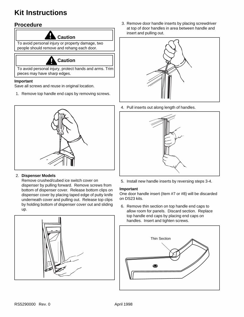
RS5290000 Rev. 0 April 1998
Kit Instructions
Procedure
CautionTo avoid personal injury or property damage, twopeople should remove and rehang each door.
Caution
To avoid personal injury, protect hands and arms. Trimpieces may have sharp edges.
ImportantSave all screws and reuse in original location.
1. Remove top handle end caps by removing screws.
2. Dispenser ModelsRemove crushed/cubed ice switch cover ondispenser by pulling forward. Remove screws frombottom of dispenser cover. Release bottom clips ondispenser cover by placing taped edge of putty knifeunderneath cover and pulling out. Release top clipsby holding bottom of dispenser cover out and slidingup.
3. Remove door handle inserts by placing screwdriverat top of door handles in area between handle andinsert and pulling out.
4. Pull inserts out along length of handles.
5. Install new handle inserts by reversing steps 3-4.
ImportantOne door handle insert (Item #7 or #8) will be discardedon DS23 kits.
6. Remove thin section on top handle end caps toallow room for panels. Discard section. Replacetop handle end caps by placing end caps onhandles. Insert and tighten screws.
Thin Section
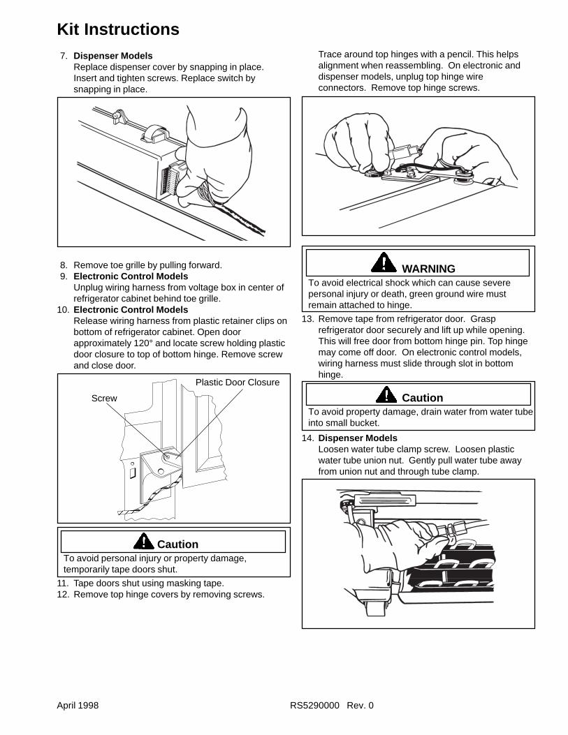
April 1998 RS5290000 Rev. 0
Kit InstructionsTrace around top hinges with a pencil. This helpsalignment when reassembling. On electronic anddispenser models, unplug top hinge wireconnectors. Remove top hinge screws.
WARNINGTo avoid electrical shock which can cause severepersonal injury or death, green ground wire mustremain attached to hinge.
13. Remove tape from refrigerator door. Grasprefrigerator door securely and lift up while opening.This will free door from bottom hinge pin. Top hingemay come off door. On electronic control models,wiring harness must slide through slot in bottomhinge.
CautionTo avoid property damage, drain water from water tubeinto small bucket.
14. Dispenser ModelsLoosen water tube clamp screw. Loosen plasticwater tube union nut. Gently pull water tube awayfrom union nut and through tube clamp.
7. Dispenser ModelsReplace dispenser cover by snapping in place.Insert and tighten screws. Replace switch bysnapping in place.
8. Remove toe grille by pulling forward.9. Electronic Control Models
Unplug wiring harness from voltage box in center ofrefrigerator cabinet behind toe grille.
10. Electronic Control ModelsRelease wiring harness from plastic retainer clips onbottom of refrigerator cabinet. Open doorapproximately 120° and locate screw holding plasticdoor closure to top of bottom hinge. Remove screwand close door.
CautionTo avoid personal injury or property damage,temporarily tape doors shut.
11. Tape doors shut using masking tape.12. Remove top hinge covers by removing screws.
Plastic Door Closure
Screw
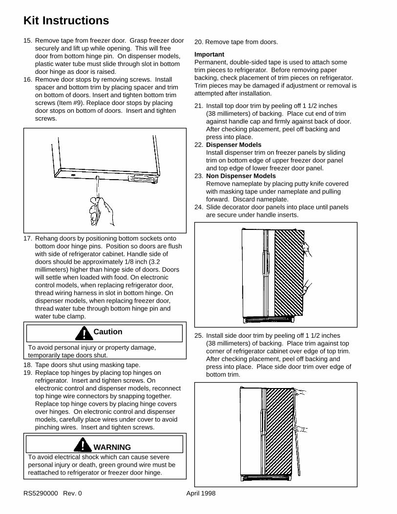
RS5290000 Rev. 0 April 1998
Kit Instructions
15. Remove tape from freezer door. Grasp freezer doorsecurely and lift up while opening. This will freedoor from bottom hinge pin. On dispenser models,plastic water tube must slide through slot in bottomdoor hinge as door is raised.
16. Remove door stops by removing screws. Installspacer and bottom trim by placing spacer and trimon bottom of doors. Insert and tighten bottom trimscrews (Item #9). Replace door stops by placingdoor stops on bottom of doors. Insert and tightenscrews.
17. Rehang doors by positioning bottom sockets ontobottom door hinge pins. Position so doors are flushwith side of refrigerator cabinet. Handle side ofdoors should be approximately 1/8 inch (3.2millimeters) higher than hinge side of doors. Doorswill settle when loaded with food. On electroniccontrol models, when replacing refrigerator door,thread wiring harness in slot in bottom hinge. Ondispenser models, when replacing freezer door,thread water tube through bottom hinge pin andwater tube clamp.
Caution
To avoid personal injury or property damage,temporarily tape doors shut.
18. Tape doors shut using masking tape.19. Replace top hinges by placing top hinges on
refrigerator. Insert and tighten screws. Onelectronic control and dispenser models, reconnecttop hinge wire connectors by snapping together.Replace top hinge covers by placing hinge coversover hinges. On electronic control and dispensermodels, carefully place wires under cover to avoidpinching wires. Insert and tighten screws.
WARNINGTo avoid electrical shock which can cause severepersonal injury or death, green ground wire must bereattached to refrigerator or freezer door hinge.
20. Remove tape from doors.
ImportantPermanent, double-sided tape is used to attach sometrim pieces to refrigerator. Before removing paperbacking, check placement of trim pieces on refrigerator.Trim pieces may be damaged if adjustment or removal isattempted after installation.
21. Install top door trim by peeling off 1 1/2 inches(38 millimeters) of backing. Place cut end of trimagainst handle cap and firmly against back of door.After checking placement, peel off backing andpress into place.
22. Dispenser ModelsInstall dispenser trim on freezer panels by slidingtrim on bottom edge of upper freezer door paneland top edge of lower freezer door panel.
23. Non Dispenser ModelsRemove nameplate by placing putty knife coveredwith masking tape under nameplate and pullingforward. Discard nameplate.
24. Slide decorator door panels into place until panelsare secure under handle inserts.
25. Install side door trim by peeling off 1 1/2 inches(38 millimeters) of backing. Place trim against topcorner of refrigerator cabinet over edge of top trim.After checking placement, peel off backing andpress into place. Place side door trim over edge ofbottom trim.
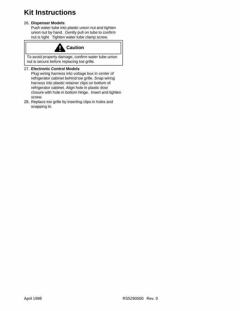
April 1998 RS5290000 Rev. 0
Kit Instructions26. Dispenser Models
Push water tube into plastic union nut and tightenunion nut by hand. Gently pull on tube to confirmnut is tight. Tighten water tube clamp screw.
Caution
To avoid property damage, confirm water tube unionnut is secure before replacing toe grille.
27. Electronic Control ModelsPlug wiring harness into voltage box in center ofrefrigerator cabinet behind toe grille. Snap wiringharness into plastic retainer clips on bottom ofrefrigerator cabinet. Align hole in plastic doorclosure with hole in bottom hinge. Insert and tightenscrew.
28. Replace toe grille by inserting clips in holes andsnapping in.
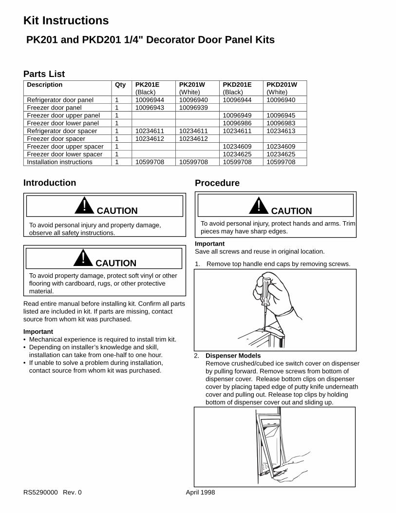
RS5290000 Rev. 0 April 1998
Kit Instructions
Procedure
! CAUTIONTo avoid personal injury, protect hands and arms. Trimpieces may have sharp edges.
ImportantSave all screws and reuse in original location.
1. Remove top handle end caps by removing screws.
Introduction
! CAUTIONTo avoid personal injury and property damage,observe all safety instructions.
! CAUTIONTo avoid property damage, protect soft vinyl or otherflooring with cardboard, rugs, or other protectivematerial.
Read entire manual before installing kit. Confirm all partslisted are included in kit. If parts are missing, contactsource from whom kit was purchased.
Important• Mechanical experience is required to install trim kit.• Depending on installer’s knowledge and skill,
installation can take from one-half to one hour.• If unable to solve a problem during installation,
contact source from whom kit was purchased.
2. Dispenser ModelsRemove crushed/cubed ice switch cover on dispenserby pulling forward. Remove screws from bottom ofdispenser cover. Release bottom clips on dispensercover by placing taped edge of putty knife underneathcover and pulling out. Release top clips by holdingbottom of dispenser cover out and sliding up.
Description Qty PK201E(Black)
PK201W(White)
PKD201E(Black)
PKD201W(White)
Refrigerator door panel 1 10096944 10096940 10096944 10096940Freezer door panel 1 10096943 10096939Freezer door upper panel 1 10096949 10096945Freezer door lower panel 1 10096986 10096983Refrigerator door spacer 1 10234611 10234611 10234611 10234613Freezer door spacer 1 10234612 10234612Freezer door upper spacer 1 10234609 10234609Freezer door lower spacer 1 10234625 10234625Installation instructions 1 10599708 10599708 10599708 10599708
Parts List
PK201 and PKD201 1/4" Decorator Door Panel Kits
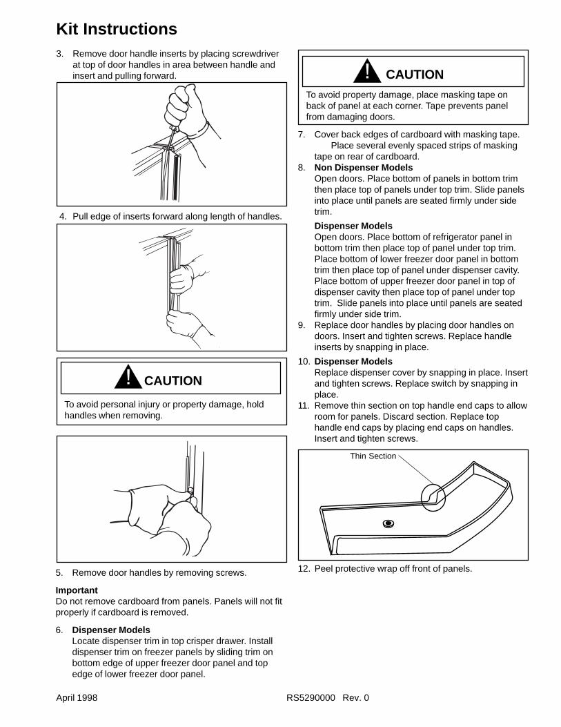
April 1998 RS5290000 Rev. 0
Kit Instructions3. Remove door handle inserts by placing screwdriver
at top of door handles in area between handle andinsert and pulling forward.
4. Pull edge of inserts forward along length of handles.
CAUTIONTo avoid property damage, place masking tape onback of panel at each corner. Tape prevents panelfrom damaging doors.
7. Cover back edges of cardboard with masking tape.Place several evenly spaced strips of masking
tape on rear of cardboard.8. Non Dispenser Models
Open doors. Place bottom of panels in bottom trimthen place top of panels under top trim. Slide panelsinto place until panels are seated firmly under sidetrim.
Dispenser ModelsOpen doors. Place bottom of refrigerator panel inbottom trim then place top of panel under top trim.Place bottom of lower freezer door panel in bottomtrim then place top of panel under dispenser cavity.Place bottom of upper freezer door panel in top ofdispenser cavity then place top of panel under toptrim. Slide panels into place until panels are seatedfirmly under side trim.
9. Replace door handles by placing door handles ondoors. Insert and tighten screws. Replace handleinserts by snapping in place.
10. Dispenser ModelsReplace dispenser cover by snapping in place. Insertand tighten screws. Replace switch by snapping inplace.
11. Remove thin section on top handle end caps to allowroom for panels. Discard section. Replace tophandle end caps by placing end caps on handles.Insert and tighten screws.
12. Peel protective wrap off front of panels.
Thin Section
5. Remove door handles by removing screws.
ImportantDo not remove cardboard from panels. Panels will not fitproperly if cardboard is removed.
6. Dispenser ModelsLocate dispenser trim in top crisper drawer. Installdispenser trim on freezer panels by sliding trim onbottom edge of upper freezer door panel and topedge of lower freezer door panel.
CAUTION
To avoid personal injury or property damage, holdhandles when removing.
!
!
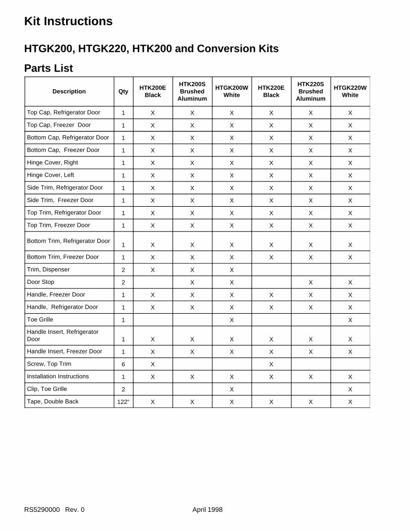
RS5290000 Rev. 0 April 1998
Kit Instructions
HTGK200, HTGK220, HTK200 and Conversion Kits
Parts List
Description QtyHTK200E
Black
HTK200SBrushed
Aluminum
HTGK200WWhite
HTK220EBlack
HTK220SBrushed
Aluminum
HTGK220WWhite
Top Cap, Refrigerator Door 1 X X X X X X
Top Cap, Freezer Door 1 X X X X X X
Bottom Cap, Refrigerator Door 1 X X X X X X
Bottom Cap, Freezer Door 1 X X X X X X
Hinge Cover, Right 1 X X X X X X
Hinge Cover, Left 1 X X X X X X
Side Trim, Refrigerator Door 1 X X X X X X
Side Trim, Freezer Door 1 X X X X X X
Top Trim, Refrigerator Door 1 X X X X X X
Top Trim, Freezer Door 1 X X X X X X
Bottom Trim, Refrigerator Door1 X X X X X X
Bottom Trim, Freezer Door 1 X X X X X X
Trim, Dispenser 2 X X X
Door Stop 2 X X X X
Handle, Freezer Door 1 X X X X X X
Handle, Refrigerator Door 1 X X X X X X
Toe Grille 1 X X
Handle Insert, RefrigeratorDoor 1 X X X X X X
Handle Insert, Freezer Door 1 X X X X X X
Screw, Top Trim 6 X X
Installation Instructions 1 X X X X X X
Clip, Toe Grille 2 X X
Tape, Double Back 122" X X X X X X
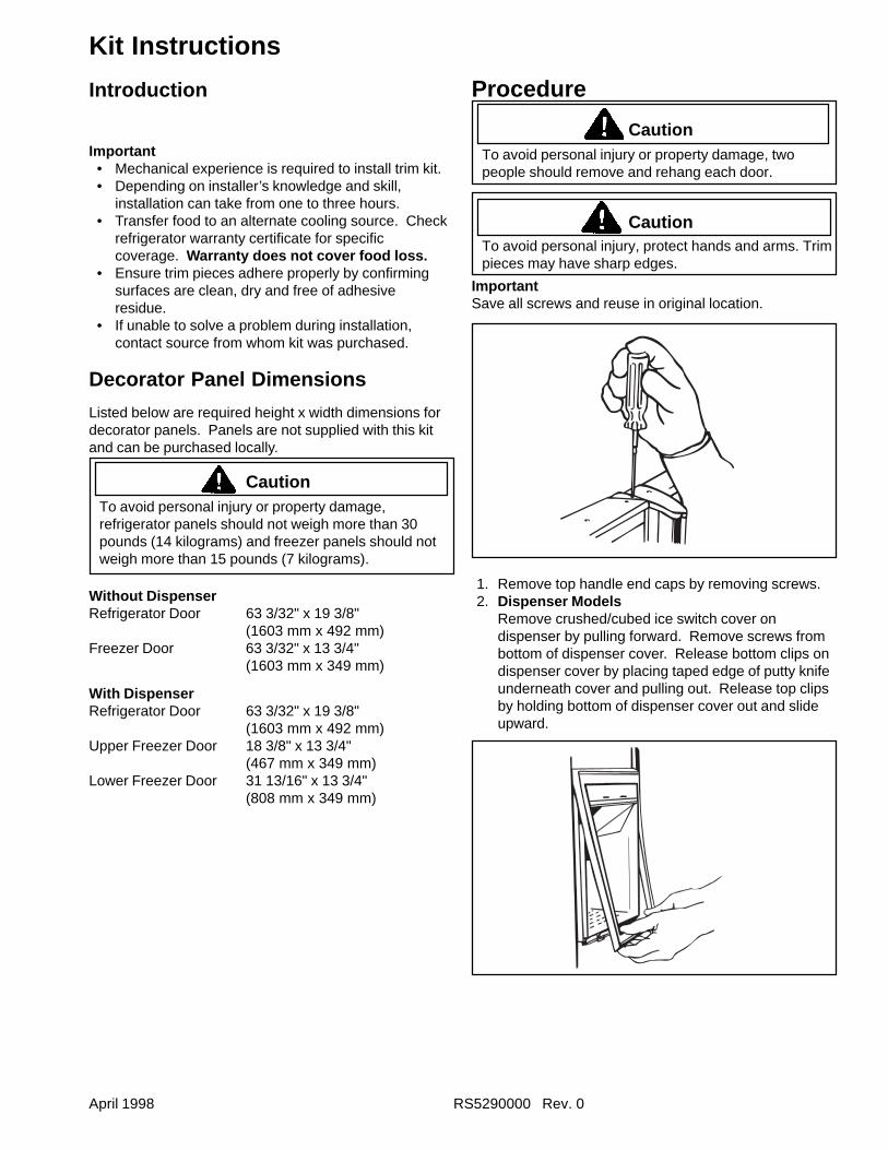
April 1998 RS5290000 Rev. 0
Kit Instructions
Introduction
Important• Mechanical experience is required to install trim kit.• Depending on installer’s knowledge and skill,
installation can take from one to three hours.• Transfer food to an alternate cooling source. Check
refrigerator warranty certificate for specificcoverage. Warranty does not cover food loss.
• Ensure trim pieces adhere properly by confirmingsurfaces are clean, dry and free of adhesiveresidue.
• If unable to solve a problem during installation,contact source from whom kit was purchased.
Decorator Panel Dimensions
Listed below are required height x width dimensions fordecorator panels. Panels are not supplied with this kitand can be purchased locally.
CautionTo avoid personal injury or property damage,refrigerator panels should not weigh more than 30pounds (14 kilograms) and freezer panels should notweigh more than 15 pounds (7 kilograms).
Without DispenserRefrigerator Door 63 3/32" x 19 3/8"
(1603 mm x 492 mm)Freezer Door 63 3/32" x 13 3/4"
(1603 mm x 349 mm)
With DispenserRefrigerator Door 63 3/32" x 19 3/8"
(1603 mm x 492 mm)Upper Freezer Door 18 3/8" x 13 3/4"
(467 mm x 349 mm)Lower Freezer Door 31 13/16" x 13 3/4"
(808 mm x 349 mm)
Procedure
CautionTo avoid personal injury or property damage, twopeople should remove and rehang each door.
CautionTo avoid personal injury, protect hands and arms. Trimpieces may have sharp edges.
ImportantSave all screws and reuse in original location.
1. Remove top handle end caps by removing screws.2. Dispenser Models
Remove crushed/cubed ice switch cover ondispenser by pulling forward. Remove screws frombottom of dispenser cover. Release bottom clips ondispenser cover by placing taped edge of putty knifeunderneath cover and pulling out. Release top clipsby holding bottom of dispenser cover out and slideupward.
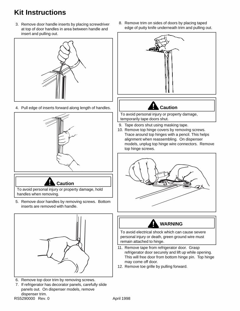
RS5290000 Rev. 0 April 1998
Kit Instructions
3. Remove door handle inserts by placing screwdriverat top of door handles in area between handle andinsert and pulling out.
4. Pull edge of inserts forward along length of handles.
CautionTo avoid personal injury or property damage, holdhandles when removing.
5. Remove door handles by removing screws. Bottominserts are removed with handle.
6. Remove top door trim by removing screws.7. If refrigerator has decorator panels, carefully slide
panels out. On dispenser models, removedispenser trim.
8. Remove trim on sides of doors by placing tapededge of putty knife underneath trim and pulling out.
CautionTo avoid personal injury or property damage,temporarily tape doors shut.
9. Tape doors shut using masking tape.10. Remove top hinge covers by removing screws.
Trace around top hinges with a pencil. This helpsalignment when reassembling. On dispensermodels, unplug top hinge wire connectors. Removetop hinge screws.
WARNING
To avoid electrical shock which can cause severepersonal injury or death, green ground wire mustremain attached to hinge.
11. Remove tape from refrigerator door. Grasprefrigerator door securely and lift up while opening.This will free door from bottom hinge pin. Top hingemay come off door.
12. Remove toe grille by pulling forward.
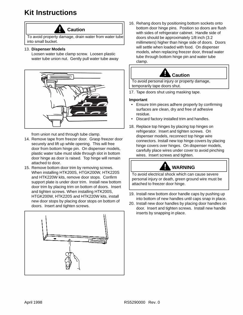
April 1998 RS5290000 Rev. 0
Kit Instructions
CautionTo avoid property damage, drain water from water tubeinto small bucket.
13. Dispenser ModelsLoosen water tube clamp screw. Loosen plasticwater tube union nut. Gently pull water tube away
from union nut and through tube clamp.14. Remove tape from freezer door. Grasp freezer door
securely and lift up while opening. This will freedoor from bottom hinge pin. On dispenser models,plastic water tube must slide through slot in bottomdoor hinge as door is raised. Top hinge will remainattached to door.
15. Remove bottom door trim by removing screws.When installing HTK200S, HTGK200W, HTK220Sand HTK220W kits, remove door stops. Confirmsupport plate is under door trim. Install new bottomdoor trim by placing trim on bottom of doors. Insertand tighten screws. When installing HTK200S,HTGK200W, HTK220S and HTK220W kits, installnew door stops by placing door stops on bottom ofdoors. Insert and tighten screws.
16. Rehang doors by positioning bottom sockets ontobottom door hinge pins. Position so doors are flushwith sides of refrigerator cabinet. Handle side ofdoors should be approximately 1/8 inch (3.2millimeters) higher than hinge side of doors. Doorswill settle when loaded with food. On dispensermodels, when replacing freezer door, thread watertube through bottom hinge pin and water tubeclamp.
CautionTo avoid personal injury or property damage,temporarily tape doors shut.
17. Tape doors shut using masking tape.
Important• Ensure trim pieces adhere properly by confirming
surfaces are clean, dry and free of adhesiveresidue.
• Discard factory installed trim and handles.
18. Replace top hinges by placing top hinges onrefrigerator. Insert and tighten screws. Ondispenser models, reconnect top hinge wireconnectors. Install new top hinge covers by placinghinge covers over hinges. On dispenser models,carefully place wires under cover to avoid pinchingwires. Insert screws and tighten.
WARNINGTo avoid electrical shock which can cause severepersonal injury or death, green ground wire must beattached to freezer door hinge.
19. Install new bottom door handle caps by pushing upinto bottom of new handles until caps snap in place.
20. Install new door handles by placing door handles ondoor. Insert and tighten screws. Install new handleinserts by snapping in place.
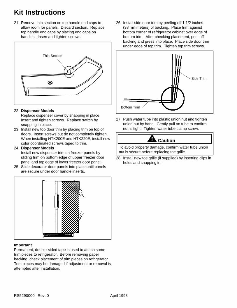
RS5290000 Rev. 0 April 1998
Kit Instructions
Thin Section
21. Remove thin section on top handle end caps toallow room for panels. Discard section. Replacetop handle end caps by placing end caps onhandles. Insert and tighten screws.
22. Dispenser ModelsReplace dispenser cover by snapping in place.Insert and tighten screws. Replace switch bysnapping in place.
23. Install new top door trim by placing trim on top ofdoors. Insert screws but do not completely tighten.When installing HTK200E and HTK220E, install newcolor coordinated screws taped to trim.
24. Dispenser ModelsInstall new dispenser trim on freezer panels bysliding trim on bottom edge of upper freezer doorpanel and top edge of lower freezer door panel.
25. Slide decorator door panels into place until panelsare secure under door handle inserts.
ImportantPermanent, double-sided tape is used to attach sometrim pieces to refrigerator. Before removing paperbacking, check placement of trim pieces on refrigerator.Trim pieces may be damaged if adjustment or removal isattempted after installation.
26. Install side door trim by peeling off 1 1/2 inches(38 millimeters) of backing. Place trim againstbottom corner of refrigerator cabinet over edge ofbottom trim. After checking placement, peel offbacking and press into place. Place side door trimunder edge of top trim. Tighten top trim screws.
27. Push water tube into plastic union nut and tightenunion nut by hand. Gently pull on tube to confirmnut is tight. Tighten water tube clamp screw.
CautionTo avoid property damage, confirm water tube unionnut is secure before replacing toe grille.
28. Install new toe grille (if supplied) by inserting clips inholes and snapping in.
Side Trim
Bottom Trim
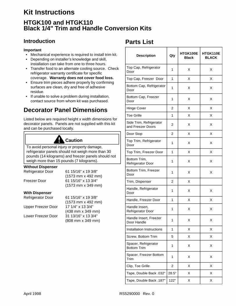
April 1998 RS5290000 Rev. 0
Kit InstructionsHTGK100 and HTGK110
Introduction
Important• Mechanical experience is required to install trim kit.• Depending on installer’s knowledge and skill,
installation can take from one to three hours.• Transfer food to an alternate cooling source. Check
refrigerator warranty certificate for specificcoverage. Warranty does not cover food loss.
• Ensure trim pieces adhere properly by confirmingsurfaces are clean, dry and free of adhesiveresidue.
• If unable to solve a problem during installation,contact source from whom kit was purchased.
Decorator Panel DimensionsListed below are required height x width dimensions fordecorator panels. Panels are not supplied with this kitand can be purchased locally.
CautionTo avoid personal injury or property damage,refrigerator panels should not weigh more than 30pounds (14 kilograms) and freezer panels should notweigh more than 15 pounds (7 kilograms).
Without DispenserRefrigerator Door 61 15/16" x 19 3/8"
(1573 mm x 492 mm)Freezer Door 61 15/16" x 13 3/4"
(1573 mm x 349 mm)
With DispenserRefrigerator Door 61 15/16" x 19 3/8"
(1573 mm x 492 mm)Upper Freezer Door 17 1/4" x 13 3/4"
(438 mm x 349 mm)Lower Freezer Door 31 13/16" x 13 3/4"
(808 mm x 349 mm)
Parts List
Description QtyHTGK100E
BlackHTGK110E
BLACK
Top Cap, RefrigeratorDoor
1 X X
Top Cap, Freezer Door 1 X X
Bottom Cap, RefrigeratorDoor
1 X X
Bottom Cap, FreezerDoor
1 X X
Hinge Cover 2 X X
Toe Grille 1 X X
Side Trim, Refrigeratorand Freezer Doors
2 X X
Door Stop 2 X X
Top Trim, RefrigeratorDoor
1 X X
Top Trim, Freezer Door 1 X X
Bottom Trim,Refrigerator Door
1 X X
Bottom Trim, FreezerDoor
1 X X
Trim, Dispenser 2 X
Handle, RefrigeratorDoor
1 X X
Handle, Freezer Door 1 X X
Handle Insert,Refrigerator Door
1 X X
Handle Insert, FreezerDoor Handle
1 X X
Installation Instructions 1 X X
Screw, Bottom Trim 5 X X
Spacer, RefrigeratorBottom Trim
1 X X
Spacer, Freezer BottomTrim
1 X X
Clip, Toe Grille 2 X X
Tape, Double Back .032" 28.5" X X
Tape, Double Back .187" 122" X X
Black 1/4" Trim and Handle Conversion Kits
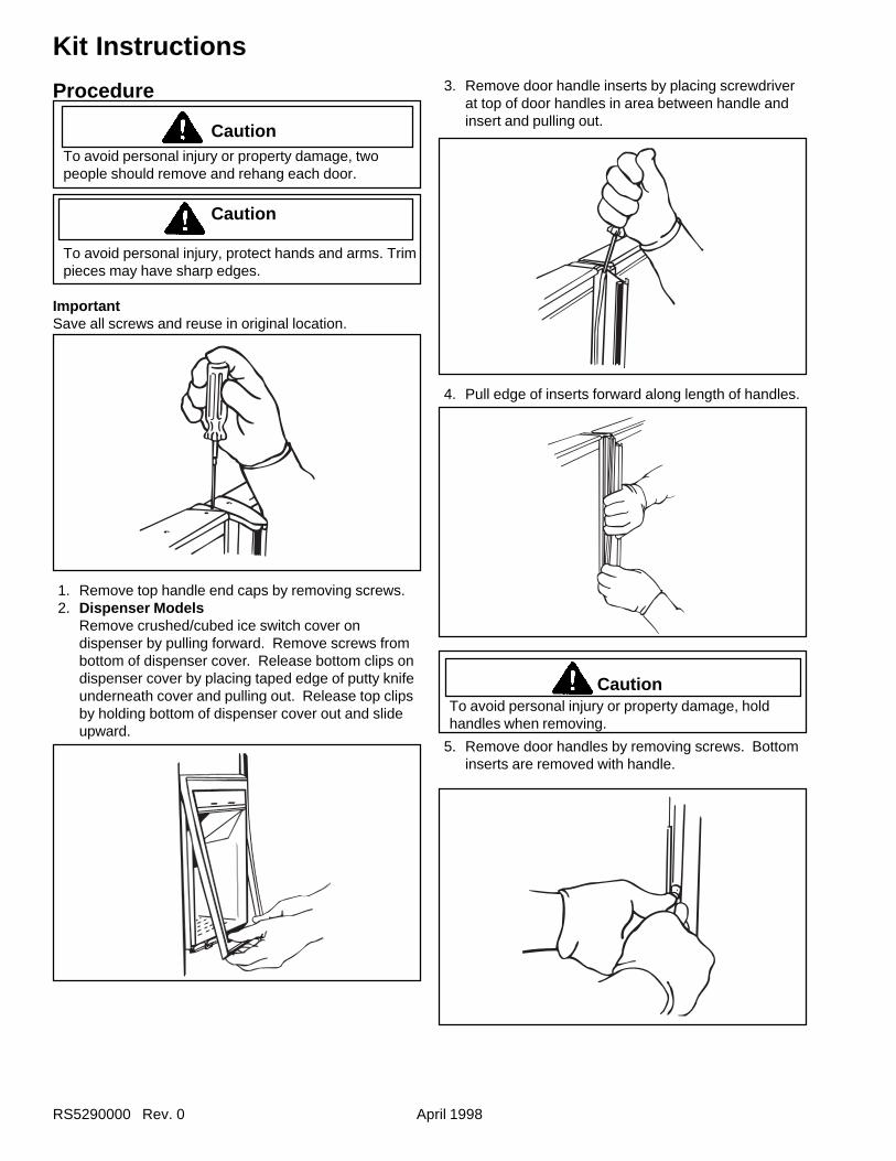
RS5290000 Rev. 0 April 1998
Kit Instructions
Procedure
CautionTo avoid personal injury or property damage, twopeople should remove and rehang each door.
Caution
To avoid personal injury, protect hands and arms. Trimpieces may have sharp edges.
ImportantSave all screws and reuse in original location.
1. Remove top handle end caps by removing screws.2. Dispenser Models
Remove crushed/cubed ice switch cover ondispenser by pulling forward. Remove screws frombottom of dispenser cover. Release bottom clips ondispenser cover by placing taped edge of putty knifeunderneath cover and pulling out. Release top clipsby holding bottom of dispenser cover out and slideupward.
3. Remove door handle inserts by placing screwdriverat top of door handles in area between handle andinsert and pulling out.
4. Pull edge of inserts forward along length of handles.
CautionTo avoid personal injury or property damage, holdhandles when removing.
5. Remove door handles by removing screws. Bottominserts are removed with handle.
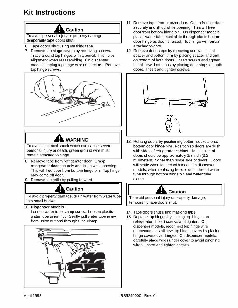
April 1998 RS5290000 Rev. 0
Kit Instructions
CautionTo avoid personal injury or property damage,temporarily tape doors shut.
6. Tape doors shut using masking tape.7. Remove top hinge covers by removing screws.
Trace around top hinges with a pencil. This helpsalignment when reassembling. On dispensermodels, unplug top hinge wire connectors. Removetop hinge screws.
WARNINGTo avoid electrical shock which can cause severepersonal injury or death, green ground wire mustremain attached to hinge.
8. Remove tape from refrigerator door. Grasprefrigerator door securely and lift up while opening.This will free door from bottom hinge pin. Top hingemay come off door.
9. Remove toe grille by pulling forward.
Caution
To avoid property damage, drain water from water tubeinto small bucket.
10. Dispenser ModelsLoosen water tube clamp screw. Loosen plasticwater tube union nut. Gently pull water tube awayfrom union nut and through tube clamp.
11. Remove tape from freezer door. Grasp freezer doorsecurely and lift up while opening. This will freedoor from bottom hinge pin. On dispenser models,plastic water tube must slide through slot in bottomdoor hinge as door is raised. Top hinge will remainattached to door.
12. Remove door stops by removing screws. Installspacer and bottom trim by placing spacer and trimon bottom of both doors. Insert screws and tighten.Install new door stops by placing door stops on bothdoors. Insert and tighten screws.
13. Rehang doors by positioning bottom sockets ontobottom door hinge pins. Position so doors are flushwith sides of refrigerator cabinet. Handle side ofdoors should be approximately 1/8 inch (3.2millimeters) higher than hinge side of doors. Doorswill settle when loaded with food. On dispensermodels, when replacing freezer door, thread watertube through bottom hinge pin and water tubeclamp.
CautionTo avoid personal injury or property damage,temporarily tape doors shut.
14. Tape doors shut using masking tape.15. Replace top hinges by placing top hinges on
refrigerator. Insert screws and tighten. Ondispenser models, reconnect top hinge wireconnectors. Install new top hinge covers by placinghinge covers over hinges. On dispenser models,carefully place wires under cover to avoid pinchingwires. Insert and tighten screws.
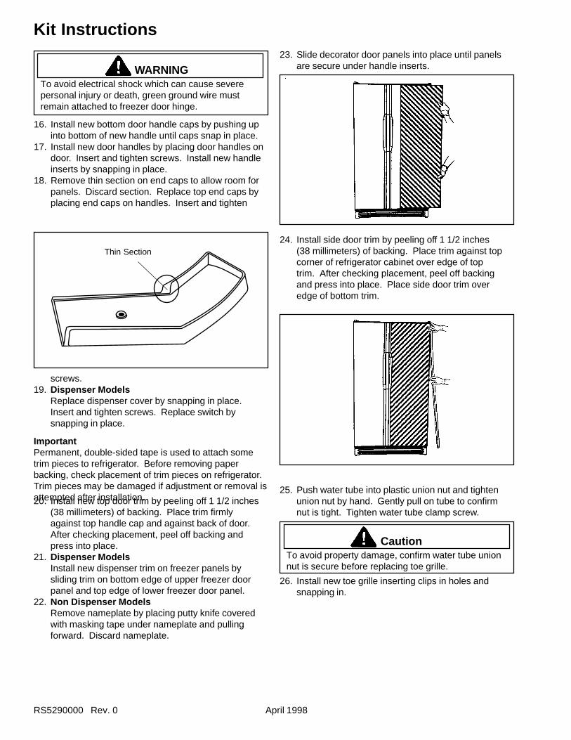
RS5290000 Rev. 0 April 1998
Kit Instructions
Thin Section
WARNINGTo avoid electrical shock which can cause severepersonal injury or death, green ground wire mustremain attached to freezer door hinge.
16. Install new bottom door handle caps by pushing upinto bottom of new handle until caps snap in place.
17. Install new door handles by placing door handles ondoor. Insert and tighten screws. Install new handleinserts by snapping in place.
18. Remove thin section on end caps to allow room forpanels. Discard section. Replace top end caps byplacing end caps on handles. Insert and tighten
20. Install new top door trim by peeling off 1 1/2 inches(38 millimeters) of backing. Place trim firmlyagainst top handle cap and against back of door.After checking placement, peel off backing andpress into place.
21. Dispenser ModelsInstall new dispenser trim on freezer panels bysliding trim on bottom edge of upper freezer doorpanel and top edge of lower freezer door panel.
22. Non Dispenser ModelsRemove nameplate by placing putty knife coveredwith masking tape under nameplate and pullingforward. Discard nameplate.
24. Install side door trim by peeling off 1 1/2 inches(38 millimeters) of backing. Place trim against topcorner of refrigerator cabinet over edge of toptrim. After checking placement, peel off backingand press into place. Place side door trim overedge of bottom trim.
screws.19. Dispenser Models
Replace dispenser cover by snapping in place.Insert and tighten screws. Replace switch bysnapping in place.
ImportantPermanent, double-sided tape is used to attach sometrim pieces to refrigerator. Before removing paperbacking, check placement of trim pieces on refrigerator.Trim pieces may be damaged if adjustment or removal isattempted after installation.
23. Slide decorator door panels into place until panelsare secure under handle inserts.
25. Push water tube into plastic union nut and tightenunion nut by hand. Gently pull on tube to confirmnut is tight. Tighten water tube clamp screw.
CautionTo avoid property damage, confirm water tube unionnut is secure before replacing toe grille.
26. Install new toe grille inserting clips in holes andsnapping in.
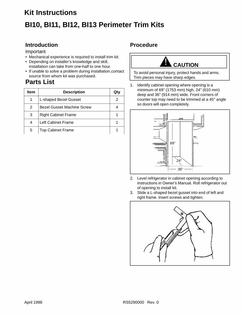
April 1998 RS5290000 Rev. 0
Kit Instructions
IntroductionImportant• Mechanical experience is required to install trim kit.• Depending on installer’s knowledge and skill,
installation can take from one-half to one hour.• If unable to solve a problem during installation,contact
source from whom kit was purchased.
Parts List
Procedure
! CAUTIONTo avoid personal injury, protect hands and arms.Trim pieces may have sharp edges.
1. Identify cabinet opening where opening is aminimum of 69" (1753 mm) high, 24" (610 mm)deep and 36" (914 mm) wide. Front corners ofcounter top may need to be trimmed at a 45° angleso doors will open completely.
36"
69"
24"
2. Level refrigerator in cabinet opening according toinstructions in Owner's Manual. Roll refrigerator outof opening to install kit.
3. Slide a L-shaped bezel gusset into end of left andright frame. Insert screws and tighten.
Item Description Qty
1 L-shaped Bezel Gusset 2
2 Bezel Gusset Machine Screw 4
3 Right Cabinet Frame 1
4 Left Cabinet Frame 1
5 Top Cabinet Frame 1
BI10, BI11, BI12, BI13 Perimeter Trim Kits
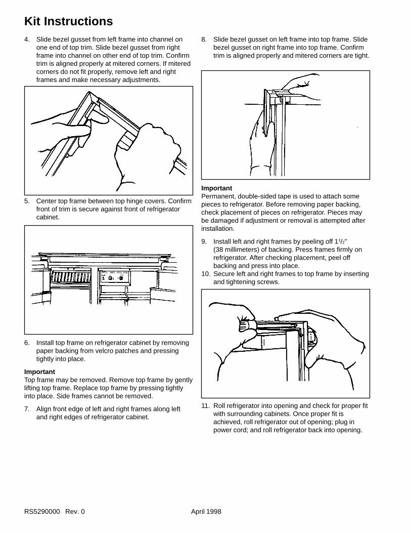
RS5290000 Rev. 0 April 1998
Kit Instructions4. Slide bezel gusset from left frame into channel on
one end of top trim. Slide bezel gusset from rightframe into channel on other end of top trim. Confirmtrim is aligned properly at mitered corners. If miteredcorners do not fit properly, remove left and rightframes and make necessary adjustments.
5. Center top frame between top hinge covers. Confirmfront of trim is secure against front of refrigeratorcabinet.
6. Install top frame on refrigerator cabinet by removingpaper backing from velcro patches and pressingtightly into place.
ImportantTop frame may be removed. Remove top frame by gentlylifting top frame. Replace top frame by pressing tightlyinto place. Side frames cannot be removed.
7. Align front edge of left and right frames along leftand right edges of refrigerator cabinet.
8. Slide bezel gusset on left frame into top frame. Slidebezel gusset on right frame into top frame. Confirmtrim is aligned properly and mitered corners are tight.
11. Roll refrigerator into opening and check for proper fitwith surrounding cabinets. Once proper fit isachieved, roll refrigerator out of opening; plug inpower cord; and roll refrigerator back into opening.
ImportantPermanent, double-sided tape is used to attach somepieces to refrigerator. Before removing paper backing,check placement of pieces on refrigerator. Pieces maybe damaged if adjustment or removal is attempted afterinstallation.
9. Install left and right frames by peeling off 11/2"(38 millimeters) of backing. Press frames firmly onrefrigerator. After checking placement, peel offbacking and press into place.
10. Secure left and right frames to top frame by insertingand tightening screws.