Embed Size (px)
Citation preview

BH Fitness Service and Repair Manual:S1Ti, T300i, T500i
S1Ti
T300i
T500i
1

S1Ti Service Manual
Table of Contents
1. Warnings…………………………………….............pg. 3
2. Current Compensation Procedure.……….............pg. 4
3. Test Mode……………………………………...........pg. 6
4. Calibration Procedure……………………...............pg. 7
5. No Display……………………………………..........pg. 9
6. E1 Error……………………..…………….…………pg. 16
7. E2 Error………………………………………………pg. 18
8. E3 Error.……………………………………………..pg. 21
9. E4 Error………………………………………...........pg. 24
10. E6 Error………………………………………………pg. 27
11. E8 Error………………………………………………pg. 34
12. Table of Contents: Repair and Replacements…..pg. 35
2

Warnings pageIn these pages, you will experience 3 levels of warnings about the procedures you are about to perform. Understand the level of danger each sign signifies and use the proper amount of caution with each procedure.
When you see this sign, we will be performing a test that requires measuring line voltage or a similar voltage that could cause serious injury or death. Take precautions that include setting probes securely before applying line voltage, not touching bare energized terminals or parts of the circuit boards, checking insulation on wires before handling them, properly setting and maintaining test equipment, and following the procedure precisely. Never put yourself at risk regardless of how you interpret the instructions. Call BH Support at
866-325-2339 if you have any questions or feel unsafe before trying any of the instructions.
When you see this sign, we will be performing a procedure with the parts of the unit moving. Take precautions that include: avoiding pinch points; keeping hair, jewelry, clothing, probe leads, tools and body parts out of possible entanglements. Serious injury could occur if precautions are not taken. Call BH Support at 866-325-2339 if you have any questions or feel unsafe before trying any of the instructions.
When you see this sign, we will be performing a procedure that may be a little challenging. An example would be laying over the treadmill to work underneath. Improper layover of the treadmill could damage furniture in the customer’s home, scratch the floor, scratch the treadmill or cause the unit to fall on you. Use your good technician judgment when you perform these procedures in a way that is safe for you, the unit and the customer’s home.
3

S1Ti Current Compensation Procedure
This procedure can help you smooth out motor operation after replacing a new DC motor or controller or on an older DC motor or controller not working properly.
When the computer shows “ENTER WEIGHT”, remove the safety key and
press and hold and while replacing the safety key. The computer will show “EN4 CURRENT COMPENSATE VALUE”.
Press to see the current value. The default value is 25.
To reduce sluggishness or bogging down,
Increase the value by 5 counts using and then press to save
the change. Press 2 times until the computer resets to the “ENTER WEIGHT” screen.
Start the unit and walk on the running belt at various speeds to see if the result is acceptable. Repeat these steps if necessary.
Turning up the value too high will make the running belt surge in speed. Reduce the value to eliminate surging.
To reduce surging in speed,
Decrease the value by 5 counts using and then press to save
the change. Press 2 times until the computer resets to the “ENTER WEIGHT” screen.
Start the unit and walk on the running belt at various speeds to see if the result is acceptable. Repeat these steps if necessary.
4

Turning the value too low will cause the running belt to be sluggish and bog down too much under load. Increase the value to eliminate bogging.
5

S1Ti Test Mode
Enter this mode to check software version, get miles and hours, perform a display test or key test.
To enter test mode, turn on the power switch, remove the safety key and press and hold
and simultaneously while placing the safety key.
The computer shows:
The software version is scrolling across the bottom. The mileage is in the center and the hours are in the upper left.
Press , the computer shows:
Press and the computer will go through a scrolling display
test. Press to end the test.
Press , the computer shows:
Press to start the test. The computer will display “PRESS ALL KEYS”. When you press each key, its name will appear in the display. After all keys are pressed, the display will show “PASS”
Press and the computer shows
Press and the computer will show “WAIT” and then give a series of beeps. When the screen returns to “CLR EEP”, the eeprom has been cleared and the mileage and hours are reset.
6

Press to exit test mode.
S1Ti Calibration Procedure
From the “ENTER WEIGHT” screen, remove the safety key. Press and
hold the and simultaneously while replacing the safety key
until the computer shows
Press and computer will show If this value is set inaccurately the speed of the treadmill will be off.
Press and computer will show If this value is set too low, the motor may fail prematurely from high
torque requirements.
Press and computer will show If this value is set inaccurately, the controller may be unable to reach
the requested speed.
7
will select English units
will select metric units
If the value is not 60.00,
use the or to set to 60.00
If the value is not 1.0,
use the to set to 1.0
If the value is not 10.0, use
the or to set to 10.0

Press and computer will show If this value is not set correctly, the incline will be inaccurate and may
show errors.
Press and computer will show
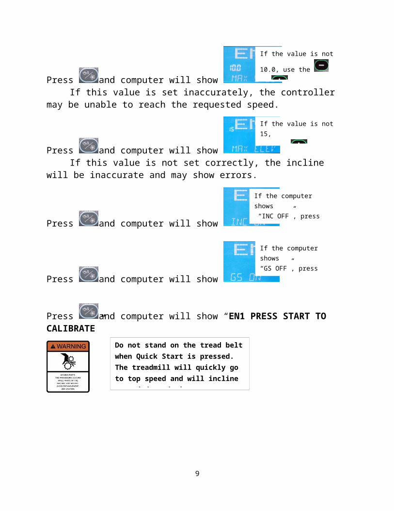
Press and computer will show
Press and computer will show “EN1 PRESS START TO CALIBRATE”
Press and computer will display “CALIBRATE” while calibrating.
If the calibration is successful, the computer will reset to the “ENTER WEIGHT” screen.
If calibration cannot be completed, an error code will be displayed.
8
If the value is not 15,
use the to set to 15
If the computer shows
“INC OFF”, press to turn the incline on
If the computer shows
“GS OFF”, press to turn the GS on
Do not stand on the tread belt when Quick Start is pressed. The treadmill will quickly go to top speed and will incline up and down during calibration.
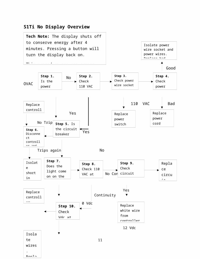
S1Ti No Display Overview
Good
No 0VAC OVAC
110 VAC Bad
Yes 110 VAC
No Trip
Yes
Trips again No
No No VAC No Cont.
Yes Yes Continuity
0 Vdc
12 Vdc
Bad Good
9
Tech Note: The display shuts off to conserve energy after 4 minutes. Pressing a button will turn the display back on.
This procedure assumes proper power supplied to the unit. Check that first.
Step 1. Is the power switch lit when on?
Step 2. Check110 VAC at power switch
Step 3. Check power wire socket and wires
Step 4. Check power cord
Isolate power wire socket and power wires. Replace bad part.
Replace controller
Step 6. Disconnect controller and check for trip.
Step 5. Is the circuit breaker tripped?
Replace power switch
Replace power cord
Isolate short in power wires
Step 7. Does the light come on on the controller?
Step 8. Check 110 VAC at controller
Step 9. Check circuit breaker/wires
Replace circuit breaker
Replace controller
Step 10. Check Vdc at controller
Replace white wire from controller to power switch
Step 11. Check continuity on control wire up and lower
Replace computer
Isolate wires. Replace bad section.

S1Ti No DisplayStep 1: Visually check for power switch light
Turn the power switch on and if 110 VAC is present at the switch, the light in the center of the switch should be lit.
Step 2: Check for 110 VAC at the power switch
Unplug the power cord from the unit . Set the voltmeter for VAC. Place 1 lead in the black wire and one lead in white wire on top of power switch as shown. Plug power cord in and turn power switch on.
10
No light. Go to Step 2
Yes the switch is lit, go to Step 5.
Less than 110 VAC go to step 3
110 VAC present, go to Step 5
S1Ti No DisplayStep 3: Check power wire socket and wires
Unplug the power cord from the unit . Set the voltmeter for VAC.
Detach black and white power wires from bottom of power switch. Place 1 lead in the black
wire and one lead in white wire as shown. Plug power cord in.
Step 4: Check power cord
Unplug the power cord from the unit and the outlet. Set the voltmeter for Check each prong at both ends. Each should be less than .5
11
Less than 110 VAC go to Step 4
110 VAC present, replace power switch
Greater than .5 Ω on any lead – replace power cord
Continuity less than .5 Ω on all three leads – check each wire on power wire socket and each terminal on the power wire socket. Replace defective part

S1Ti No Display Step 5: Check for circuit breaker trip
Visually inspect circuit breaker for being popped out. Unplug the power cord from the unit. Set the voltmeter for . Place 1 lead on each terminal of the circuit breaker.The circuit breaker should measure less than 1 if not tripped.
Step 6: Isolate source of circuit breaker trip
Turn off the power switch and unplug the power cordWait for the light on the controller to go out.Disconnect the black and white power wires from the controller.Set the wires so the metal ends will not make contact with metal or each other. Plug power cord in and turn power switch on. Check for circuit breaker trip.
12
Circuit breaker is tripped or has no continuity. Go to Step 6
Circuit breaker not tripped, has continuity, go to Step 7

S1Ti No Display Step 7: Visually check light on the controller
With the unit plugged in and turned on, the controller light should be on if 110VAC is present at the controller.
Step 8: Check for 110 VAC at the controller
Turn off the power switch and unplug the power cord from the unit .
Set the voltmeter for VAC. Place 1 lead in the black wire and one lead in white wire as shown. Plug power cord in and turn power switch on.
13
Controller light
Circuit breaker did not trip. Replace controller
Circuit breaker trips again, unplug unit and find short in power wires
The controller light is not on. Go to step 8
The controller light is on, go to Step 10
No VAC at controller. Go to Step 9

S1Ti No Display Step 9: Check circuit breaker and wires
Turn off the power switch and unplug the power cord from the unit . Set the voltmeter for . Place 1 lead in the black wire going to the circuit breaker and one lead into the black wire going from the circuit breaker as shownThe voltmeter should read around .3
Step 10: Check for 12 VDC at the power switch
Set the voltmeter for VDC. On the control wire lower, note pins 2 and 5 where the orange and black wires are located. Place one meter lead on pin 2 and one on pin 5. You may have to remove
some hot glue to get access to the metal pins. Check for 12 VDC.
14
110 VAC at controller, go to Step 10
Greater than .3 Ω or OL, check each of wires and circuit breaker and replace defective part
.3 Ω or less, replace the white wire from the controller to the power switch

S1Ti No DisplayStep 11: Check resistance on control wire up and lower
Turn the power switch off and unplug the power cord. Set the voltmeter for Disconnect the control wire at the top and bottom. Using the metal pads on the control wire connector check each wire at the top and bottom. The resistance should be less than .5 You may need assistance to do this.
15
12 VDC present, go to Step 11
0 VDC or less than 10 VDC, replace controller
Less than .5 Ω on all wires, replace computer
Greater than .5 Ω on any of the wires, check individual control wire sections. Replace defective section

S1Ti E1 error overview
This error is a communication error between the computer and the controller. Loss of connection on the control wire up or lower will cause this error.
Good Good
Bad Bad
16
Step 1. Check continuity on control wire up and lower
Step 2. Check pins of controller and computer
Replace computer and controller
Check up and lower section. Replace defective part
Straighten pins. If not fixed, replace component.

S1Ti E1 error
Step 1: Check resistance on control wire up and lower
Turn the power switch off and unplug the power cord. Set the voltmeter for Disconnect the control wire at the top and bottom. Using the metal pads on the control wire connector check each wire at the top and bottom. The resistance should be less than .5 You may need assistance to do this.
Step 2: Check control wire connection pins on controller and computer
Turn the power switch off and unplug the power cord. Disconnect the control wire at the top and bottom. Check the connectors at the controller and computer. All the pins of the connectors should be straight and mate well with the connectors on the wires.
17
Resistance greater than .5on any of the wires: isolate which part of control wire is defective by performing the test on each part. Replace defective control wire.
Wires good. Go to Step 2
Bad pins found. Straighten pins if possible. If the connector is too damaged to take control wire, replace that component.
All pins good, replace controller and computer.

S1Ti E2 Error Overview
This error is predominantly seen in calibration mode when the treadmill is determining speed values based on information from the speed sensor. In normal mode, the treadmill can run on saved values for speed control.
Bad
Good
E2 Good
Bad
18
Step 1. Check sensor
Replace sensor
Step 2. Check sensor gap and calibrate
Step 3. Check continuity on control wire
Replace controller, computer
Isolate control wires. Replace defective wire.

S1Ti E2 Error
Step 1: Check Sensor
Turn the power switch off and unplug the power cord. Set the voltmeter for ΩDisconnect the sensor wire from controller. With the magnet in front of the sensor, the resistance should be less than .5 ΩWith the magnet not in front of the sensor, the resistance should be less than OL.
Step 2: Check Sensor Gap
The sensor should be pointed toward the magnet on the front roller. The sensor should be less than 3/8” away from magnet.
If sensor is turned away or at wrong angle, loosen screw and pivot sensor to correct angle.
If sensor is too far from magnet, cut hot glue and adjust sensor closer to magnet. Reglue if needed. Perform calibration as per S1Ti calibration procedure.
19
Voltmeter shows OL or less than .5 Ω all the time. Replace sensor
Sensor tests good, go to Step 2
E2 in calibration, go to Step 3

S1Ti E2 Error
Step 3. Check resistance on control wire up and lower
Turn the power switch off and unplug the power cord. Set the voltmeter for ΩDisconnect the control wire at the top and bottom. Using the metal pads on the control wire connector check each wire at the top and bottom. The resistance should be less than .5 Ω You may need assistance to do this.
20
Resistance greater than .5on any of the wires: isolate which part of control wire is defective by performing the test on each part. Replace defective control wire.
Wires good. Replace computer and controller

S1Ti E3 Error Overview
E3 is a current over limit error. This error can be caused by excessive friction in the belt and desk or a DC motor problem.
Shortly after start Good w/ no load
Into workout Bad
Low
High
Stays low
Remains high
21
Step 1. When does I limit light come on?
Step 2. Check DC motor brushes
Replace DC motor and controller
Step 3. Perform Amp draw
Reface motor brush. Check again. Replace DC motor if E3
Lube and test unit
Give customer lube schedule
Replace running belt/board

S1Ti E3 Error Step 1: Visually check when the I limit light comes on
The I limit light is located on the controller as shown. Remove the motor cover and note when the I limit light starts to light. Does it come on at higher speeds with no load? Does is come on only with someone on the belt after some time?
Step 2: Check DC motor brushes
Turn off power switch and disconnect power cord.Remove motor cover.Unscrew black motor cover door with standard screwdriver.Pull out motor brushes with spring. Check faces of motor brushes and wire connection.
The motor brush face should be evenly worn and the wire connection not be loose at either end.There should be no areas of black from arcing and no chips or cracks.
22
The light comes on with no load. Go to step 2 The light comes on with
someone on the belt after some time. Go to step 4
DC motor brush faces and wires check good – Replace DC motor and controller
DC motor brush faces bad – sand out rough areas with light grit sandpaper keeping curved shape and reinsert. If I limit light remains, replace DC motor.If wire connection to motor brush bad, replace DC motor.
I limit light

S1Ti E3 Error
Step 3: Perform Amp draw
Set voltmeter to Amp AC Clamp voltmeter around either black or white power wire.Set speed at 2.5, check amps without load and while walking on the belt.Values should be: without load – 1A with load – 3ASet speed at 5 mph, check amps without load and while walking on the belt.Values should be: without load – 2A with load – 4-5A
23
If values are higher than expected, lube the running belt with silicone lube and test for 10 – 15 minutes. If amp draw gradually increases, replace running belt and running board. If amp draw stays steady, advise customer about lube frequency.
Values are as expected, go to Step 2

S1Ti E4 error overview
This error is a speed command error. When the computer sends the command for speed, it looks for a connection to the controller and through to the DC motor. Any break in this chain creates an E4.
Bad
Good
Bad
Good
Over15 Ω or OL
Around 2 Ω
24
Step 1. Check continuity on control wire up and lower especially pin 1 (yellow)
Check individual control wires. Replace bad control wire
Step 2. Check connection of motor wires to controller
Re-crimp wires and reconnect
Step 3. Check continuity through motor wires
Replace DC motor
Replace controller and computer

S1Ti E4 ErrorStep 1: Check resistance on control wire up and lower
Turn the power switch off and unplug the power cord. Set the voltmeter for Disconnect the control wire at the top and bottom. Using the metal pads on the control wire connector check each wire at the top and bottom especially the yellow wire on pin 1. The resistance should be less than .5 You may need assistance to do this.
Step 2: Check connection of DC motor wires to controller
Turn off power switch and disconnect power cord. When controller light goes out, check the DC motor wire connections to the controller by tugging to check for good mechanical connection of the wire to the connector and the connector to the controller spade.
25
Good- Go to Step 2
Bad connection – crimp on new connectors. If unable to make good connection, replace defective component
Good connection, Go to step 3
Greater than .5 Ω on any of the wires, check individual control wire sections. Replace defective section

Step 3: Check resistance through DC motor wires
With power cord still disconnected, disconnect the DC motor wires checked above from controller.Set voltmeter to Ω. Place 1 lead in each wire. The resistance should be around 2 Ω.
26
Resistance is around 10-15 Ω or OL. Replace DC motor.
Resistance is around 2 Ω Replace controller, computer

S1Ti E6 Error Overview
This error is related to the incline system. It is a general purpose error that can be caused by loss of communication to the incline motor, lack of movement, or out of position.
Yes Good Good Good
No Bad Bad Bad
Yes
No Bad
Good
0 VAC
110 VAC
E6
27
Step 1. Does incline drive up after pressing
then E6?
Step 2. Check values on small incline wires
Step 3. Check connection of small incline wires
Step 4. Check continuity on control wire up, lower
Replace controller, computer perform S1Ti calibration
Isolate/replace damaged section
Replace incline motor
Step 5. Does the incline move commanded before E6?
Step 6. Reset incline motor and perform S1Ti calibration
Step 8. Check VAC to incline motor
Replace controller
Step 7. Check continuity on control wire up, lower
Isolate/replace damaged section
Replace controller, computer
Step 9. Reset incline motor and perform S1Ti calibration
Replace incline motor
E6
No reset

S1Ti E6 Error Step 1: Check for incline movement up before E6
Verify that the treadmill is not at top incline. If in cline is already at highest incline, go to step 6.
Turn the unit on. Press .Observe whether the incline goes up uncommanded then the E6 is appears.This movement typically indicates loss of signal from incline position sensor.
Step 2: Check values on small incline wires
Turn off power switch and disconnect power cord. Disconnect small incline wires from controller. Set voltmeter to Ω.
At 0% incline across the red and white wires approx. 1000 Ω15% incline across the red and white wires 7590 Ω approx.
28
Incline goes up, Go to Step 2
Incline does not go up before E6. Go to step 6
Values good, go to Step 3
0L on red and white, replace incline motor
Incline values not 0L but not correct, go to Step 6

S1Ti E6 Error Step 3: Check connection of small incline wires
Using small incline wires from above, disconnect small incline wires from controller. Check all controller pins are straight and mate well with incline wires.
Step 4: Check continuity on control wire up, lower
Turn the power switch off and unplug the power cord. Set the voltmeter for Disconnect the control wire at the top and bottom. Using the metal pads on the control wire connector check each wire at the top and bottom. The resistance should be less than .5 You may need assistance to do this.
29
Good connection, Go to Step 4
Pins bent on controller - straightenIf controller connector broken – replace controllerIf incline motors wires connector broken – replace incline motor
Less than .5 Ω on all wires, Replace controller and computer and perform S1Ti calibration
Greater than .5 Ω on any of the wires, check individual control wire sections. Replace defective section

S1Ti E6 ErrorStep 5: Check for commanded incline movement before E6.
Turn the unit on, place the safety key and press Can the incline be commanded to move up or down and incline does move before E6 is displayed?
Step 6: Reset incline motor and perform S1Ti calibration
Turn off unit at power switch and disconnect power cord
Fold the treadmill up and carefully lay the unit over on its side.
Remove the two R pins and take out the two incline bases. Test to see if incline motor shaft casing is free to spin or is jammed against incline motor. If jammed, free the casing using a channel locks.
Turn the incline motor shaft casing until 3/8” of incline motor shaft is showing.
30
Yes, incline moves as commanded then E6, go to Step 6
No incline movement, go to Step 8
Incline motor shaft casing Motor shaft

S1Ti E6 Error Step 6: Reset incline motor and perform S1Ti calibration
Reconnect the power cord and turn the treadmill on.
Press . The incline motor should drive to the zero position. If it does not move, it is already set at zero.
Check values on small incline wires as shown in step 2 to verify it is at the values for 0%.
Perform S1Ti calibration procedure.
Step 7: Check continuity on control wire up and lower
Turn the power switch off and unplug the power cord. Set the voltmeter for Disconnect the control wire at the top and bottom. Using the metal pads on the control wire connector check each wire at the top and bottom. The resistance should be less than .5 You may need assistance to do this.
S1Ti E6 Error
31
E6 continues, go to Step 7
Unable to reset incline motor or have small incline motor wires values reset, replace incline motor
Less than .5 Ω on all wires, Replace controller and computer and perform S1Ti calibration
Greater than .5 Ω on any of the wires, check individual control wire sections. Replace defective section

Step 8: Check VAC to incline motorTurn the unit on. Set voltmeter to VAC.Insert voltmeter leads in black and white wire slots on incline motor power wire connector as shown.
Press . Check for 120 VAC.Insert voltmeter leads in red and white wire slots on incline motor power wire connector as shown. Press
. Check for 120 VAC.
S1Ti E6 Error Step 9: Reset incline motor and perform S1Ti calibration If the incline motor shaft casing has jammed against the incline motor, the incline motor may be getting AC voltage to move but may be unable to overcome the jam.Turn off unit at power switch and disconnect power cord
Fold the treadmill up and carefully lay the unit over on its side.
Remove the two R pins and take out the two incline bases. Test to see if incline motor shaft casing is free to spin or is jammed against incline motor. If jammed, free the casing using a channel locks. S1Ti E6 Error Step 9: Reset incline motor and perform S1Ti calibration continued
32
110 VAC on up and down, go to step 9 0 VAC
Replace controller
Incline motor shaft casing Motor shaft

Turn the incline motor shaft casing until 3/8” of incline motor shaft is showing.
Reconnect the power cord and turn the treadmill on.
Press . The incline motor should drive to the zero position. If it does not move, it is already set at zero.
Check values on small incline wires as shown in step 2 to verify it is at the values for 0%.
Perform S1Ti calibration procedure.
33
E6 again. Replace incline motor

S1Ti E8 Error Overview
E8 is a software error. The computer has failed a self-diagnostic test. Try to clear EEP and if no help, replace the computer.
E8
34
Step 1. Go to S1Ti Test Mode procedure to CLR EEP
Replace computer

S1Ti Repair and Replacement Procedures
13. Controller ………………………………………………….pg 35
14. DC Motor ………………………………………………….pg 38
15. Belt 230J8…………………………………………………pg. 43
16. Incline motor………………………………………………pg. 47
17. Front roller…………………………………………………pg. 51
18. Rear roller………………………………………………….pg 56
19. Running belt/running board……………………………..pg. 57
20. Computer/ Keyboard 20 key……………………………pg. 63
35

S1Ti Controller Replacement Procedure
Tools required: #2 Philips screwdriver, heat sink compound- Dow Corning 340 recommended
36
Step 3. Remove 2 screws from the base of the controller using phillips screwdriver.
Step 1. Turn off unit at power switch and disconnect power cord.
Step 2. Remove motor cover by taking out 5 screws with phillips screwdriver then lift off motor cover
Step 4. Make sure the light is off on the controller before disconnecting all wires and removing the controller.
controller light

S1Ti Controller Replacement Procedure
Figure 1 Controller wire connections
37
Step 6. Set the new controller into place and connect all the wires according to Figure 1.
Incline motor small wires
Control wire lowerSensor wires
M+ (red) from DC motor
M- (black) from DC motor
Incline motor power wires
AC in (black) from power cord
Neutral (white) from power cord
Step 5. Apply heat sink compound to the base of the new controller as shown.

S1Ti Controller Replacement Procedure
38
Step 7. Replace the screws in the controller base with a Phillips screwdriver. Be sure to use the green screw for the ground lead.
Step 8. Replace motor cover and 5 screws using Phillips screwdriver.
Step 9. Reconnect power cord and turn on at power switch
Step 10. Calibrate speed and incline as shown in S1Ti Calibration Procedure.
Step 11. If you experience the belt slowing under load too much or having a surging feel, adjust the current compensation as shown in the S1Ti Current Compensation procedure

S1Ti DC Motor Replacement ProcedureTools required: #2 Philips screwdriver, ratchet with 8mm allen socket and extension, 6mm allen socket
39
Step 3. Cut the wire ties on the red and black motor wires and remove the ground lead by unscrewing the green controller screw.
Step 1. Turn off unit at power switch and disconnect power cord.
Step 2. Remove motor cover by taking out 5 screws with Philips screwdriver and lifting off motor cover
Tech TipIf the belt 230J8 tension is good, you can use the current DC motor bracket setting as a guide to install the replacement DC motor. Scratch a line on the motor pan where the motor bracket sits and set the replacement DC motor bracket back to that spot before testing belt 230J8 tension.

S1Ti DC Motor Replacement Procedure
Figure 1 Controller light and wire connections
40
Step 4. Make sure the light is off on the controller before disconnecting M+ and M- wires from the controller. See figure 1.
controller light
M+ (red) from DC motor
M- (black) from DC motor
Step 5. Reduce the belt 230J8 tension by loosening the 4 DC motor bracket hex screws using an 8mm allen. Then remove the hex screw that pulls the motor bracket forward using a 6mm allen. Push the DC motor toward the running belt.
Step 6. Remove the 4 DC motor bracket hex screws. Lift the belt 230J8 off the DC motor pulley and lift out the DC motor.
Motor bracket hex screws
Hex screw that pulls the motor bracket

S1Ti DC Motor Replacement Procedure
S1Ti DC Motor Replacement Procedure
41
Step 9. Set the new DC motor in place and thread in but do not tighten the 4 motor bracket hex screws and the hex screw that pulls the motor bracket forward.
Step 7. Remove the motor bracket from the DC Motor and transfer it to the new DC motor using a 6mm allen socket.
Step 8. Remove the choke from the DC Motor wires and transfer it to the new DC motor wires by wrapping as shown.
Step 10. Set the belt 230J8 in place on the DC motor pulley. Align the belt by measuring from the frame at the front roller and the DC motor pulley.
Step 11. Tension the belt 230J8 by tightening the hex screw that pulls the motor bracket forward. Set the tension until you can only push down 1/8” in the center of the belt with two fingers as shown.
Hex screw that pulls the motor bracket
Motor bracket hex screws

42
Step 15. Replace motor cover and 5 screws using Phillips screwdriver.
Step 13. Replace the wire ties on the red and black motor wires and reinstall the ground lead on the green controller screw.
Step 12. Tighten the 4 motor bracket hex screws using an 8mm allen
Step 14. Connect new DC motor wires to controller as shown in Figure 1 above

43
Step 16. Reconnect power cord and turn on at power switch
Step 17. Calibrate speed and incline as shown in S1Ti Calibration Procedure.
Step 18. If you experience the belt slowing under load too much or having a surging feel, adjust the current compensation as shown in the S1Ti Current Compensation Procedure

S1Ti Belt 230J8 Replacement Procedure
Tools required: #2 Phillips screwdriver, ratchet with 8mm allen socket and extension, 6mm allen wrench, 12 mm wrench
44
Step 1. Turn off unit at power switch and disconnect power cord.
Step 2. Remove motor cover by taking out 5 screws with Philips screwdriver and lifting off motor cover
Tech TipIf the belt 230J8 tension is good, you can use the current DC motor bracket setting as a guide to install the replacement belt 230J8. Scratch a line on the motor pan where the motor bracket sits and set the DC motor bracket back to that spot before testing belt 230J8 tension. You can mark the bolt side of the front roller position on the frame in similar fashion to save running belt alignment time.
Step 3. Reduce the belt 230J8 tension by loosening the 4 motor bracket hex screws using an 8mm allen and then turning counterclockwise using a 6mm allen the hex screw that pulls the motor bracket forward.
Motor bracket hex screws
Hex screw that pulls the motor bracket

S1Ti Belt 230J8 Replacement Procedure
S1Ti Belt 230J8 Replacement Procedure
45
Step 4. Push the motor toward the running belt and slide the belt 230J8 off the DC motor pulley
Step 5. Reduce the tension on the running belt by turning counterclockwise the rear roller bolts using a 6 mm allen.
Step 6. Remove the front roller bolt using a 6mm allen. Then pull the front roller toward the bolt side until it comes out of the frame hole and there is enough room to remove the belt 230J8. Remove the belt 230J8.
Step 7. Place the new belt 230J8 over the front roller pulley and slide the front roller into the frame hole. Replace the front roller bolt.
Step 8. Slide the belt 230J8 onto the DC motor pulley
Rear Roller bolts
Step 9. Align the belt by measuring from the frame at the front roller and the DC motor pulley.

S1Ti Belt 230J8 Replacement Procedure
46
Step 10. Tension the belt 230J8 by tightening the hex screw that pulls the motor bracket forward. Set the tension until you can only push down 1/8” in the center of the belt with two fingers as shown.
Step 13. Check the alignment of the running belt and adjust as needed by tightening or loosening the front roller bolt. When set, tighten front roller bolt jam nut
Step 12. Restore the tension on the running belt by turning clockwise the rear roller bolts using a 6mm allen.
Reconnect power cord and turn on at power switch. Press
to start unit.
Continue to turn the rear roller bolts clockwise ¼ turn at a time until the running belt does not slip as you walk or run on it.
Step 11. Tighten the 4 motor bracket hex screws using an 8mm allen
Motor bracket hex screws
Hex screw that pulls the motor bracket
Rear Roller bolts

S1Ti Incline Motor Replacement ProcedureTools required: Phillips screwdriver, 8 mm socket/ratchet, 17 mm wrench, needle nose pliers
47
Step 13. Check the alignment of the running belt and adjust as needed by tightening or loosening the front roller bolt. When set, tighten front roller bolt jam nut
Step 14. Replace motor cover and 5 screws using a Phillips screwdriver

48
Step 1. Turn off unit at power switch and disconnect power cord.

S1Ti Incline Motor Replacement Procedure
49
Step 2. Remove the motor cover by taking out the 5 screws.
Step 3 Disconnect the incline motor wires from the controller and remove the ground screw using the Phillips screwdriver.
Step 4 Fold the treadmill up and carefully lay the unit over on its side.
Step 5 Remove the bolt and nut from the top of the incline motor using an 8 mm allen and 17 mm wrench.
Incline motor power wires
Incline motor small wires
Incline motor ground screw

S1Ti Incline Motor Replacement Procedure
50
Step 6 Remove the two R pins and take out the two incline bases. Lift out the incline motor.
Step 7 Connect the wires for the new incline motor as shown above and install the ground wire with the ground screw.
Step 8 Set the incline motor on the frame as shown
Step 9 Reconnect the power cord and turn the treadmill on.
Press .
The incline motor should drive to the zero position. If it does not move, it is already set at zero.
Step 10. Turn off unit at power switch and disconnect power cord.
Step 11. Turn the incline motor shaft casing until 3/8” of incline motor shaft is showing.
Step 12 Replace the incline motor and install the nut and bolt at the top of the incline motor.Be sure to replace the two plastic washers.
Incline motor shaft casing Motor shaft
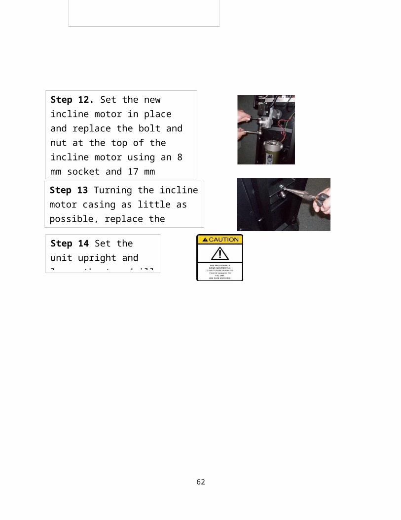
Step 12. Set the new incline motor in place and replace the bolt and nut at the top of the incline motor using an 8 mm socket and 17 mm wrench. Be sure to transfer the two plastic washers from the old

51
Step 13 Turning the incline motor casing as little as possible, replace the incline bases and R pins
Step 14 Set the unit upright and lower the treadmill base
Step 12. Set the new incline motor in place and replace the bolt and nut at the top of the incline motor using an 8 mm socket and 17 mm wrench. Be sure to transfer the two plastic washers from the old

52
Step 15 Reconnect the power and turn the unit on. Calibrate the treadmill as per the S1Ti Calibration Procedure.
Step 16 Check that the unit is at zero by measuring at the front of the unit. The main frame should be approx, 4 ½ “off the ground
Step 17 Replace motor cover with five screws.

S1Ti Front Roller Replacement Procedure
Tools required: #2 Philips screwdriver, ratchet with 8mm allen socket and extension, 6mm allen wrench, 12mm wrench
53
Step 1. Turn off unit at power switch and disconnect power cord.
Step 2. Remove motor cover by taking out 5 screws with Philips screwdriver and lifting off motor cover
Tech TipIf the belt 230J8 tension is good, you can use the current DC motor bracket setting as a guide to install the replacement belt 230J8. Scratch a line on the motor pan where the motor bracket sits and set the DC motor bracket back to that spot before testing belt 230J8 tension. You can mark the bolt side of the front roller position on the frame in similar fashion to save running belt alignment time.
Step 3. Reduce the belt 230J8 tension by loosening the 4 motor bracket hex screws using an 8mm allen and then turning counterclockwise using a 6mm allen the hex screw that pulls the motor bracket forward.
Motor bracket hex screws
Hex screw that pulls the motor bracket

S1Ti Front Roller Replacement Procedure
S1Ti Front Roller Replacement Procedure
54
Step 4. Push the motor toward the running belt and slide the belt 230J8 off the DC motor pulley
Step 5. Reduce the tension on the running belt by turning counterclockwise the rear roller bolts using a 6 mm allen.
Step 6. Remove the front roller bolt using a 6mm allen. Then pull the front roller toward the bolt side until it comes out of the frame hole. Slip the belt 230J8 off the front roller pulley and slide the front roller out of the running belt.
Step 7. Place the belt 230J8 over the front roller pulley and slide the new front roller into the frame hole. Replace the front roller bolt.
Step 8. Slide the belt 230J8 onto the DC motor pulley
Rear Roller bolts
Step 9. Align the belt by measuring from the frame at the front roller and the DC motor pulley.

S1Ti Front Roller Replacement Procedure
55
Step 10. Tension the belt 230J8 by tightening the hex screw that pulls the motor bracket forward. Set the tension until you can only push down 1/8” in the center of the belt with two fingers as shown.
Step 13. Check the alignment of the running belt and adjust as needed by tightening or loosening the front roller bolt. When set, tighten front roller bolt jam nut
Step 12. Restore the tension on the running belt by turning clockwise the rear roller bolts using a 6mm allen.
Reconnect power cord and turn on at power switch. Press
to start unit.
Continue to turn the rear roller bolts clockwise ¼ turn at a time until the running belt does not slip as you walk or run on it.
Step 11. Tighten the 4 motor bracket hex screws using an 8mm allen
Motor bracket hex screws
Hex screw that pulls the motor bracket
Rear Roller bolts

S1Ti Rear Roller Replacement ProcedureTools required: Phillips screwdriver, 6 mm socket/ratchet
56
Step 13. Check the alignment of the running belt and adjust as needed by tightening or loosening the front roller bolt. When set, tighten front roller bolt jam nut
Step 14. Replace motor cover and 5 screws using Phillips screwdriver.

57
Step 1. Turn off unit at power switch and disconnect power cord.

S1Ti Rear Roller Replacement Procedure
58
Step 2. Tilt the base of the treadmill up.
Step 3. Remove the 3 screws in each of the rear decorative covers right and left using a Philips screwdriver and remove the covers
Step 4. Remove the screws in the underside of the pedals and lift them off. 7 screws per side, 6 large 1 small
Step 5. Unscrew completely the roller bolts using a 6 mm socket and slide the rear roller out of the running belt.
Step 7. Set the pedals on the deck and replace the screws from the underside
Step 6. Slide in the new rear roller and replace the roller bolts

S1Ti Running Belt/Running Board Replacement ProcedureTools required: Phillips screwdriver, ratchet with 8mm allen socket and extension, 6mm allen socket, 12mm wrench
59
Step 10. Restore the tension on the running belt by turning clockwise the rear roller bolts using a 6mm allen.
Reconnect power cord and turn on at power switch. Press
to start unit.
Continue to turn the rear roller bolts clockwise ¼ turn at a time until the running belt does not slip as you walk or run on it.
Rear Roller bolts
Step 8. Replace the rear decorative covers right and left using a Philips screwdriver to reinstall the screws.
Step 9. Tilt the base of the treadmill down.
Step 1. Turn off unit at power switch and disconnect power cord.

S1Ti Running Belt/Running Board Replacement Procedure
60
Step 2. Tilt the base of the treadmill up.
Step 3. Remove the 3 screws in each of the rear decorative covers right and left using a Philips screwdriver and remove the covers
Step 4. Remove the screws in the underside of the pedals and lift them off. 7 screws per side, 6 large 1 small
Step 5. Unscrew completely the roller bolts using a 6 mm socket and slide the rear roller out of the running belt.
Step 6. Tilt the base of the treadmill down.

S1Ti Running Belt/Running Board Replacement Procedure
61
Step 7. Remove motor cover by taking out 5 screws with Philips screwdriver and lifting off motor cover
Step 8. Reduce the belt 230J8 tension by loosening the 4 motor bracket hex screws using an 8mm allen and then turning counterclockwise using a 6mm allen the hex screw that pulls the motor bracket forward.
Step 9. Push the motor toward the running belt and slide the belt 230J8 off the DC motor pulley
Step 10. Remove the front roller bolt using a 6mm allen. Then pull the front roller toward the bolt side until it comes out of the frame hole. Slip the belt 230J8 off the front roller pulley and slide the front roller out of the running belt.
Motor bracket hex screws
Hex screw that pulls the motor bracket
Step 11. Remove the running belt and running board by taking out the deck hex screws with a 5mm socket and 13mm wrench and lifting out the running belt and running board.
S1Ti Running Belt/Running Board Replacement Procedure
62
Step 12. Transfer running board brackets from old deck to new deck using a Philips screwdriver.
Step 13. Slide the running belt over the running board and install the new running belt and running board using the deck hex screws with a 5mm socket and 13mm wrench
Step 14. Place the belt 230J8 over the front roller pulley and slide the front roller into the frame hole. Replace the front roller bolt and jam nut.
Step 15. Slide the belt 230J8 onto the DC motor pulley
Step 16. Align the belt by measuring from the frame at the front roller and the DC motor pulley.

S1Ti Running Belt/Running Board Replacement Procedure
63
Step 17. Tension the belt 230J8 by tightening the hex screw that pulls the motor bracket forward. Set the tension until you can only push down 1/8” in the center of the belt with two fingers as shown.
Step 18. Tighten the 4 motor bracket hex screws using an 8mm allen
Motor bracket hex screws
Hex screw that pulls the motor bracket
Step 21. Set the pedals on the deck and replace the screws from the underside
Step 20. Slide in the rear roller and replace the roller bolts
Step 19. Tilt the base of the treadmill up.

S1Ti Running Belt/ Running Board Replacement Procedure
64
Step 24. Restore the tension on the running belt by turning clockwise the rear roller bolts using a 6mm allen.
Reconnect power cord and turn on at power switch. Press
to start unit.
Continue to turn the rear roller bolts clockwise ¼ turn at a time until the running belt does not slip as you walk or run on it.
Rear Roller bolts
Step 22. Replace the rear decorative covers right and left using a Philips screwdriver to reinstall the screws.
Step 23. Tilt the base of the treadmill down.
Step 25. Check the alignment of the running belt and adjust as needed by tightening or loosening the front roller bolt. When set, tighten front roller bolt jam nut using the 12mm wrench

S1Ti Computer/ Keyboard 20 Key Replacement Procedure
65
Step 27. Replace motor cover and 5 screws using Phillips screwdriver
Step 26. Press . Turn off power switch and disconnect power cord.
Step 28. Reconnect power cord.
Step 1. Turn off unit at power switch and disconnect power cord.
Step 2. Remove 11 screws from back of computer panel using a Phillips screwdriver and tilt forward the computer panel

S1Ti Computer/ Keyboard 20 Key Replacement Procedure
Figure 1 Computer/ Keyboard 20 key wire connections
66
Step 3. Disconnect wires from computer or keyboard 20 key.
Step 4. Remove screws holding computer or keyboard 20 key and lift out.
Step 5. Install new computer or keyboard 20 key by replacing screws holding the part to the computer panel. Reconnect wires as shown in Figure 1.
Tech Note: Before touching the new computer or keyboard 20 key, ground any static electricity on yourself by touching metal on the frame. Handle the circuit boards by the edge and try to avoid touching the components when possible.
EmptyUSB charging board
Wireless heart beat board
Empty

67
Step 6.Set the computer panel in place and replace 11 screws into back of computer panel using a Phillips screwdriver.
Control wire up
Fan (behind choke)
Safety switch
BT boardHandle switch- speed
Empty
Hand pulse board
Keyboard 20 key
8 pin Sound source board
7 pin
Handle switch- elevation

S1Ti Computer/ Keyboard 20 Key Replacement Procedure
68
Step 8. Calibrate speed and incline as shown in S1Ti Calibration Procedure.
Step 9. If you experience the belt slowing under load too much or having a surging feel, adjust the current compensation as shown in the S1Ti Current Compensation Procedure
Step 10. After replacing the keyboard 20 key, you can test button function by entering the key test in test mode. See the procedure S1Ti Test mode.
Step 7. Reconnect power cord and turn on unit at power switch.