Embed Size (px)
Citation preview
/773 r:.,. ~·~
SVM·7735·1 ·:-;\.
Service Manual For
.~ ROCKWELL ~xial Fan Cooled ~Twin Cylinder Engines
Models 2F-400-6, 2F~440-3; 2F-440-5
• 2-CYCLE ENGINE FUNDAMENTALS
• CARBURETION
• IGNITION
• EXHAUST SYSTEM .
• DISASSEMBLY AND ASSEMBLY INSTRUCTIONS OF BASIC ENGINES INCLUDING RECOIL STARTERS
• • RING GEAR INSTALLATION
• IGNITION TIMING PROCEDURE
• SERVICE TOOLS
....
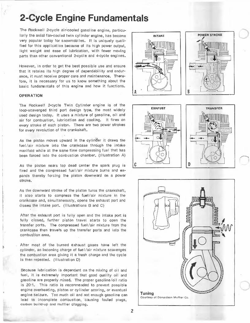
2-Cycle Engine Fundamentals The Rockwell 2-cycle ai r.:.cooled gasoline engine, particu
larly the axial fan-cooled twin cylinder engine, has become very popular today for snowmobiles . It is uniquely qual i
fied for this application because of its high power output, light weight and ease of lubrication, with fewer moving parts than other conventional 2-cycle and 4-cycle engines.
However, in order to get the best possible use and ensure that it retains its high degree of dependability and endur
ance, it must receive proper care and maintenance. Therefore, it is necessary for us to know something about the basic fundamentals of this engine and how it functions.
OPERATION
The Rockwell 2-cycle Twin Cylinder engine is of the loop-scavenged third port design type, the most widely used design today. It uses a mixture of gasoline, oil and air for combustion, lubrication and cooling. It fires on every stroke of each piston. There are two power strokes
for every revolution of the crankshaft.
As the piston moves upward in the cylinder it draws the fuel /ai r mixture into the crankcase through the intake manifold while at the same time compressing fuel that has
been forced into the combustion chamber. (Illustration A)
As the piston nears top dead center the spark plug is fired and the compressed fue I /air mixture burns and expands thereby forcing the piston downward on a power stroke.
As the downward stroke of the piston turns the crankshaft,
it also starts to compress the fuel/air mixture in the crankcase and, simultaneously, opens the exhaust port and closes the intake port. (Illustrations Band C)
After the exhaust port is fully open and the intake port is fully closed, further piston travel starts to open the transfer ports. The compressed fue I I air mixture from the crankcase then travel-s up the transfer ports and into the combustion area.
After most of the burned exhaust gases have left the cylinder, an incoming charge of fuel/air mixture scavenges the combustion area giving it a fresh charge and the cycle is then repeated. (li lustration D)
Because lubrication is dependent on the mixing of oi 1 and fuel, it is extremely important that good quality oil and
gasoline are properl y mixed. The proper gasoline/oi l rati o is 20:1. This ratio is recommended to prevent possible engine overheati ng , piston or cylinder scoring, or eventual engine seizure. Too much oil and not enough gasoline can lead to incomplete combustion, causing fouled plugs, carbon build-up and muffler clogging.
INTAKE
EXHfUST
Tuning Courtesy of Donaldson Muffler Co .
2
TRANSFER
0
c
CARBURETION
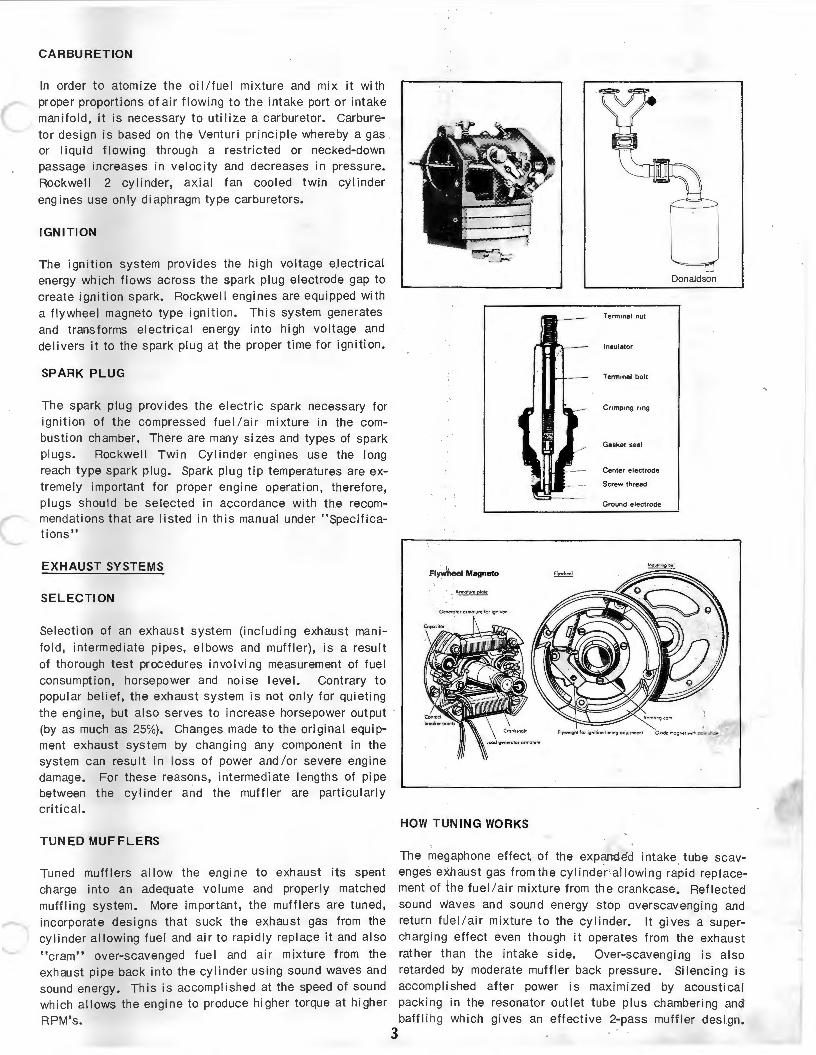
In order to atomize the oil/fuel mixture and mix it with proper proportions of air flowing to the intake port or intake manifold, it is necessary to utilize a carburetor. Carburetor design is based on the Ventur i principle whereby a gas or liquid flowing through a restricted or necked-down passage increases in velocity and decreases in pressure. Rockwell 2 cylinder, axial fan cooled twin cylinder engines use only diaphragm type carburetors.
IGNITION
The ignition system provides the high voltage electrical energy which flows across the spark plug electrode gap to create igni tion spark. Rockwell engines are equipped with a flywheel magneto type ignition. This system generates and transforms electrical energy into high voltage and delivers it to the spark plug at the proper time for ignition.
SPARK PLUG
The spark plug provides the electric spark necessary for ignition of the compressed fuel /a ir mixture in the combustion chamber. There are many sizes and types of spark plugs. Rockwell Twin Cylinder engines use the long reach type spark plug . Spark plug tip temperatures are extremely important for proper engine operation, therefore, plugs should be selected in accordance with th.e recommendations that are listed in this manual under "Specifications"
EXHAUST SYSTEMS
SELECTION
Selection of an exhaust system (including exhaust manifold, intermediate pipes, elbows and muffler), is a result of thorough test procedures involving measurement of fuel consumption, horsepower and noise level. Contrary to popular belief, the exhaust system is not only for quieting the engine, but also serves to increase horsepower output (by as much as 25%). Changes made to the original equipment exhaust system by changing any component in the system can result in loss of power and /or severe engine damage. For these reasons, intermediate lengths of pipe between the cylinder and the muffler are particularl y critical.
TUNED MUFFLERS
Tuned muffl ers allow the engine to exhaust its spent charge into an adequate volume and properly matched muffling system. More important, the mufflers are tuned , incorporate designs th at suck the exhaust gas from the cylinder allowing fuel and air to rapidly repl ace it and also
"cram" over-scavenged fuel and air mixture from the exhaust pipe back into the cylinder using sound waves an d sound energy. Thi s is accompl ished at the speed of sound which allows the engine to produce higher torque at higher
RPM' s. 3
Donaldson
Termanal nut
Insulator
Term.nal bolt
Cnmp1ng nng
Gasket seal
Center electrode
Scr.ew thread
Ground electrode
Fl~heel Magneto
HOW TlJNING WORKS
The megaphone effect of the expanded intake tube scavenges exhaust gas from th e cylinder allowing rapid rep lacement of the fuel/air mixture from the crankcase. Reflected sound Waves and sound energy stop overscavenging and return fue l /a ir mixture t o the cylinder. It gives a supercharging effect even though it operates from the exhaust rather than the intake side. Over-scavenging is also retarded by moderate muffler back pressure. Silencing is accomplished after power is maximized by acoustical packing in the resonator outlet tube plus chambering and baffling which gi ves an effective 2-pass muffler design.
ROCKWELL Twin Cylinder Engines Models 2F -400-6, 2F -440-3, 2F -440-5 Disassembly and Assembly Procedure
DISASSEMBLY
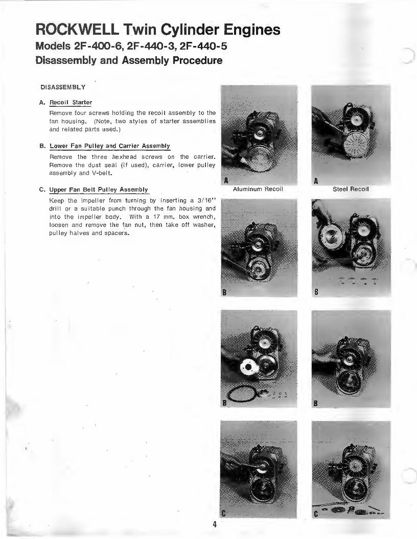
A. Recoi I Starter
Remove four screws holding the recoi I assembly to the fan housing. (Note, two styles of starter assemblies and related parts used.)
B. Lower Fan Pulley and Carrier Assembly
Remove the three hexhead screws on the carrier. Remove the dust seal (if used), carrier, lower pulley assembly and V-belt.
C. Upper Fan Belt Pulley Assembly
Keep the impeller from turning by inserting a 3/16" dri II or a suitable punch through the fan housing and into the impeller body. With a 17 mm. box wrench, loosen and remove the fan nut, then take off washer, pulley halves and spacers.
4
Aluminum Recoil A
Steel Recoil
c
c
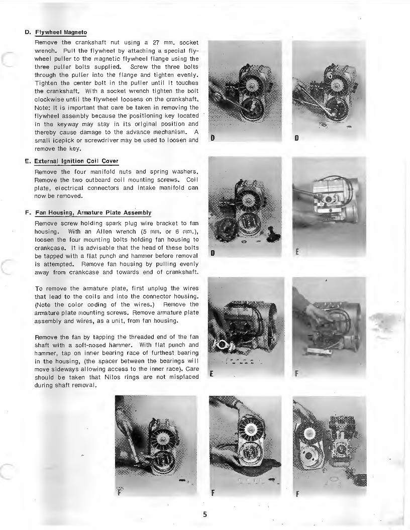
D. Flywheel Magneto
Remove the crankshaft nut using a 27 mm. socket wrench . Pull the flywheel by attaching a special flywheel pu l ler to the magnetic flywheel flange using the three puller bolts supplied. Screw the three bolts through the puller into the f lange and tighten evenly. Tighten the center bolt in the puller until it touches the crankshaJt. With a socket wrench tighten the bolt clockwise unti I the flywheel loosens on the crankshaft.
Note: It is important that care be taken in removing the
flywheel assembly because the positioning key located in the keyway may stay in its original position and thereby cause damage to the advance mechanism. A small icepick or screwdriver may be used to loosen and remove the key.
E. External Ignit ion Coil Cover
Remove the four manifo ld nut s and spring washers. Remove the two outboard coi I mounting screws. Coi I plate, electrical connectors and intake manifold can now be removed.
F. Fan Housing, Armature Plate Assembly
Remove screw holding spark plug wire bracket to fan housing . With an Allen wrench (5 mm. or 6 mm.), loosen the four mounting bolts holding fan housing to
crankcase. It is advisable that the head of these bo lts be tapped with a flat punch and hammer before removal is attempted. Remove fan housing by pulling evenly away from crankcase and towards end of crankshaft .
To remove the armature plate, f irst unplug the wires that I ead to the co i Is and into the connector housing. (Note the color coding of the wires.) Remove the armature plate mounting screws. Remove armature plate assembly and wires, as a unit, from fan housing.
Remove the fan by tapping the threaded end of the fan shaft with a soft-nosed hammer. With flat punch and hammer, tap on inner bearing race of furthest bearing in the housi ng, (the spacer between the bearings wi II move sideways allowing access to the inner race). Care should be taken that Ni los rings are not misplaced during shaft removal.
F
D D
E
E F .
5
ROCKWELL Twin Cylinder Engines Models 2F -400-6, 2F -440-3, 2F -440-5 Disassembly and Assembly Procedure
DISASSEMBLY
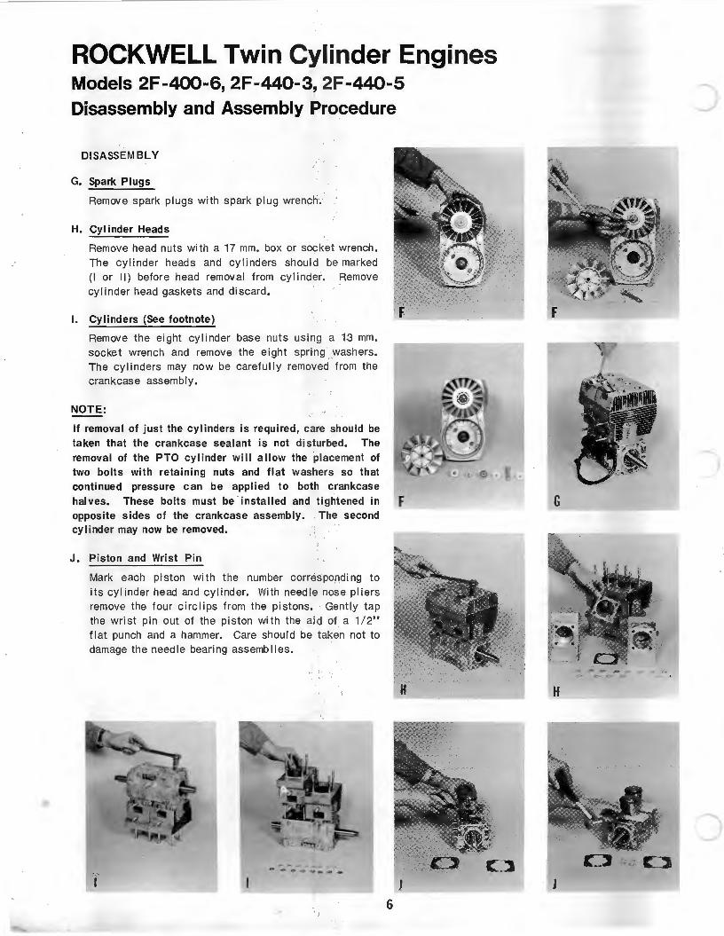
G. Spark Plugs
Remove spark plugs with spark plug wrench.
H. Cylinder Heads
Remove head nuts with a 17 mm. box or socket wrench. The cylinder head s and cylinders shou ld be marked (I or II) before head removal from cylinder. Remove cylinder head gaskets and discard.
I. Cylinders (See footnote)
Remove the eight cylinder base nuts using a 13 mm. socket wrench and remove the e ight spring . washers. The cylinders may now be carefully removed from the crankcase assembly.
NOTE:
If removal of just the cylinders is required, care should be taken that the crankcase sealant is not disturbed. The remova l of the PTO cy linder will a llow the ·placement of two bolts with retaining nuts and flat washers so that continued pressure can be applied to both crankcase
F
halves. These bolts must be installed and tightened in F opposite sides of the crankcase assembly. The second cyli nder may now be removed.
J. Piston and Wrist Pin
Mark each piston with the number corresponding to its cylinder head and cylinder. With needle 'nose pliers remove the four circlips from the pistons. · Gently tap the wri st pin out of the piston with the aid of a 1/2" flat punch and a hammer. Care should be taken not to damage the needle bearing assemblies.
H
J 6
)
G
J
c
c
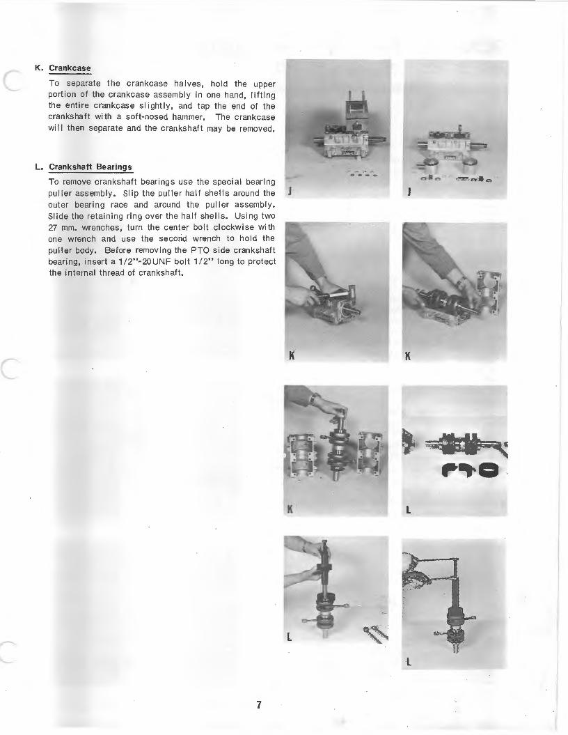
K. Crankcase
To separate the crankcase halves, hold the upper portion of the crankcase assembly in one hand, lifting the entire crankcase slightly, and tap the end of the crankshaft with a soft-nosed hammer. The crankcase wi II then separate and the crankshaft may be removed.
L. Crankshaft Bearings
To remove crankshaft bearings use the special bearing puller assembly. Slip the puller half shells around the J outer bearing race and around the puller assembly. Slide the retaining ring over the half shells. Using two 27 mm. wrenches, turn the center bolt clockwise with one wrench and use the second wrench to hold the puller body. Before removing the PTO side crankshaft bearing, insert a 1/2"-20UNF bolt 1/2" long to protect the internal thread of crankshaft.
7
K
J
, o . L
L
,.•:
ROCKWELL Twin Cylinder Engines Models 2F -400-6, 2F -440-3, 2F -440-5 Disassembly and Assembly Procedure
ASSEMBLY
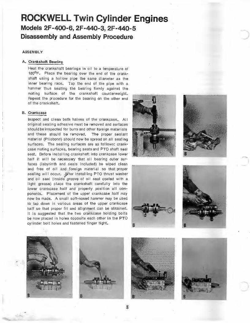
A. Crankshaft Bearing
Heat the crankshaft bearings in oil to a temperature of 180°F. Pl ace the bearing over the end of the crankshaft using a hollow pipe the same diameter as the
inner bearing race. Tap the end of the pipe with a hammer thus seat ing the bearing firmly against the
mating surface of the crankshaft counterweight. Repeat the procedure for the bearing on the other end of the crankshaft.
B. Crankcase
< • •
In spect and c lean both halves of the crankcase~ All original seal ing adhesive must be removed and surfaces shou ld be inspected for burrs and other foreign materials and these should be removed. The proper seal ant material (Piiobond) should now be spread on all seal ing surfaces. The sealing surfaces are as follows : crankcase mating surfaces, bearing seats and PTO shaft seal seat. Before installing crankshaft into crankcase lower half it wi II be necessary that all bearing outer surfaces (labyrinth and seals included) be wiped c lean and free of oi I and f oreign material so that proper sealing wi II occur. After installing PTO thrust washer and oil seal (inside groove of oil seal coated with a l ight grease) place the crankshaft carefully into the lower crankcase half and properly pos i tion all components. Placement of the upper crankcase half may now be made. A small soft-nosed hammer may be used
to tap down in various areas of the upper crankc ase half so that proper fit and alignment can be obtai ned. It is suggested that the two crankcase holding bolts be now placed in holes opposite each other in the PTO cylinder bolt holes and fastened finger tight.
8
-
B
~·
c
c
C. Piston, Cylinder and Cylinder Heads
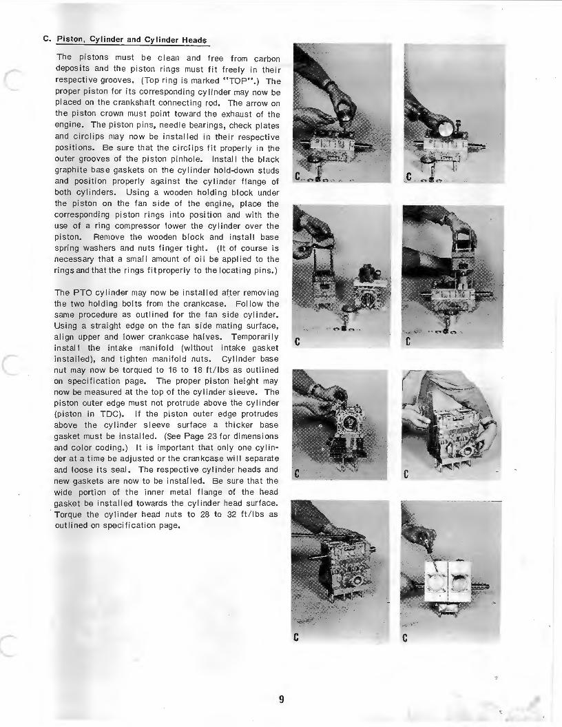
The pistons must be clean and free from carbon deposits and the piston rings must fit freely in their respective grooves. (Top ring is marked " TOP". ) The proper piston for its corresponding cylinder may now be placed on the crankshaft connecting rod. The arrow on the piston crown must point t oward the exhaust of the engine. The piston pins, needle bearings, check plates and circlips may now be installed in their respective positions. Be sure that the eire! ips fit properly in the outer grooves of the piston pinhole. Install the black graphite base gaskets on the cylinder hold-down studs and position properly against the cylinder flange of both cylinders. Using a wooden holding block under the piston on the fan side of the engine, place the corresponding piston rings into position and with the use of a ring compressor lower the cy I i nder over the piston. Remove the wooden block and install base spring washers and nuts finger tight. (It of course is necessary that a small amount of oil be applied to the rings and that the rings fit proper ly to the locating pins. )
The PTO cylinder may now be installed after removing the two holding bolts from the crankcase. Follow the same procedure as outlined for the fan side cylinder. Using a straight edge on the fan side mating surface, align upper and lower crankcas.e halves. Temporarily install the intake manifold (wi thout intake gasket installed), and tighten manifold nuts. Cylinder base nut may now be torqued to 16 to 18 ft/lbs as outlined on specification page. The proper piston height may now be measured at the top of the cylinder sleeve. The piston outer edge must not protrude above the cylinder (piston in TDC). If the piston outer edge protrudes above the cylinder sleeve surface a thi cker base gasket must be installed. (See Page 23 for dimensions and color coding.) It is important that only one cylinder at a time be adjusted or the crankcase will separate and loose its seal. The respecti ve cylinder heads and new gaskets are now to be installed. Be sure that the wide portion of the inner metal flange of the head gasket be installed towards the cylinder head surface.
· Torque the cylinder head nuts to 28 to 32 ft / lbs as outlined on specification page.
9
c c
ROCKWELL Twin Cylinder Engines Models 2F -400-6, 2F -440-3, 2F -440-5 Disassembly and Assembly Procedure
Assembly
c
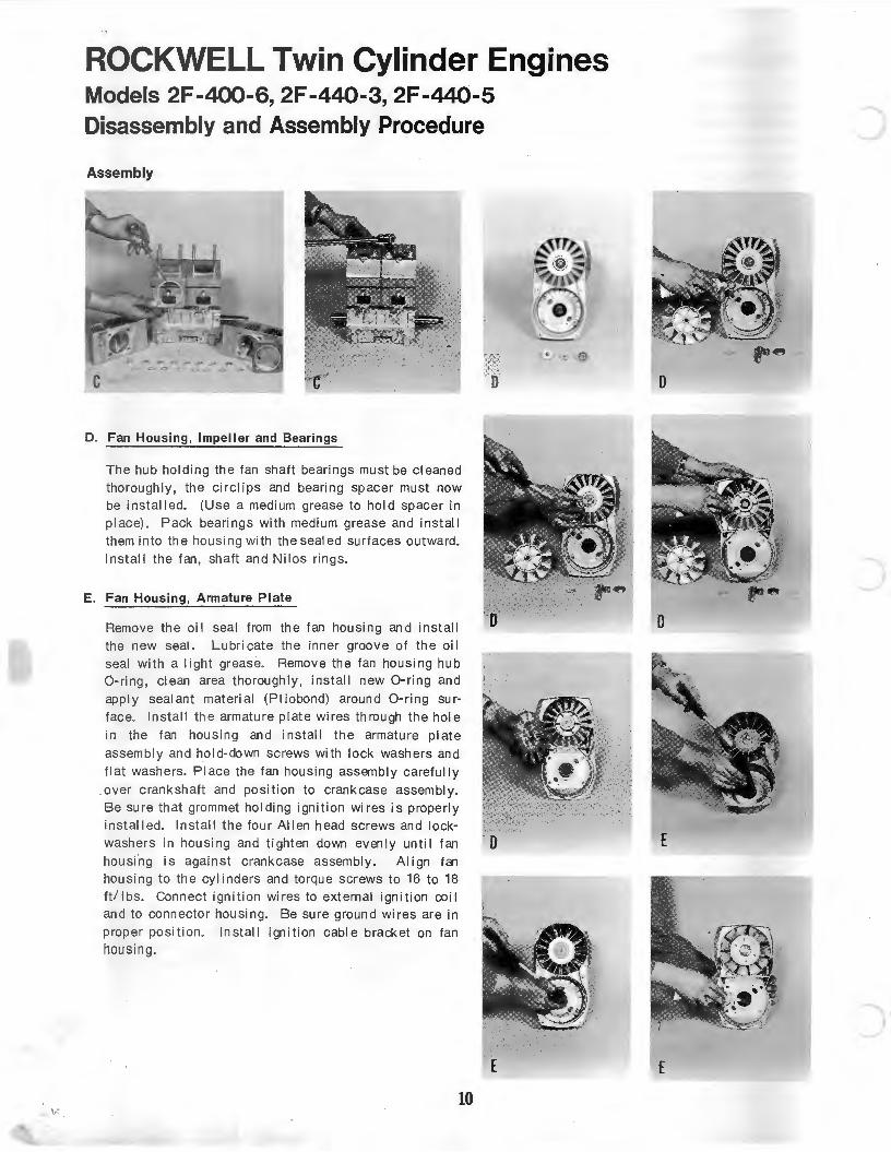
D. Fan Hou sing, Impel ler and Bearings
The hub hol ding the fan shaft bearings must be cleaned thoroughly, the circlips and bearing spacer must now be install ed. (Use a medium grease to hold spacer in place) . Pack bearings with medium grease and install them into the housing with the sealed surfaces outward. Install the fan, shaft and Nilos rings.
E. Fan Housing, Armature Plate
Remove the oil seal from the fan housing and install the new seal. Lubricate the inner groove of the oil seal with a light grease. Remove the fan housing hub 0- ring, clean area thoroughly, instal l new 0-ring and apply seal ant material (Piiobond) around 0-ring surface. Install the armature plate wires through the hole in the fan housing and install the armature plate
assembly and hold- down screws with lock wash ers and flat washers. Place the fan housing assemb ly carefully
over crankshaft and position to crankcase assembl y . Be sure that grommet holding i gnition wires is properly installed. Install the four Allen head screws and lockwashers in housing and tighten down evenl y until fan housing is against crankcase assembly. Align fan housing to the cylinders and torque screws to 16 to 18 ft/lbs. Connect ignition wires to external ignition coil and to connector housing. Be sure ground wires are in proper position. Install ignition cable bracket on fan housing.
10
D
D
D
E
)
E
E
c
c
c
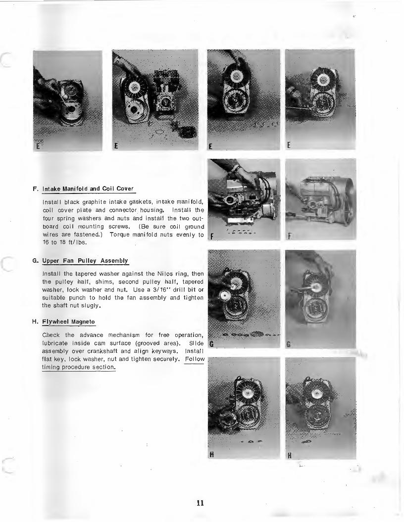
F. Intake Manifold and Coil Cover
Install black graphite intake gaskets, intake manifold, coil cover plate and connector housing. Install the
four spring washers and nuts and install the two out
bOard coi I mounting screws. (Be sure coil ground wires are fastened.) Torque manifold nuts evenly to 16 to 18 ft/ I bs.
G. Upper Fan Pulley Assembly
Install the tapered washer against the Niles ring, then the pulley half, shims, second pulley half, tapered washer, lock washer and nut. Use a 3/16" dri II bit or suitable punch to hold the fan assembly and tighten the shaft nut slugly.
H. Flywheel Magneto
Check the advance mechanism for free operation, lubricate inside c am surface (grooved area). Slide assembly over crankshaft and align keyways. Install flat key, lock washer, nut and tighten securely. Follow timing procedure section.
11
H
ROCKWELL Twin Cylinder Engines Models 2F -400-6, 2F -440-3, 2F -440-5 Disassembly and Assembly Procedure
Assembly
H
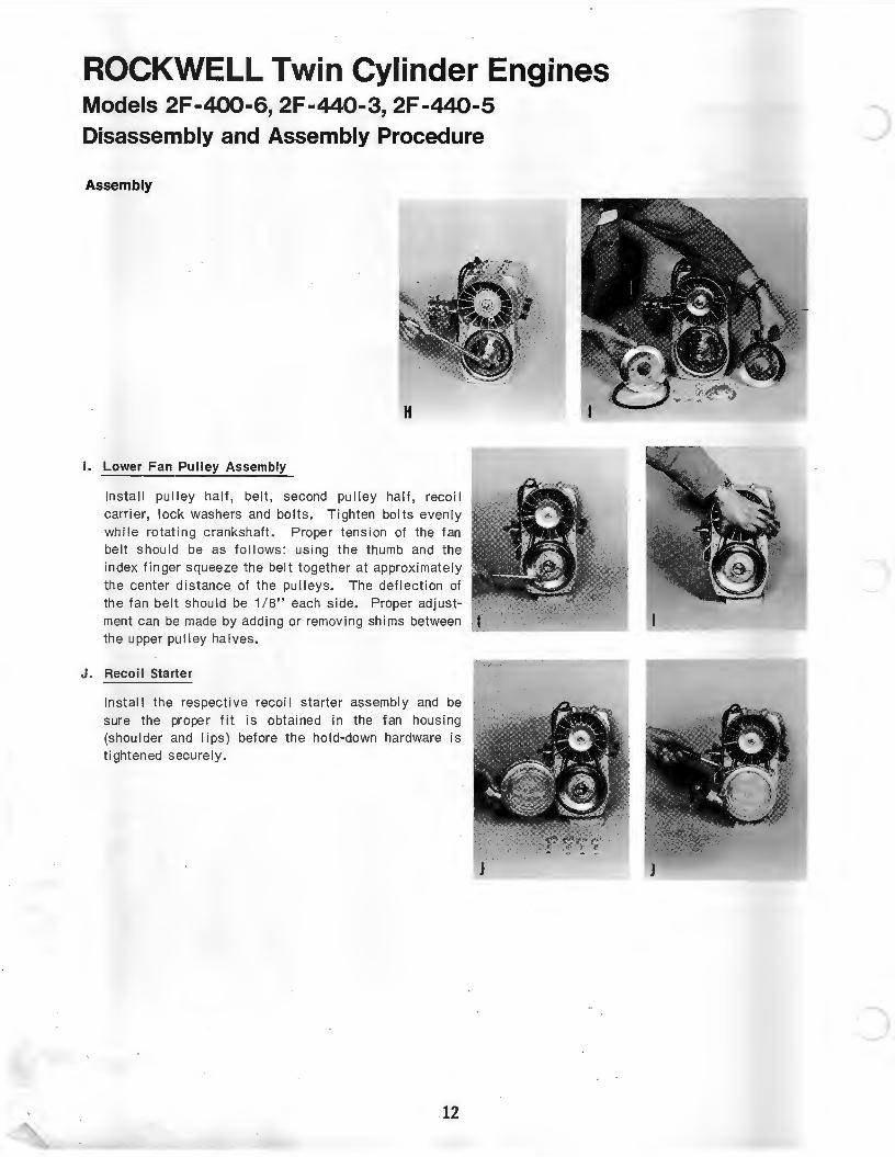
I. Lower Fan Pulley Assembly
Install pulley half, belt, second pulley half, recoil carrier, lock washers and bolts. Tighten bolts evenly while rotating crankshaft. Proper tension of the fan belt shou ld be as follows: using the thumb and the index finger squeeze the belt together at approximately the center distance of the pulleys. The deflection of the fan belt should be 1 / 8" each side. Proper adjustment can be made by adding or removing shims between the upper pulley halves.
J. Recoil Starter
Install the respective recoi I starter assembly and be sure the proper fit is obtained in the fan housing (shoulder and I ips) before the hold-down hardware is tightened securely.
12
)
c
c
ROCKWELL Twin Cylinder Engines Models 2F -400-6, 2F -440-3, 2F -440-5 Disassembly and Assembly Procedure -RECOIL sTARTER
FIRST VERSION (Aluminum)- SECOND VERSION (Steel)
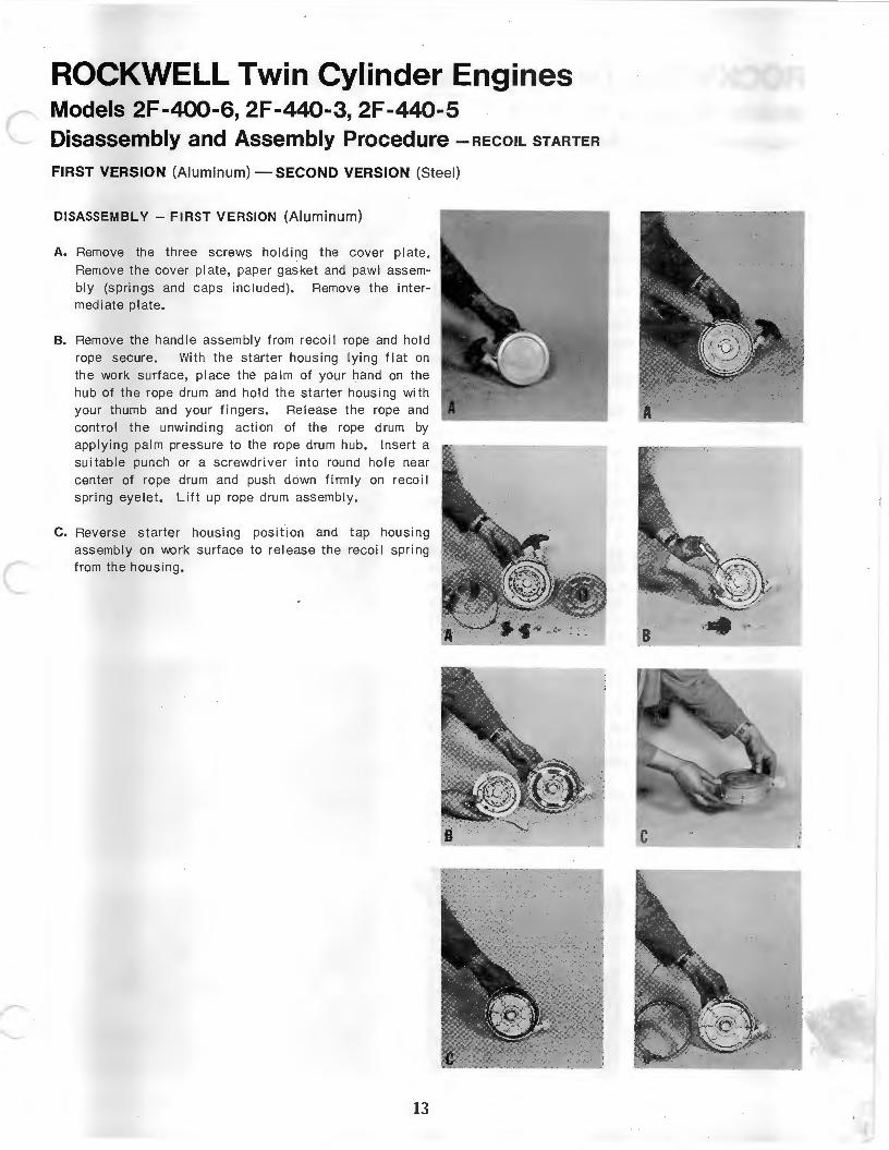
DISASSEMBLY -FIRST VERSION (Aluminum)
A. Remove the three screws holding the cover plate. Remove the cover plate, paper gasket and pawl assembly (springs and caps included). Remove the intermediate plate.
B. Remove the handle assembly from recoi I rope and hold rope secure. With the starter housing lying flat on the work surface, place the palm of your hand on the hub of the rope drum and hold the starter housing with your thumb and your fingers. Release the rope and control the unwinding action of the rope drum by applying palm pressure to the rope drum hub. Insert a suitable punch or a screwdriver into round hole near center of rope drum and push down firmly on reco i I spri ng eyelet. Lift up rope drum assembl y.
c. Reverse starter housing posit ion and tap housing assembly on work surface to release the recoil spring from the housing.
13
ROCKWELL Twin Cylinder Engines Models 2F -400-6, 2F -440-3, 2F -440-5 Disassembly and Assembly Procedure-RECOIL sTARTER
ASSEMBLY- FIRST VERSION (Aluminum)
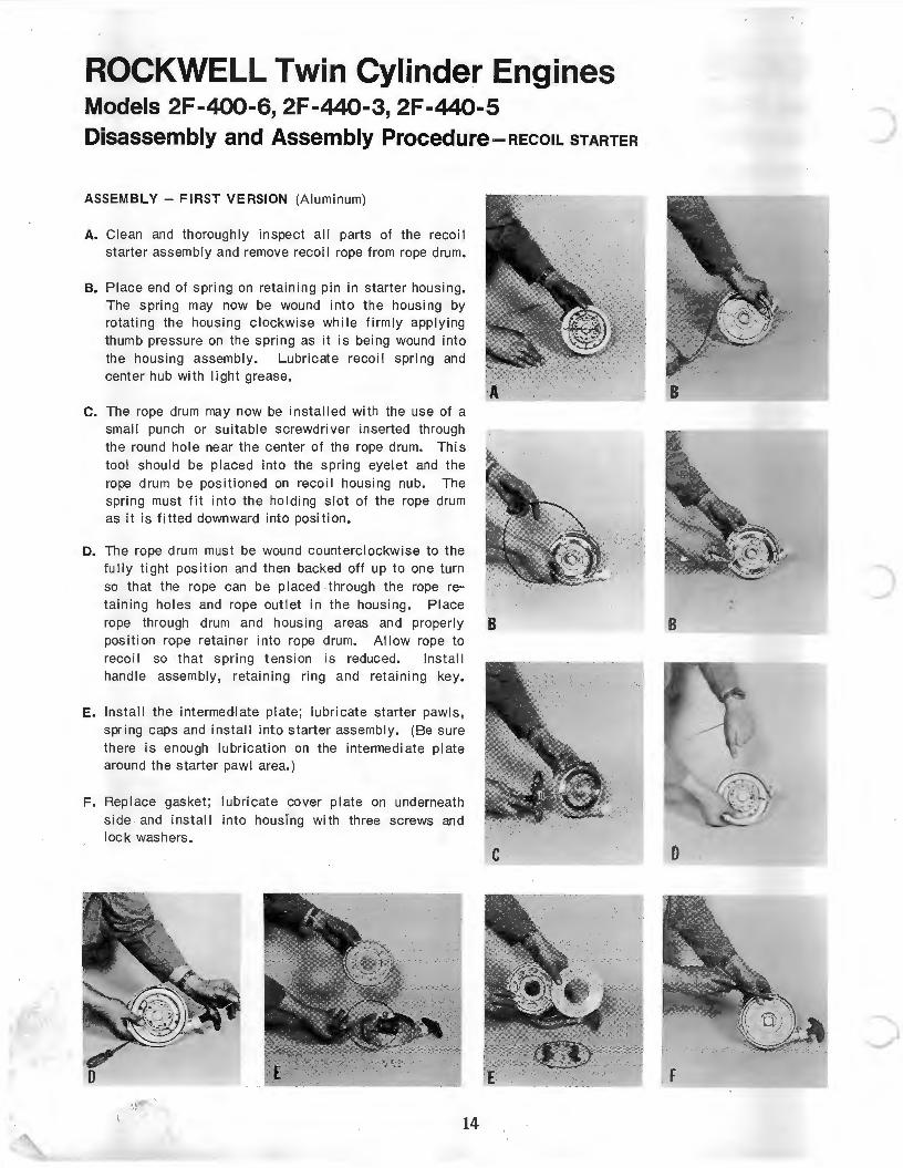
A. Clean and thoroughly inspect all parts of the recoi I starter assembly and remove recoi I rope from rope drum.
B. Place end of spring on retaining pin in starter housing. The spring may now be wound into the housing by rotating the housing clockwise while firmly applying thumb pressure on the spring as it is being wound into the housing assembly. Lubricate recoi I spring and center hub with I i ght grease.
C. The rope drum may now be installed with the use of a small punch or suitable screwdriver inserted through the round hole near the center of the rope drum. This tool should be placed into the spring eyelet and the rope drum be positioned on recoil housing nub. The spring must fit into the holding slot of the rope drum as it is fitted downward into position.
D. The rope drum must be wound counterclockwise to the fully tight position and then backed off up to one turn so that the rope can be pI aced through the rope retaining holes and rope outlet in th e housing. Place rope through drum and housing areas and properly B position rope retainer into rope drum. Al low rope to recoil so that spring t ensi on is reduced. Install handle assembly, retaining ring and retaining key.
E. Install the intermedi ate plate; lubricate starter pawls, spring caps and install into starter assembly. (Be sure there is enough lubrication on the intermediate plate around the starter pawl area.)
F. Replace gasket; lubricate cover plate on underneath side and install into housing with three screws and lock washers.
•' ,I
14
)
) B
0
' F ------------··~--~
c
c
c
ROCKWELL Twin Cylinder Engines Models 2F -400-6, 2F -440-3, 2F -440-5 Disassembly and Assembly Procedure-RECOIL STARTER
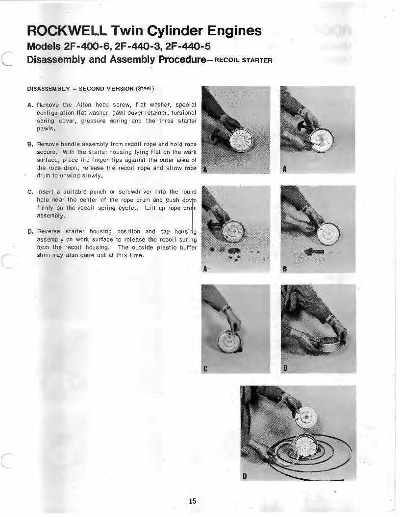
DISASSEMBLY- SECOND VERSION (Steel)
A. Remove the Allen head screw, flat washer, speci al configuration flat washer, pawl cover retainer, tors ional spring cover, pressure spring and the three starter pawls.
B. Remove handle assembly from recoil rope and hold rope secure. With the starter housing lying flat on the work surface, place the finger tips against the outer area of the rope drum, rerease the recoi I rope and allow rope drum to unwind slowly.
C. Insert a suitable punch or screwdriver into the round hole near the center of the rope drum and push down firmly on the recoi l spring eyelet. Li ft up rope drum assembly.
D. Reverse starter housing position and tap housing assembly on work surface to rerease the reco il spring from the recoil housing. The outside plastic buffer shim may also come out at this time.
15
A-
c
. ~ . ..... .. . ,. B
ROCKWELL Twin Cylinder Engines Models 2F -400-6, 2F -440-3, 2F -440-5 Disassembly and Assembly Procedure-RECOIL sTARTER
ASSEMBLY- SECOND VERSION (Steel)
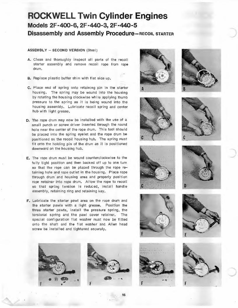
A. Clean and thorough I y inspect all parts of the recoi 1 starter assembly and remove recoi I rope from rope drum.
B. Replace plastic buffer shim with flat side up.
C. Place end of spring onto retaining pin in the starter housing. The spring may be wound into the housing by rotating the housing clockwise while applying thumb pressure to the spring as it is being wound into the housing assembly. Lubricate recoi I spring and center hub with light grease.
D. The rope drum may now be installed with the use of a small punch or screw driver inserted through the round hole near the center of the rope drum. This tool should be placed into the spring eyelet and the rope drum be positioned on the recoil housing hub. The spring must fit onto the holding pin of the drum as it is positioned downward on the housing hub.
E. The rope drum must be wound counterclockwise to the fully tight position and then backed off up to one turn so that the rope can be placed through the rope retaining hole and rope outlet in the housing. Place rope through drum · and housing area and properly position rope retainer into rope drum. Allow the rope to recoi I so that spr ing tension is reduced, install hand le assembly, retaining ring and retaining key.
F. Lubricate the starter pawl area on the rope drum and the starter pawls with a light grease. Position the three starter pawls, install the pressure spring, the torsional spring and the pawl cover retainer. The special configuration flat washer must now be fitted onto the shaft and the flat washer and Allen head screw be installed and tightened securely.
F
.. ··. 16
)
)
D
c
c
c
ROCKWELL Twin Cylinder Engines Models 2F-440-3, 2F-440-5 Ring Gear Kit Installation and Removal
INSTALLATION
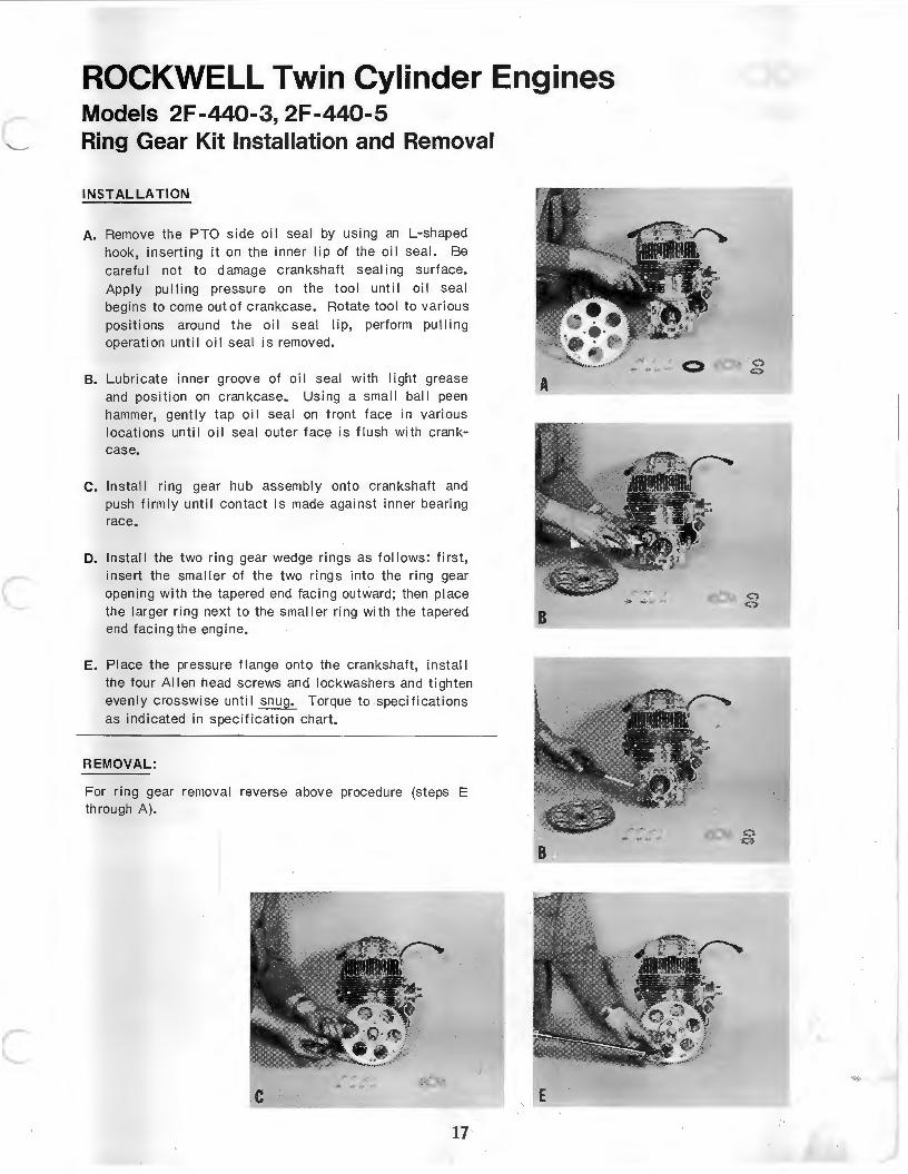
A. Remove the PTO side oil seal by using an L·shaped hook, inserting it on the inner lip of the oil seal. Be careful not to damage crankshaft sealing surface. Apply pulling pressure on the tool until oil seal begins to come out of crankcase. Rotate tool to various positions around the oil seal lip, perform pulling operation until oil seal is removed.
B. Lubricate inner groove of oil seal with light grease and position on crankcase. Using a small ball peen hammer, gently tap oil seal on front face in various locations until oil seal outer face is flush with crankcase.
C. Install ring gear hub assembly onto crankshaft and push firmly until contact is made against inner bearing race.
D. Install the two ring gear wedge rings as follows: first, insert the smaller of the two rings into the ring gear opening with the tapered end facing outward; then place the I arger ring next to the smaller ring with the tapered end facing the engine.
E. Place the pressure flange onto the crankshaft, install the four Allen head screws and lockwashers and tighten evenly crosswise until snug. Torque to specifications as indicated in specification chart.
REMOVAL:
For ring gear removal reverse above procedure (steps E through A).
c 17
E
0 0
ROCKWELL Twin Cylinder Engines Model 2F -400-6 Ring Gear Kit Installation and Removal
INSTALLATION ENGINE MODEL 2F 400M6
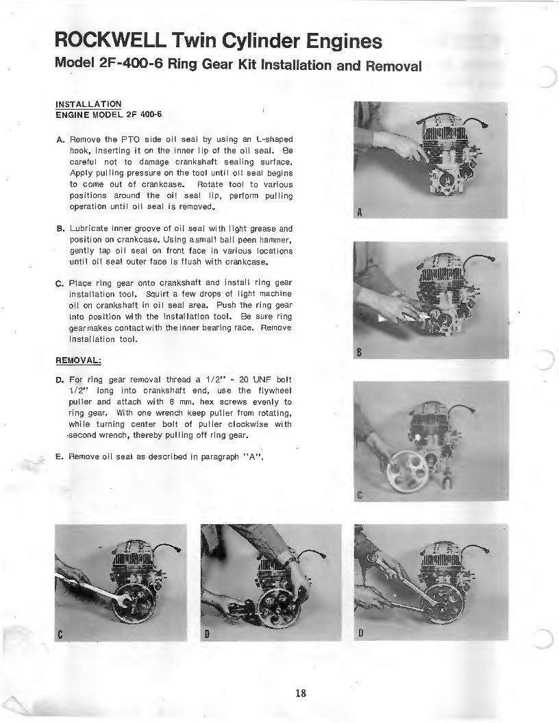
A. Remove the PTO side oil seal by using an L-shaped hook, inserting it on the inner lip of the o il seal. Be careful not to damage crankshaft sealing surface. Apply pulling pressure on the tool until oil seal begins to come out of crankcase. Rotate tool to various positions around the oi l seal lip, perform pulling operation until oil seal is removed.
B. Lubricate inner groove of oil seal with light grease and pos ition on crankcase. Using asmall ball peen hammer, gently tap oil seal on front face in various locations until oil seal outer face is flush with crankcase.
c. Place ring gear onto crankshaft and install ring gear installation tool. Squirt a few drops of li ght machine oil on crankshaft in oil seal area. Push the ring gear into positi on with the installation tool. Be sure ring gear makes contact with the inner bearing race. Remove installation tool.
REMOVAL:
D. For ring gear removal thread a 1 /2" M 20 UNF bolt 1/2" long into crankshaft end, use the flywheel puller and attach with 8 mm. hex screws evenly to ring gear. With one wrench keep puller from rotating, while turning center bolt of puller clockwise with -second wrench, thereby pulling off ring gear.
E. Remove oil seal as described in paragraph "A".
c
A
D
18
)
)
c
c
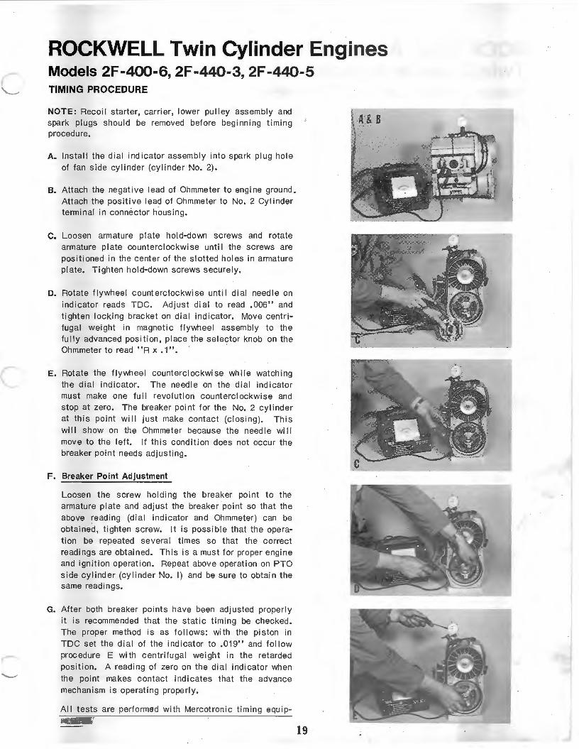
ROCKWELL Twin Cylinder Engines Models 2F -400-6, 2F -440-3, 2F -440-5 TIMING PROCEDURE
NOTE: Recoil starter, carri er, lower pulley assembly and spark plugs should be removed before beginning timing procedure.
A. Install the dial indicator assembly into spark plug hole of fan side cylinder (cy linder No. 2).
B. Attach the negative lead of Ohmmeter to engine ground. Attach the positive lead of Ohmmeter to No.2 Cylinder terminal in connector housing.
C. Loosen armature pi ate hold-down screws and rotate armature plate counterclockwise unti I the screws are positioned in the center of the slotted holes in armature plate. Tighten hold-down screws securely.
D. Rotate flywheel counterclockwise until dial needle on indicator reads TDC. Adjust dial to read .006" and tighten locking bracket on dial indicator. Move centrifugal weight in magnetic flywheel assembly to the full y advanced position, place the sele~tor knob on the Ohmmeter to read "R x .1".
E. Rotate the flywheel counterc lockwi se while watching the dial indicator. The need le on the dial indi cator must make one full revolution counterclockwise and stop at zero. The breaker point for the No. 2 cylinder at this point wi ll just make contact (closing). This wi II show on the Ohmmeter because the need I e wi II move to the left. If this condition does not occur the breaker point needs adjusting.
F. Breaker Point Adjustment
Loosen the screw holding the breaker point to the armature plate and adjust the breaker point so that the above reading (dial indicator and Ohmmeter) can be obtained, tighten screw. It is possible that the operation be repeated several times so that the correct readings are obtained. This is a must for proper engine and ignition operation . Repeat above operation on PTO side cyli nder (cylinder No. I) and be sure to obtain the same readings.
G. After both breaker points have been adjusted properly it is recommended th at the static timing be checked. The proper method is as follows: with the piston in TDC set the dial of the indicator to .019" and follow procedure E with centrifugal weight in the retarded position. A reading of zero on the dial indicator when the point makes contact indicates that the advance mechanism is operating properly.
All tests are performed with Mercotronic timing equipment.
19
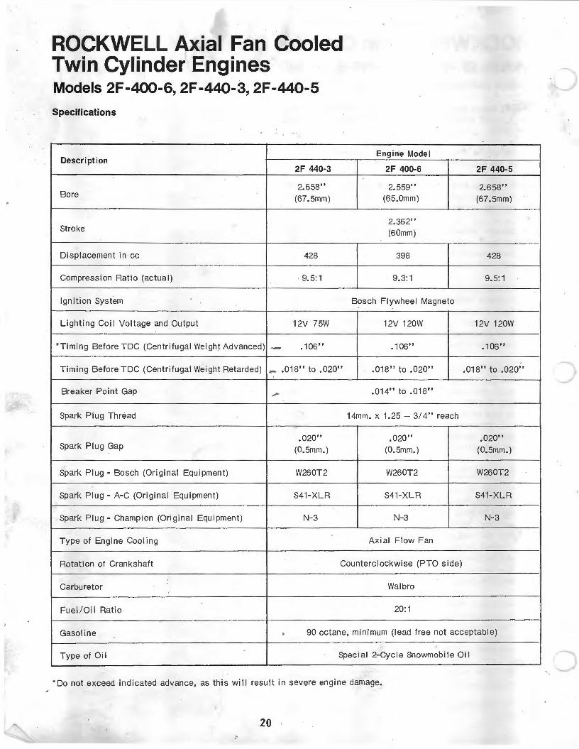
ROCKWELL Axial Fan Cooled Twin Cylinder Engines Models 2F -400-6 2F -440-3 2F -440-5 ' ' .
Specifications
Description 2F 440-3
2.658" Bore (67.5mm)
Stroke
Displacement in cc 428
Compression Ratio (actual) 9.5:1
Ignition System
Lighting Coi I Voltage and Output 12V 75W
*Timing BeforeTDC (Centrifugal Weight Advanced) ·- .106"
Timing Before TDC (Centrifugal Weight Retarded) _ .018" to .020"
Breaker Point Gap _,
Spark Plug Thread
• 020" Spark Plug Gap (0.5mm.)
Spark Plug- Bosch (Original Equipment) W260T2
Spark Plug- A-C (Original Equipment) S41-XLR
Spark Plug- Champion (Original Equipment) N-3
Type of Engine Cooling
Engine Model
2F 400-6
2.559" (65.0mm)
2.362" (60mm)
398
9.3:1
Bosch Flywheel Magneto
12V 120W
• 1 06"
.018" to .020"
.014" to .018"
14mm. x 1.25 - 3/ 4" reach
.020" (0.5mm. )
W260T2
S41-XLR
N-3
Axial Flow Fan
Rotation of Crankshaft Counterclockwise (PTO side)
Carburetor Walbro
Fuel / Oil Ratio 20:1
2F 440-5
2.658" (67.5mm)
428
9.5:1
12V 120W
.106"
.018" to .020"
.020" (0.5mm.)
W260T2
S41-XLR
N-3
Gasoline • 90 octane, minimum (lead free not acceptable)
Type of Oil Special 2-Cycle Snowmobile Oil
*Do not exceed indicated advance, as this will result in severe engine damage.
20 ·'
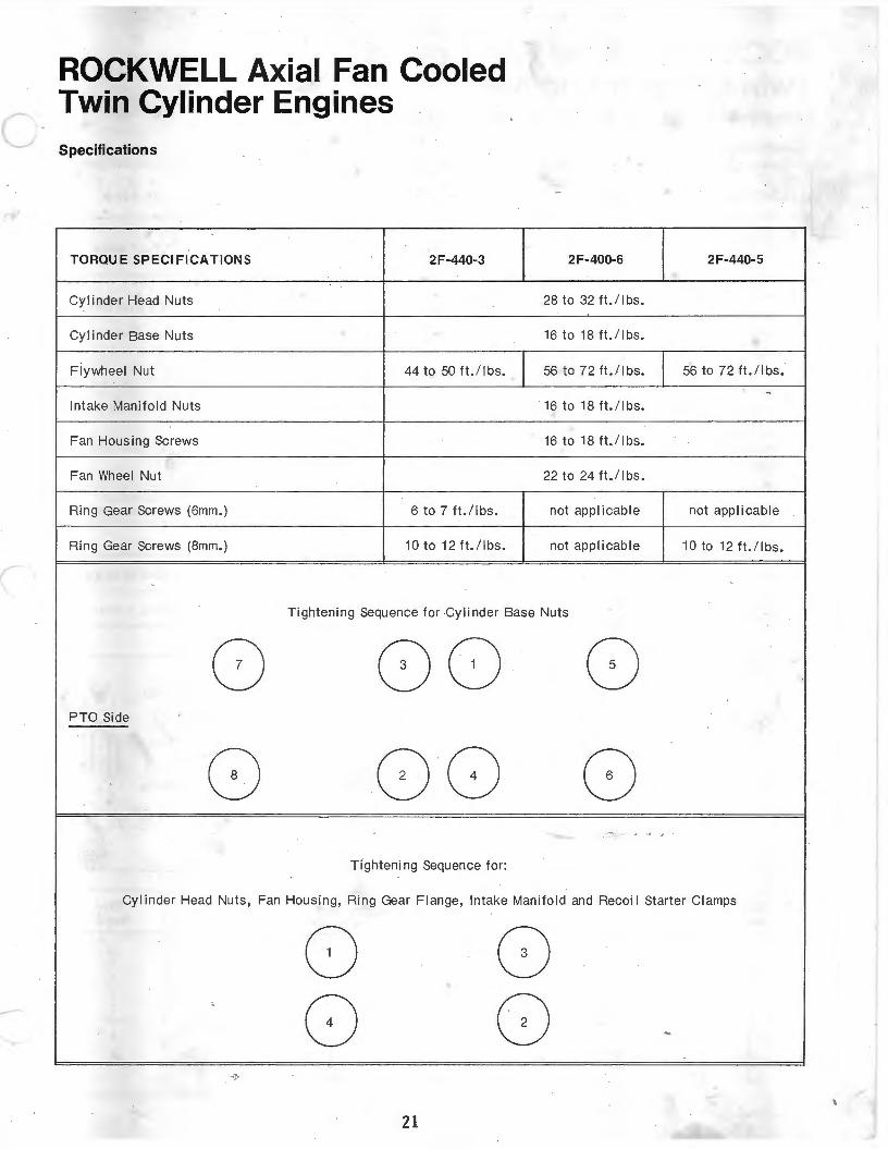
c ROCKWELL Axial Fan Cooled Twin Cylinder Engines Specifications
TORQU E SP ECIFICATIONS 2F-440-3
Cylinder Head Nuts
Cylinder Base Nuts
Flywheel Nut 44 to 50 ft./lbs.
Int ake Manifold Nuts
Fan Housing Screws
Fan Wheel Nut
Ring Gear Screws (6mm.) 6 to 7 ft. / lbs.
Ring Gear Screws (8mm.) 10 to 12 ft./lbs.
2F-400-6
28 to 32 ft. / lbs.
16 to 18 ft. / lbs.
56 to 72 ft.! I bs.
· 16 to 18 ft. / lbs.
16 to 18 ft./ lbs.
22 to 24 ft./lbs.
not applicable
not applicable
Tightening Sequence for Cylinder Base Nuts
0 0 0 0 PTO Side
8 0 () 8 - . '
T ightening Sequence for:
2F-440- 5
56 to 72 ft./ I bs.
..
not app l icable
10 to 12 ft. / lbs.
' '
Cylinder Head Nuts, Fan Housing, Ring Gear Flange, Intake Manifold and Recoi I Starter Clamps
0 8 '
' 0 8 -··J·
21

Scorpion Inc. Crosby,Minnesota 56441
SV~l-7735-1 5/72 (3 . 5M) Printed in U.S.A.