Embed Size (px)
Citation preview
SERVICEMANUAL
iPF6100
COPYRIGHT 2006 CANON INC. CANON imagePROGRAF iPF6100 REV. 0 PRINTED IN U.S.A.
JULY 2007REV. 0
DU7-1226-000
fineline6
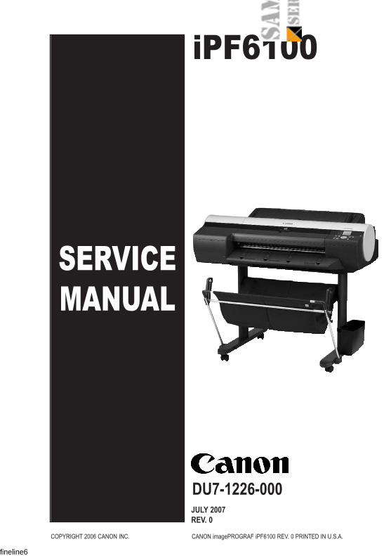
Contents
Contents
Chapter 1 PRODUCT DESCRIPTION
1.1 Product Overview .............................................................................................. 1-11.1.1 Product Overview....................................................................................................... 1-1
1.2 Features.............................................................................................................. 1-31.2.1 Features....................................................................................................................... 1-31.2.2 Printhead ..................................................................................................................... 1-31.2.3 Ink Tank ....................................................................................................................... 1-41.2.4 Cutter ........................................................................................................................... 1-41.2.5 Roll Feed Unit ............................................................................................................. 1-41.2.6 Stand ............................................................................................................................ 1-61.2.7 IEEE1394 (FireWire) Board...................................................................................... 1-71.2.8 Consumables .............................................................................................................. 1-7
.3 Product Specifications ...................................................................................... 1-81.3.1 Product Specifications............................................................................................... 1-8
.4 Detailed Specifications ................................................................................... 1-121.4.1 Print Speed and Direction....................................................................................... 1-121.4.2 Interface Specifications ........................................................................................... 1-19
.5 Names and Functions of Components ........................................................ 1-201.5.1 Front ........................................................................................................................... 1-201.5.2 Rear............................................................................................................................ 1-211.5.3 Top Cover (Inside) ................................................................................................... 1-221.5.4 Manual Loading Area .............................................................................................. 1-231.5.5 Roll Feed Unit Cover (Inside)................................................................................. 1-241.5.6 Carriage ..................................................................................................................... 1-251.5.7 Inside.......................................................................................................................... 1-26
1.6 Basic Operation ............................................................................................... 1-271.6.1 Operation Panel ....................................................................................................... 1-271.6.2 Main Menu................................................................................................................. 1-28
1.7 Safety and Precautions .................................................................................. 1-511.7.1 Safety Precautions ...................................................................................................1-51
1.7.1.1 Moving Parts ....................................................................................................................... 1-511.7.1.2 Adhesion of Ink ................................................................................................................... 1-521.7.1.3 Electric Parts ....................................................................................................................... 1-54
1.7.2 Other Precautions ....................................................................................................1-541.7.2.1 Printhead.............................................................................................................................. 1-541.7.2.2 Ink Tank ............................................................................................................................... 1-57
fineline6
Contents
1.7.2.3 Handling the Printer ........................................................................................................... 1-581.7.3 Precautions When Servicing Printer .................................................................... 1-62
1.7.3.1 Notes on the Data Stored in the Printer ......................................................................... 1-621.7.3.2 Confirming the Firmware Version .................................................................................... 1-621.7.3.3 Precautions against Static Electricity .............................................................................. 1-621.7.3.4 Precautions for Disassembly/Reassembly..................................................................... 1-621.7.3.5 Self-diagnostic Feature ..................................................................................................... 1-631.7.3.6 Disposing of the Lithium Battery ...................................................................................... 1-63
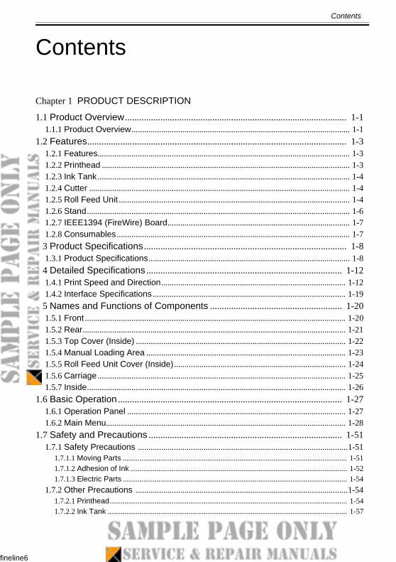
Chapter 2 TECHNICAL REFERENCE
2.1 Basic Operation Outline .................................................................................... 2-12.1.1 Printer Diagram ......................................................................................................... 2-12.1.2 Print Signal Sequence .............................................................................................. 2-22.1.3 Print Driving................................................................................................................ 2-3
2.2 Firmware ............................................................................................................. 2-62.2.1 Operation Sequence at Power-on .......................................................................... 2-62.2.2 Operation Sequence at Power-off .......................................................................... 2-72.2.3 Print Control ............................................................................................................... 2-72.2.4 Print Position Adjustment Function ...................................................................... 2-152.2.5 Head Management ................................................................................................. 2-152.2.6 Printhead Overheating Protection Control .......................................................... 2-162.2.7 Pause between Pages ........................................................................................... 2-162.2.8 White Raster Skip ................................................................................................... 2-162.2.9 Sleep Mode .............................................................................................................. 2-16
2.3 Printer Mechanical System............................................................................. 2-172.3.1 Outline ....................................................................................................................... 2-17
2.3.1.1 Outline.................................................................................................................................. 2-172.3.2 Ink Passage ............................................................................................................. 2-18
2.3.2.1 Ink Passage ........................................................................................................................ 2-182.3.2.2 Ink Tank Unit ....................................................................................................................... 2-202.3.2.3 Carriage Unit ....................................................................................................................... 2-232.3.2.4 Printhead ............................................................................................................................. 2-292.3.2.5 Purge Unit ........................................................................................................................... 2-302.3.2.6 Maintenance Cartridge ...................................................................................................... 2-382.3.2.7 Air Flow ................................................................................................................................ 2-39
2.3.3 Paper Path ............................................................................................................... 2-402.3.3.1 Outline.................................................................................................................................. 2-402.3.3.2 Paper Path .......................................................................................................................... 2-412.3.3.3 Cutter Unit ........................................................................................................................... 2-53
2.4 Printer Electrical System................................................................................. 2-542.4.1 Outline ....................................................................................................................... 2-54
2.4.1.1 Overview.............................................................................................................................. 2-542.4.2 Main Controller ........................................................................................................ 2-56
fineline6
Contents
2.4.2.1 Main controller components.............................................................................................. 2-562.4.3 Carriage Relay PCB ................................................................................................2-58
2.4.3.1 Carriage PCB components ............................................................................................... 2-582.4.4 Motor Driver ..............................................................................................................2-59
2.4.4.1 Roll feed unit PCB components ....................................................................................... 2-592.4.5 Maintenance Cartridge Relay PCB .......................................................................2-59
2.4.5.1 Maintenance cartridge relay PCB components ............................................................. 2-592.4.6 Power Supply ............................................................................................................2-60
2.4.6.1 Power supply block diagram............................................................................................. 2-60.5 Detection Functions with Sensors ................................................................ 2-61
2.5.1 Sensors for covers ................................................................................................... 2-612.5.2 Ink passage system ................................................................................................. 2-622.5.3 Carriage system ....................................................................................................... 2-662.5.4 Paper path system ................................................................................................... 2-682.5.5 Others ........................................................................................................................ 2-71
Chapter 3 INSTALLATION
3.1 Installation .......................................................................................................... 3-13.1.1 Making Pre-Checks ...................................................................................................3-1
3.1.1.1 Making Pre-Checks .............................................................................................................. 3-13.1.2 Unpacking and Installation .......................................................................................3-1
3.1.2.1 Unpacking and Installation .................................................................................................. 3-13.1.2.2 Installing the Stand............................................................................................................. 3-10
3.1.3 Checking the Images/Operations ..........................................................................3-183.1.3.1 Checking the Images /Operations ................................................................................... 3-18
3.2 Transporting the Printer ................................................................................. 3-183.2.1 Transporting the Printer ..........................................................................................3-18
3.2.1.1 Transporting the Printer..................................................................................................... 3-183.2.2 Reinstalling the Printer ............................................................................................3-19
3.2.2.1 Reinstalling the Printer ...................................................................................................... 3-19
Chapter 4 DISASSEMBLY/REASSEMBLY
4.1 Service Parts...................................................................................................... 4-14.1.1 Service Parts............................................................................................................... 4-1
4.2 Disassembly/Reassembly................................................................................ 4-14.2.1 Disassembly/Reassembly......................................................................................... 4-1
4.3 Points to Note on Disassembly and Reassembly ........................................ 4-14.3.1 Note on assemblies (or units) prohibited from disassembly ............................... 4-14.3.2 Moving the carriage manually .................................................................................. 4-24.3.3 Units requiring draining of ink................................................................................... 4-2
fine
Contents
4.3.4 External Covers ......................................................................................................... 4-34.3.5 Driving Unit ............................................................................................................... 4-194.3.6 Cutter......................................................................................................................... 4-204.3.7 Carriage Unit ............................................................................................................ 4-234.3.8 Feeder Unit............................................................................................................... 4-344.3.9 Roll Feed Unit .......................................................................................................... 4-384.3.10 Purge Unit............................................................................................................... 4-424.3.11 Waste Ink Collection Unit ..................................................................................... 4-454.3.12 Ink Tank Unit .......................................................................................................... 4-504.3.13 Head Management Sensor.................................................................................. 4-544.3.14 Multi Sensor ........................................................................................................... 4-554.3.15 PCBs ....................................................................................................................... 4-564.3.16 Opening the Cap/Moving the Wiper Unit........................................................... 4-604.3.17 Opening/Closing the Ink Supply Valve .............................................................. 4-614.3.18 Draining the Ink ..................................................................................................... 4-62
4.4 Applying the Grease ........................................................................................ 4-644.4.1 Applying the Grease ............................................................................................... 4-64
4.5 Adjustment and Setup Items .......................................................................... 4-694.5.1 Adjustment Item List ............................................................................................... 4-694.5.2 Procedure after Replacing the Carriage Unit or Multi Sensor.......................... 4-694.5.3 Procedure after Replacing the Head Management Sensor ............................. 4-73
Chapter 5 MAINTENANCE
5.1 Periodic Replacement Parts............................................................................. 5-15.1.1 Periodic Replacement Parts .................................................................................... 5-1
5.2 Consumable Parts ............................................................................................. 5-15.2.1 Consumable Parts..................................................................................................... 5-1
5.3 Periodic Maintenance........................................................................................ 5-25.3.1 Periodic Maintenance ............................................................................................... 5-2
Chapter 6 TROUBLESHOOTING
6.1 Troubleshooting ................................................................................................. 6-16.1.1 Outline ......................................................................................................................... 6-1
6.1.1.1 Outline of Troubleshooting ................................................................................................. 6-16.2 Location of Connectors and Pin Arrangement .............................................. 6-2
6.2.1 Main controller PCB .................................................................................................. 6-26.2.2 Carriage PCB ........................................................................................................... 6-206.2.3 Power supply ........................................................................................................... 6-336.2.4 Roll feed unit PCB ................................................................................................... 6-34
6.3 Version Up ........................................................................................................ 6-36
finel
Conten
6.3.1 Firmware Update Tool............................................................................................. 6-6.4 Service Tools ................................................................................................... 6-3
6.4.1 Tool List ..................................................................................................................... 6-
Chapter 7 SERVICE MODE
7.1 Service Mode ..................................................................................................... 77.1.1 Service Mode Operation ........................................................................................... 77.1.2 Map of the Service Mode .......................................................................................... 77.1.3 Details of Service Mode .......................................................................................... 7-7.1.4 Sample Printout ........................................................................................................ 7-
7.2 Special Mode ................................................................................................... 7-37.2.1 Special Modes for Servicing................................................................................... 7-34
Chapter 8 ERROR CODE
8.1 Outline................................................................................................................. 8-18.1.1 Outline.......................................................................................................................... 8-1
8.2 Warning Table ................................................................................................... 8-28.2.1 Warnings ..................................................................................................................... 8-2
8.3 Error Table ......................................................................................................... 8-48.3.1 Error Code List ........................................................................................................... 8-4
.4 Sevice Call Table ............................................................................................ 8-248.4.1 Service Call Errors ................................................................................................... 8-24
fineline6
Chapter 4
DISASSEMBLY/REASSEMBLY
fineline6
Contents
Contents
4.1 Service Parts...................................................................................................... 4-14.1.1 Service Parts............................................................................................................... 4-1
4.2 Disassembly/Reassembly................................................................................ 4-14.2.1 Disassembly/Reassembly......................................................................................... 4-1
4.3 Points to Note on Disassembly and Reassembly ........................................ 4-14.3.1 Note on assemblies (or units) prohibited from disassembly ............................... 4-14.3.2 Moving the carriage manually .................................................................................. 4-24.3.3 Units requiring draining of ink................................................................................... 4-24.3.4 External Covers .......................................................................................................... 4-34.3.5 Driving Unit................................................................................................................ 4-194.3.6 Cutter ......................................................................................................................... 4-204.3.7 Carriage Unit............................................................................................................. 4-234.3.8 Feeder Unit ............................................................................................................... 4-344.3.9 Roll Feed Unit ........................................................................................................... 4-384.3.10 Purge Unit ............................................................................................................... 4-424.3.11 Waste Ink Collection Unit...................................................................................... 4-454.3.12 Ink Tank Unit........................................................................................................... 4-504.3.13 Head Management Sensor................................................................................... 4-544.3.14 Multi Sensor ............................................................................................................ 4-554.3.15 PCBs ........................................................................................................................ 4-564.3.16 Opening the Cap/Moving the Wiper Unit............................................................ 4-604.3.17 Opening/Closing the Ink Supply Valve ............................................................... 4-614.3.18 Draining the Ink ...................................................................................................... 4-62
.4 Applying the Grease ....................................................................................... 4-644.4.1 Applying the Grease ................................................................................................ 4-64
.5 Adjustment and Setup Items ......................................................................... 4-694.5.1 Adjustment Item List ................................................................................................ 4-694.5.2 Procedure after Replacing the Carriage Unit or Multi Sensor .......................... 4-694.5.3 Procedure after Replacing the Head Management Sensor .............................. 4-73
fineline6
Chapter 4
4-1
4.1 Service Parts
4.1.1 Service Parts
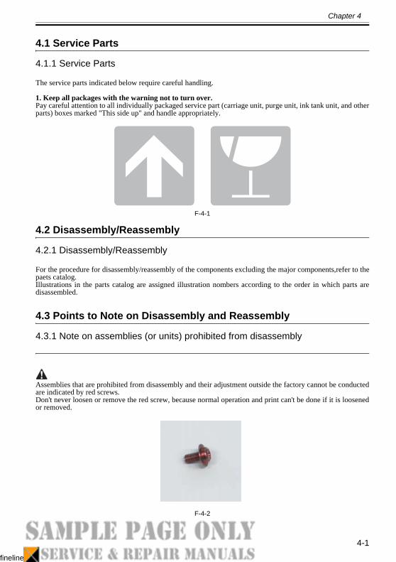
The service parts indicated below require careful handling.
1. Keep all packages with the warning not to turn over. Pay careful attention to all individually packaged service part (carriage unit, purge unit, ink tank unit, and otherparts) boxes marked "This side up" and handle appropriately.
F-4-1
4.2 Disassembly/Reassembly
4.2.1 Disassembly/Reassembly
For the procedure for disassembly/reassembly of the components excluding the major components,refer to thepaets catalog.Illustrations in the parts catalog are assigned illustration nombers according to the order in which parts aredisassembled.
4.3 Points to Note on Disassembly and Reassembly
4.3.1 Note on assemblies (or units) prohibited from disassembly
Assemblies that are prohibited from disassembly and their adjustment outside the factory cannot be conductedare indicated by red screws.Don't never loosen or remove the red screw, because normal operation and print can't be done if it is loosenedor removed.
F-4-2
fineline
hapter 4
4-2
4.3.2 Moving the carriage manually
Move the carriage as required during disassembly/reassembly to prevent the carriage form contacting the parto be removed.The carriage does not move when capped. When uncapping moving the carriage, refer to the procedures DISASSEMBLY/REASSEMBLY>Points to Note on Disassembly and Reassembly>Opening the Cap/Movinthe Wiper Unit.
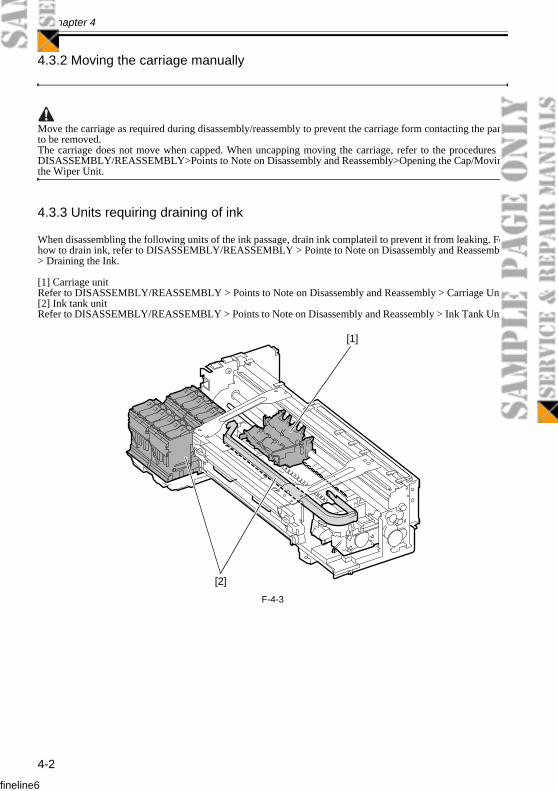
4.3.3 Units requiring draining of ink
When disassembling the following units of the ink passage, drain ink complateil to prevent it from leaking. Fohow to drain ink, refer to DISASSEMBLY/REASSEMBLY > Pointe to Note on Disassembly and Reassemb> Draining the Ink.
[1] Carriage unitRefer to DISASSEMBLY/REASSEMBLY > Points to Note on Disassembly and Reassembly > Carriage Uni[2] Ink tank unitRefer to DISASSEMBLY/REASSEMBLY > Points to Note on Disassembly and Reassembly > Ink Tank Uni
F-4-3
[1]
[2]
fineline6

Chapter 6
TROUBLESHOOTING
fineline6
Contents
Contents
6.1 Troubleshooting................................................................................................. 6-16.1.1 Outline ..........................................................................................................................6-1
6.1.1.1 Outline of Troubleshooting .................................................................................................. 6-16.2 Location of Connectors and Pin Arrangement ............................................. 6-2
6.2.1 Main controller PCB................................................................................................... 6-26.2.2 Carriage PCB............................................................................................................ 6-206.2.3 Power supply ............................................................................................................ 6-336.2.4 Roll feed unit PCB.................................................................................................... 6-34
6.3 Version Up........................................................................................................ 6-366.3.1 Firmware Update Tool............................................................................................. 6-36
6.4 Service Tools ................................................................................................... 6-376.4.1 Tool List ..................................................................................................................... 6-37
fineline6
Chapter
6-1
.1 Troubleshooting
.1.1 Outline
.1.1.1 Outline of Troubleshooting
Outlineroubles subject to troubleshooting are classified into those shown on the display (warning, error, and serall) and those not shown on the display. Precautions for Troubleshooting
1) Check the environmental conditions and the media used for printing.2) Before performing troubleshooting, make sure that all connectors and cables are connected properly3) When servicing the printer with the external cover removed and the AC power supplied, be extremcareful to avoid electric shock and shorting electrical devices.4) In the following sections, the troubleshooting steps are described such that the component related to most probable cause of the problem will be repaired or replaced first, being followed by components less problem probability. If multiple components have the same problem probability, the steps are descrbegging with the easiest one.After performing each step, check to see if the problem has been resolved by making test prints. If theproblem persists, proceed to the next step.5) After completion of the troubleshooting, check that all connectors and cables have been reconnected andscrews have been tightened firmly.6) Whenever you have performed replacement or repair services, make test prints to check whether theproblem has been resolved.
fineline6
Chapter 6
6-2
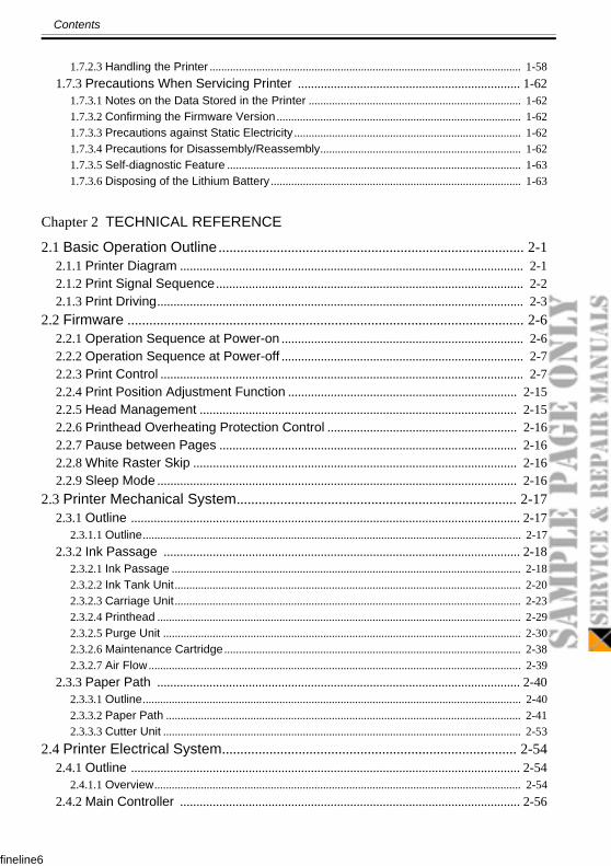
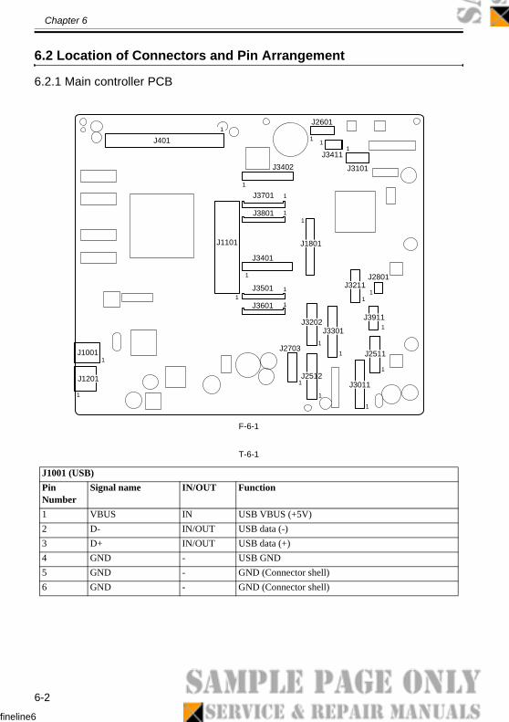
6.2 Location of Connectors and Pin Arrangement
6.2.1 Main controller PCB
F-6-1
T-6-1
J1001 (USB)Pin Number
Signal name IN/OUT Function
1 VBUS IN USB VBUS (+5V)2 D- IN/OUT USB data (-)3 D+ IN/OUT USB data (+)4 GND - USB GND5 GND - GND (Connector shell)6 GND - GND (Connector shell)
1
3 033 0
3 1
3 1
2 1
3 12 2
1
1J401
J2601
J3411
J3101J3402
J1101
J3701
J3801
1 0J1801
J3401
J3501
J3601
J1201
J1001 J2703
J3202J3301
J3211J2801
J3911
J2511
J3011J2512
1
1
1
1
1
1
1
1
1
1
11
1
1
1
1
1 1
1
1
11
1
fineline6

iPF6100
6100 REV. 0 PRINTED IN U.S.A.
00
PARTSCATALOG
COPYRIGHT ©2006 CANON INC. CANON imagePROGRAF iPF
JULY 2007REV. 0
DU7-3199-0
fineline6

fineline6
PREFACE
This Parts Catalog contains listings of parts used
Diagrams are provided with the listings to aid the service technician in identifying clearly, the
item to be orderd.
Whenever ordering parts, consult this Parts Catalog for all of the information pertaining to each
item. Be sure to include, in the Parts Request, the full item description, the item part number,
and the quantity.
COPYRIGHT (C) 1999 CANON INC.
Use of this manual should be
strictly supervised to avoid
disclosure of confidential
information.
Contents
fineline6
NUMERICAL INDEX
iPF6100(Numerical Index) ................................................................. 1-1
iPF6100(Parts Catalog)
01 PRINTER & ACCESSORIES .................................................2-102 ROLL UNIT ............................................................................2-303 COVERS (1) ..........................................................................2-604 COVERS (2) ..........................................................................2-805 ELECTRICAL PART ............................................................2-1006 PURGE UNIT .......................................................................2-1207 CUTTER UNIT .....................................................................2-1408 INK SUPPLY UNIT ..............................................................2-1609 LINEAR SCALE & LIFT DRIVE UNIT ..................................2-1810 CARRIAGE UNIT .................................................................2-2011 CARRIAGE & FEED MOTOR UNIT ....................................2-2212 PINCH ROLLER UNIT .........................................................2-2413 AIR FLOW FAN UNIT ..........................................................2-2614 PLATEN & SPUR UNIT .......................................................2-2815 TOOL ...................................................................................2-30R1 STAND UNIT .......................................................................2-31