Embed Size (px)
Citation preview
Service Manual Repairs and maintenance
Section 1 (17)
7,500 Mile Maintenance Service 1984 DL, GL GLE (Canada)
Diesel
Contents
Introduction ............ .. .. .. .. . .................. . ..... .
Volvo 7.500 Mile Maintenance Service Chart ......... • ......
7,500 Mile Maintenance Service Procedures Contrals and lighting .................................. ... . In ear .................................................... . Exterior . . . . . . . . . . . . . . . . . . . . ............... . . . • . . •. . . ...
On lift - Tires, wheels ..... ...... . ... . ... . ......... . . ...... . ... . - Front end ...............•...... . .. . ...... . . . . ... ..... . - Brakes ............ .... . . ... . .. . ......... .... . - Power transmission. . . . . .. ........•.. . ...... . ..•.. - Rear end....... . ... . ...... . ............. ............. . - Exhaust system, Diesel. . . . . . . . . . . . . . . .. . ... . . . .. . . ... . . - Rear axle, manual transmission ... ... . . .......... • ........ - Engine oil and filter:
*Gasoline engines ....................... . .... .• . ..... . . * Diesel engine ............ ... . . . .. .. .
Under hood: - Engine cooling system .................... .... ... ... . . .. . - Fluids. ................... . . .............. . - Replacing automatic transmission fluid . .... . . ...... . . .... .
B21 and B23 - M iseelIaneous ......... . ........................•........ - Adjust valves . .................. ... .... . ..... . . . .... .... . - Replace timing gear belt ...... ...... .. . . ...... . ......... .
B21A/Canada : - MiseelIaneous ................ . . . .... . . . .• . . . • ... .. . .. . . . - ca emissions check ................. . . . . . .. ...... .
B21F-Turbo: ............. . . . . ...... .. ... .. ....... •..... ...
B23F: .. ..... .. . .......... . . . . ...• . .• ... . . .• ... • .. • .....•..
024 diesel: - MiseelIaneous .. . . . . . . ........................ . . .. . - Valve clearance adjustment . ......... . .. . . . .. . . . ........ . - Idle speeds . . . . . . . . . . . . . . . . . ....... .............. • . - Setting engine controls ...... ... . . .• .. . ........... . . .. - Compression test . ................. ... . . . .. . .. ... ...... . . - Checking/adjusting injectors ... . . . . .•...... • . - Replacing timing gear belts .. ...... ..... ... . .. . .. .. ... .
Road test ............ . ..... . .. • ........ . ........
TP 30600/1 7500.08.83
Printed in U.S.A.
Operation Page 1
2
1-18 10 A1-A6 15 81 - 83 17
C1 -C4 18 01 - 010 19 E1 - E4 22 Fl - F4 23 G1 - G2 24 H1 25 11-12 25 • J1-J2 26 J3-J4 27
K1-K2 28 • K3-K5 28 L1 -L10 29
M1 -M3 33 N1-N15 34 01-07 37
P1 - P15 39 01 -016 44
R1 - R16 49 • S1-S7 55
al - a7 58 b1 - b12 60 el - c6 63 d1 - d7 64 el - el0 67 f1- f8 70 91- 933 73
82
•
Group 77, 7,500 Mile Maintenance Service - Chart
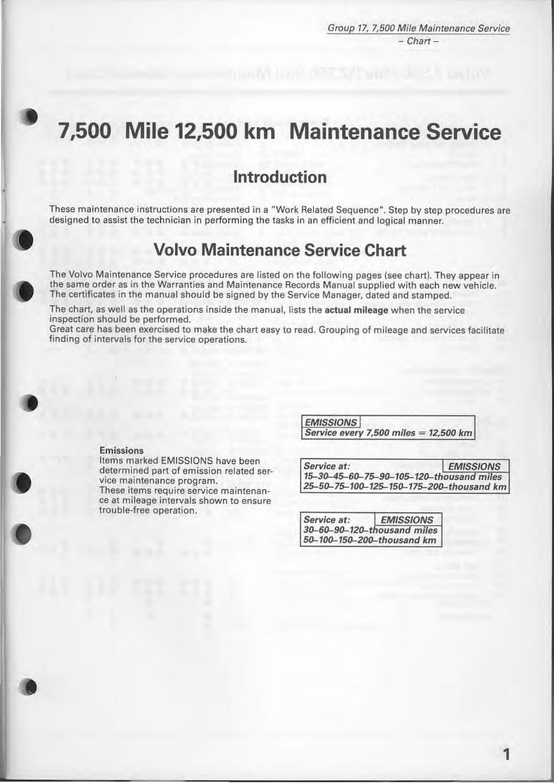
7,500 Mile 12,500 km Maintenance Service
Introduction
These maintenance instructions are presented in a "Work Related Sequence". Step by step procedures are designed to assist the technician in performing the tasks in an efficient and logical manner.
Volvo Maintenance Service Ch art The Volvo Maintenance Service procedures are listed on the following pages (see ch art). They appear in the same order as in the Warranties and Maintenance Records Manual supplied with each new vehicle. The certificates in the manual should be signed by the Service Manager, dated and stamped.
The chart, as weil as the operations inside the manual , lists the actual mileage when the service inspection should be performed. Great care has been exercised to make the chart easy to read. Grouping of mileage and services facilitate finding of intervals for the service operations.
Emissions Items marked EMISSIONS have been determined part of emission related service maintenance program. These items require service maintenance at mileage intervals shown to ensure trouble-free operation.
EMISSIONS Service every 7,500 miles = 12,500 km
Service at: L EMISSIONS 15-30-45-60-75-90-105-120-thousand miles 25-50-75-100-125-150-175-200-thousand km
Service at: EMISSIONS 30-60-90-120-thousa~~_m?es 50-100-150-200-thousand km
1
Group 17, 7,500 Mile Maintenance Service - Chart-
Volvo 7,500 Mile (12,500 km) Maintenance Service Chart
1 2 3
4 5 6
7 8 9
In ear Al A2 A3 A4 A5 A6
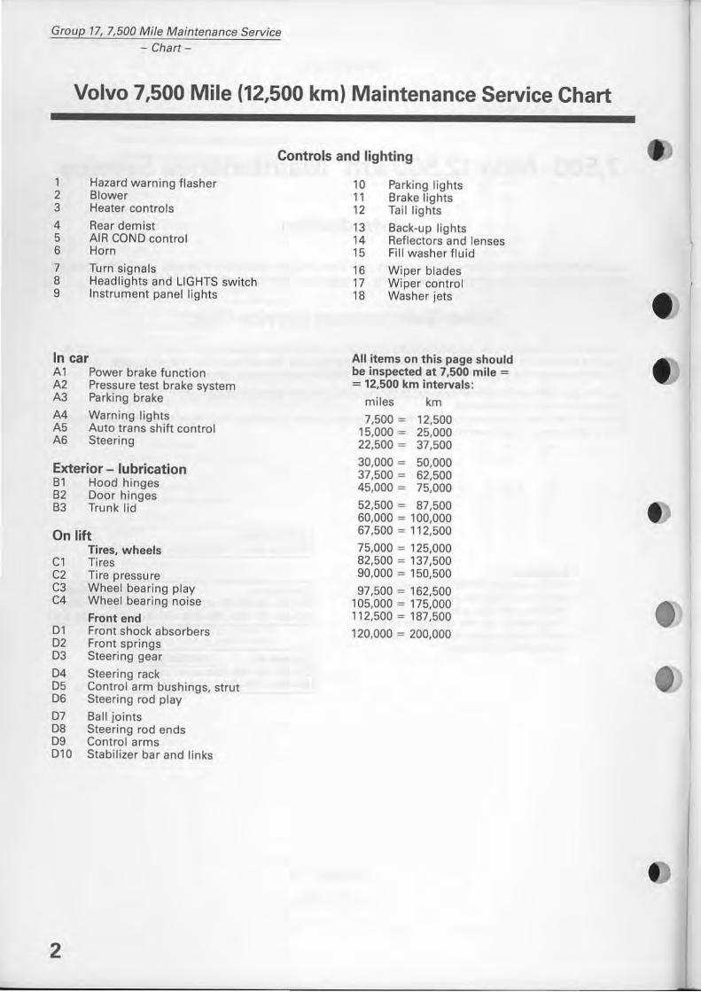
Hazard warning flasher Blower Heater controls
Rear demist AIR COND controi Horn
Turn signals Headlights and LlGHTS switch Instrument panel lights
Power brake function Pressure test brake system Parking brake
Warning lights Auto trans shift controi Steering
Exterior - lubrication 81 Hood hinges 82 Door hinges 83 Trunk lid
On lift Tires, wheels
Cl Tires C2 Ti re pressu re C3 Wheel bearing play C4 Wheel bearing noise
Front end 01 Front shock absorbers 02 Front springs 03 Steering gear
04 Steering rack 05 Controi arm bushings, strut 06 Steering rod play
07 8all joints 08 Steering rad ends 09 Controi arms 010 Stabilizer bar and links
2
Controls and lighting
10 Parking lights 11 Brake lights 12 Tail lights
13 Back-up lights 14 Reflectors and lenses 15 Fill washer fluid 16 Wiper blades 17 Wiper controi 18 Washer jets
All items on this page should be inspected at 7,500 mile = = 12,500 km intervals:
miles km
7,500 = 12,500 15,000 = 25,000 22,500 = 37,500
30.000 = 50,000 37,500 = 62,500 45,000 = 75,000
52,500 = 87,500 60,000 = 100,000 67,500 = 112,500
75,000 = 125,000 82,500 = 137,500 90,000 = 150,500
97,500 = 162,500 105,000 = 175,000 112,500 = 187,500
120,000 = 200,000
I
•
~ ~& &&~ &~~ a&& ""''' ~ ~ 4i ~ 4i ~ 4i~" ~'r-.' <:)' km (r) ~'r-.' <:)' ~v c.,' r-.' ~ ~ :y~~ ~'f\''''' (r) CO" Cb ........
.... 1/1/ 111/1/ III/II II II 1/
~a~ a~a ~~& &&& ~~(r) ~(r)~ I.?~I.? ""''' miles 1.?c.,'!'V' !:)'r-.'~' "V'c'!'.' c.,' fY' ~' "' .... ty ",...,,,,, v,{QCO ""'OJ
••• ••• ••• • •• E1 ••• ••• ••• • •• E2 ••• ••• ••• • •• E3 • • • • • • E4
••• ••• ••• ••• F1 ••• ••• ••• ••• F2
••• ••• ••• ••• F3 ••• ••• ••• • •• F4
••• ••• ••• • •• G1 ••• ••• ••• ••• G2
• • • • • • H1
• • • • • • H2 • • • • • • H3
••• ••• ••• ••• 11 ••• ••• ••• ••• 12
Group 17, 7,500 Mile Maintenance Service - Chart-
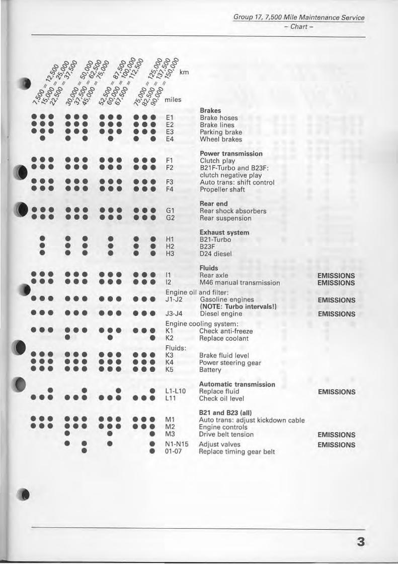
Brakes Brake hoses Brake lines Parking brake Wheel brakes
Power transmission Clutch play B21 F-Turbo and B23F: clutch negative play Auto trans: shift contra I Propeller shaft
Rear end Rear shock absorbers Rear suspension
Exhaust system B21·Turbo B23F 024 diesel
Fluids Rear axle EMISSIONS M46 manual transmission EMISSIONS
••• Engine oil and filter: ••• ••• ••• J1-J2 Gasoline engines EMISSIONS (NOTE: Turbo intervals!l ••• ••• ••• ••• J3-J4 Diesel engine EMISSIONS
••• ••• ••• Engine cooling system:
••• K1 Check anti-freeze • • • K2 Replace coolant
Fluids: ••• ••• ••• ••• K3 Brake fluid level ••• ••• ••• • •• K4 Power steering gear ••• ••• ••• ••• K5 Battery
Automatic transmission • • • • L1-L10 Replace fluid EMISSIONS ••• ••• ••• ••• L11 Check oil level
B21 and B23 (all) ••• ••• ••• ••• M1 Auto trans : adjust kickdown cable ••• ••• ••• ••• M2 Engine contrals • • • M3 Drive belt tension EMISSIONS
• • • • N1-N15 Adjust val ves EMISSIONS • • 01-07 Replace timing gear belt
3
Group 17, 7,500 Mi/e Maintenance Service - Chart-
!7:)!7:) !7:)!7:)!7:) '" '" '" a~a G ~Jr ~~~ ~~~ '1 !7:)'''V' "'''''' 45 ~'(\' <:;)' f'v'~' ~'(\'<:;)' k ::Y' tV "'::I 45 CO '\ cb-~~ :Y:::?~ m
II II II II II II II II II II II II
!7:)a~ ~~a ~a~ a~a GG45 &45G ""''' G (rj G 'I '1 lrJ'!'v' !:)' (\' lrJ' ""<:;)''\' lrJ' !'v'~' mi es '\""'rv "5"'::1'" "''''''' " ., Oj
••• ••• ••• ••• P1 ••• ••• ••• • •• P2 ••• ••• ••• ••• P3
••• ••• ••• ••• P4 ••• ••• ••• ••• P5 ••• ••• ••• ••• P6
• • • • • • P7 • • • • • • PB
• • • • • • P9
• • • • • • P10
• • • • • • P11
• • • P12
• • • P13 • • • P14 • • • P15
• • • • • • 01-016
••• ••• ••• ••• R1 ••• ••• ••• ••• R2 ••• ••• ••• • •• R3
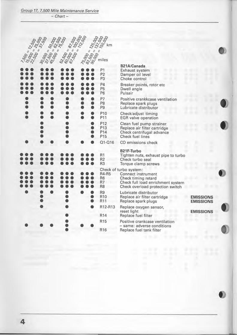
B21AJCanada Exhaust system Damper oillevel Choke controi
Breaker points, rotor etc Dwell angle Pulsair
Positive crankkcase ventilation Replace spark plugs Lubricate distributor
Check/adjust timing EGR valve operation
Clean fuel pump strainer Replace air filter cartridge Check centrifugal advance Check fue! lines
ca emissions check
B21F-Turbo Tighten nuts, exhaust pipe to turbo Check turbo sea I Torque clamp screws
••• ••• Check of turbo system:
••• • •• R4-R5 Connect instrument ••• ••• ••• • •• R6 Check timing retard ••• ••• ••• • •• R7 Check fullload enrichment system ••• ••• ••• • •• RB Check overload protection switch
• • • • • • R9 Lubricate distributor • • • R10 Replace air filter cartridge • • • R11 Replace spark plugs
• • • R12-R13 Replace oxygen sensor,
• R14 reset light Replace fuel filter
• R15 Positive crankcase ventilation • • • • • • - same: adverse conditions
• R16 Replace tuer tank filter
4
EMISSIONS EMISSIONS
EMISSIONS
• • •
• •• ••• ••• • • • • • • • • • • • •
• • • • • • • • • • • •
••• ••• • • • • • • • • • • • • • • • • • • • • •
Sl S2 S3-S4
S5 S6
S7
al a2 a3
a4 a5 a6 a7
bl-b12 cl -d7
Group 77, 7,500 M i/e Maintenance Service Chart
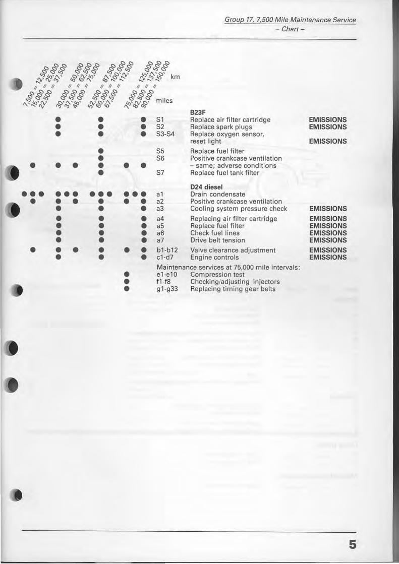
B23F Re place air filter cartridge Replace spark plugs Replace oxygen sensor, reset light
Replace fu el filte r Positive cran kease ventilation - sa me; adverse conditions Replace fu el tank filter
024 diesel Drain condensate Positive crankease ventilation Cooling system pressure check
Replacing air filter cartridge Replace fuel filter Check fuel lines Drive belt tension
Valve clearance adjustment Engine controls
EMISSIONS EMISSIONS
EMISSIONS
EMISSIONS
EMISSIONS EMISSIONS EMISSIONS EMISSIONS
EMISSIONS EMISSIONS
M aintenance services at 75,000 mile intervals: el-e l D Compression test fl-fB Checking/adjusting injectors 91-933 Replacing timing gear belts
5
Group 17, 7,500 Mile Maintenance Service - Chart -
-------- Road test ---------
E,~
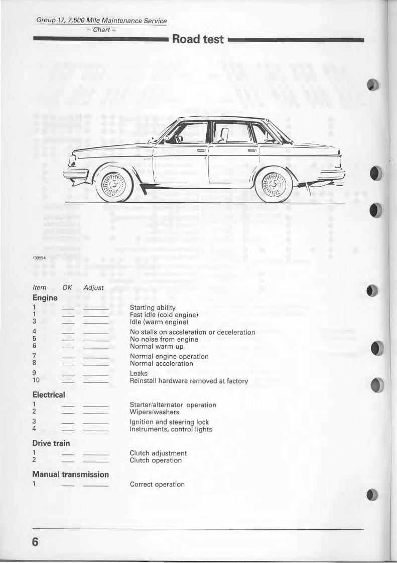
Item OK Adjust
Engine 1 1 3
4 5 6
7 8
9 10
Electrical 1 2
3 4
Drive train 1 2
Manual transmission
6
,A I,n ~
I = ', ,
~J
Starting ability Fast idle (cold engine) Idle (warm engine)
'C & = ' :
No sta lls on acceleration or deceJeration No noise from engine Normal warm up
Normal engine operation Normal acceleration
leaks Reinstall hardware removed at factory
Starteri alternatar operation Wiperslwashers
19nitjon and steering lock Instruments. controi lights
Clutch adjustment Clutch operation
Correct operation
==-- j c
J.
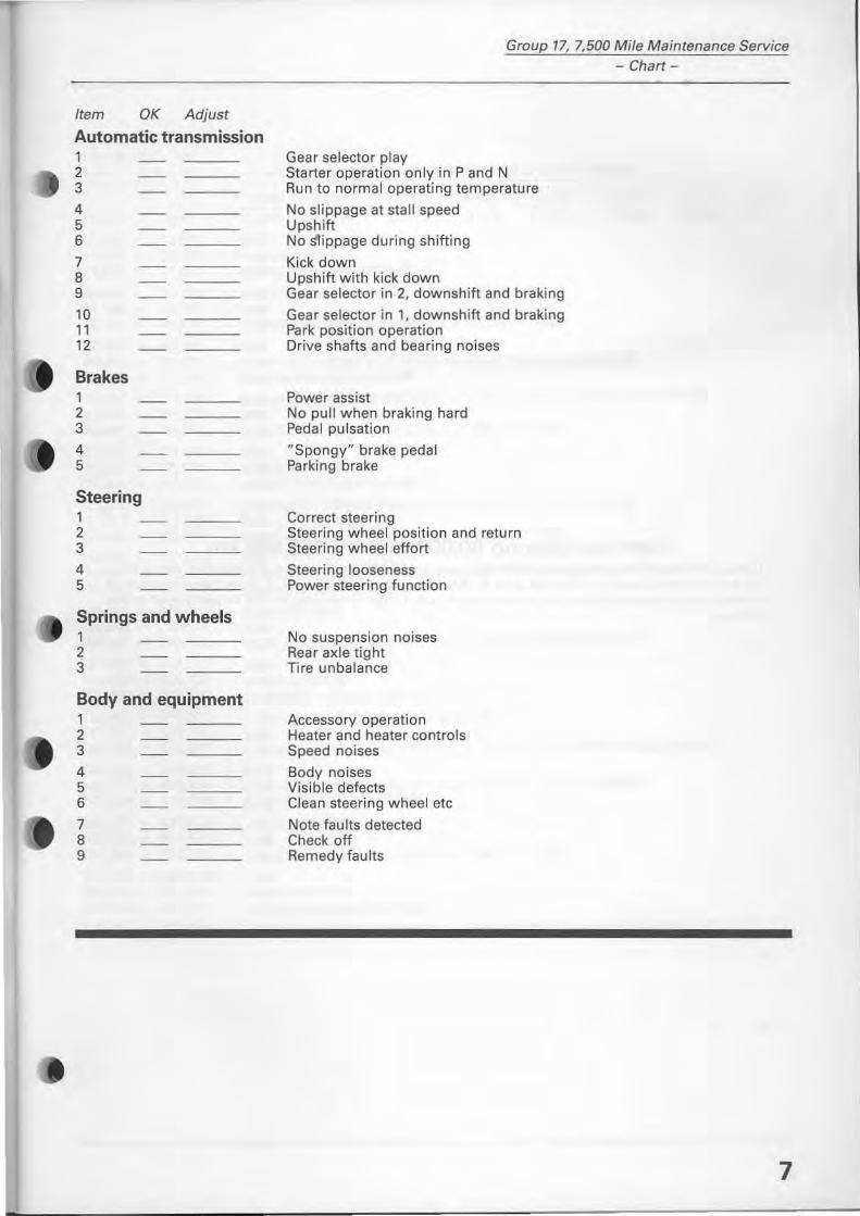
Item OK Adjust
Automatic transmission 1 2 3 4 5 6 7 B 9
10 11 12
Brakes 1 2 3
4 5
Steering 1 2 3 4 5
Springs and wheels 1 2 3
Body and equipment 1 2 3
4 5 6
7 B 9
Group 17, 7,500 Mi/e Maintenance Service - Chart-
Gear seleetor play Starter operation only in P and N Aun to normaloperating temperature
No sli ppage at stall speed Upshift No stippage during shifting
Kick down Upshift with kick down Gear selector in 2, downshift and braking
Gear seleetor in 1, downshift and braking Park position operation Drive shafts and bearing noises
Power assist No pull when braking hard Pedal pulsation
"Spongy" brake pedal Parking brake
Correct steering Steering wheel position and return Steering wheel eftort
Steering looseness Power steering function
No suspension noises Rear axle tight Tire unbalance
Accessory operation Heater and heater controls Speed noises
Body noises Visible defects Clean steering wheel etc
Note faults detected Check off Remedy faults
7
Group 17, 7,500 Mile Maintenance Service - Chart-
8
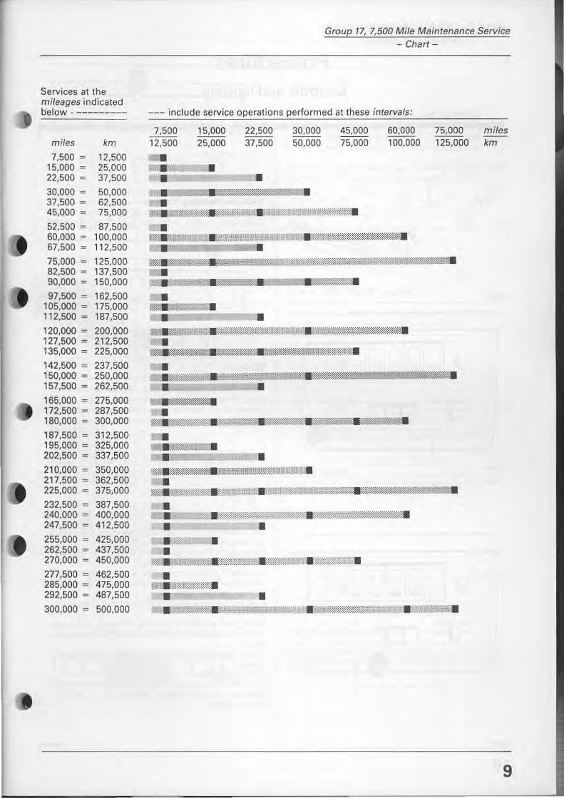
Services beyond 90,000 miles = 150,000 km The service charts list m ileage up to 90,000 miles = 150,000 km. Space and readability sets a limit. On the following page is a list that goes to 300,000 miles = 500,000 km. It cross references actual mileage when a service should be performed and what interval services should be performed at that mileage.
Services at the mileages indicated b'elow . ---------
miles km
7,500 ~ 12,500 15,000 ~ 25,000 22,500 ~ 37,500
30,000 ~ 50,000 37,500 ~ 62,500 45,000 ~ 75,000
52,500 ~ 87,500 60,000 ~ 100,000 67,500 ~ 112,500
75,000 ~ 125,000 82,500 ~ 137,500 90,000 ~ 150,000
97,500 ~ 162,500 105,000 ~ 175,000 112,500 ~ 187,500
120,000 ~ 200,000 127,500 ~ 212,500 135,000 ~ 225,000
142,500 ~ 237,500 150,000 ~ 250,000 157,500 ~ 262,500
165,000 ~ 275,000 172,500 = 287,500 180,000 ~ 300,000
187,500 ~ 312,500 195,000 ~ 325,000 202,500 ~ 337,500
210,000 ~ 350,000 217,500 ~ 362,500 225,000 ~ 375,000
232,500 ~ 387,500 240,000 ~ 400,000 247,500 ~ 412,500
255,000 ~ 425,000 262,500 ~ 437,500 270,000 ~ 450,000
277,500 ~ 462,500 285,000 ~ 475,000 292,500 ~ 487,500
300,000 ~ 500,000
Group 17, 7,500 Mi/e Maintenance Service - Chart-
--- include service operations performed at these intervals:
7,500 12,500
15,000 25,000
-22,500 37,500
• •
30.000 50,000
~~'am:-0lt~i;ll;:mj;:;; !;OW.
•
45,000 75,000
~ .. :m1t:m%.-mmoow.wrm:Wf<W~:WJ.:mff{.
60,000 100,000
• ~tWJWjt%f"'\ili1:illtt~~MMMU~llir;gftWW;fllit%.
75,000 125,000
_ _ JW __ IWii1W:'
• wal;;" ::: ; ; .mg~:Xll[:; :[:;':.~.
• _.-• •
m;.~W _ _ 1~@",'m"" w".,-".f@,:mmM", _i1Wm~-ifu..'%,,""'tf~
• mt\E@:@i$WiH:-W&%*l.~.;.%t_~.
• ~_~~~W~jl:_;~.
_ I];;]'i_
• =-@!;:'~4t..mm_.I:mw;w~$Wi_.
• $W~r*%: .. tmm;.%mtWf:lli't$W:Wffi.
• ma~W::1r~,'amtk1illk",*H1:mM'i@m-~ .. m:~mwru©lil~.
• ~.W:if:ft&; "~>W0.;."1~.~;amru::mm:_
• • lWi. _ lI
• 't.%.1%fNmmt::.;f1rJ:::-:fW1.*~W:.Wlli&?a.
• j~:t®mBWtm.
• • ~ji(t0.l'lli'fu-:..~7$~:i::i:~'·.Eifu;;;m:t:'~.~.
miles km
9
Group 17, 7,500 Mile Maintenance Service - Cantrals and lighting -
Procedures Controls and lighting
""" r
J
130090
r- -----------
~~ ~~~~ iJ GJ , \ \~ H -I-I "'6 ")1 ;,.' .. :
130691
10
J
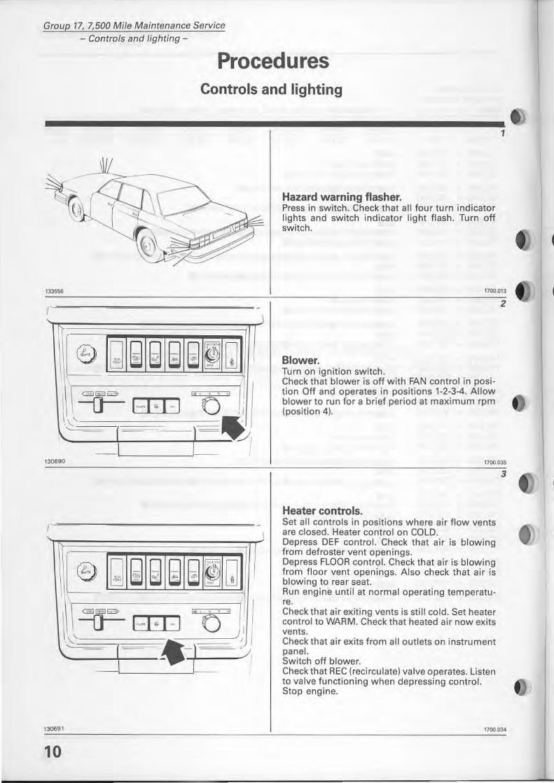
Hazard warning flasher. Press in switch. Check that all four turn indicator lights and switch indicator light flash. Turn off switch.
l
1100.013
Blower. Turn on ignition switch. Check that blower is off with FAN controi in position Off and operates in positions 1-2-3-4. Allow blower to run for a brief period at maximum rpm (position 4).
2
1700.035
Heater controis. Set all controls in positions where air flow vents are clased. Heater controi on COLO. Oepress OEF controI. Check that air is blowing from defroster vent openings. Depress FLODR controI. Check that air is blowing from fl oor vent openings. Also check that air is blowing to rear seat. Run engine until at normaloperating temperatur •. Check that air exiting vents is still cold. Set heater controi to WARM. Check that heated air nowexits vents. Check that air exits from all outlets on instrument panel. Switch off bJower. Check that REC (recirculate) valve operates. Listen to valve functioning when depressing controI. Stop engine.
3
1700.03-4
@ ~ ~ ~ ~ ~ ~ Q
\\,,~ I. , . , ,I
(·-1·1-1 O , ..
, 30610
"'ö " \ --0--""''''''''' ( ·~ I · I ·· I . " ,
1306 ' ,
",'"
I
I , . I
Group 17, 7,500 Mile Maintenance Service Cantrals and lighting-
4
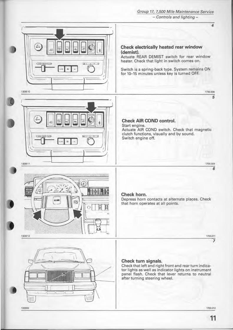
Check electricallv heated rear window (demist). Actuate REAR DEMIST switch for rear window heater. Check that light in switch comes on.
Switch is a spring-back type. System remains ON for 10-15 minutes uniess key is turned OFF.
1100.008
Check AIR COND control. Start engine. Actuate AIR COND switch. Check that magnetic clutch functions, visually and by sound. Switch engine off.
5
1100.009
Check horn. Depress horn contacts at alternate places. Check that horn operates at all points.
6
,700,011
Check tum signals. Check that left and right front and rear turn indicator lights as weil as indicator lights on instrument panel flash. Check that lever returns to neutral af ter turning steering wheel.
7
1100.012
11
Group 17, 7,500 Mi/e Maintenance Service Controls and lighting -
/
133207
133557
133558
12
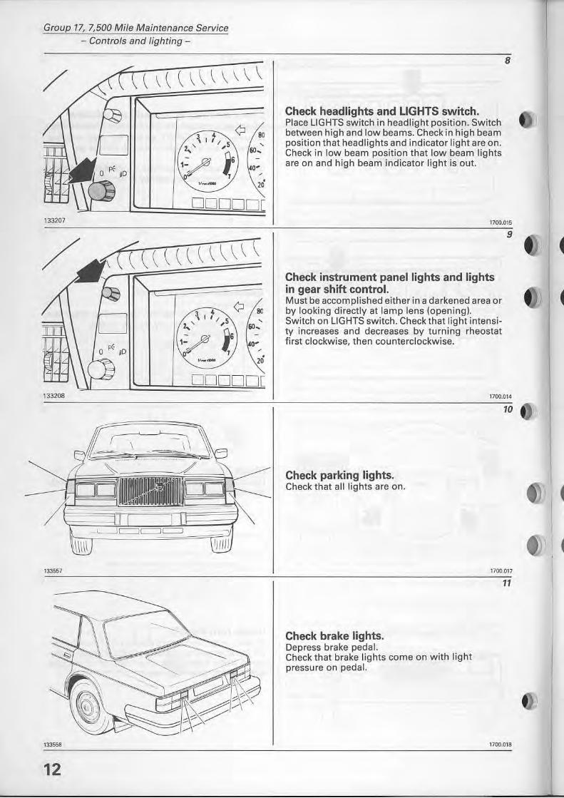
Check headlights and LIGHTS switch. Place lIGHTS switch in headlight position. Switch between high and low beams. Check in high beam position that headlights and indicator light are on. Check in low beam position that low beam lights are on and high beam indicator light is out.
8
1700.015
Check instrument panellights and lights in gear shiit control. Must be accomplished either in a darkened area or by looking directly at lam p lens (opening). Switch on lIGHTS switch. Check that light intensity increases and decreases by turning rheostat first clockwise, then counterclockwise.
9
1700.014
Check parking lights. Check that all lights are on.
Check brake lights. Depress brake pedal. Check that brake lights come on with light pressure on pedal.
10
1700.017
11
1700.018
l
-----.
133571)
Group 17, 7,500 Mi/e Maintenance Service - Contrals and lighting -
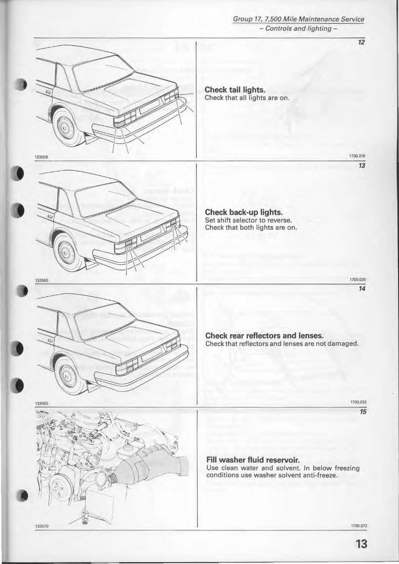
Check tail lights. Check that alllights are on.
Check back-up lights. Set shift selector to reverse. Check that both lights are on.
Check rear reflectors and lenses.
12
1700.019
13
170Cl.020
14
Check that reflectors and lenses are not damaged.
1700.052
15
FiII washer fluid reservoir. Use c1ean water and solvent. In below freezing conditions use washer solvent anti-freeze.
1700.012
13
Group 17, 7,500 Mile Maintenance Service - Controls and lighting -
13 1425
1240 13
('--- - 6-
"""
14
.11 ~ l ~ I
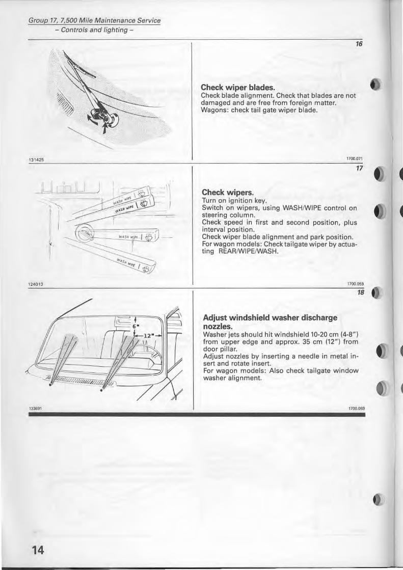
Check wiper bl.des. Check blade alignment. Check that bia des are not damaged and are free from foreign matter. Wagons: check tail gate wiper blade.
16
1700.071
Check wipers. Turn on ignition key.
17
Switch on wipers, using WASHIWIPE controi on steering column. Check speed in first and second position, plus interval position. Check wiper blade alignment and park position. For wagon modeis: Check tailgate wiper by actuating REARlWIPEIWASH.
Adjust windshield w.sher disch.rge nozzles.
1700.059
18
Washer jets should hit windshield 10-20 cm (4-8") from upper edge and approx. 35 cm (12") from door pillar. Adjust nozzles by inserting a needle in metal insert and rotate insert. For wagon modeis: Also check tailgate window washer alignment.
1700.069
",'"
LOIrI, 20 seconds
133708
133200
Group 17, 7,500 Mile Maintenance Service -/ncar-
In ear Service every 7,500 miles = 12,500 km
HIGH, 5 second s
Al
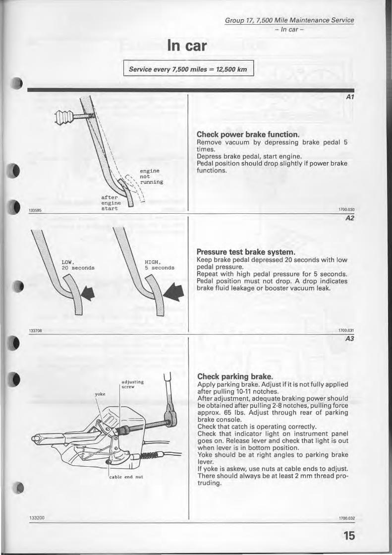
Check power brake function. Remove vacuum by depressing brake pedal 5 times. Depress brake pedal, start engine. Pedal position should drop sl ightly if power brake tunctions.
1700.030
A2
Pressure test brake system. Keep brake pedal depressed 20 seconds with low pedal pressure. Repeat with high pedal pressure for 5 seconds. Pedal position must not drop. A drop indicates brake fluid leakage or booster vacuum leak.
1700.031
A3
Check parking brake. Apply parking brake. Adjust if it is notfully applied atter pulling 10-11 notches. After adjustment, adequate braking power should be obtained after pulling 2-8 notches, pulling force approx. 65 Ibs. Adjust through rear of parking brake con so le. Check that catch is operating correctly. Check that indicator light on instrument panel goes on. Release lever and check that light is out when lever is in bottom position. Voke should be at right angles to parking brake lever. If yoke is askew, use nuts at cable ends to adjust. There should always be at least 2 mm thread protruding.
1100.032
15
Group 17, 7,500 Mi/e Maintenance Service -In car-
.... .. ..
16
A4
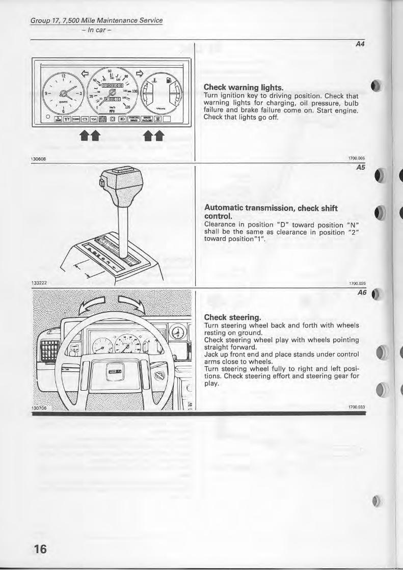
Check warning light •. Turn ignition key to driving position. Check that warning lights for charging, oH pressure, bulb failure and brake failure come on. Start engine. Check that lights go off .
Automatic transmission, check shift controI.
1700.006
A5
Clearance in position "D" toward position "N" shall be the same as clearance in position "2" toward position"1 " .
1700.026
A6
Check steering. Turn steering w heel back and forth with wheels resting on ground. Check steering wheel play w ith wheels pointing straight forward. Jack up front end and place stands under controi arms close to wheels. Turn steering wheel fully to right and left posi tions. Check steering eftort and steering gear for play.
1700.033
1335!l6
118551
118558
133598
Group 17, 7,500 Mife Maintenance Service Exterior, fubrication-
Exterior - lubrication Service every 7,500 miles = 12,500 km
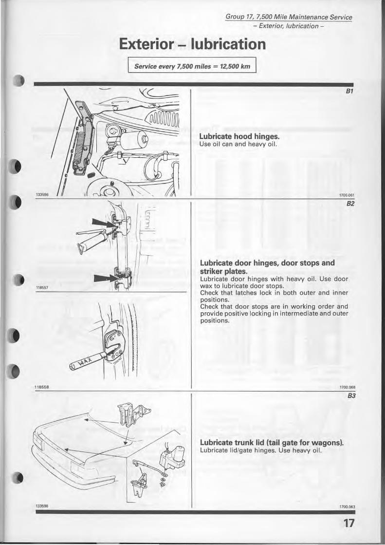
Lubricate hood hinges. Use oil can and heavy oil.
Lubricate door hinges, door stops and striker plates.
BI
1100.061
B2
Lubricate door hinges with heavy oil. Use door wax to lubricate door stops. Check that latches lock in both outer and inner positions. Check that door stops are in working order and provide positive locking in intermediate and outer positions.
1100.068
Lubricate trunk lid (tail gate for wagon si. Lubricate lid/gate hinges. Use heavy oH.
B3
1100.063
17
Group 17, 7,500 Mile Maintenance Service
- Tires, wheels -
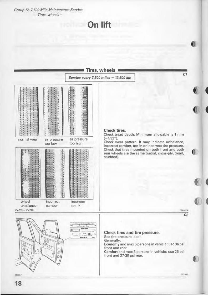
normal wear
;:n= "
wheel unbalance
104769 .. 104770
""" 18
:- ;
! "
j , i 'r i , :t\ J
~ ~ " ,.- ,: , ~ , ,
air pressure too low
incorrect camber
:'
On lift
Tires, wheels CI
Service every 7,500 miles = 12,500 km
air pressure too high
incorrect toe-in
Check tires, Check tread depth. Minimum al10wable is 1 mm 1=1/32"), Check wear pattern. It may indicate unbalance, incorrect camber, toe-in or incorrect tire pressure. Check that tires mounted on both front and both rear wheels are the same {radial, cross-ply, tread, studdedl.
Check tires and tire pressure. See tire pressure label. Generally:
1100.106
C2
Economy and max 5 persons in vehicle: use 36 psi front and rear. Comfort and max 3 persons in vehicle: use 26 psi front and 27-30 psi rear.
1700.065
124029
118561
"""
,,,, ..
Group 17, 7,500 Mile Maintenance Service - Front end-
C3
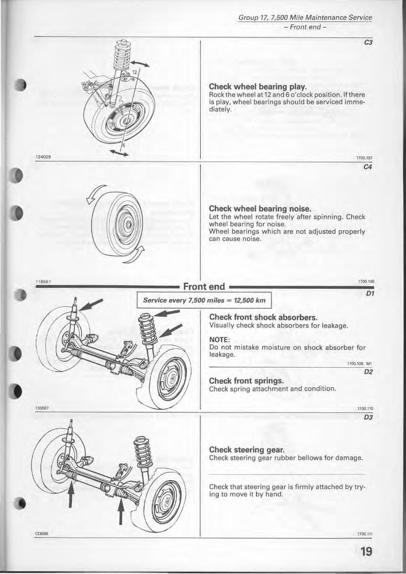
Check wheel bearing play. Rock the wheel at 12 and 6 o'clock position. If there is play, wheel bearings should be serviced immediately.
1100,107
C4
Check wheel bearing noise. Let the wheel rotate freely after spinning. Check wheel bearing for noise. Wheel bearings which are not adjusted properly can cause noise.
1700.108
DI Service every 7,500 miles = 12,500 km
Check front shock absorbers. Visually check shock absorbers for leakage.
NQTE: Do not mistake moisture on shock absorber for leakage.
1700.109. M1
D2 Check front springs. Check spring attachment and condition.
1700.110
D3
Check steering gear. Check steering gear rubber bellows for damage.
Check that steering gear is firmly attached by trying to move it by hand.
1100.111
19
Group 17, 7,500 Mile Maintenance Service - Front end-
124031
118584
\
124030
118564
20
04
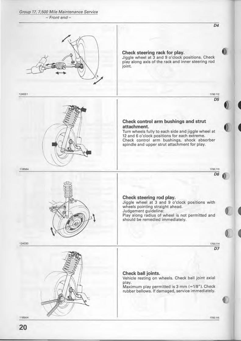
Check steering rack for play. Jiggle wheel at 3 and 9 o'clock positions. Check playalong axis of the rack and inner steering rod joint.
Check controi arm bushings and strut attachment.
1700.112
05
Turn wheels fully to each side and jigg le wheel at 12 and 6 o'clock positions for each extreme. Check controi arm bushings, shock absorber spindle and upper strut attachment for play.
1700.113
06
Check steering rod play. Jiggle wheel at 3 and 9 o'clock positions with wheels painting straight ahead. Judgement guideline: Playalong radius of wheel is not permitted and should be remedied immediately.
1700.114
07
Check ball joints. Vehicle resting on wheels. Check ball joint axial play. Maximum play permitted is 3 mm (=1 /8"). Check rubber bellows. If damaged, service immediately.
1700.115
'18555
118566
118567
I
"
Group 77, 7,500 Mi/e Maintenance Service - Front end-
08
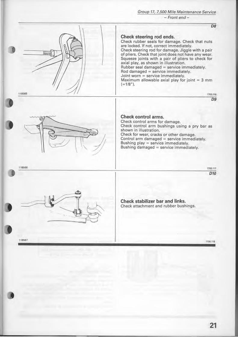
Check steering rcd ends. Check rubber seals for damage. Check that nuts are locked. If not, correct immediately. Check steering rad for damage. Jiggle with a pair of pliers. Check that joint does not have any wear. Squeeze joints with a pair of pliers to check for axial play, as shown in illustration. Rubber sea I damaged = service immediately. Rad damaged = service immediately. Joint worn = service immediately. Maximum allowable axial play for joint = 3 mm (~1I8"1.
1700.116
09
Check controi arms. Check controi arms for damage. Check controi arm bushings using a pry bar as shown in illustration. Check for wear, cracks or other damage. Contral arm damaged = service immediately. Bushing play = service immediately. Bushing damaged = service immediately.
Check stabilizer bar and links. Check attachment and rubber bushings.
1700.117
010
1700.118
21
Group 17, 7,500 Mile Maintenance Service - Brakes-
Brakes Service every 7,500 miles = 12,500 km
EXCEPT AS STATED
El
118507
129 396
/ \
129570
118612
22
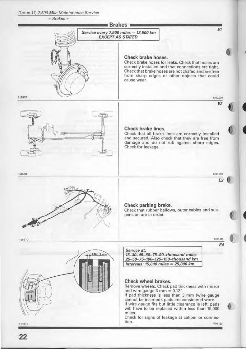
Check brake hoses. Check brake hoses for leaks. Check that hoses are correctly installed and that connections are tight. Check that brake hoses are not chafed and are free from sharp edges or other objects that could cause wear.
E2
Check brake lines. Check that all brake lines are correctly installed and secured. Also check that they are free from damage and do not rub against sharp edges. Check for leakage.
1700.093
E3
Check parking brake. Check that rubber bellows. outer cables and suspension are in order.
Service at: 15-30-45-60-75-90-thousand miles 25-50-75-100-125-150-thousand km Intervals: 15,000 miles 25,000 km
Check wheel brakes.
1700.119 e E4
Remove wheels. Check pad thickness with mirror and wire gauge 3 mm = 0.12". If pad thickness is less than 3 mm (wire gauge cannot be inserted), pads are considered worn. If wire gauge fits but little clearance is left, pads will have to be replaced within less than 15,000 miles. Check for signs of leakage at caliper or connection. 1100.120
Group 17, 7,500 Mile Maintenance Service - Power transmission -
Power transmission
Service every 7,500 miles = 12,500 km
Diesel.
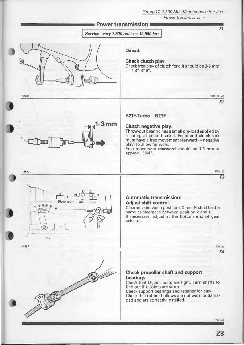
Check clutch play. Check free play of clutch fork. It should be 3-5 mm = 1/8"-3/16".
Fl
133689 1700.121. MI
, I I , , ,
133690
j '
118 571
D 2
~ FIoor shift .~ .040
F2
B21F-Turbo+ B23F.
Clutch negative play. Throw-out bearing has a small pre-Ioad applied by a spring at pedal bracket. Pedal and clutch fork must have a free movement rearward (=negative play) to allow for wear. Free movement rearward should be 1-3 mm = approx. 5/64".
1700.122
Automatic transmission: Adjust shift contro!. Clearance between positions D and N shall be the same as clearance between position 2 and 1. If necessary, adjust at the bottom end of gear selector.
F3
1700.123
Check propeller shaft and support bearings.
F4
Check that U-joint balts are tight. Turn shafts to find out if U-ioints are worn. Check support bearings and retainer for play. Check that rubber bellows are not worn or damaged and are correctly installed.
23
Group 17, 7,500 Mife Maintenance Service - Rear end-
Rear end
Service every 7,500 miles = 12,500 km
Gl G2
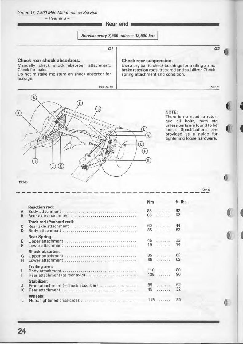
Check rear shock absorbers. Check rear suspension. Manually check shock absorber attachment. Check for leaks. Do not mistake moisture on shock absorber for leakage.
Use a pry bar to check bushings for traiHng arms, brake reaction rads, track rad and stabilizer. Check spring attachment and conditian.
1700.125. MI 1700.128
NOTE: There is no need to retorque all balts. nuts etc uniess parts are found to be loose. Specifications are provided as a guide for tighte ni ng loose hardware.
1100,489 -----------------------------------
Reaction rad: A Bodyattachment ..... ........• . . o ••• • • •••••••• • ••••••
B Rear axle attachment ........ .. . ................ . ... . .
Track rad (Panhard rad): C Rear ax le attachment .......... . ......•... .. . • ........ D Bodyattachment .. ............... .. . ..... o' • • • .••••••
Rear Spring: E Upper attachment ........ ..... .....•...... . ...... . ... F Lower attachment ........... ... .. ..... . .. . . .. . ... . . •.
Shock absarber: G Upper attachment ............. . . .......... . .... . . o · ••
H Lower attachment ....... . .. . . .. . . . ... .. . •. ....... • ...
Trailing arm: I Bodyattachment . ........... . ......... . ........ • . . . .. F Rear attachment (at rear axle) . .. ..... ................ .
Stabilizer: J Front attachment (= shock absorberl ..... ...... . ... ... . K Rear attachment .................. . ... ... • .....
Wheels: L Nuts, tightened criss-cross ............ . ... . . . ... ... • ..
24
Nm
85 ...... . 85
60 85 ...... .
45 ...... . 19
85 ...... . 85
110 125
85 ...... . 45
115
ft.lbs.
62 62
44 62
32 14
62 62
80 90
62 32
85
Service at: 15-30-45-60-75-90-thousand miles 25-50-75-100-125-150-thousand km IntervaJs: 15,000 miles - 25,000 km
•• •
129575
EMISSIONS
Group 17, 7,500 Mi/e Maintenance Service
- Exhaust system - Rear axle, manual transmission -
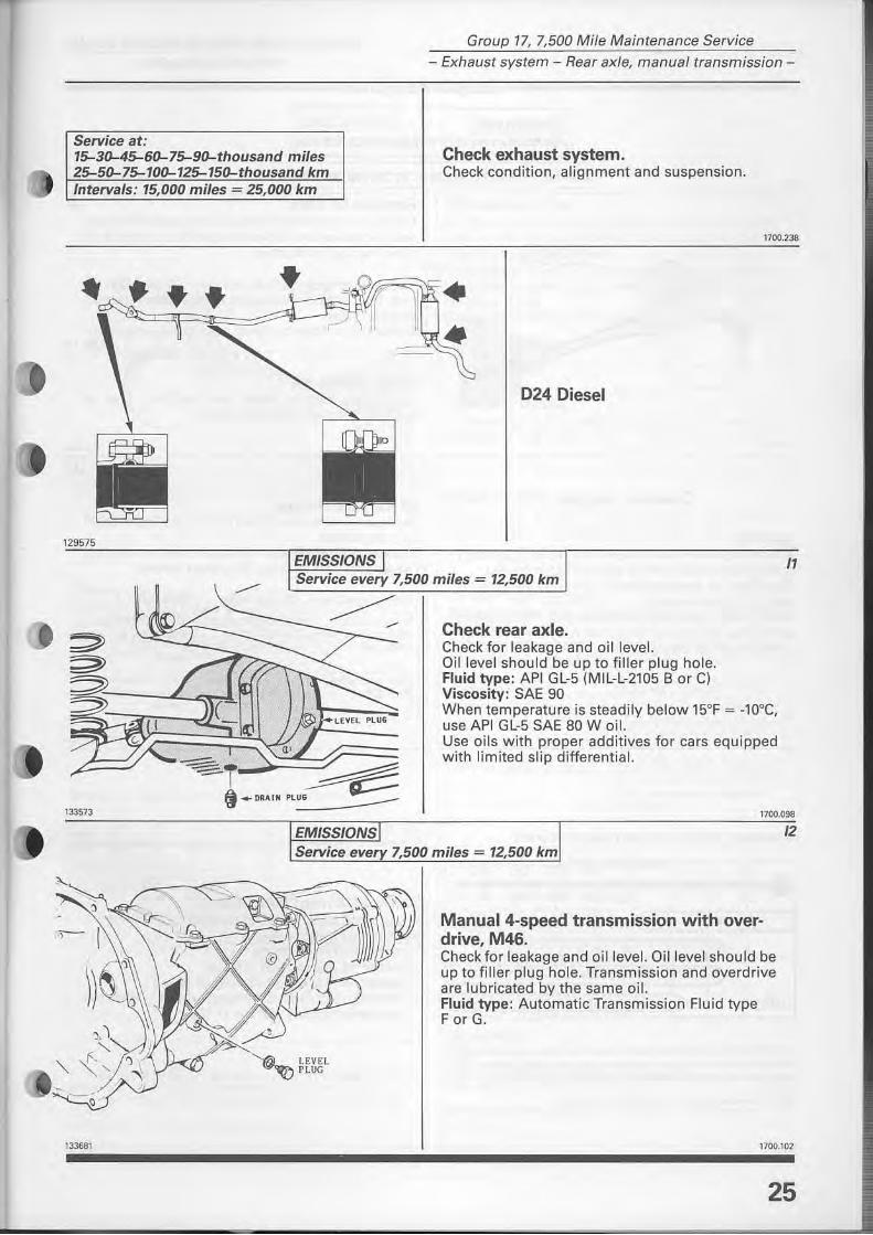
Check exhaust system. Check condition, alignment and suspension.
1700 238
024 Diesel
11 Service every 7,500 miles = 12,500 km
133681
EMISSIONS
Check rear axle. Check for leakage and oillevel. Qillevel should be up to filler plug hale. Fluid type: API GL-5 (MIL-L-2105 B or Cl Viscosity: SAE 90 When temperature is steadily below 15°F"" _lOoe , use API GL-5 SAE 80 W oil. Use oils with proper additives for cars equipped with limited slip differential.
1700.098
12 Service ever 7,500 miles = 12,500 km
'la_ LEVEl '""~ PlUG
Manual 4-speed transmission with overdrive, M46. Check for leakage and oillevel. Oillevel shou ld be up to filler plug hale. Transmission and overdrive are lubricated by the same oH. Fluid type: Automatic Transmission Fluid type F or G.
1700.102
25
Group 17, 7,500 Mife Maintenance Service
- Engine oil and filter-
-----------Gasolineengines----------_
EMISSIONS I Service every 7,500 miles = 12,500 km
INOTE: Turbo frequency, twice as often.1
2903 ......-?1~H-----
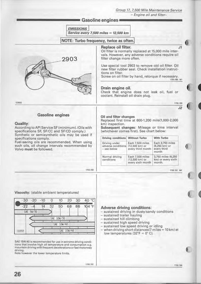
Replace oil filter. JI Oil filter is normally replaced at 15,000 mile intervals. However, any adverse conditions require oil filter change more often .
Use special tool 2903 to rem ove old oil filter. DB new filter rubber sea I. Check installation instructians on filter. Screw on oil filter by hand, retorque if necessary.
1700.189. MI
Drain engine oil. Check that engine does not leak oil, fuel or coolant. Reinstall oil drain plug.
113682 1700.188
Gasoline engines
Quaiity: According to API Service SF (minimum). (Oi ls with specifications SE SF/CC and SF/CD comply.) Synthetic or semisynthetic oils may be used if specifications comply. Fuel-saving oils are recommended. When using such oils, oil change intervals recommended by Volvo must be followed.
1700.190
Viscosity: {stable ambient temperatures}
SAE 15W/40 is recommended foruse in extremedriving condi· tions that involve high oil temperature and consumption e.g. mountain driving with freq uent decelerations or fast motorway driving. Note however the lower temperature limits.
1700.192
26
J2
Oil and filter changes Replaced tirst time at 600-1,200 mile{1,OOO-2,000 km) inspection. Subsequent changes: Mileage or time interval (whichever comes tirst). See chart below:
Driving conditions Without Turbo With Turbo
Driving under Each 7,500 miles Each 3,750 miles adverse conditions (12,500 km) or (6,250 km) or - see below every third month every third
month
Normal driving Each 7,500 miles 3,750 miles (6,250 conditions (12,500 km) or km) or every sixth
every sixth month month.
1700.197 MI
Adverse driving conditions: - sustained driving in dusty/sandy conditions - sustained trailer hauling - sustained hill climbing - sustained high speed driving - sustained low speed driving or idling - when driving shortdistances(7 miles = 10 km) at
low temperatures (32°F = 00 C).
1700.198
Group 17, 7,500 Mife Maintenance Service - Engine oif and fifter-
___________ Diesel engine ----------
EMISSIONS I Service every 7,500 miles = 12,500 km
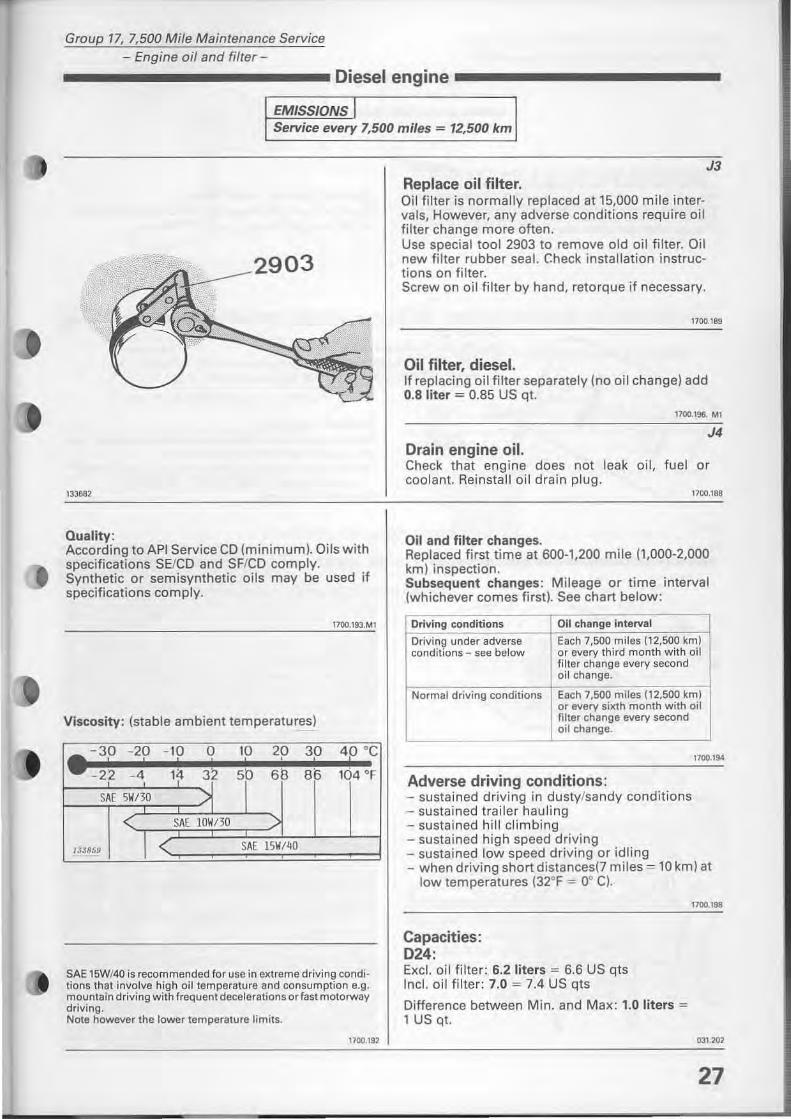
J3 Replace oil filter. Oi1 filter is normally replaced at 15,000 mile intervals, However, any adverse conditions require oH filter ehange more often. Use special tool 2903 to rem ove old oH filter. Oil new filter rubber seal. Check installation instructians on filter. Screw on oil filter by hand, retorque if necessary.
1700.189
Oil filter, diesel. If replacing oil filter separately (no oil change) add 0.8 liter = 0.85 US qt.
1100.196. MI
J4 Drain engine oil. Check that engine does not leak oil, fuel or eoolant. Reinstall oil drain plug.
133682 1700.188
Quaiity: According to API Service CD (minimum). Oils with specifications SE/CD and SF/CD comply. Synthetic or semisynthetie oBs may be used if specifieations eomply.
17oo.193.Ml
Viscosity: (stable ambient temperatures)
-30 -20 • I 1
- 10 O I I
30 !
40 °C !
5b 68 86 14 32 -22 -4
SAE 5\11/30
SAE 101//30
lJJB5!1 SAE 15\11/'10
SAE 1SWf40 is recommended for use in e)(treme driving conditions that involve high oi! temperature and consumption e.g. mountai n d riving with freq uent decelerations or fast motorway driving. Note however the lower temperature limits.
1700.192
Oil and filter changes. Replaced tirst time at 600-1.200 mile (1,000-2,000 km) inspection. Subsequent changes: Mileage or time interval (wh ichever comes first). See chart below:
Driving conditions Oil change interval
Driving under adverse Each 7,500 miles (12,500 km) conditions - see below or every third month with oil
filter change every second oil change.
Normal driving conditions Esch 7,500 miles (12,500 km) or every sixth month with oil filter change every second oil chsnge.
1700.1901
Adverse driving conditions: - sustained driving in dusty/sandy eonditions - sustained trailer hauling - sustained hill climbing - sustained high speed driving - sustained low speed driving or idling - when driving short distanees(7 miles = 10 km) at
low temperatures (32°F = 0° C).
Capacities: 024: Excl. oil filter: 6.2 liters = 6.6 US qts Inel. oil fi lter: 7.0 = 7.4 US qts
Difference between Min. and Max: 1.0 liters = 1 US qt.
1700.198
1)31.202
27
Group 17, 7,500 Mile Maintenance Service - Fluids-
---------- Engine cooling system ---------Kl Service every 7,500 miles = 12,500 km
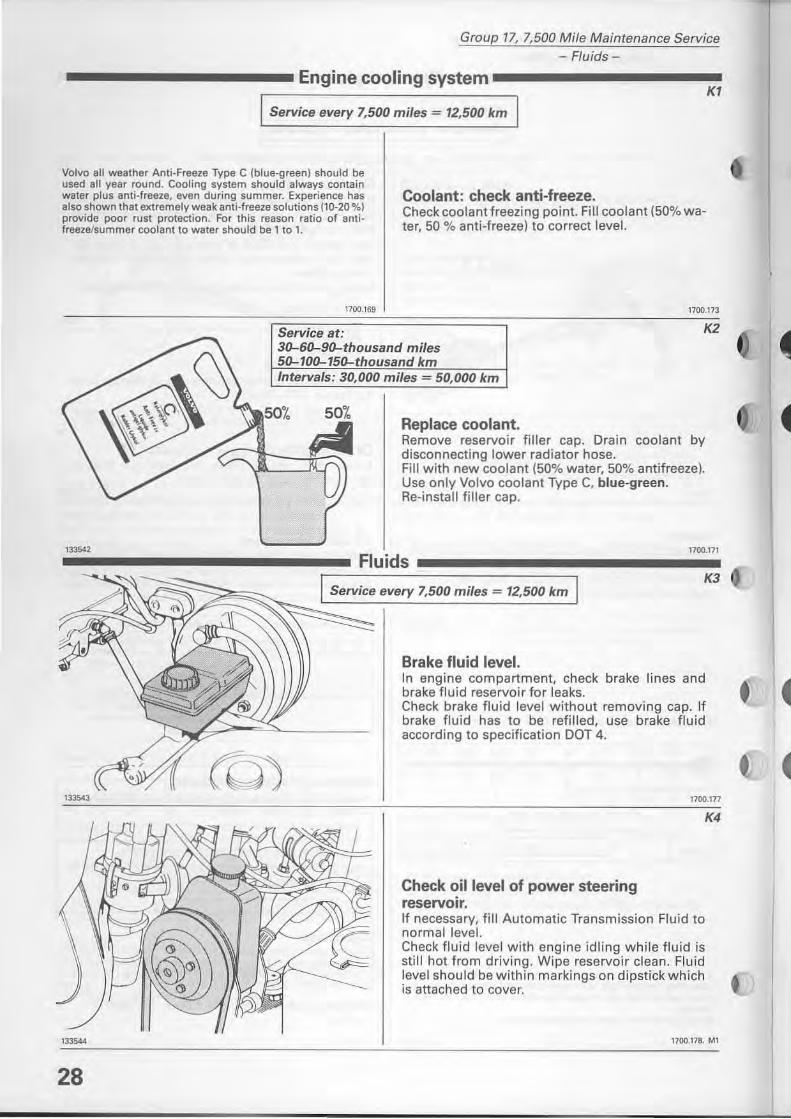
Volvo aU weather Anti·Freeze Typa C (blue·green) should be used all year round. Cooling system should always contain water plus anti-freeze, even during summer. Experience has also shown that extremely weak anti-freeze solutions (10-20 %) provide paor rust protection. For this reason ratio of antifreeze/summer coolan! to water should be 1 to l.
Coolant: check anti-freeze. Check coolant freezing point. Fil! coolant (50% water, 50 % anti-freezel to correct level.
133542
133544
28
1700.169 1700.173
Service at: 30-60-90-thousand miles 50-100-150-thousand km
K2
Intervals: 30,000 miles = 50,000 km
50% Replace coolant. Remove reservoir filler cap. Orain coolant by disconnecting lower radiator hose. Fil! with new coolant (50% water, 50% antifreezel. Use only Volvo coolant Type C, blue-green. Re-install filler cap.
1700.171
Fluids K3
Service every 7,500 miles = 12,500 km
Brake fluid level. In engine compartment, check brake lines and brake fluid reservoir for leaks. Check brake fluid level without removing cap. If brake fluid has to be refilled, use brake fluid according to specifi cation DDT 4.
1100.177
K4
Check oillevel of power steering reservoir. If necessary, fill Automatic Transmission Fluid to normalleveI. Check fluid level with engine idling while fluid is still hot from driving. Wipe reservoir dean. Fluid level shou ld be within markings on dipstick which is attached to cover.
17oo.17B. Ml
Group 17, 7,500 Mile Maintenance Service - Replacing automatic transmission fluid-
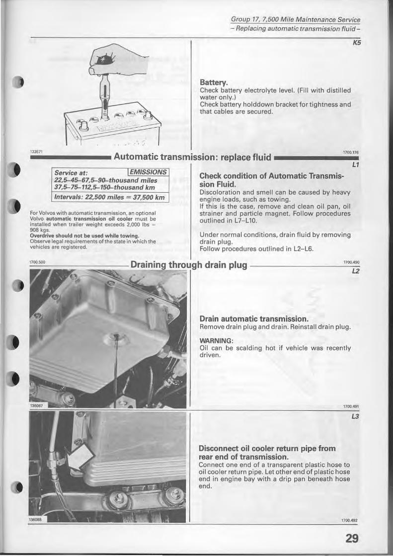
Batterv· Check battery electrolyte level. (FBI with distilled water only.) Check battery holddown bracket for tightness and that cables are secured.
K5
133571 1700.176 ------__ Automatic transmission: replace fluid _______ _
Service at: I EMISSIONS 22,>45-67,>90-thousand miles 37,5-15-112,5-150-thousand km
Intervals: 22,500 miles - 37,500 km
For Volvos with automalic t ransmission, an optional Volvo automatie transmission oi! eooler must be installed when trailer weight exceeds 2,000 Ibs = 908 kgs. Ovardrive should not be usad while towing . Observe legal requirements of the state in which the vehicles are registered.
Check conditian of Automatic Transmission Fluid. Discoloration and smell can be caused by heavy engine loads, such as towing. If this is the case, rem ove and clean oil pan, aB strainer and particie magnet. Follow procedures outlined in Ll-L 10.
Under normal conditions, drain fluid by removing drain plug. Follow procedures outlined in L2-L6.
LI
~"OO~·"~"iiiii~=:;;;;;;";;;C;;- .!:D!ra!!.i!!n!.!.in!!g!!..!t~h~ro~lugh drain plug -------- --""=00==;';
Drain automatic transmission. Remove drain plug and drain. Reinstall drain plug.
WARNING: Oil can be scaldi ng hot if vehicle was recently driven.
1700.491
Disconnect oil cooler return pipe from rear end of transmission. Connect one end of a transparent plastic hose to oH coole r return pipe. Let other end of plastic hose end in engine bay with a drip pan beneath hose end.
L3
1700_492
29
Group 17, 7,500 Mi/e Maintenance Service - Replacing automatic transmission fluid-
136102
30
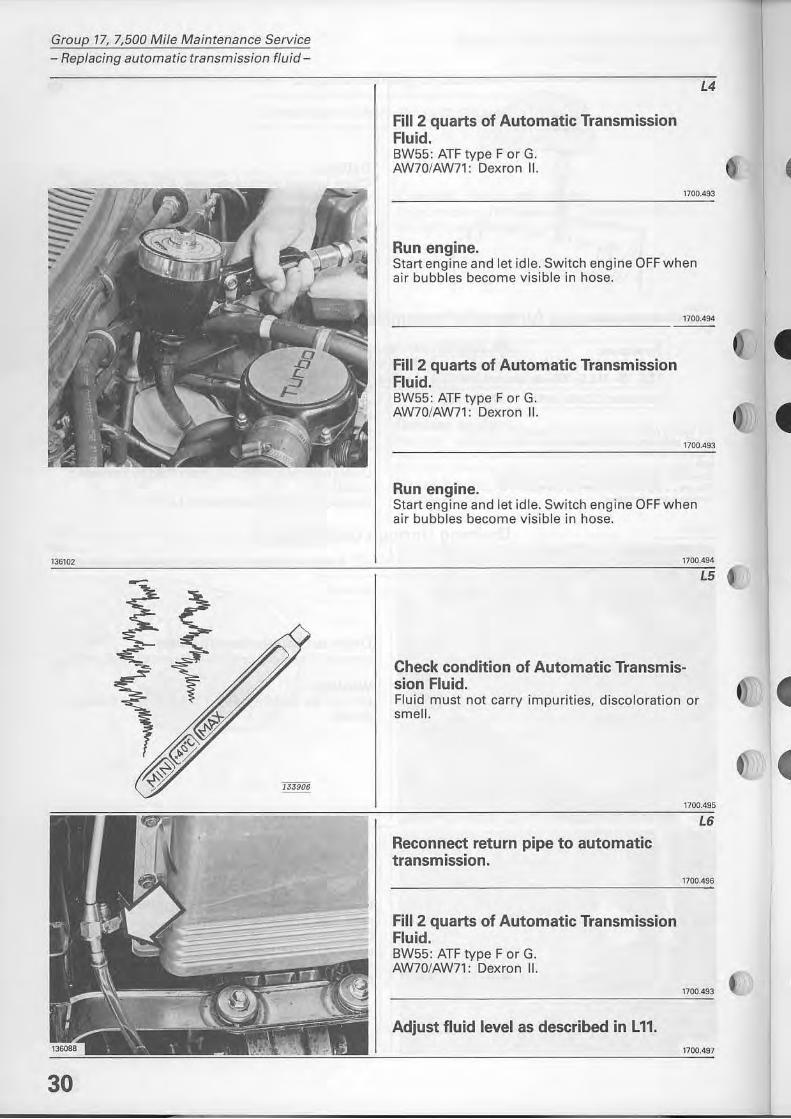
FiII 2 quarts of Automatic Transmission Fluid. BW55: ATF type F or G. AW70/AW71: Dexron II.
Run engine.
L4
1700.493
Start engine and let idle. Switch eng ine OFF when air bubbles become visible in hose.
FiII 2 quarts of Automatic Transmission Fluid. BW55: ATF type F or G. AW70/AW71: Dexron II.
Run engine.
1700.494
1700,493
Start engine and let idle. Switch engine OFF when air bubbles become visible in hose.
1700.494
L5
Check condition of Automatic Transmission Fluid. Fluid must not carry impurities, discoloration or smell.
Reconnect return pipe to automatic transmission.
Fill 2 quarts of Automatic Transmission Fluid. BW55: ATF type F or G. AW70/AW71: Dexron II.
Adjust fluid level as described in Lll.
1700.495
L6
1700,496
1700.493
1700.497
Group 17, 7,500 Mile Maintenance Service Replacing automatic transmission fluid
----------- Removing oil pan ------------_
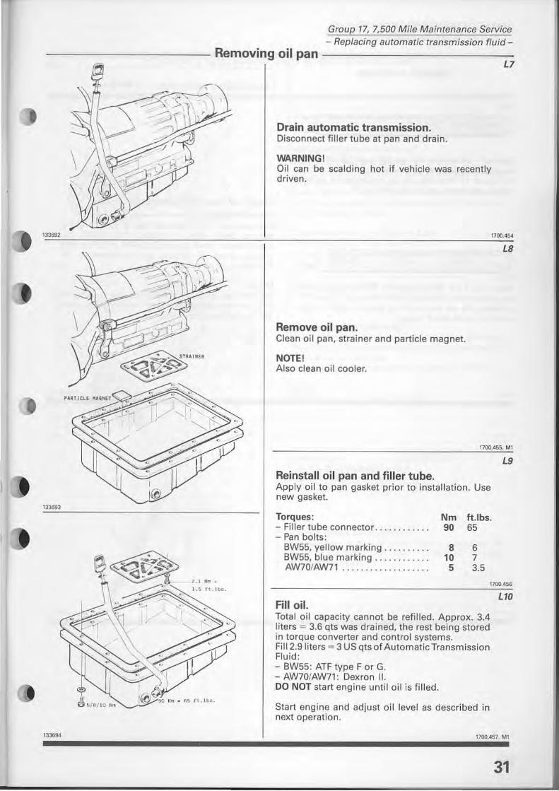
, Drain automatic transmission. Disconnect filler tube at pan and drain.
WARNING! Oil can be scalding hot if vehicle was recently driven.
L7
133692 1100.454
"
I (CJ
13J6Sl
"",.
L8
Remove oil pan. Clean oB pan, strainer and particle magnet.
NOTE! Alsa clean oil cooler.
1700.455. MI
Reinstall oil pan and filler tube, Apply oi! to pan gasket prior to installation. Use new gasket.
Torques: Nm tUbs, - Filler tube connector. . .. . ..... . 90 65 - Pan bolts:
BW55, yeJlow marking ......... . 8 6 BW55, blue marking ........... . 10 7 AW70/AW71 """",,"""'" 5 3,5
L9
1700.456
FiII oil. Total oil capacity cannot be retilled. Approx. 3.4 liters = 3.6 qts was drained, the rest being stored in torque converter and controi systems. Fill 2.9 liters "" 3 US qts of Automatie Transmission Fluid: - BW55: ATF type F or G. - AW70/AW71: Dexron II. DO NOT start engine until oil is filled.
Start engine and adjust oil level as deseribed in next operation.
LID
1100.457. MI
31
Group 17, 7,500 Mile Maintenance Service Checking automatic transmission fluid-
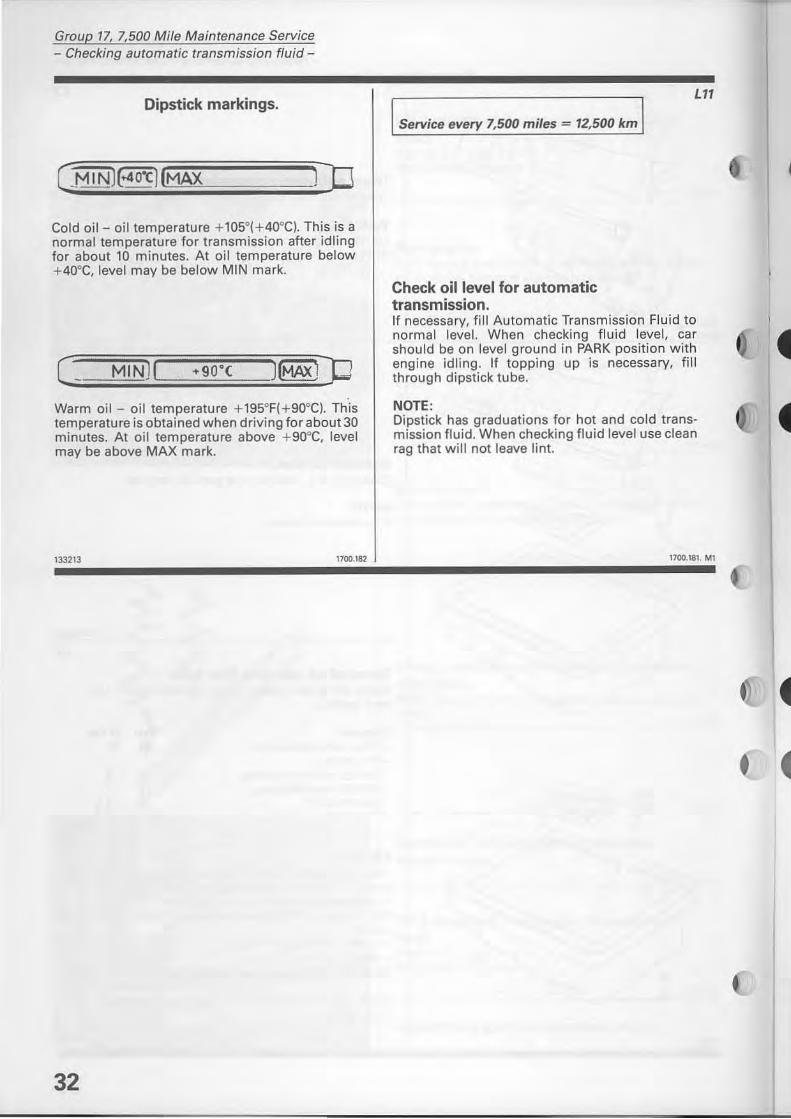
Dipstick markings.
Cold oil- oil temperature + 105°(+40°Cl. This is a normal temperature for transmission after idling for about 10 minutes. At oil temperature below + 40°C, level may be below MIN mark.
MINH
Warm oi! - oH temperature +195°F( +90°C). This temperature is obtained when driving for about 30 minutes. At oH temperature above +90°C, level may be above MAX mark.
133213 1700.182
32
Service every 7,500 miles = 12,500 km
Check oillevel for automatic transmission.
LI1
If necessary, fill Automatic Transmission Fluid to normalleveI. When checking fluid level, ear should be on level ground in PARK position with engine idling. If topping up is necessary, fill through dipstick tu be.
NOTE, Dipstick has graduations for hot and cold transmission fluid. When checking fluid level use dean rag that will not leave lint.
1700.181. MI
I
4
129562
Group 17, 7,500 Mi/e Maintenance Service
- 827 and 823-
Following operations refer to B21 and B23 (all)
I Service every 7,500 miles = 12,500 km J MI
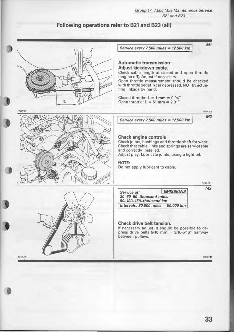
Automatic transmission: Adjust kickdown cable. Check cable length at closed and open throttle (engine off). Adjust if necessary. Open throttle measurement should be checked with throttle pedal in ear depressed, NOT by actuating linkage by hand.
Closed throttle: L = 1 mm = 0.04" Open throttle: L = 51 mm = 2.01"
I Service every 7,500 miles = 12,500 km I
Check engine controls
.,
Check joints, bushings and throttle shaft for wear. Check that cable, links and springs are serviceable and correctly installed. Adjust play. Lubricate joints, using a light oil.
NOTE, 00 not apply lubricant to cable.
Service at: EMISSIONS 30-60-90-thousand miles 50-100-150-thousand km I"terva/s: 30,000 miles = 50,000 km
Check drive belt tension.
1700.271
M3
If necessary adjust. It should be possible to depress drive belts 5-10 mm = 3/16-5/16" halfway between pulleys.
1700.241
33
Group 17, 7,500 Mi/e Maintenance Service - 821 and 823: adjust va/ves-
_________ B21 and B23 adjust valves ________ _ NI
12077?
" ....
120778
1186fi9
34
Service at: 30-60-90-thousand
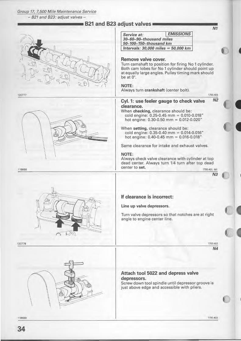
Remove valve cover. Turn camshaft to position for firing No 1 cylinder. 80th cam lobes for No 1 cylinder should point up at equally large angles. Pulley timing mark should be at 0°.
NOTE: Always tum crankshaft (center balt).
eyl. 1: use feeler gauge to check valve clearance. When checking, clearance should be:
cold engine: 0.25-0.45 mm = 0.010-0.01S" hot engine: 0.30-0.50 mm = 0.012-0.020"
When setting, clearance should be: cold engine: 0.35-0.40 mm = 0.014-0.016" hot engine: 0.40-0.45 mm = 0.016-0.01S"
1700,400
N2
Same clearance for intake and exhaust valves.
NOTE: Always check valve clearance with cylinder at top dead center. Always turn 1/4 turn after top dead center to set.
1700.401. MI
N3
If clearance is incorrect:
Line up valve depressors.
Tum valve depressors so that notches are at right angle to engine center line.
Attach tool 5022 and depress valve depressors.
1100,402
N4
Screw down tool spindle until depressor groove is just above edge and accessible with pliers.
1700.403
• •
118870
118671
119745
120779
5026
4 00
Group 17, 7,500 Mi/e Maintenance Service 821 and 823: adjust vafves-
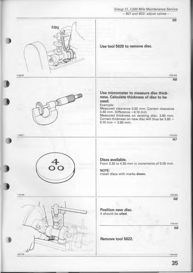
Use tool 5026 to remove disc.
Use micrometer to measure disc thickness. Calculate thickness of disc to be used. Example:
N5
1700.404
N6
Measured clearance 0.50 mm. Correct clearance 0.40 mm. Difference + 0.10 mm. Measured thickness on existing disc: 3.80 mm. Correct thickness on new disc will thus be 3.80 + 0.10 mm = 3.90 mm.
1700.405
N7
Discs available. From 3.30 to 4.50 mm in increments of 0.05 mm.
NOTE, Install discs with marks down.
Position new disc. It shou ld be oiled.
Remove tool 5022.
1700.406
NB
1100 . .07
N9
1100._
35
Group 17, 7,500 Mi/e Maintenance Service - 821 and 823: adjusr va/ves-
120780
12078 1
\
118668
36
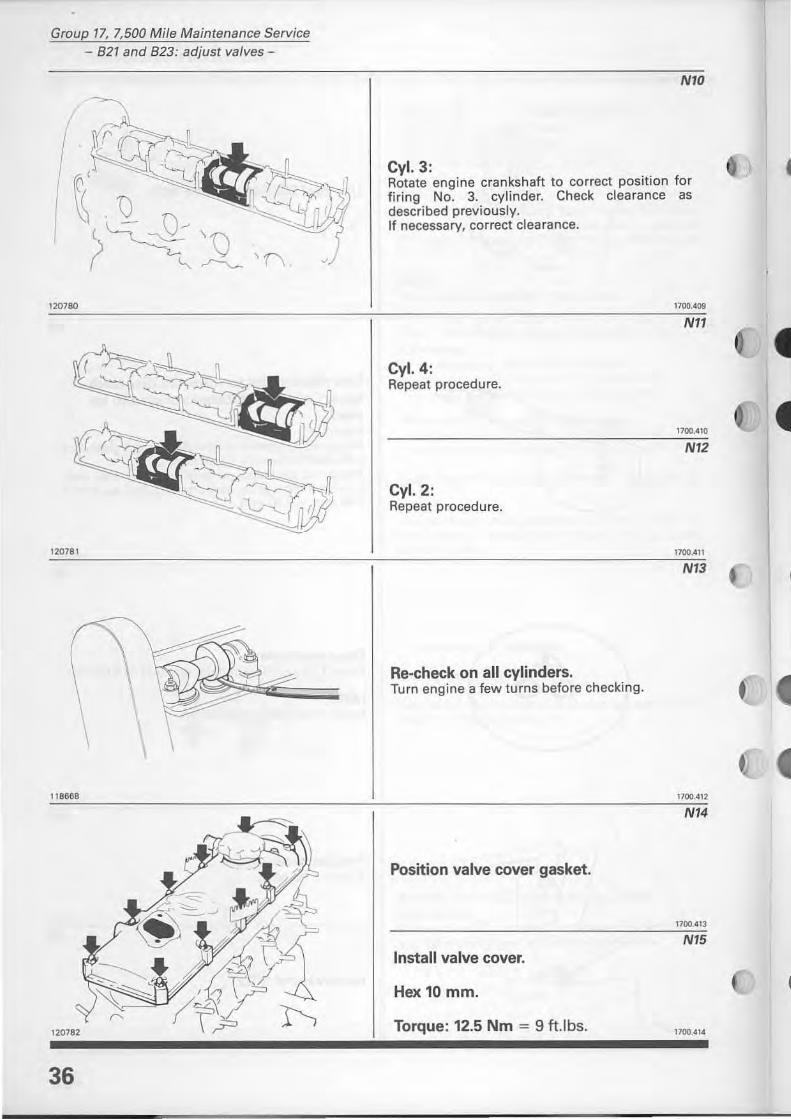
NIO
ey!. 3: Rotate engine crankshaft to correct position for firing No. 3. cylinder. Check clearance as described previously. If necessary, correct clearance.
1100.409
Nl1
eyl. 4: Repeat procedure.
1100.410
NI2
eyl.2: Repeat procedure.
1700.4n
NI3
Re-check on all cylinders. Turn engine a few turns before checking .
1100.412
NI4
Position valve cover gasket.
1700,' 13
NI5 lostall valve cover.
Hex 10 mm.
Torque: 12.5 Nm = 9 tt.lbs. 1700.414
•
Group 17, 7,500 Mile Maintenance Service - 821 and 823: replace timing gear belt-
-------821 and 823: replacetiming gear belt 01
124187
124188
~ \
124189
124 190
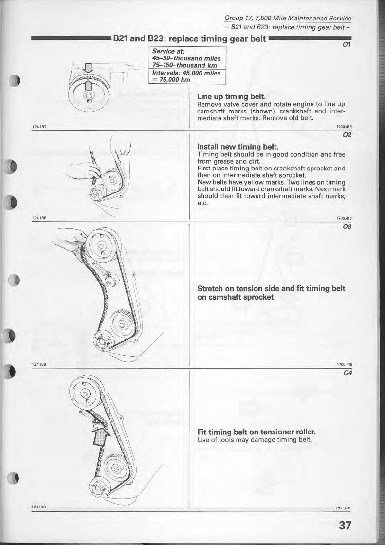
Service at: 45-90-thousand miles
Line up timing belt. Remove valve cover and rotate engine to line up camshaft marks (shown), crankshaft and intermediate shaft marks. Remove old belt.
1700_416
02
Install new timing belt. Timing belt should be in good condition and free from grease and dirt. First place timing belt on crankshaft sprocket and then on intermediate shaft sprocket. New belts have yellow marks. Two lines on timing belt should fittoward crankshaft marks. Next mark should then fit toward intermediate shaft marks, etc.
1700.417
03
Stretch on tension side and fit timing belt on camshaft sprocket.
Fit timing belt on tensioner roller. Use of tools may damage timing belt.
1700_418
04
1700.419
37
Group 77, 7,500 Mi/e Maintenance Service - 827 and 823: replace timing gear belt-
124191
124192
124193
38
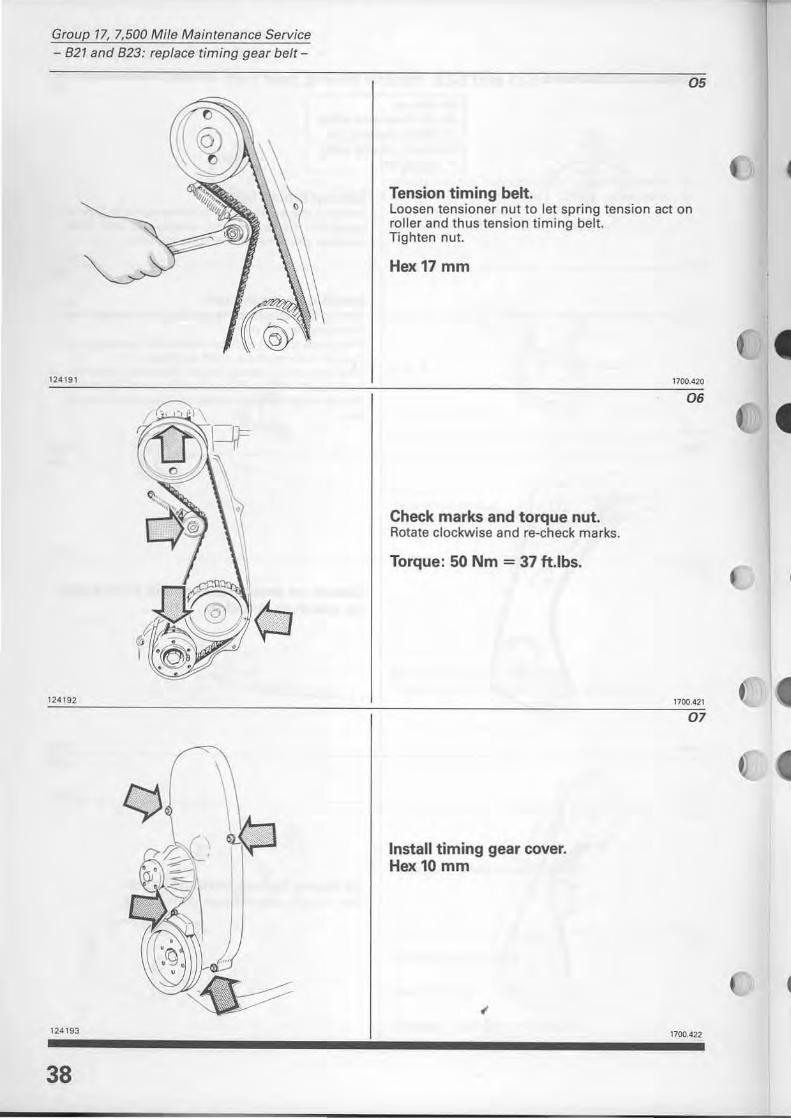
05
Tension timing belt. loosen tensioner nut to let spring tension act on roller and thus tension timing bell. Tighten nul.
Hex17 mm
Check marks and torque nut. Rotate clockwise and re-check marks.
Torque: 50 Nm = 37 tt.lbs.
Install timing gear cover. Hex 10 mm
1100.410
06
1700.421
07
1100.422
•
=
133700
133316
129569
Group 17, 7,500 Mi/e Maintenance Service - 821A-
B21A1Canada
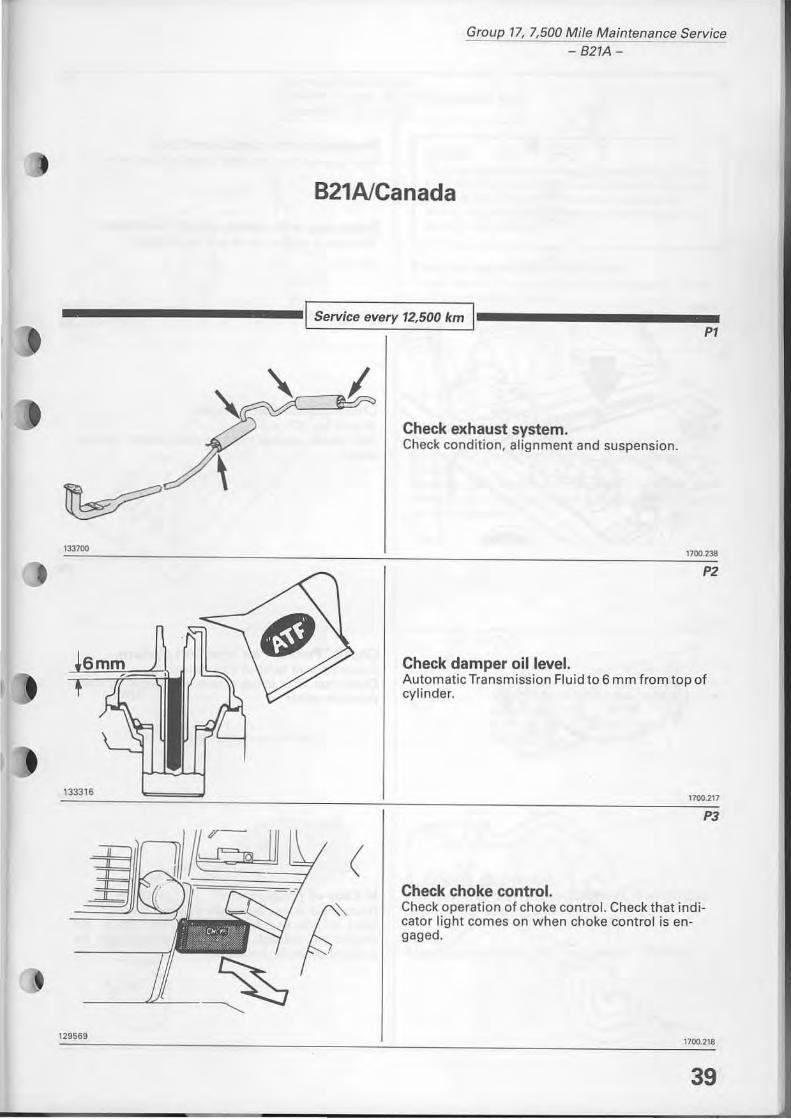
I Service every 12,500 km P1
(
Check exhaust system. Check condition, aHgnment and suspension.
1700.238
P2
Check damper oillevel. Automatic Transmission Fluid to 6 mm from top of cylinder.
1100.217
Check choke control. Check operation of choke controI. Check that indicator light comes on when choke contral is engaged.
1700.218
39
Group 77. 7,500 Mi/e Maintenance Service - 821A-
130695
•
127165
40
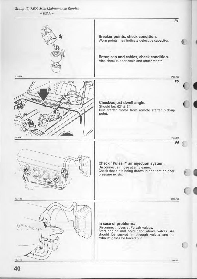
P4
Breaker points, check condition. Worn points may indicate defective capacitor.
Rotor, cap and cables, check condition. Also check rubber seals and attachments
1100. 245
CheckJadjust dwell angle. Should be: 62° ± 3°. Run starter motor from remote starter pick-up point.
P5
1700.219
Check "Pulsair" air injection system. Disconnect air hose at air cleaner. Check that air is being drawn in and that no back pressure exists.
P6
1700.254
In case of problems: Disconnect hoses at Pulsair valves. Start engine and hold hand above valves. Air should be sucked in through va lves and no exhaust gases be forced out.
1700.255
f
•
127523
",.n
Group 77, 7,500 Mi/e Maintenance Service - B21A
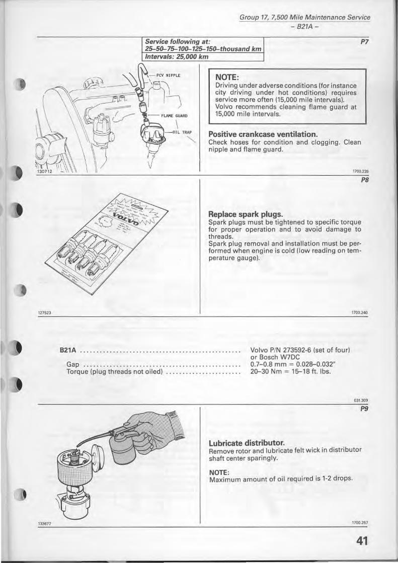
Service following at: P7 2>5{}...7> 10{}...12> 15{}...thousand km Intervals: 25,000 km
NOTE: Driving under adverse conditions (for instance city driving under hot conditions) requires service more ohen (15,000 mile intervals). Volvo recommends cleaning fia me guard at 15.000 mile intervals.
Positive crankcase ventilation. Check hoses for condition and clogging. Clean nipple and flame guard.
1700.239
Replace spark plugs. Spark plugs must be tightened to specific torque for proper operation and to avoid damage to threads. Spark plug removal and installation must be performed when engine is cold (low reading on temperature gauge).
PS
1700.240
821A ................................. • .. .. .. • ........
Gap ............... ....... .......... • . . ..• .•. ....... Torque (plug threads not oiled) .....• . •... . . . • .... ... .
Volvo PIN 273592-6 (set of four) or Bosch W70C 0.7-0.8 mm = 0.028-0.032" 20-30 Nm = 15-18 h. Ibs.
Lubricate distributor.
031.309
P9
Remove rotor and lubricate felt wick in distributor shah center sparingly.
NOTE: Maximum amount of oil required is 1-2 drops.
1700.257
41 /
Group 17, 7,500 Mile Maintenance Service - B2IA-
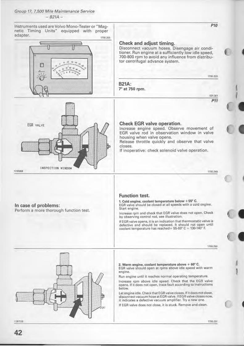
Instruments used are Volvo Mono-Tester or "Magnetit Timing Units" equipped with proper adapter.
EGR VALVE
129~6e
.. ... ..... lO
• • • 10 .. ... .. >O ,.~ ....
. ~ • • '·,i",,-, "
In case of problems:
•
Perform a more thorough function test.
128708
42
1100.205
PIO
Check and adjust timing. Disconnect vacuum hoses. Disengage air conditioner. Run engine at a sufficiently low idle speed, 700-800 rpm to avoid any influence from distributor centrifugal advance system .
17oo_2ZO
B21A: 70 at 750 rpm .
0]1.301
Pl1
Check EGR valve operation. Increase engine speed. Observe movement of EGR valve rod in observation window in valve housing when valve opens. Release throttle quickly and observe that valve closes. If inoperative: check solenoid valve operation.
1700.249
Function test. ,. Cold engine, coolant temperature below + 55° C. EGR velve should be closed at all speeds with a cold engine. Start engine. Increase rpm and check that EGR valve does not open. Check by observing controi rod, see illustralion. II EGR valve opens, il is an indicalion Ihallhermostatic valve is defective and should be replaced. It should not open until coolant temperature has reached+ 55_60° C '" 130·140· F.
1100.250
2. Warm engine, coolant temperature above + 60° C. EGR valve should open at rpms above idle speed with warm engine. Run engine until it feaches normaloperating temperature.
Increase rpm above id le speed. Check that the EGR valve opens. lf it does not open, trace lault according to instructions below.
Let engine id le. Check that EGR valve closes.lfi! does not close, disconnect vacuum hose at EGR valve.lf EGR valve closes now, it indicates a defeclive vacuum amplifier. Try a new one.
If EGR valve does not close, it is stuck. Remove and clean.
1700.251
\ I
•
, I
i r
I~
128399
D ) ,
128521
129566
~
l~
l l "1
1307()7
Group 17, 7,500 Mile Maintenance Service
821A
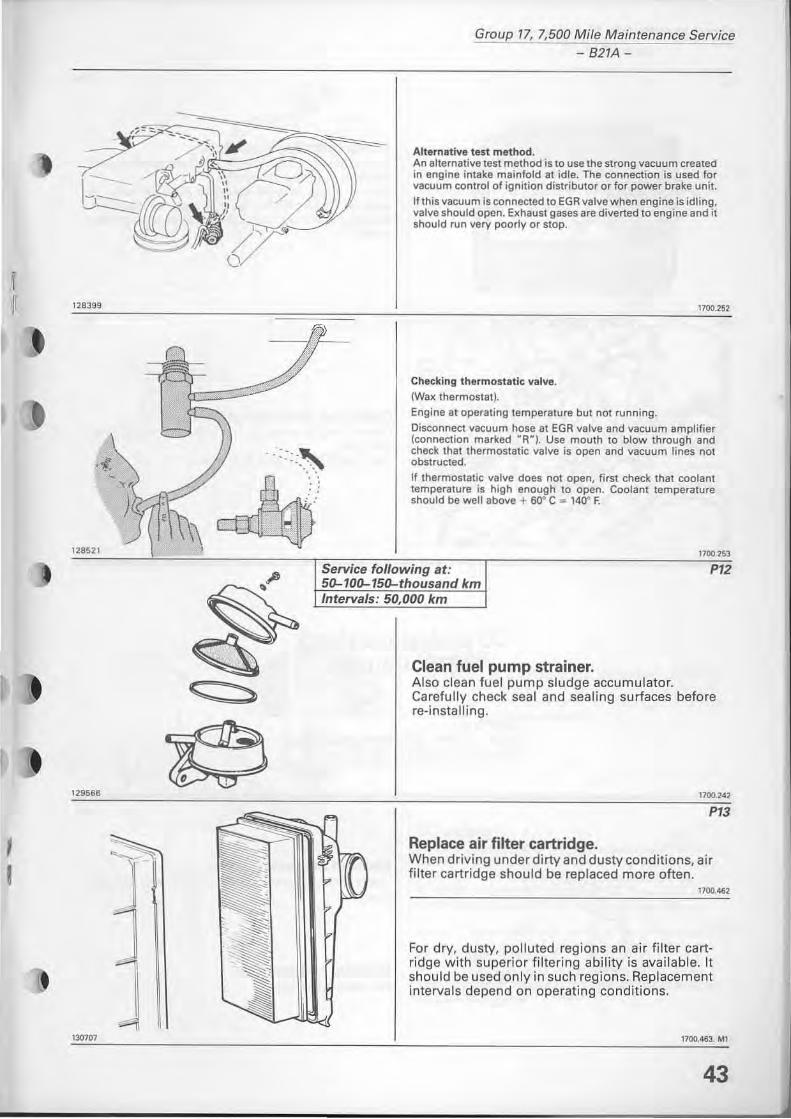
Alternative test method. An alternative test method is to use the strong vacuum t realed in engine intake mainfold at idle. The connection is used for vacuum contral of ignition distribulor or for power brake unit.
If this VBcuum is connected to EGR valve when engine is idling, valve should open. Exhaust gases are diverted to engine and il should run very poorly or stop.
Checking thermostatic valve. (Wax thermostat).
Engine at oper8ting temperature bu! nOl running.
1700.252
Disconnect vacuum hose at EGR valve and vacuum ampli fier (connection marked -R-I. Use mouth to blow through and check thaI thermostatic vatve is open and vacuum lines not obstructed.
If thermostatic valve does not open, first check that coolant temperature is high enough lo open. Coolan! temperature should be weil above + 60· C _ 140" F.
Service following at: 50-100-150-thousand km Intervals: 50,000 km
Clean fuel pump strainer.
1700.2&3
P12
Also clean fuel pump sludge accumulator. Carefully check sea I and sealing surfaces before re-installing .
17\l().242
P13
Replace air fitter cartridge, When driving under dirty and dusty conditions, air filter cartridge should be replaced more often.
1700.462
For dry, dusty, polluted regions an air f ilter cartridge with superior filtering ability is available. It should be used only in such regions. Replacement intervals depend on operating conditions.
1700.463. MI
43
Group 17, 7,500 Mi/e Maintenance Service - 821A-
118$19
44
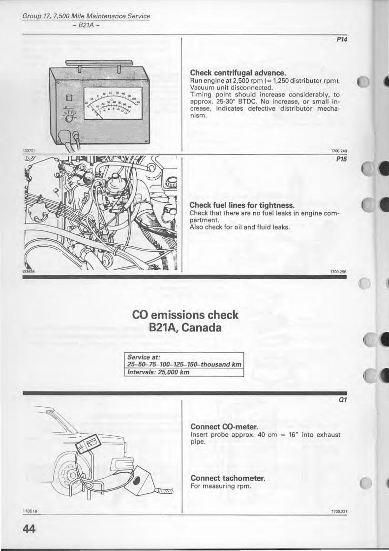
P14
Check centrifugal advance. Aun engine at 2,500 rpm (= 1,250 distributor rpm). Vacuum unit disconnected. Timing point should increase conside rably, to approx. 25-300 BTDC. No increase, or small increase, indicates defective distributor mechanism.
1700.248
P15
Check fuellines for tightness. Check that there are no fuelleaks in engine compartment. Also check for oil and fluid leaks.
CD emissions check B21A, Canada
Service at: 25-50-75-100-125-150-thousand km Intervals: 25,000 km
Connect CO-meter.
al
Insert probe approx. 40 cm = 16H into exhaust pipe.
Connect tachometer. For measuring rpm.
1700.22\
130696
•
133545
Group 17, 7,500 Mile Maintenance Service - 827A ca check-
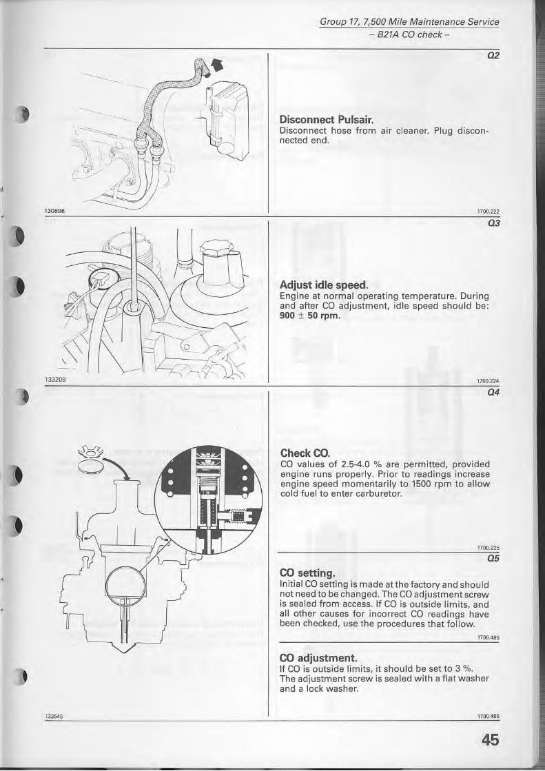
02
Disconnect Pulsair. Disconnect hose from air cleaner. Plug disconnected end.
1700.222
03
Adjust idle speed. Engine at normaloperating temperature. During and after CD adjustment, idle speed should be: 900 ± 50 rpm.
1700.224
04
CheckCO. ca values of 2.5-4.0 % are permitted, provided engine runs properly. Prior to readings increase engine speed momentarily to 1500 rpm to allow cold fuel to enter ca rburetor.
1700,225
05
CO setting . Initial CD setting is made at the factory and should not need to be changed. The ca adjustment screw is sea led from access. If ca is outside limits, and all other causes for incorrect CD readings have been checked. use the procedures that follow.
1700.485
CO adjustment. If CD is outside limits. it should be set to 3 %. The adjustment screw is sealed with a flat washer and a lock washer.
1700.486
45
Group 17, 7,500 Mife Maintenance Service 821A CO check -
"'~
133~7
•
1335<18
"'''' 46
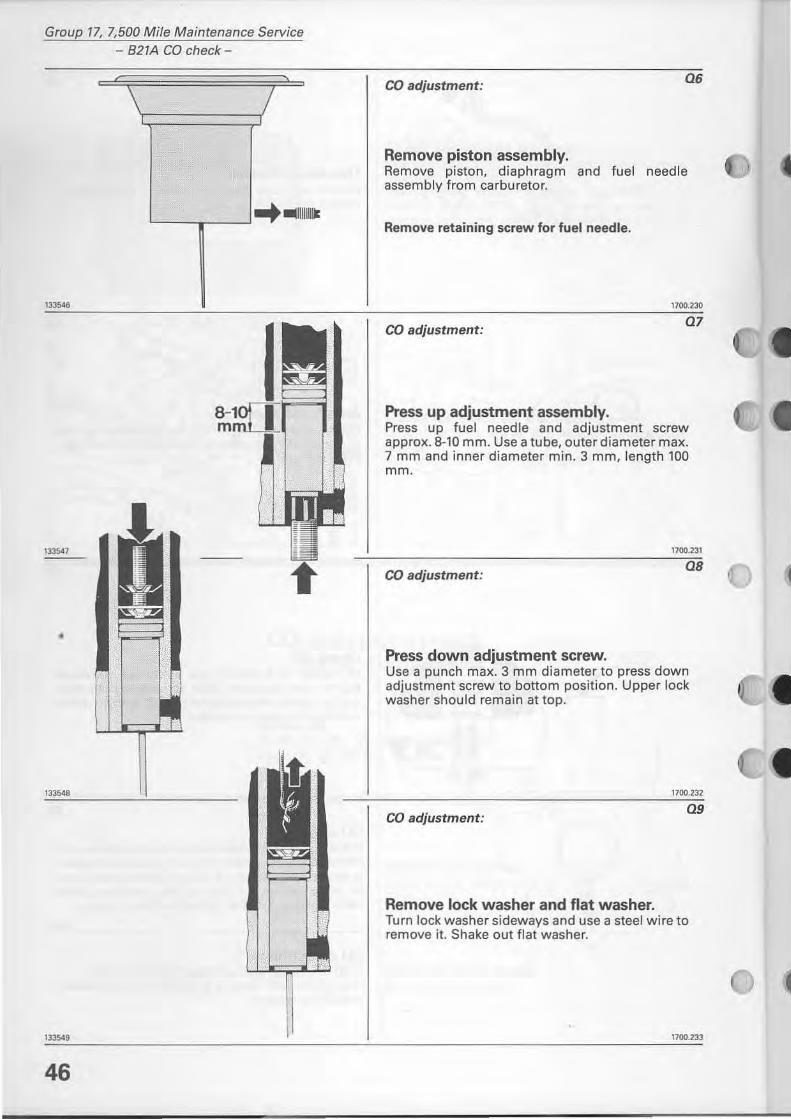
CD adjustment: 06
Remove piston assembly. Remove piston, diaphragm assembly from carburetor.
and fuel needle
Remove retaining screw for fuel needle.
1700.230
CD adjustment: 07
Press up adjustment assembly. Press up fuel needle and adjustment screw approx. 8-10 mm. Use atube, outer diameter max. 7 mm and inner diameter min. 3 mm, length 100 mm.
1700.231
CD adjustment: os
Press down adjustment screw. Use a punch max. 3 mm diameter to press down adjustment screw to bottom position. Upper lock washer should remain at top.
1700.232
CD adjustment: 09
Remove lock washer and flat washer. Turn lock washer sideways and use a steel wire to rem ove it. Shake out flat washer.
1700.233
5159
ni
133550
,. .. :- TOOL 5159
r: .. WGS
n .o. t (
133202
rlf 5159
.r ~ l ,--, =!!~fd U~ ~
1332il
Group 17, 7,500 Mi/e Maintenance Service - 821A ca check-
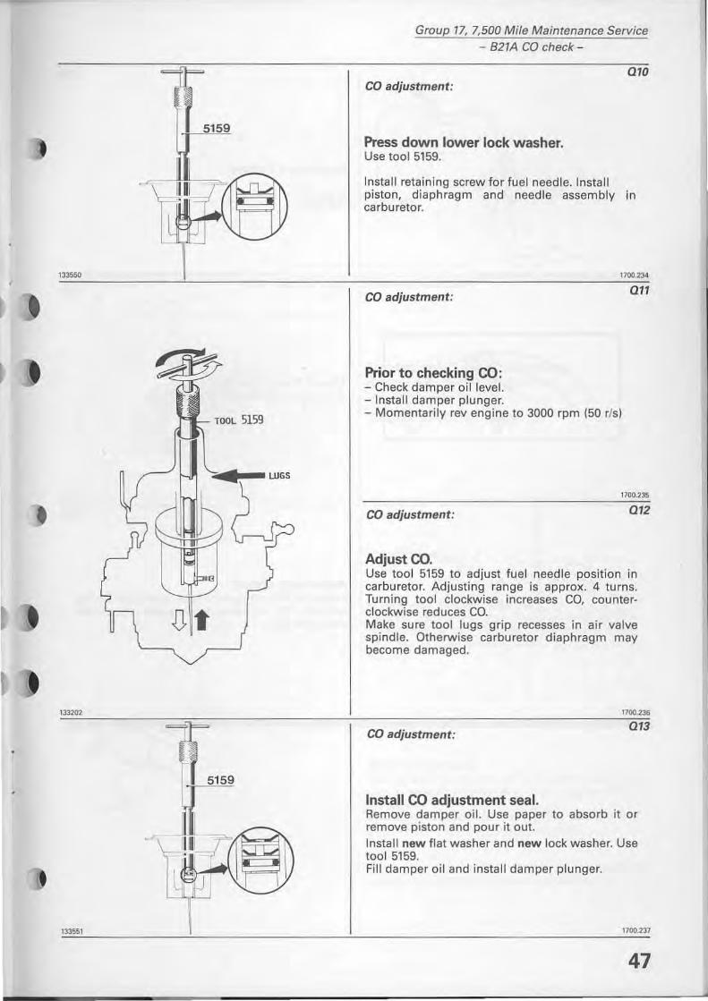
CD adjustment:
Press down lower lock washer. Use too I 5159.
010
Install retaining screw for fuel needle. Install piston, diaphragm and needle assembly in carburetor.
CD adjustment:
Prior to checking 00: - Check damper oi! level. - Install damper plunger.
1700.234
011
- Momentarily rev engine to 3000 rpm (50 rIs)
1700.235
CD adjustment: 012
Adjustoo. Use tool 5159 to adjust tuel needle position in carburetor. Adjusting range is approx. 4 turns. Turning tool clockwise increases CO, counterclockwise reduces CO. Make sure tool lugs grip recesses in air valve spindie. Otherwise carburetor diaphragm may become damaged.
1700.236
CD adjustment: 013
Install 00 adjustment seal. Remove damper oi!. Use paper to absorb it or remove piston and pour it out. Install new flat washer and new lock washer. Use too15159. Fill damper oil and install damper plunger.
1700.237
47
Group 17, 7,500 Mi/e Maintenance Service - 821A CD check-
"
130692
130693
48
014
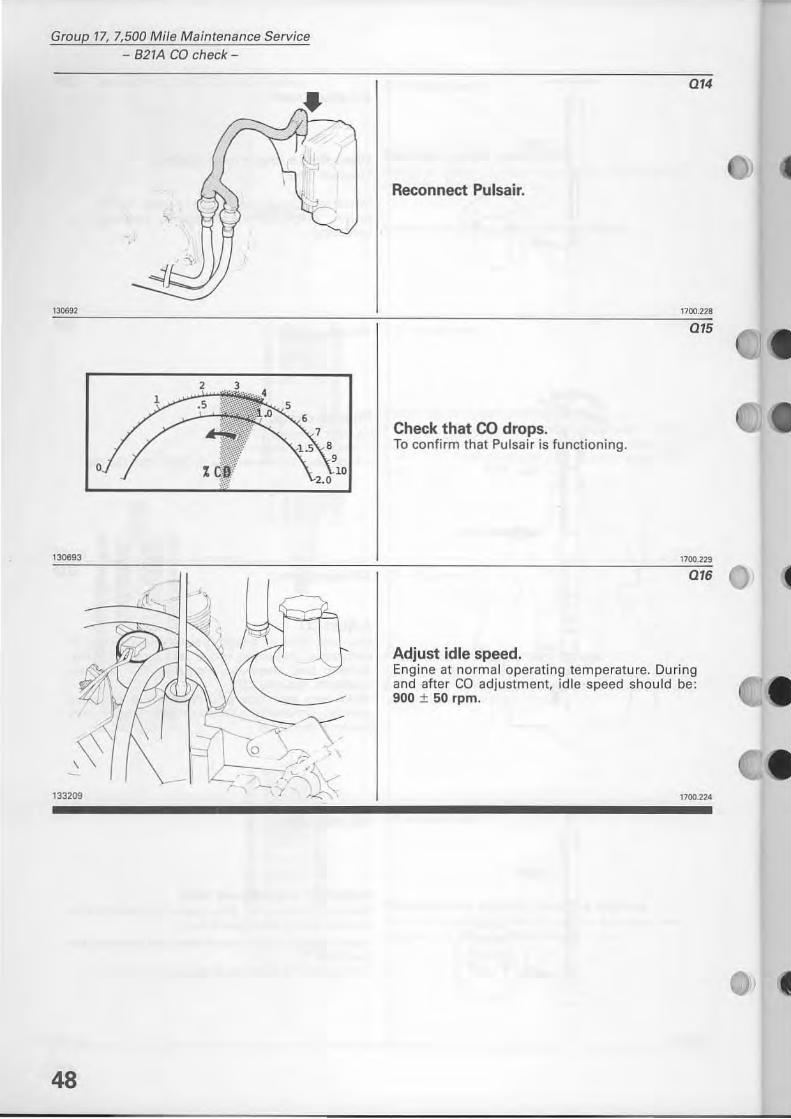
Reconnect Pulsair.
1700.228
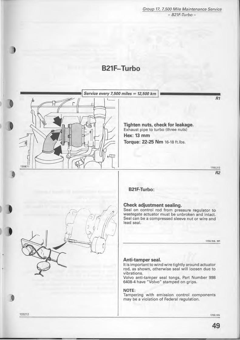
015
Check that CO drops, To confirm that Pulsa ir is functioning.
1700.229
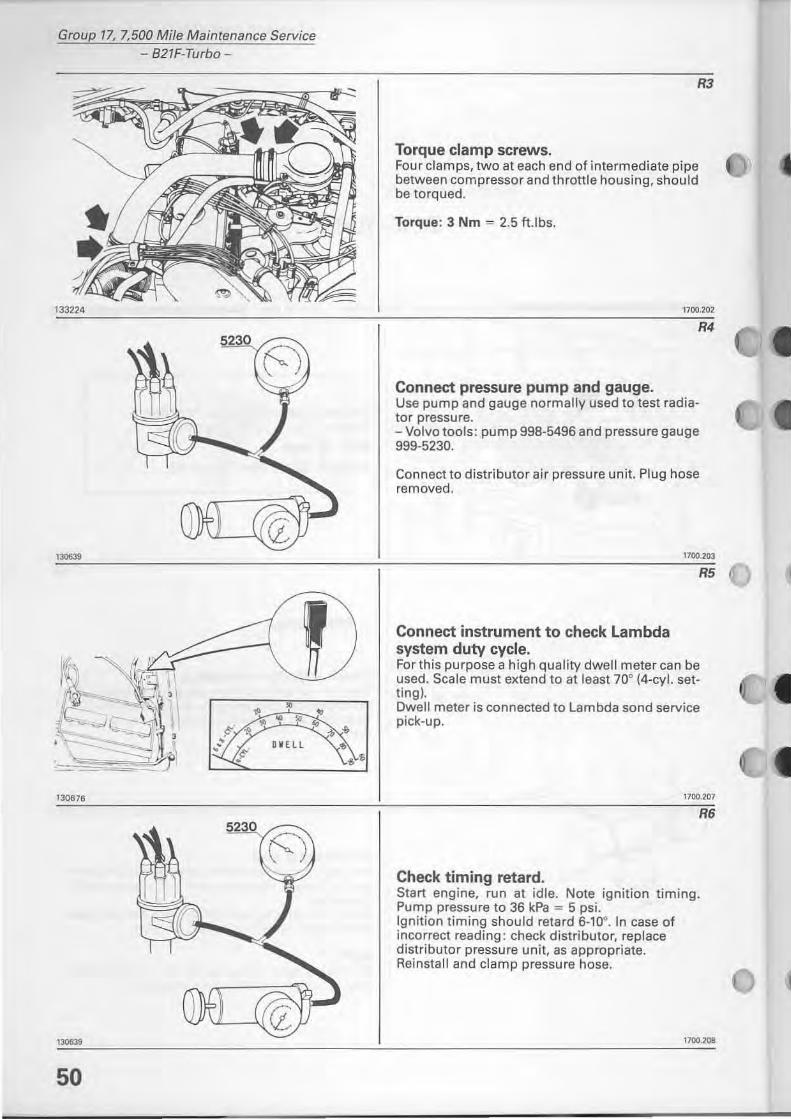
016
Adjust idle speed, Engine at normaloperating temperature. During and after ca adjustment, id le speed should be: 900 ± 50 rpm.
1700.224
II
II
133212
Group 77. 7,500 Mi/e Maintenance Service - 821F-Turbo-
B21F-Turbo
.\ Service every 7,500 miles = 12,500 km I-----------~
~~~~~~:J~==~~~~':: Rl
~) 5 j rr{'l!;: J, 'J
,
o
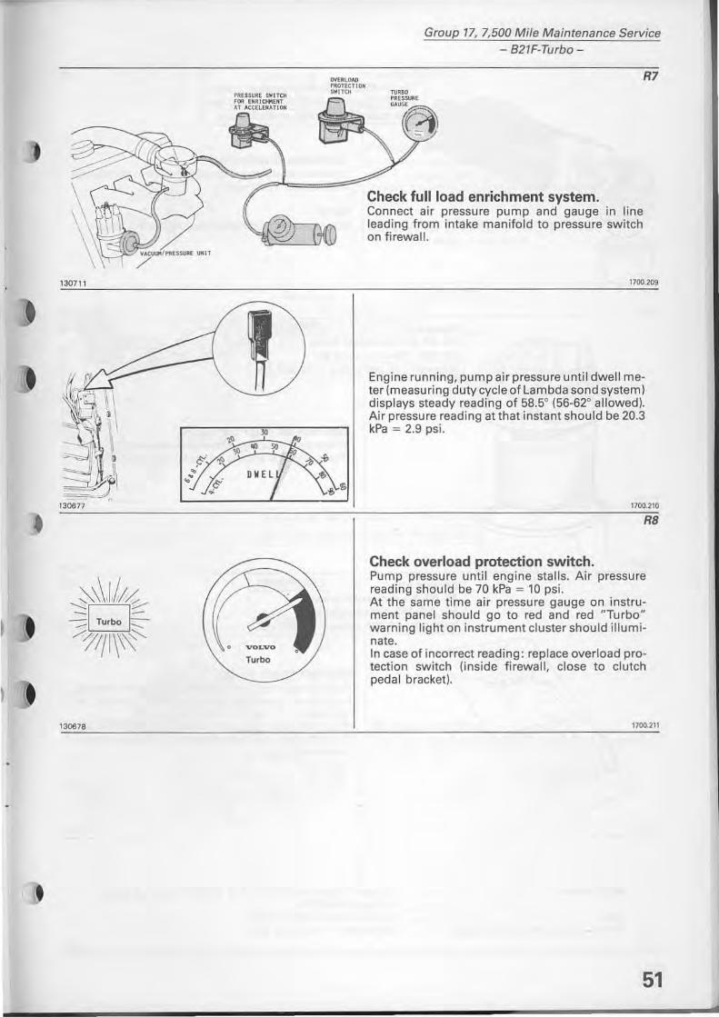
Tighten nuts, check for leakage. Exhaust pipe to turbo (th ree nuts)
Hex: 13 mm Torque: 22-25 Nm 16-18 ft.lbs.
B21F-Turbo:
Check adjustment sealing. SeaJ on controi rod from pressure regulator to wastegate actuator must be unbroken and intact. Sea I can be a compressed sleeve nut or wire and lead seal.
1100.1001, M1
Anti-tamper seal. Il is important to wind wire tightlyaround actuator rad, as shown, otherwise seal will loosen due to vibrations. Volvo anti-tamper seal long s, Part Number 998 6408-4 have "Volvo" stamped on grips.
NOTE, Tampering with emission contra I components may be a violation of Federal regulation.
1100.105
49
Group 17, 7,500 Mile Maintenance Service - 821F-Turbo-
,,""
• ~ • • • • • DVEll
130676
2 O
, .... 50
•• • . '
R3
Torque clamp screws. Four clamps, two at each end of intermediate pipe between compressor and throttle housing, should be torqued.
Torque: 3 Nm = 2.5 ft.lbs.
1700.202
R4
Connect pressure pump and gauge. Use pump and gauge normally used to test radiator pressure. - Volvo toois: pump 998-5496 and pressure gauge 999·5230.
Connect to distributor air pressure unit. Plug hose removed.
Connect instrument to check Lambda system duty eyele.
1700.21l3
R5
Forthis purpose a high quaiity dwell meter can be used. Scale must extend to at least 70° (4-cyl. setting). Dwell meter is connected to Lambda sond service pick-up .
1700,207
Check timing retard. Start engine, run at idle. Nate ignition timing. Pump pressure to 36 kPa = 5 psi. Ignition timing should retard 6_10°. In case of incorrect reading : check distributor. replace distributor pressure unit, as appropriate. Reinstall and clamp pressure hose.
R6
1700.208
130711
I 130678
Group 17, 7,500 Mile Maintenance Service - B21F-Turbo-
Check fullload enrichment system. Connect air pressure pump and gauge in line leading from intake manifold to pressure switch on firewall.
R7
1'00.209
Engine running, pump air pressure until dwell meter (measuring duty cycle of Lambda sond system) displays steady reading of 58.50 (56-62° allowed). Air pressure reading at that instant should be 20.3 kPa = 2.9 psi.
1700.210
R8
Check overload protection switch. Pump pressure until engine stalls . Air pressure reading should be 70 kPa "" 10 psi. At the same time air pressure gauge on instrument panel should go to red and red "Turbo" warning light on instrument cluster should illuminate. In case of inco rrect reading: replace overload protection switch (inside firewall, close to clutch pedal bracket).
1700.211
51
Group 17, 7,500 Mile Maintenance Service - 827F-Turbo -
130708
52
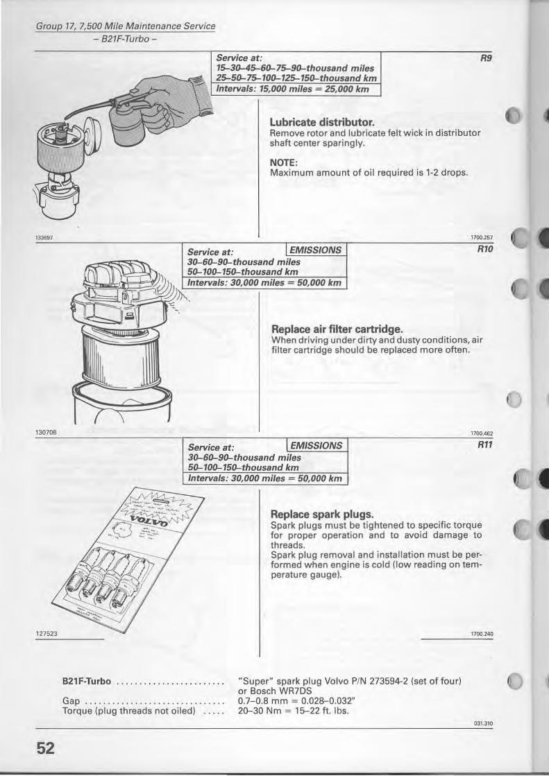
Lubricate distributor. Remove rotor and lubricate felt wick in distributor shaft center sparingly.
NOTE: Maximum amount of oH required is 1-2 drops.
Service at: 30-60-90-thousand
Replace air filter cartridge. When driving under dirty and dusty conditions, air filter cartridge should be replaced more often.
1100.462
Service at: EMISSIONS Rlf 30-60-90-thousand miles 50-100-150-thousand km Intervals: 30,000 miles = 50,000 km
B21F-Turbo ................... . ... .
Gap .............................. . Torque (plug threads not oiled)
Replace spark plugs. Spark plugs must be tightened to specific torque for proper operation and to avoid damage to threads. Spark plug rem oval and installation must be performed when engine is cold (low reading on temperature gauge).
"Super" spark plug Volvo P/N 273594-2 (set of four) or Bosch WR7DS 0.7-0.8 mm = 0.028-0.032" 20-30 Nm = 15--22 ft. Ibs.
1700.240
031.310
120995
1l37OJ
Group 17, 7,500 Mile Maintenance Service
- 821F-Turbo-
Service at: EMISSIONS 30-60-90-thousand miles 50-100-150-thousand km Intervals: 30,000 miles = 50,000 km
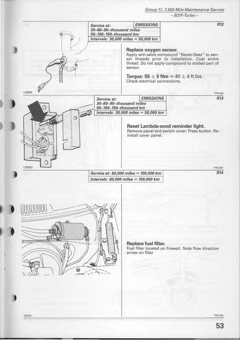
Replace oxygen sensor.
R12
Apply anti-seize compound " Never-Seez" to sensor threads prior to installation. Coat entire thread. 00 not apply compound to slotted part of sensor.
Torque: 55 ± 5 Nm = 40 ± 4 tUbs. Check electrical connections.
Reset Lambda-sond reminder light. Remove panel and switch cover. Press button. Reinstall cover panel.
Service at: 60,000 miles = 100,000 km
Interva/s: 60,000 miles = 100,000 km
Replace tuel filter.
1100.467
R14
Fuel filter located on firewall. Note flow direction arrow on filter
53 l
Group 17, 7,500 Mi/e Main tenance Service - 821F·Turbo -
to a i r c;: l oano r
124032
54
,.
Service at: 60,000 miles = 100,000 km Intervals : 60,000 miles = 100,000 km
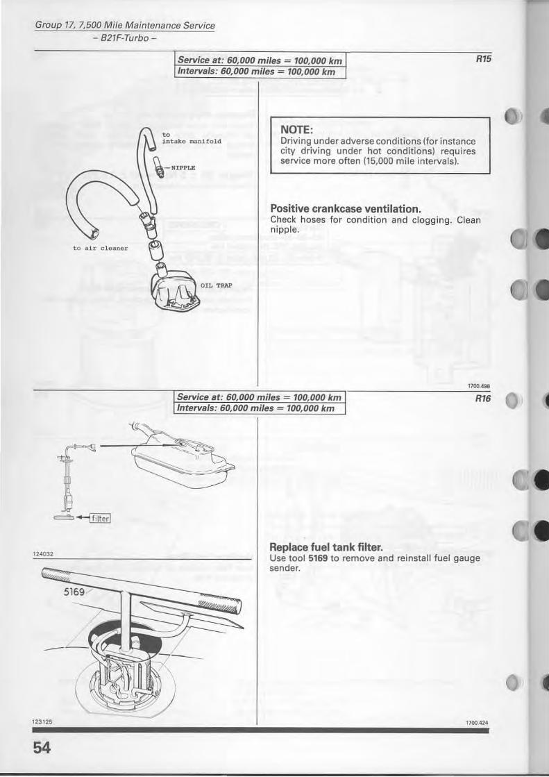
NOTE:
RI5
i nta ke aanifold Driving under adverse cond itions (for instance city driving under hot conditionsl requi res service more otten (15,000 mile intervalsl.
Positive crankease ventilation. Check hoses fo r condit ion and clogg ing. Clean nipple.
Service at: 60,000 miles = 100,000 km Intervals : 60,000 miles = 100,000 km
Replace luel tank filter.
1700.498
RI6
Use tool 5169 to rem ove and reinstall fuel gauge sender.
1700.424
,
130707
121513
Group 17, 7,500 Mile Maintenance Service
- 823F-
B23F
Service at: EMISSIONS 30-60-90-thousand miles 50-100-150-thousand km Interva/s: 30,000 miles = 50,000 km
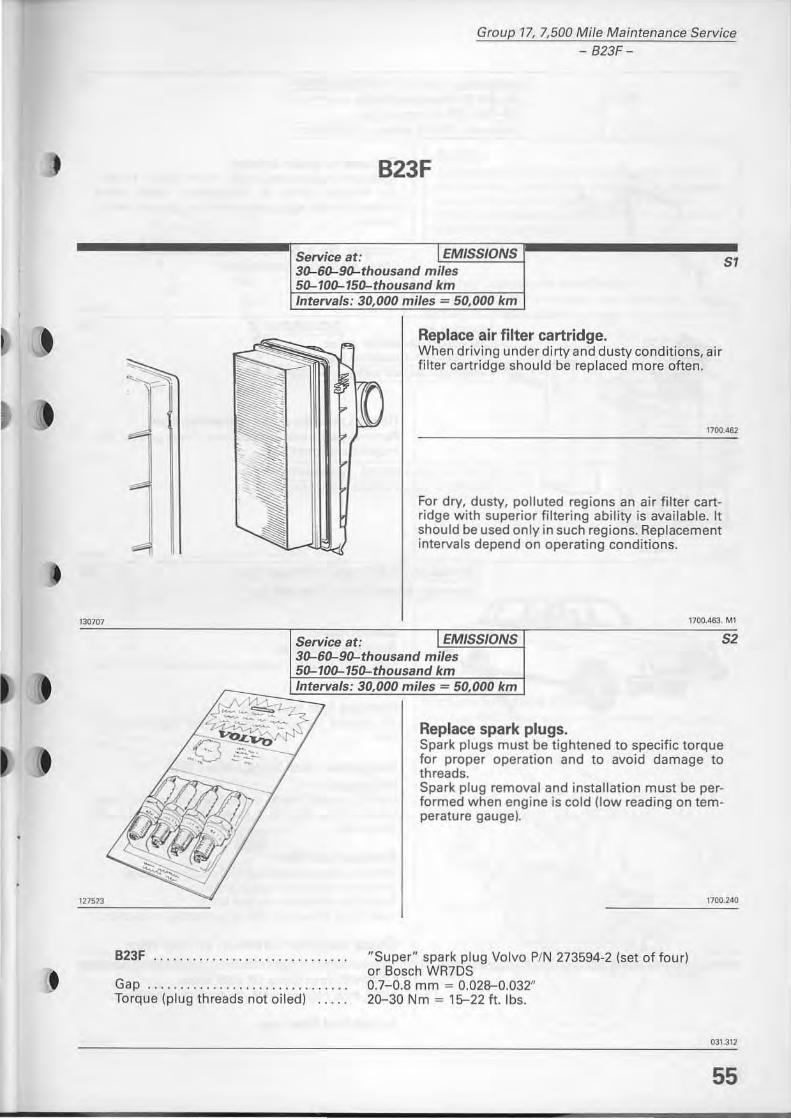
Replace air filter cartridge. When driving under dirty and dusty conditions, air filter cartridge should be replaced more eften.
SI
1700.462
For dry, dusty, polluted regions an air filter cart· ridg e with superior f iltering ability is available. It should be used on ly in such regions. Replacement intervals depend on operating conditions.
1700.463. MI
Service at: EMISSIONS S2 30-60-90-thousand miles 50-100-150-thousand km Intervals: 30,000 miles = 50,000 km
B23F """,,"""""""""""
Gap ................. . ...... . ... . Torque (plug threads not oiled) .... .
Replace spark plugs. Spark plugs must be tightened to specific torque for proper operation and to avoid damage to threads. Spark plug rem ova l and installation must be performed when engine is cord (fow reading on temperature gaugel.
"Super" spark plug Volvo P/N 273594-2 (set of four) or Bosch WR7DS 0.7-0.8 mm = 0.028-0.032" 20-30 Nm = 15-22 f t. Ibs.
1700.240
031.312
55
Group 17, 7,500 Mi/e Maintenance Service - B23F-
120995
1332ill
56
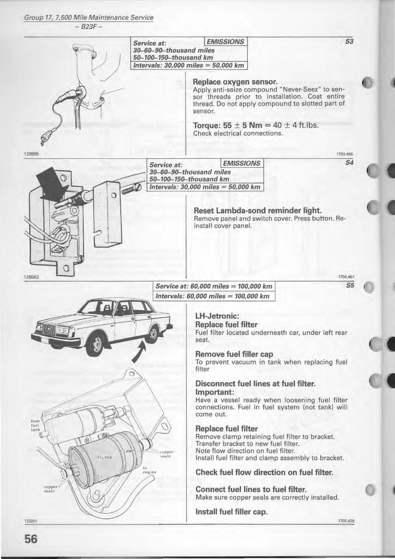
Service at: EMISSIONS S3 30-60-90-thousand miles 50-100-150-thousand km Intervals: 30,000 miles = 50.000 km
Replace oxygen sensor. Apply anti-seize compound "Never-Seez" to sensor threads prior to installation. Coat entire thread. Do not apply compound to slotted part of sensor.
Torque: 55 ± 5 Nm = 40 ± 4 tt.lbs. Check electrical connections.
1700.466
Service at: 30-60-90-thousand
Reset Lambda-sond reminder light. Remove panel and switch cover. Press button. Reinstall cover panel.
1700.467
Service at: 60,000 miles = 100,000 km
Intervals : 60,000 miles = 100,000 km
LH-Jetronic: Replace fuel filter
55
Fuel filter located underneath ear, under left rear seat.
Remove fuel filler cap To prevent vacuum in tank when replacing fuel filter
Disconnect fuellines at fuel filter. Important: Have avessel ready when laosening fuel filter connections. Fuel in fuel system (not tank) will come out.
Replace fuel filter Remove clamp retaining fuel filter to bracket. Transfer braeket to new fuel filter. Nate flow direction on fuel filter. Install fuel filter and clamp assembly to bracket.
Check fuel flow direction on fuel filter.
Connect fuel lines to fuel filter. Make sure copper seals are correctly installed.
Install fuel filler cap. 1700.421
124032
•
J
Group 17, 7,500 Mile Maintenance Service - 823F-
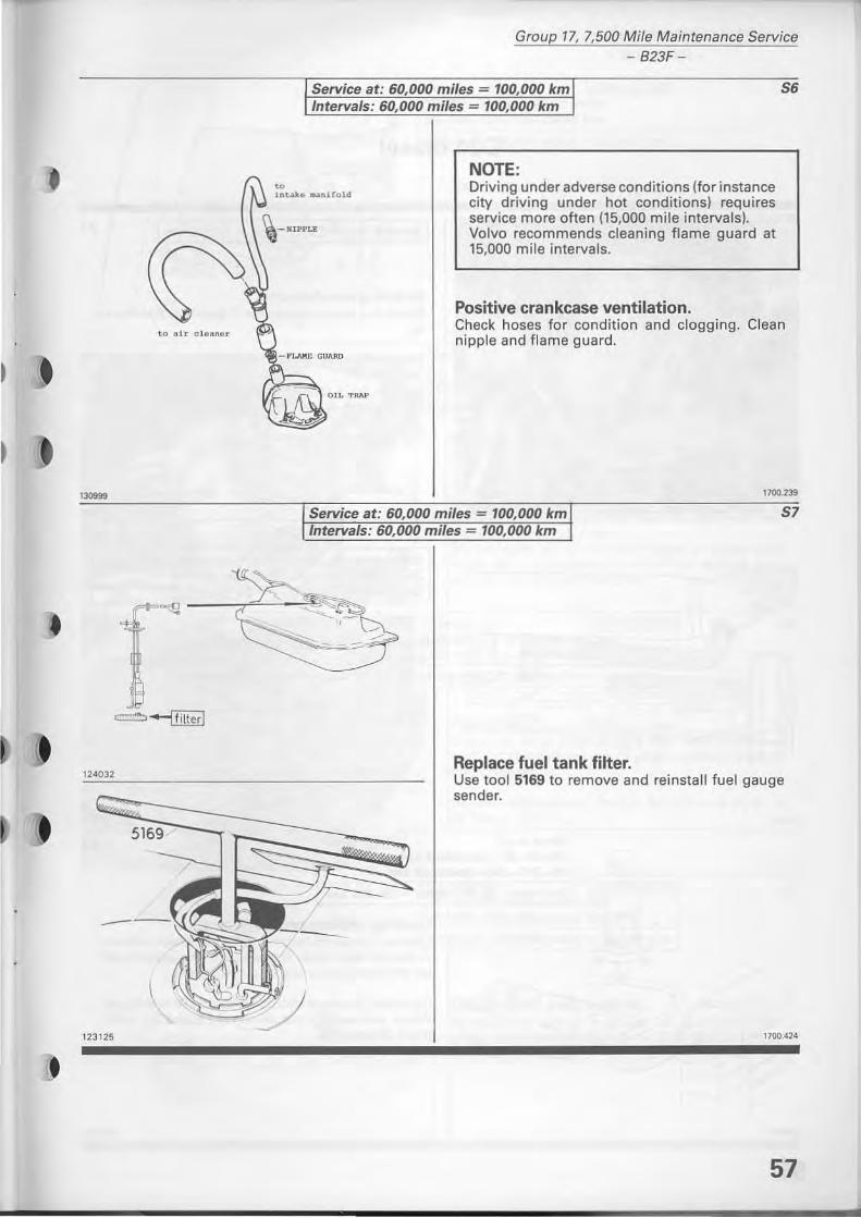
Service at: 60,000 miles = 100,000 km Intervals: 60,000 miles = 100,000 km
56
- I'J.AKE GUARD
NOTE: Driving under adverse conditions (for instance city drilling under hot conditions) requires service more often (15,000 mile intervals). Volvo recommends cleaning flame guard at 15,000 mile intervals.
Positive crankease ventilation. Check hoses for condition and clogging. Clean nipple and Ilame guard.
1700.239
Replace fuel tank filter. Use tool 5169 to remove and reinstall tuel gauge sender.
1700 .4 ~4
57
Group 17, 7,500 Mile Maintenance Service ' - 024 diesel -
129584
128186
58
024 diesel
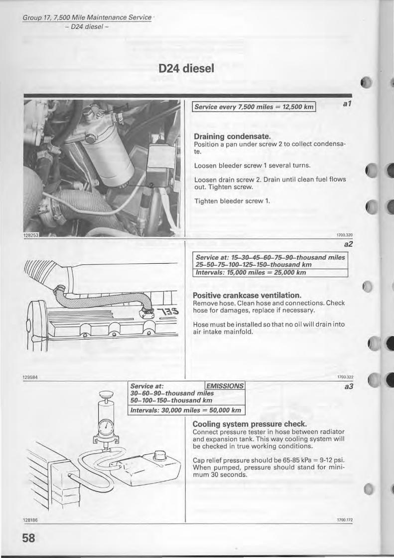
I Service every 7,500 miles = 12,500 km I al
Draining condensate. Position a pan under screw 2 to collect condensate.
Loosen bleeder screw' several turns.
Loosen drain screw 2. Drain until clean fuel flows out. Tighten screw.
Tighten bleeder screw 1.
1700.320
a2
Service at: 15-30--45-60--75-90--thousand miles 25-50--75-100--125-150--thousand km Jntervals: 15,000 miles = 25,000 km
Positive crankease ventilation. Remove hose. Clean hose and connections. Check hose for damages, replace if necessary.
Hose must be installed so that no oil will drain into air intake mainfold.
1100.322
Service at: EMISSIONS 30-60-90-thousand miles 50-100- 150-thousand km
Intervals: 30,000 miles = 50,000 km
Cooling system pressure check. Connect pressure tester in hose between radiator and expansion tank. This way cooling system will be checked in true working conditions.
Cap relief pressure should be 65-85 kPa = 9-12 psi. When pumped, pressure should stand for minimum 30 seconds.
a3
1700.\72
133229
/1'--_
'/
Group 17, 7,500 Mife Maintenance Service - 024 diesel -
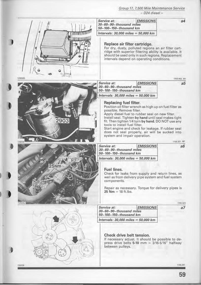
Service at: EMISSIONS a4 30-60-90-thousand miles 50- 100-150- thousand km
Interva/s: 30,000 miles = 50,000 km
Replace air filter cartridge. For dry, dusty, polluted regions an air filter cartridge with superior filtering ability is available. It should be used only in such regions. Aeplacement intervals depend on operating conditions.
Service at: 30-60-90-thousand 50-100-Interva/s: 30,000
Replacing fuel filter. Position oil fi lter wrench as high up on fuel filter as possible. Remove filter. Apply diesel fuel to rubber sea I on new filter. Install sea'- Tighten by hand until sea I makes tight fit. Then tighten l f4 turn by hand. DO NOT use any tools to install tuel filter. Start engine and check for leakage. If rubber seal does not seal properly, air will be sucked inta system and im pair operation.
Service at: 30-60-90-thousand 50-100-150- thousand km
Interva/s: 30,000 miles = 50,000 km
Fuellines.
1700.321. MI
a6
Check for leaks from supply and return lines, as weil as from delivery pipe system and fuel system components.
Repair as necessary. Torque for delivery pipes is 25 Nm = 18 ft.lbs.
at: 30-60-90-thousand
Check drive belt tension.
a7
If necessary adjust. It should be possible to depress drive belts 5-10 mm = 3f16-5f16" halfway between pu Ileys.
1100.241
59
Group 17, 7,500 Mi/e Maintenance Service - 024 diesel: valve clearance adjustment-
Valve clearance adjustment
Special toois: 5195 Pliers For removing valve depressor disc.
5196 Press tool For valve depressors
Service at: EMISSIONS 30-60-90-thousand miles 50-100-150-thousand km
Intervals: 30,000 miles - 50,000 km
Aher repairs to the cylinder head, for example grinding valves, replacing camshaft etc, valve clearance should be re-checked after driving 1000-2000 km = 600-1,200 miles.
128155
128156
NOTE: Always check valve clearance with cylinder at top dead center. Always turn 1/4 turn after top dead center to set.
128157
60
bl
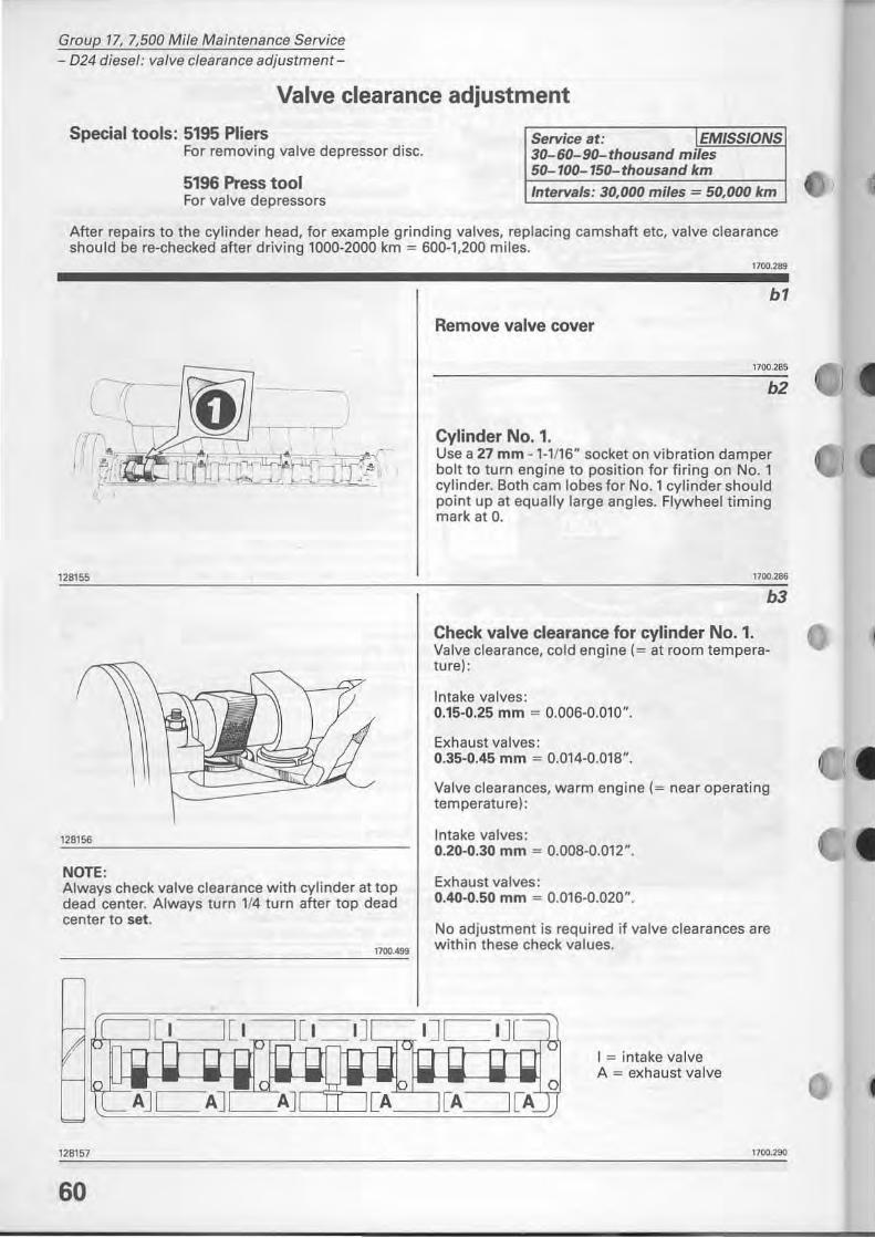
Remove valve cover
1700.285
b2
Cylinder No. 1. Use a 27 mm - 1-1 ' 16" socket on vibration damper balt to tum engine to position for firing on No. 1 cylinder. 80th cam lobes for No. 1 cylinder should point up at equally large angles. Flywheel timing mark at o.
1700.186
b3
Check valve clearance for cylinder No. 1. Valve clearance, cold engine (= at room temperature):
Intake va[ves: 0.15-0.25 mm = 0.006-0.010".
Exhaust valves: 0.35-0.45 mm = 0.014-0.018".
Valve c1earances, warm engine (= near operating temperature):
Intake valves: 0.20-0.30 mm = 0.008-0.012".
Exhaust valves: 0.40-0.50 mm = 0.016-0.020".
No adjustment is required if valve c1earances are with in these check values.
I = intake valve A = exhaust valve
1700.290
1
Group 17, 7,500 Mi/e Maintenance Service - 024 diesel: valve clearance adjustment-
----- Incorrent clearance. adjustment required -----b4
133522
128159
(
"" I i "-
I . ~, , '" \ ..i .... ~d
<f ,o
128160
118671
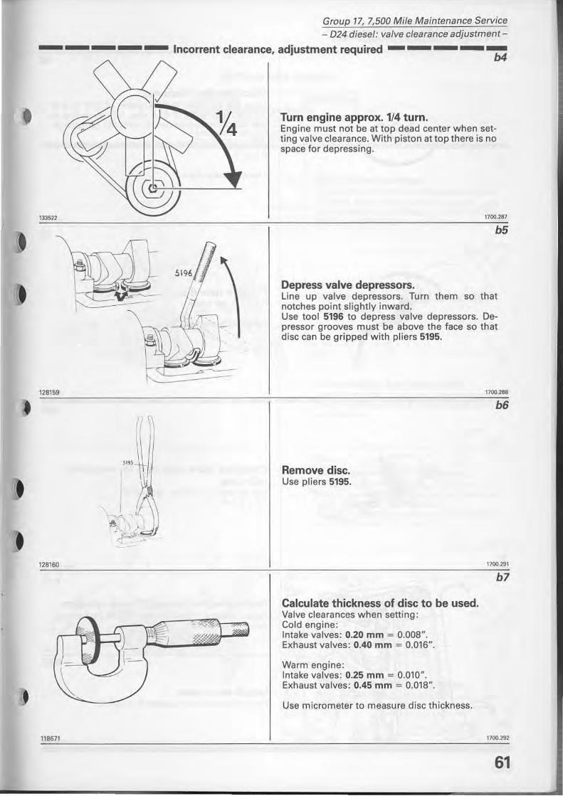
Tum engine approx. 1/4 tum. Engine must not be at top dead center when setting valve clearance. With piston at top there is no space for depressing.
1700.287
b5
Oepress valve depressors. Line up valve depressors. Turn them so that notches point slightly inward. Use tool 5196 to depress valve depressors. De· pressar grooves must be above the face so that disc can be gripped with pliers 5195.
Remove disc. Use pliers 5195.
Calculate thickness of disc to be used. Valve clearances when setting : Cald engine: Intake valves: 0.20 mm = 0.008". Exhaust valves: 0.40 mm "" 0.016".
Warm engine: lntake valves: 0.25 mm "" 0.010". Exhaust valves: 0.45 mm = 0.018".
Use micrameter to measure disc thickness.
1100.288
b6
1700.291
b7
1700.292
61
Group 17, 7,500 Mile Maintenance Service - 024 diesel: valve clearance adjustment-
3,80
128161
bB
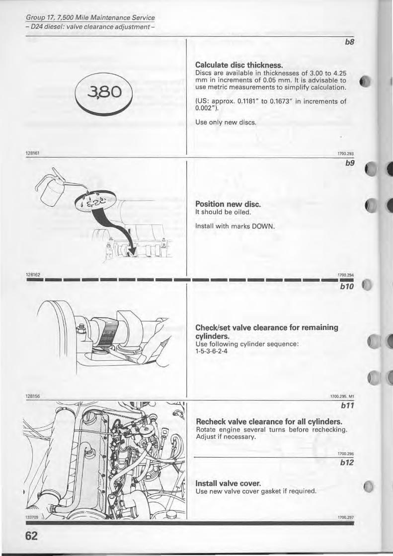
Calculate disc thickness. Discs are available in thicknesses of 3.00 to 4.25 mm in increments of 0.05 mm. It is advisable to use metric measurements to simplify calculation.
(US: approx. 0.1181" to 0.1673" in increments of 0.002").
Use on ly new discs.
Position new disc. It shou ld be oiled.
Install with marks DOWN.
1700,2'93
b9
128162 1700.294 ------------------
62
b10
Check/set valve clearance for remaining cylinders. Use following cylinder sequence : 1-5-3-6-2-4
1700.295. M1
b11
Recheck valve clearance for all cylinders. Rotate engine several turns before rechecking. Adjust if necessary.
1100.296
b12
Install valve cover. Use new valve cover gasket if required.
1100.2'97
o
13371 2
Group 17, 7,500 Mile Maintenance Service - 024 diesel: idle speeds -
Setting idle speeds
Service at: EMISSIONS 30-60-90- thousand miles 50-100-150-thousand km
Intervals: 30,000 miles = 50,000 km
e1
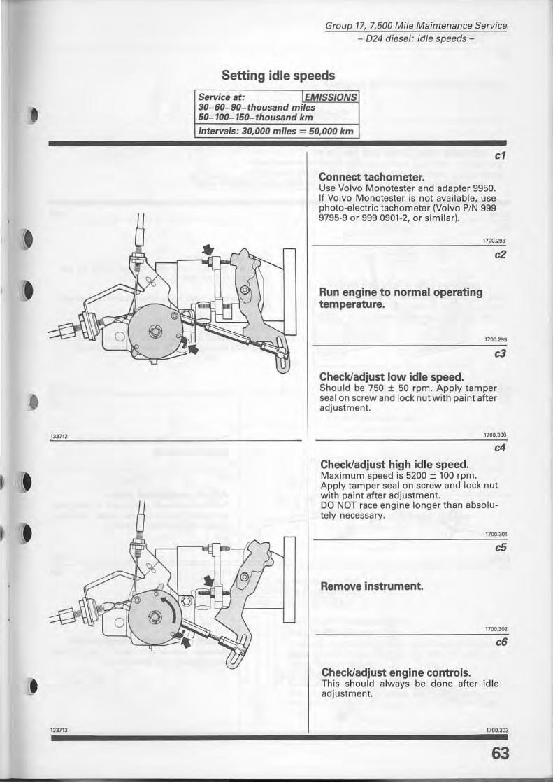
Connect tachometer. Use Volvo Monotester and adapter 9950. If Volvo Monotester is not available, use photo-electric tachometer (Volvo P/N 999 9795-9 or 999 0901-2, or similarl.
Run engine to normaloperating temperature.
Checkladjust low idle speed.
1700.298
c2
1700.799
c3
Should be 750 ± 50 rpm. Apply tamper sealon screw and lock nut with paint after adjustment.
1700.300
c4
Checkladjust high id le speed. Maximum speed is 5200 ± 100 rpm. Apply tamper sea I on screw and lock nut with paint after adjustment. DO NOT race engine long er than absolutely necessary.
1700.JDl
e5
Remove instrument.
1700.302
e6
Checkladjust engine controis. This should always be done after idle adjustment.
133713 1700.303
63

Group 17, 7,500 Mile Maintenance Service
- 024 diesel: engine controis -
Engaged
128169
128189
128190
64
Setting engine controls
Service at: 30-60-90-thousand miles 50-100-150-thousand km Interva/s: 30,000 miles 50,000 lem
Disengaged
d1
Cold start device. If engine is cold, cold start device must be disengaged before setting controis.
losen screw 1. push lever forward and turn sleeve 90°.
NOTE: DO NOT touch screw 2. If this screw is loosened, cold start device must be re-set on test bench.
Disconnect link rod at lever on injection pump.
Adjust accelerator cable
1700.326
d2
Turn cable sheath until cable is stretched but does not influence pulley position. Pulley should touch idle stop.
1700.327
d3
Check max accelerator position Depress accelerator pedal fully. Pulley should touch full speed stop.
1700.328
)
128192
128193
128194
128191
Group 17, 7,500 Mile Maintenance Service - 024 diesel: engine controls-
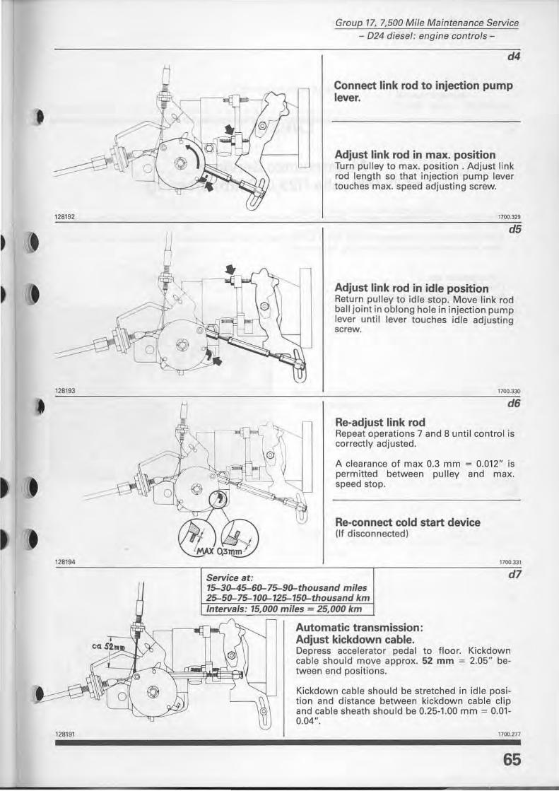
d4
Connect link rod to injection pump lever.
Adjust link rod in max. position Turn pulley to max. position. Adjust link rod length so that injection pump lever touches max. speed adjusting screw.
1100.32'9
d5
Adjust link rod in idle position Return pulley to id le stop. Move Jink rod ball joint in oblong hale in injection pump lever untif lever touches idle adjusting screw.
1700.330
d6
Re-adjust link rod Repeat operations 7 and 8 until controi is correctly adjusted.
A clearance of max 0.3 mm = 0.012" is permitted between pulley and max. speed stop.
Re-connect cold start device (If disconnected)
Service at: 15-30-45-60-75-90-thousand miles 25-50-75-100-125-150-thousand km /nterva/s: 15,000 miles = 25,000 km
Automatic transmission: Adjust kickdown cable.
1100.331
d7
Depress accelerator pedal to floor. Kickdown cable should move approx. 52 mm = 2.05" between end positions.
Kickdown cable should be stretched in idle position and distance between kickdown cable clip and cable sheath shou ld be 0.25-1.00 mm = 0.01-0.04".
1700.277
65
Group 17, 7,500 Mile Maintenance Service - Services at 75,000 miles-
Diesel
Maintenance Services at 75,000 mile (125,000 km) intervals
The following maintenance service items are to be performed at 75,000 mile (125.000 km) intervals.
Read through and understand these items so that they are known should it be necessary to perform them at an earlier interval (Le. during repairs etc).
Compression test ..... Checking/adjusting injectors ....... . .... . Replacing timing gear belts .. . . .
66
el-e10 f1-17 9
'-933
Speci.1 tool: 5191
)
j )
J
128151
Group 17, 7,500 Mi/e Maintenance Service - 024 diesel: compression test-
Compression test Service intervals:
to connect compression tester. 75,000 miles = 125,000 km
el
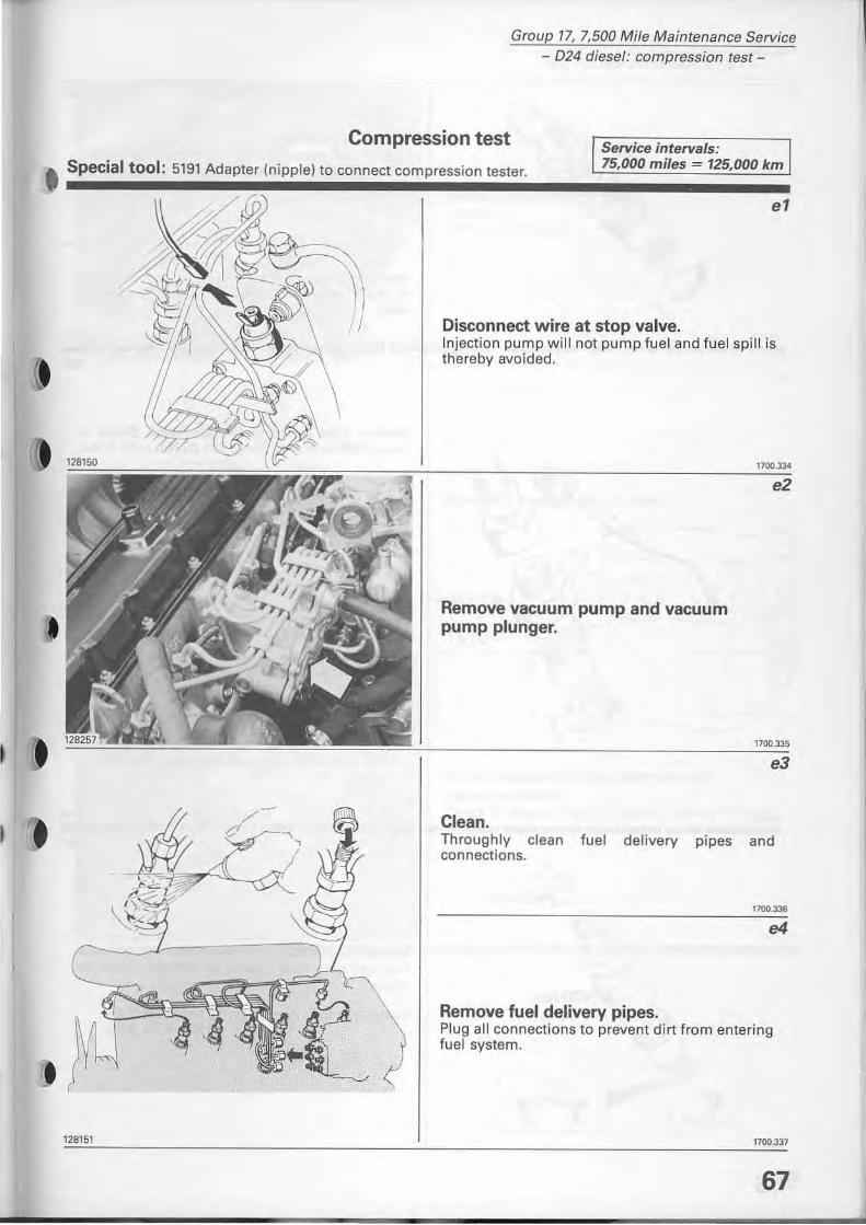
Disconnect wire at stop valve. lnjection pump w ill not pump fuel and fuel spill is thereby avoided.
Remove vacuum pump and vacuum pump plunger.
Cle.n.
1700.334
e2
Throughly clean fuel delivery pipes and connections.
1700.336
e4
Remove fuel delivery pipes. Plug all connections to prevent dirt from entering fuel system.
1100.337
67
Group 17, 7,500 Mi/e Maintenance Service - D24 diesel: compression test-
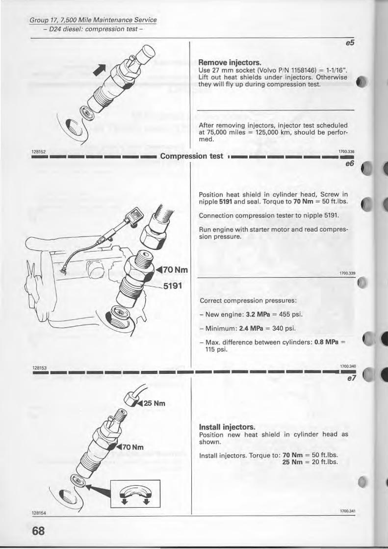
e5
Remove injectors. Use 27 mm socket (Volvo P/N 1158146) = 1-1/16". Lift out heat shields under injectors. Otherwise they will fly up during compression test.
After removing injectors, injector test scheduled at 75,000 miles = 125,000 km, should be perlormed.
128152 1700.3.38 _______ Compression test • ______ _
,..ol?" Nm
e6
Position heat shield in cylinder head, Screw in nipple 5191 and sea I. Torque to 70 Nm = 50 tUbs.
Connection compression tester to nipple 5191.
Run engine with starter motor and read compressi on pressure.
Correct compression pressures:
- New engine: 3.2 MPa = 455 psi.
- Minimum: 2.4 MPa = 340 psi.
- Max. difference between cylinders: 0.8 MPa = 115 psi.
17oo.)4(} 128153 -----------------_ ... _'" e7
~2SNm
~ + +
128154
68
Install injectors. Position new heat shield in cylinder head as shown.
lnstall injectors. Torque to: 70 Nm = 50 ft.lbs. 25 Nm = 20 ft.lbs.
1700.341
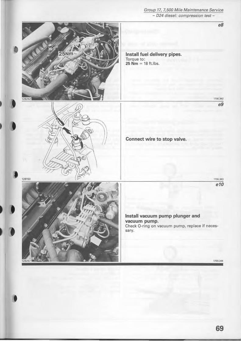
Group 17, 7,500 Mi/e Maintenance Service - D24 diesel: compression test -
Install fuel delivery pipes. Torque to: 25 Nm = 18 tU bs.
Connect wire to stop valve.
Install vacuum pump plunger and vacuum pump.
eB
1700.342
e9
1700.34]
e10
Check O-ring on vacuum pump, replace if neces· sarv·
1100.344
69
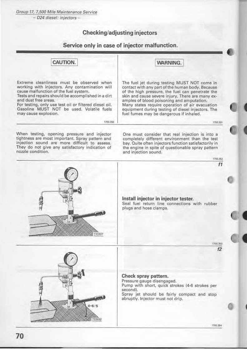
Group 17, 7,500 Mile Maintenance Service - D24 diesel: injectors -
Checking/adjusting injectors
Service only in case of injector malfunction.
I CAUTION. I
Extreme clean liness must be observed when working with injectors. Any contamination will cause malfunction of the fuel system. Tests and repairs should be accomplished in a dirt and dust tree areas. For testing, on ly use test oH or filtered dieseloil. Gasoline MUST NOT be used. Volatile fuels may cause explosion.
1700.3500
When testing, opening pressure and injector tightness are most important. Spray pattern and injection sound are more difficult to assess. They do not give any satisfactory indication of nozzle cond ition.
70
IWARNING· 1
The fuel jet during testing MUST NOT come in contact with any part of the human body. Because of the high pressure, the fuel can penetrate the skin and cause severe injury. There are many examples of blood poisoning and amputation. Many states require operation of air evacuation equipment during testing of diesel injectors. The fuel fumes may be dangerous if inhaled.
1700.151
One must consider that real injection is into a completely different environment than the test bay. Quite often injectors function satisfactorily in the engine in spite of questionable spray pattern and injection sound.
n,.",
Install injector in injector tester. Seal fuel retu rn line connections with rubber plugs and hose clamps.
fl
1700.353
Check spray pattern. Pressure gauge disengaged. Pump with short, quick strokes (4-6 strokes per second). Spray jet shou ld be fairly compact and stop abruptly. Injector must not drip.
f2
1700.354
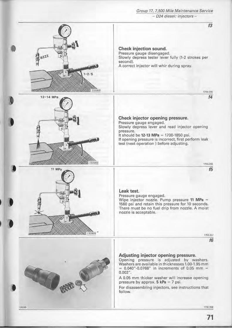
)
,
128269
Group 17, 7,500 Mile Maintenance Service - 024 diesel: injecrors-
f3
Check injection sound. Pressure gauge disengaged. Slowly depress tester lever fully (1-2 strakes per second). A carreet injector will whir during spray.
Check injector opening pressure. Pressure gauge engaged. Slowly depress lever and read injector opening pressure. It should be 12-13 MPa = 1700-1850 psi. If opening pressure is incarrect, tirst perform leak test (next operation) before adjusting.
1700.356
Leak test, Pressure gauge engaged. Wipe injector nozzle. Pump pressure " MPa = 1560 psi and retain this pressure for 10 seconds. There must be no tu el drip from nozzle. A moist nozzle is acceptable.
f5
1700.351
Adjusting injector opening pressure. Opening pressure is adjusted by washers. Washers are available in thicknesses 1.00-1.95 mm = 0.040"-0.0768" in increments of 0.05 mm = 0,002",
A 0.05 mm thicker washer will increase opening pressure by approx. 5 kPa = 7 psi.
For disassembling injectors, see instructions that follow. .
f6
1700.358
71
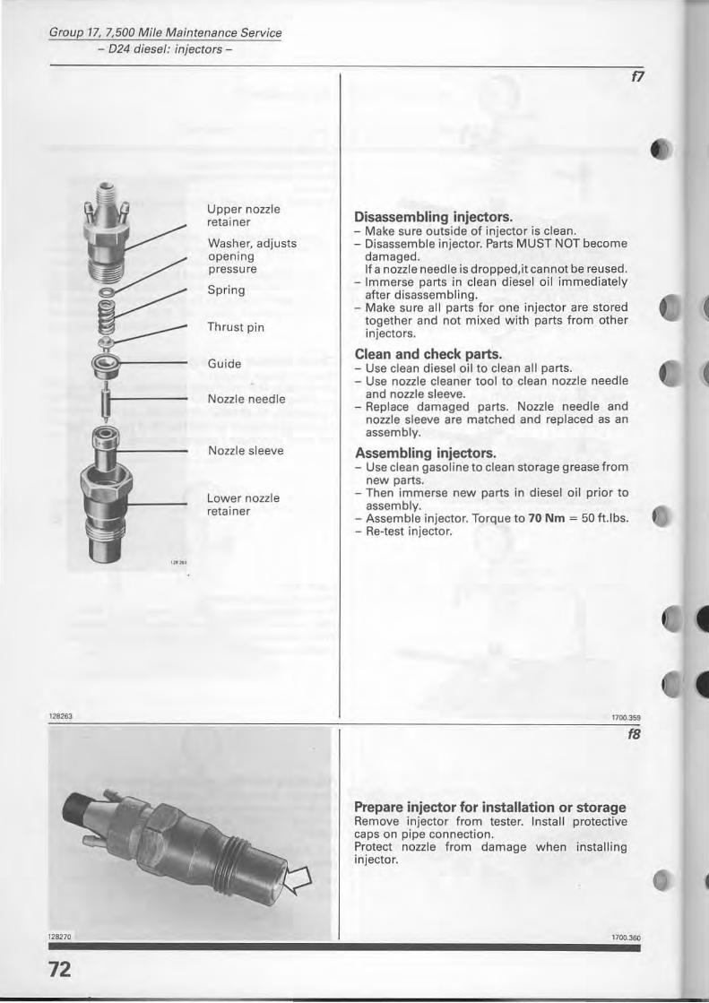
Group 17, 7,500 Mi/e Maintenance Service - D24 diesel: injectors -
128263
72
Upper nozzle reta iner
Washer, adjusts opening pressure
Spring
Thrust pin
Guide
Nozzle needle
Nozzle sleeve
Lower nozzle retainer
Disassembling injectors. - Make sure outside of injector is clean. - Disassemble injector. Parts MUST NOT become
damaged. If a nozzle needle is dropped,it cannot be reused.
- Immerse parts in clean diesel oil immediately aher disassembling.
- Make sure all parts for one injector are stored together and not mixed with parts from other injectors.
elean and check parts. - Use clean diesel oil to clean all parts. - Use nozzle cleaner tool to clean nozzle needle
and nozzle sleeve. - Replace damaged parts. Nozzle needle and
nonie sleeve are matched and replaced as an assembly.
Assembling injectors. - Use clean gasoline to clean storage grease from
new parts. - Then immerse new parts in diesel oil prior to
assembly. - Assemble injector. Torque to 70 Nm = 50 h.lbs. - Re-test injector.
f7
1100.359
Prepare injector for installation or storage Remove injector from tester. Install protective caps on pipe connection. Protect nozzle from damage when installing injector.
(8
1100.360
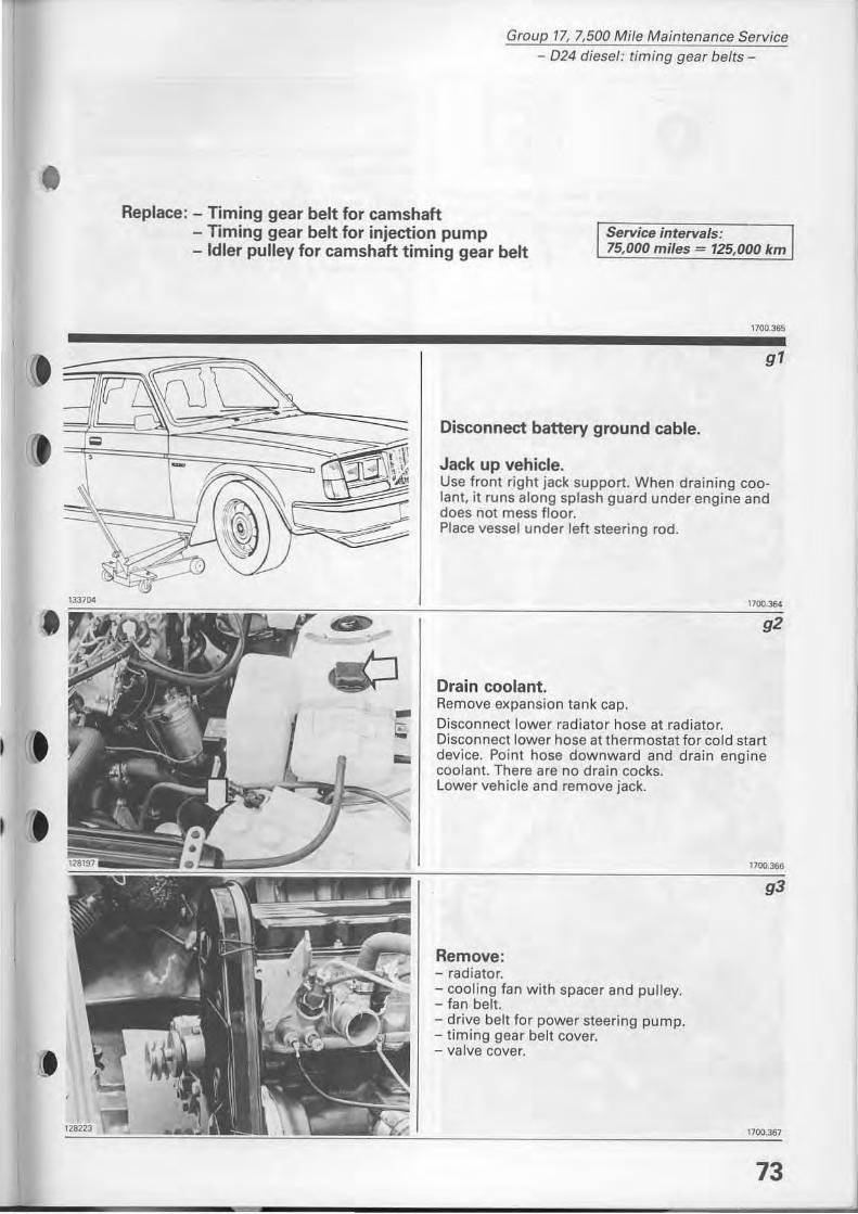
)
Group 17, 7,500 Mile Maintenance Service 024 diesel: timing gear belts
Replace: - Timing gea' belt fo, camshaft - Timing gear belt for injection pump Service intervals: - Id le, pulley fo, camshaft timing gea, belt 75,000 miles = 125,000 km
-t -
1700.365
gl
Disconnect battery ground cable.
Jack up vehicle. Use front right jack support. When draining coolan!, it runs along splash guard under engine and does not mess fl oor. Place vessel under left steering rad.
Drain coolant. Remove expansion tank cap. Disconnect lower radiato r hose at radiator. Disconnect lower hose at thermostat fo r cold start device. Point hose downwa rd and drain engine coolant. There are no drain cocks. Lower vehicle and remove jack.
Remove : - radiator. - cooling fa n with spacer and pu lley. - fan belt . - drive belt for power steering pump. - t iming gear belt cover. - va lve cover.
1100.366
11()().367
73
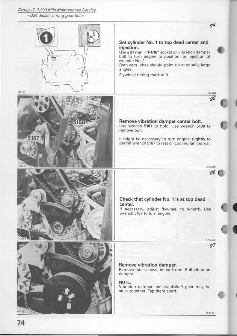
Group 77, 7,500 Mi/e Maintenance Service - 024 diesel; timing gear belts-
(
74
g4
Set cylinder No. 1 to top dead center and injectian. Use a 27 mm = 1·1116" socket on vibration damper bolt to turn eng ine to position for injection of cylinder No. 1. Both cam lobes should point up at equally large angles. Flywheel tim ing mark at O.
1700.368
Remove vibration damper center balt. Use wrench 5187 to hold. Use w rench 5188 to rem ove balt.
It might be necessary to turn engine slightly to permit wrench 5187 to rest on cooling fan journal.
Check that cylinder No. 1 is at top dead center.
1700.369
g6
If necessary, adjust flywheel to O-mark. Use wrench 5187 to turn engine.
1700.370
g7
Remove vibration damper. Remove four screws, inhex 6 mm. Pull vibration damper.
NOTE: Vi bration dam per and crankshaft gear may be stuck together. Tap them apart.
1100.371
(
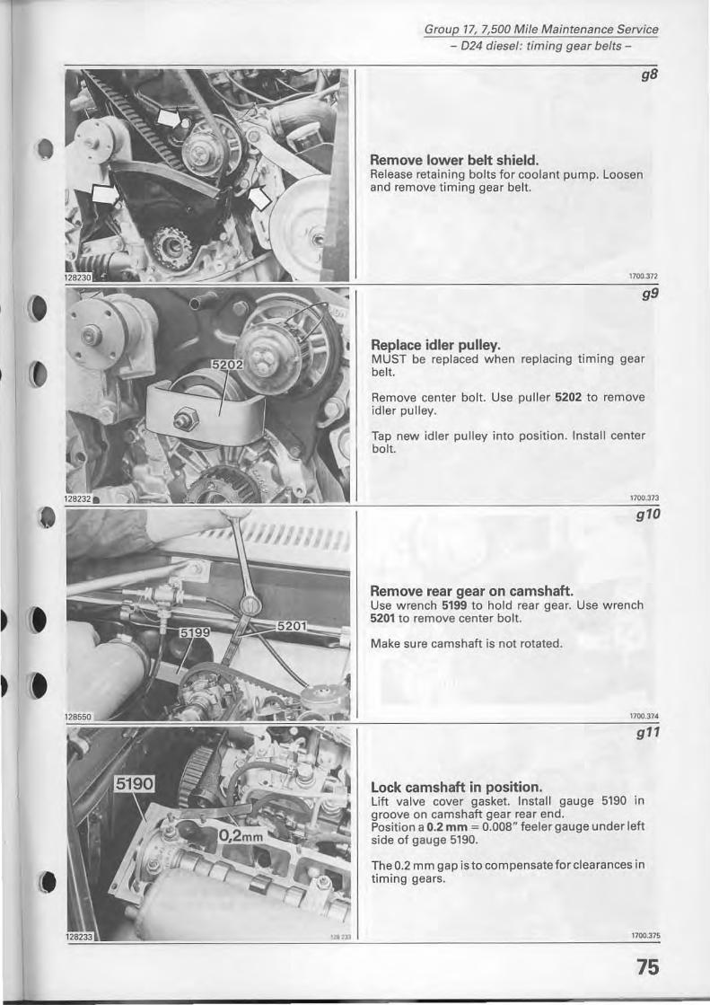
•
,
.
Group 17, 7,500 Mile Maintenance Service - 024 diesel: timing gear belts-
Remove lower belt shield. Release retaining bolts for coolant pump. Leasen and remove timing gear belt.
1700.372
Replace idler pulley. MUST be replaced when replacing timing gear belt.
Remove center bolt. Use puller 5202 to rem ove idler pulley.
Tap new id ler pulley inta position. Install center bolt.
Remove rear gear on camshaft. Use wrench 5199 to hold rear gear. Use wrench 5201 to rem ove center boh.
Make sure camshaft is not rotated.
Lock camshaft in position. lift valve covet gasket. lnstall gauge 5190 in groove on camshaft gear rear end. Position a 0.2 mm = 0.008" feeler gauge under left side of gauge 5190.
The 0.2 mm gap is to compensate for clearances in timing gears.
1100.375
75
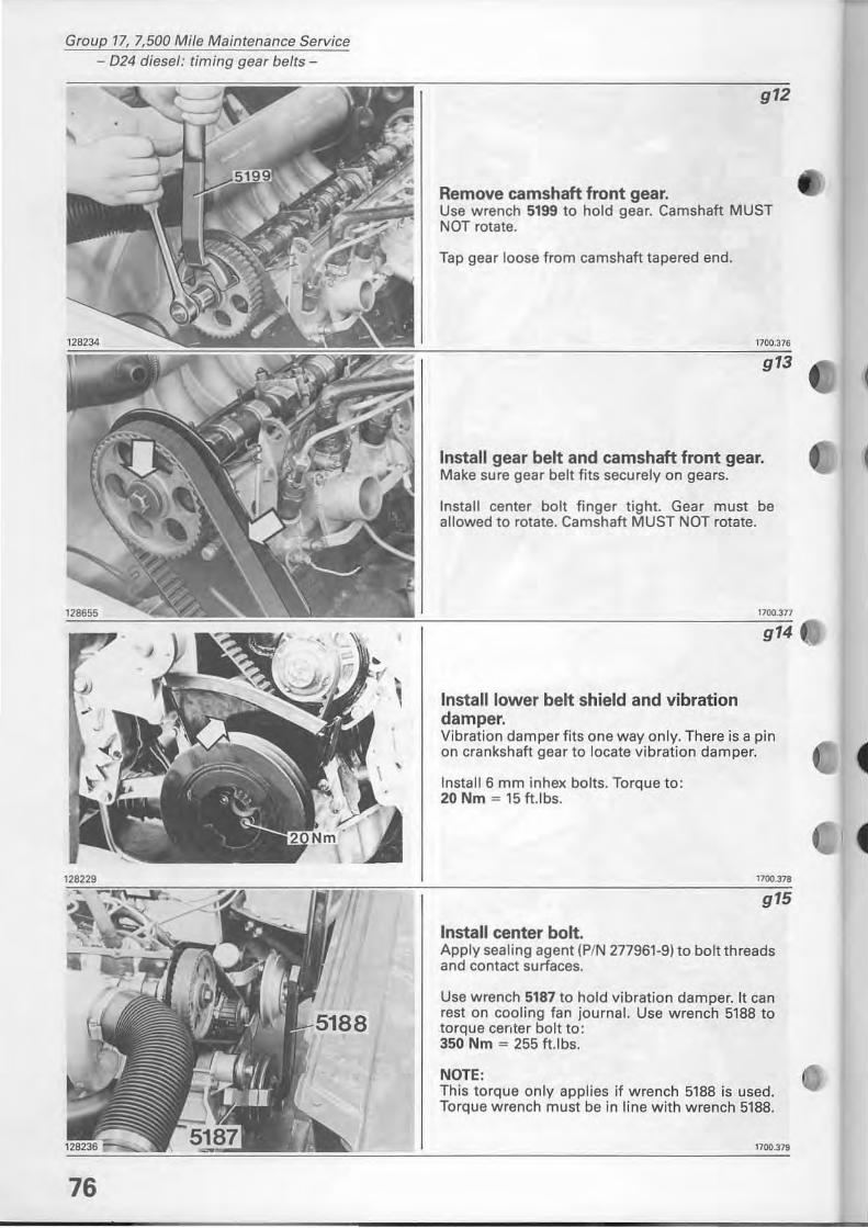
Group 17, 7,500 Mile Maintenance Service 024 diesel: timing gear belts-
76
g12
Remove camshaft front gear. Use wrench 5199 to hold gear. Camshaft MUST NOT rotate.
Tap gear loose from camshaft tapered end.
1700.376
Install gear belt and camshaft front gear. Make sure gear belt f its securely on gears.
Install center bolt f inger tight. Gear must be allowed to rotate. Camshaft MUST NOT rotate.
Install lower belt shield and vibration damper.
l1OO.3n
g14
Vibration damper fits one way on ly. There is a pin on crankshaft gear to locate vibration damper.
lnstall 6 mm inhex bolts. Torque to: 20 Nm = 15 ft .lbs.
Install center balt.
1100.318
g15
Apply sealing agent (PIN 277961-9) to bolt threads and contact surfaces.
Use wrench 5187 to hold vibration damper. It can rest on cooling fan journal. Use wrench 5188 to torque center bolt to: 350 Nm ~ 255 ft.lbs.
NOTE : This torque on ly applies if wrench 5188 is used. Torque wrench must be in line with wrench 5188.
1100.379
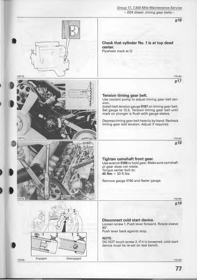
•
t
(
128175
Group 77, 7,500 Mile Maintenance Service - 024 diesel: timing gear belts-
Check that cylinder No. 1 is at top dead center. Flywheel mark at Q.
Tension timing gear belt.
g16
1700.380
g17
Use coolant pump to adjust timing gear belt tension. Install belt tension gauge 5197 on timing gear belt. Set gauge to 12.5. Tension timing gear belt until mark on plunger is flush with gauge sleeve.
Depress timing gear belt heavily by hand. Recheck timing gear belt tension. Adjust if required.
1700.381
g18
Tighten cnmshaft front gear. Use wrench 5199to hold gear. Make sure camshaft or gear does not rotate. Torque center bolt to: 45 Nm = 33 tUbs.
Remove gauge 5190 and feeler gauge.
g19
Disconnect cold start device. Leosen screw'o Push lever forward. Aotate sleeve 90°. Push lever back against stop.
NOTE: DO NOT touch screw 2.lf it is loosened. ca Id start device must be re-set on test bench.
~'2!"~69~~~~E"~9~'~9'~d~==~~~~~~~~ ____ Jl __________________________________ ~,~'OO~.~~, 77
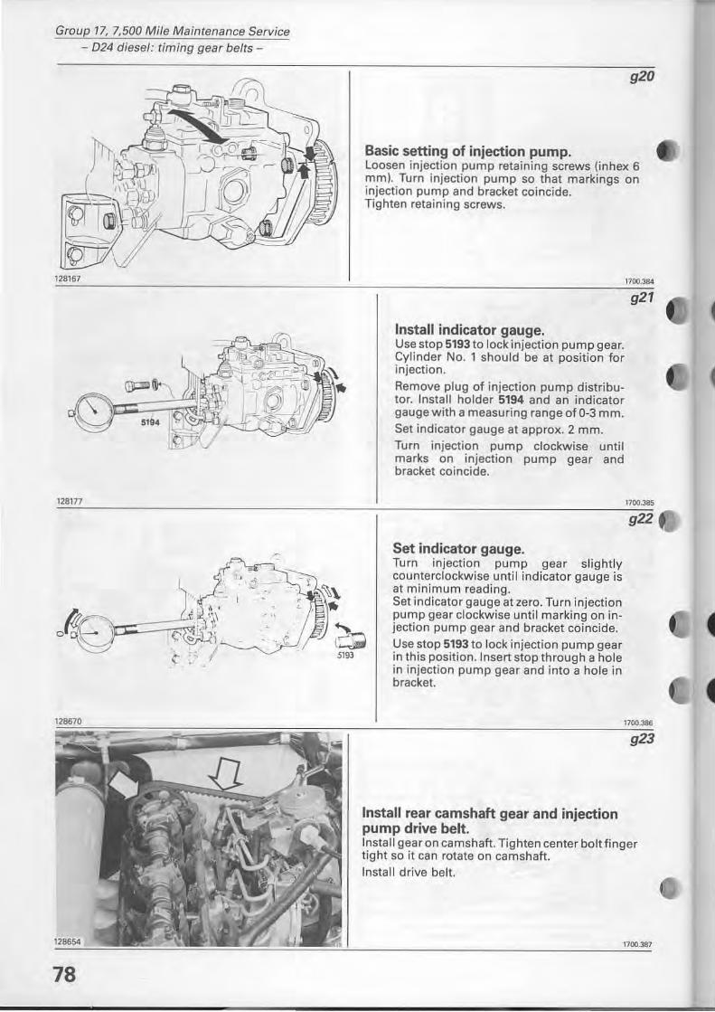
Group 17, 7,500 Mile Maintenance Service - 024 diesel: timing gear belts-
128167
128177
78
920
Basic setting of injection pump. Loosen injection pump retaining screws (inhex 6 mm). Tum injection pump so that markings on injection pump and bracket coincide. Tighten retaining screws.
Install indicator gauge. Use stop 5193 to lock injection pump gear. Cylinder No. 1 should be at position for injection.
Remove plug of injection pump distributor. Install holder 5194 and an indicator gauge with a measuring range of 0-3 mm. Set indicator gauge at approx. 2 mm. Turn injection pump clockwise until marks on injection pump gear and bracket coincide.
Set indicator gauge. Turn injection pump gear slightly counterclockwise until indicator gauge is at minimum reading. Set indicator gauge at zero. Turn injection pump gear clockwise until marking on injection pump gear and bracket coincide. Use stop 5193 to lock injection pump gear in this position.lnsert stop through a hole in injection pump gear and into a hole in brackel.
Install rear camshaft gear and injection pump drive belt.
1700.384
921
1700.385
922
Install gear on camshaft. Tighten center bolt finger tight so it can rotate on camshaft. Install drive bell.
1700.387
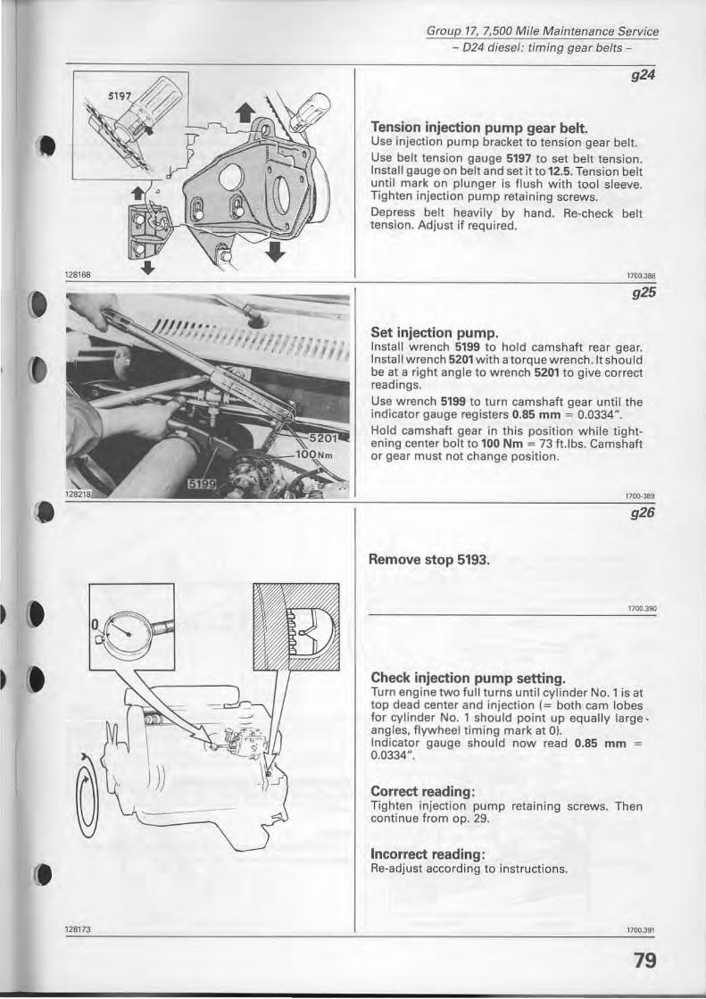
•
•
)) --
e. 1281 73
Group 17, 7,500 Mile Maintenance Service - D24 diesel: timing gear belts-
g24
Tension injection pump gear belt. Use injection pump bracket to tension gear belt . Use belt tension gauge 5197 to set belt tension. Install gauge on belt and set it to 12.5. Tension belt until mark on plunger is flush with too I sleeve. Tighten injection pump retaining screws. Depress belt heavily by hand. Re-check belt tension. Adjust if required.
1700.388
g25
Set injection pump. lnstall wrench 5199 to hold camshaft rear gear. Install wrench 5201 with a torquewrench.lt should be at a right angle to wrench 5201 to give correct readings.
Use wrench 5199 to turn camshaft gear until the indicator gauge registers 0.85 mm = 0.0334". Hold camshaft gear in this position while tightening center balt to 100 Nm = 73 ft.lbs. Camshaft or gear must not change position.
",.'" g26
Remove stop 5193.
1700.390
Check injection pump setting. Turn engine two full turns until cylinder No. 1 is at top dead center and injection (= both cam lobes for cylinder No. 1 should point up equally large angles. flywheel timing mark at O). Indicator gauge should now read 0.85 mm = 0,0334",
Correct reading: Tighten injection pump retaining screws. Then continue from ap. 29.
Incorrect reading : Re-adjust according to instructions.
1700.391
79
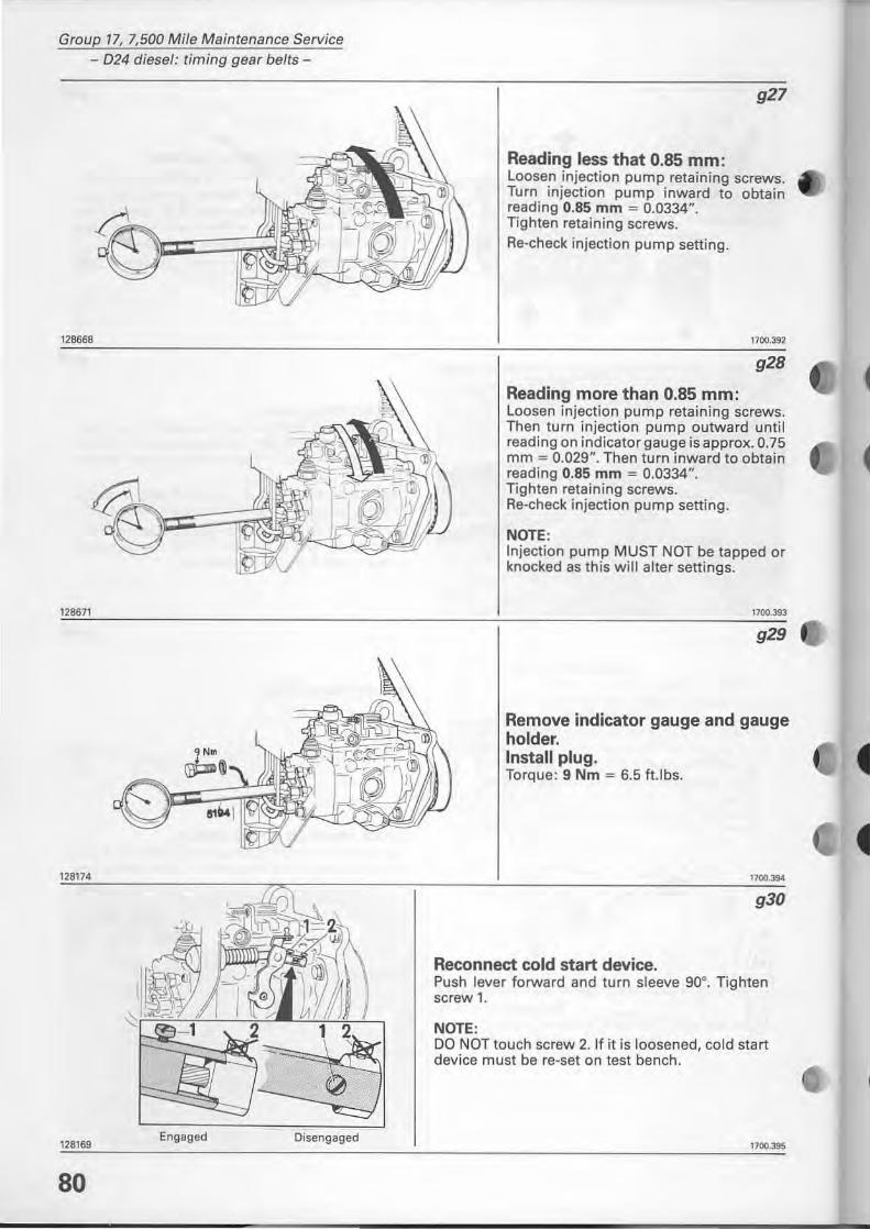
Group 17, 7,500 Mile Maintenance Service - 024 diesel: timing gear belts-
''''''
128671
128169 Engaged Oisengaged
80
927
Reading less that 0.85 mm: Loosen injection pump retaining screws. Turn injection pump inward to obtain reading 0.85 mm = 0.0334". Tighten retaining screws. Re-check injection pump setting.
1700.392
928
Reading more than 0.85 mm: Loosan injection pump retaining screws. Then turn injection pump outward until reading on indicator gauge is approx. 0.75 mm = 0.029". Then turn inward to obtain reading 0.85 mm = 0.0334". Tighten retaining screws. Re-check injection pump setting.
NOTE: Injection pump MUST NOT be tapped or knocked as this will alter settings.
929
Remove indicator gauge and gauge holder. Install plug. Torque: 9 Nm = 6.5 ft.lbs.
1700.394
930
Reconnect cold start device. Push lever forward and turn sleeve 90°. Tighten screw 1.
NOTE: DO NOT touch screw 2. If il is loosened, cald start device must be re-set on test bench.
1700.395
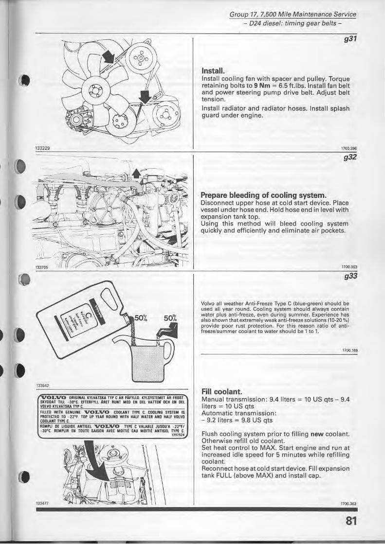
e.
•
133229
50% 50%
~
133542
L'VO ORI&INAL IC'flVÄTSICA lY. C ÄR • .lFmD. IC'fLSYSTEMET AR FROST· SKYDDAT TIll -30"C. fnERFYLl ARET RI/NT MED EN Dft VAnEIJ OCH El OH VOLVO lllVATSICA TY, C, FILLED WITH 6fNI/INE VOLVO CDOWT TYP( C. CDOllNG SYSTEM IS PIIDTECTED TO _ZZ"F . TO' U' rEAII ROUlID WITH HAlf WATER AND HAlt VOLVO CDDLlNT lYPf. t . UMPlI OE UOUIDE AIITIGH VOLVO TYPf. t VALABlE JUSOU'" - ZZ"FI - JO"t, UMP\JR EN TDUTE SAlSON "VEC Momt EAU MOITlt AIITIGH lYPf. t ,
InIS!4
133477
Group 17, 7,500 Mile Maintenance Service - 024 diesel: timing gear belts-
g31
Install. Install cooling fan with spacer and pulley. Torque retaining balts to 9 Nm = 6.5 ft.lbs.lnstall fan belt and power steering pump drive belt. Adjust belt tension.
Install radiator and radiator hoses. Install splash guard under engine.
1700.396
g32
Prepare bleeding of cooling system. Disconnect upper hose at cold start device. Place vessel under hose end. Hold hose end in level with expansion tank top. Using this method w ill bleed cooling system quickly and efficiently and eliminate air pockets.
1700,363
g33
Volvo all weather Anti-Freeze Type C (blue-green) should be used all year round. Cooling system should always conlain waler plus anli-freeze, even during summer. Experienee has also shown that extremely weak anti·freeze solutions {10-20 0/0) provide poor rust proteetion. For this reason ratio 01 antiIreezefsummer coolant lo water should be l to l.
1700.169
Fill coolant. Manual transmission: 9.4 liters = 10 US qts - 9.4 liters = 10 US qts Automatic transmission: - 9.2 liters = 9.8 US qts
Flush cool ing system prior to filling new coolant. Otherwise refill old coolant. Set heat controi to MAX. Start engine and run at increased idle speed for 5 minutes while refilling coolant. Reconnect hose at cold start device. Fill expansion tank FULL (above MAX) and install cap.
1100.362
81
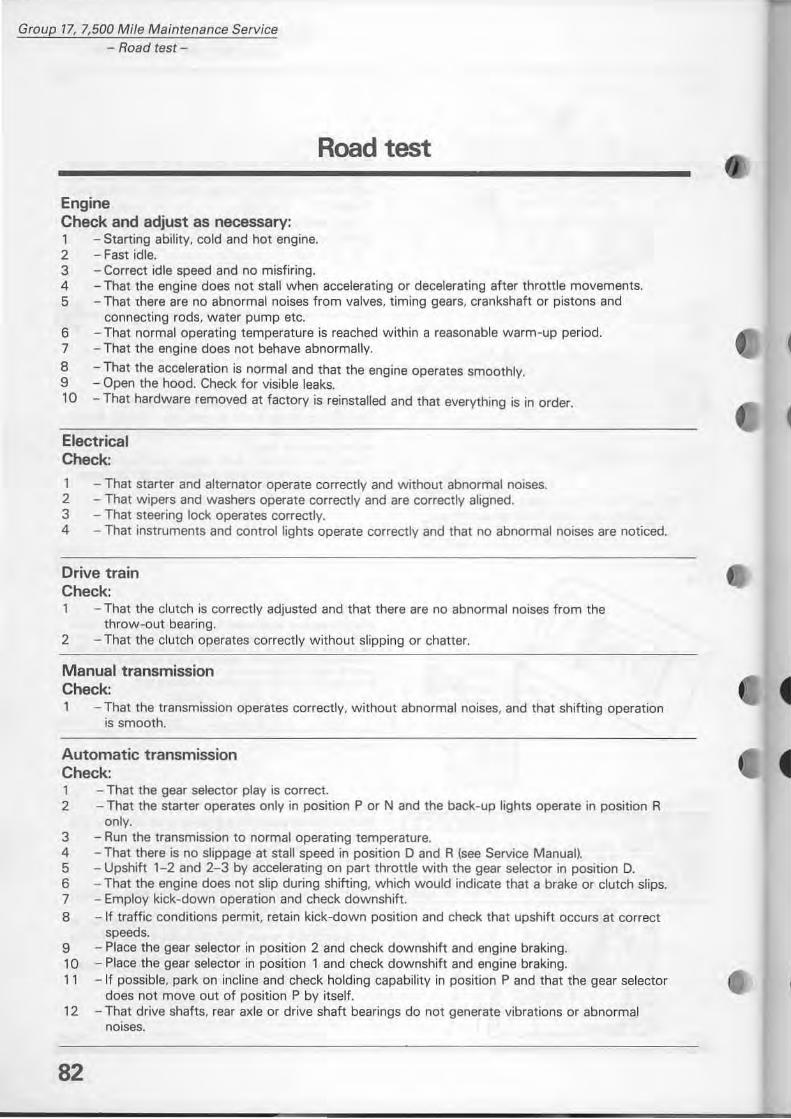
Group 17, 7,500 Mi/e Maintenance Service - Road test-
Engine Check and adjust as necessary: 1 - Starting ability, cold and hot engine. 2 - Fast id le. 3 - Correct idle speed and no misfiring.
Road test
4 - That the engine does not stall when accelerating or decelerating after throttle movements. 5 - That there are no abnormal noises from valves. timing gears, crankshaft or pistans and
connecting rads, water pump etc. 6 - That normaloperating temperature is reached within a reasonable warm ~up period. 7 - That the engine does not behave abnormally.
8 - That the acceleration is normal and that the engine operates smoothly. 9 - Open the hood. Check for visible leaks. la - That hardware removed at factory is reinstalled and that everything is in order.
Electrical Check:
1 - That starter and alternator operate correctly and w ithout abnormal noises. 2 - That wipers and washers operate correctly and are correctly aligned. 3 - That steering lock operates correctly. 4 - That instruments and controllights operate correctly and that no abnormal noises are noticed.
Drive train Check:
- That the clutch is correctly adjustEld and that there are no abnormal noises from the throw-out bearing.
2 - That the clutch operates correctly without slipping or chatter.
Manual transmission Check:
- That the transmission operates correctly, without abnormal noises. and that shifting operation is smooth.
Automatic transmission Check: l - That the gear selector play is correct. 2 - That the starter operates only in position P or N and the back-up lights operate in position R
only. 3 - Run the transmission to normaloperating temperature. 4 - That there is no slippage at stall speed in position D and R (see Service Manuall. 5 - Upshift 1- 2 and 2- 3 by accelerating on part throttle with the gear selector in position D. 6 - That the engine does not slip during shifting, which would indicate that a brake or clutch slips. 7 - Employ kick-down operation and check downshift. 8 -If traffic conditions permi\, retain kick-down position and check that upshift occurs at correct
speeds. 9 - Place the gear selector in position 2 and check downshift and engine braking. 10 - Place the gear selector in position 1 and check downshift and engine braking. 11 - If possible, park on incline and check holding capability in position P and that the gear selector
does not move out of position P by itself. 12 - That drive shafts. rear axle or drive shaft bearings do not generate vibrations or abnormal
noises.
82
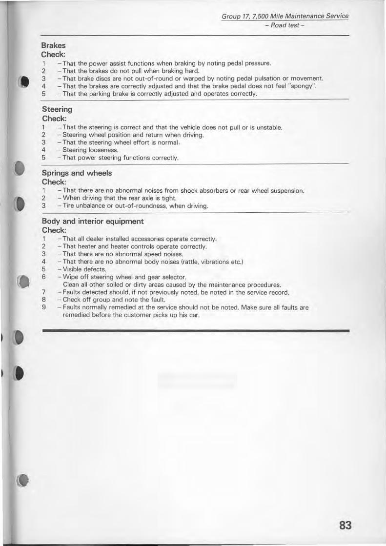
•
Group 17, 7,500 MiJe Maintenance Service - Road test -
Brakes Check: 1 2 J 4 5
- That the power assist functions when braking by noting pedal pressure. - That the brakes do not pull when braking hard. - That brake discs are not out-of-round or warped by noting pedal pulsation or movement. - That the brakes are correctly adjusted and that the brake pedal does not feel "spongy". - That the parking brake is correctly adjusted and operates correctly.
Steering Check: 1 - lhat the steering is correct and that the vehicle does not pull or is unstable. 2 - Steering wheel position and return when driving. 3 - That the steering wheel eftort is normal. 4 - Steering looseness. 5 - That power steering functions correctly.
Springs and wheels Check: 1 - That there are no abnormal noises from shock absorbers or rear wheel suspension. 2 - When driving that the rear axle is ttght. 3 - Tire unbalance or out-of-roundness, when driving.
Body and interior equipment Check: 1 - That all dealer installed accessories operate correctly. 2 - That heater and heater controis operate correctly. 3 - That there are no abnormal speed noises. 4 - That there are no abnormal body noises (rattle, vibrations etc.) 5 - Visible defects. 6 - Wipe off steering wheel and gear seleetor.
Clean all other soiled or dirtyareas caused by the maintenance procedures. 7 - Faults detected should, if not previously noted, be noted in the service record. 8 - Check off group and note the faul1. 9 - Faults normally remedied at the service should not be noted. Make sure all faults are
remedied before the customer picks up his ear.
83
• • •
•
VOLVO SUPPORTS VOlUNTARY MECHANIC CERTlFICATlON
BY THE N.I .A.S.E .
(USA ONlYj
Service literature
Your most important
special tool