Embed Size (px)
Citation preview

Service Manual for ElectronicPrecision Balances series
434Version 1.0 7/97
434-SH-e-9710
434-SH-e-97102
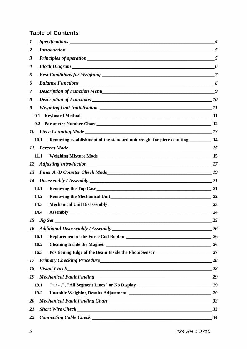
Table of Contents
1 Specifications __________________________________________________________4
2 Introduction ___________________________________________________________5
3 Principles of operation ___________________________________________________5
4 Block Diagram _________________________________________________________6
5 Best Conditions for Weighing _____________________________________________7
6 Balance Functions ______________________________________________________8
7 Description of Function Menu_____________________________________________9
8 Description of Functions ________________________________________________10
9 Weighing Unit Initialisation _____________________________________________11
9.1 Keyboard Method_________________________________________________________ 11
9.2 Parameter Number Chart __________________________________________________ 12
10 Piece Counting Mode ___________________________________________________13
10.1 Removing establishment of the standard unit weight for piece counting__________ 14
11 Percent Mode _________________________________________________________15
11.1 Weighing Mixture Mode _________________________________________________ 15
12 Adjusting Introduction __________________________________________________17
13 Inner A /D Counter Check Mode__________________________________________19
14 Disassembly / Assembly _________________________________________________21
14.1 Removing the Top Case__________________________________________________ 21
14.2 Removing the Mechanical Unit____________________________________________ 22
14.3 Mechanical Unit Disassembly _____________________________________________ 23
14.4 Assembly ______________________________________________________________ 24
15 Jig Set _______________________________________________________________25
16 Additional Disassembly / Assembly ________________________________________26
16.1 Replacement of the Force Coil Bobbin _____________________________________ 26
16.2 Cleaning Inside the Magnet ______________________________________________ 26
16.3 Positioning Edge of the Beam Inside the Photo Sensor ________________________ 27
17 Primary Checking Procedure_____________________________________________28
18 Visual Check __________________________________________________________28
19 Mechanical Fault Finding _______________________________________________29
19.1 "+ / - .", "All Segment Lines" or No Display ________________________________ 29
19.2 Unstable Weighing Results Adjustment ____________________________________ 30
20 Mechanical Fault Finding Chart _________________________________________32
21 Short Wire Check ______________________________________________________33
22 Connecting Cable Check ________________________________________________34
434-SH-e-9710 3
23 Plate Bearing / Coupling Link Check ______________________________________35
24 Beam Stopper Adjustment _______________________________________________36
25 A / D Converter Check __________________________________________________38
26 Initialisation of EEPROM _______________________________________________39
27 Linearity Adjusting_____________________________________________________40
27.1 Linearity Adjusting Procedure____________________________________________ 40
27.2 Adjusting Masses Chart _________________________________________________ 41
28 Span Adjusting ________________________________________________________42
28.1 Adjusting Masses Chart _________________________________________________ 42
28.2 Adjusting Mass Tolerance Collection ______________________________________ 44
28.3 Disable the Span Adjusting Function_______________________________________ 46
29 Cornerload Adjustment _________________________________________________46
29.1 Cornerload Adjustment Masses ___________________________________________ 46
30 Electronic Fault Finding ________________________________________________48
30.1 Power Check___________________________________________________________ 48
30.2 EEPROM Check _______________________________________________________ 48
30.3 Voltage Check__________________________________________________________ 49
31 Electronic Fault Finding Charts __________________________________________50
32 Wave Form Check _____________________________________________________55
33 RS-232 C Interface _____________________________________________________57
33.1 Interface Specifications __________________________________________________ 57
33.2 Output Format _________________________________________________________ 59
33.3 Output Data Mode ______________________________________________________ 60
33.4 External Control Commands _____________________________________________ 61
33.5 Cabling Diagrams_______________________________________________________ 62
34 Installation of the Air Shield Case (OMJ-2 Option)___________________________63
35 Troubleshooting _______________________________________________________64
36 KERN 434 Series Parts List ______________________________________________68
37 Balance drawings ____________________________ Fehler! Textmarke nicht definiert.
434-SH-e-97104
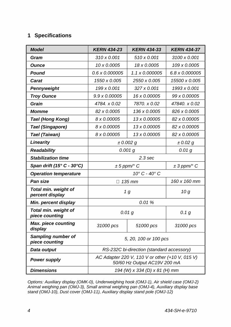
1 Specifications
Model KERN 434-23 KERN 434-33 KERN 434-37
Gram 310 x 0.001 510 x 0.001 3100 x 0.001
Ounce 10 x 0.0005 18 x 0.0005 109 x 0.0005
Pound 0.6 x 0.000005 1.1 x 0.000005 6.8 x 0.000005
Carat 1550 x 0.005 2550 x 0.005 15500 x 0.005
Pennyweight 199 x 0.001 327 x 0.001 1993 x 0.001
Troy Ounce 9.9 x 0.00005 16 x 0.00005 99 x 0.00005
Grain 4784. x 0.02 7870. x 0.02 47840. x 0.02
Momme 82 x 0.0005 136 x 0.0005 826 x 0.0005
Tael (Hong Kong) 8 x 0.00005 13 x 0.00005 82 x 0.00005
Tael (Singapore) 8 x 0.00005 13 x 0.00005 82 x 0.00005
Tael (Taiwan) 8 x 0.00005 13 x 0.00005 82 x 0.00005
Linearity ± 0.002 g ± 0.02 g
Readability 0.001 g 0.01 g
Stabilization time 2.3 sec
Span drift (15° C - 30°C) ± 5 ppm/° C ± 3 ppm/° C
Operation temperature 10° C - 40° C
Pan size ∅ 135 mm 160 x 160 mm
Total min. weight ofpercent display
1 g 10 g
Min. percent display 0.01 %
Total min. weight ofpiece counting
0.01 g 0.1 g
Max. piece countingdisplay
31000 pcs 51000 pcs 31000 pcs
Sampling number ofpiece counting
5, 20, 100 or 100 pcs
Data output RS-232C bi-direction (standard accessory)
Power supply AC Adapter 220 V, 110 V or other (+10 V, 015 V)50/60 Hz Output AC19V 200 mA
Dimensions 194 (W) x 334 (D) x 81 (H) mm
Options: Auxiliary display (OMK-0), Underweighing hook (OMJ-1), Air shield case (OMJ-2)Animal weighing pan (OMJ-3), Small animal weighing pan (OMJ-4), Auxiliary display basestand (OMJ-10), Dust cover (OMJ-11), Auxiliary display stand pole (OMJ-12)
434-SH-e-9710 5
2 Introduction
This Maintenance Manual covers three models from the KERN 434 series, theKERN 434-23, KERN 434-33 and KERN 434-37. Please read this MaintenanceManual and the owner’s Instruction Manual fully before beginning anymaintenance work.
The KERN 434 series precision balances are the products of years of research,development, design and in-field testing. They incorporate the latest advancesin mechanical and electronic engineering and offer the highest standard ofreliability, easy to use functions and rugged durability.
3 Principles of operation
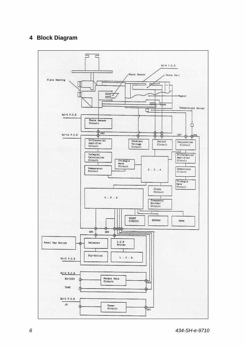
The KERN 434 series precision balances work on the principle of "ForceCompensation". Any change in the load on the weighing pan causes the Beam topivot on fulcrum Plate Bearings (see Block Diagram page 4). Attached to this Beamis a coil wound with fine wire, called the "Force Coil Bobbin", which floats in apermanent magnet. At the end of the Beam there is a small notch which allows lightfrom a Light-Emitting Diode (LED) to pass through to a Photo Sensor (LightMeasuring Diode). At zero weight, the light detected by the Photo Sensor is exactlyequal to the light emitted by the LED.
When the end of the beam is forced up by the leverage exerted from a mass placedon the weighing pan, the Photo Sensor detects a change in the position of the beamand the attached Force Coil Bobbin, because the light reaching the Photo Sensorhas become less than that emitted by the LED. The balance then feeds the ForceCoil Bobbin with more voltage, which increases the magnetic power and pulls theBobbin downward until the light reaching the Photo Sensor is once again equal tothe light emitted by the LED. This is accomplished by a Differential Amplifier, a filterand an Analogue/Digital (A/D) Converter receiving photo current from the PhotoSensor, converting it to voltage and boosting it back to the Force Coil Bobbin.
The electrical current flowing through the Force Coil Bobbin generates a voltageproportional to the load weight on the pan. This is read back through the DifferentialAmplifier and filter, then the A/D Converter digitalises this voltage. The resultingvalue is then counted and fed to the microprocessor (CPU). The CPU performs amultitude of commands and mathematical operations in conjunction with parameterand adjusting information stored in Random Access Memory (RAM). Finally, theresults are displayed on the Liquid Crystal Display (LCD) or sent to the RS-232 CInterface.
434-SH-e-97106
4 Block Diagram
434-SH-e-9710 7
5 Best Conditions for Weighing
1. Never turn off the power switch or disconnect the AC adapter when in use.
2. When making a measurement, always place the sample in the centre of theweighing pan. Slight errors may result if the sample is not near the centre ofthe pan.
3. Make sure the balance is level by using the level vial and the adjustable feeton the bottom.
4. Install the balance in a controlled environment.
A) The weighing room should be kept clean, dry and free of cigarettesmoke.
B) Protect the balance from drafts (air currents). Use a draft shield ifnecessary.
C) Maintain the ambient temperature to ±±±± 3° C.D) Maintain the ambient humidity to ±±±± 10 %.E) If larger changes in temperature or humidity occur, re-calibrate the
balance.F) The balance table should be level and free from excessive vibration.
Corners of rooms are less prone to vibration.G) Do not expose the balance to direct sunlight or radiated heat. Keep away
from windows, heaters, hot plates, flames, fans, air conditioners, etc.H) Allow hot or cold sample containers to come to ambient temperature
before weighing.I) Discharge any statically charged sample before weighing.J) Do not expose the balance to corrosive gases.
5. Magnetised samples cannot be weighed accurately on an electronicbalance. Keep equipment containing magnets away from the balance.
6. Make certain that the AC power supply is free from electrical disturbances.
7. Clean the balance with a damp cloth only (no solvents).
8. Always warm-up the balance before use or leave on Stand-by (display off)overnight.
9. Always handle the balance with care during use or when moving or storing.
434-SH-e-97108
6 Balance Functions
Sampling Time Function (SAP): The SAP function allows the balance to adapt to
the surrounding environmental conditions. The SAP should be adjusted to a small
value for corresponds to the "integration time" in seconds that the balance is using to
display readings.
Stability Indicator Function (STb): All KERN 434 series balances use the star (Η)
symbol to indicate stability. When the Η appears on the display, the balance has not
yet stabilised. When the Η disappears from the display, the balance is stable. The
weight reading should be made only after the Η has disappeared from the display
and the indicator on the display for different sample types and weighing conditions.
Small values for STb require very stable conditions before the Η disappears from the
display and large values allow the Η to disappear under more reliable conditions
such as animal weighing.
Adjusting (Cal): The Cal function is used to perform a Span Adjusting on the
balance. See Span Adjusting page 35 for the steps required for this procedure.
Weighing Unit Selection (Uni): The Uni function is used to select and lock in
different weighing units. Uni-1 locks in grams or another unit and prevents switching
between units. Uni-2 allows the user to switch from grams to another unit by pushing
the U key. See Weighing Unit Initialisation page 9 to select or change the available
weighing units.
Output Data Mode (oUT): The oUT function is used to change the output data
mode when using the RS-232 C interface. See RS-232 C Interface page 54.
RS-232 C Mode (rS): The rS function allows you to switch between 8 bit non-parity
(8N1) and 7 bit even-parity (7E1)when using the RS-232 C Interface. See RS-232 C
Interface page 58 - 63
Baud Rate Speed (rSS): The rSS function changes the baud rate speed when using
the RS-232 C Interface. See RS-232 C Interface page 8 for the steps required for
this procedure.
Auto-Start Mode (AST-ON): If auto-start mode is on, the balance will be weighing
position immediately without pressing the ON/STBY key.
434-SH-e-9710 9
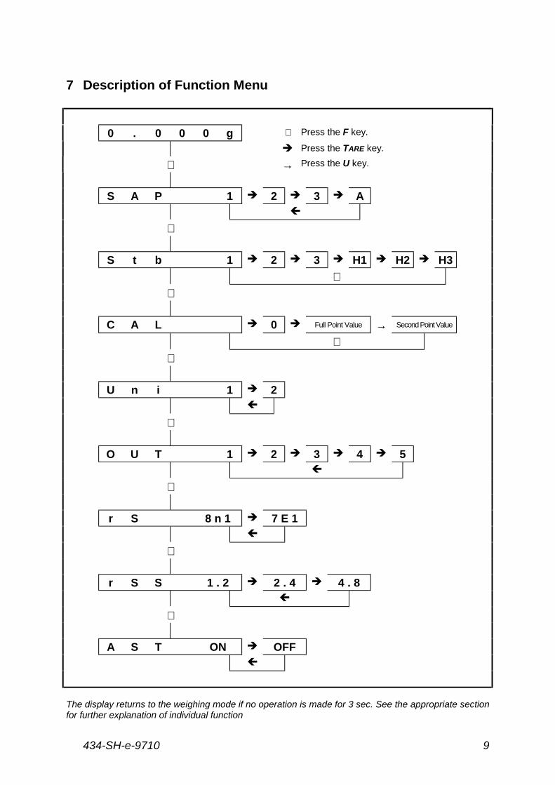
7 Description of Function Menu
0 . 0 0 0 g ⇓ Press the F key.
! Press the TARE key.
⇓ → Press the U key.
S A P 1 ! 2 ! 3 ! A"
⇓
S t b 1 ! 2 ! 3 ! H1 ! H2 ! H3
⇐⇓
C A L ! 0 ! Full Point Value → Second Point Value
⇐⇓
U n i 1 ! 2"
⇓
O U T 1 ! 2 ! 3 ! 4 ! 5"
⇓
r S 8 n 1 ! 7 E 1"
⇓
r S S 1 . 2 ! 2 . 4 ! 4 . 8"
⇓
A S T ON ! OFF"
The display returns to the weighing mode if no operation is made for 3 sec. See the appropriate sectionfor further explanation of individual function
434-SH-e-971010
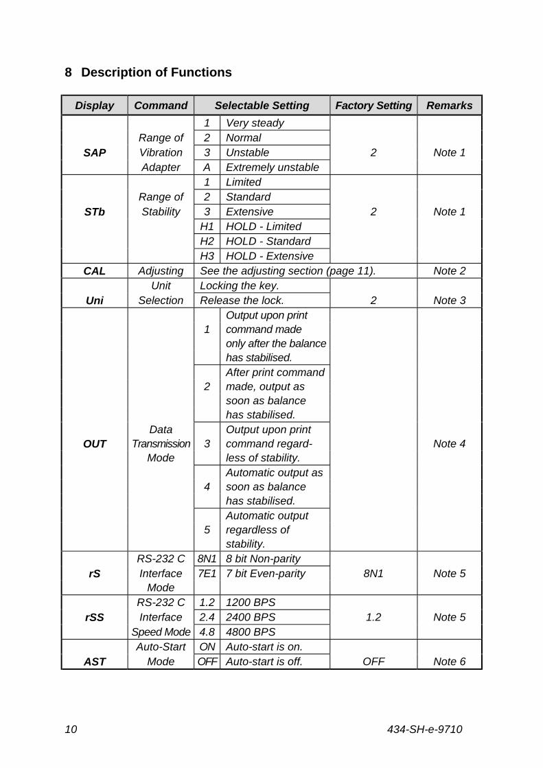
8 Description of Functions
Display Command Selectable Setting Factory Setting Remarks
1 Very steadyRange of 2 Normal
SAP Vibration 3 Unstable 2 Note 1Adapter A Extremely unstable
1 LimitedRange of 2 Standard
STb Stability 3 Extensive 2 Note 1H1 HOLD - LimitedH2 HOLD - StandardH3 HOLD - Extensive
CAL Adjusting See the adjusting section (page 11). Note 2Unit Locking the key.
Uni Selection Release the lock. 2 Note 3Output upon print
1 command madeonly after the balancehas stabilised.After print command
2 made, output assoon as balancehas stabilised.
Data Output upon printOUT Transmission 3 command regard- Note 4
Mode less of stability.Automatic output as
4 soon as balancehas stabilised.Automatic output
5 regardless ofstability.
RS-232 C 8N1 8 bit Non-parityrS Interface 7E1 7 bit Even-parity 8N1 Note 5
ModeRS-232 C 1.2 1200 BPS
rSS Interface 2.4 2400 BPS 1.2 Note 5Speed Mode 4.8 4800 BPSAuto-Start ON Auto-start is on.
AST Mode OFF Auto-start is off. OFF Note 6
434-SH-e-9710 11
9 Weighing Unit Initialisation
9.1 Keyboard Method
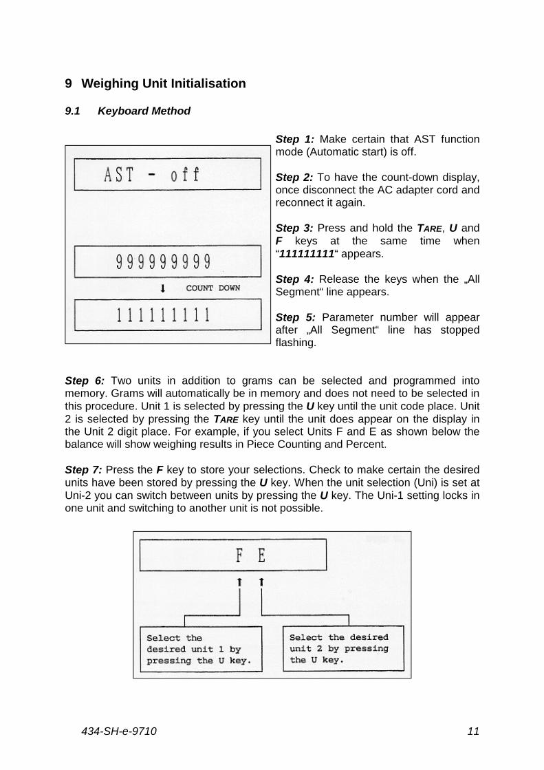
Step 1: Make certain that AST functionmode (Automatic start) is off.
Step 2: To have the count-down display,once disconnect the AC adapter cord andreconnect it again.
Step 3: Press and hold the TARE, U andF keys at the same time when“111111111“ appears.
Step 4: Release the keys when the „AllSegment“ line appears.
Step 5: Parameter number will appearafter „All Segment“ line has stoppedflashing.
Step 6: Two units in addition to grams can be selected and programmed intomemory. Grams will automatically be in memory and does not need to be selected inthis procedure. Unit 1 is selected by pressing the U key until the unit code place. Unit2 is selected by pressing the TARE key until the unit does appear on the display inthe Unit 2 digit place. For example, if you select Units F and E as shown below thebalance will show weighing results in Piece Counting and Percent.
Step 7: Press the F key to store your selections. Check to make certain the desiredunits have been stored by pressing the U key. When the unit selection (Uni) is set atUni-2 you can switch between units by pressing the U key. The Uni-1 setting locks inone unit and switching to another unit is not possible.
434-SH-e-971012
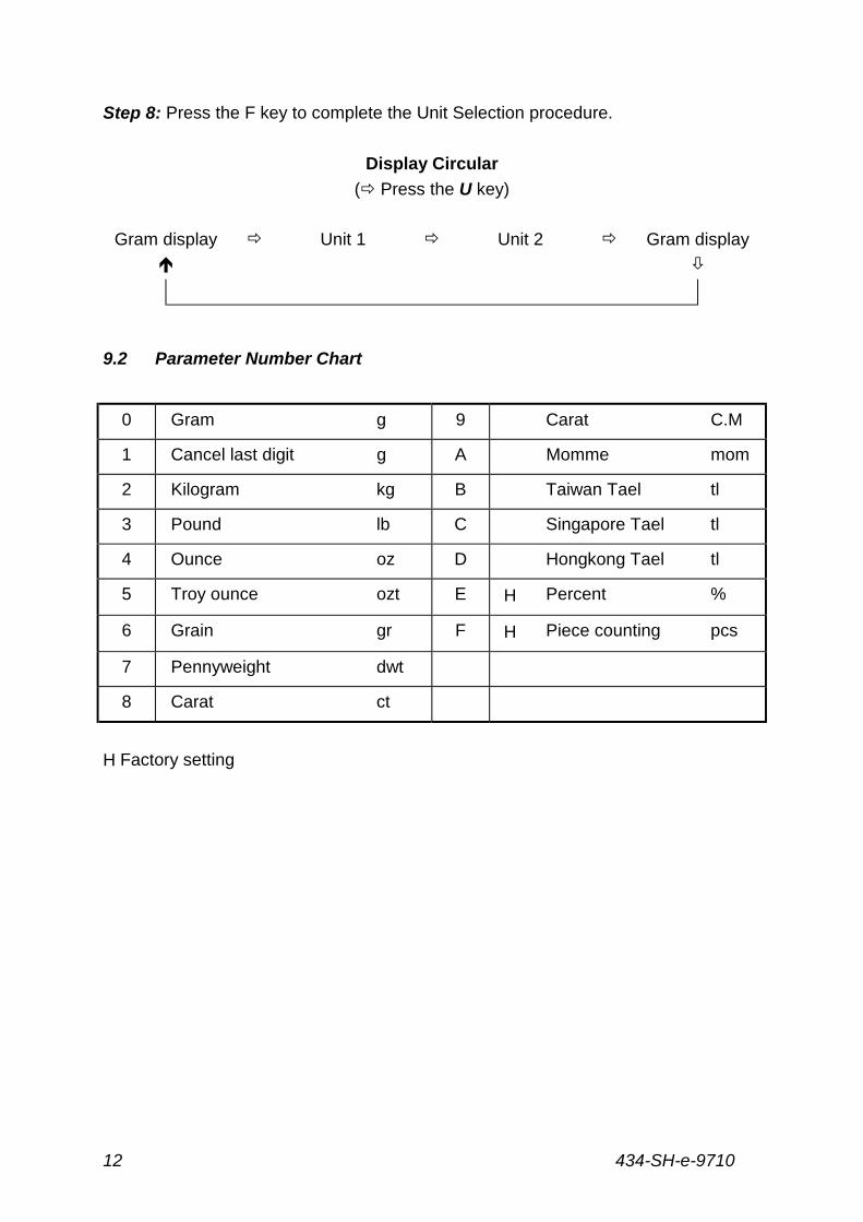
Step 8: Press the F key to complete the Unit Selection procedure.
Display Circular
(# Press the U key)
Gram display # Unit 1 # Unit 2 # Gram display
$ %
9.2 Parameter Number Chart
0 Gram g 9 Carat C.M
1 Cancel last digit g A Momme mom
2 Kilogram kg B Taiwan Tael tl
3 Pound lb C Singapore Tael tl
4 Ounce oz D Hongkong Tael tl
5 Troy ounce ozt E Η Percent %
6 Grain gr F Η Piece counting pcs
7 Pennyweight dwt
8 Carat ct
Η Factory setting
434-SH-e-9710 13
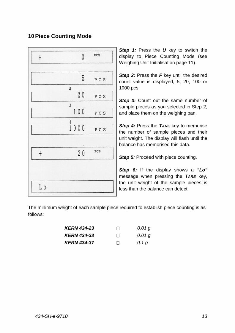
10 Piece Counting Mode
Step 1: Press the U key to switch thedisplay to Piece Counting Mode (seeWeighing Unit Initialisation page 11).
Step 2: Press the F key until the desiredcount value is displayed, 5, 20, 100 or1000 pcs.
Step 3: Count out the same number ofsample pieces as you selected in Step 2,and place them on the weighing pan.
Step 4: Press the TARE key to memorisethe number of sample pieces and theirunit weight. The display will flash until thebalance has memorised this data.
Step 5: Proceed with piece counting.
Step 6: If the display shows a "Lo"message when pressing the TARE key,the unit weight of the sample pieces isless than the balance can detect.
The minimum weight of each sample piece required to establish piece counting is as
follows:
KERN 434-23 ⇑ 0.01 g
KERN 434-33 ⇑ 0.01 g
KERN 434-37 ⇑ 0.1 g
434-SH-e-971014
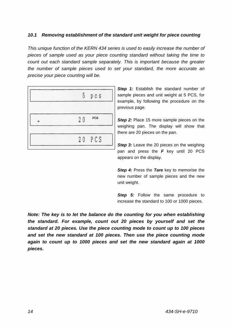
10.1 Removing establishment of the standard unit weight for piece counting
This unique function of the KERN 434 series is used to easily increase the number of
pieces of sample used as your piece counting standard without taking the time to
count out each standard sample separately. This is important because the greater
the number of sample pieces used to set your standard, the more accurate an
precise your piece counting will be.
Step 1: Establish the standard number of
sample pieces and unit weight at 5 PCS, for
example, by following the procedure on the
previous page.
Step 2: Place 15 more sample pieces on the
weighing pan. The display will show that
there are 20 pieces on the pan.
Step 3: Leave the 20 pieces on the weighing
pan and press the F key until 20 PCS
appears on the display.
Step 4: Press the Tare key to memorise the
new number of sample pieces and the new
unit weight.
Step 5: Follow the same procedure to
increase the standard to 100 or 1000 pieces.
Note: The key is to let the balance do the counting for you when establishing
the standard. For example, count out 20 pieces by yourself and set the
standard at 20 pieces. Use the piece counting mode to count up to 100 pieces
and set the new standard at 100 pieces. Then use the piece counting mode
again to count up to 1000 pieces and set the new standard again at 1000
pieces.
434-SH-e-9710 15
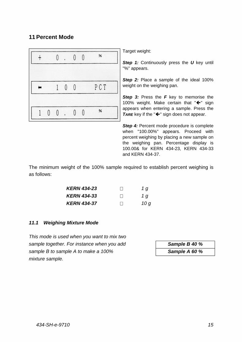
11 Percent Mode
Target weight:
Step 1: Continuously press the U key until"%" appears.
Step 2: Place a sample of the ideal 100%weight on the weighing pan.
Step 3: Press the F key to memorise the100% weight. Make certain that """ signappears when entering a sample. Press theTARE key if the """ sign does not appear.
Step 4: Percent mode procedure is completewhen "100.00%" appears. Proceed withpercent weighing by placing a new sample onthe weighing pan. Percentage display is100.00& for KERN 434-23, KERN 434-33and KERN 434-37.
The minimum weight of the 100% sample required to establish percent weighing is
as follows:
KERN 434-23 ⇑ 1 g
KERN 434-33 ⇑ 1 g
KERN 434-37 ⇑ 10 g
11.1 Weighing Mixture Mode
This mode is used when you want to mix two
sample together. For instance when you add Sample B 40 %
sample B to sample A to make a 100% Sample A 60 %
mixture sample.
434-SH-e-971016
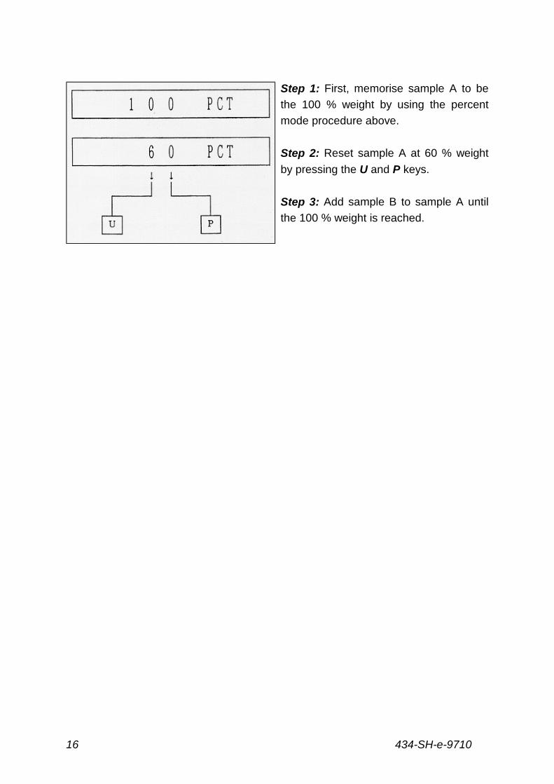
Step 1: First, memorise sample A to be
the 100 % weight by using the percent
mode procedure above.
Step 2: Reset sample A at 60 % weight
by pressing the U and P keys.
Step 3: Add sample B to sample A until
the 100 % weight is reached.
434-SH-e-9710 17
12 Adjusting Introduction
Adjusting of KERN 434 series precision balances is required at initial installation, anytime the balance is moved or bumped, whenever the ambient temperature changesby more than 3° C, and additionally every 30 days or so. Adjusting is necessary fortwo main reasons. First, with time and use, mechanical deviations can occur.Secondly, the weight of a mass in one location or under a certain set of conditionswill not always be the same at a different location or under a different set ofconditions.
There are a number of adjusting procedures that will need to be done during the lifeof a KERN 434 series balance. They are briefly explained below. The actualadjusting procedures are contained throughout this manual (see Table of Contentspage 2).
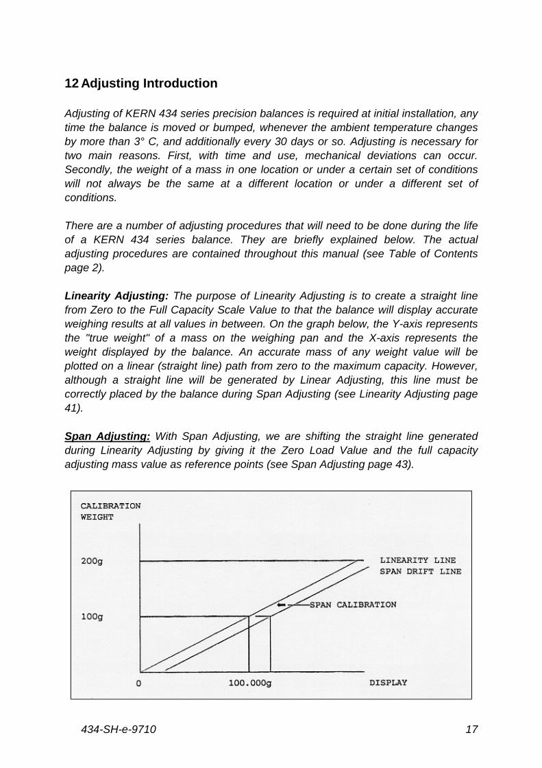
Linearity Adjusting: The purpose of Linearity Adjusting is to create a straight linefrom Zero to the Full Capacity Scale Value to that the balance will display accurateweighing results at all values in between. On the graph below, the Y-axis representsthe "true weight" of a mass on the weighing pan and the X-axis represents theweight displayed by the balance. An accurate mass of any weight value will beplotted on a linear (straight line) path from zero to the maximum capacity. However,although a straight line will be generated by Linear Adjusting, this line must becorrectly placed by the balance during Span Adjusting (see Linearity Adjusting page41).
Span Adjusting: With Span Adjusting, we are shifting the straight line generatedduring Linearity Adjusting by giving it the Zero Load Value and the full capacityadjusting mass value as reference points (see Span Adjusting page 43).

434-SH-e-971018
Temperature Compensation Adjusting: The KERN 434 Mechanical Unit operates
by a force coil moving inside a permanent magnet. A change in ambient temperature
causes a change in the temperature of the Mechanical Unit, in turn altering the
characteristics of the magnet. Unless this is compensated for, it will cause sensitivity
drift problems. KERN 434 balances use a transistor temperature sensor in the
Mechanical Unit to detect changes in temperature. The temperature compensation
settings, which match the temperature characteristics of the Mechanical Unit sensor,
are stored in Electronic Erasable Programmable Read Only Memory (EEPROM).
All KERN 434 series balances undergo a Temperature Compensation Adjusting at
the factory before shipment. At that time all temperature compensations settings are
programmed into EEPROM. Therefore, it is not necessary to perform this adjusting
regularly to avoid sensitivity drift problems.
EEPROM: If the EEPROM is lost due to a component replacement or short circuit, all
adjusting data is cleared. If this happens, the EEPROM must be reinitialised.
Reinitialisations of the EEPROM must always be followed by Linearity and Span
Adjustings. Depending the user’s needs, a Temperature Compensation Adjusting
may also be necessary (see Initialisation of EEPROM, page 39).
434-SH-e-9710 19
13 Inner A /D Counter Check Mode
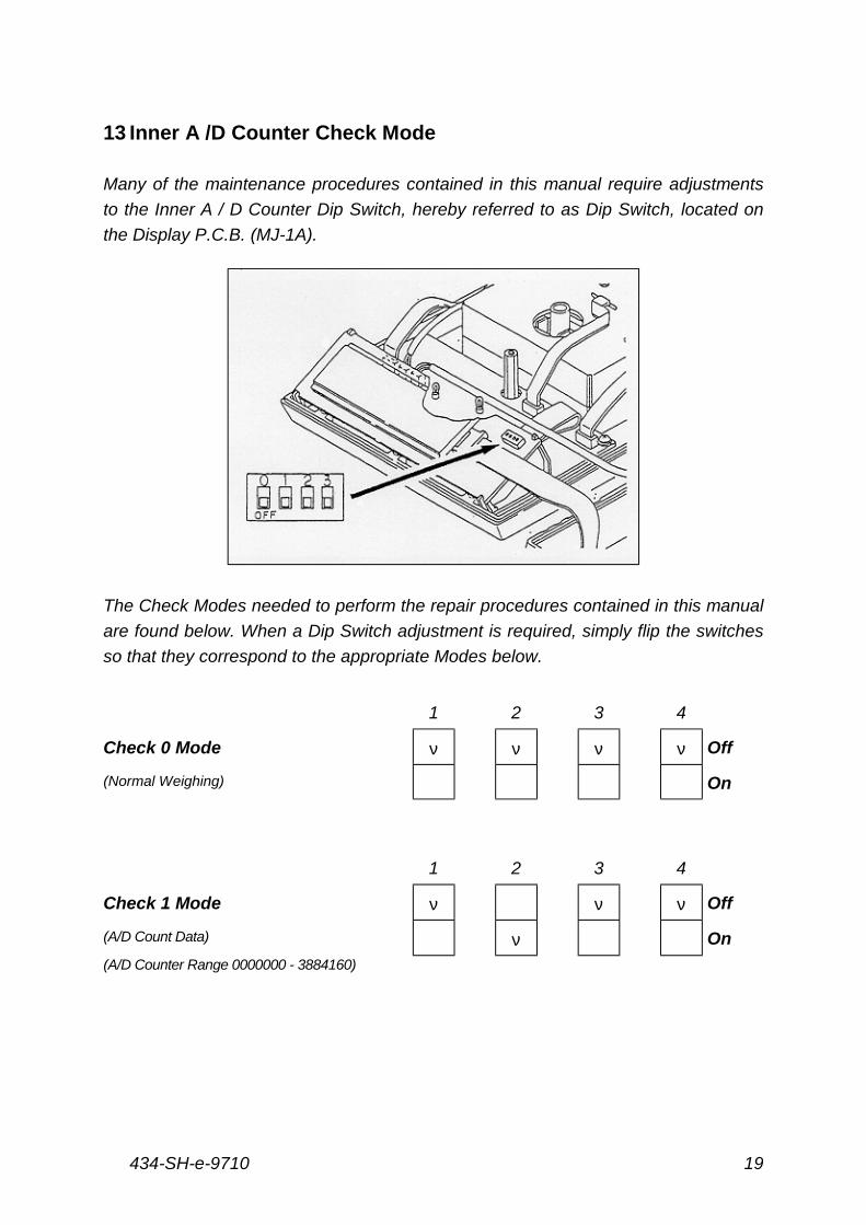
Many of the maintenance procedures contained in this manual require adjustments
to the Inner A / D Counter Dip Switch, hereby referred to as Dip Switch, located on
the Display P.C.B. (MJ-1A).
The Check Modes needed to perform the repair procedures contained in this manual
are found below. When a Dip Switch adjustment is required, simply flip the switches
so that they correspond to the appropriate Modes below.
1 2 3 4
Check 0 Mode ν ν ν ν Off
(Normal Weighing) On
1 2 3 4
Check 1 Mode ν ν ν Off
(A/D Count Data) ν On
(A/D Counter Range 0000000 - 3884160)
434-SH-e-971020
1 2 3 4
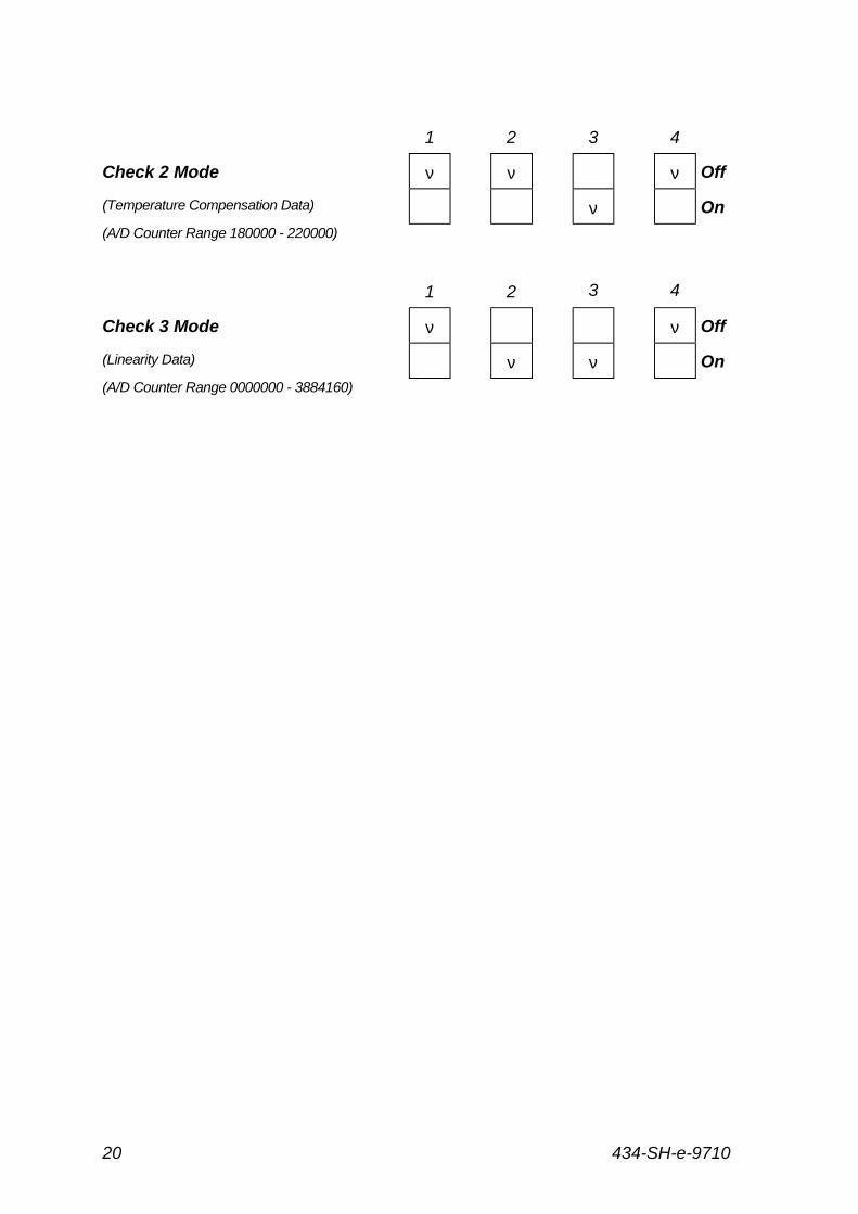
Check 2 Mode ν ν ν Off
(Temperature Compensation Data) ν On
(A/D Counter Range 180000 - 220000)
1 2 3 4
Check 3 Mode ν ν Off
(Linearity Data) ν ν On
(A/D Counter Range 0000000 - 3884160)
434-SH-e-9710 21
14 Disassembly / Assembly
14.1 Removing the Top Case
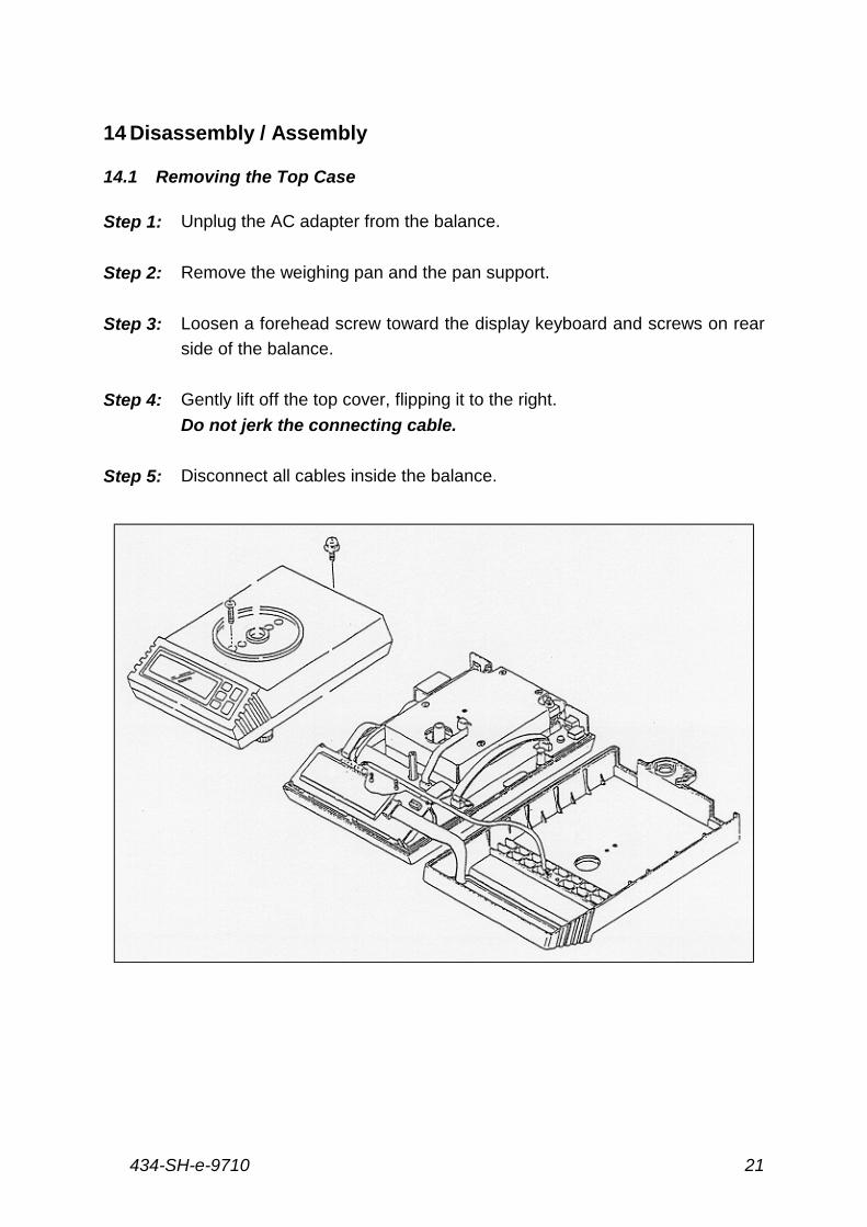
Step 1: Unplug the AC adapter from the balance.
Step 2: Remove the weighing pan and the pan support.
Step 3: Loosen a forehead screw toward the display keyboard and screws on rear
side of the balance.
Step 4: Gently lift off the top cover, flipping it to the right.
Do not jerk the connecting cable.
Step 5: Disconnect all cables inside the balance.
434-SH-e-971022
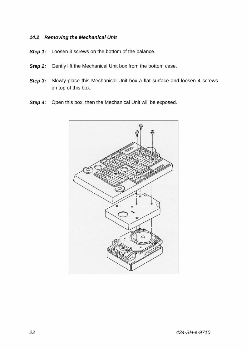
14.2 Removing the Mechanical Unit
Step 1: Loosen 3 screws on the bottom of the balance.
Step 2: Gently lift the Mechanical Unit box from the bottom case.
Step 3: Slowly place this Mechanical Unit box a flat surface and loosen 4 screws
on top of this box.
Step 4: Open this box, then the Mechanical Unit will be exposed.
434-SH-e-9710 23
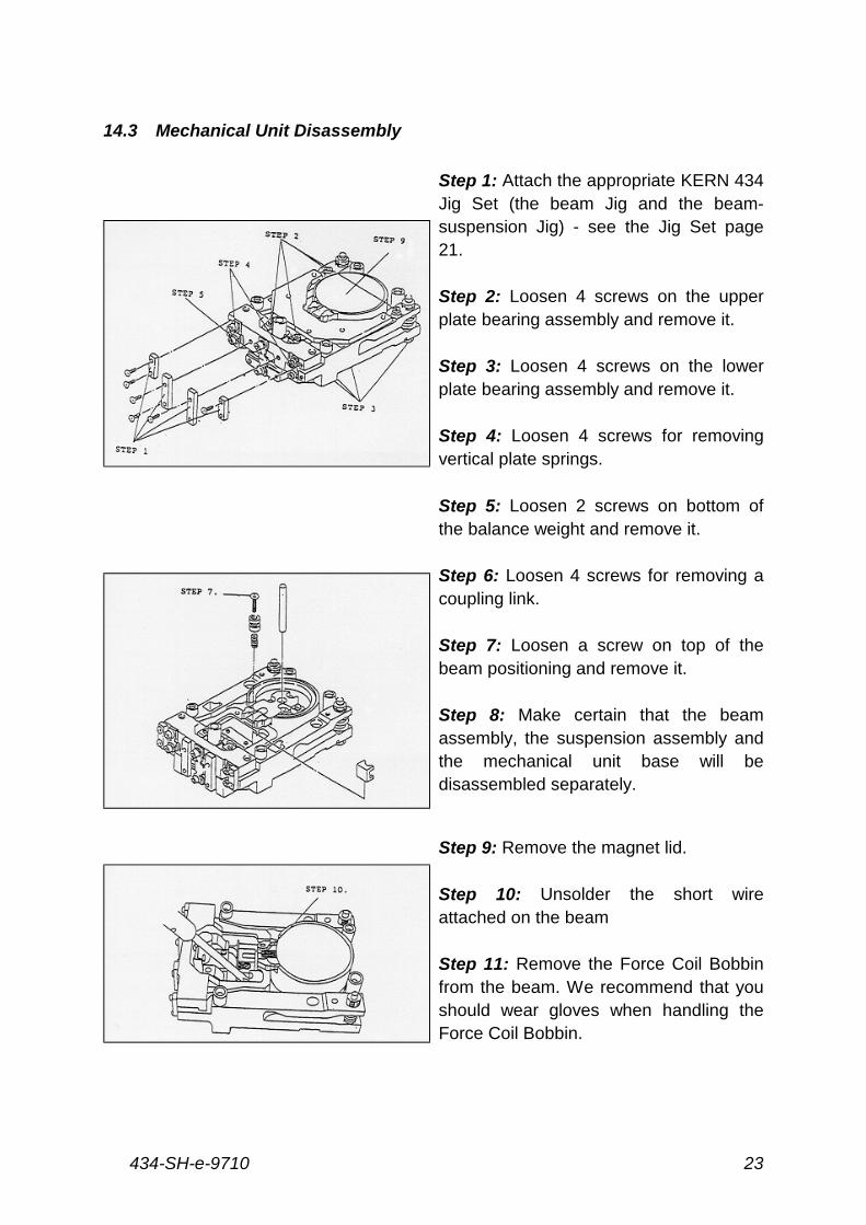
14.3 Mechanical Unit Disassembly
Step 1: Attach the appropriate KERN 434Jig Set (the beam Jig and the beam-suspension Jig) - see the Jig Set page21.
Step 2: Loosen 4 screws on the upperplate bearing assembly and remove it.
Step 3: Loosen 4 screws on the lowerplate bearing assembly and remove it.
Step 4: Loosen 4 screws for removingvertical plate springs.
Step 5: Loosen 2 screws on bottom ofthe balance weight and remove it.
Step 6: Loosen 4 screws for removing acoupling link.
Step 7: Loosen a screw on top of thebeam positioning and remove it.
Step 8: Make certain that the beamassembly, the suspension assembly andthe mechanical unit base will bedisassembled separately.
Step 9: Remove the magnet lid.
Step 10: Unsolder the short wireattached on the beam
Step 11: Remove the Force Coil Bobbinfrom the beam. We recommend that youshould wear gloves when handling theForce Coil Bobbin.
434-SH-e-971024
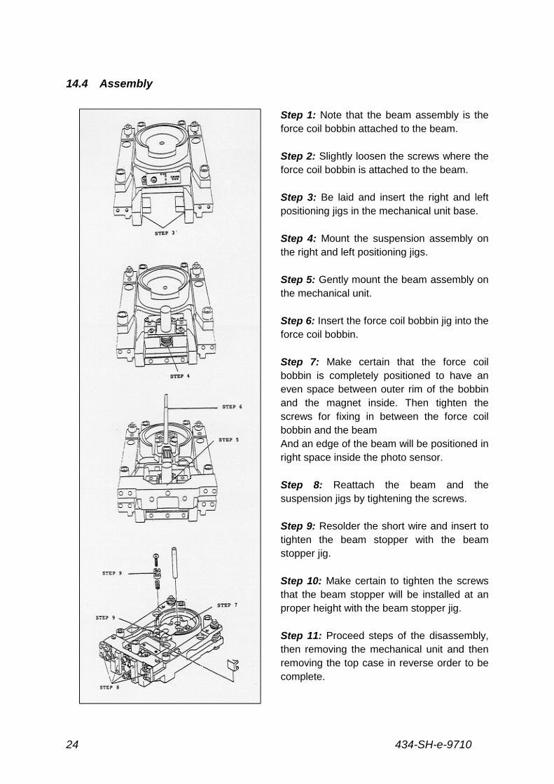
14.4 Assembly
Step 1: Note that the beam assembly is theforce coil bobbin attached to the beam.
Step 2: Slightly loosen the screws where theforce coil bobbin is attached to the beam.
Step 3: Be laid and insert the right and leftpositioning jigs in the mechanical unit base.
Step 4: Mount the suspension assembly onthe right and left positioning jigs.
Step 5: Gently mount the beam assembly onthe mechanical unit.
Step 6: Insert the force coil bobbin jig into theforce coil bobbin.
Step 7: Make certain that the force coilbobbin is completely positioned to have aneven space between outer rim of the bobbinand the magnet inside. Then tighten thescrews for fixing in between the force coilbobbin and the beamAnd an edge of the beam will be positioned inright space inside the photo sensor.
Step 8: Reattach the beam and thesuspension jigs by tightening the screws.
Step 9: Resolder the short wire and insert totighten the beam stopper with the beamstopper jig.
Step 10: Make certain to tighten the screwsthat the beam stopper will be installed at anproper height with the beam stopper jig.
Step 11: Proceed steps of the disassembly,then removing the mechanical unit and thenremoving the top case in reverse order to becomplete.
434-SH-e-9710 25
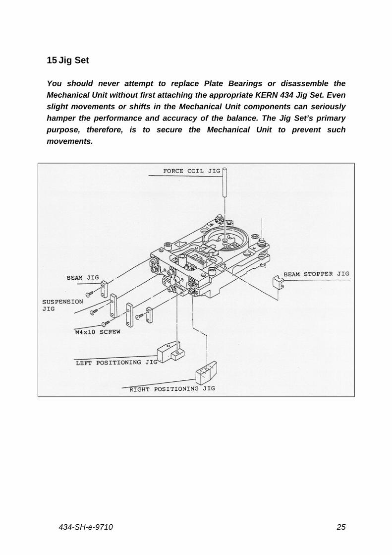
15 Jig Set
You should never attempt to replace Plate Bearings or disassemble the
Mechanical Unit without first attaching the appropriate KERN 434 Jig Set. Even
slight movements or shifts in the Mechanical Unit components can seriously
hamper the performance and accuracy of the balance. The Jig Set’s primary
purpose, therefore, is to secure the Mechanical Unit to prevent such
movements.
434-SH-e-971026
16 Additional Disassembly / Assembly
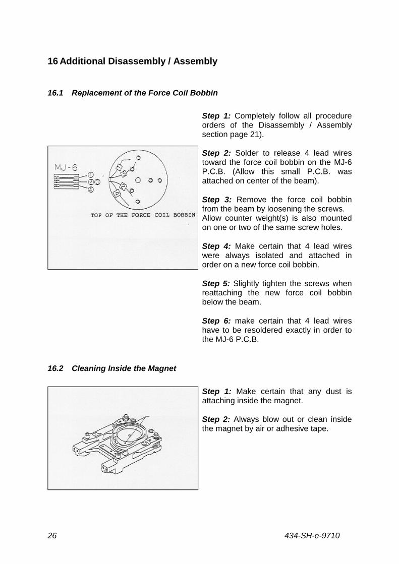
16.1 Replacement of the Force Coil Bobbin
Step 1: Completely follow all procedureorders of the Disassembly / Assemblysection page 21).
Step 2: Solder to release 4 lead wirestoward the force coil bobbin on the MJ-6P.C.B. (Allow this small P.C.B. wasattached on center of the beam).
Step 3: Remove the force coil bobbinfrom the beam by loosening the screws.Allow counter weight(s) is also mountedon one or two of the same screw holes.
Step 4: Make certain that 4 lead wireswere always isolated and attached inorder on a new force coil bobbin.
Step 5: Slightly tighten the screws whenreattaching the new force coil bobbinbelow the beam.
Step 6: make certain that 4 lead wireshave to be resoldered exactly in order tothe MJ-6 P.C.B.
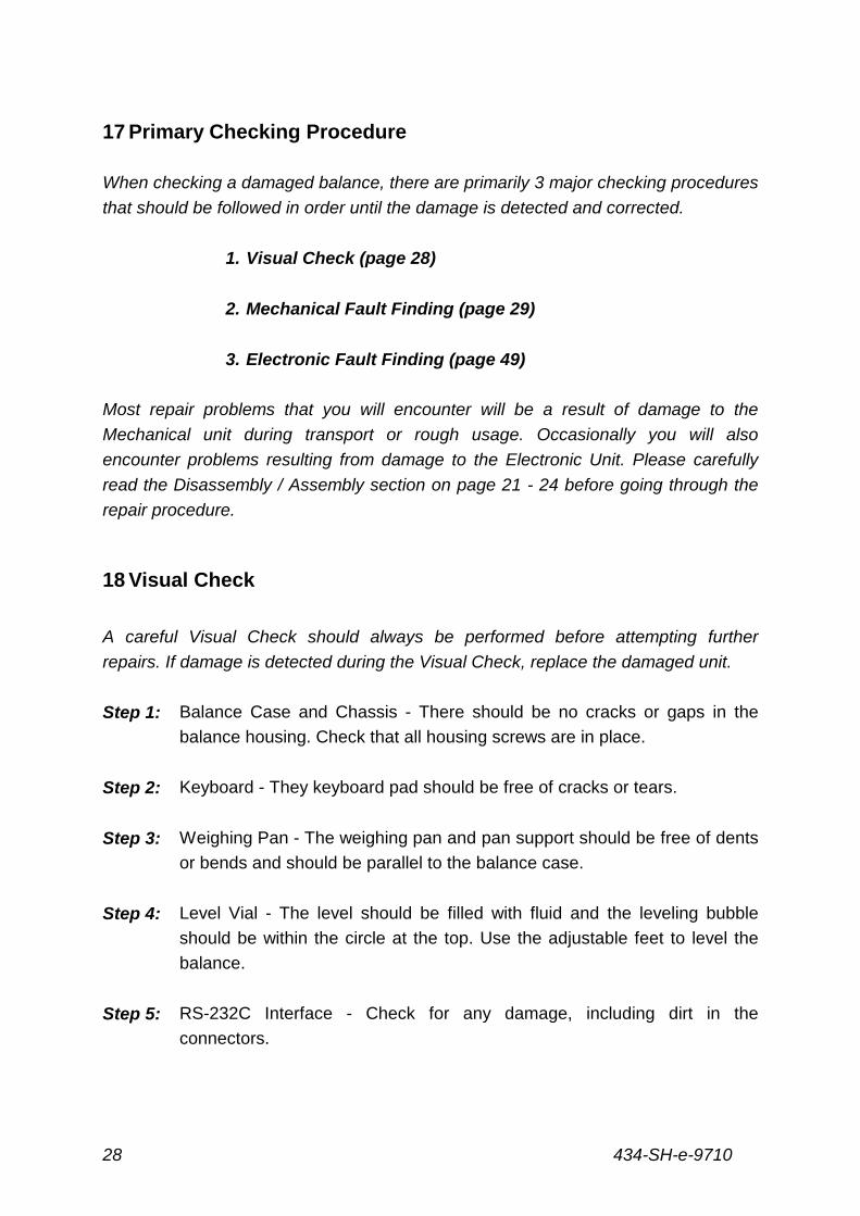
16.2 Cleaning Inside the Magnet
Step 1: Make certain that any dust isattaching inside the magnet.
Step 2: Always blow out or clean insidethe magnet by air or adhesive tape.

434-SH-e-9710 27
16.3 Positioning Edge of the Beam Inside the Photo Sensor
Edge of the have has to be positioned 1
or 1.5 mm space inside the photo sensor.
434-SH-e-971028
17 Primary Checking Procedure
When checking a damaged balance, there are primarily 3 major checking procedures
that should be followed in order until the damage is detected and corrected.
1. Visual Check (page 28)
2. Mechanical Fault Finding (page 29)
3. Electronic Fault Finding (page 49)
Most repair problems that you will encounter will be a result of damage to the
Mechanical unit during transport or rough usage. Occasionally you will also
encounter problems resulting from damage to the Electronic Unit. Please carefully
read the Disassembly / Assembly section on page 21 - 24 before going through the
repair procedure.
18 Visual Check
A careful Visual Check should always be performed before attempting further
repairs. If damage is detected during the Visual Check, replace the damaged unit.
Step 1: Balance Case and Chassis - There should be no cracks or gaps in the
balance housing. Check that all housing screws are in place.
Step 2: Keyboard - They keyboard pad should be free of cracks or tears.
Step 3: Weighing Pan - The weighing pan and pan support should be free of dents
or bends and should be parallel to the balance case.
Step 4: Level Vial - The level should be filled with fluid and the leveling bubble
should be within the circle at the top. Use the adjustable feet to level the
balance.
Step 5: RS-232C Interface - Check for any damage, including dirt in the
connectors.
434-SH-e-9710 29
19 Mechanical Fault Finding
This section provides a simple fault finding method when checking a balance
for Mechanical Unit damage. When mechanical damage is present, there are
two major problems that can occur when the power switch is turned on. First,
the display may show only a decimal point with a polarity sign (+ / -), "all
segment lines" message or no display at all. The second problem is when the
display shows and unstable weighing result.
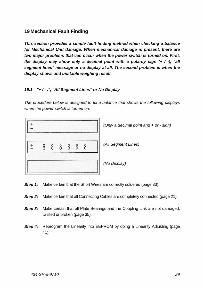
19.1 "+ / - .", "All Segment Lines" or No Display
The procedure below is designed to fix a balance that shows the following displays
when the power switch is turned on.
(Only a decimal point and + or - sign)
(All Segment Lines)
(No Display)
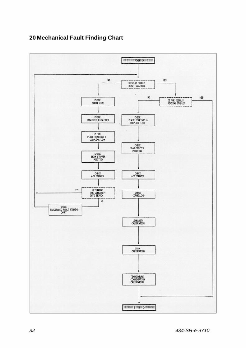
Step 1: Make certain that the Short Wires are correctly soldered (page 33).
Step 2: Make certain that all Connecting Cables are completely connected (page 21).
Step 3: Make certain that all Plate Bearings and the Coupling Link are not damaged,
twisted or broken (page 35).
Step 4: Reprogram the Linearity into EEPROM by doing a Linearity Adjusting (page
41).
434-SH-e-971030
Step 5: Return to the normal weighing mode by setting Dip Switch 2 to Check 0 Mode,
and make certain that the three error messages above are gone and that the
balance shows a correct weighing display. If not, check all circuit boards.
Step 6: If the display shows an unstable weighing result, proceed to the Unstable
Weighing Results Adjustment procedure on page 30.
Step 7: If the display shows a stable weighing reading, the problem has been
corrected. Do a Span Adjusting (page 43) before beginning to weigh.
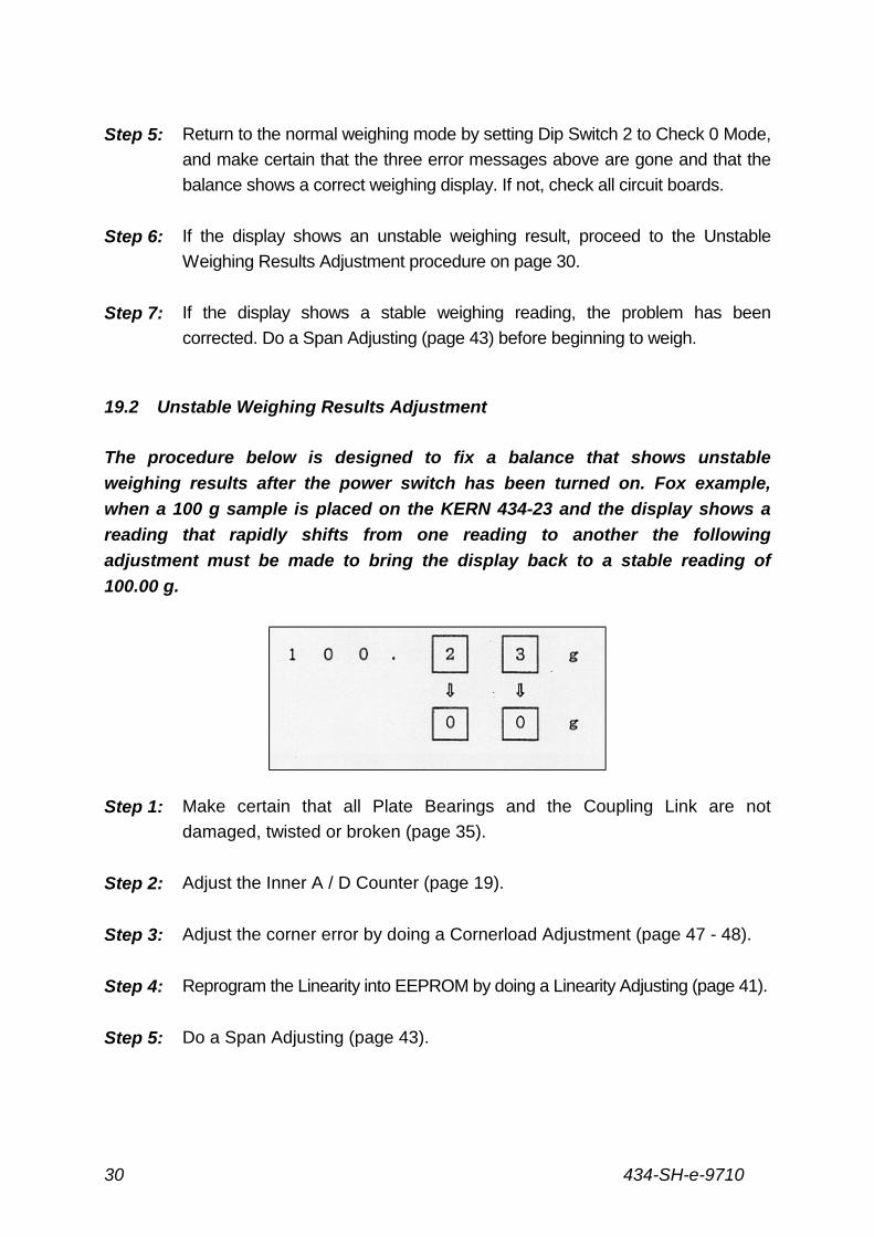
19.2 Unstable Weighing Results Adjustment
The procedure below is designed to fix a balance that shows unstable
weighing results after the power switch has been turned on. Fox example,
when a 100 g sample is placed on the KERN 434-23 and the display shows a
reading that rapidly shifts from one reading to another the following
adjustment must be made to bring the display back to a stable reading of
100.00 g.
Step 1: Make certain that all Plate Bearings and the Coupling Link are not
damaged, twisted or broken (page 35).
Step 2: Adjust the Inner A / D Counter (page 19).
Step 3: Adjust the corner error by doing a Cornerload Adjustment (page 47 - 48).
Step 4: Reprogram the Linearity into EEPROM by doing a Linearity Adjusting (page 41).
Step 5: Do a Span Adjusting (page 43).

434-SH-e-9710 31
Step 6: If the problem has been corrected, the balance will display a "Pass"
message. If a "Pass" message does not appear, check all circuit boards.
434-SH-e-971032
20 Mechanical Fault Finding Chart
434-SH-e-9710 33
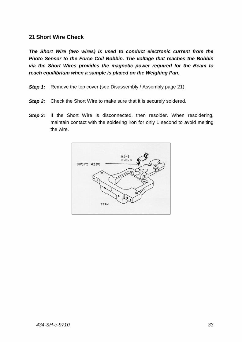
21 Short Wire Check
The Short Wire (two wires) is used to conduct electronic current from the
Photo Sensor to the Force Coil Bobbin. The voltage that reaches the Bobbin
via the Short Wires provides the magnetic power required for the Beam to
reach equilibrium when a sample is placed on the Weighing Pan.
Step 1: Remove the top cover (see Disassembly / Assembly page 21).
Step 2: Check the Short Wire to make sure that it is securely soldered.
Step 3: If the Short Wire is disconnected, then resolder. When resoldering,
maintain contact with the soldering iron for only 1 second to avoid melting
the wire.
434-SH-e-971034
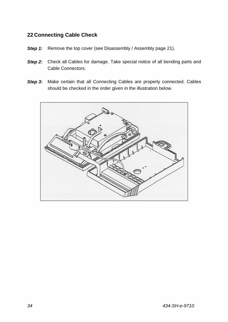
22 Connecting Cable Check
Step 1: Remove the top cover (see Disassembly / Assembly page 21).
Step 2: Check all Cables for damage. Take special notice of all bending parts and
Cable Connectors.
Step 3: Make certain that all Connecting Cables are properly connected. Cables
should be checked in the order given in the illustration below.
434-SH-e-9710 35
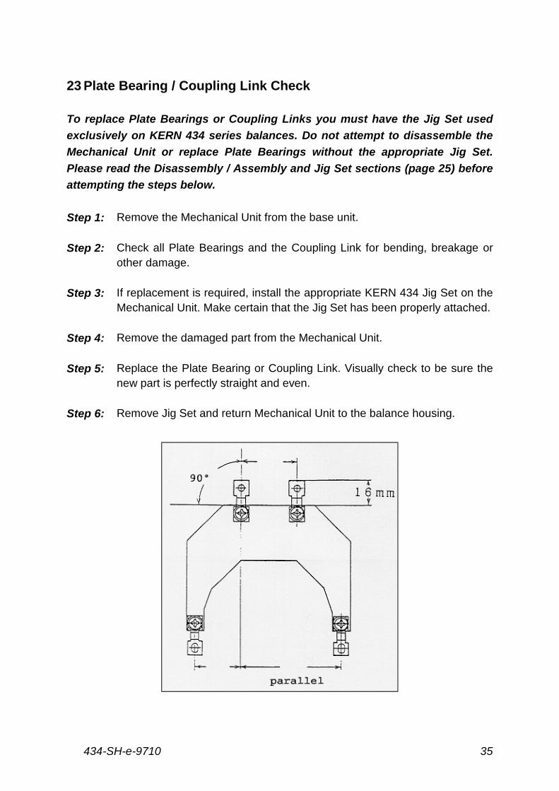
23 Plate Bearing / Coupling Link Check
To replace Plate Bearings or Coupling Links you must have the Jig Set used
exclusively on KERN 434 series balances. Do not attempt to disassemble the
Mechanical Unit or replace Plate Bearings without the appropriate Jig Set.
Please read the Disassembly / Assembly and Jig Set sections (page 25) before
attempting the steps below.
Step 1: Remove the Mechanical Unit from the base unit.
Step 2: Check all Plate Bearings and the Coupling Link for bending, breakage orother damage.
Step 3: If replacement is required, install the appropriate KERN 434 Jig Set on theMechanical Unit. Make certain that the Jig Set has been properly attached.
Step 4: Remove the damaged part from the Mechanical Unit.
Step 5: Replace the Plate Bearing or Coupling Link. Visually check to be sure thenew part is perfectly straight and even.
Step 6: Remove Jig Set and return Mechanical Unit to the balance housing.
434-SH-e-971036
Remark: When reattaching plate bearing(s), then your tightening torgue has to be
exactly the same compared to other tightening torgues.
KERN 434-23, 434-33 1 Nm (10 kgfcm)
KERN 434-37 1.8 Nm (18 kgfcm)
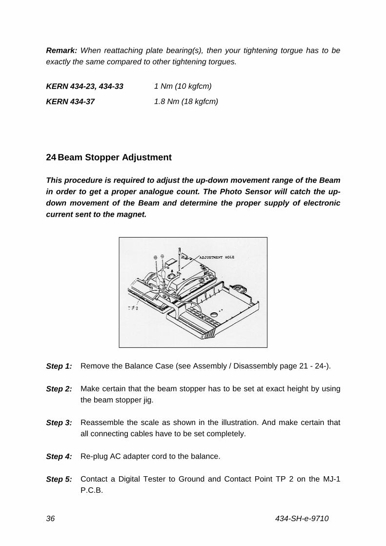
24 Beam Stopper Adjustment
This procedure is required to adjust the up-down movement range of the Beam
in order to get a proper analogue count. The Photo Sensor will catch the up-
down movement of the Beam and determine the proper supply of electronic
current sent to the magnet.
Step 1: Remove the Balance Case (see Assembly / Disassembly page 21 - 24-).
Step 2: Make certain that the beam stopper has to be set at exact height by using
the beam stopper jig.
Step 3: Reassemble the scale as shown in the illustration. And make certain that
all connecting cables have to be set completely.
Step 4: Re-plug AC adapter cord to the balance.
Step 5: Contact a Digital Tester to Ground and Contact Point TP 2 on the MJ-1
P.C.B.
434-SH-e-9710 37
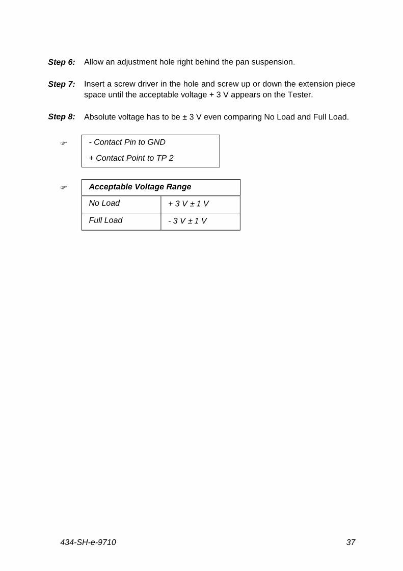
Step 6: Allow an adjustment hole right behind the pan suspension.
Step 7: Insert a screw driver in the hole and screw up or down the extension piecespace until the acceptable voltage + 3 V appears on the Tester.
Step 8: Absolute voltage has to be ± 3 V even comparing No Load and Full Load.
& - Contact Pin to GND
+ Contact Point to TP 2
& Acceptable Voltage Range
No Load + 3 V ± 1 V
Full Load - 3 V ± 1 V
434-SH-e-971038
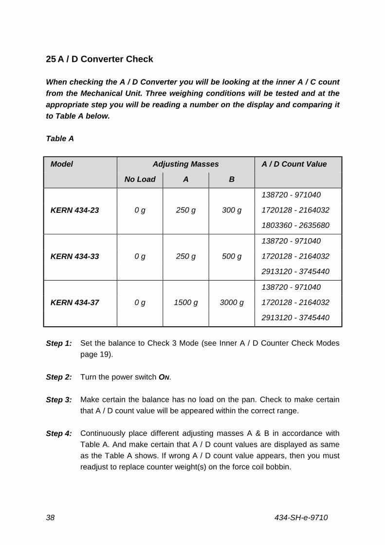
25 A / D Converter Check
When checking the A / D Converter you will be looking at the inner A / C count
from the Mechanical Unit. Three weighing conditions will be tested and at the
appropriate step you will be reading a number on the display and comparing it
to Table A below.
Table A
Model Adjusting Masses A / D Count Value
No Load A B
138720 - 971040
KERN 434-23 0 g 250 g 300 g 1720128 - 2164032
1803360 - 2635680
138720 - 971040
KERN 434-33 0 g 250 g 500 g 1720128 - 2164032
2913120 - 3745440
138720 - 971040
KERN 434-37 0 g 1500 g 3000 g 1720128 - 2164032
2913120 - 3745440
Step 1: Set the balance to Check 3 Mode (see Inner A / D Counter Check Modes
page 19).
Step 2: Turn the power switch ON.
Step 3: Make certain the balance has no load on the pan. Check to make certain
that A / D count value will be appeared within the correct range.
Step 4: Continuously place different adjusting masses A & B in accordance with
Table A. And make certain that A / D count values are displayed as same
as the Table A shows. If wrong A / D count value appears, then you must
readjust to replace counter weight(s) on the force coil bobbin.
434-SH-e-9710 39
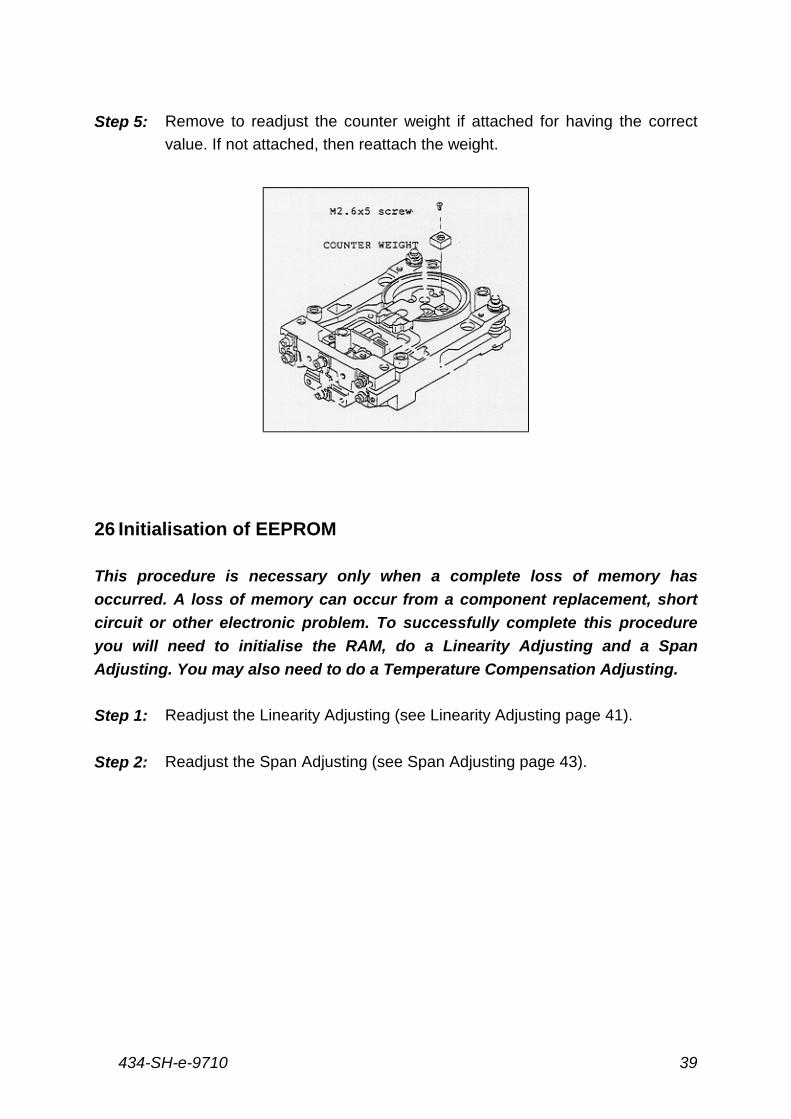
Step 5: Remove to readjust the counter weight if attached for having the correct
value. If not attached, then reattach the weight.
26 Initialisation of EEPROM
This procedure is necessary only when a complete loss of memory has
occurred. A loss of memory can occur from a component replacement, short
circuit or other electronic problem. To successfully complete this procedure
you will need to initialise the RAM, do a Linearity Adjusting and a Span
Adjusting. You may also need to do a Temperature Compensation Adjusting.
Step 1: Readjust the Linearity Adjusting (see Linearity Adjusting page 41).
Step 2: Readjust the Span Adjusting (see Span Adjusting page 43).
434-SH-e-971040
27 Linearity Adjusting
The purpose of Linearity Adjusting is to create a straight line from Zero to the
Full Capacity Scale Value so that the balance will display accurate weighing
results at all values in between. For this adjusting procedure, please use a
high quality, non-magnetic-metric, stainless steel „Standard Mass“ that is
OIML Class F2 or better. Whenever Linearity Adjusting is performed on the
balance, it must be followed by a Span Adjusting.
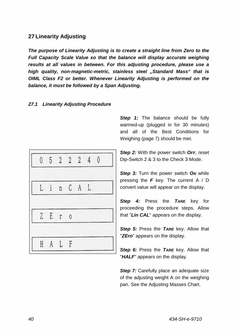
27.1 Linearity Adjusting Procedure
Step 1: The balance should be fully
warmed-up (plugged in for 30 minutes)
and all of the Best Conditions for
Weighing (page 7) should be met.
Step 2: With the power switch OFF, reset
Dip-Switch 2 & 3 to the Check 3 Mode.
Step 3: Turn the power switch ON while
pressing the F key. The current A / D
convert value will appear on the display.
Step 4: Press the TARE key for
proceeding the procedure steps. Allow
that "Lin CAL" appears on the display.
Step 5: Press the TARE key. Allow that
"ZEro" appears on the display.
Step 6: Press the TARE key. Allow that
"HALF" appears on the display.
Step 7: Carefully place an adequate size
of the adjusting weight A on the weighing
pan. See the Adjusting Masses Chart.
434-SH-e-9710 41
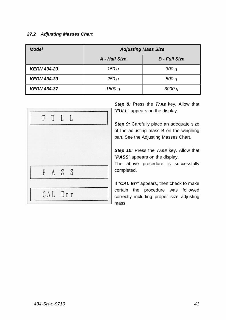
27.2 Adjusting Masses Chart
Model Adjusting Mass Size
A - Half Size B - Full Size
KERN 434-23 150 g 300 g
KERN 434-33 250 g 500 g
KERN 434-37 1500 g 3000 g
Step 8: Press the TARE key. Allow that
"FULL" appears on the display.
Step 9: Carefully place an adequate size
of the adjusting mass B on the weighing
pan. See the Adjusting Masses Chart.
Step 10: Press the TARE key. Allow that
"PASS" appears on the display.
The above procedure is successfully
completed.
If "CAL Err" appears, then check to make
certain the procedure was followed
correctly including proper size adjusting
mass.
434-SH-e-971042
28 Span Adjusting
The balance should be adjusted for span when it is first installed, any time it is
moved or bumped, whenever the ambient temperature changes by more than
3° C, and additionally every 30 days or so. For this adjusting procedure, please
use a high quality, non-magnetic, metric, stainless steel "Standard Mass" that
is OIML Class F2 or better.
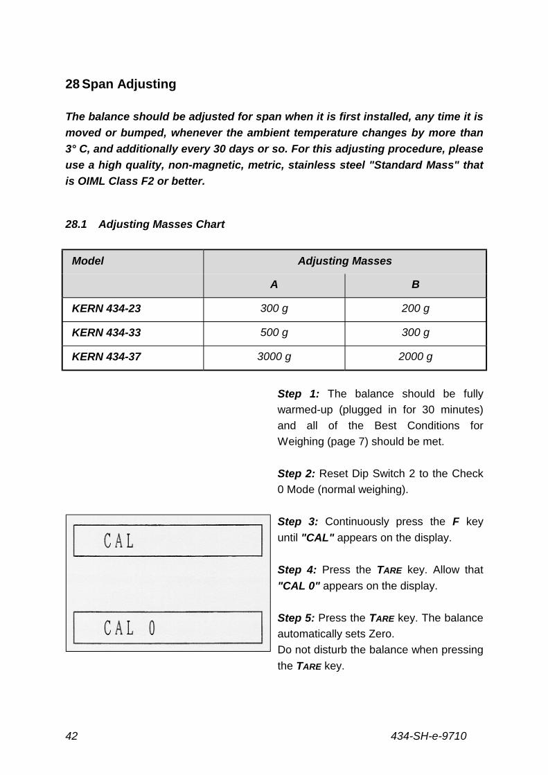
28.1 Adjusting Masses Chart
Model Adjusting Masses
A B
KERN 434-23 300 g 200 g
KERN 434-33 500 g 300 g
KERN 434-37 3000 g 2000 g
Step 1: The balance should be fully
warmed-up (plugged in for 30 minutes)
and all of the Best Conditions for
Weighing (page 7) should be met.
Step 2: Reset Dip Switch 2 to the Check
0 Mode (normal weighing).
Step 3: Continuously press the F key
until "CAL" appears on the display.
Step 4: Press the TARE key. Allow that
"CAL 0" appears on the display.
Step 5: Press the TARE key. The balance
automatically sets Zero.
Do not disturb the balance when pressing
the TARE key.
434-SH-e-9710 43
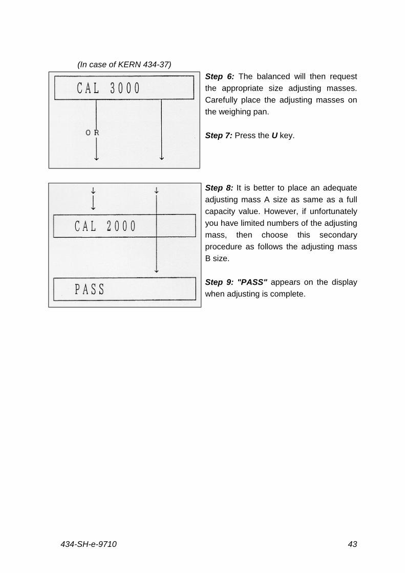
(In case of KERN 434-37)
Step 6: The balanced will then request
the appropriate size adjusting masses.
Carefully place the adjusting masses on
the weighing pan.
Step 7: Press the U key.
Step 8: It is better to place an adequate
adjusting mass A size as same as a full
capacity value. However, if unfortunately
you have limited numbers of the adjusting
mass, then choose this secondary
procedure as follows the adjusting mass
B size.
Step 9: "PASS" appears on the display
when adjusting is complete.
434-SH-e-971044
28.2 Adjusting Mass Tolerance Collection
If users desire to request for you to readjust KERN 434 balances by standard
masses, it is common to know that Standard Masses have always been
certified with an exact tolerance by your local Measurement Authority, then
readjust the span of the KERN 434 balances with this exact tolerance as
follows the below additional procedures.
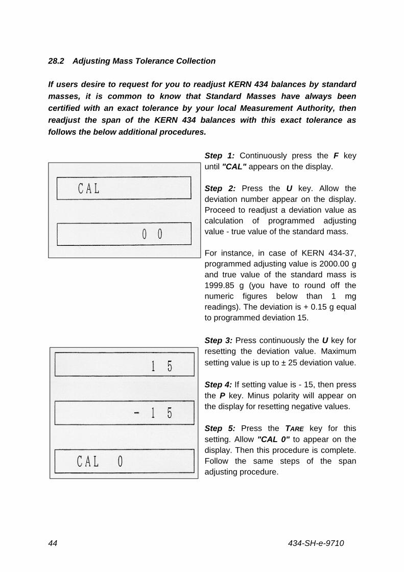
Step 1: Continuously press the F keyuntil "CAL" appears on the display.
Step 2: Press the U key. Allow thedeviation number appear on the display.Proceed to readjust a deviation value ascalculation of programmed adjustingvalue - true value of the standard mass.
For instance, in case of KERN 434-37,programmed adjusting value is 2000.00 gand true value of the standard mass is1999.85 g (you have to round off thenumeric figures below than 1 mgreadings). The deviation is + 0.15 g equalto programmed deviation 15.
Step 3: Press continuously the U key forresetting the deviation value. Maximum
setting value is up to ± 25 deviation value.
Step 4: If setting value is - 15, then pressthe P key. Minus polarity will appear onthe display for resetting negative values.
Step 5: Press the TARE key for thissetting. Allow "CAL 0" to appear on thedisplay. Then this procedure is complete.Follow the same steps of the spanadjusting procedure.
434-SH-e-9710 45
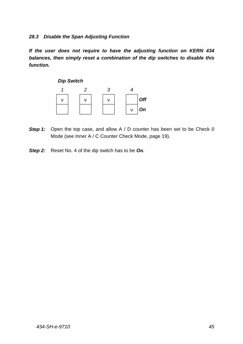
28.3 Disable the Span Adjusting Function
If the user does not require to have the adjusting function on KERN 434
balances, then simply reset a combination of the dip switches to disable this
function.
Dip Switch
1 2 3 4
ν ν ν Off
ν On
Step 1: Open the top case, and allow A / D counter has been set to be Check 0
Mode (see Inner A / C Counter Check Mode, page 19).
Step 2: Reset No. 4 of the dip switch has to be ON.
434-SH-e-971046
29 Cornerload Adjustment
Since the weighing pan is connected to the balance through one central point,
as you move away from the centre toward the outer rim of the pan, mechanical
distortions can occur, thus reducing the balance’s accuracy. Cornerload
Adjustment is performed to compensate for the problem.
Step 1: The balance must be fully warmed-up (plugged in for 30 minutes) before
starting.
Step 2: Remove the top case (see Disassembly / Assembly page 21 - 24).
Step 3: Replace the weighing pan.
Step 4: Make certain that the balance is level.
Step 5: Plug the AC adapter into the power source.
Step 6: Press the ON/OFF key to get a normal weighing display (Check 0 Mode).
Step 7: Place the appropriate Cornerload Adjustment Mass in the centre of the
weighing pan (Point '). Place it around the pan. When using the draft
shield, make certain that it does not touch the pan.
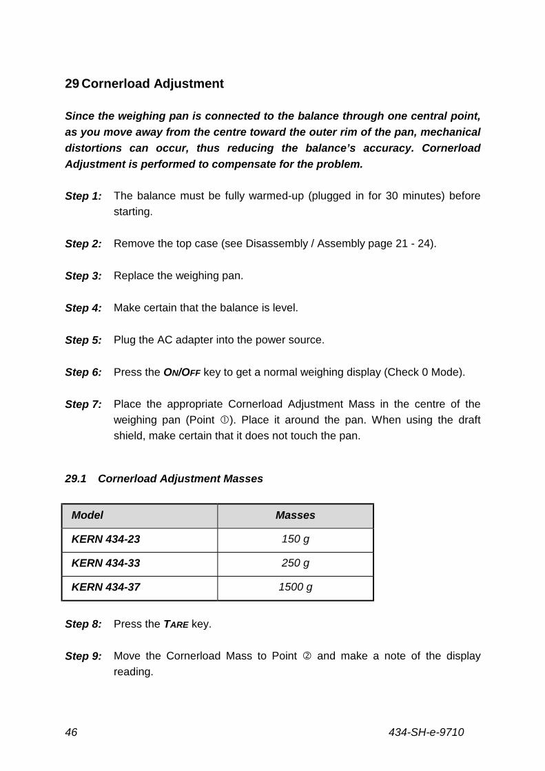
29.1 Cornerload Adjustment Masses
Model Masses
KERN 434-23 150 g
KERN 434-33 250 g
KERN 434-37 1500 g
Step 8: Press the TARE key.
Step 9: Move the Cornerload Mass to Point ( and make a note of the display
reading.
434-SH-e-9710 47
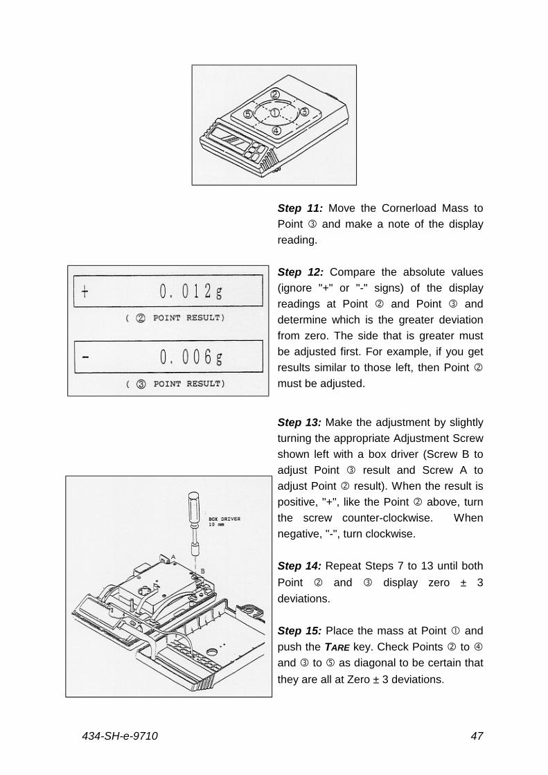
Step 11: Move the Cornerload Mass to
Point ) and make a note of the display
reading.
Step 12: Compare the absolute values
(ignore "+" or "-" signs) of the display
readings at Point ( and Point ) and
determine which is the greater deviation
from zero. The side that is greater must
be adjusted first. For example, if you get
results similar to those left, then Point (
must be adjusted.
Step 13: Make the adjustment by slightly
turning the appropriate Adjustment Screw
shown left with a box driver (Screw B to
adjust Point ) result and Screw A to
adjust Point ( result). When the result is
positive, "+", like the Point ( above, turn
the screw counter-clockwise. When
negative, "-", turn clockwise.
Step 14: Repeat Steps 7 to 13 until both
Point ( and ) display zero ± 3
deviations.
Step 15: Place the mass at Point ' and
push the TARE key. Check Points ( to *
and ) to + as diagonal to be certain that
they are all at Zero ± 3 deviations.
434-SH-e-971048
30 Electronic Fault Finding
The following procedures are used to detect and repair damage to the
Electronic Unit. Before proceeding with any of the repair procedures below, it
is advisable to make a thorough visual check of the Electronic Unit. Look for
dirt or other foreign objects throughout the balance. Check for objects
touching the circuitry, broken circuit paths, grounding, solder dry joints or any
other damage to the P.C. Boards.
30.1 Power Check
Fuse: If the fuse (0.5 AMP) keeps blowing, there is a short circuit. Check the circuitry
for touching objects. Also check the power supply electronics.
AD Adapter: The proper voltage AC adapter for your local power supply is provided
before shipment. If you find that the AC adapter is providing too little voltage or that it
generates irregular heat, check the attached voltage label to make sure the proper
voltage for your local power.
30.2 EEPROM Check
If the EEPROM (Electronic Erasable Programmable Read Only Memory) has
been lost, the balance will not show the normal weighing display when the
power switch is turned on. One of the following three messages will appear:
434-SH-e-9710 49
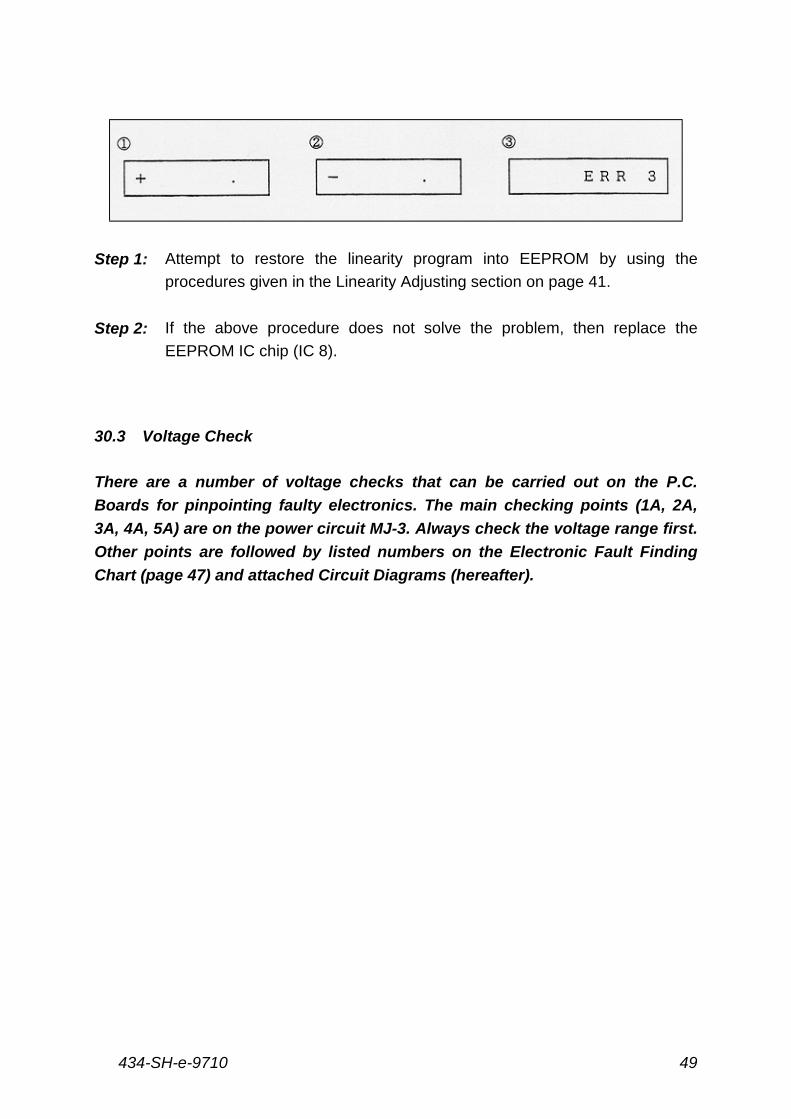
Step 1: Attempt to restore the linearity program into EEPROM by using the
procedures given in the Linearity Adjusting section on page 41.
Step 2: If the above procedure does not solve the problem, then replace the
EEPROM IC chip (IC 8).
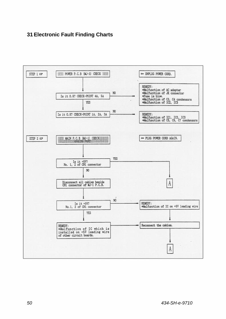
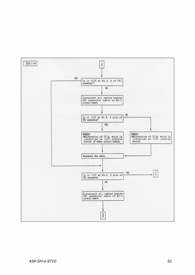
30.3 Voltage Check
There are a number of voltage checks that can be carried out on the P.C.
Boards for pinpointing faulty electronics. The main checking points (1A, 2A,
3A, 4A, 5A) are on the power circuit MJ-3. Always check the voltage range first.
Other points are followed by listed numbers on the Electronic Fault Finding
Chart (page 47) and attached Circuit Diagrams (hereafter).
434-SH-e-971050
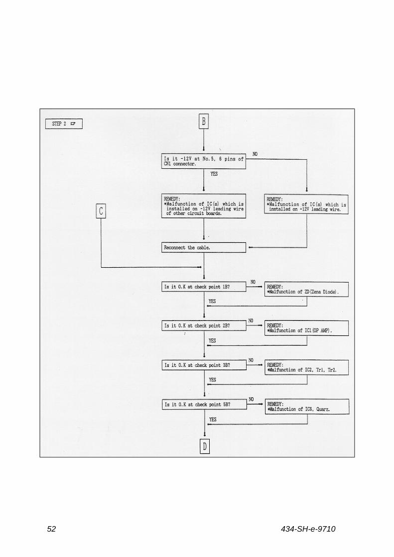
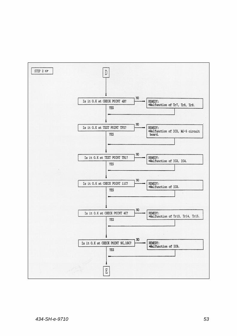
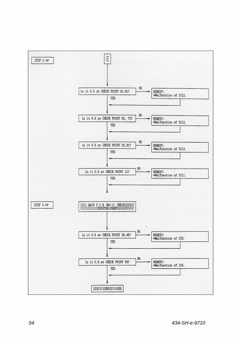
31 Electronic Fault Finding Charts
434-SH-e-9710 51
434-SH-e-971052
434-SH-e-9710 53
434-SH-e-971054
434-SH-e-9710 55
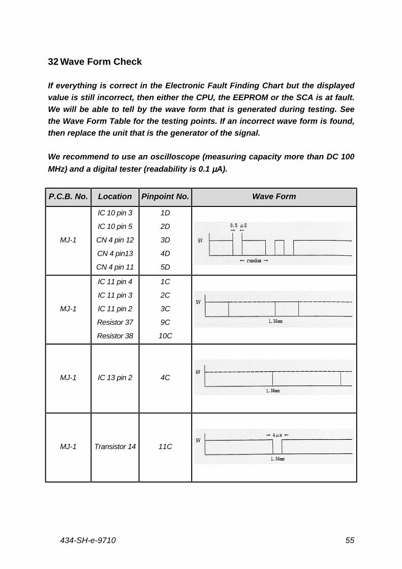
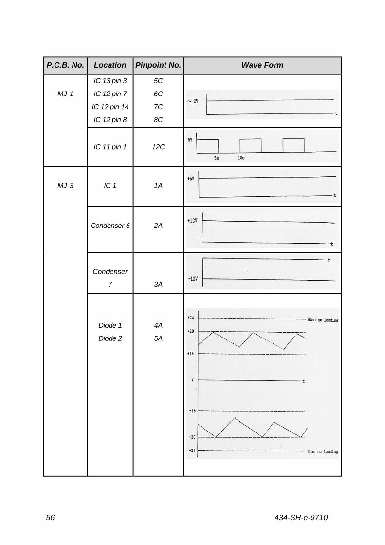
32 Wave Form Check
If everything is correct in the Electronic Fault Finding Chart but the displayed
value is still incorrect, then either the CPU, the EEPROM or the SCA is at fault.
We will be able to tell by the wave form that is generated during testing. See
the Wave Form Table for the testing points. If an incorrect wave form is found,
then replace the unit that is the generator of the signal.
We recommend to use an oscilloscope (measuring capacity more than DC 100
MHz) and a digital tester (readability is 0.1 µµµµA).
P.C.B. No. Location Pinpoint No. Wave Form
MJ-1
IC 10 pin 3
IC 10 pin 5
CN 4 pin 12
CN 4 pin13
CN 4 pin 11
1D
2D
3D
4D
5D
MJ-1
IC 11 pin 4
IC 11 pin 3
IC 11 pin 2
Resistor 37
Resistor 38
1C
2C
3C
9C
10C
MJ-1 IC 13 pin 2 4C
MJ-1 Transistor 14 11C
434-SH-e-971056
P.C.B. No. Location Pinpoint No. Wave Form
MJ-1
IC 13 pin 3
IC 12 pin 7
IC 12 pin 14
IC 12 pin 8
5C
6C
7C
8C
IC 11 pin 1 12C
MJ-3 IC 1 1A
Condenser 6 2A
Condenser
7 3A
Diode 1
Diode 2
4A
5A
434-SH-e-9710 57
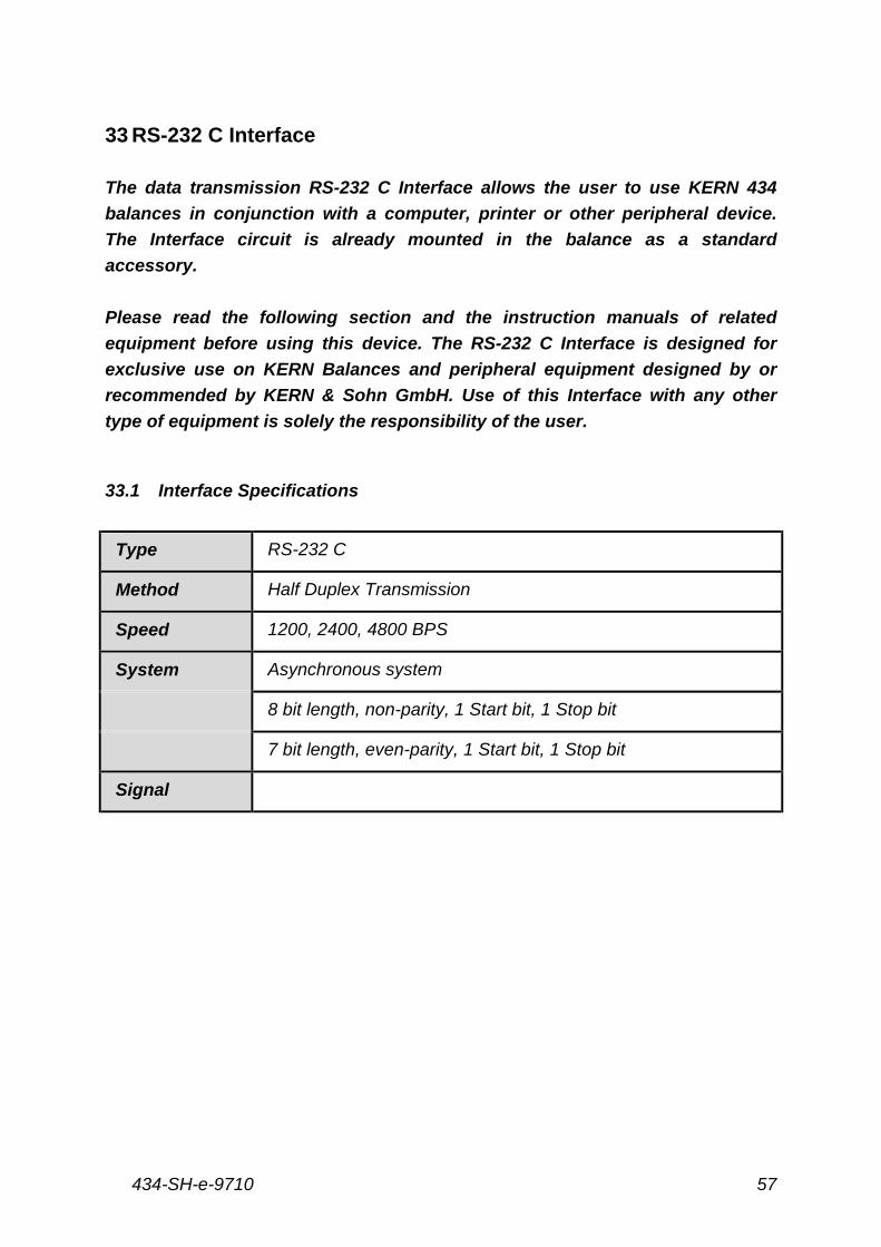
33 RS-232 C Interface
The data transmission RS-232 C Interface allows the user to use KERN 434
balances in conjunction with a computer, printer or other peripheral device.
The Interface circuit is already mounted in the balance as a standard
accessory.
Please read the following section and the instruction manuals of related
equipment before using this device. The RS-232 C Interface is designed for
exclusive use on KERN Balances and peripheral equipment designed by or
recommended by KERN & Sohn GmbH. Use of this Interface with any other
type of equipment is solely the responsibility of the user.
33.1 Interface Specifications
Type RS-232 C
Method Half Duplex Transmission
Speed 1200, 2400, 4800 BPS
System Asynchronous system
8 bit length, non-parity, 1 Start bit, 1 Stop bit
7 bit length, even-parity, 1 Start bit, 1 Stop bit
Signal
434-SH-e-971058
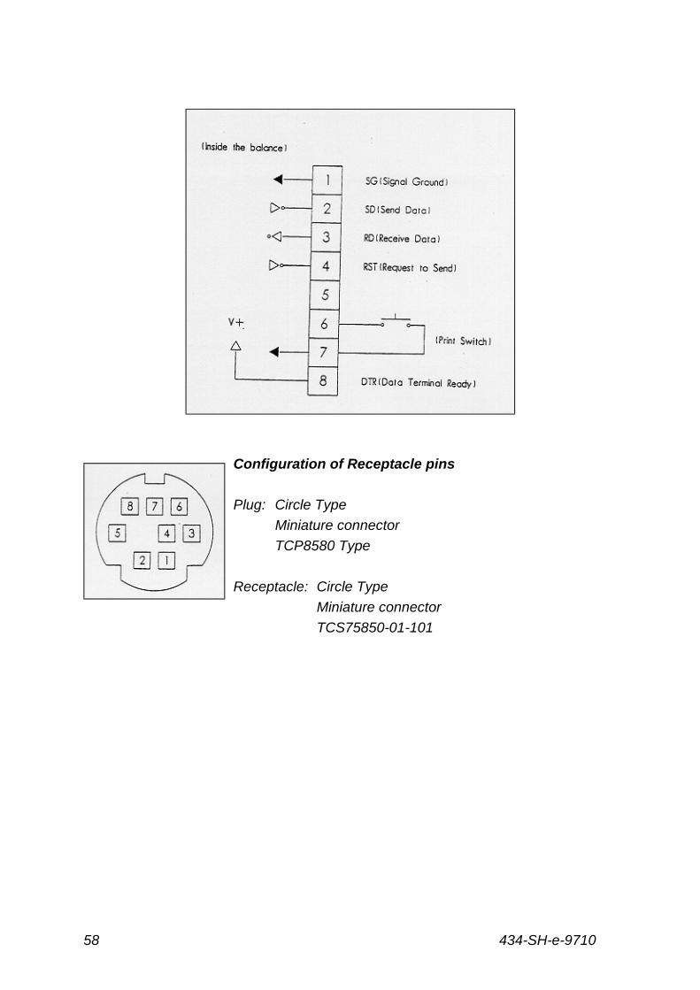
Configuration of Receptacle pins
Plug: Circle Type
Miniature connector
TCP8580 Type
Receptacle: Circle Type
Miniature connector
TCS75850-01-101
434-SH-e-9710 59
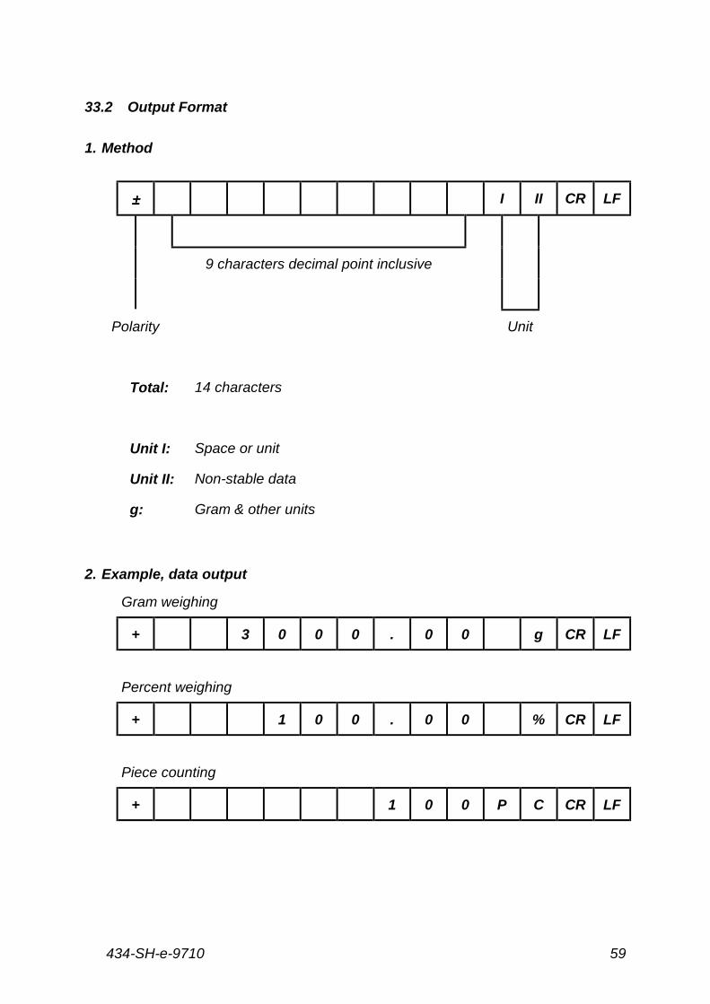
33.2 Output Format
1. Method
±±±± I II CR LF
9 characters decimal point inclusive
Polarity Unit
Total: 14 characters
Unit I: Space or unit
Unit II: Non-stable data
g: Gram & other units
2. Example, data output
Gram weighing
+ 3 0 0 0 . 0 0 g CR LF
Percent weighing
+ 1 0 0 . 0 0 % CR LF
Piece counting
+ 1 0 0 P C CR LF
434-SH-e-971060
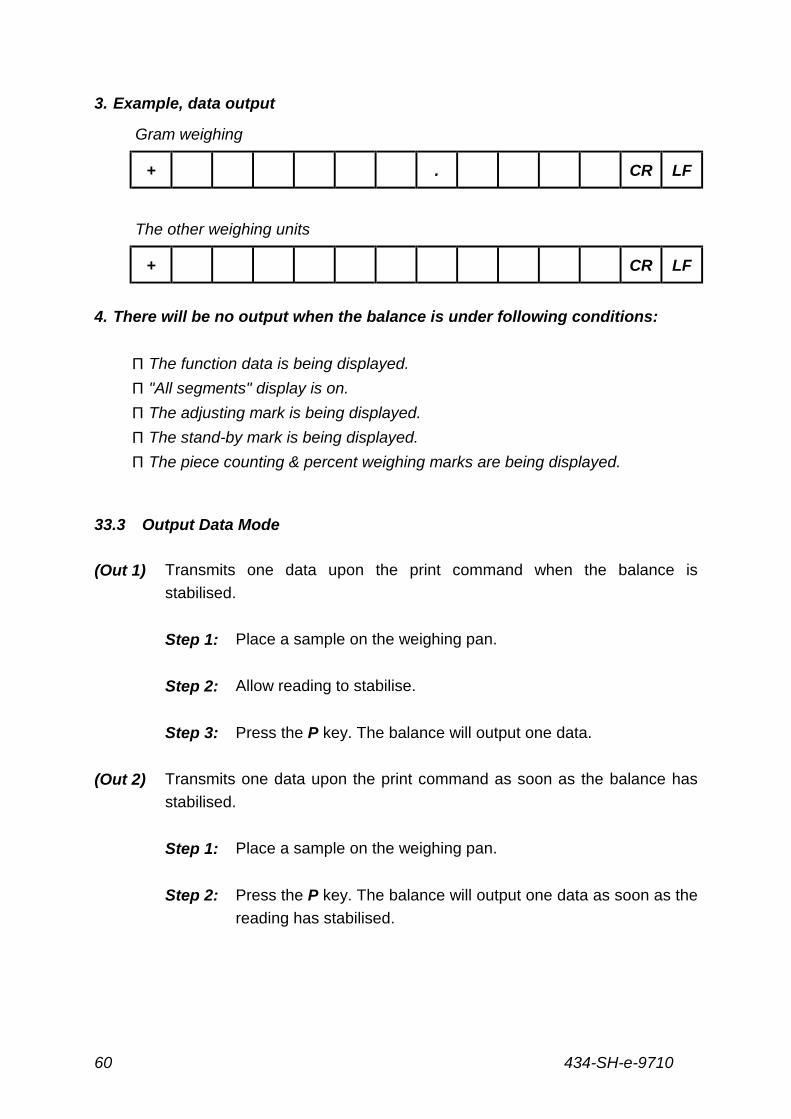
3. Example, data output
Gram weighing
+ . CR LF
The other weighing units
+ CR LF
4. There will be no output when the balance is under following conditions:
Π The function data is being displayed.
Π "All segments" display is on.
Π The adjusting mark is being displayed.
Π The stand-by mark is being displayed.
Π The piece counting & percent weighing marks are being displayed.
33.3 Output Data Mode
(Out 1) Transmits one data upon the print command when the balance is
stabilised.
Step 1: Place a sample on the weighing pan.
Step 2: Allow reading to stabilise.
Step 3: Press the P key. The balance will output one data.
(Out 2) Transmits one data upon the print command as soon as the balance has
stabilised.
Step 1: Place a sample on the weighing pan.
Step 2: Press the P key. The balance will output one data as soon as the
reading has stabilised.
434-SH-e-9710 61
(Out 3) Transmits one data upon the print command even if the balance has not
stabilised.
Step 1: Place a sample on the weighing pan.
Step 2: Press the P key. The balance will output one data even if the
reading has not stabilised.
(Out 4) Automatically transmits one data when the balance has stabilised.
Step 1: Place a sample on the weighing pan.
Step 2: When the reading stabilises the balance will automatically output
one data without pressing the P key.
Step 3: Remove the sample and place another sample on the pan.
Step 4: The balance will automatically output another data after the
reading has stabilised.
(Out 5) Automatically transmits all data regardless of whether the balance has
stabilised or not.
Step 1: Place a sample on the weighing pan. The balance will
automatically output all data.
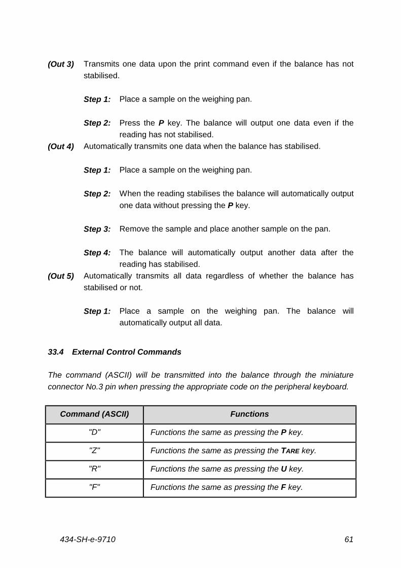
33.4 External Control Commands
The command (ASCII) will be transmitted into the balance through the miniature
connector No.3 pin when pressing the appropriate code on the peripheral keyboard.
Command (ASCII) Functions
"D" Functions the same as pressing the P key.
"Z" Functions the same as pressing the TARE key.
"R" Functions the same as pressing the U key.
"F" Functions the same as pressing the F key.
434-SH-e-971062
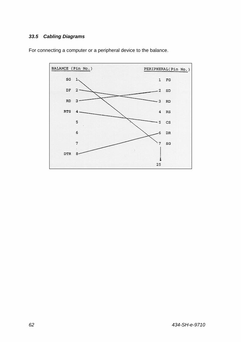
33.5 Cabling Diagrams
For connecting a computer or a peripheral device to the balance.
434-SH-e-9710 63
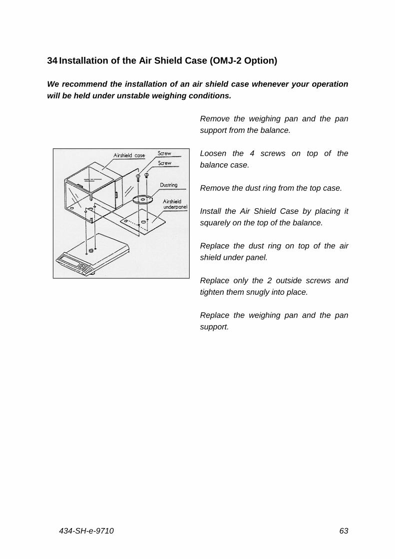
34 Installation of the Air Shield Case (OMJ-2 Option)
We recommend the installation of an air shield case whenever your operation
will be held under unstable weighing conditions.
Remove the weighing pan and the pan
support from the balance.
Loosen the 4 screws on top of the
balance case.
Remove the dust ring from the top case.
Install the Air Shield Case by placing it
squarely on the top of the balance.
Replace the dust ring on top of the air
shield under panel.
Replace only the 2 outside screws and
tighten them snugly into place.
Replace the weighing pan and the pan
support.
434-SH-e-971064
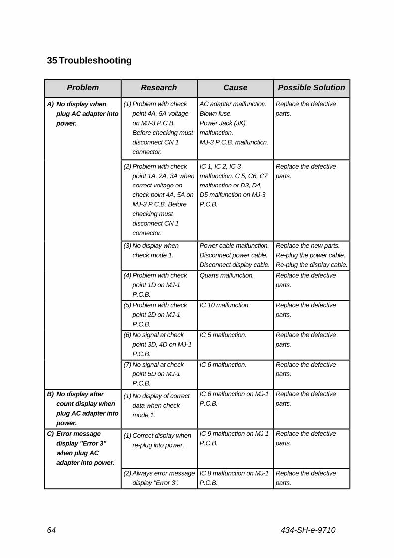
35 Troubleshooting
Problem Research Cause Possible Solution
A) No display when
plug AC adapter into
power.
(1) Problem with check
point 4A, 5A voltage
on MJ-3 P.C.B.
Before checking must
disconnect CN 1
connector.
AC adapter malfunction.
Blown fuse.
Power Jack (JK)
malfunction.
MJ-3 P.C.B. malfunction.
Replace the defective
parts.
(2) Problem with check
point 1A, 2A, 3A when
correct voltage on
check point 4A, 5A on
MJ-3 P.C.B. Before
checking must
disconnect CN 1
connector.
IC 1, IC 2, IC 3
malfunction. C 5, C6, C7
malfunction or D3, D4,
D5 malfunction on MJ-3
P.C.B.
Replace the defective
parts.
(3) No display when
check mode 1.
Power cable malfunction.
Disconnect power cable.
Disconnect display cable.
Replace the new parts.
Re-plug the power cable.
Re-plug the display cable.
(4) Problem with check
point 1D on MJ-1
P.C.B.
Quarts malfunction. Replace the defective
parts.
(5) Problem with check
point 2D on MJ-1
P.C.B.
IC 10 malfunction. Replace the defective
parts.
(6) No signal at check
point 3D, 4D on MJ-1
P.C.B.
IC 5 malfunction. Replace the defective
parts.
(7) No signal at check
point 5D on MJ-1
P.C.B.
IC 6 malfunction. Replace the defective
parts.
B) No display after
count display when
plug AC adapter into
power.
(1) No display of correct
data when check
mode 1.
IC 6 malfunction on MJ-1
P.C.B.
Replace the defective
parts.
C) Error message
display "Error 3"
when plug AC
adapter into power.
(1) Correct display when
re-plug into power.
IC 9 malfunction on MJ-1
P.C.B.
Replace the defective
parts.
(2) Always error message
display "Error 3".
IC 8 malfunction on MJ-1
P.C.B.
Replace the defective
parts.
434-SH-e-9710 65
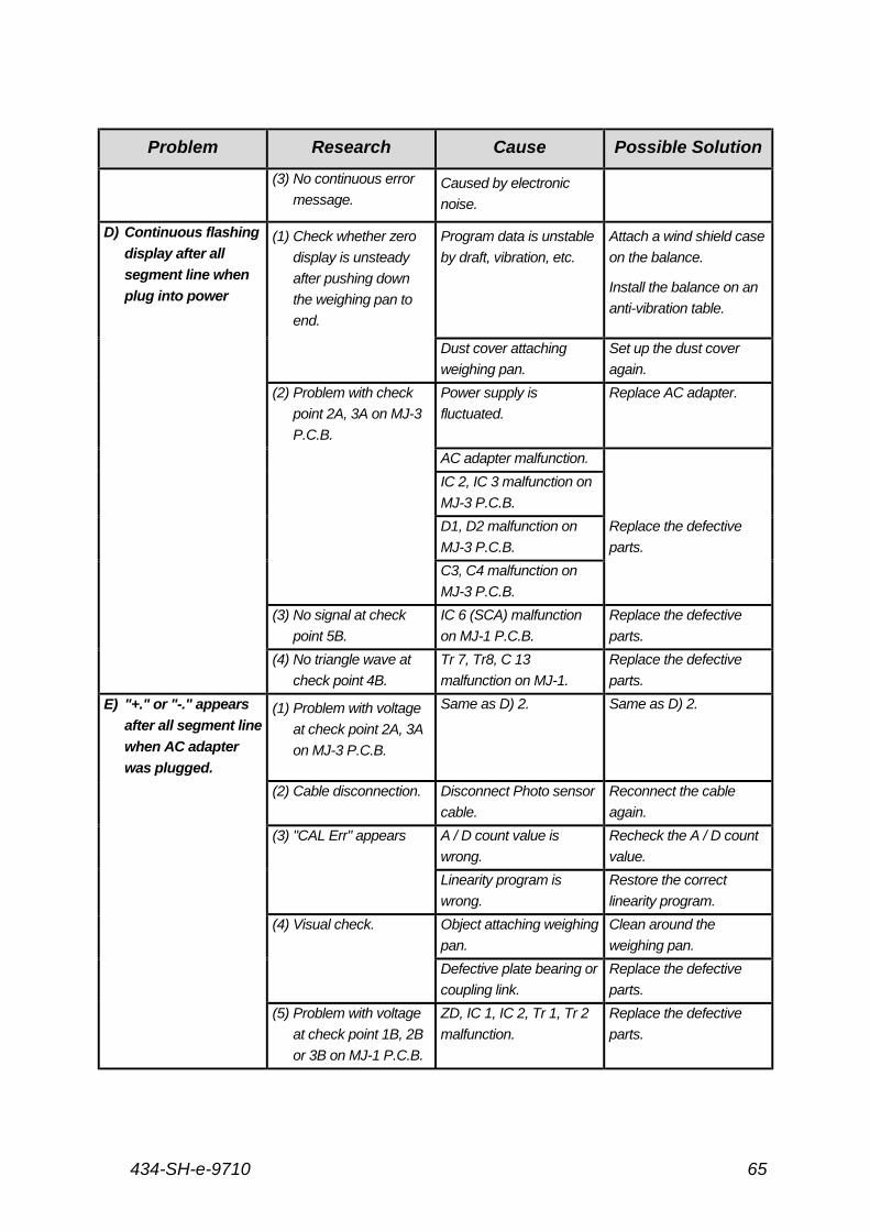
Problem Research Cause Possible Solution
(3) No continuous error
message.Caused by electronic
noise.
D) Continuous flashing
display after all
segment line when
plug into power
(1) Check whether zero
display is unsteady
after pushing down
the weighing pan to
end.
Program data is unstable
by draft, vibration, etc.
Attach a wind shield case
on the balance.
Install the balance on an
anti-vibration table.
Dust cover attaching
weighing pan.
Set up the dust cover
again.
(2) Problem with check
point 2A, 3A on MJ-3
P.C.B.
Power supply is
fluctuated.
Replace AC adapter.
AC adapter malfunction.
IC 2, IC 3 malfunction on
MJ-3 P.C.B.
D1, D2 malfunction on
MJ-3 P.C.B.
Replace the defective
parts.
C3, C4 malfunction on
MJ-3 P.C.B.
(3) No signal at check
point 5B.
IC 6 (SCA) malfunction
on MJ-1 P.C.B.
Replace the defective
parts.
(4) No triangle wave at
check point 4B.
Tr 7, Tr8, C 13
malfunction on MJ-1.
Replace the defective
parts.
E) "+." or "-." appears
after all segment line
when AC adapter
was plugged.
(1) Problem with voltage
at check point 2A, 3A
on MJ-3 P.C.B.
Same as D) 2. Same as D) 2.
(2) Cable disconnection. Disconnect Photo sensor
cable.
Reconnect the cable
again.
(3) "CAL Err" appears A / D count value is
wrong.
Recheck the A / D count
value.
Linearity program is
wrong.
Restore the correct
linearity program.
(4) Visual check. Object attaching weighing
pan.
Clean around the
weighing pan.
Defective plate bearing or
coupling link.
Replace the defective
parts.
(5) Problem with voltage
at check point 1B, 2B
or 3B on MJ-1 P.C.B.
ZD, IC 1, IC 2, Tr 1, Tr 2
malfunction.
Replace the defective
parts.
434-SH-e-971066
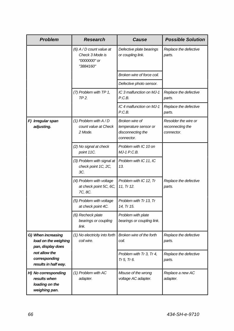
Problem Research Cause Possible Solution
(6) A / D count value at
Check 3 Mode is
"0000000" or
"3884160"
Defective plate bearings
or coupling link.
Replace the defective
parts.
Broken wire of force coil.
Defective photo sensor.
(7) Problem with TP 1,
TP 2.
IC 3 malfunction on MJ-1
P.C.B.
Replace the defective
parts.
IC 4 malfunction on MJ-1
P.C.B.
Replace the defective
parts.
F) Irregular span
adjusting.
(1) Problem with A / D
count value at Check
2 Mode.
Broken wire of
temperature sensor or
disconnecting the
connector.
Resolder the wire or
reconnecting the
connector.
(2) No signal at check
point 11C.
Problem with IC 10 on
MJ-1 P.C.B.
(3) Problem with signal at
check point 1C, 2C,
3C.
Problem with IC 11, IC
13.
(4) Problem with voltage
at check point 5C, 6C,
7C, 8C.
Problem with IC 12, Tr
11, Tr 12.
Replace the defective
parts.
(5) Problem with voltage
at check point 4C.
Problem with Tr 13, Tr
14, Tr 15.
(6) Recheck plate
bearings or coupling
link.
Problem with plate
bearings or coupling link.
G) When increasing
load on the weighing
pan, display does
(1) No electricity into forth
coil wire.
Broken wire of the forth
coil.
Replace the defective
parts.
not allow the
corresponding
results in half way.
Problem with Tr 3, Tr 4,
Tr 5, Tr 6.
Replace the defective
parts.
H) No corresponding
results when
loading on the
weighing pan.
(1) Problem with AC
adapter.
Misuse of the wrong
voltage AC adapter.
Replace a new AC
adapter.
434-SH-e-9710 67
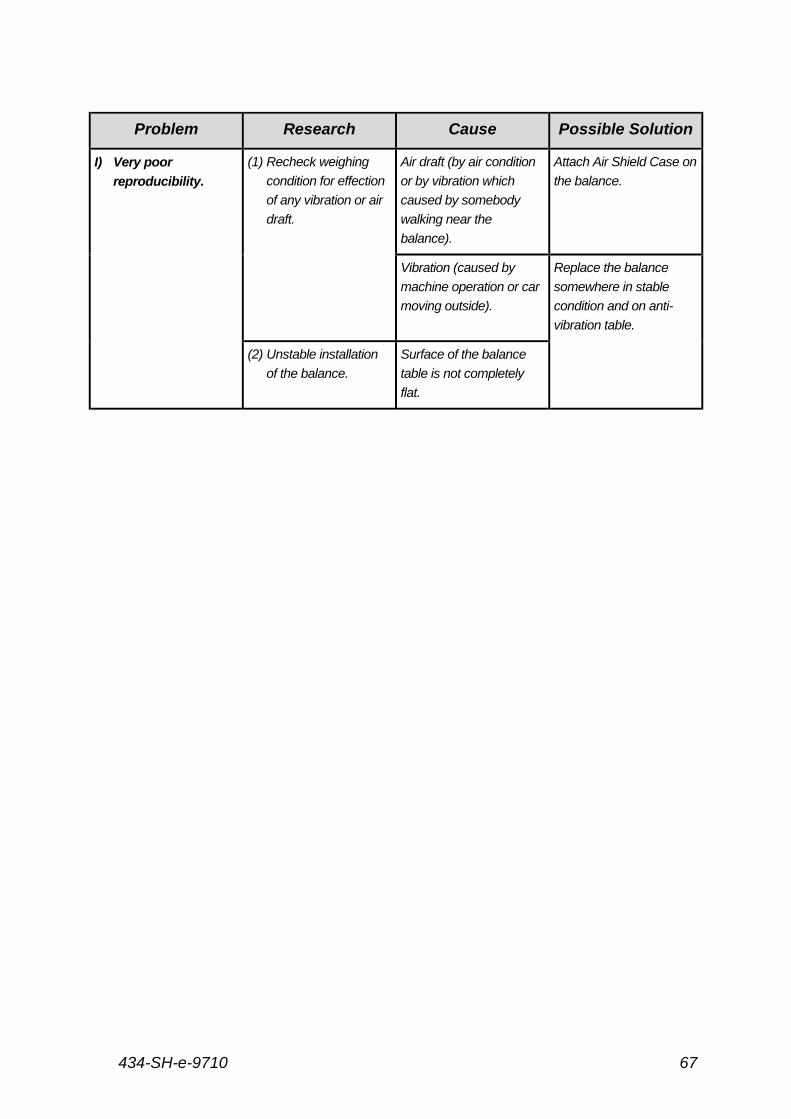
Problem Research Cause Possible Solution
I) Very poor
reproducibility.
(1) Recheck weighing
condition for effection
of any vibration or air
draft.
Air draft (by air condition
or by vibration which
caused by somebody
walking near the
balance).
Attach Air Shield Case on
the balance.
Vibration (caused by
machine operation or car
moving outside).
Replace the balance
somewhere in stable
condition and on anti-
vibration table.
(2) Unstable installation
of the balance.
Surface of the balance
table is not completely
flat.
434-SH-e-971068
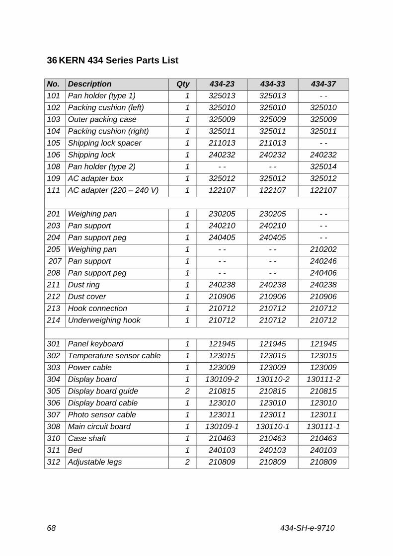
36 KERN 434 Series Parts List
No. Description Qty 434-23 434-33 434-37
101 Pan holder (type 1) 1 325013 325013 - -
102 Packing cushion (left) 1 325010 325010 325010
103 Outer packing case 1 325009 325009 325009
104 Packing cushion (right) 1 325011 325011 325011
105 Shipping lock spacer 1 211013 211013 - -
106 Shipping lock 1 240232 240232 240232
108 Pan holder (type 2) 1 - - - - 325014
109 AC adapter box 1 325012 325012 325012
111 AC adapter (220 – 240 V) 1 122107 122107 122107
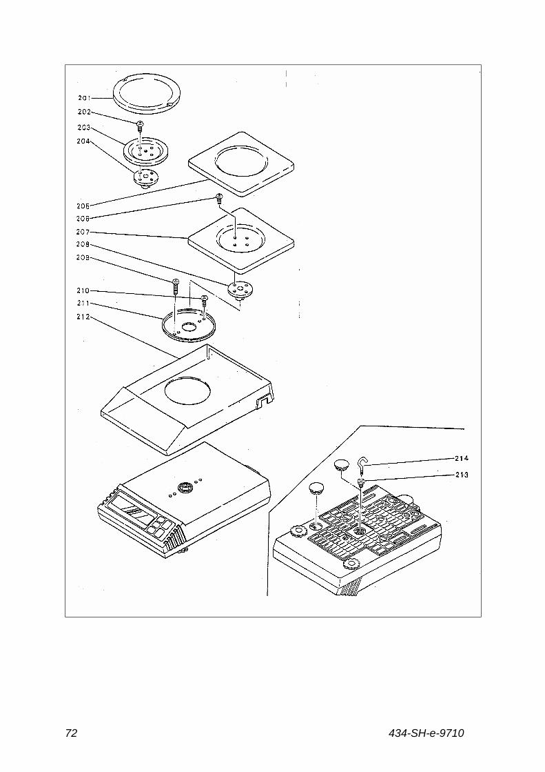
201 Weighing pan 1 230205 230205 - -
203 Pan support 1 240210 240210 - -
204 Pan support peg 1 240405 240405 - -
205 Weighing pan 1 - - - - 210202
207 Pan support 1 - - - - 240246
208 Pan support peg 1 - - - - 240406
211 Dust ring 1 240238 240238 240238
212 Dust cover 1 210906 210906 210906
213 Hook connection 1 210712 210712 210712
214 Underweighing hook 1 210712 210712 210712
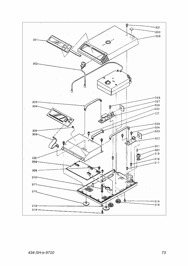
301 Panel keyboard 1 121945 121945 121945
302 Temperature sensor cable 1 123015 123015 123015
303 Power cable 1 123009 123009 123009
304 Display board 1 130109-2 130110-2 130111-2
305 Display board guide 2 210815 210815 210815
306 Display board cable 1 123010 123010 123010
307 Photo sensor cable 1 123011 123011 123011
308 Main circuit board 1 130109-1 130110-1 130111-1
310 Case shaft 1 210463 210463 210463
311 Bed 1 240103 240103 240103
312 Adjustable legs 2 210809 210809 210809
434-SH-e-9710 69
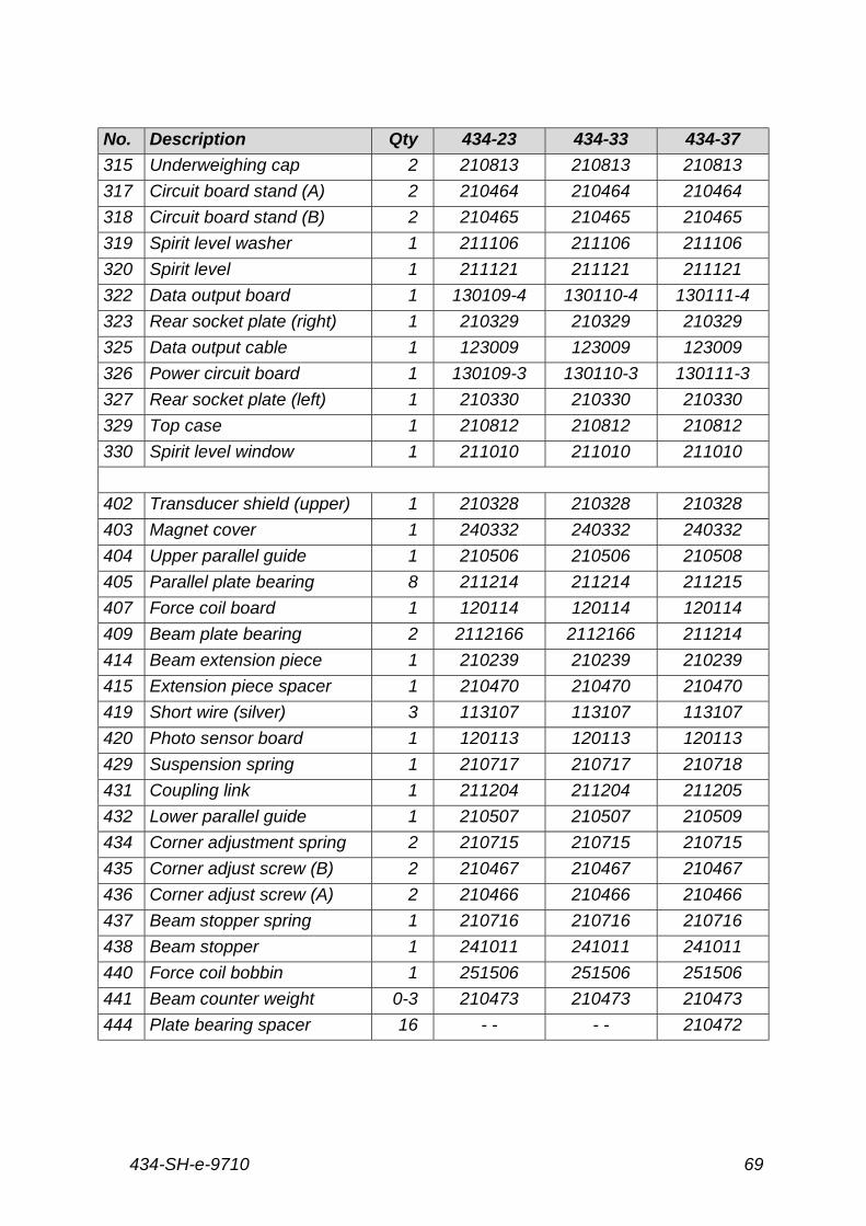
No. Description Qty 434-23 434-33 434-37
315 Underweighing cap 2 210813 210813 210813
317 Circuit board stand (A) 2 210464 210464 210464
318 Circuit board stand (B) 2 210465 210465 210465
319 Spirit level washer 1 211106 211106 211106
320 Spirit level 1 211121 211121 211121
322 Data output board 1 130109-4 130110-4 130111-4
323 Rear socket plate (right) 1 210329 210329 210329
325 Data output cable 1 123009 123009 123009
326 Power circuit board 1 130109-3 130110-3 130111-3
327 Rear socket plate (left) 1 210330 210330 210330
329 Top case 1 210812 210812 210812
330 Spirit level window 1 211010 211010 211010
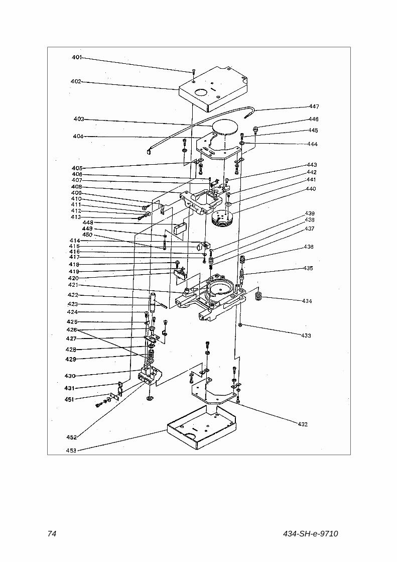
402 Transducer shield (upper) 1 210328 210328 210328
403 Magnet cover 1 240332 240332 240332
404 Upper parallel guide 1 210506 210506 210508
405 Parallel plate bearing 8 211214 211214 211215
407 Force coil board 1 120114 120114 120114
409 Beam plate bearing 2 2112166 2112166 211214
414 Beam extension piece 1 210239 210239 210239
415 Extension piece spacer 1 210470 210470 210470
419 Short wire (silver) 3 113107 113107 113107
420 Photo sensor board 1 120113 120113 120113
429 Suspension spring 1 210717 210717 210718
431 Coupling link 1 211204 211204 211205
432 Lower parallel guide 1 210507 210507 210509
434 Corner adjustment spring 2 210715 210715 210715
435 Corner adjust screw (B) 2 210467 210467 210467
436 Corner adjust screw (A) 2 210466 210466 210466
437 Beam stopper spring 1 210716 210716 210716
438 Beam stopper 1 241011 241011 241011
440 Force coil bobbin 1 251506 251506 251506
441 Beam counter weight 0-3 210473 210473 210473
444 Plate bearing spacer 16 - - - - 210472
434-SH-e-971070
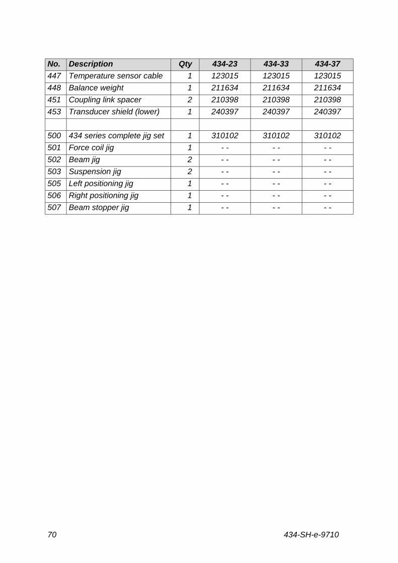
No. Description Qty 434-23 434-33 434-37
447 Temperature sensor cable 1 123015 123015 123015
448 Balance weight 1 211634 211634 211634
451 Coupling link spacer 2 210398 210398 210398
453 Transducer shield (lower) 1 240397 240397 240397
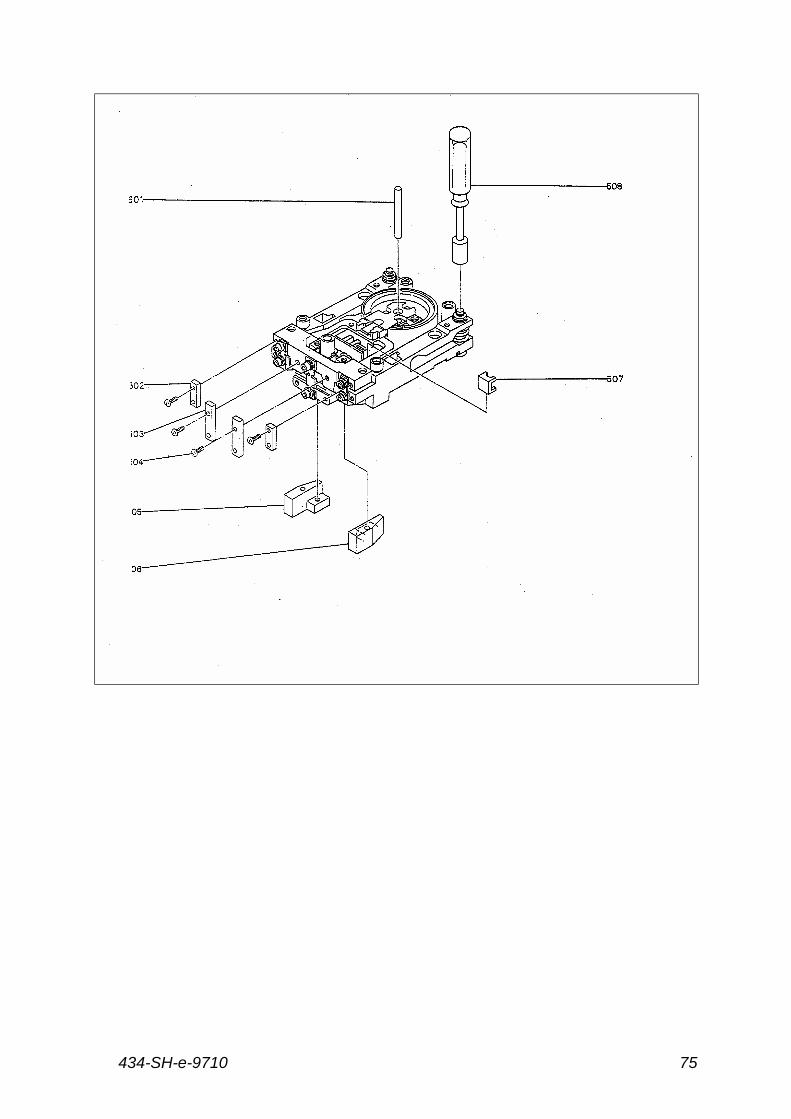
500 434 series complete jig set 1 310102 310102 310102
501 Force coil jig 1 - - - - - -
502 Beam jig 2 - - - - - -
503 Suspension jig 2 - - - - - -
505 Left positioning jig 1 - - - - - -
506 Right positioning jig 1 - - - - - -
507 Beam stopper jig 1 - - - - - -
434-SH-e-9710 71
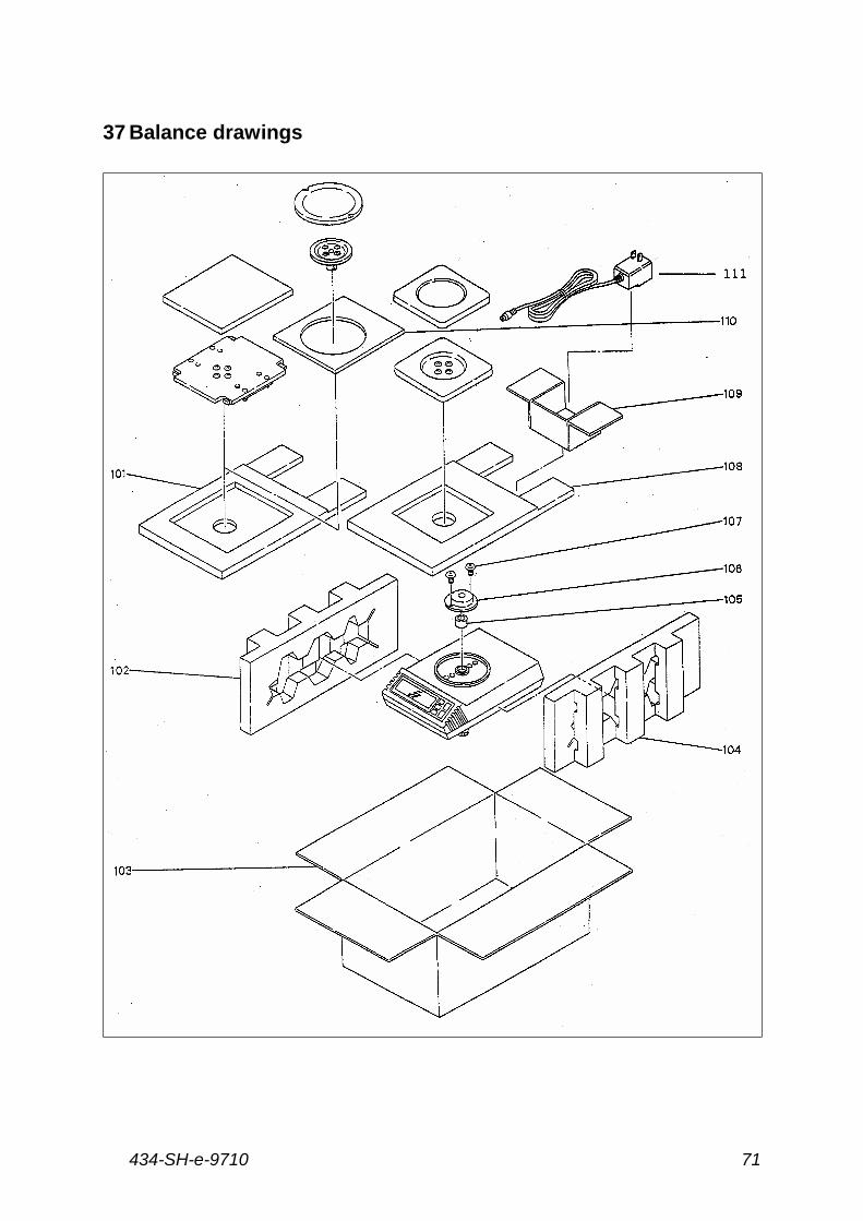
37 Balance drawings
434-SH-e-971072
434-SH-e-9710 73
434-SH-e-971074
434-SH-e-9710 75