Embed Size (px)
Citation preview

KERN & Sohn GmbH Ziegelei 1 D-72336 Balingen E-Mail: [email protected]
Tel: +49-[0]7433- 9933-0 Fax: +49-[0]7433-9933-149 Internet: www.kern-sohn.com
Operating instruction Analytical and precision balances
KERN 770/GS/GJ Version 2.3 04/2000 GB
770/GS/GJ-BA-e-0023
2 770/GS/GJ-BA-e-0023
GB
KERN 770/GS/GJ Version 2.3 04/2000 Operating instruction Analytical and precision balances
Contents
1 OPERATING ELEMENTS..................................................................................................... 4
1.1 IMPORTANT INSTRUCTIONS .............................................................................................. 9 1.2 GETTING STARTED ........................................................................................................ 10
1.2.1 Installation of the weighing chamber ....................................................................... 10 1.2.2 Connecting the Balance to AC Power ..................................................................... 12 1.2.3 Safety Precautions................................................................................................... 13 1.2.4 Connecting Electronic Peripheral Devices............................................................... 13 1.2.5 Levelling the Balance Using the Level Indicator ...................................................... 13
1.3 OPERATING THE BALANCE ............................................................................................. 14 1.3.1 Warm-up Time ......................................................................................................... 14 1.3.2 Turning the Balance On and Off (Standby Mode) ................................................... 14 1.3.3 Self-Test .................................................................................................................. 14 1.3.4 Taring....................................................................................................................... 15 1.3.5 Simple Weighing (Weight Determination)................................................................ 15
1.4 ADJUSTING (FORMERLY CALIBRATION) ........................................................................... 16 1.4.1 Internal Adjusting for Balances with a Built-in Adjusting Weight............................. 16 1.4.2 External Adjusting.................................................................................................... 17 1.4.3 Blocking the Adjusting Functions............................................................................. 17
1.5 DATA INTERFACE........................................................................................................... 18 1.6 BELOW BALANCE WEIGHING .......................................................................................... 19 1.7 ANTI-THEFT LOCKING DEVICE ........................................................................................ 19 1.8 TROUBLESHOOTING GUIDE ............................................................................................ 20 1.9 CARE AND MAINTENANCE .............................................................................................. 21
1.9.1 Cleaning................................................................................................................... 21 1.9.2 Safety Inspection ..................................................................................................... 21
2 DECLARATIONS OF CONFORMITY................................................................................. 22
3 BALANCE OPERATING MENU ......................................................................................... 24
3.1 CHANGING MENU CODE SETTINGS................................................................................. 24 3.1.1 Accessing the Menu ................................................................................................ 25 3.1.2 Reset Function - Undoing All Menu Code Changes ................................................ 26
3.2 BALANCE OPERATING PARAMETERS .............................................................................. 27 3.2.1 Adapting the Balance to Ambient Conditions .......................................................... 27 3.2.2 Standard Weighing Mode - Manual Filling Mode..................................................... 27 3.2.3 Stability Range......................................................................................................... 27 3.2.4 Tare Parameter........................................................................................................ 28 3.2.5 Auto Zero Function .................................................................................................. 28 3.2.6 Adjusting and Linearisation Functions Using CAL................................................... 28
3.3 UNIT CONVERSION ........................................................................................................ 29 3.3.1 Weight Units ............................................................................................................ 29
3.4 INTERFACE PARAMETER SETTINGS ................................................................................ 30 3.4.1 Baud Rate................................................................................................................ 30
770/GS/GJ-BA-e-0023 3
3.4.2 Parity........................................................................................................................ 30 3.4.3 Number of Stop Bits................................................................................................. 30 3.4.4 Handshake Mode..................................................................................................... 30
3.5 DATA INTERFACE........................................................................................................... 31 3.5.1 Data Output Parameter............................................................................................ 31 3.5.2 Auto Print ................................................................................................................. 31 3.5.3 Data Output at Defined Intervals ............................................................................. 32 3.5.4 Automatic Taring after Data Output ......................................................................... 32 3.5.5 Data ID Codes ......................................................................................................... 33 3.5.6 Automatic Output of the Tare Memory Data ............................................................ 33
3.6 ADDITIONAL FUNCTIONS ................................................................................................ 33
4 APPLICATION PROGRAMS .............................................................................................. 34
4.1 TARE MEMORY.............................................................................................................. 34 4.2 PRACTICAL EXAMPLE “NET TOTAL“ ................................................................................ 35 4.3 WEIGHING IN PERCENT.................................................................................................. 36 4.4 PRACTICAL EXAMPLE “DETERMINATION OF THE RESIDUAL WEIGHT IN PERCENT“............ 37 4.5 COUNTING .................................................................................................................... 38 4.6 PRACTICAL EXAMPLE “COUNTING SMALL PARTS“ ........................................................... 39 4.7 ANIMAL WEIGHING/AVERAGING...................................................................................... 40 4.8 PRACTICAL EXAMPLE “ANIMAL WEIGHING IN THE AUTOMATIC START MODE“ .................. 42 4.9 PRACTICAL EXAMPLE “ANIMAL WEIGHING IN THE MANUAL START MODE“ ........................ 43
5 ISO/GLP-COMPLIANT PRINTOUT OR RECORD ............................................................. 44
5.1 DATA PRINTOUT/RECORD (ISO/GLP-COMPLIANT).......................................................... 46 5.2 DATA PRINTOUT/RECORD FOR APPLICATION PROGRAMS (E.G. COUNTING) ..................... 47
6 INTERFACE DESCRIPTION .............................................................................................. 48
6.1 GENERAL INFORMATION ................................................................................................ 48 6.2 INTERFACING DEVICES WITH THE BALANCE .................................................................... 48 6.3 GENERAL SPECIFICATIONS ............................................................................................ 49 6.4 DATA OUTPUT FORMATS ............................................................................................... 50 6.5 DATA INPUT FORMATS................................................................................................... 54 6.6 SYNCHRONISATION AND DATA OUTPUT PARAMETERS .................................................... 57 6.7 INTERFACE PARAMETER SETTINGS ................................................................................ 60 6.8 PIN ASSIGNMENT CHART ............................................................................................... 61
7 SPECIFICATIONS .............................................................................................................. 63
8 SUPPLEMENT - OVERVIEW OF ALL MENU SETTINGS................................................. 66 Please read through these installation and operating instructions carefully before operating your new balance. After unpacking the balance, please check it immediately for any visible damage as a result of rough handling during shipment. If this is the case, proceed as directed in the section entitled "Safety Inspection." Save the box and all parts of the packaging for any future shipment of your balance. Before packing your balance, unplug all connected cables to prevent damage.

4 770/GS/GJ-BA-e-0023
1 Operating Elements
KERN 770-12, KERN 770-13, KERN 770-14, KERN 770-15
No. Designation No. Designation
1 Weighing pan 13 Verification ID label with metrological data 2 Shield ring for verified balances approved for use as 3 Metrological ID label for verified balances legal measuring instruments approved for use as legal measuring 14 AC jack instruments 15 Manufacturer’s label with the CE mark of 4 Menu access switch conformity 5 Levelling foot 16 Data interface port 6 TARE key 17 Level indicator 7 PRINT key (data output) 8 Function key F 9 CAL key
10 CF key (clear function) Not shown: 11 ON/OFF key Dust cover 12 Weight display Caps and plugs (set)
770/GS/GJ-BA-e-0023 5
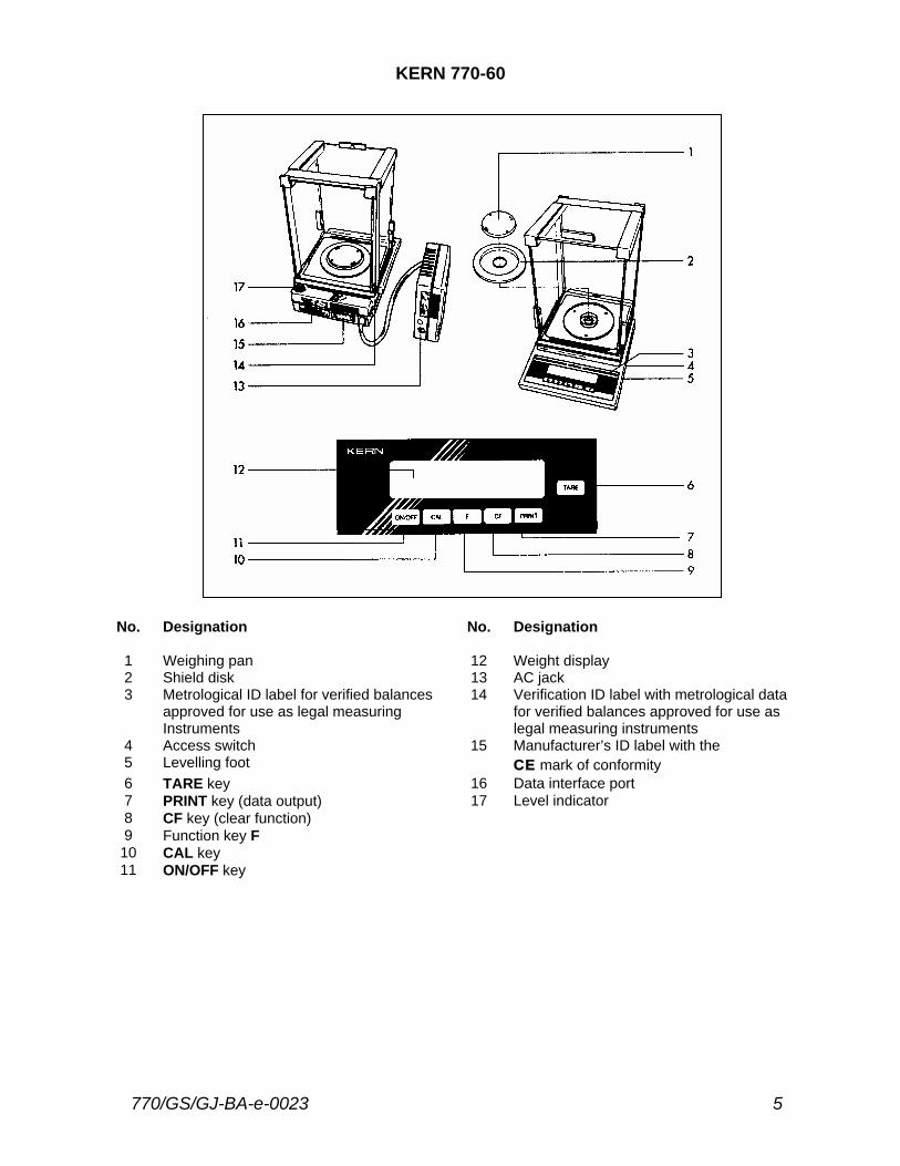
KERN 770-60
No. Designation No. Designation
1 Weighing pan 12 Weight display 2 Shield disk 13 AC jack 3 Metrological ID label for verified balances 14 Verification ID label with metrological data approved for use as legal measuring for verified balances approved for use as Instruments legal measuring instruments 4 Access switch 15 Manufacturer’s ID label with the 5 Levelling foot CE mark of conformity 6 TARE key 16 Data interface port 7 PRINT key (data output) 17 Level indicator 8 CF key (clear function) 9 Function key F
10 CAL key 11 ON/OFF key
6 770/GS/GJ-BA-e-0023
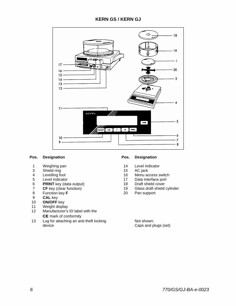
KERN GS / KERN GJ
Pos. Designation Pos. Designation
1 Weighing pan 14 Level indicator 3 Shield ring 15 AC jack 4 Levelling foot 16 Menu access switch 5 Level indicator 17 Data interface port 6 PRINT key (data output) 18 Draft shield cover 7 CF key (clear function) 19 Glass draft shield cylinder 8 Function key F 20 Pan support 9 CAL key
10 ON/OFF key 11 Weight display 12 Manufacturer’s ID label with the
CE mark of conformity 13 Lug for attaching an anti-theft locking Not shown:
device Caps and plugs (set)
770/GS/GJ-BA-e-0023 7
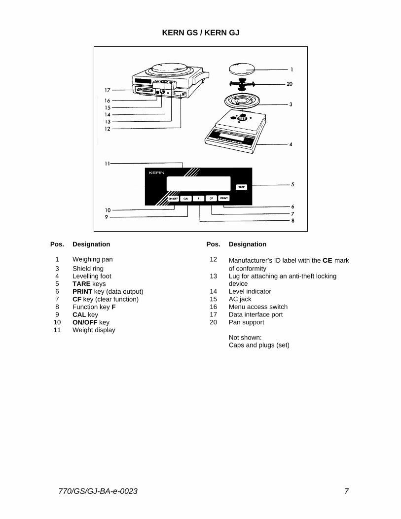
KERN GS / KERN GJ
Pos. Designation Pos. Designation
1 Weighing pan 12 Manufacturer’s ID label with the CE mark 3 Shield ring of conformity 4 Levelling foot 13 Lug for attaching an anti-theft locking 5 TARE keys device 6 PRINT key (data output) 14 Level indicator 7 CF key (clear function) 15 AC jack 8 Function key F 16 Menu access switch 9 CAL key 17 Data interface port
10 ON/OFF key 20 Pan support 11 Weight display
Not shown: Caps and plugs (set)
8 770/GS/GJ-BA-e-0023
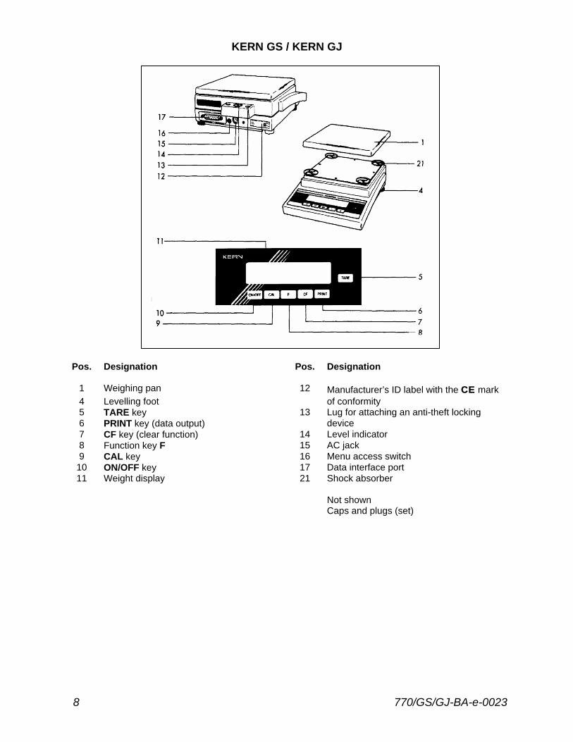
KERN GS / KERN GJ
Pos. Designation Pos. Designation
1 Weighing pan 12 Manufacturer’s ID label with the CE mark 4 Levelling foot of conformity 5 TARE key 13 Lug for attaching an anti-theft locking 6 PRINT key (data output) device 7 CF key (clear function) 14 Level indicator 8 Function key F 15 AC jack 9 CAL key 16 Menu access switch
10 ON/OFF key 17 Data interface port 11 Weight display 21 Shock absorber
Not shown Caps and plugs (set)
770/GS/GJ-BA-e-0023 9
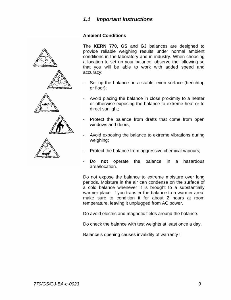
1.1 Important Instructions Ambient Conditions The KERN 770, GS and GJ balances are designed to provide reliable weighing results under normal ambient conditions in the laboratory and in industry. When choosing a location to set up your balance, observe the following so that you will be able to work with added speed and accuracy: - Set up the balance on a stable, even surface (benchtop
or floor); - Avoid placing the balance in close proximity to a heater
or otherwise exposing the balance to extreme heat or to direct sunlight;
- Protect the balance from drafts that come from open
windows and doors; - Avoid exposing the balance to extreme vibrations during
weighing; - Protect the balance from aggressive chemical vapours; - Do not operate the balance in a hazardous
area/location. Do not expose the balance to extreme moisture over long periods. Moisture in the air can condense on the surface of a cold balance whenever it is brought to a substantially warmer place. If you transfer the balance to a warmer area, make sure to condition it for about 2 hours at room temperature, leaving it unplugged from AC power. Do avoid electric and magnetic fields around the balance. Do check the balance with test weights at least once a day. Balance’s opening causes invalidity of warranty !
10 770/GS/GJ-BA-e-0023
1.2 Getting started Remove the plastic sheeting, adhesive tapes and foam material from the balance. Important information:
Control Seals on Verified Balances Approved for Use as Legal Measuring Instruments in the EU*: Legal regulations require the verified balance to be sealed. This control seal consists of an adhesive label with the name „KERN“ on it. This seal will be irreparably damaged if you attempt to remove it. In this case, the validity of the seal becomes void and you must have your balance re-verified.
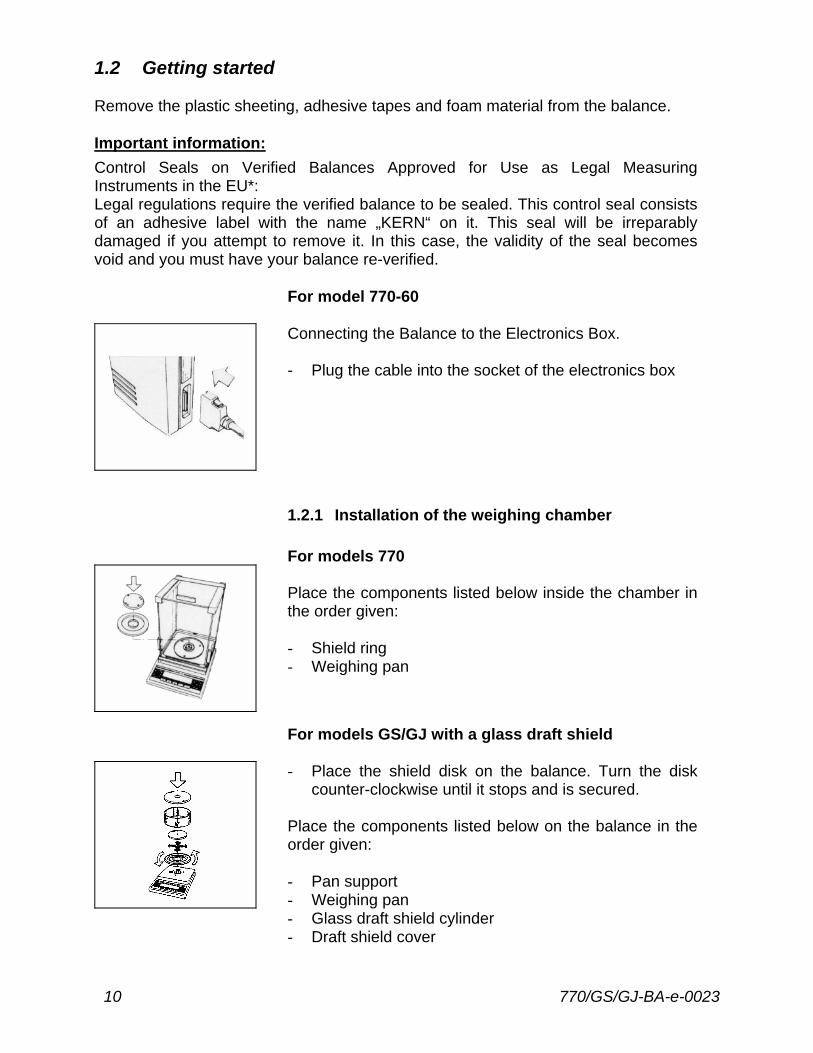
For model 770-60 Connecting the Balance to the Electronics Box. - Plug the cable into the socket of the electronics box
1.2.1 Installation of the weighing chamber
For models 770 Place the components listed below inside the chamber in the order given: - Shield ring - Weighing pan
For models GS/GJ with a glass draft shield - Place the shield disk on the balance. Turn the disk
counter-clockwise until it stops and is secured. Place the components listed below on the balance in the order given: - Pan support - Weighing pan - Glass draft shield cylinder - Draft shield cover
770/GS/GJ-BA-e-0023 11
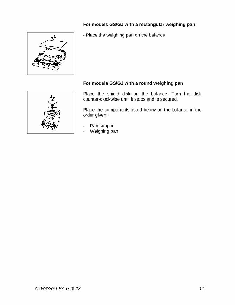
For models GS/GJ with a rectangular weighing pan - Place the weighing pan on the balance
For models GS/GJ with a round weighing pan Place the shield disk on the balance. Turn the disk counter-clockwise until it stops and is secured. Place the components listed below on the balance in the order given: - Pan support - Weighing pan
12 770/GS/GJ-BA-e-0023
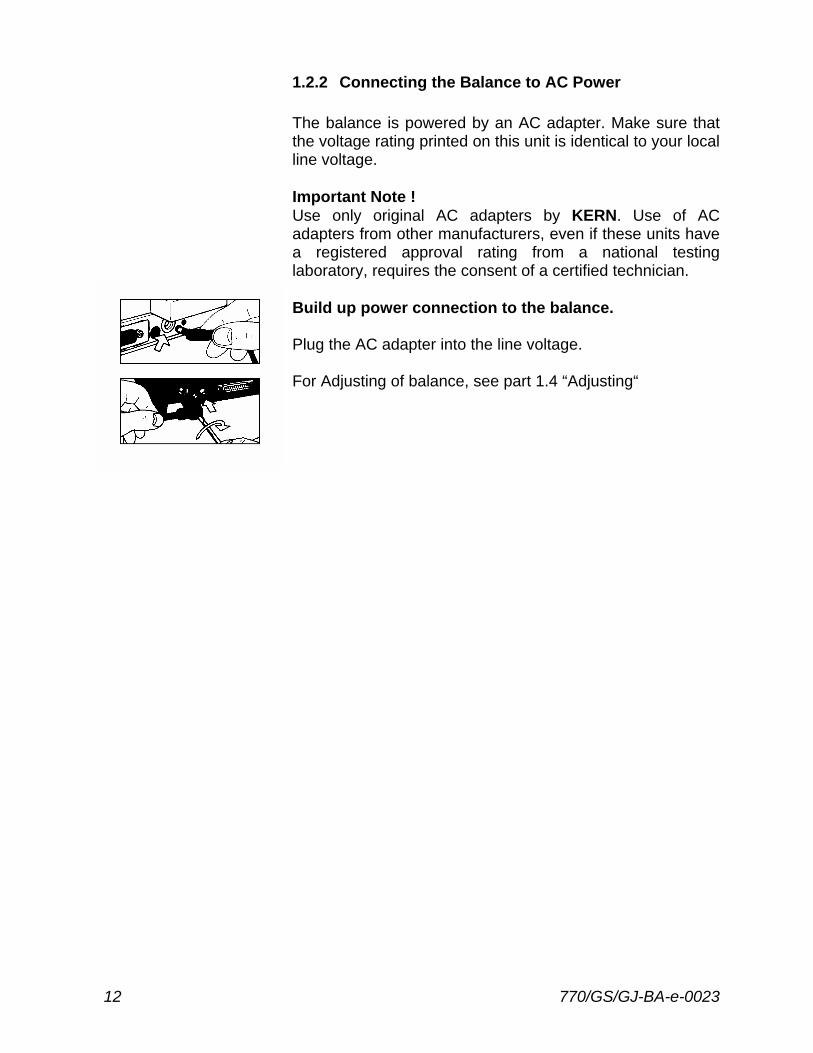
1.2.2 Connecting the Balance to AC Power The balance is powered by an AC adapter. Make sure that the voltage rating printed on this unit is identical to your local line voltage. Important Note ! Use only original AC adapters by KERN. Use of AC adapters from other manufacturers, even if these units have a registered approval rating from a national testing laboratory, requires the consent of a certified technician. Build up power connection to the balance. Plug the AC adapter into the line voltage. For Adjusting of balance, see part 1.4 “Adjusting“
770/GS/GJ-BA-e-0023 13
1.2.3 Safety Precautions The AC adapter rated to class 2 can be plugged into any wall outlet without requiring any additional safety precautions. The pole of the output voltage is connected to the balance housing, which can be grounded for operation. The data interface is also electrically connected to the balance housing (ground).
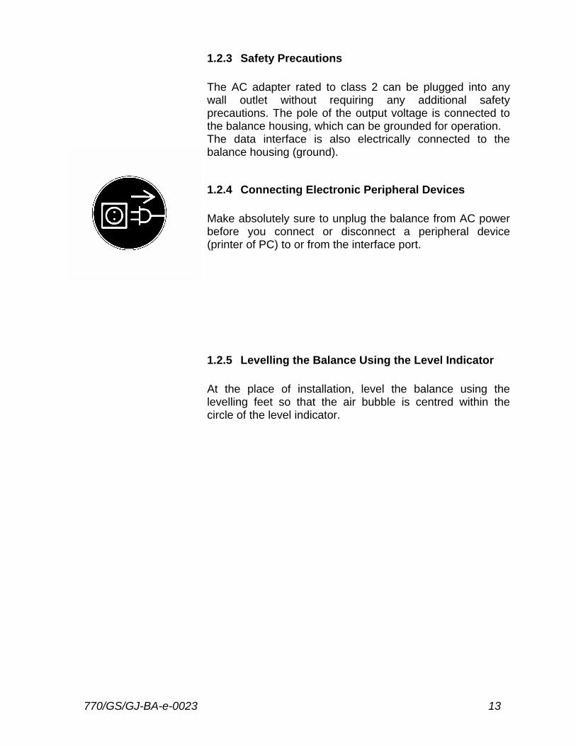
1.2.4 Connecting Electronic Peripheral Devices Make absolutely sure to unplug the balance from AC power before you connect or disconnect a peripheral device (printer of PC) to or from the interface port.
1.2.5 Levelling the Balance Using the Level Indicator At the place of installation, level the balance using the levelling feet so that the air bubble is centred within the circle of the level indicator.
14 770/GS/GJ-BA-e-0023
1.3 Operating the Balance
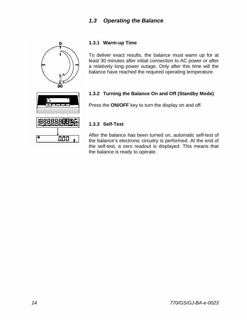
1.3.1 Warm-up Time To deliver exact results, the balance must warm up for at least 30 minutes after initial connection to AC power or after a relatively long power outage. Only after this time will the balance have reached the required operating temperature.
1.3.2 Turning the Balance On and Off (Standby Mode) Press the ON/OFF key to turn the display on and off.
1.3.3 Self-Test After the balance has been turned on, automatic self-test of the balance’s electronic circuitry is performed. At the end of the self-test, a zero readout is displayed. This means that the balance is ready to operate.
770/GS/GJ-BA-e-0023 15
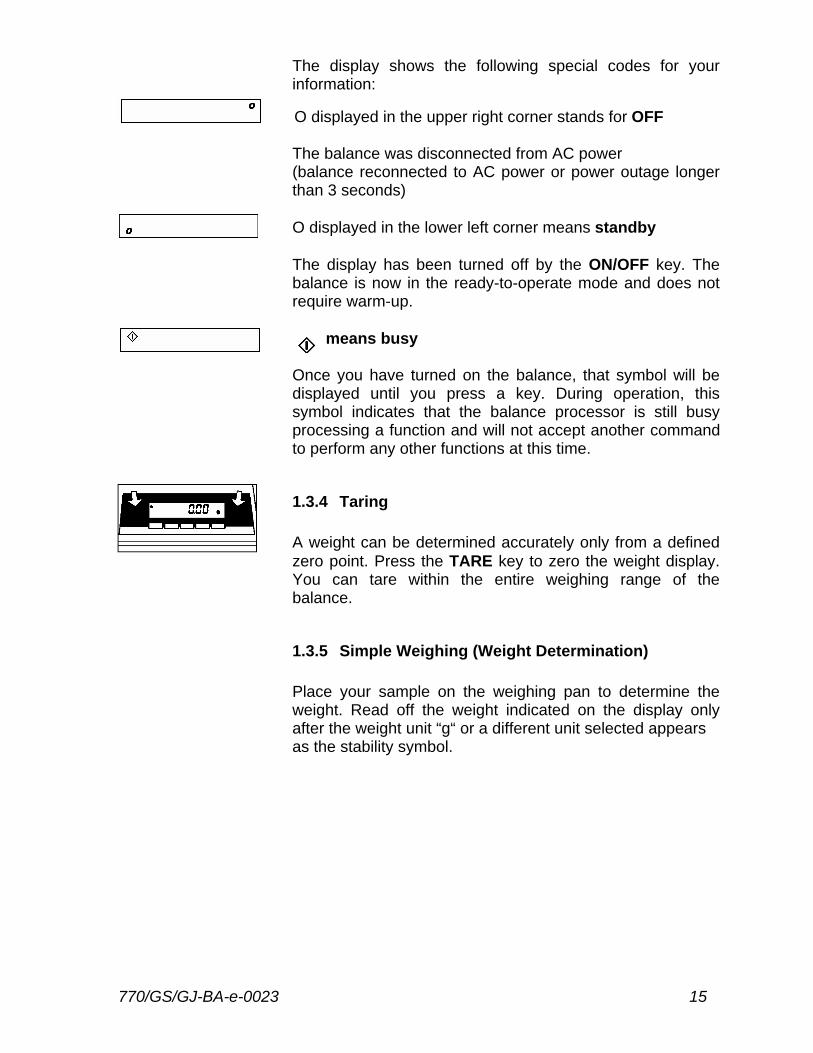
The display shows the following special codes for your information: O displayed in the upper right corner stands for OFF The balance was disconnected from AC power (balance reconnected to AC power or power outage longer than 3 seconds) O displayed in the lower left corner means standby The display has been turned off by the ON/OFF key. The balance is now in the ready-to-operate mode and does not require warm-up.
means busy
Once you have turned on the balance, that symbol will be displayed until you press a key. During operation, this symbol indicates that the balance processor is still busy processing a function and will not accept another command to perform any other functions at this time.
1.3.4 Taring A weight can be determined accurately only from a defined zero point. Press the TARE key to zero the weight display. You can tare within the entire weighing range of the balance.
1.3.5 Simple Weighing (Weight Determination) Place your sample on the weighing pan to determine the weight. Read off the weight indicated on the display only after the weight unit “g“ or a different unit selected appears as the stability symbol.
16 770/GS/GJ-BA-e-0023
1.4 Adjusting (formerly Calibration) During adjusting, the sensitivity of the balance is adjusted to changes in the ambient conditions. You must adjust your new balance at the place of installation after each warm-up period and before the first measurement. You must also readjust your balance each time you set it up in a different area or when the ambient conditions change (especially the temperature). The balance offers you various adjusting functions. You can select these functions by setting the appropriate menu codes. For more information, refer to part 2 “Balance Operating Menu“. Each adjusting function can be interrupted by pressing the CAL key .
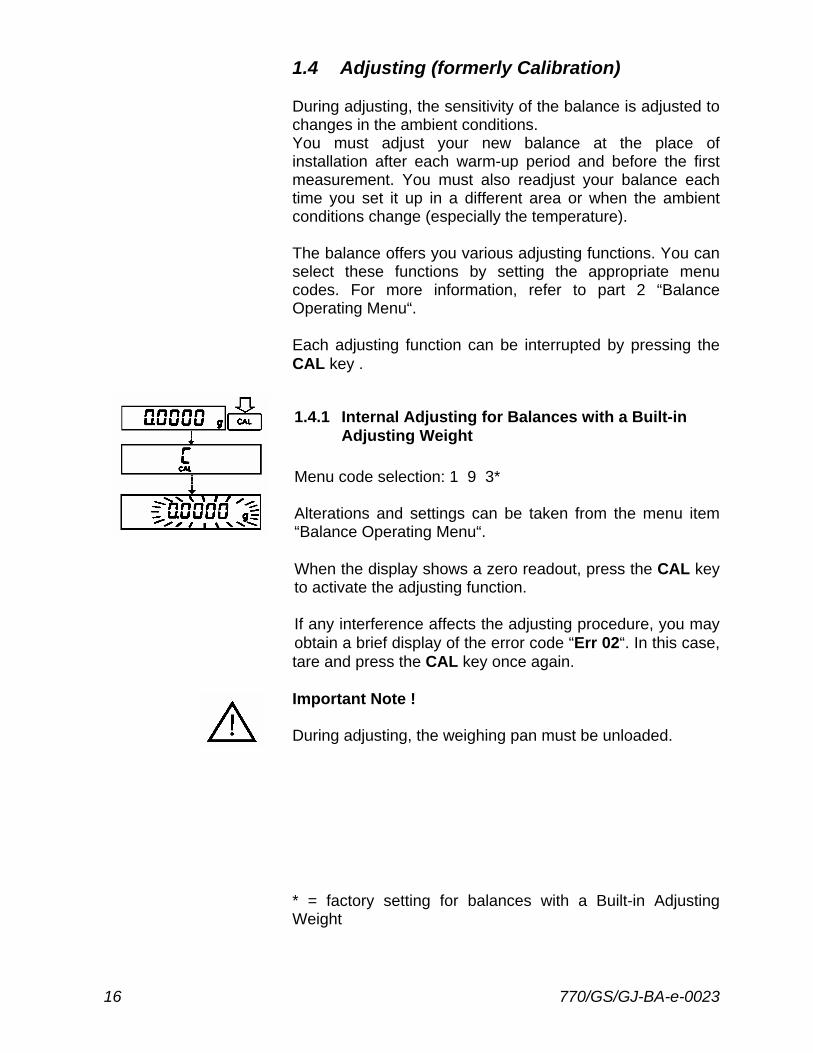
1.4.1 Internal Adjusting for Balances with a Built-in Adjusting Weight Menu code selection: 1 9 3* Alterations and settings can be taken from the menu item “Balance Operating Menu“. When the display shows a zero readout, press the CAL key to activate the adjusting function. If any interference affects the adjusting procedure, you may obtain a brief display of the error code “Err 02“. In this case, tare and press the CAL key once again. Important Note ! During adjusting, the weighing pan must be unloaded. * = factory setting for balances with a Built-in Adjusting Weight
770/GS/GJ-BA-e-0023 17
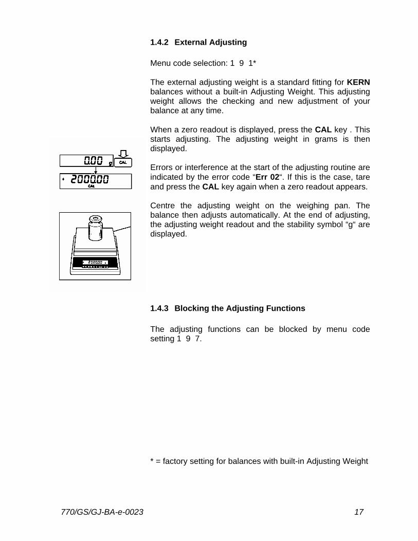
1.4.2 External Adjusting Menu code selection: 1 9 1* The external adjusting weight is a standard fitting for KERN balances without a built-in Adjusting Weight. This adjusting weight allows the checking and new adjustment of your balance at any time. When a zero readout is displayed, press the CAL key . This starts adjusting. The adjusting weight in grams is then displayed. Errors or interference at the start of the adjusting routine are indicated by the error code “Err 02“. If this is the case, tare and press the CAL key again when a zero readout appears. Centre the adjusting weight on the weighing pan. The balance then adjusts automatically. At the end of adjusting, the adjusting weight readout and the stability symbol “g“ are displayed.
1.4.3 Blocking the Adjusting Functions The adjusting functions can be blocked by menu code setting 1 9 7. * = factory setting for balances with built-in Adjusting Weight
18 770/GS/GJ-BA-e-0023
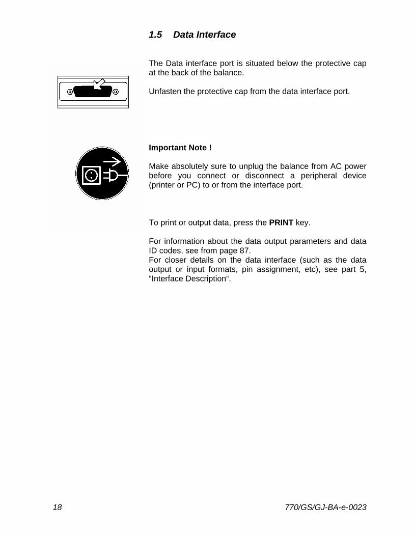
1.5 Data Interface The Data interface port is situated below the protective cap at the back of the balance. Unfasten the protective cap from the data interface port. Important Note ! Make absolutely sure to unplug the balance from AC power before you connect or disconnect a peripheral device (printer or PC) to or from the interface port. To print or output data, press the PRINT key. For information about the data output parameters and data ID codes, see from page 87. For closer details on the data interface (such as the data output or input formats, pin assignment, etc), see part 5, “Interface Description“.

770/GS/GJ-BA-e-0023 19
1.6 Below Balance Weighing A port for a below-balance weighing hanger is located on the bottom of the balance
To open the below-balance port, remove the cover plate from the bottom of the balance. To hook a sample on the hanger, open the below-balance port by removing the cover plate.
Important Note ! When you use below-balance weighing hangers, you must install a shield for protection against drafts.
1.7 Anti-theft Locking Device To fasten an anti-theft locking device, use the lug located on the rear panel of the balance.
20 770/GS/GJ-BA-e-0023
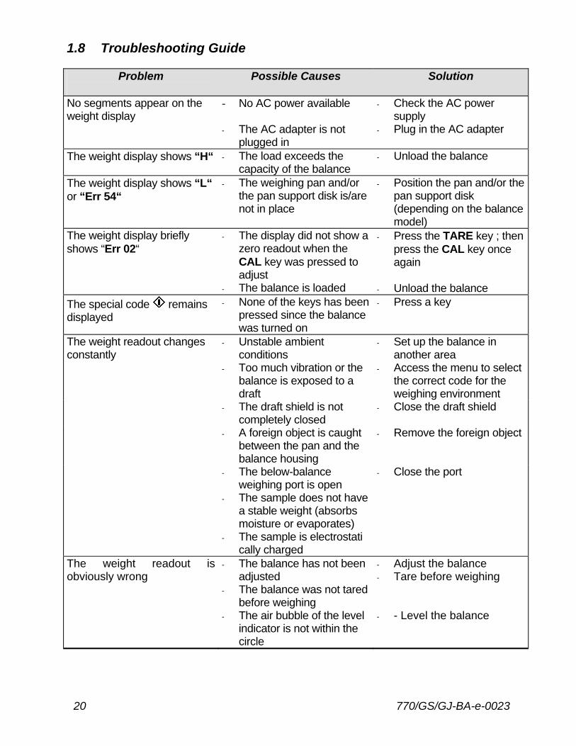
1.8 Troubleshooting Guide
Problem
Possible Causes Solution
No segments appear on the weight display
- No AC power available
- The AC adapter is not plugged in
- Check the AC power supply
- Plug in the AC adapter
The weight display shows “H“ - The load exceeds the capacity of the balance
- Unload the balance
The weight display shows “L“ or “Err 54“
- The weighing pan and/or the pan support disk is/are not in place
- Position the pan and/or the pan support disk (depending on the balance model)
The weight display briefly shows “Err 02“
- The display did not show a zero readout when the CAL key was pressed to adjust
- The balance is loaded
- Press the TARE key ; then press the CAL key once again
- Unload the balance
The special code remains displayed
- None of the keys has been pressed since the balance was turned on
- Press a key
The weight readout changes constantly
- Unstable ambient conditions
- Too much vibration or the balance is exposed to a draft
- Set up the balance in another area
- Access the menu to select the correct code for the weighing environment
- The draft shield is not completely closed
- Close the draft shield
- A foreign object is caught between the pan and the balance housing
- Remove the foreign object
- The below-balance weighing port is open
- Close the port
- The sample does not have a stable weight (absorbs moisture or evaporates)
- The sample is electrostati cally charged
The weight readout is obviously wrong
- The balance has not been adjusted
- The balance was not tared before weighing
- The air bubble of the level indicator is not within the circle
- Adjust the balance - Tare before weighing - - Level the balance
770/GS/GJ-BA-e-0023 21
1.9 Care and Maintenance
1.9.1 Cleaning Before cleaning the balance, unplug the AC adapter from the wall outlet. Please do not use any aggressive cleaning agents (solvents or similar agents). Instead, use a piece of cloth which has been wet with a mild detergent (soap). Make sure that no liquid enters the balance housing. After cleaning, wipe down the balance with a soft, dry piece of cloth. Carefully remove any sample residue/spilled powder by using a brush or a hand-held vacuum cleaner.
1.9.2 Safety Inspection If there is any indication that safe operation of the balance with the AC adapter is no longer guaranteed, turn off the power and disconnect the equipment in a secure place to ensure that it cannot be used for the time being. Safe operation of the balance with the AC adapter is no longer ensured when - there is visible damage to the AC adapter; - the AC adapter no longer functions properly; - the AC adapter has been stored for a relatively long
period under unfavourable conditions. In this case, notify your nearest supplier. Only service technicians who have access to the required maintenance manuals are allowed to perform maintenance and repairwork on the equipment. The electrical and electronic components used in the balance are rated to at least Class KSF according to DIN 40040.
22 770/GS/GJ-BA-e-0023
2 Declarations of conformity
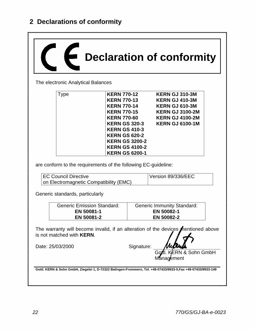
Declaration of conformity
The electronic Analytical Balances Type KERN 770-12
KERN 770-13 KERN 770-14 KERN 770-15 KERN 770-60 KERN GS 320-3 KERN GS 410-3 KERN GS 620-2 KERN GS 3200-2 KERN GS 4100-2 KERN GS 6200-1
KERN GJ 310-3M KERN GJ 410-3M KERN GJ 610-3M KERN GJ 3100-2M KERN GJ 4100-2M KERN GJ 6100-1M
are conform to the requirements of the following EC-guideline: EC Council Directive
on Electromagnetic Compatibility (EMC) Version 89/336/EEC
Generic standards, particularly Generic Emission Standard:
EN 50081-1 EN 50081-2
Generic Immunity Standard: EN 50082-1 EN 50082-2
The warranty will become invalid, if an alteration of the devices mentioned above
is not matched with KERN.
Date: 25/03/2000 Signature: Gottl. KERN & Sohn GmbH Management Gottl. KERN & Sohn GmbH, Ziegelei 1, D-72322 Balingen-Frommern, Tel. +49-07433/9933-0,Fax +49-07433/9933-149
770/GS/GJ-BA-e-0023 23
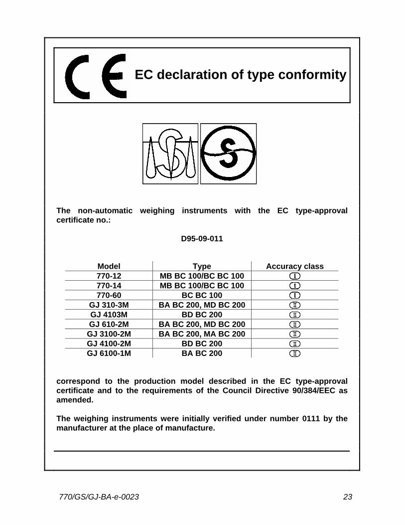
EC declaration of type conformity
The non-automatic weighing instruments with the EC type-approval
certificate no.:
D95-09-011 Model Type Accuracy class 770-12 MB BC 100/BC BC 100 770-14 MB BC 100/BC BC 100 770-60 BC BC 100 GJ 310-3M BA BC 200, MD BC 200 GJ 4103M BD BC 200 GJ 610-2M BA BC 200, MD BC 200 GJ 3100-2M BA BC 200, MA BC 200 GJ 4100-2M BD BC 200 GJ 6100-1M BA BC 200 correspond to the production model described in the EC type-approval
certificate and to the requirements of the Council Directive 90/384/EEC as amended.
The weighing instruments were initially verified under number 0111 by the
manufacturer at the place of manufacture.
24 770/GS/GJ-BA-e-0023
3 Balance Operating Menu In the operating menu, you can define how your balance will adapt to ambient conditions and also how it will work to meet your special requirements. For your convenience, the menu codes have been factory-set so that you do not have to make any changes, as a rule. If you have special operating conditions, adjust the balance to your requirements by setting the menu codes of your choice. The factory-set menu codes are identified by an “*“ in this instruction manual. You can select the functions not identified by an “*“ by setting the respective menu codes. You will find these codes in the section entitled “Balance Operating Parameters“. If you need to change any of the factory settings, we recommend that you enter these changes along with the date in the column headed by “Changes“.
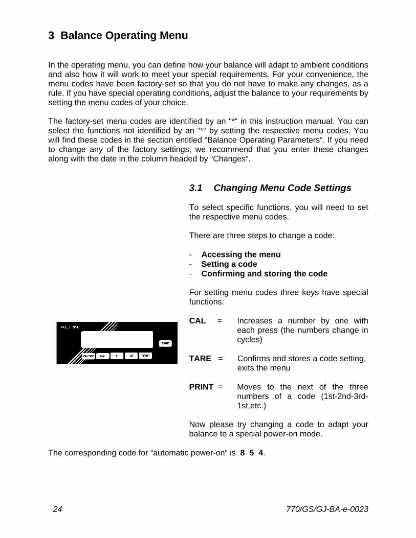
3.1 Changing Menu Code Settings To select specific functions, you will need to set the respective menu codes. There are three steps to change a code: - Accessing the menu - Setting a code - Confirming and storing the code For setting menu codes three keys have special functions: CAL = Increases a number by one with
each press (the numbers change in cycles)
TARE = Confirms and stores a code setting,
exits the menu PRINT = Moves to the next of the three
numbers of a code (1st-2nd-3rd-1st,etc.)
Now please try changing a code to adapt your balance to a special power-on mode.
The corresponding code for “automatic power-on“ is 8 5 4.
770/GS/GJ-BA-e-0023 25
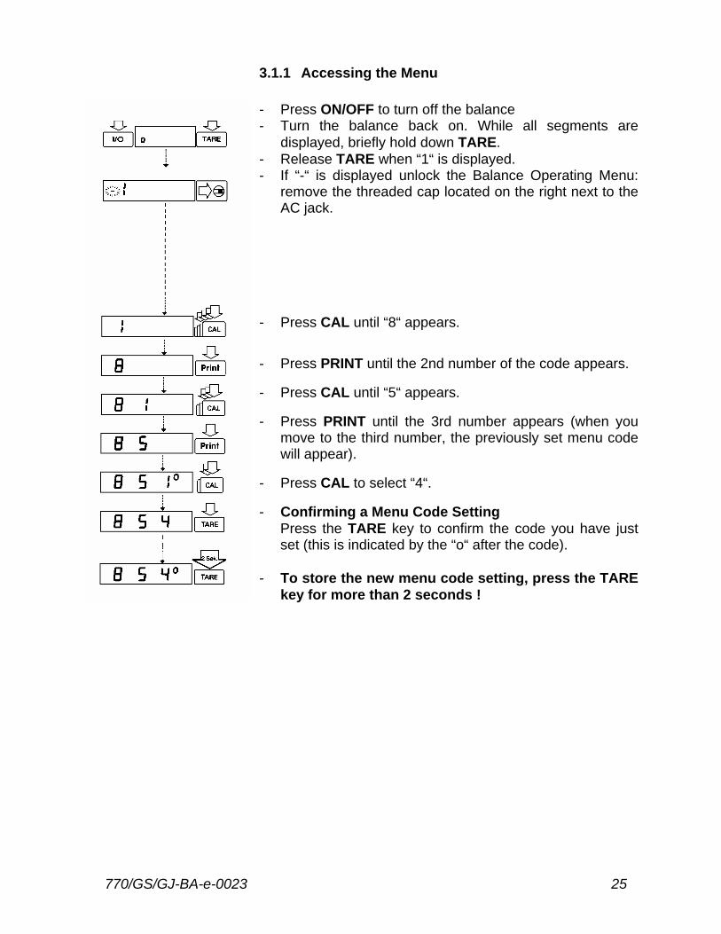
3.1.1 Accessing the Menu - Press ON/OFF to turn off the balance - Turn the balance back on. While all segments are
displayed, briefly hold down TARE. - Release TARE when “1“ is displayed. - If “-“ is displayed unlock the Balance Operating Menu:
remove the threaded cap located on the right next to the AC jack.
- Press CAL until “8“ appears. - Press PRINT until the 2nd number of the code appears. - Press CAL until “5“ appears. - Press PRINT until the 3rd number appears (when you
move to the third number, the previously set menu code will appear).
- Press CAL to select “4“. - Confirming a Menu Code Setting
Press the TARE key to confirm the code you have just set (this is indicated by the “o“ after the code).
- To store the new menu code setting, press the TARE
key for more than 2 seconds !
26 770/GS/GJ-BA-e-0023
The current code setting in the balance operating menu is identified by a small, superscript “o“ after the last number. When you access the operating menu, the previously set code will be displayed after you have selected the right-hand number, which means the entire menu code setting will be displayed. This makes it easy for you to check the previously set menu codes. If you would like to change several menu code settings, you do not have to press the TARE key after each change to exit the balance operating menu. You can also confirm individual settings. Important Note ! By turning of the access switch an accidental alteration of the menu settings can be avoided. You can make this setting anytime you wish once you have accessed it. However, it is best if you wait to lock the menu until you have changed the last code setting. Leaving the Menu without Storing Changes to the Code Settings Changes to the code settings are not stored if you turn off the balance by pressing the ON/OFF key while changing the settings and before saving them.
3.1.2 Reset Function - Undoing All Menu Code Changes The reset function enables you to undo all menu code changes, which means that you will obtain the original factory-set menu codes identified by an “*“. To use this function, select code 9--1 . See the previous page for information on confirming and storing a menu code setting.
770/GS/GJ-BA-e-0023 27
3.2 Balance Operating Parameters
3.2.1 Adapting the Balance to Ambient Conditions The balance can be adapted to the prevailing ambient conditions at the place of installation. Code very stable conditions 1 1 1 stable conditions 1 1 2* unstable conditions 1 1 3 very unstable conditions 1 1 4
3.2.2 Standard Weighing Mode - Manual Filling Mode You can optimally adapt your balance to meet either of these requirements. In the manual filling mode, the display compensates for fluctuations of the load on the balance, giving you especially fast and stable readouts. Code standard weighing mode 1 2 1* manual filling mode 1 2 2
3.2.3 Stability Range The stability symbol will remain displayed in the case of a weight variation +/-
Code
0,25 digit 1 3 1 0,5 digit 1 3 2 1 digit 1 3 3 2 digits 1 3 4* 4 digits 1 3 5 8 digits 1 3 6 * = factory setting; depends on the balance model in some cases
28 770/GS/GJ-BA-e-0023
3.2.4 Tare Parameter You can define when the balance will perform the taring operation: Code at any time 1 5 1 not until the readout is stable 1 5 2*
3.2.5 Auto Zero Function When this function is activated, any slight changes of the zero readout are automatically tared. Code Auto Zero on 1 6 1* Auto Zero off 1 6 2
3.2.6 Adjusting and Linearisation Functions Using CAL Code external adjusting 1 9 1* internal adjusting for balance models with a built-in automatic adjusting weight
external linearisation 1 9 5 adjusting functions blocked 1 9 7 * = factory setting; depends on the balance model in some cases
770/GS/GJ-BA-e-0023 29
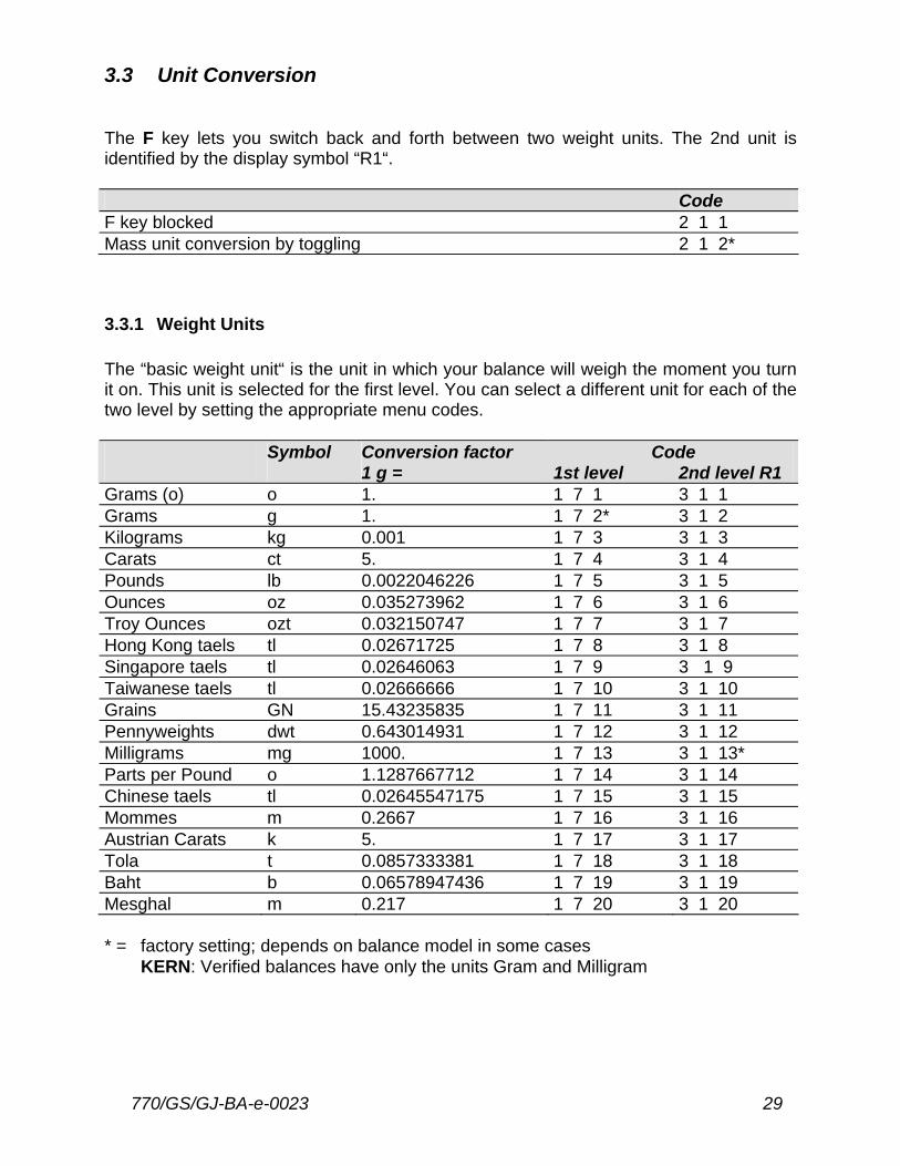
3.3 Unit Conversion The F key lets you switch back and forth between two weight units. The 2nd unit is identified by the display symbol “R1“. Code F key blocked 2 1 1 Mass unit conversion by toggling 2 1 2*
3.3.1 Weight Units The “basic weight unit“ is the unit in which your balance will weigh the moment you turn it on. This unit is selected for the first level. You can select a different unit for each of the two level by setting the appropriate menu codes. Symbol Conversion factor Code 1 g = 1st level 2nd level R1 Grams (o) o 1. 1 7 1 3 1 1 Grams g 1. 1 7 2* 3 1 2 Kilograms kg 0.001 1 7 3 3 1 3 Carats ct 5. 1 7 4 3 1 4 Pounds lb 0.0022046226 1 7 5 3 1 5 Ounces oz 0.035273962 1 7 6 3 1 6 Troy Ounces ozt 0.032150747 1 7 7 3 1 7 Hong Kong taels tl 0.02671725 1 7 8 3 1 8 Singapore taels tl 0.02646063 1 7 9 3 1 9 Taiwanese taels tl 0.02666666 1 7 10 3 1 10 Grains GN 15.43235835 1 7 11 3 1 11 Pennyweights dwt 0.643014931 1 7 12 3 1 12 Milligrams mg 1000. 1 7 13 3 1 13* Parts per Pound o 1.1287667712 1 7 14 3 1 14 Chinese taels tl 0.02645547175 1 7 15 3 1 15 Mommes m 0.2667 1 7 16 3 1 16 Austrian Carats k 5. 1 7 17 3 1 17 Tola t 0.0857333381 1 7 18 3 1 18 Baht b 0.06578947436 1 7 19 3 1 19 Mesghal m 0.217 1 7 20 3 1 20 * = factory setting; depends on balance model in some cases
KERN: Verified balances have only the units Gram and Milligram
30 770/GS/GJ-BA-e-0023
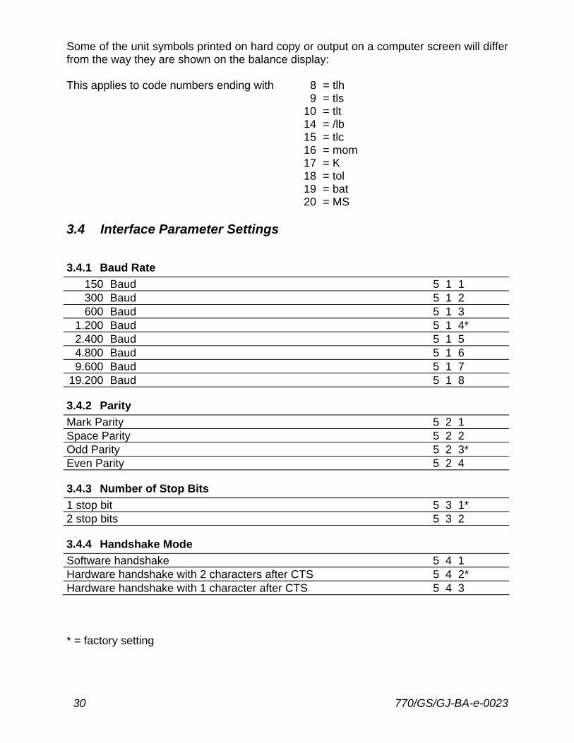
Some of the unit symbols printed on hard copy or output on a computer screen will differ from the way they are shown on the balance display: This applies to code numbers ending with 8 = tlh 9 = tls 10 = tlt 14 = /lb 15 = tlc 16 = mom 17 = K 18 = tol 19 = bat 20 = MS 3.4 Interface Parameter Settings
3.4.1 Baud Rate 150 Baud 5 1 1 300 Baud 5 1 2 600 Baud 5 1 3
1.200 Baud 5 1 4* 2.400 Baud 5 1 5 4.800 Baud 5 1 6 9.600 Baud 5 1 7
19.200 Baud 5 1 8
3.4.2 Parity
Mark Parity 5 2 1 Space Parity 5 2 2 Odd Parity 5 2 3* Even Parity 5 2 4
3.4.3 Number of Stop Bits
1 stop bit 5 3 1* 2 stop bits 5 3 2
3.4.4 Handshake Mode
Software handshake 5 4 1 Hardware handshake with 2 characters after CTS 5 4 2* Hardware handshake with 1 character after CTS 5 4 3 * = factory setting
770/GS/GJ-BA-e-0023 31
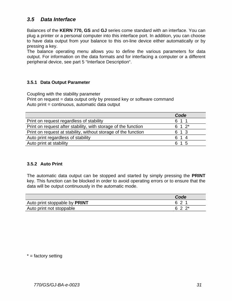
3.5 Data Interface Balances of the KERN 770, GS and GJ series come standard with an interface. You can plug a printer or a personal computer into this interface port. In addition, you can choose to have data output from your balance to this on-line device either automatically or by pressing a key. The balance operating menu allows you to define the various parameters for data output. For information on the data formats and for interfacing a computer or a different peripheral device, see part 5 “Interface Description“.
3.5.1 Data Output Parameter Coupling with the stability parameter Print on request = data output only by pressed key or software command Auto print = continuous, automatic data output Code Print on request regardless of stability 6 1 1 Print on request after stability, with storage of the function 6 1 2* Print on request at stability, without storage of the function 6 1 3 Auto print regardless of stability 6 1 4 Auto print at stability 6 1 5
3.5.2 Auto Print The automatic data output can be stopped and started by simply pressing the PRINT key. This function can be blocked in order to avoid operating errors or to ensure that the data will be output continuously in the automatic mode. Code Auto print stoppable by PRINT 6 2 1 Auto print not stoppable 6 2 2* * = factory setting
32 770/GS/GJ-BA-e-0023
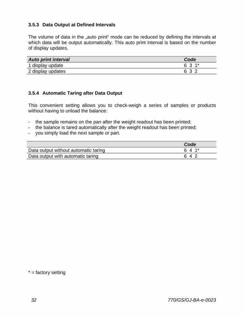
3.5.3 Data Output at Defined Intervals The volume of data in the „auto print“ mode can be reduced by defining the intervals at which data will be output automatically. This auto print interval is based on the number of display updates. Auto print interval Code 1 display update 6 3 1* 2 display updates 6 3 2
3.5.4 Automatic Taring after Data Output This convenient setting allows you to check-weigh a series of samples or products without having to unload the balance: - the sample remains on the pan after the weight readout has been printed; - the balance is tared automatically after the weight readout has been printed; - you simply load the next sample or part. Code Data output without automatic taring 6 4 1* Data output with automatic taring 6 4 2 * = factory setting
770/GS/GJ-BA-e-0023 33
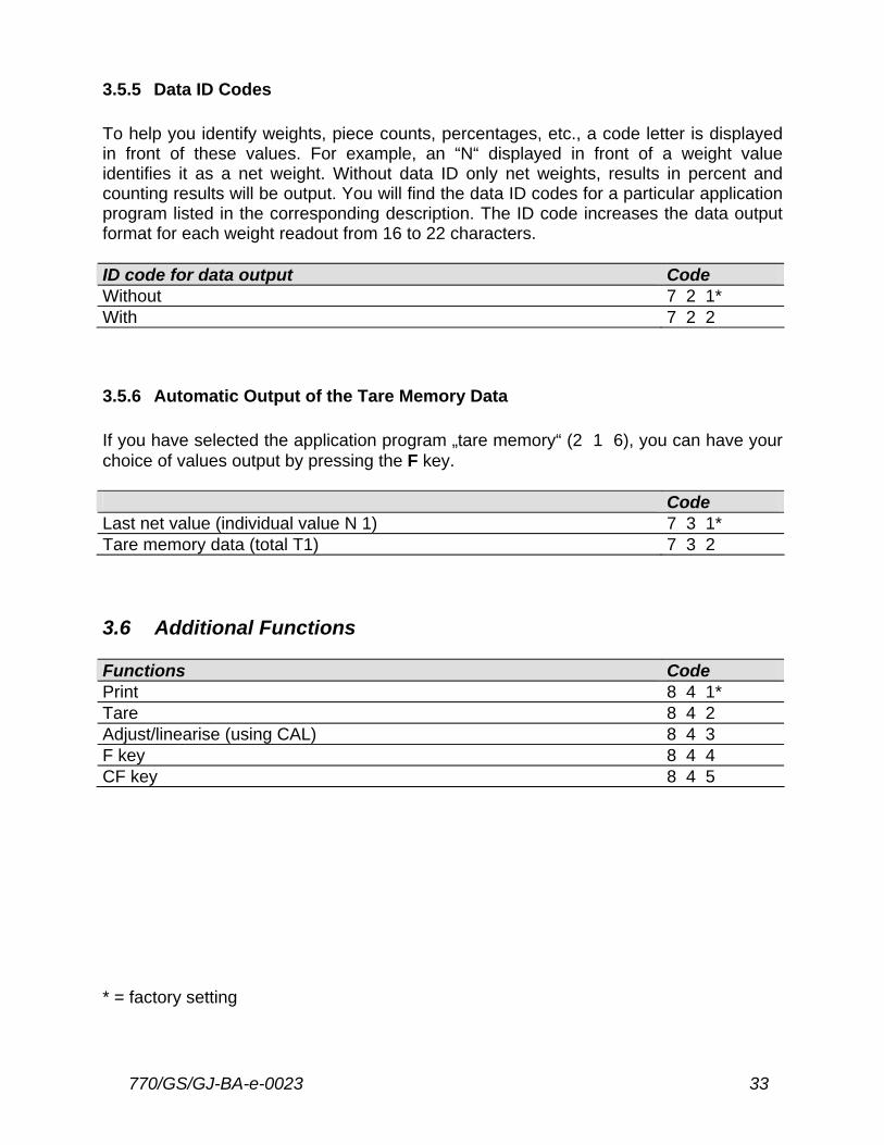
3.5.5 Data ID Codes To help you identify weights, piece counts, percentages, etc., a code letter is displayed in front of these values. For example, an “N“ displayed in front of a weight value identifies it as a net weight. Without data ID only net weights, results in percent and counting results will be output. You will find the data ID codes for a particular application program listed in the corresponding description. The ID code increases the data output format for each weight readout from 16 to 22 characters. ID code for data output Code Without 7 2 1* With 7 2 2
3.5.6 Automatic Output of the Tare Memory Data If you have selected the application program „tare memory“ (2 1 6), you can have your choice of values output by pressing the F key. Code Last net value (individual value N 1) 7 3 1* Tare memory data (total T1) 7 3 2 3.6 Additional Functions Functions Code Print 8 4 1* Tare 8 4 2 Adjust/linearise (using CAL) 8 4 3 F key 8 4 4 CF key 8 4 5 * = factory setting
34 770/GS/GJ-BA-e-0023
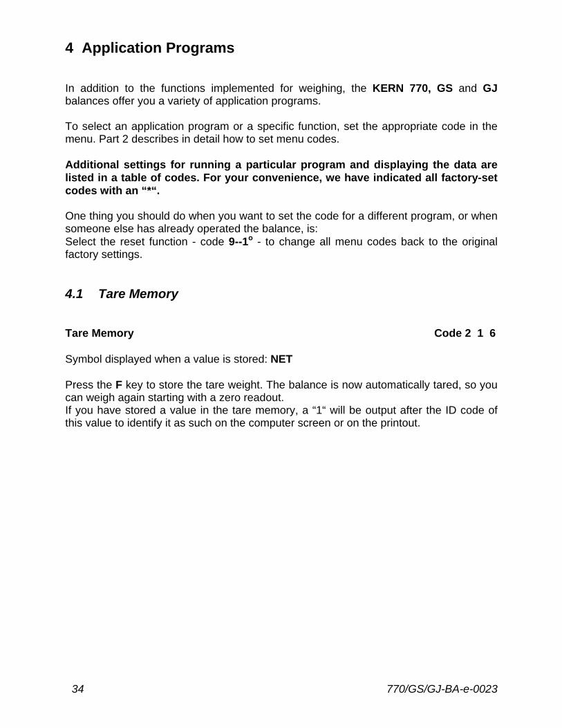
4 Application Programs In addition to the functions implemented for weighing, the KERN 770, GS and GJ balances offer you a variety of application programs. To select an application program or a specific function, set the appropriate code in the menu. Part 2 describes in detail how to set menu codes. Additional settings for running a particular program and displaying the data are listed in a table of codes. For your convenience, we have indicated all factory-set codes with an “*“. One thing you should do when you want to set the code for a different program, or when someone else has already operated the balance, is: Select the reset function - code 9--1o - to change all menu codes back to the original factory settings. 4.1 Tare Memory Tare Memory Code 2 1 6 Symbol displayed when a value is stored: NET Press the F key to store the tare weight. The balance is now automatically tared, so you can weigh again starting with a zero readout. If you have stored a value in the tare memory, a “1“ will be output after the ID code of this value to identify it as such on the computer screen or on the printout.
770/GS/GJ-BA-e-0023 35
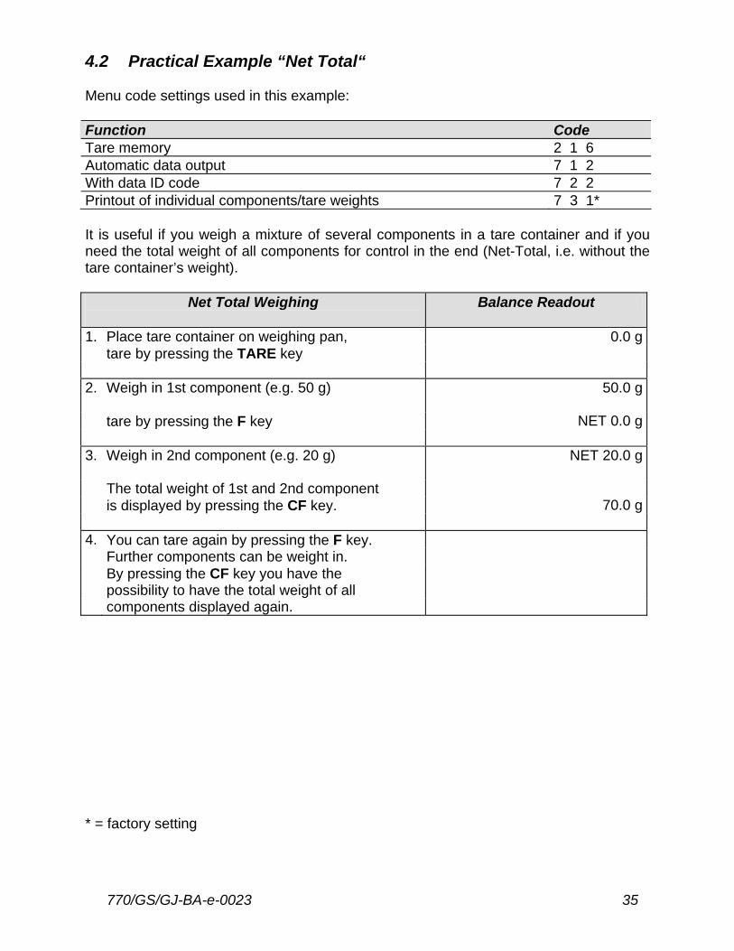
4.2 Practical Example “Net Total“ Menu code settings used in this example: Function Code Tare memory 2 1 6 Automatic data output 7 1 2 With data ID code 7 2 2 Printout of individual components/tare weights 7 3 1* It is useful if you weigh a mixture of several components in a tare container and if you need the total weight of all components for control in the end (Net-Total, i.e. without the tare container’s weight).
Net Total Weighing
Balance Readout
1. Place tare container on weighing pan, 0.0 g tare by pressing the TARE key 2. Weigh in 1st component (e.g. 50 g) 50.0 g tare by pressing the F key NET 0.0 g 3. Weigh in 2nd component (e.g. 20 g) NET 20.0 g The total weight of 1st and 2nd component is displayed by pressing the CF key. 70.0 g 4. You can tare again by pressing the F key. Further components can be weight in. By pressing the CF key you have the possibility to have the total weight of all components displayed again. * = factory setting
36 770/GS/GJ-BA-e-0023
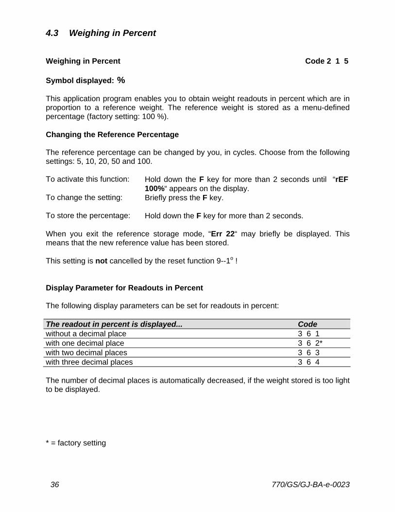
4.3 Weighing in Percent Weighing in Percent Code 2 1 5 Symbol displayed: % This application program enables you to obtain weight readouts in percent which are in proportion to a reference weight. The reference weight is stored as a menu-defined percentage (factory setting: 100 %). Changing the Reference Percentage The reference percentage can be changed by you, in cycles. Choose from the following settings: 5, 10, 20, 50 and 100. To activate this function: Hold down the F key for more than 2 seconds until “rEF
100%“ appears on the display. To change the setting: Briefly press the F key.
To store the percentage: Hold down the F key for more than 2 seconds. When you exit the reference storage mode, “Err 22“ may briefly be displayed. This means that the new reference value has been stored. This setting is not cancelled by the reset function 9--1o ! Display Parameter for Readouts in Percent The following display parameters can be set for readouts in percent: The readout in percent is displayed... Code without a decimal place 3 6 1 with one decimal place 3 6 2* with two decimal places 3 6 3 with three decimal places 3 6 4 The number of decimal places is automatically decreased, if the weight stored is too light to be displayed. * = factory setting
770/GS/GJ-BA-e-0023 37
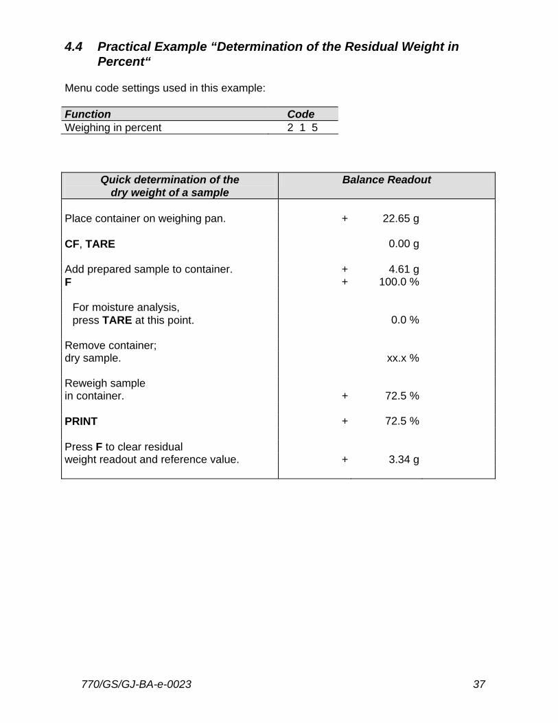
4.4 Practical Example “Determination of the Residual Weight in Percent“ Menu code settings used in this example: Function Code Weighing in percent 2 1 5
Quick determination of the dry weight of a sample
Balance Readout
Place container on weighing pan. + 22.65 g CF, TARE 0.00 g Add prepared sample to container. + 4.61 g F + 100.0 %
For moisture analysis, press TARE at this point. 0.0 %
Remove container; dry sample. xx.x % Reweigh sample in container. + 72.5 % PRINT + 72.5 % Press F to clear residual weight readout and reference value. + 3.34 g
38 770/GS/GJ-BA-e-0023
4.5 Counting Counting Code 2 1 4 Symbol displayed: The counting program allows automatic conversion of weights into piece counts based on a reference sample weight. A weight readout is stored as a reference quantity (factory setting: 10 pcs = pieces). Displaying the Reference Sample Quantity If the weighing pan is unloaded, the set reference sample quantity (pcs) briefly appears in the weight display after having pressed the F key. Changing the Reference Sample Quantity The reference sample quantity can be changed in cycles, by you. Choose from the following settings: 5, 10, 20, 50 and 100. To activate this function: Hold down the F key for more than 2 seconds until “rEF ...
pcs“ appears on the display. To change the setting: Briefly press the F key.
To store the quantity: Hold down the F key for more than 2 seconds. When you exit the reference storage mode, “Err 22“ may briefly be displayed. This means that the new reference value has been stored. This setting is not cancelled by the reset function 9--1o ! Toggling between the Piece Count (pcs) and Weight (g) After placing the sample on the weighing pan, you can toggle between the piece count and the respective weight readout by pressing the F key.

770/GS/GJ-BA-e-0023 39
4.6 Practical Example “Counting Small Parts“ Menu code settings used in this example: Function Code Counting 2 1 4
Counting bulk quantities of items with the same weight
Balance Readout
Place container on weighing pan. + 22.65 g CF, TARE 0.00 g Add 10 counted parts. Confirm reference sample quantity by F. + 10 pcs Fill container with desired quantity of parts + 500 pcs Press F to clear the weight readout and the reference value. + 2827.35 g
40 770/GS/GJ-BA-e-0023
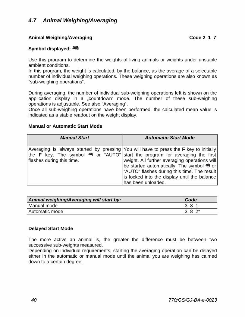
4.7 Animal Weighing/Averaging Animal Weighing/Averaging Code 2 1 7 Symbol displayed: Use this program to determine the weights of living animals or weights under unstable ambient conditions. In this program, the weight is calculated, by the balance, as the average of a selectable number of individual weighing operations. These weighing operations are also known as “sub-weighing operations“. During averaging, the number of individual sub-weighing operations left is shown on the application display in a „countdown“ mode. The number of these sub-weighing operations is adjustable. See also “Averaging“. Once all sub-weighing operations have been performed, the calculated mean value is indicated as a stable readout on the weight display. Manual or Automatic Start Mode
Manual Start
Automatic Start Mode
Averaging is always started by pressing the F key. The symbol or “AUTO“ flashes during this time.
You will have to press the F key to initially start the program for averaging the first weight. All further averaging operations will be started automatically. The symbol or “AUTO“ flashes during this time. The result is locked into the display until the balance has been unloaded.
Animal weighing/Averaging will start by: Code Manual mode 3 8 1 Automatic mode 3 8 2* Delayed Start Mode The more active an animal is, the greater the difference must be between two successive sub-weights measured. Depending on individual requirements, starting the averaging operation can be delayed either in the automatic or manual mode until the animal you are weighing has calmed down to a certain degree.
770/GS/GJ-BA-e-0023 41
In this case, the start criterion is defined by the difference between two successive sub-weights measured. If the animal moves, the start criterion is not met; therefore, averaging will not start. Once the animal has calmed down, the program checks whether two measured sub-weights are within the previously selected range. If so, the actual averaging operation will be started. Delay start until... Code difference is slight 3 7 1 difference is average 3 7 2* difference is considerable 3 7 3 During averaging, the number of sub-weighing operations left to perform is shown on the weight display (countdown mode). Changing the Number of Sub-weighing Operations The number of sub-weighing operations used to average a weight can be changed in cycles, by you. You can choose from the following settings: 5, 10, 20, 50 and 100. To activate this function: Hold down the F key for more than 2 seconds until “rEF
10“ appears on the display. To change the setting: Briefly press the F key.
To store the number: Hold down the F key for more than 2 seconds. This setting is not cancelled by the reset function 9--1o ! Note To obtain an added measure of reliability in the automatic mode in order to avoid an “incorrect start“, a weight value must correspond to a minimum load of 100 display increments. Once averaging has been completed, the program will stop until the balance is unloaded to half the value (50 display increments) of the storage threshold.
42 770/GS/GJ-BA-e-0023
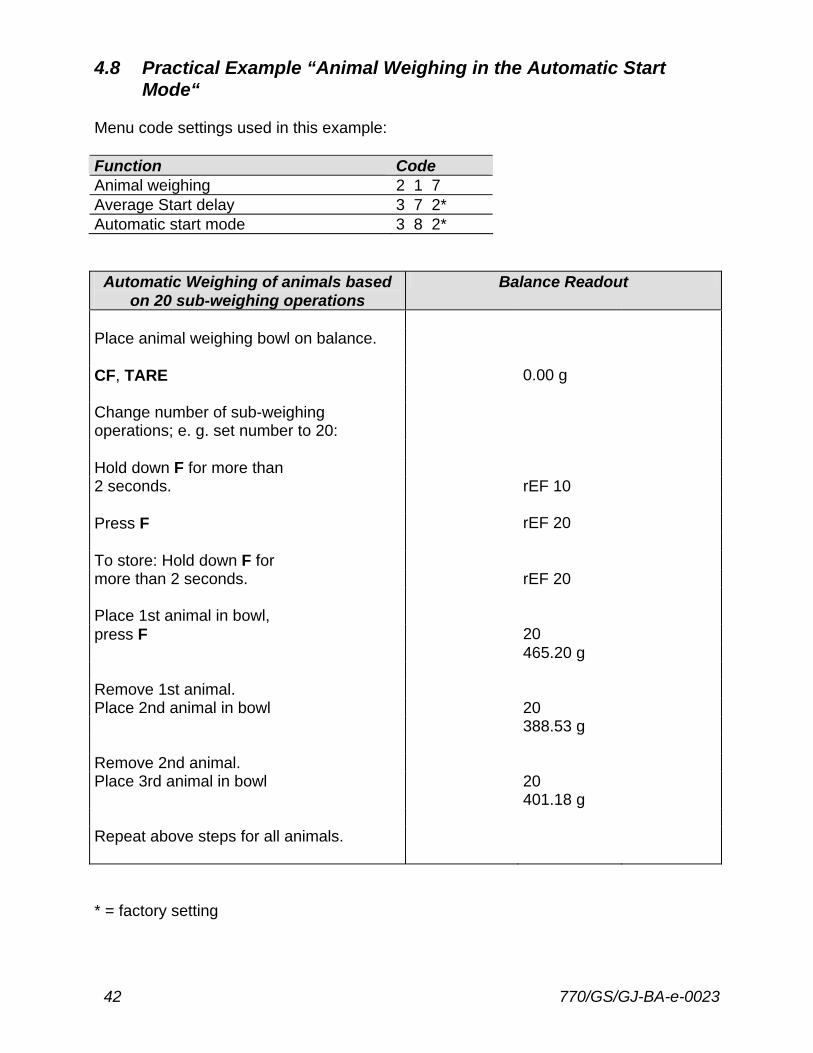
4.8 Practical Example “Animal Weighing in the Automatic Start Mode“ Menu code settings used in this example: Function Code Animal weighing 2 1 7 Average Start delay 3 7 2* Automatic start mode 3 8 2*
Automatic Weighing of animals based on 20 sub-weighing operations
Balance Readout
Place animal weighing bowl on balance. CF, TARE 0.00 g Change number of sub-weighing operations; e. g. set number to 20: Hold down F for more than 2 seconds. rEF 10 Press F rEF 20 To store: Hold down F for more than 2 seconds. rEF 20 Place 1st animal in bowl, press F 20 465.20 g Remove 1st animal. Place 2nd animal in bowl 20 388.53 g Remove 2nd animal. Place 3rd animal in bowl 20 401.18 g Repeat above steps for all animals. * = factory setting
770/GS/GJ-BA-e-0023 43
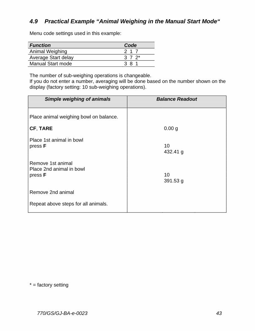
4.9 Practical Example “Animal Weighing in the Manual Start Mode“ Menu code settings used in this example: Function Code Animal Weighing 2 1 7 Average Start delay 3 7 2* Manual Start mode 3 8 1 The number of sub-weighing operations is changeable. If you do not enter a number, averaging will be done based on the number shown on the display (factory setting: 10 sub-weighing operations).
Simple weighing of animals Balance Readout
Place animal weighing bowl on balance. CF, TARE 0.00 g Place 1st animal in bowl press F 10 432.41 g Remove 1st animal Place 2nd animal in bowl press F 10 391.53 g Remove 2nd animal Repeat above steps for all animals. * = factory setting
44 770/GS/GJ-BA-e-0023
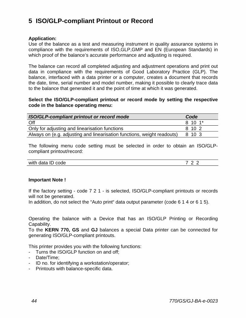
5 ISO/GLP-compliant Printout or Record Application: Use of the balance as a test and measuring instrument in quality assurance systems in compliance with the requirements of ISO,GLP,GMP and EN (European Standards) in which proof of the balance’s accurate performance and adjusting is required. The balance can record all completed adjusting and adjustment operations and print out data in compliance with the requirements of Good Laboratory Practice (GLP). The balance, interfaced with a data printer or a computer, creates a document that records the date, time, serial number and model number, making it possible to clearly trace data to the balance that generated it and the point of time at which it was generated. Select the ISO/GLP-compliant printout or record mode by setting the respective code in the balance operating menu: ISO/GLP-compliant printout or record mode Code Off 8 10 1* Only for adjusting and linearisation functions 8 10 2 Always on (e.g. adjusting and linearisation functions, weight readouts) 8 10 3 The following menu code setting must be selected in order to obtain an ISO/GLP-compliant printout/record: with data ID code 7 2 2 Important Note ! If the factory setting - code 7 2 1 - is selected, ISO/GLP-compliant printouts or records will not be generated. In addition, do not select the “Auto print“ data output parameter (code 6 1 4 or 6 1 5). Operating the balance with a Device that has an ISO/GLP Printing or Recording Capability. To the KERN 770, GS and GJ balances a special Data printer can be connected for generating ISO/GLP-compliant printouts. This printer provides you with the following functions: - Turns the ISO/GLP function on and off; - Date/Time; - ID no. for identifying a workstation/operator; - Printouts with balance-specific data.
770/GS/GJ-BA-e-0023 45
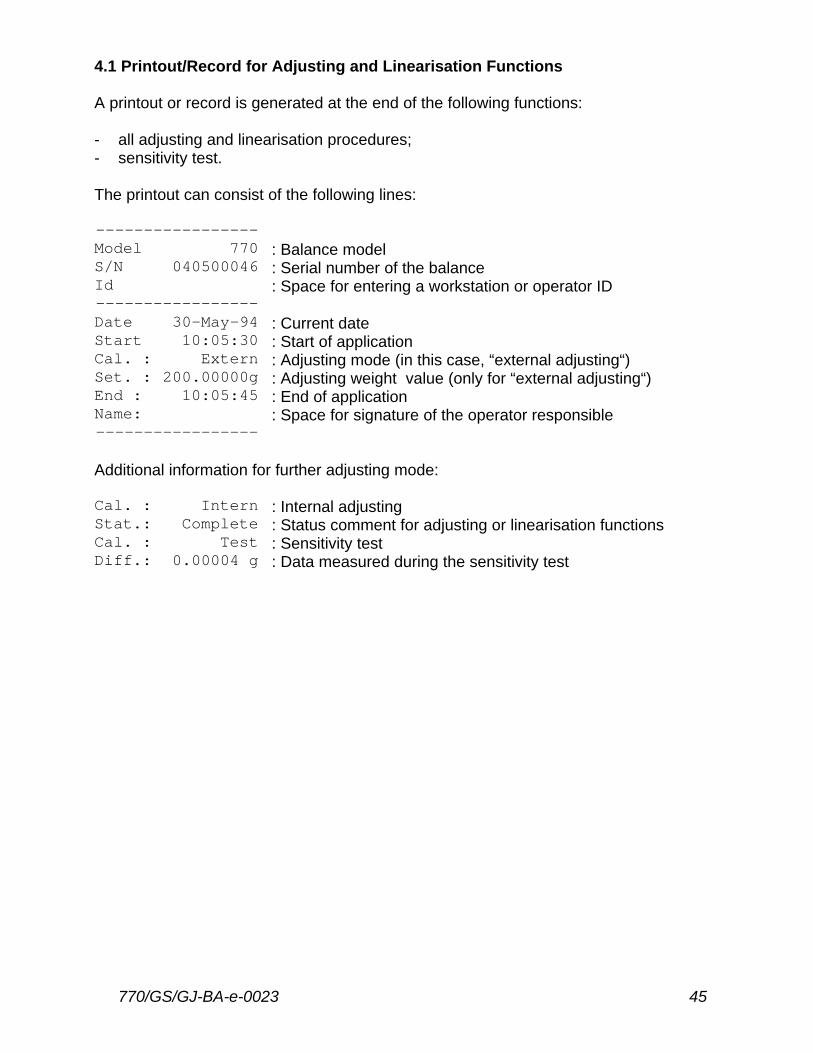
4.1 Printout/Record for Adjusting and Linearisation Functions A printout or record is generated at the end of the following functions: - all adjusting and linearisation procedures; - sensitivity test. The printout can consist of the following lines: ----------------- Model 770 : Balance model S/N 040500046 : Serial number of the balance Id : Space for entering a workstation or operator ID ----------------- Date 30-May-94 : Current date Start 10:05:30 : Start of application Cal. : Extern : Adjusting mode (in this case, “external adjusting“) Set. : 200.00000g : Adjusting weight value (only for “external adjusting“) End : 10:05:45 : End of application Name: : Space for signature of the operator responsible ----------------- Additional information for further adjusting mode: Cal. : Intern : Internal adjusting Stat.: Complete : Status comment for adjusting or linearisation functions Cal. : Test : Sensitivity test Diff.: 0.00004 g : Data measured during the sensitivity test
46 770/GS/GJ-BA-e-0023
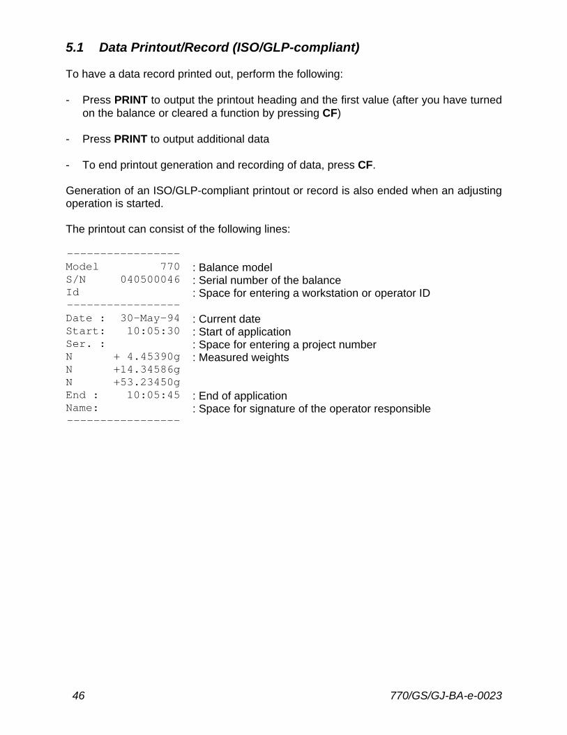
5.1 Data Printout/Record (ISO/GLP-compliant) To have a data record printed out, perform the following: - Press PRINT to output the printout heading and the first value (after you have turned
on the balance or cleared a function by pressing CF) - Press PRINT to output additional data - To end printout generation and recording of data, press CF. Generation of an ISO/GLP-compliant printout or record is also ended when an adjusting operation is started. The printout can consist of the following lines: ----------------- Model 770 : Balance model S/N 040500046 : Serial number of the balance Id : Space for entering a workstation or operator ID ----------------- Date : 30-May-94 : Current date Start: 10:05:30 : Start of application Ser. : : Space for entering a project number N + 4.45390g : Measured weights N +14.34586g N +53.23450g End : 10:05:45 : End of application Name: : Space for signature of the operator responsible -----------------
770/GS/GJ-BA-e-0023 47
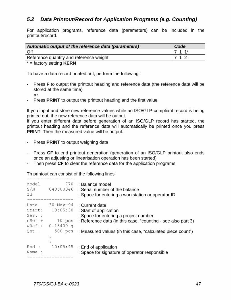
5.2 Data Printout/Record for Application Programs (e.g. Counting) For application programs, reference data (parameters) can be included in the printout/record. Automatic output of the reference data (parameters) Code Off 7 1 1* Reference quantity and reference weight 7 1 2 * = factory setting KERN To have a data record printed out, perform the following: - Press F to output the printout heading and reference data (the reference data will be
stored at the same time) or
- Press PRINT to output the printout heading and the first value. If you input and store new reference values while an ISO/GLP-compliant record is being printed out, the new reference data will be output. If you enter different data before generation of an ISO/GLP record has started, the printout heading and the reference data will automatically be printed once you press PRINT. Then the measured value will be output. - Press PRINT to output weighing data - Press CF to end printout generation (generation of an ISO/GLP printout also ends
once an adjusting or linearisation operation has been started) - Then press CF to clear the reference data for the application programs Th printout can consist of the following lines: ----------------- Model 770 : Balance model S/N 040500046 : Serial number of the balance Id : Space for entering a workstation or operator ID ----------------- Date 30-May-94 : Current date Start: 10:05:30 : Start of application Ser. : : Space for entering a project number nRef + 10 pcs : Reference data (in this case, “counting - see also part 3) wRef + 0.13400 g Qnt + 500 pcs : Measured values (in this case, “calculated piece count“)
: :
End : 10:05:45 : End of application Name : : Space for signature of operator responsible -----------------
48 770/GS/GJ-BA-e-0023
6 Interface Description 6.1 General Information This description has been written for users who wish to connect their KERN 770, GS and GJ balance which has a built-in RS 232 C interface port as a standard feature, to a computer or a different peripheral device. By using an on-line computer, you can change, activate and monitor the functions of the balance. In addition, an external universal switch for remote control of various functions can be connected to the data interface port on the balance. 6.2 Interfacing Devices with the Balance Please note that the interface port is electrically connected to the protective grounding conductor (protective earth = PE) of the balance housing. The cabling supplied as accessory components is shielded and electrically connected on both ends to the cases on the connectors. This electrical connection may result in interference caused by ground loops or by transient currents if you have grounded the housing or connected the protective grounding conductor for AC power. If necessary, connect an equipotential bonding conductor to the balance.
770/GS/GJ-BA-e-0023 49
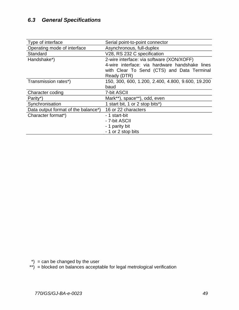
6.3 General Specifications Type of interface Serial point-to-point connector Operating mode of interface Asynchronous, full-duplex Standard V28, RS 232 C specification Handshake*) 2-wire interface: via software (XON/XOFF) 4-wire interface: via hardware handshake lines
with Clear To Send (CTS) and Data Terminal Ready (DTR)
Transmission rates*) 150, 300, 600, 1.200, 2.400, 4.800, 9.600, 19.200 baud
Character coding 7-bit ASCII Parity*) Mark**), space**), odd, even Synchronisation 1 start bit, 1 or 2 stop bits*) Data output format of the balance*) 16 or 22 characters Character format*) - 1 start-bit - 7-bit ASCII - 1 parity bit - 1 or 2 stop bits
*) = can be changed by the user **) = blocked on balances acceptable for legal metrological verification
50 770/GS/GJ-BA-e-0023
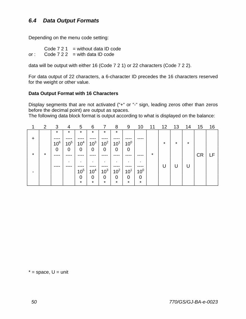
6.4 Data Output Formats Depending on the menu code setting: Code 7 2 1 = without data ID code or : Code 7 2 2 = with data ID code data will be output with either 16 (Code 7 2 1) or 22 characters (Code 7 2 2). For data output of 22 characters, a 6-character ID precedes the 16 characters reserved for the weight or other value. Data Output Format with 16 Characters Display segments that are not activated (“+“ or “-“ sign, leading zeros other than zeros before the decimal point) are output as spaces. The following data block format is output according to what is displayed on the balance:
1 2 3 4 5 6 7 8 9 10 11 12 13 14 15 16 * * * * * *
+ ---- ---- ---- ---- ---- ---- ---- ---- 106 105 104 103 102 101 100 * * * 0 0 0 0 0 0 0 * * ---- ---- ---- ---- ---- ---- ---- ---- * CR LF . . . . . . . ---- ---- ---- ---- ---- ---- ---- ---- U U U - 105 104 103 102 101 100 0 0 0 0 0 0 * * * * * *
* = space, U = unit

770/GS/GJ-BA-e-0023 51
When data are output without decimals, the decimal point is suppressed (except when a certain display mode is selected).
1 2 3 4 5 6 7 8 9 10 11 12 13 14 15 16 + * * * * * * ---- ---- ---- ---- ---- ---- ---- * * * * * * 106 105 104 103 102 101 100 * CR LF ---- ---- ---- ---- ---- ---- ---- U U U - 0 0 0 0 0 0
Data output example: + 12.5557 g
1 2 3 4 5 6 7 8 9 10 11 12 13 14 15 16 + * * 1 2 . 5 5 5 7 * g * * CR LF
Characters: 1st Plus or minus sign or space 2nd Space 3rd - 10th Weight with a decimal point; leading zeros = space 11th Space 12th - 14th Unit symbol or space 15th Carriage Return (CR) 16th Line Feed (LF) If the weighing system has not been stabilised, no unit symbol will be output. Unit symbols: * * * No stability parameter G N * Grains o * * Grams (o) d w t Pennyweights g * * Grams m g * Milligrams k g * Kilograms / l b Parts per Pound c t * Carats t l c Chinese taels l b * Pounds m o m Mommes o z * Ounces K * * Austrian carats o z t Troy Ounces t o l Tola t l h Hong Kong taels b a t Baht t l s Singapore taels M S * Mesghal t l t Taiwanese taels
* = space, U = unit
52 770/GS/GJ-BA-e-0023
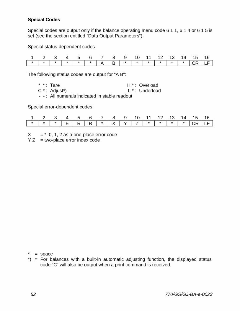
Special Codes Special codes are output only if the balance operating menu code 6 1 1, 6 1 4 or 6 1 5 is set (see the section entitled “Data Output Parameters“). Special status-dependent codes
1 2 3 4 5 6 7 8 9 10 11 12 13 14 15 16 * * * * * * A B * * * * * * CR LF
The following status codes are output for “A B“:
* * : Tare H * : Overload C * : Adjust*) L * : Underload - - : All numerals indicated in stable readout
Special error-dependent codes:
1 2 3 4 5 6 7 8 9 10 11 12 13 14 15 16 * * * E R R * X Y Z * * * * CR LF
X = *, 0, 1, 2 as a one-place error code Y Z = two-place error index code * = space *) = For balances with a built-in automatic adjusting function, the displayed status
code “C“ will also be output when a print command is received.

770/GS/GJ-BA-e-0023 53
Data Output with ID Code When data with an ID code is output, the ID code consisting of 6 characters precedes the data with the 16-character format. During data output, all characters are shifted to the right by 6 places. 1st character 7th 22ndC C C C C C V * x x x x x x x x * U U U CR LF * * * * * * * . . . . . . * * * V = Plus or minus sign * = Space x = Digit U = Unit . = Decimal point C = Letter for an ID comment CR = Carriage Return LF = Line Feed When special data codes are output, the letters “Stat“ for status code are assigned to the 1st through the 4th characters of the data string. Status-dependent string: 1st character 7th 13th 14th 22ndS t a t * * * * * * * * A B * * * * * * CR LF A, B = status codes Error-dependent string: 1st character 7th 10th - 12th 14th - 16th 22ndS t a t * * * * * E R R * X Y Z * * * * CR LF
54 770/GS/GJ-BA-e-0023
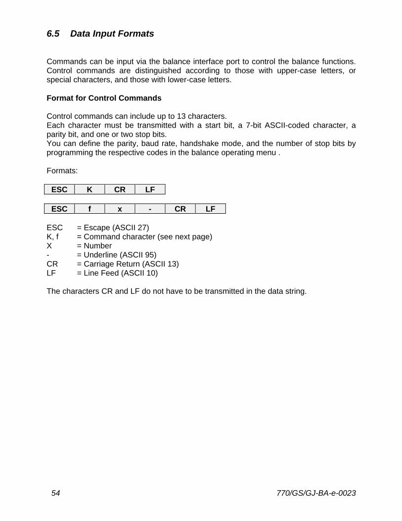
6.5 Data Input Formats Commands can be input via the balance interface port to control the balance functions. Control commands are distinguished according to those with upper-case letters, or special characters, and those with lower-case letters. Format for Control Commands Control commands can include up to 13 characters. Each character must be transmitted with a start bit, a 7-bit ASCII-coded character, a parity bit, and one or two stop bits. You can define the parity, baud rate, handshake mode, and the number of stop bits by programming the respective codes in the balance operating menu . Formats:
ESC K CR LF
ESC f x - CR LF ESC = Escape (ASCII 27) K, f = Command character (see next page) X = Number - = Underline (ASCII 95) CR = Carriage Return (ASCII 13) LF = Line Feed (ASCII 10) The characters CR and LF do not have to be transmitted in the data string.
770/GS/GJ-BA-e-0023 55
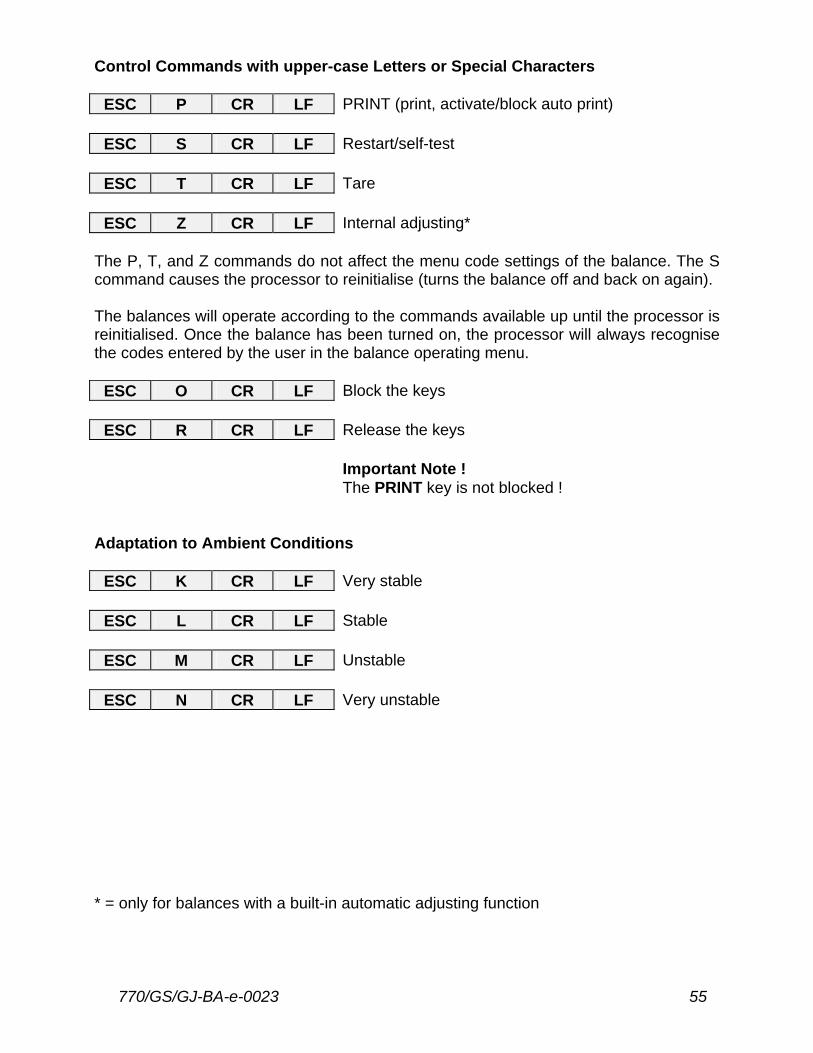
Control Commands with upper-case Letters or Special Characters
ESC P CR LF PRINT (print, activate/block auto print)
ESC S CR LF Restart/self-test
ESC T CR LF Tare
ESC Z CR LF Internal adjusting* The P, T, and Z commands do not affect the menu code settings of the balance. The S command causes the processor to reinitialise (turns the balance off and back on again). The balances will operate according to the commands available up until the processor is reinitialised. Once the balance has been turned on, the processor will always recognise the codes entered by the user in the balance operating menu.
ESC O CR LF Block the keys
ESC R CR LF Release the keys Important Note !
The PRINT key is not blocked ! Adaptation to Ambient Conditions
ESC K CR LF Very stable
ESC L CR LF Stable
ESC M CR LF Unstable
ESC N CR LF Very unstable * = only for balances with a built-in automatic adjusting function
56 770/GS/GJ-BA-e-0023
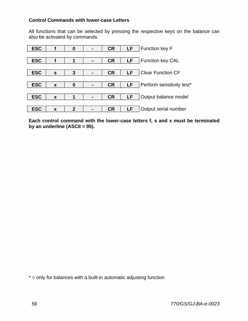
Control Commands with lower-case Letters All functions that can be selected by pressing the respective keys on the balance can also be activated by commands.
ESC f 0 - CR LF Function key F
ESC f 1 - CR LF Function key CAL
ESC s 3 - CR LF Clear Function CF
ESC x 0 - CR LF Perform sensitivity test*
ESC x 1 - CR LF Output balance model
ESC x 2 - CR LF Output serial number Each control command with the lower-case letters f, s and x must be terminated by an underline (ASCII = 95). * = only for balances with a built-in automatic adjusting function
770/GS/GJ-BA-e-0023 57
6.6 Synchronisation and Data Output Parameters Definition During data communication between the balance and an on-line device (computer), “telegram-style“ information consisting of ASCII characters is transmitted by the interface. For error-free data communication, the interface parameters, including the baud rate, parity and handshake mode as well as the character format, must be the same for both units. You can change these parameters in the balance operating menu so that they match those of the on-line device. If you do not plug a peripheral device into the interface port on the balance, this will not generate an error message. In this case, data will be output but not received. Handshake The balance interface has a 23-byte transmit buffer and a 40-byte receive buffer. You can access the balance operating menu to define various handshake parameters: Software handshake: - controlled by “XOFF“ and “XON“ Hardware handshake: - after “CTS“ send 2 characters
- after “CTS“ send 1 character What happens when you define a software handshake ? Receiving device: “XOFF“ will not be transmitted until the receive buffer has stored the 26th character. The enable command “XON“ is given after the buffer has transmitted all characters up to the 14th character. If the device addressed does not understand the control command, the receiving device continues to operate additionally with a hardware handshake after it has received another 6 characters.
58 770/GS/GJ-BA-e-0023
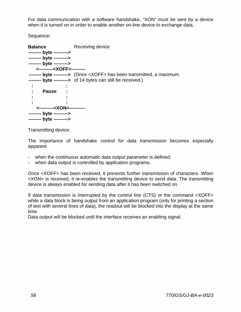
For data communication with a software handshake, “XON“ must be sent by a device when it is turned on in order to enable another on-line device to exchange data. Sequence: Balance Receiving device -------- byte ---------> -------- byte ---------> -------- byte --------->
<---------<XOFF>--------- -------- byte ---------> (Once <XOFF> has been transmitted, a maximum -------- byte ---------> of 14 bytes can still be received.)
: : : Pause : : : : :
<---------<XON>---------- -------- byte ---------> -------- byte ---------> Transmitting device: The importance of handshake control for data transmission becomes especially apparent - when the continuous automatic data output parameter is defined; - when data output is controlled by application programs. Once <XOFF> has been received, it prevents further transmission of characters. When <XON> is received, it re-enables the transmitting device to send data. The transmitting device is always enabled for sending data after it has been switched on. If data transmission is interrupted by the control line (CTS) or the command <XOFF> while a data block is being output from an application program (only for printing a section of text with several lines of data), the readout will be blocked into the display at the same time. Data output will be blocked until the interface receives an enabling signal.
770/GS/GJ-BA-e-0023 59
Activating a Data Output Process You can define the data output parameter so that output is activated either automatically or when a print command is received. You have two options for the automatic mode: data output can be either synchronous with the balance display or activated at defined intervals. Data Output by Print Command The print command can be transmitted by a software command or by pressing a key. In addition to an interface cable for a different device, you can connect an external universal switch for remote control to the balance interface port (print function: see part 2). For the switch, use pins 8 and 15 of this port and a cable up to 1.5 m or 5 ft. long (RS-232C). If data output is requested by a software command (see the section on “Data Input Formats“), you can install a 15 m (50ft.) cable for RS 232 C. Automatic Data Output In the “auto print“ operating mode, the data are output to the interface port without requiring a print command. You can choose to have data output automatically at defined print intervals or without the stability parameter. If you select the auto print setting, data will be transmitted immediately the moment you turn on the balance. Higher Data Output Rates If you require an output rate higher than 10Hz, ask KERN directly for this information.
60 770/GS/GJ-BA-e-0023
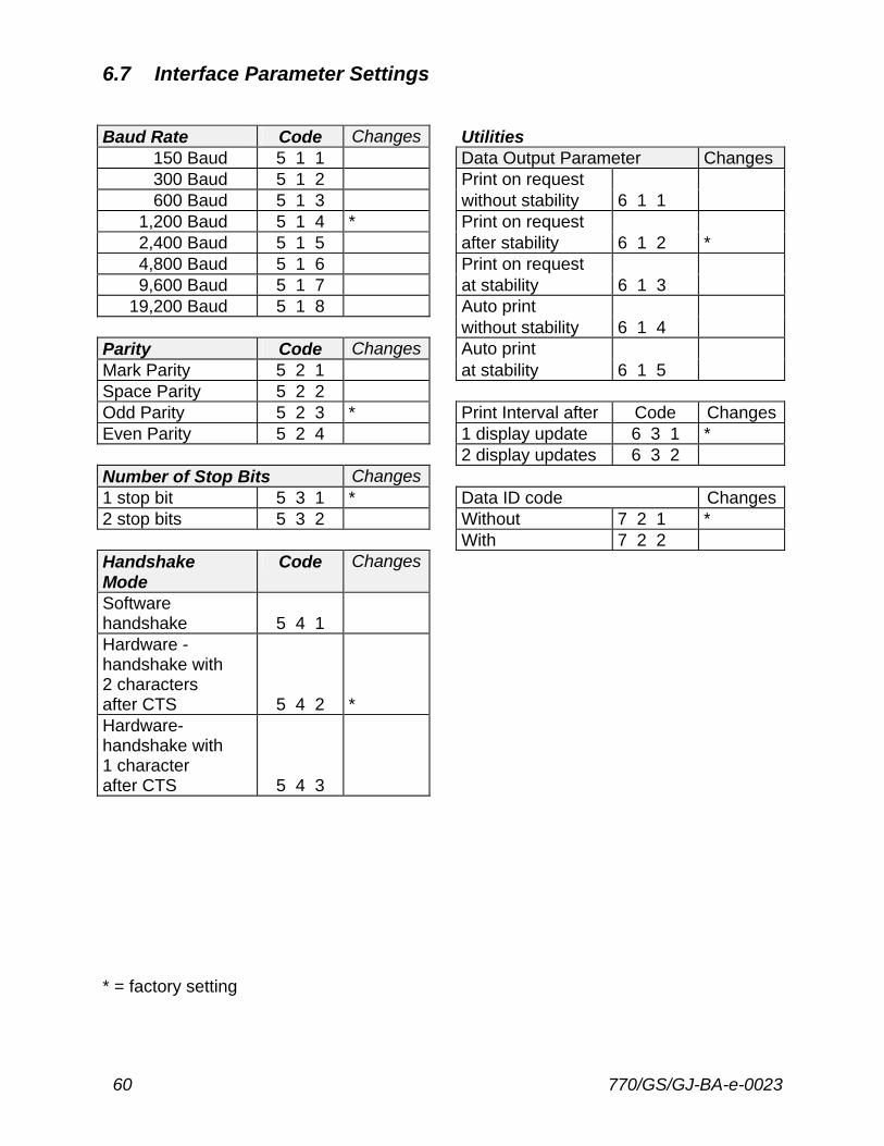
6.7 Interface Parameter Settings Baud Rate Code Changes Utilities
150 Baud 5 1 1 Data Output Parameter Changes 300 Baud 5 1 2 Print on request 600 Baud 5 1 3 without stability 6 1 1
1,200 Baud 5 1 4 * Print on request 2,400 Baud 5 1 5 after stability 6 1 2 * 4,800 Baud 5 1 6 Print on request 9,600 Baud 5 1 7 at stability 6 1 3
19,200 Baud 5 1 8 Auto print without stability 6 1 4 Parity Code Changes Auto print Mark Parity 5 2 1 at stability 6 1 5 Space Parity 5 2 2 Odd Parity 5 2 3 * Print Interval after Code ChangesEven Parity 5 2 4 1 display update 6 3 1 * 2 display updates 6 3 2 Number of Stop Bits Changes 1 stop bit 5 3 1 * Data ID code Changes2 stop bits 5 3 2 Without 7 2 1 * With 7 2 2 Handshake Mode
Code Changes
Software handshake
5 4 1
Hardware -handshake with 2 characters after CTS
5 4 2
*
Hardware-handshake with 1 character after CTS
5 4 3
* = factory setting
770/GS/GJ-BA-e-0023 61
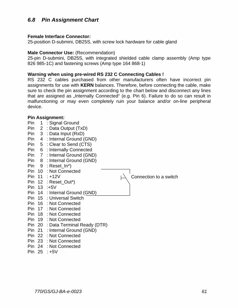
6.8 Pin Assignment Chart Female Interface Connector: 25-position D-submini, DB25S, with screw lock hardware for cable gland Male Connector Use: (Recommendation) 25-pin D-submini, DB25S, with integrated shielded cable clamp assembly (Amp type 826 985-1C) and fastening screws (Amp type 164 868-1) Warning when using pre-wired RS 232 C Connecting Cables ! RS 232 C cables purchased from other manufacturers often have incorrect pin assignments for use with KERN balances. Therefore, before connecting the cable, make sure to check the pin assignment according to the chart below and disconnect any lines that are assigned as „Internally Connected“ (e.g. Pin 6). Failure to do so can result in malfunctioning or may even completely ruin your balance and/or on-line peripheral device. Pin Assignment: Pin Pin Pin Pin Pin Pin Pin Pin Pin Pin Pin Pin Pin Pin Pin Pin Pin Pin Pin Pin Pin Pin Pin Pin Pin
1 2 3 4 5 6 7 8 9
10 11 12 13 14 15 16 17 18 19 20 21 22 23 24 25
: Signal Ground : Data Output (TxD) : Data Input (RxD) : Internal Ground (GND) : Clear to Send (CTS) : Internally Connected : Internal Ground (GND) : Internal Ground (GND) : Reset_In*) : Not Connected : +12V : Reset_Out*) :+5V : Internal Ground (GND) : Universal Switch : Not Connected : Not Connected : Not Connected : Not Connected : Data Terminal Ready (DTR) : Internal Ground (GND) : Not Connected : Not Connected : Not Connected : +5V
Connection to a switch
62 770/GS/GJ-BA-e-0023
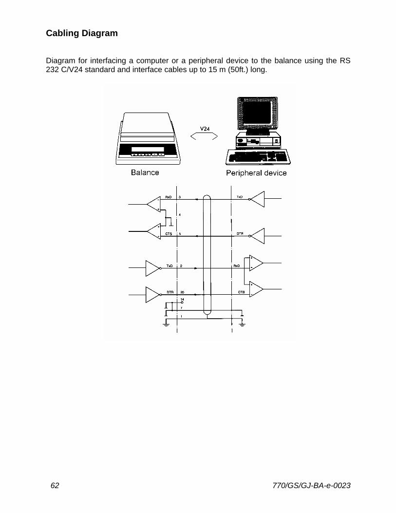
Cabling Diagram Diagram for interfacing a computer or a peripheral device to the balance using the RS 232 C/V24 standard and interface cables up to 15 m (50ft.) long.
770/GS/GJ-BA-e-0023 63
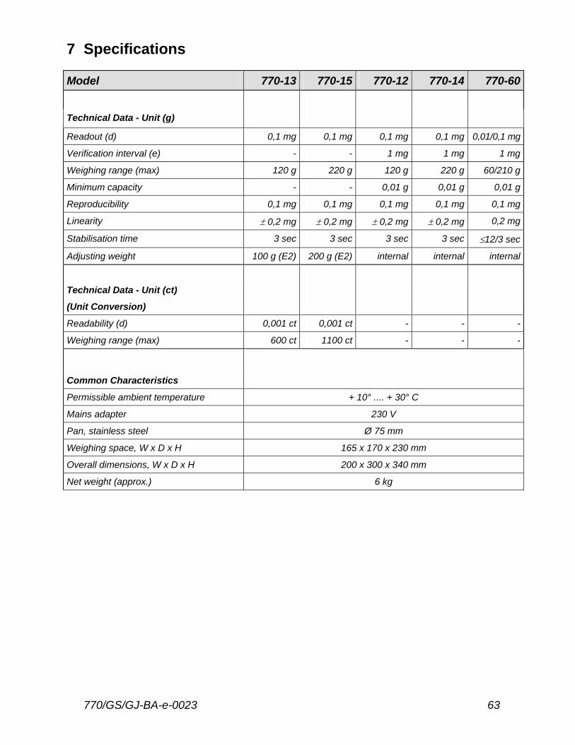
7 Specifications Model 770-13 770-15 770-12 770-14 770-60 Technical Data - Unit (g) Readout (d) 0,1 mg 0,1 mg 0,1 mg 0,1 mg 0,01/0,1 mg
Verification interval (e) - - 1 mg 1 mg 1 mg
Weighing range (max) 120 g 220 g 120 g 220 g 60/210 g
Minimum capacity - - 0,01 g 0,01 g 0,01 g
Reproducibility 0,1 mg 0,1 mg 0,1 mg 0,1 mg 0,1 mg
Linearity ± 0,2 mg ± 0,2 mg ± 0,2 mg ± 0,2 mg 0,2 mg
Stabilisation time 3 sec 3 sec 3 sec 3 sec ≤12/3 sec
Adjusting weight 100 g (E2) 200 g (E2) internal internal internal
Technical Data - Unit (ct)
(Unit Conversion)
Readability (d) 0,001 ct 0,001 ct - - -
Weighing range (max) 600 ct 1100 ct - - -
Common Characteristics
Permissible ambient temperature + 10° .... + 30° C
Mains adapter 230 V
Pan, stainless steel Ø 75 mm
Weighing space, W x D x H 165 x 170 x 230 mm
Overall dimensions, W x D x H 200 x 300 x 340 mm
Net weight (approx.) 6 kg

64 770/GS/GJ-BA-e-0023
Model GS 410-3 GS 620-6 GS 4100-2 GS 6200-1 Technical Data - Unit (g) Readout (d) 0,001 g 0,01 g 0,01 g 0,1 g
Verification interval (e) - - - -
Weighing range (Max) 410 g 620 g 4100 g 6200 g
Minimum capacity (Min) - - - -
Reproducibility 0,001 g 0,01 g 0,01 g 0,1 g
Linearity ± 0,002 g ± 0,01 g ± 0,02 g ± 0,1 g
Stabilisation time 2 sec. 2 sec. 2 sec. 2 sec.
Adjusting weight 200 g (F1) 500 g (F1) 2000 g (F1) 5000 g (F2)
Common Characteristics
Permissible ambient temperature + 10° .... + 30° C
Mains adapter 230 V
Pan, stainless steel (mm) Ø 80 mm Ø 115 mm 182 x 182 mm
Overall dimensions, W x D x H mm 200 x 300 x 340 mm
204 x 297 x 80,1 mm
204 x 297 x 80,5 mm
Net weight (approx.) 3,4 kg 1,9 kg 3,5 kg 3,0 kg
770/GS/GJ-BA-e-0023 65
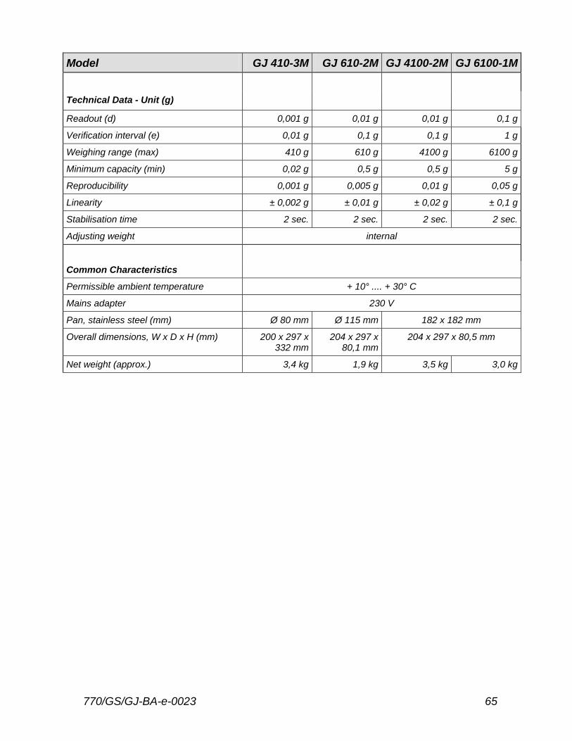
Model GJ 410-3M GJ 610-2M GJ 4100-2M GJ 6100-1M Technical Data - Unit (g) Readout (d) 0,001 g 0,01 g 0,01 g 0,1 g
Verification interval (e) 0,01 g 0,1 g 0,1 g 1 g
Weighing range (max) 410 g 610 g 4100 g 6100 g
Minimum capacity (min) 0,02 g 0,5 g 0,5 g 5 g
Reproducibility 0,001 g 0,005 g 0,01 g 0,05 g
Linearity ± 0,002 g ± 0,01 g ± 0,02 g ± 0,1 g
Stabilisation time 2 sec. 2 sec. 2 sec. 2 sec.
Adjusting weight internal
Common Characteristics
Permissible ambient temperature + 10° .... + 30° C
Mains adapter 230 V
Pan, stainless steel (mm) Ø 80 mm Ø 115 mm 182 x 182 mm
Overall dimensions, W x D x H (mm) 200 x 297 x 332 mm
204 x 297 x 80,1 mm
204 x 297 x 80,5 mm
Net weight (approx.) 3,4 kg 1,9 kg 3,5 kg 3,0 kg
66 770/GS/GJ-BA-e-0023
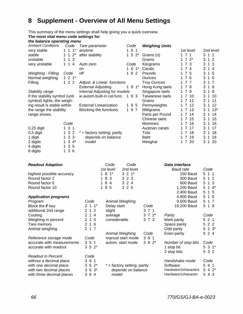
8 Supplement - Overview of All Menu Settings This summary of the menu settings shall help giving you a quick overview. The most vital menu code settings for the balance operating menu Ambient Conditions Code Tare parameter Code Weighing Units very stable 1 1 1* anytime 1 5 1 1st level 2nd level stable 1 1 2* after stability 1 5 2* Grams (o) 1 7 1 3 1 1 unstable 1 1 3 Grams 1 7 2* 3 1 2 very unstable 1 1 4 Auto zero Code Kilograms 1 7 3 3 1 3 on 1 6 1* Carats 1 7 4 3 1 4 Weighing - Filling Code off 1 6 2 Pounds 1 7 5 3 1 5 Normal weighing 1 2 1* Ounces 1 7 6 3 1 6 Filling 1 2 2 Adjust. & Linear. functions Troy Ounces 1 7 7 3 1 7 External Adjusting 1 9 1* Hong Kong taels 1 7 8 3 1 8 Stability range Internal Adjusting for models Singapore taels 1 7 9 3 1 9 If the stability symbol (unit w.autom.built-in cal.func. 1 9 3 Taiwanese taels 1 7 10 3 1 10 symbol) lights, the weigh- Grains 1 7 11 3 1 11 ing result is stable within External Linearization 1 9 5 Pennyweights 1 7 12 3 1 12 the range the stability Blocking the functions 1 9 7 Milligrams 1 7 13 3 1 13* range shows. Parts per Pound 1 7 14 3 1 14 Chinese taels 1 7 15 3 1 15 Code Mommes 1 7 16 3 1 16 0,25 digit 1 3 1 Austrian carats 1 7 17 3 1 17 0,5 digit 1 3 2 * = factory setting; partly Tola 1 7 18 3 1 18 1 digit 1 3 3 depends on balance Baht 1 7 19 3 1 19 2 digits 1 3 4* model Mesghal 1 7 20 3 1 20 4 digits 1 3 5 8 digits 1 3 6 Readout Adaption Code Code Data interface 1st level 2nd level Baud rate Code highest possible accuracy 1 8 1* 3 2 1* 150 Baud 5 1 1 Round factor 2 1 8 3 3 2 3 300 Baud 5 1 2 Round factor 5 1 8 4 3 2 4 600 Baud 5 1 3 Round factor 10 1 8 5 3 2 5 1,200 Baud 5 1 4* 2,400 Baud 5 1 5 Application programs 4,800 Baud 5 1 6 Program Code Animal Weighing 9,600 Baud 5 1 7 Block the F key 2 1 1* Delay start Code 19,200 Baud 5 1 8 additional 2nd range 2 1 2 slight 3 7 1 Couting 2 1 4 average 3 7 2* Parity Code Weighing in percent 2 1 5 considerable 3 7 3 Mark parity 5 2 1 Tare memory 2 1 6 Space parity 5 2 2 Animal weighing 2 1 7 Odd parity 5 2 3* Animal Weighing Code Even parity 5 2 4 Reference storage mode Code manual start mode 3 8 1 accurate with measurements 3 5 1 autom. start mode 3 8 2* Number of stop bits Code accurate with readout 3 5 2* 1 stop bit 5 3 1* 2 stop bits 5 3 2 Readout in Percent Code without a decimal place 3 6 1 Handshake mode Code with one decimal place 3 6 2* * = factory setting; partly Software 5 4 1 with two decimal places 3 6 3* depends on balance Hardware/2characters 5 4 2* with three decimal places 3 6 4 model Hardware/1character 5 4 3
770/GS/GJ-BA-e-0023 67
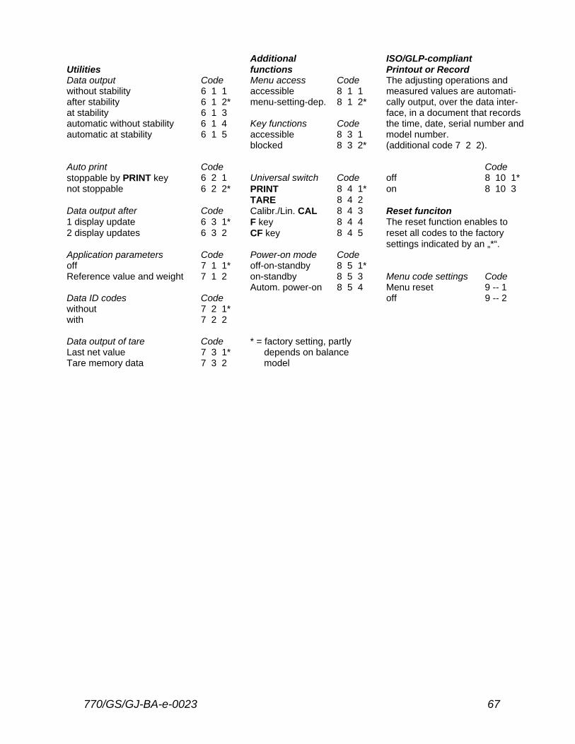
Additional ISO/GLP-compliant Utilities functions Printout or Record Data output Code Menu access Code The adjusting operations and without stability 6 1 1 accessible 8 1 1 measured values are automati- after stability 6 1 2* menu-setting-dep. 8 1 2* cally output, over the data inter- at stability 6 1 3 face, in a document that records automatic without stability 6 1 4 Key functions Code the time, date, serial number and automatic at stability 6 1 5 accessible 8 3 1 model number. blocked 8 3 2* (additional code 7 2 2). Auto print Code Code stoppable by PRINT key 6 2 1 Universal switch Code off 8 10 1* not stoppable 6 2 2* PRINT 8 4 1* on 8 10 3 TARE 8 4 2 Data output after Code Calibr./Lin. CAL 8 4 3 Reset funciton 1 display update 6 3 1* F key 8 4 4 The reset function enables to 2 display updates 6 3 2 CF key 8 4 5 reset all codes to the factory settings indicated by an „*“. Application parameters Code Power-on mode Code off 7 1 1* off-on-standby 8 5 1* Reference value and weight 7 1 2 on-standby 8 5 3 Menu code settings Code Autom. power-on 8 5 4 Menu reset 9 -- 1 Data ID codes Code off 9 -- 2 without 7 2 1* with 7 2 2 Data output of tare Code * = factory setting, partly Last net value 7 3 1* depends on balance Tare memory data 7 3 2 model