Embed Size (px)
Citation preview
1 of 73
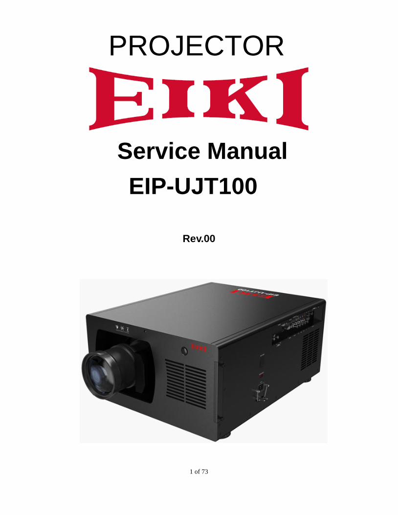
PROJECTOR
Service Manual
EIP-UJT100
Rev.00
2 of 73
DLP DIGITAL PROJECTOR rev.00
Revision Description Date
Rev.00 Preliminary 5/13/2015
3 of 73
CONTENTS
1,COMPLIANCE OF SAFE REPAIR .......................................................................... 4
1-1 Cautions during disassembling and assembling……………………….…………….4
1-2 Lamp………………………………………………..……………….………….…………… 4
1-3 Lens………………………………………...………..………………………….…………….4
2. SPECIFICATIONS .............................................................................................. 5
2-1 Optical Specifications…………….….……………………………………..…………….5
2-2 Block Diagram…………………………….….…………………………………………….6
2-3 Fan Location. ........................................................................................................... 7
3. TROUBLESHOOTING ......................................................................................... 9
3-1 Control Keys and LED Indicators………………………………………….………..…..9
3-2 RS-232 Settings…………………..……………………………………………………….10
4. KEY PART REPLACEMENT & WIRE DRESSING…...……………………….…………...…19
5. ADJUSTING……………..…………………………….…………..…….…..….…...…51
5-1 Folding Mirror Adjusting..………..………………………….…………………………..51
5-2 Focus Adjusting…..………………..………………………….…………………………..52
6. MAINTENANCE………………………..…………………………………………..…………..….57
6-1 Cleaning the projector………………………………….….…….……………………....57
6-1-1 Cleaning the cabinet.….………………….……….…………..….…….......57
6-1-2 Cleaning the Lens.……...……….……….…….……..……….….…….......57
6-1-3 Replace the filters.…………..………….….….…….…….…………….…..57
6-1-4 Cleaning the optical parts………………….….….…………….……..……58
6-2 Replacing Consumable Parts………………………….….…….……….…………..….59
6-3 Replacing the Lamp……….…………………………….….…….……….………….…..60
6-4 Replacing the Filter……….….………………………….….…….……………………....63
7. SPART PARTS LIST & SPARE PARTS PHOTO………..…………………………..……..…65
APPENDIX TIMING TABLE………………………………………………….…….….………...…71
4 of 73
1. COMPLIANCE OF SAFE REPAIR
Be sure to read this Service Manual before providing services.
In the projector, full consideration is taken to ensure the safety for fire, electric shock, injury, harmful radiation,
and substance. Therefore, observe the notice described in this Service Manual so that safety is kept when
providing services. Moreover, be sure to observe the notice described in the Instruction Manual.
Pay attention to the following during service inspection.
1-1 Cautions during disassembling and assembling
1. This equipment contains parts under high voltage. When making repairs, etc. Be sure to pull out the power
plug beforehand to insure safety.
2. Parts may be very hot immediately after use. Make sure the equipment has cooled off sufficiently before
carrying out repairs.
3. Make sure that parts and screws and wiring, etc. are returned to their original positions. Tube, tape and
other insulation materials have been used for safety reasons. The internal wiring has been designed to
avoid direct contact with hot parts or parts under high voltage when using clamps or other tools.
4. The parts used in this device have special safety features such as flame-resistance and anti-voltage
properties. When replacing parts, always use parts supplied from the factory.
5. After finishing operations make sure that all parts and wires have been returned to their original position and
that there has been no deterioration of the area around the location that was worked on.
6. Be sure to use an earth band (wrist band) during repair and inspection.
1-2 Lamp
During current conduction, the lamp is in the high-temperature state. In this case, pay careful attention
because a high voltage is used. When replacing a lamp, replace it after confirming that the lamp has cooled
sufficiently.
1-3 Lens
Do not look into the lens during projection. This damages your eyes.
5 of 73
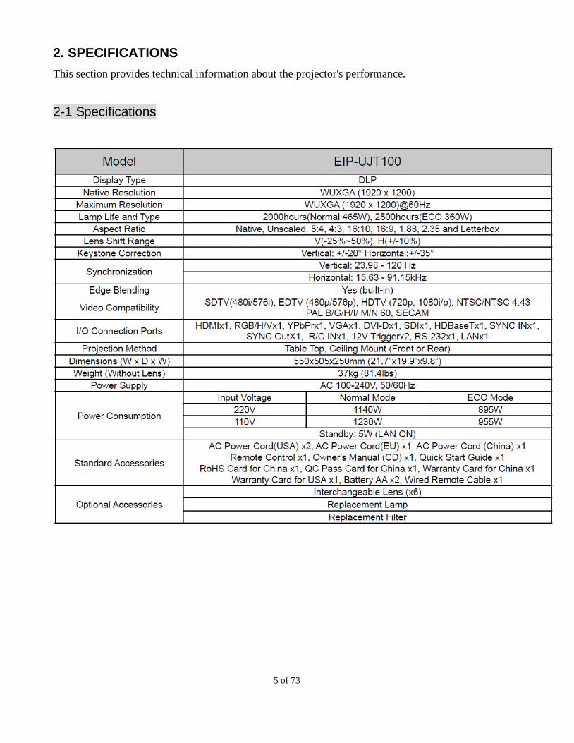
2. SPECIFICATIONS
This section provides technical information about the projector's performance.
2-1 Specifications
6 of 73
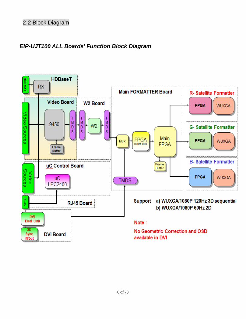
2-2 Block Diagram
EIP-UJT100 ALL Boards' Function Block Diagram
7 of 73
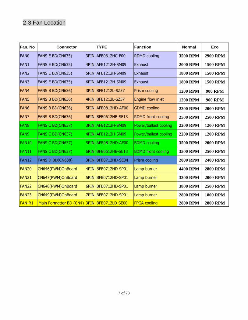
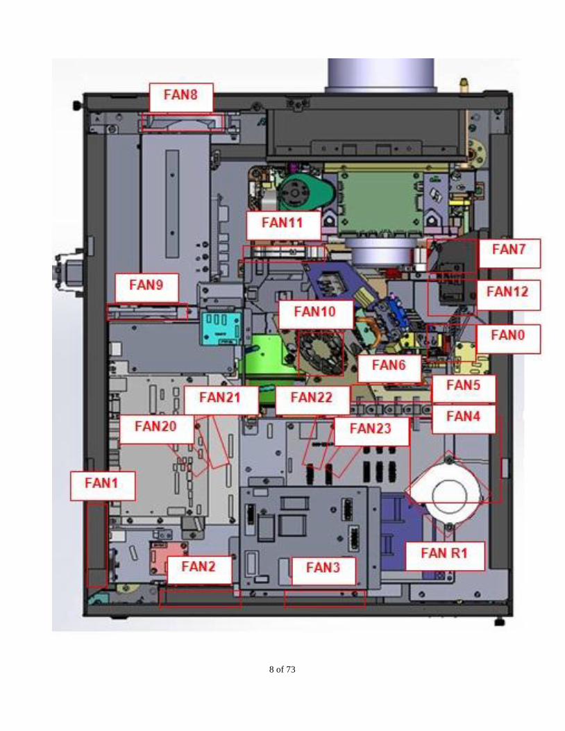
2-3 Fan Location
Fan. No Connector TYPE Function Normal Eco
FAN0 FANS E BD(CN635) 3PIN AFB0612HC-F00 RDMD cooling 3500 RPM 2900 RPM
FAN1 FANS E BD(CN635) 4PIN AFB1212H-SM09 Exhaust 2000 RPM 1500 RPM
FAN2 FANS E BD(CN635) 5PIN AFB1212H-SM09 Exhaust 1800 RPM 1500 RPM
FAN3 FANS E BD(CN635) 6PIN AFB1212H-SM09 Exhaust 1800 RPM 1500 RPM
FAN4 FANS B BD(CN636) 3PIN BFB1212L-SZ57 Prism cooling 1200 RPM 900 RPM
FAN5 FANS B BD(CN636) 4PIN BFB1212L-SZ57 Engine flow inlet 1200 RPM 900 RPM
FAN6 FANS B BD(CN636) 5PIN AFB0812HD-AF00 GDMD cooling 2300 RPM 2000 RPM
FAN7 FANS B BD(CN636) 6PIN BFB0612HB-SE13 RDMD front cooling 2500 RPM 2500 RPM
FAN8 FANS C BD(CN637) 3PIN AFB1212H-SM09 Power/ballast cooling 2200 RPM 1200 RPM
FAN9 FANS C BD(CN637) 4PIN AFB1212H-SM09 Power/ballast cooling 2200 RPM 1200 RPM
FAN10 FANS C BD(CN637) 5PIN AFB0812HD-AF00 BDMD cooling 3500 RPM 2000 RPM
FAN11 FANS C BD(CN637) 6PIN BFB0612HB-SE13 BDMD front cooling 3500 RPM 2500 RPM
FAN12 FANS D BD(CN638) 3PIN BFB0712HD-SE04 Prism cooling 2800 RPM 2400 RPM
FAN20 CN646(PWM)OnBoard 4PIN BFB0712HD-SP01 Lamp burner 4400 RPM 2800 RPM
FAN21 CN647(PWM)OnBoard 5PIN BFB0712HD-SP01 Lamp burner 3300 RPM 2000 RPM
FAN22 CN648(PWM)OnBoard 6PIN BFB0712HD-SP01 Lamp burner 3800 RPM 2500 RPM
FAN23 CN649(PWM)OnBoard 7PIN BFB0712HD-SP01 Lamp burner 2800 RPM 1800 RPM
FAN-R1 Main Formatter BD (CN4) 3PIN BFB0712LD-SE00 FPGA cooling 2800 RPM 2800 RPM
8 of 73
9 of 73
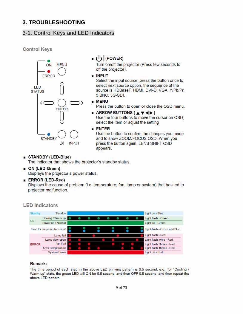
3. TROUBLESHOOTING
3-1. Control Keys and LED Indicators
10 of 73
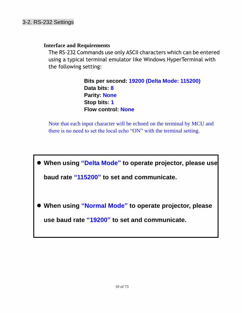
3-2. RS-232 Settings
Interface and Requirements
The RS-232 Commands use only ASCII characters which can be entered
using a typical terminal emulator like Windows HyperTerminal with
the following setting:
Bits per second: 19200 (Delta Mode: 115200)
Data bits: 8
Parity: None
Stop bits: 1
Flow control: None
Note that each input character will be echoed on the terminal by MCU and
there is no need to set the local echo “ON” with the terminal setting.
When using “Delta Mode” to operate projector, please use
baud rate “115200” to set and communicate.
When using “Normal Mode” to operate projector, please
use baud rate “19200” to set and communicate.
11 of 73
A. Use RS-232 comment to Retrieve Error Code
Step0. A. Connect the AC power of the projector and have the projector in standby mode.
Step1. A. Connect the RS-232 cable between the projector and the PC.
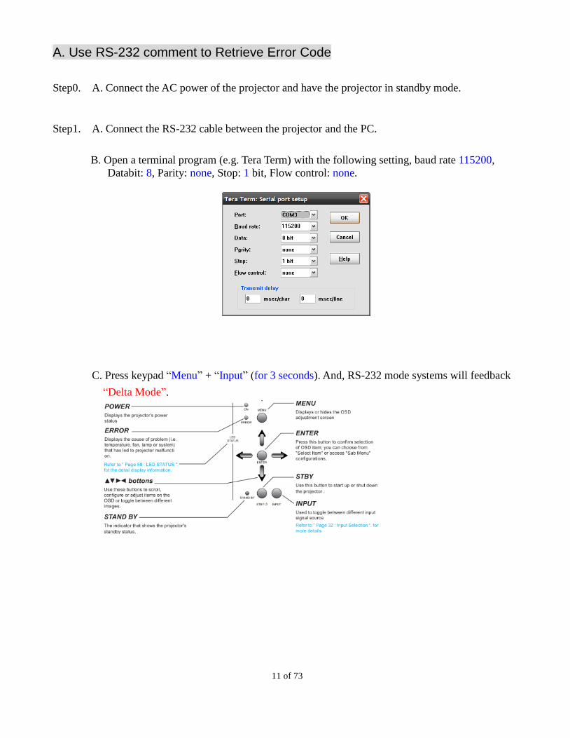
B. Open a terminal program (e.g. Tera Term) with the following setting, baud rate 115200,
Databit: 8, Parity: none, Stop: 1 bit, Flow control: none.
C. Press keypad “Menu” + “Input” (for 3 seconds). And, RS-232 mode systems will feedback
“Delta Mode”.
12 of 73
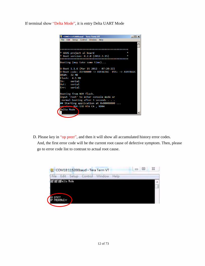
If terminal show “Delta Mode”, it is entry Delta UART Mode
D. Please key in “op prerr”, and then it will show all accumulated history error codes.
And, the first error code will be the current root cause of defective symptom. Then, please
go to error code list to contrast to actual root cause.
13 of 73
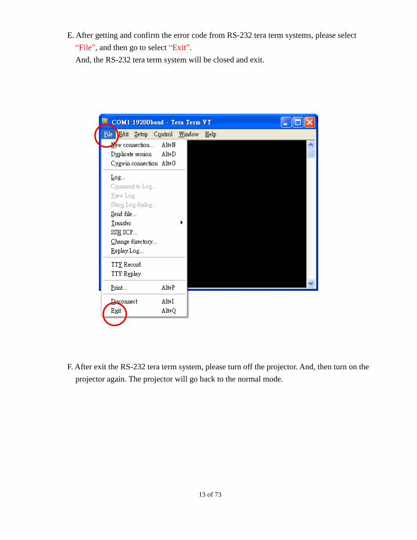
E. After getting and confirm the error code from RS-232 tera term systems, please select
“File”, and then go to select “Exit”.
And, the RS-232 tera term system will be closed and exit.
F. After exit the RS-232 tera term system, please turn off the projector. And, then turn on the
projector again. The projector will go back to the normal mode.
14 of 73
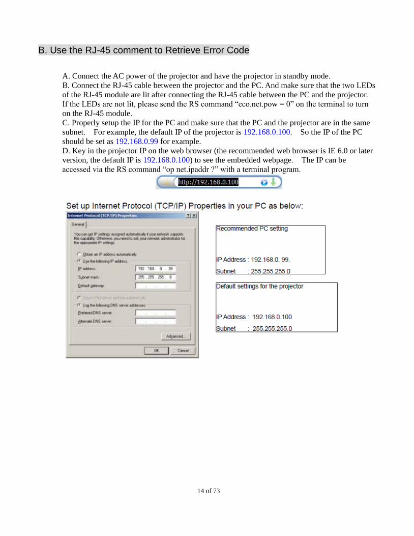
B. Use the RJ-45 comment to Retrieve Error Code
A. Connect the AC power of the projector and have the projector in standby mode.
B. Connect the RJ-45 cable between the projector and the PC. And make sure that the two LEDs
of the RJ-45 module are lit after connecting the RJ-45 cable between the PC and the projector.
If the LEDs are not lit, please send the RS command “eco.net.pow = 0” on the terminal to turn
on the RJ-45 module.
C. Properly setup the IP for the PC and make sure that the PC and the projector are in the same
subnet. For example, the default IP of the projector is 192.168.0.100. So the IP of the PC
should be set as 192.168.0.99 for example.
D. Key in the projector IP on the web browser (the recommended web browser is IE 6.0 or later
version, the default IP is 192.168.0.100) to see the embedded webpage. The IP can be
accessed via the RS command “op net.ipaddr ?” with a terminal program.
15 of 73
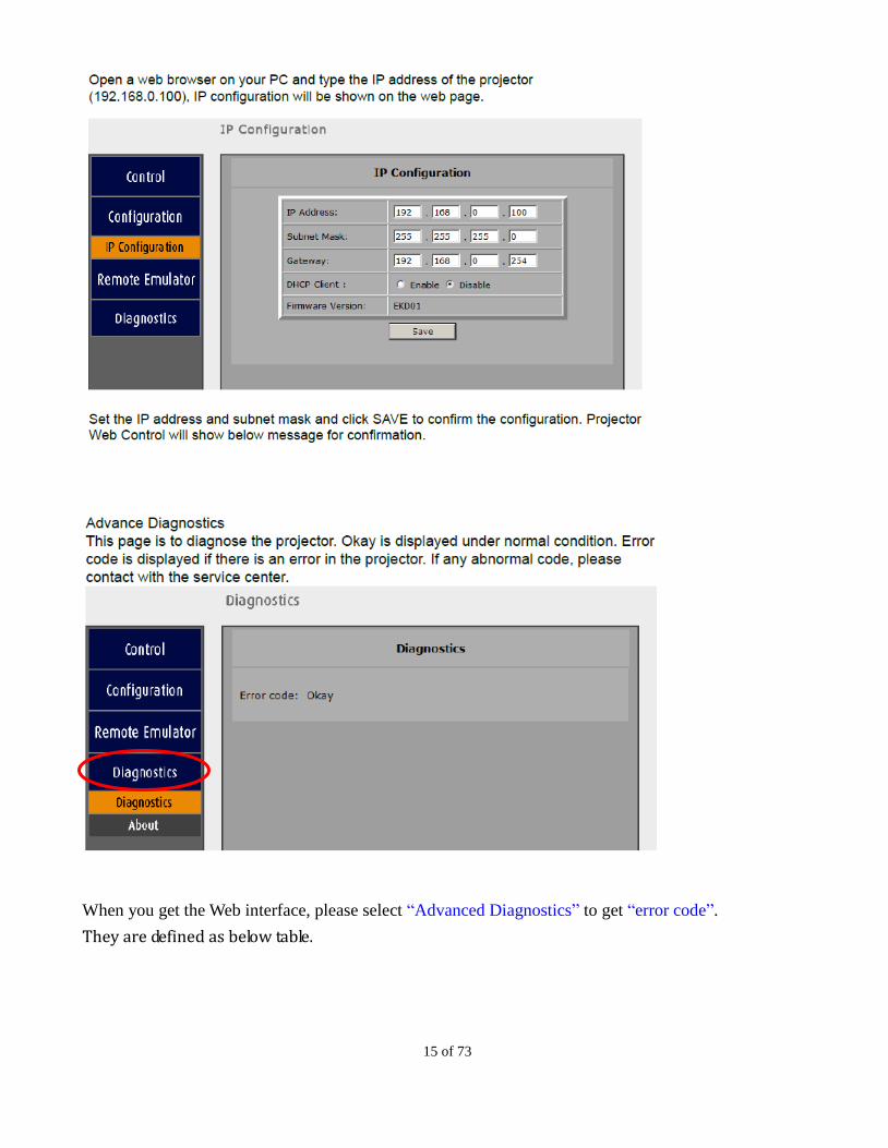
When you get the Web interface, please select “Advanced Diagnostics” to get “error code”.
They are defined as below table.
16 of 73
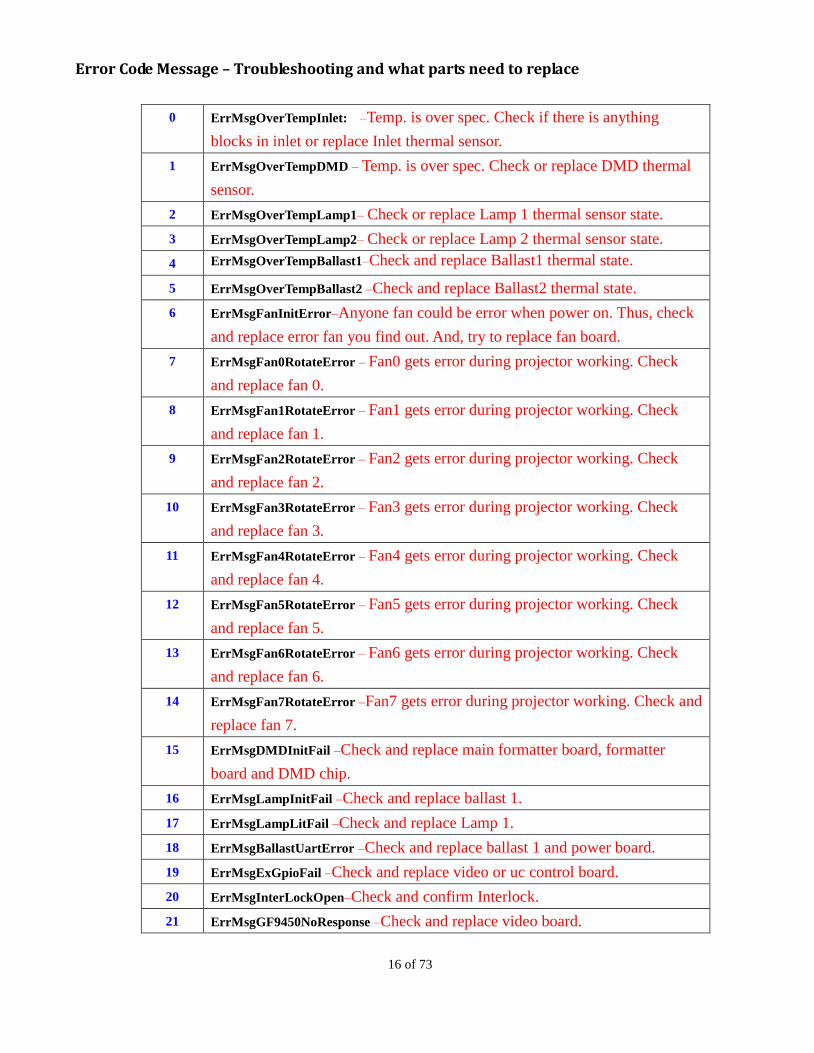
Error Code Message – Troubleshooting and what parts need to replace
0 ErrMsgOverTempInlet: –Temp. is over spec. Check if there is anything
blocks in inlet or replace Inlet thermal sensor.
1 ErrMsgOverTempDMD – Temp. is over spec. Check or replace DMD thermal
sensor.
2 ErrMsgOverTempLamp1– Check or replace Lamp 1 thermal sensor state.
3 ErrMsgOverTempLamp2– Check or replace Lamp 2 thermal sensor state.
4 ErrMsgOverTempBallast1–Check and replace Ballast1 thermal state.
5 ErrMsgOverTempBallast2 –Check and replace Ballast2 thermal state.
6 ErrMsgFanInitError–Anyone fan could be error when power on. Thus, check
and replace error fan you find out. And, try to replace fan board.
7 ErrMsgFan0RotateError – Fan0 gets error during projector working. Check
and replace fan 0.
8 ErrMsgFan1RotateError – Fan1 gets error during projector working. Check
and replace fan 1.
9 ErrMsgFan2RotateError – Fan2 gets error during projector working. Check
and replace fan 2.
10 ErrMsgFan3RotateError – Fan3 gets error during projector working. Check
and replace fan 3.
11 ErrMsgFan4RotateError – Fan4 gets error during projector working. Check
and replace fan 4.
12 ErrMsgFan5RotateError – Fan5 gets error during projector working. Check
and replace fan 5.
13 ErrMsgFan6RotateError – Fan6 gets error during projector working. Check
and replace fan 6.
14 ErrMsgFan7RotateError –Fan7 gets error during projector working. Check and
replace fan 7.
15 ErrMsgDMDInitFail –Check and replace main formatter board, formatter
board and DMD chip.
16 ErrMsgLampInitFail –Check and replace ballast 1.
17 ErrMsgLampLitFail –Check and replace Lamp 1.
18 ErrMsgBallastUartError –Check and replace ballast 1 and power board.
19 ErrMsgExGpioFail –Check and replace video or uc control board.
20 ErrMsgInterLockOpen–Check and confirm Interlock.
21 ErrMsgGF9450NoResponse –Check and replace video board.

17 of 73
22 ErrMsgSystemI2cFail –Check and replace all board.
23 ErrMsgSoftwareI2cFail –Check and replace all board.
24 ErrMsgEepromFail –Check and replace uc control board.
25 ErrMsgEdidFail–Check and replace video board.
26 ErrMsgEepVersionFail–Check and replace video board.
27 ErrMsgRstGennum –Check and replace video board.
28 ErrMsgFan8RotateError –Fan8 gets error during projector working. Check and
replace fan 8.
29 ErrMsgFan9RotateError –Fan9 gets error during projector working. Check and
replace fan 9. 30 ErrMsgFan10RotateError –Fan10 gets error during projector working. Check
and replace fan 10.
31 ErrMsgFan11RotateError –Fan11 gets error during projector working. Check
and replace fan 11.
32 ErrMsgLamp2LitFail ––Check and replace Lamp 2.
33 ErrMsgBallast2UartError ––Check and replace ballast 2 and power board.
34 ErrMsgGtInletTp ––Check or replace Inlet thermal sensor.
35 ErrMsgGtDmdTp –Check or replace DMD thermal sensor.
36 ErrMsgInletTempSensorFail––Reserved & None for this model.
37 ErrMsgDMDTempSensorFail –Reserved & None for this model.
38 ErrMsgGeoSystemFail – Check and replace the W2 board.
39 ErrMsgNormal ––Reserved & None for this model.
40 ErrMsgFan12RotateError ––Fan12 gets error during projector working. Check
and replace fan 12.
41 ErrMsgFan13RotateError –– Reserved & None for this model.
42 ErrMsgFan14RotateError –– Reserved & None for this model.
43 ErrMsgFan15RotateError –– Reserved & None for this model.
44 ErrMsgFan16RotateError –– Reserved & None for this model.
45 ErrMsgFan17RotateError –– Reserved & None for this model.
46 ErrMsgFan18RotateError –– Reserved & None for this model.
47 ErrMsgFan19RotateError –– Reserved & None for this model.
48 ErrMsgFan20RotateError ––Fan20 gets error during projector working. Check
and replace fan 20.
49 ErrMsgFan21RotateError ––Fan21 gets error during projector working. Check
and replace fan 21.
50 ErrMsgFan22RotateError –Fan22 gets error during projector working. Check
and replace fan 22.
18 of 73
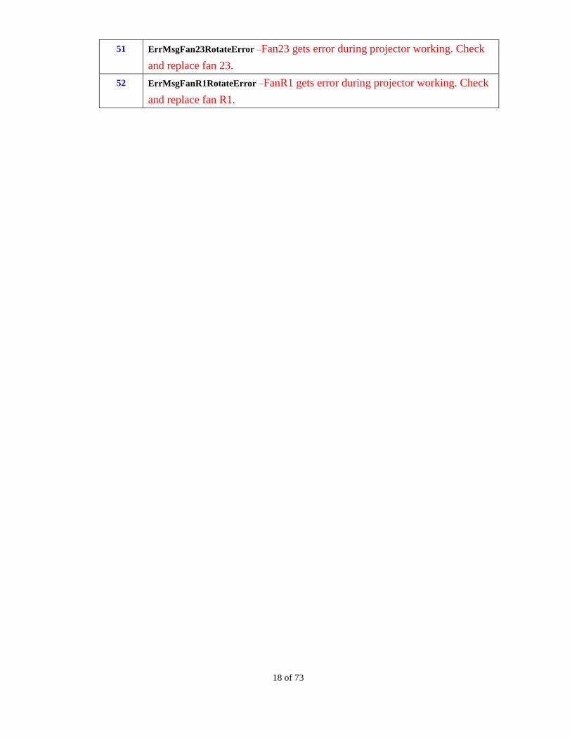
51 ErrMsgFan23RotateError –Fan23 gets error during projector working. Check
and replace fan 23.
52 ErrMsgFanR1RotateError –FanR1 gets error during projector working. Check
and replace fan R1.
19 of 73
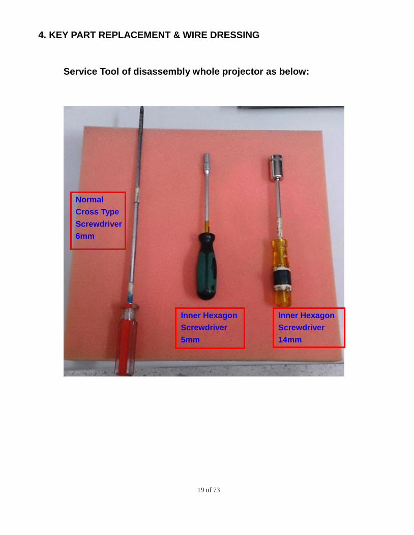
4. KEY PART REPLACEMENT & WIRE DRESSING
Service Tool of disassembly whole projector as below:
Inner Hexagon
Screwdriver
5mm
Inner Hexagon
Screwdriver
14mm
Normal
Cross Type
Screwdriver
6mm

20 of 73
4-1 Top Cover
Put the projector on the table. Take out the sponge from the
projector. And, loosen 1 screw on the
front cover. (Torque: 70~80 Nm)
Loosen 3 screws on the back of top cover.
(Torque: 70~80 Nm)
Open the top cover.
21 of 73
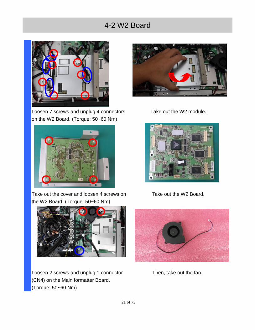
4-2 W2 Board
Loosen 7 screws and unplug 4 connectors
on the W2 Board. (Torque: 50~60 Nm)
Take out the W2 module.
Take out the cover and loosen 4 screws on
the W2 Board. (Torque: 50~60 Nm)
Take out the W2 Board.
Loosen 2 screws and unplug 1 connector
(CN4) on the Main formatter Board.
(Torque: 50~60 Nm)
Then, take out the fan.
22 of 73
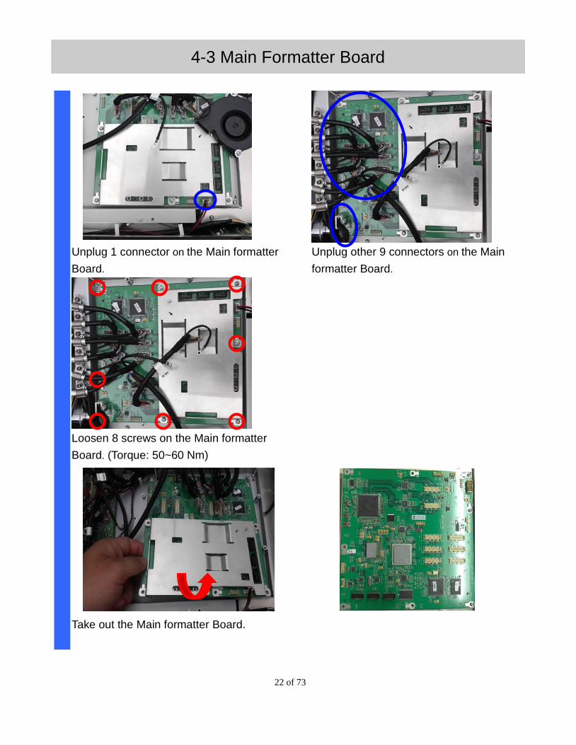
4-3 Main Formatter Board
Unplug 1 connector on the Main formatter
Board.
Unplug other 9 connectors on the Main
formatter Board.
Loosen 8 screws on the Main formatter
Board. (Torque: 50~60 Nm)
Take out the Main formatter Board.
23 of 73
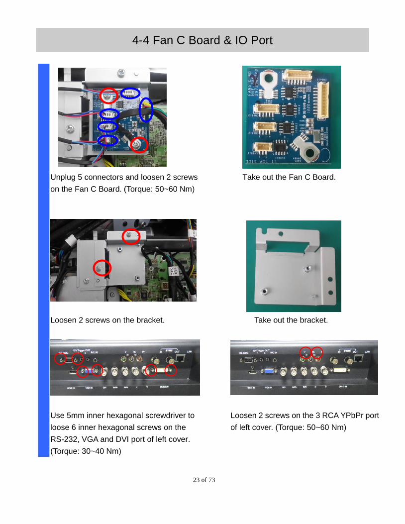
4-4 Fan C Board & IO Port
Unplug 5 connectors and loosen 2 screws
on the Fan C Board. (Torque: 50~60 Nm)
Take out the Fan C Board.
Loosen 2 screws on the bracket. Take out the bracket.
Use 5mm inner hexagonal screwdriver to
loose 6 inner hexagonal screws on the
RS-232, VGA and DVI port of left cover.
(Torque: 30~40 Nm)
Loosen 2 screws on the 3 RCA YPbPr port
of left cover. (Torque: 50~60 Nm)
24 of 73
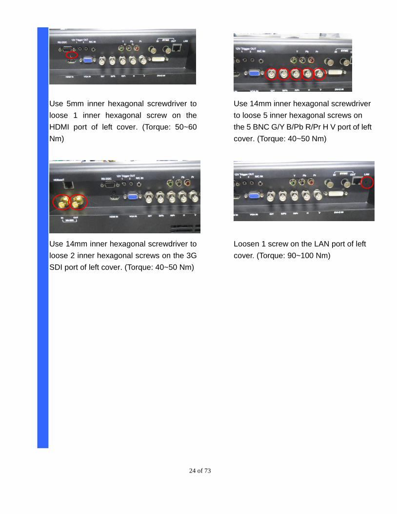
Use 5mm inner hexagonal screwdriver to
loose 1 inner hexagonal screw on the
HDMI port of left cover. (Torque: 50~60
Nm)
Use 14mm inner hexagonal screwdriver to
loose 2 inner hexagonal screws on the 3G
SDI port of left cover. (Torque: 40~50 Nm)
Use 14mm inner hexagonal screwdriver
to loose 5 inner hexagonal screws on
the 5 BNC G/Y B/Pb R/Pr H V port of left
cover. (Torque: 40~50 Nm)
Loosen 1 screw on the LAN port of left
cover. (Torque: 90~100 Nm)
25 of 73
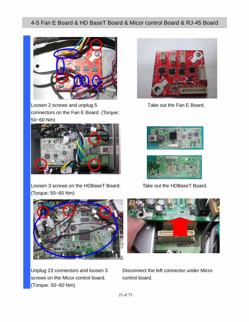
4-5 Fan E Board & HD BaseT Board & Micor control Board & RJ-45 Board
Loosen 2 screws and unplug 5
connectors on the Fan E Board. (Torque:
50~60 Nm)
Take out the Fan E Board.
Loosen 3 screws on the HDBaseT Board.
(Torque: 50~60 Nm)
Take out the HDBaseT Board.
Unplug 23 connectors and loosen 3
screws on the Micor control board.
(Torque: 50~60 Nm)
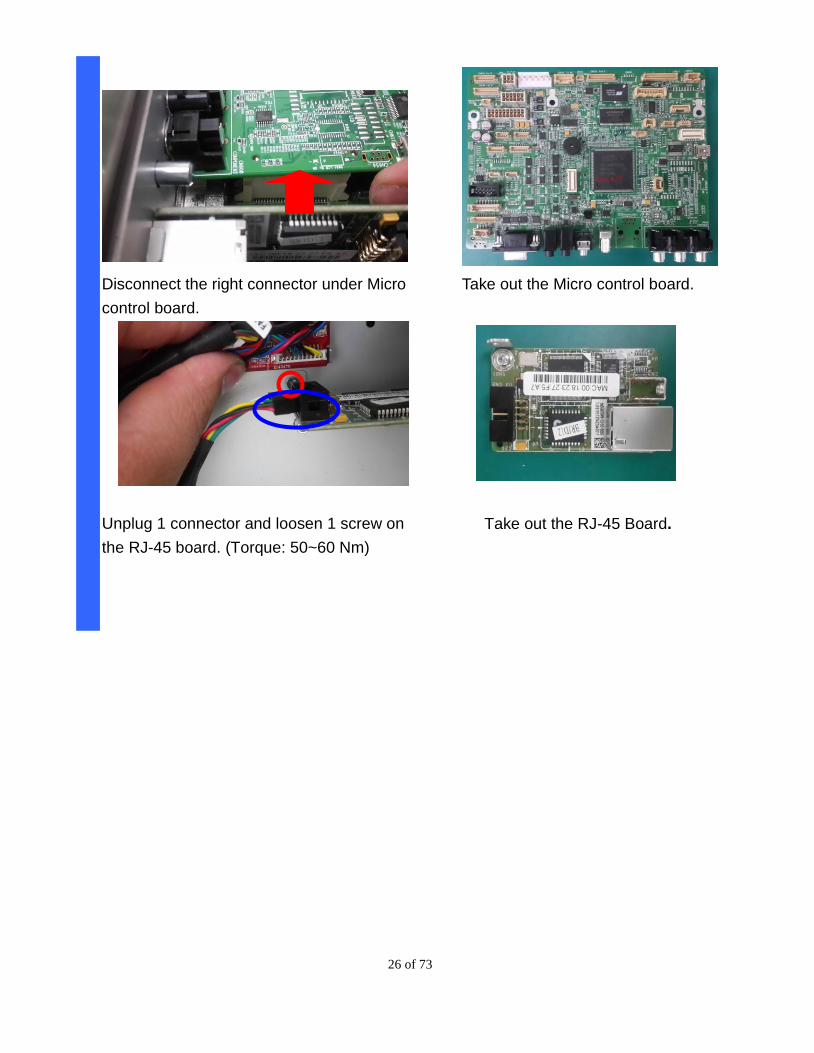
Disconnect the left connector under Micro
control board.
26 of 73
Disconnect the right connector under Micro
control board.
Take out the Micro control board.
Unplug 1 connector and loosen 1 screw on
the RJ-45 board. (Torque: 50~60 Nm)
Take out the RJ-45 Board.
27 of 73
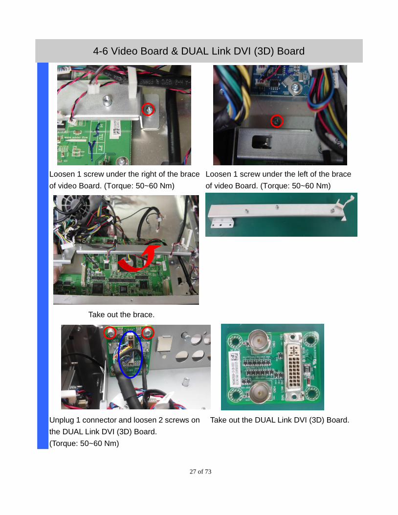
4-6 Video Board & DUAL Link DVI (3D) Board
Loosen 1 screw under the right of the brace
of video Board. (Torque: 50~60 Nm)
Loosen 1 screw under the left of the brace
of video Board. (Torque: 50~60 Nm)
Take out the brace.
Unplug 1 connector and loosen 2 screws on
the DUAL Link DVI (3D) Board.
(Torque: 50~60 Nm)
Take out the DUAL Link DVI (3D) Board.
28 of 73
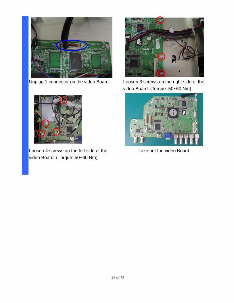
Unplug 1 connector on the video Board. Loosen 3 screws on the right side of the
video Board. (Torque: 50~60 Nm)
Loosen 4 screws on the left side of the
video Board. (Torque: 50~60 Nm)
Take out the video Board.
29 of 73
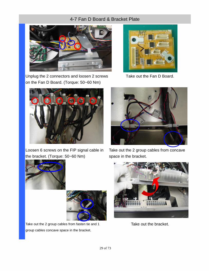
4-7 Fan D Board & Bracket Plate
Unplug the 2 connectors and loosen 2 screws
on the Fan D Board. (Torque: 50~60 Nm)
Take out the Fan D Board.
Loosen 6 screws on the FIP signal cable in
the bracket. (Torque: 50~60 Nm)
Take out the 2 group cables from concave
space in the bracket.
Take out the 2 group cables from fasten tie and 1
group cables concave space in the bracket.
Take out the bracket.
30 of 73
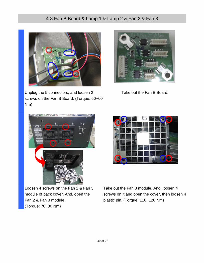
4-8 Fan B Board & Lamp 1 & Lamp 2 & Fan 2 & Fan 3
Unplug the 5 connectors, and loosen 2
screws on the Fan B Board. (Torque: 50~60
Nm)
Take out the Fan B Board.
Loosen 4 screws on the Fan 2 & Fan 3
module of back cover. And, open the
Fan 2 & Fan 3 module.
(Torque: 70~80 Nm)
Take out the Fan 3 module. And, loosen 4
screws on it and open the cover, then loosen 4
plastic pin. (Torque: 110~120 Nm)
31 of 73
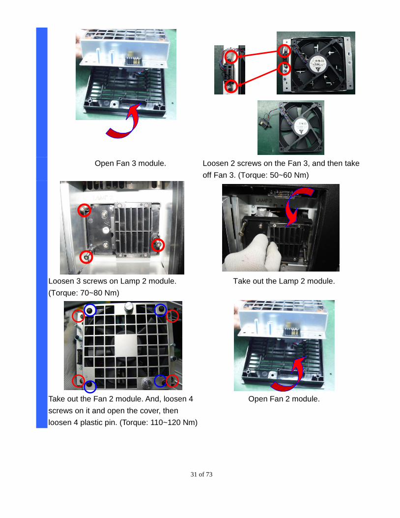
Open Fan 3 module. Loosen 2 screws on the Fan 3, and then take
off Fan 3. (Torque: 50~60 Nm)
Loosen 3 screws on Lamp 2 module.
(Torque: 70~80 Nm)
Take out the Lamp 2 module.
Take out the Fan 2 module. And, loosen 4
screws on it and open the cover, then
loosen 4 plastic pin. (Torque: 110~120 Nm)
Open Fan 2 module.
32 of 73
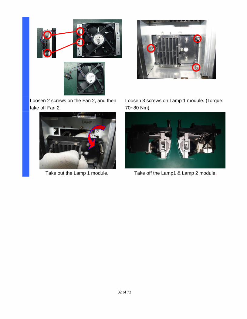
Loosen 2 screws on the Fan 2, and then
take off Fan 2.
Loosen 3 screws on Lamp 1 module. (Torque:
70~80 Nm)
Take out the Lamp 1 module. Take off the Lamp1 & Lamp 2 module.
33 of 73
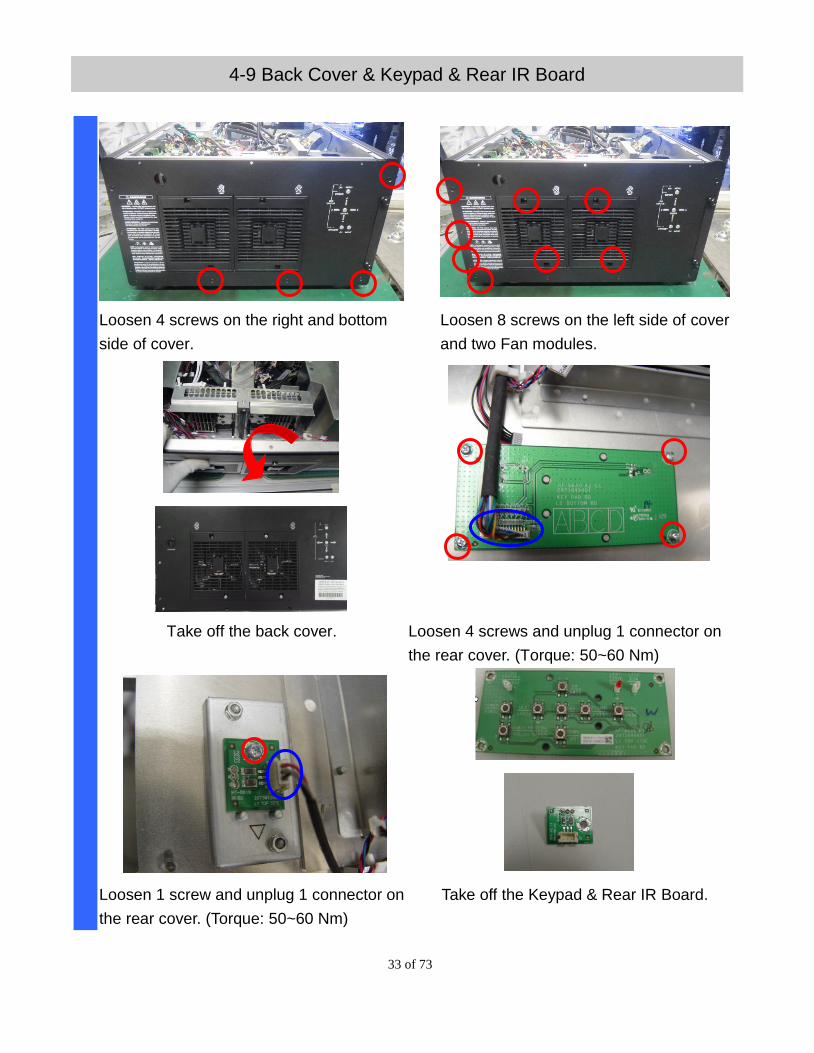
4-9 Back Cover & Keypad & Rear IR Board
Loosen 4 screws on the right and bottom
side of cover.
Loosen 8 screws on the left side of cover
and two Fan modules.
Take off the back cover. Loosen 4 screws and unplug 1 connector on
the rear cover. (Torque: 50~60 Nm)
Loosen 1 screw and unplug 1 connector on
the rear cover. (Torque: 50~60 Nm)
Take off the Keypad & Rear IR Board.
34 of 73
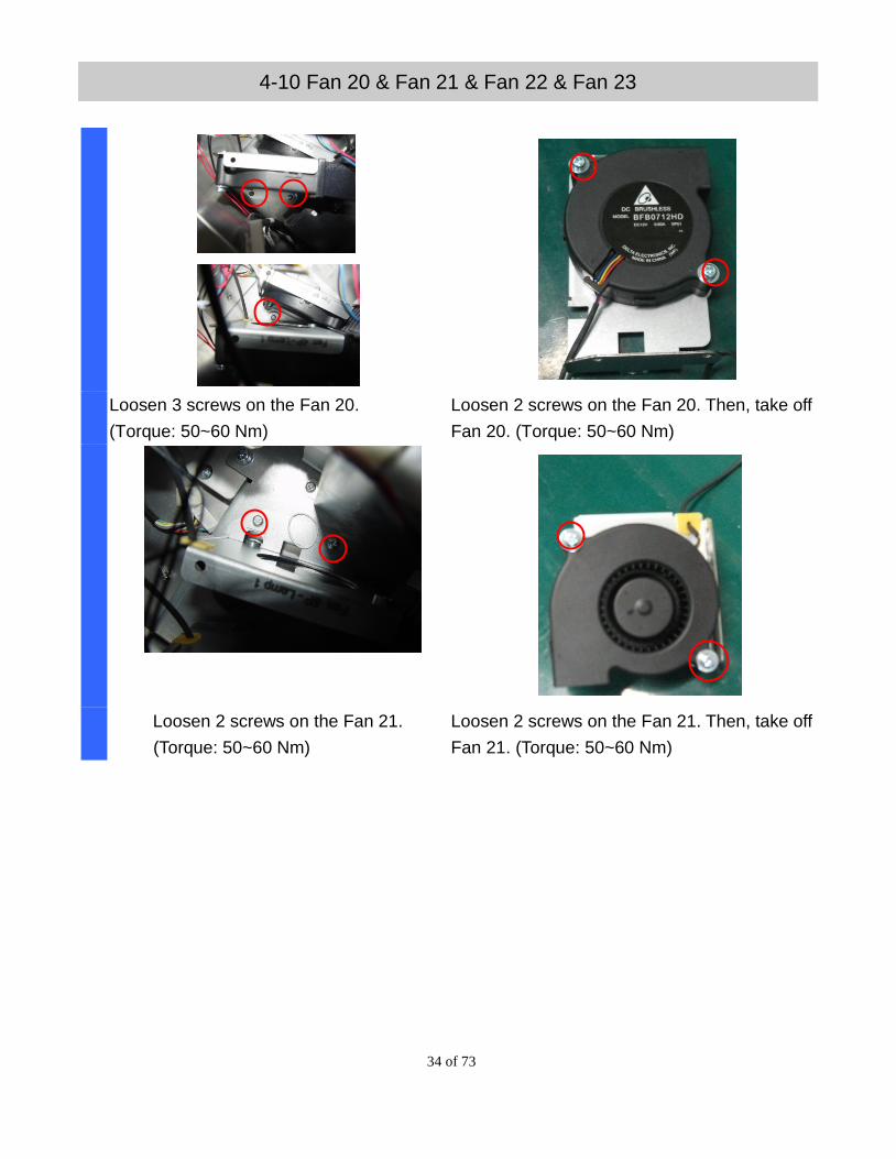
4-10 Fan 20 & Fan 21 & Fan 22 & Fan 23
Loosen 3 screws on the Fan 20.
(Torque: 50~60 Nm)
Loosen 2 screws on the Fan 20. Then, take off
Fan 20. (Torque: 50~60 Nm)
Loosen 2 screws on the Fan 21.
(Torque: 50~60 Nm)
Loosen 2 screws on the Fan 21. Then, take off
Fan 21. (Torque: 50~60 Nm)
35 of 73
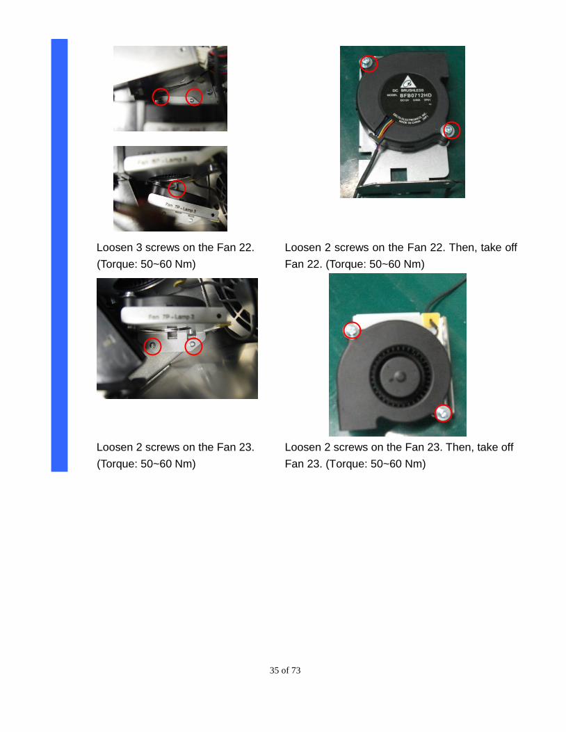
Loosen 3 screws on the Fan 22.
(Torque: 50~60 Nm)
Loosen 2 screws on the Fan 22. Then, take off
Fan 22. (Torque: 50~60 Nm)
Loosen 2 screws on the Fan 23.
(Torque: 50~60 Nm)
Loosen 2 screws on the Fan 23. Then, take off
Fan 23. (Torque: 50~60 Nm)
36 of 73
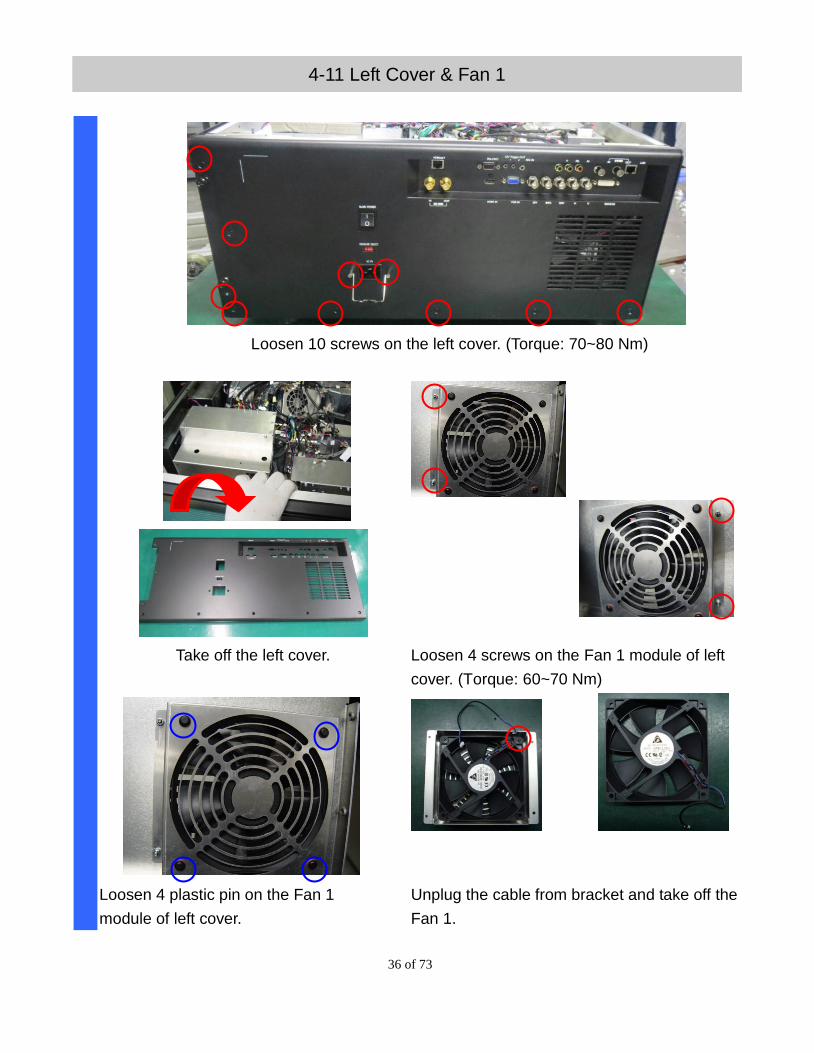
4-11 Left Cover & Fan 1
Loosen 10 screws on the left cover. (Torque: 70~80 Nm)
Take off the left cover. Loosen 4 screws on the Fan 1 module of left
cover. (Torque: 60~70 Nm)
Loosen 4 plastic pin on the Fan 1
module of left cover.
Unplug the cable from bracket and take off the
Fan 1.
37 of 73
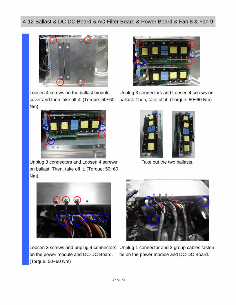
4-12 Ballast & DC-DC Board & AC Filter Board & Power Board & Fan 8 & Fan 9
Loosen 4 screws on the ballast module
cover and then take off it. (Torque: 50~60
Nm)
Unplug 3 connectors and Loosen 4 screws on
ballast. Then, take off it. (Torque: 50~60 Nm)
Unplug 3 connectors and Loosen 4 screws
on ballast. Then, take off it. (Torque: 50~60
Nm)
Take out the two ballasts.
Loosen 3 screws and unplug 4 connectors
on the power module and DC-DC Board.
(Torque: 50~60 Nm)
Unplug 1 connector and 2 group cables fasten
tie on the power module and DC-DC Board.
38 of 73
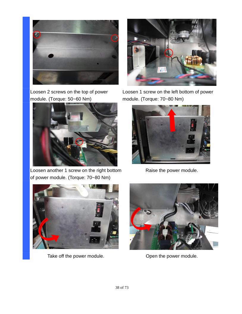
Loosen 2 screws on the top of power
module. (Torque: 50~60 Nm)
Loosen 1 screw on the left bottom of power
module. (Torque: 70~80 Nm)
Loosen another 1 screw on the right bottom
of power module. (Torque: 70~80 Nm)
Raise the power module.
Take off the power module. Open the power module.
39 of 73
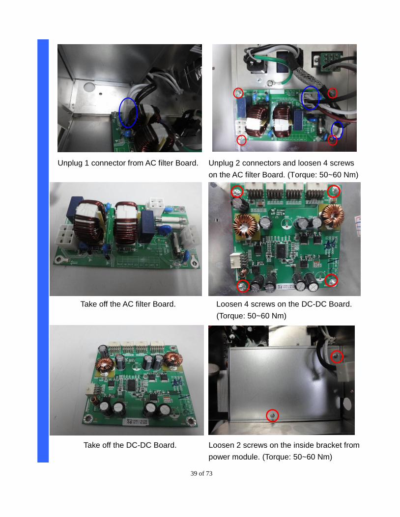
Unplug 1 connector from AC filter Board. Unplug 2 connectors and loosen 4 screws
on the AC filter Board. (Torque: 50~60 Nm)
Take off the AC filter Board. Loosen 4 screws on the DC-DC Board.
(Torque: 50~60 Nm)
Take off the DC-DC Board. Loosen 2 screws on the inside bracket from
power module. (Torque: 50~60 Nm)
40 of 73
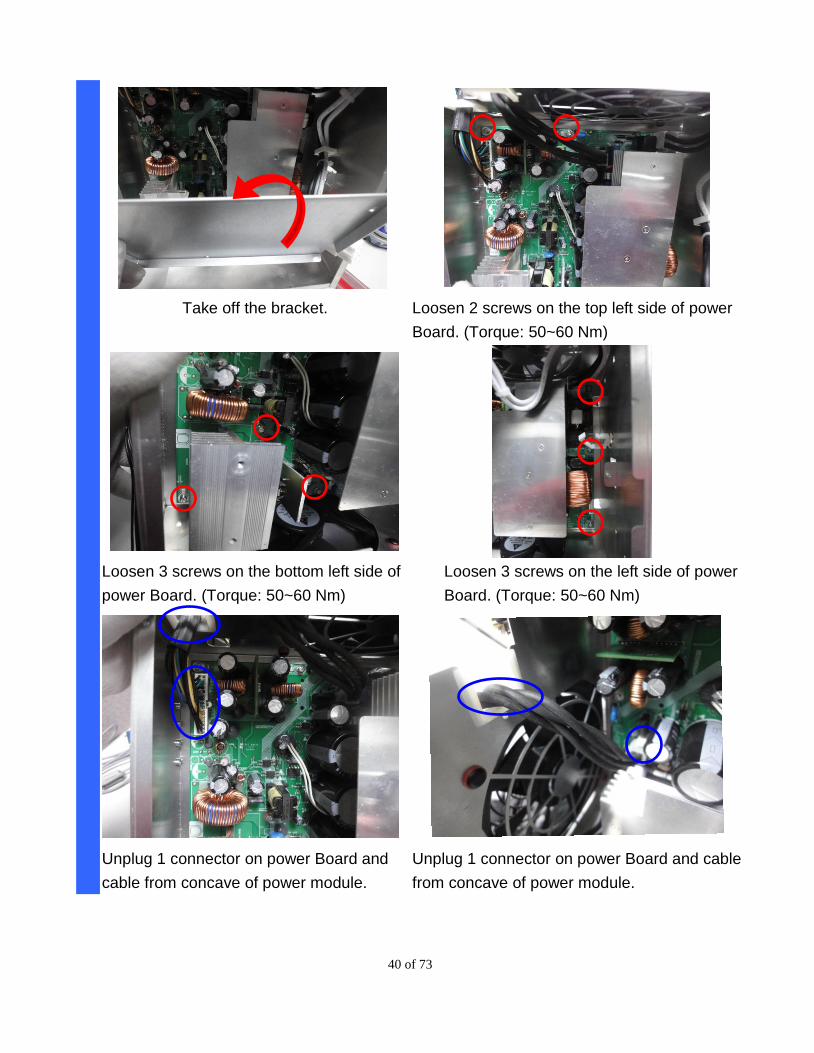
Take off the bracket. Loosen 2 screws on the top left side of power
Board. (Torque: 50~60 Nm)
Loosen 3 screws on the bottom left side of
power Board. (Torque: 50~60 Nm)
Loosen 3 screws on the left side of power
Board. (Torque: 50~60 Nm)
Unplug 1 connector on power Board and
cable from concave of power module.
Unplug 1 connector on power Board and cable
from concave of power module.
41 of 73
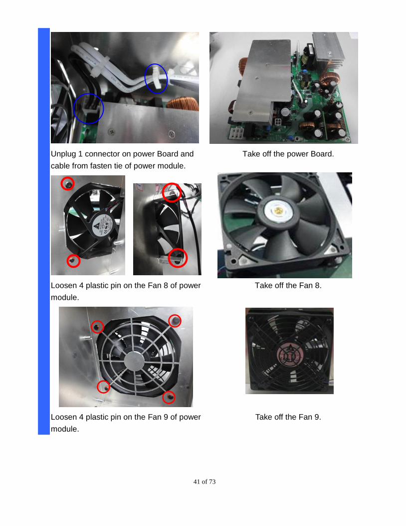
Unplug 1 connector on power Board and
cable from fasten tie of power module.
Take off the power Board.
Loosen 4 plastic pin on the Fan 8 of power
module.
Take off the Fan 8.
Loosen 4 plastic pin on the Fan 9 of power
module.
Take off the Fan 9.
42 of 73
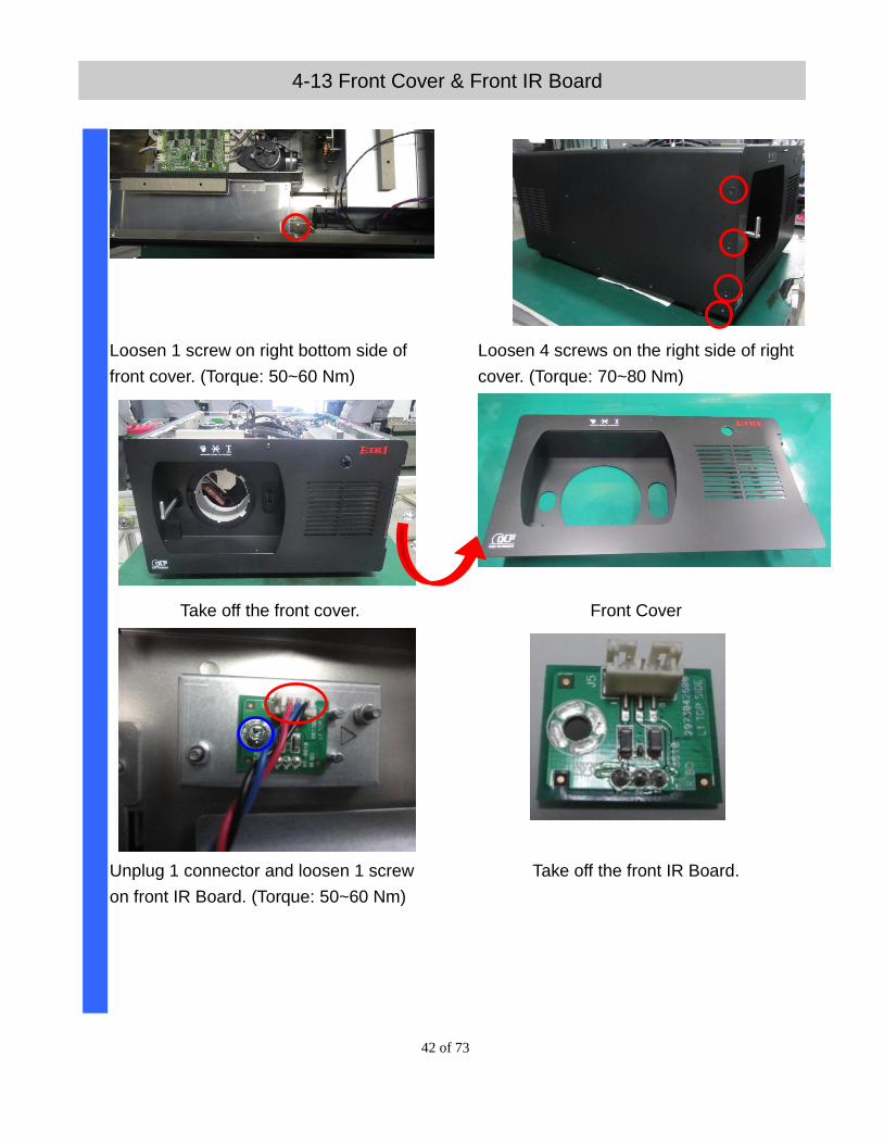
4-13 Front Cover & Front IR Board
Loosen 1 screw on right bottom side of
front cover. (Torque: 50~60 Nm)
Loosen 4 screws on the right side of right
cover. (Torque: 70~80 Nm)
Take off the front cover. Front Cover
Unplug 1 connector and loosen 1 screw
on front IR Board. (Torque: 50~60 Nm)
Take off the front IR Board.
43 of 73
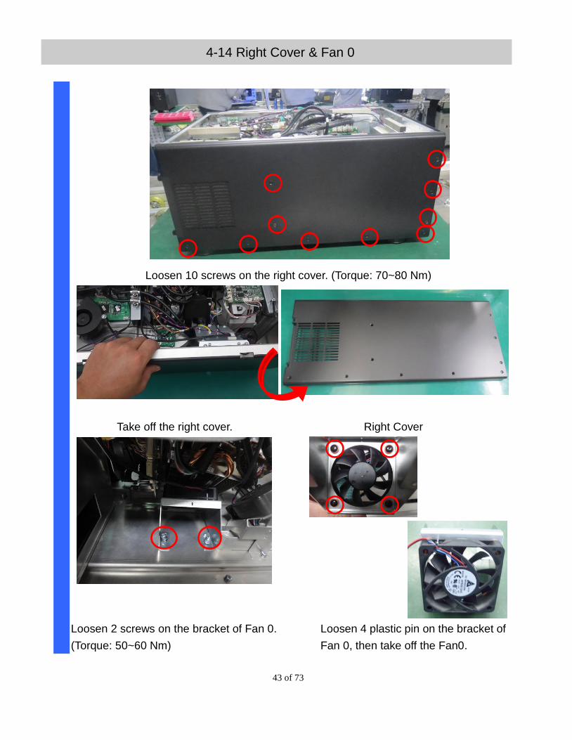
4-14 Right Cover & Fan 0
Loosen 10 screws on the right cover. (Torque: 70~80 Nm)
Take off the right cover. Right Cover
Loosen 2 screws on the bracket of Fan 0.
(Torque: 50~60 Nm)
Loosen 4 plastic pin on the bracket of
Fan 0, then take off the Fan0.
44 of 73
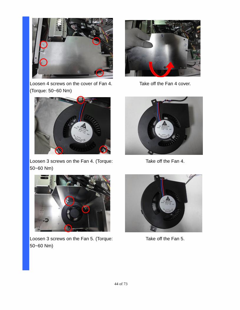
Loosen 4 screws on the cover of Fan 4.
(Torque: 50~60 Nm)
Take off the Fan 4 cover.
Loosen 3 screws on the Fan 4. (Torque:
50~60 Nm)
Take off the Fan 4.
Loosen 3 screws on the Fan 5. (Torque:
50~60 Nm)
Take off the Fan 5.
45 of 73
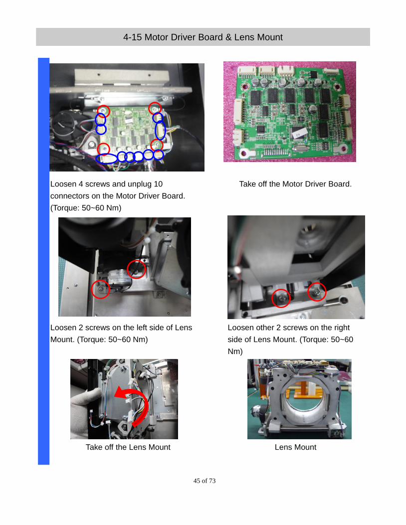
4-15 Motor Driver Board & Lens Mount
Loosen 4 screws and unplug 10
connectors on the Motor Driver Board.
(Torque: 50~60 Nm)
Take off the Motor Driver Board.
Loosen 2 screws on the left side of Lens
Mount. (Torque: 50~60 Nm)
Loosen other 2 screws on the right
side of Lens Mount. (Torque: 50~60
Nm)
Take off the Lens Mount
Lens Mount
46 of 73
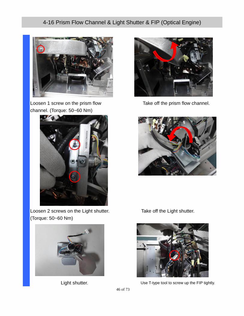
4-16 Prism Flow Channel & Light Shutter & FIP (Optical Engine)
Loosen 1 screw on the prism flow
channel. (Torque: 50~60 Nm)
Take off the prism flow channel.
Loosen 2 screws on the Light shutter.
(Torque: 50~60 Nm)
Take off the Light shutter.
Light shutter. Use T-type tool to screw up the FIP tightly.

47 of 73
Loosen first screw on the bottom side of
FIP. (Torque: 70~80 Nm)
Loosen second screw on the bottom side of
FIP. (Torque: 70~80 Nm)
Loosen third screw on the bottom side of
FIP. (Torque: 70~80 Nm)
Take off the FIP.
FIP (Optical Engine)
48 of 73
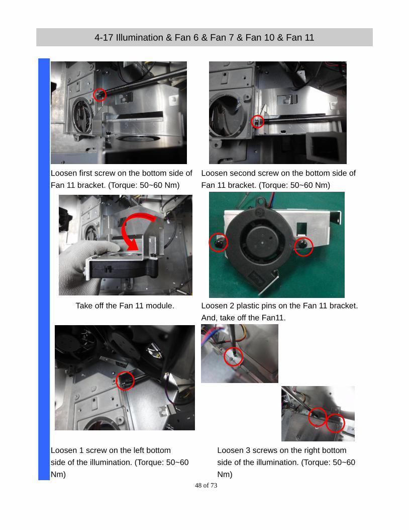
4-17 Illumination & Fan 6 & Fan 7 & Fan 10 & Fan 11
Loosen first screw on the bottom side of
Fan 11 bracket. (Torque: 50~60 Nm)
Loosen second screw on the bottom side of
Fan 11 bracket. (Torque: 50~60 Nm)
Take off the Fan 11 module. Loosen 2 plastic pins on the Fan 11 bracket.
And, take off the Fan11.
Loosen 1 screw on the left bottom
side of the illumination. (Torque: 50~60
Nm)
Loosen 3 screws on the right bottom
side of the illumination. (Torque: 50~60
Nm)
49 of 73
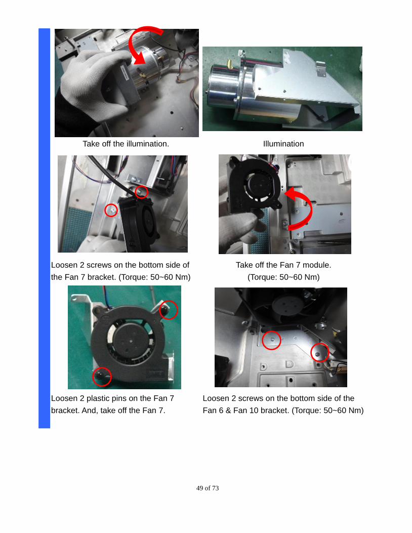
Take off the illumination. Illumination
Loosen 2 screws on the bottom side of
the Fan 7 bracket. (Torque: 50~60 Nm)
Take off the Fan 7 module.
(Torque: 50~60 Nm)
Loosen 2 plastic pins on the Fan 7
bracket. And, take off the Fan 7.
Loosen 2 screws on the bottom side of the
Fan 6 & Fan 10 bracket. (Torque: 50~60 Nm)
50 of 73
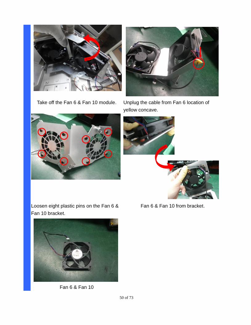
Take off the Fan 6 & Fan 10 module. Unplug the cable from Fan 6 location of
yellow concave.
Loosen eight plastic pins on the Fan 6 &
Fan 10 bracket.
Fan 6 & Fan 10 from bracket.
Fan 6 & Fan 10

51 of 73
5. ADJUSTMENT
5-1. Folding Mirror Adjusting
1. Use 7 mm Hex-Sleeve screwdriver to adjust.
2. Check the full-white image where color band is, and slight adjust fixed-nut to
remove it.
3. When finish adjusted, add TB1401B glue on the nuts to fix it.
A
C
B
A
C
B
(1) To adjust nut A to move the image vertically
(2) To adjust nut B to move the image horizontally
(3) Nut C is to confirm the reflector default position (The distance from bracket to top of screw
is 8.6 ± 0.2)
52 of 73
5-2. Focus Adjusting
(A)
(B)
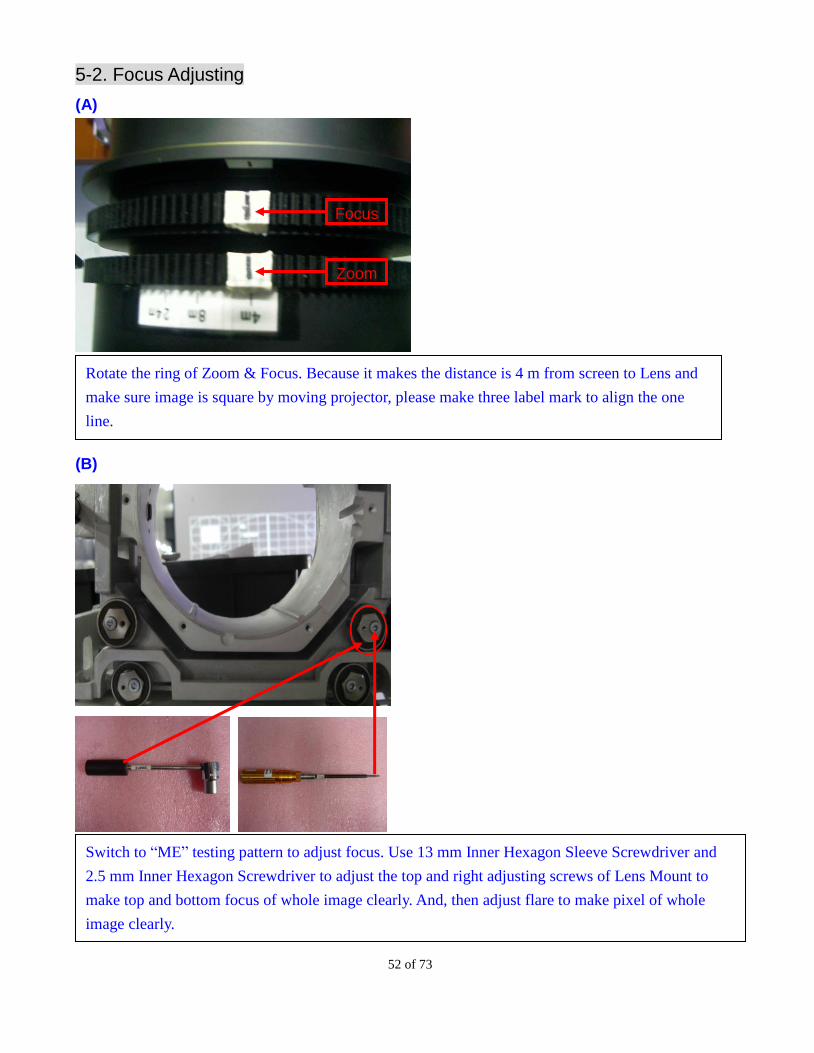
Rotate the ring of Zoom & Focus. Because it makes the distance is 4 m from screen to Lens and
make sure image is square by moving projector, please make three label mark to align the one
line.
Focus
Zoom
Switch to “ME” testing pattern to adjust focus. Use 13 mm Inner Hexagon Sleeve Screwdriver and
2.5 mm Inner Hexagon Screwdriver to adjust the top and right adjusting screws of Lens Mount to
make top and bottom focus of whole image clearly. And, then adjust flare to make pixel of whole
image clearly.
53 of 73
(C)
(D)
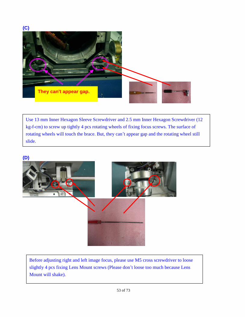
They can't appear gap.
Use 13 mm Inner Hexagon Sleeve Screwdriver and 2.5 mm Inner Hexagon Screwdriver (12
kg-f-cm) to screw up tightly 4 pcs rotating wheels of fixing focus screws. The surface of
rotating wheels will touch the brace. But, they can’t appear gap and the rotating wheel still
slide.
Before adjusting right and left image focus, please use M5 cross screwdriver to loose
slightly 4 pcs fixing Lens Mount screws (Please don’t loose too much because Lens
Mount will shake).
54 of 73
(E)
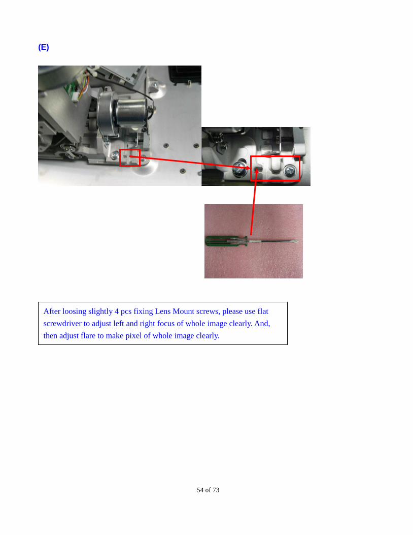
After loosing slightly 4 pcs fixing Lens Mount screws, please use flat
screwdriver to adjust left and right focus of whole image clearly. And,
then adjust flare to make pixel of whole image clearly.

55 of 73
(F)
(G)
Please use 3 mm inner hexagon screwdriver to adjust front and back
focus of whole image clearly. And, then adjust flare to make pixel of
whole image clearly.
After adjusting all position focus of whole image, please use M5 cross
screwdriver (10 kg-f-cm) to screw up tightly 4 pcs fixing Lens Mount
screws. If the focus move or fail, while you screw up Lens Mount.
Please re-adjust all steps again.
56 of 73
(H)
(I)
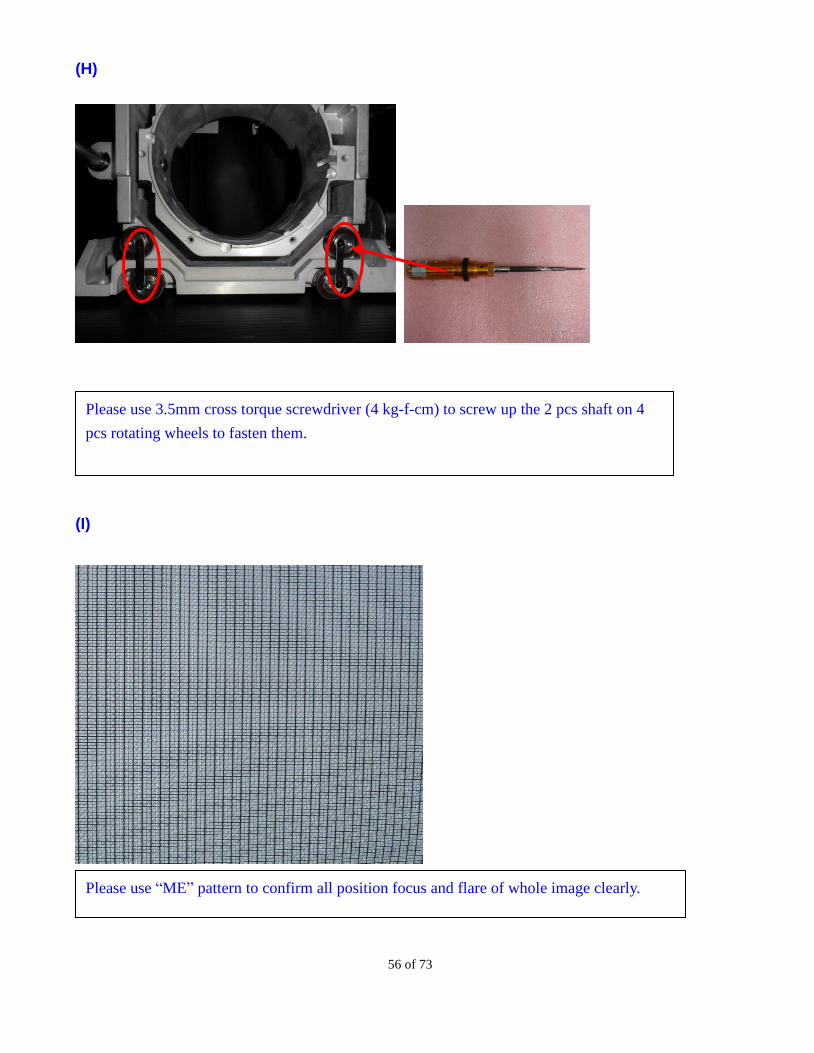
Please use “ME” pattern to confirm all position focus and flare of whole image clearly.
Please use 3.5mm cross torque screwdriver (4 kg-f-cm) to screw up the 2 pcs shaft on 4
pcs rotating wheels to fasten them.
57 of 73
6. MAINTENANCE
6-1 Cleaning the projector
6-1-1 Cleaning the Cabinet
Refer to the following guide to clean the projector cabinet.
a. Wipe off dust with a clean dampened cloth.
b. Moisten the cloth with warm water and mild detergent and wipe the cabinet.
c. Rinse all detergent from the cloth and wipe the projector again.
CAUTION
To prevent discoloration or fading of the case, do not use abrasive
alcohol-based cleaners.
6-1-2 Cleaning the Lens
Refer to the following guide to clean the projector lens.
a. Apply a little optic lens cleaner to a clean, lint free cloth (do not apply the cleaner directly to the lens).
b. Lightly wipe the lens in a circular motion.
CAUTION
Do not use abrasive cleaners or solvents.
To prevent discoloration or fading, avoid getting cleaner on the projector
case.
6-1-3 Replace the Filters
Dirty filter may reduce the air flowing into the projector and the temperature in the projector may rise as a
result. This may activate the protection mechanism or damage the components. Suggest changing the filter
each 2,000 hours. If the environment is quite dirty, you can check the filter status each 500 hours. If the filter
is still too dirty, please directly exchange it.
58 of 73
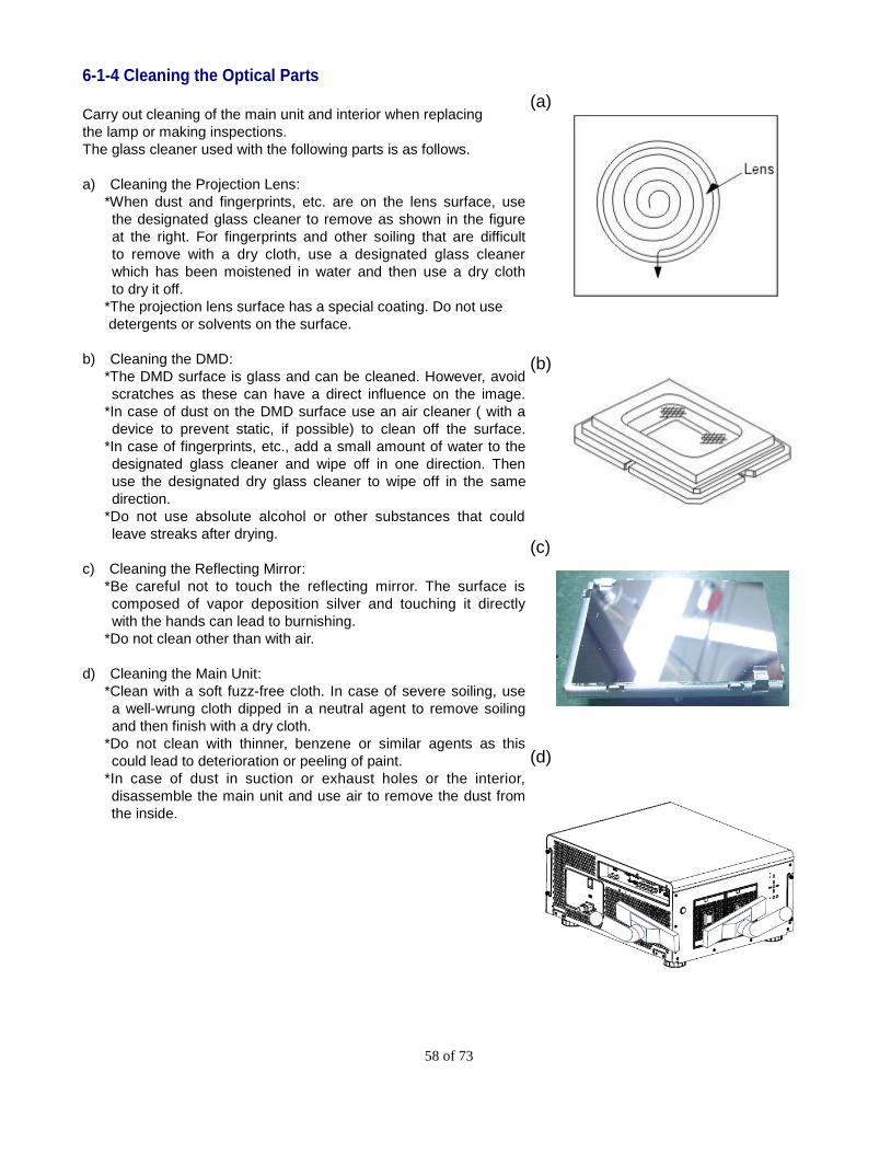
6-1-4 Cleaning the Optical Parts
Carry out cleaning of the main unit and interior when replacing
the lamp or making inspections.
The glass cleaner used with the following parts is as follows.
a) Cleaning the Projection Lens:
*When dust and fingerprints, etc. are on the lens surface, use
the designated glass cleaner to remove as shown in the figure
at the right. For fingerprints and other soiling that are difficult
to remove with a dry cloth, use a designated glass cleaner
which has been moistened in water and then use a dry cloth
to dry it off.
*The projection lens surface has a special coating. Do not use
detergents or solvents on the surface.
b) Cleaning the DMD:
*The DMD surface is glass and can be cleaned. However, avoid
scratches as these can have a direct influence on the image.
*In case of dust on the DMD surface use an air cleaner ( with a
device to prevent static, if possible) to clean off the surface.
*In case of fingerprints, etc., add a small amount of water to the
designated glass cleaner and wipe off in one direction. Then
use the designated dry glass cleaner to wipe off in the same
direction.
*Do not use absolute alcohol or other substances that could
leave streaks after drying.
c) Cleaning the Reflecting Mirror:
*Be careful not to touch the reflecting mirror. The surface is
composed of vapor deposition silver and touching it directly
with the hands can lead to burnishing.
*Do not clean other than with air.
d) Cleaning the Main Unit:
*Clean with a soft fuzz-free cloth. In case of severe soiling, use
a well-wrung cloth dipped in a neutral agent to remove soiling
and then finish with a dry cloth.
*Do not clean with thinner, benzene or similar agents as this
could lead to deterioration or peeling of paint.
*In case of dust in suction or exhaust holes or the interior,
disassemble the main unit and use air to remove the dust from
the inside.
(a)
(b)
(c)
(d)
59 of 73
6-2 Replacing Consumable Parts
During the course of normal usage, consumable parts become worn out resulting in reduced performance. The
following guides detail how to replace the various consumable parts within the projector quickly and safely.
Before replacing any of the parts, please take note of the following:
a. Ensure that the projector is turned off and disconnected from the power supply.
b. Ensure that the projector is in a clean, stable position before replacing parts.
c. Allow at least one hour after shutdown for the projector to cool before attempting to replace any
consumable parts.
d. Do not interchange Lamp 1 and Lamp 2 after the projector has been used once.
e. Doing so will not allow the projector to display the correct lamp usage hours.
60 of 73
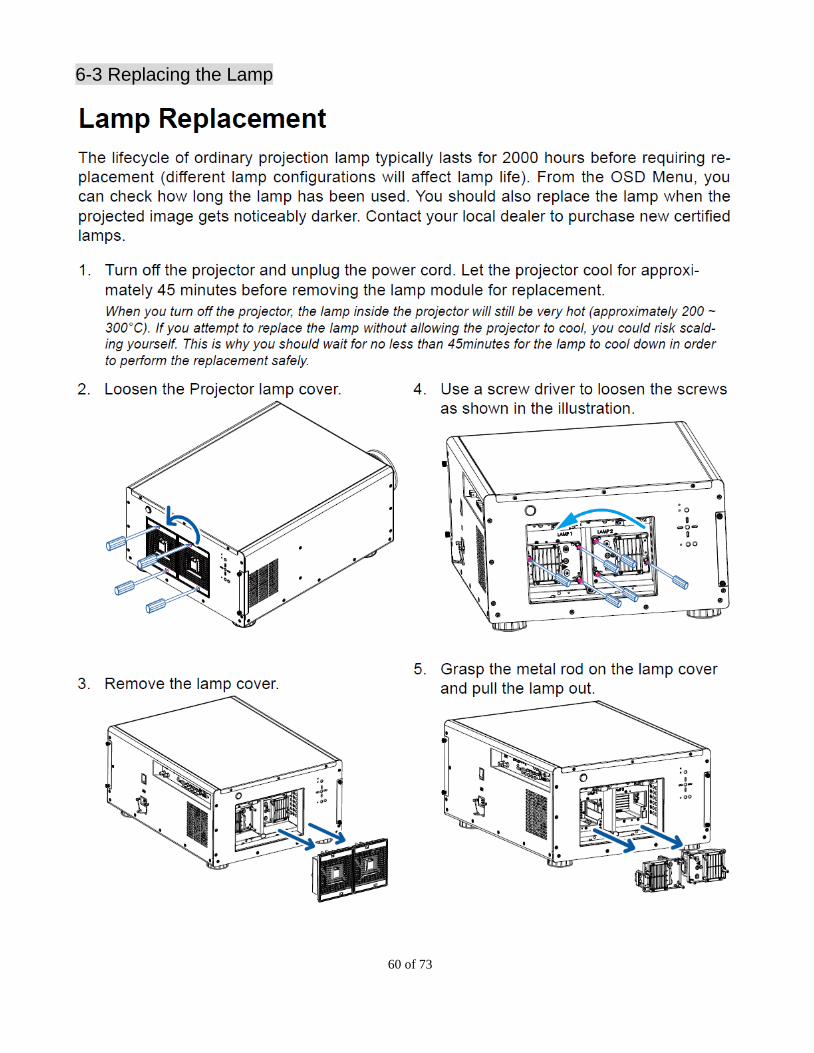
6-3 Replacing the Lamp
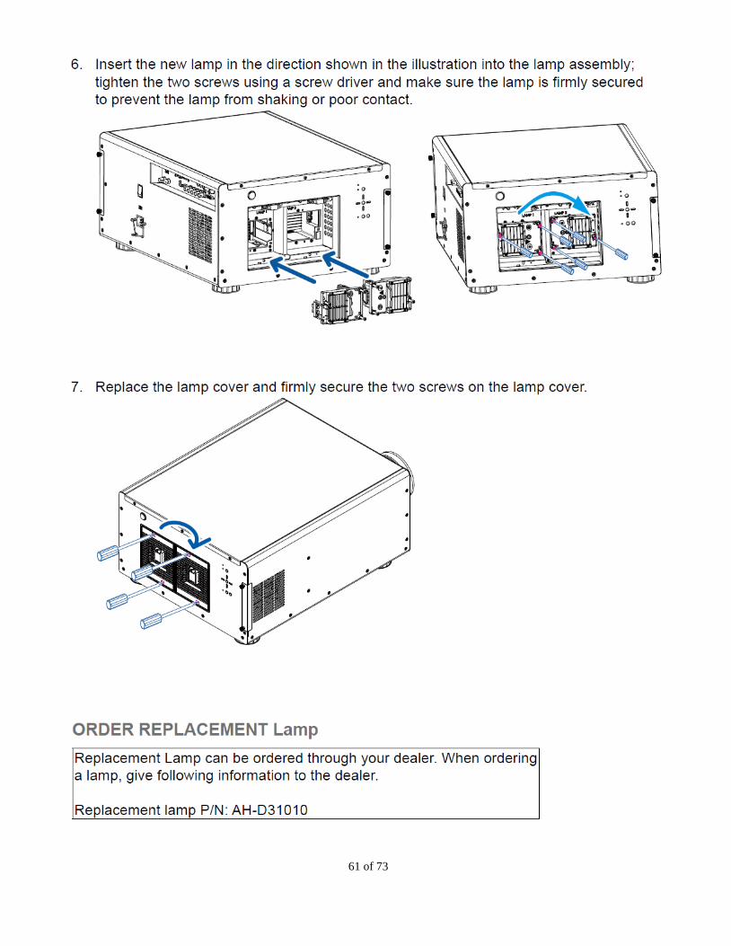
61 of 73
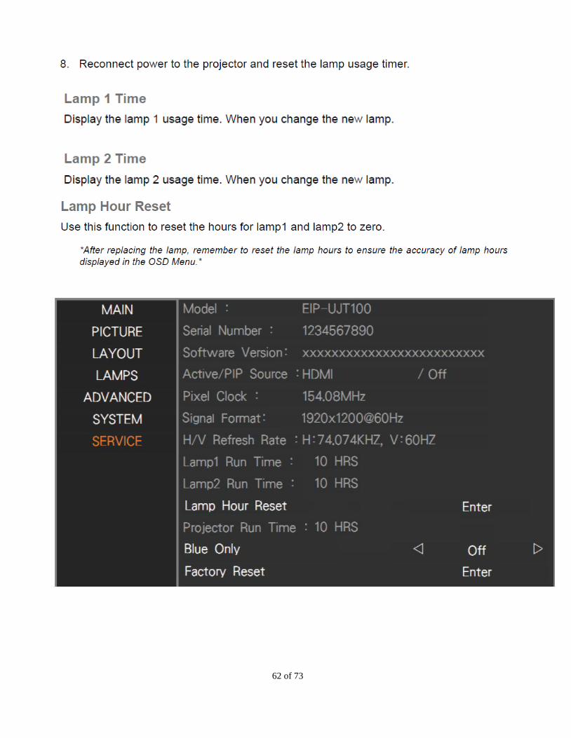
62 of 73

63 of 73
6-4 Replacing the Filter

64 of 73
Replacement Filter (Side Rear): 3243270701
Replacement Filter (Front) : 3243411700
65 of 73
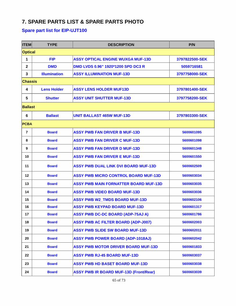
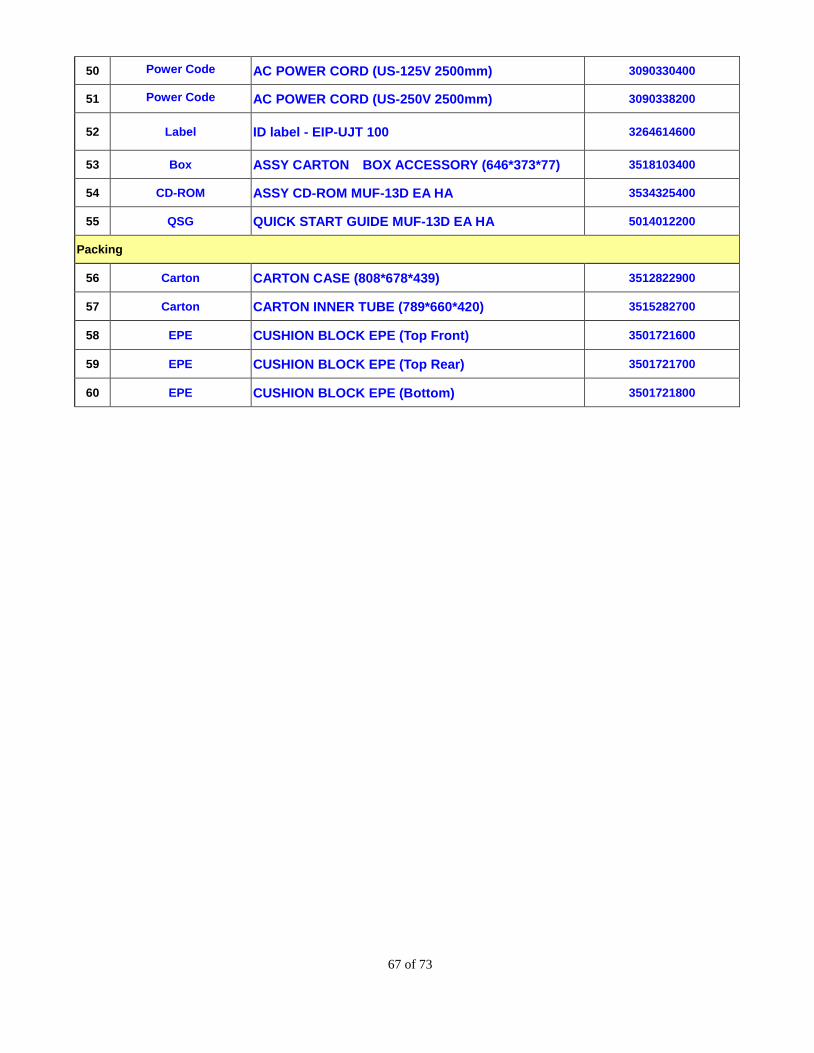
7. SPARE PARTS LIST & SPARE PARTS PHOTO
Spare part list for EIP-UJT100
ITEM TYPE DESCRIPTION P/N
Optical
1 FIP ASSY OPTICAL ENGINE WUXGA MUF-13D 3797822500-SEK
2 DMD DMD LVDS 0.96" 1920*1200 SPD DC3 R 5059716581
3 Illumination ASSY ILLUMINATION MUF-13D 3797758000-SEK
Chassis
4 Lens Holder ASSY LENS HOLDER MUF13D 3797801400-SEK
5 Shutter ASSY UNIT SHUTTER MUF-13D 3797758200-SEK
Ballast
6 Ballast UNIT BALLAST 465W MUF-13D 3797803300-SEK
PCBA
7 Board ASSY PWB FAN DRIVER B MUF-13D 5600601095
8 Board ASSY PWB FAN DRIVER C MUF-13D 5600601098
9 Board ASSY PWB FAN DRIVER D MUF-13D 5600601348
10 Board ASSY PWB FAN DRIVER E MUF-13D 5600601550
11 Board ASSY PWB DUAL LINK DVI BOARD MUF-13D 5600602509
12 Board ASSY PWB MICRO CONTROL BOARD MUF-13D 5600603034
13 Board ASSY PWB MAIN FORNATTER BOARD MUF-13D 5600603035
14 Board ASSY PWB VIDEO BOARD MUF-13D 5600603036
15 Board ASSY PWB W2_TMDS BOARD MUF-13D 5600602106
16 Board ASSY PWB KEYPAD BOARD MUF-13D 5600601317
17 Board ASSY PWB DC-DC BOARD (ADP-75AJ A) 5600601786
18 Board ASSY PWB AC FILTER BOARD (ADP-J007) 5600602003
19 Board ASSY PWB SLIDE SW BOARD MUF-13D 5600602011
20 Board ASSY PWB POWER BOARD (ADP-1018AJ) 5600602042
21 Board ASSY PWB MOTOR DRIVER BOARD MUF-13D 5600601833
22 Board ASSY PWB RJ-45 BOARD MUF-13D 5600603037
23 Board ASSY PWB HD BASET BOARD MUF-13D 5600603038
24 Board ASSY PWB IR BOARD MUF-13D (Front/Rear) 5600603039
66 of 73
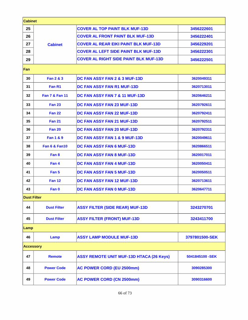
Cabinet
25
Cabinet
COVER AL TOP PAINT BLK MUF-13D 3456222601
26 COVER AL FRONT PAINT BLK MUF-13D 3456222401
27 COVER AL REAR EIKI PAINT BLK MUF-13D 3456229201
28 COVER AL LEFT SIDE PAINT BLK MUF-13D 3456222301
29 COVER AL RIGHT SIDE PAINT BLK MUF-13D 3456222501
Fan
30 Fan 2 & 3 DC FAN ASSY FAN 2 & 3 MUF-13D 3620049311
31 Fan R1 DC FAN ASSY FAN R1 MUF-13D 3620713011
32 Fan 7 & Fan 11 DC FAN ASSY FAN 7 & 11 MUF-13D 3620646211
33 Fan 23 DC FAN ASSY FAN 23 MUF-13D 3620792611
34 Fan 22 DC FAN ASSY FAN 22 MUF-13D 3620792411
35 Fan 21 DC FAN ASSY FAN 21 MUF-13D 3620792511
36 Fan 20 DC FAN ASSY FAN 20 MUF-13D 3620792311
37 Fan 1 & 9 DC FAN ASSY FAN 1 & 9 MUF-13D 3620049611
38 Fan 6 & Fan10 DC FAN ASSY FAN 6 MUF-13D 3620866511
39 Fan 8 DC FAN ASSY FAN 8 MUF-13D 3620017011
40 Fan 4 DC FAN ASSY FAN 4 MUF-13D 3620050411
41 Fan 5 DC FAN ASSY FAN 5 MUF-13D 3620050511
42 Fan 12 DC FAN ASSY FAN 12 MUF-13D 3620713611
43 Fan 0 DC FAN ASSY FAN 0 MUF-13D 3620647711
Dust Filter
44 Dust Filter ASSY FILTER (SIDE REAR) MUF-13D 3243270701
45 Dust Filter ASSY FILTER (FRONT) MUF-13D 3243411700
Lamp
46 Lamp ASSY LAMP MODULE MUF-13D 3797801500-SEK
Accessory
47 Remote ASSY REMOTE UNIT MUF-13D HTACA (26 Keys) 5041845100 -SEK
48 Power Code AC POWER CORD (EU 2500mm) 3090285300
49 Power Code AC POWER CORD (CN 2500mm) 3090316600
67 of 73
50 Power Code AC POWER CORD (US-125V 2500mm) 3090330400
51 Power Code AC POWER CORD (US-250V 2500mm) 3090338200
52 Label ID label - EIP-UJT 100 3264614600
53 Box ASSY CARTON BOX ACCESSORY (646*373*77) 3518103400
54 CD-ROM ASSY CD-ROM MUF-13D EA HA 3534325400
55 QSG QUICK START GUIDE MUF-13D EA HA 5014012200
Packing
56 Carton CARTON CASE (808*678*439) 3512822900
57 Carton CARTON INNER TUBE (789*660*420) 3515282700
58 EPE CUSHION BLOCK EPE (Top Front) 3501721600
59 EPE CUSHION BLOCK EPE (Top Rear) 3501721700
60 EPE CUSHION BLOCK EPE (Bottom) 3501721800
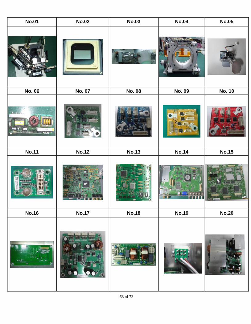
68 of 73
No.01 No.02 No.03 No.04 No.05
No. 06 No. 07 No. 08 No. 09 No. 10
No.11 No.12 No.13 No.14 No.15
No.16 No.17 No.18 No.19 No.20
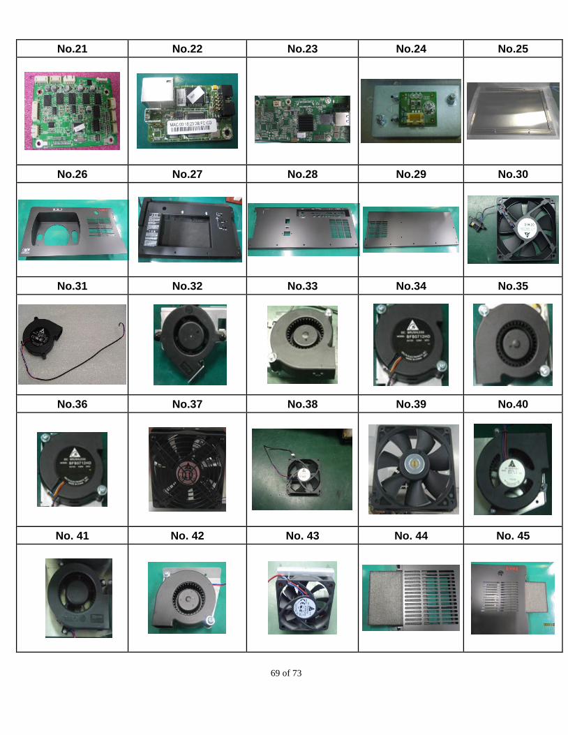
69 of 73
No.21 No.22 No.23 No.24 No.25
No.26 No.27 No.28 No.29 No.30
No.31 No.32 No.33 No.34 No.35
No.36 No.37 No.38 No.39 No.40
No. 41 No. 42 No. 43 No. 44 No. 45
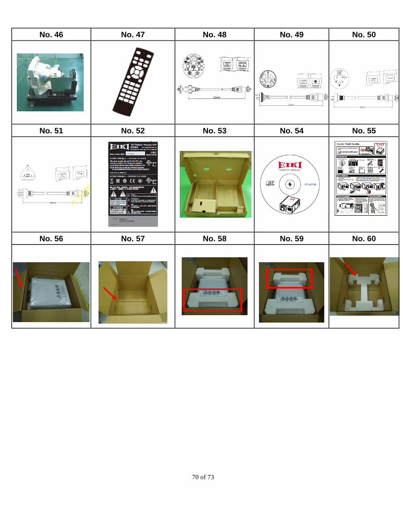
70 of 73
No. 46 No. 47 No. 48 No. 49 No. 50
No. 51 No. 52 No. 53 No. 54 No. 55
No. 56 No. 57 No. 58 No. 59 No. 60
71 of 73
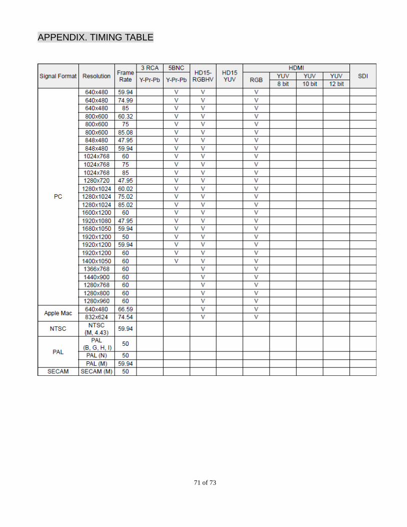
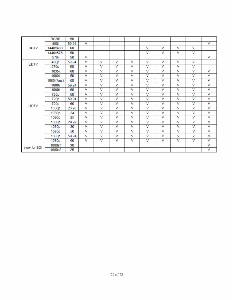
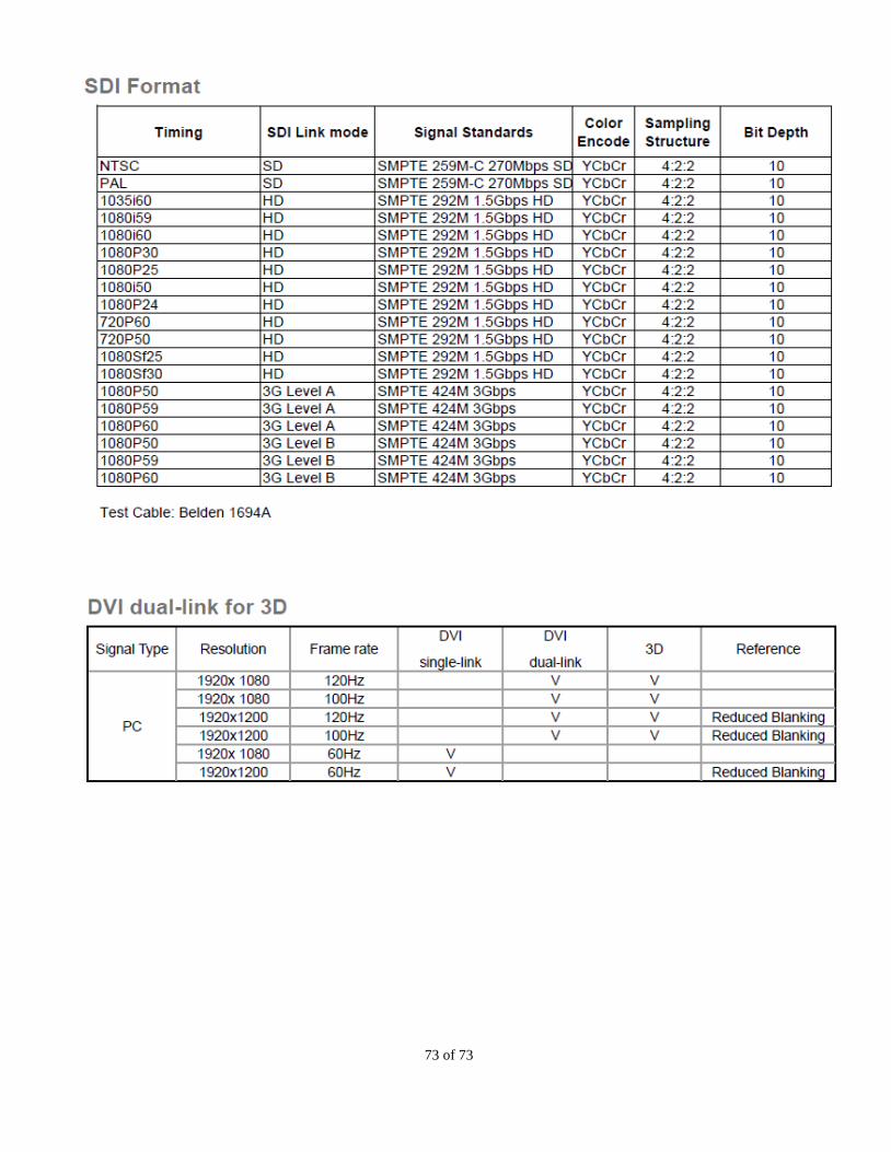
APPENDIX. TIMING TABLE
72 of 73
73 of 73