Embed Size (px)
Citation preview
No. 52076Dec. 2002
AV-20N83AV-21D83
BASIC CHASSIS
CH
COPYRIGHT © 2002 VICTOR COMPANY OF JAPAN, LTD.
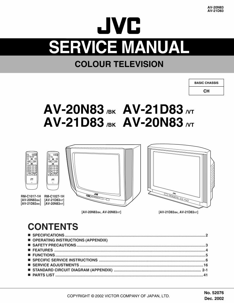
SERVICE MANUALCOLOUR TELEVISION
RM-C1027-1H[AV-21D83/VT][AV-20N83/VT]
[AV-21D83/BK, AV-21D83/VT][AV-20N83/BK, AV-20N83/VT]
AV-20N83 /BK
AV-21D83 /BK
AV-21D83 /VT
AV-20N83 /VT
MUTINGPICTUREBOOSTER
OFFTIMER
ECOSENSOR
PICTUREMODE
CHANNELSCAN
SYSTEMCOLOUR SOUND
MENU
CHANNEL
RETURN+
POWER
DISPLAY
TV/VIDEO
VOLUME
1 2 3
4 5 6
7 8 9
0 -/--
CINEMASURROUND
/
TV
RM-C1017
MUTINGPICTUREBOOSTER
OFFTIMER
ECOSENSOR
PICTUREMODE
CHANNELSCAN
SYSTEMCOLOUR SOUND
MENU
CHANNEL
RETURN+
POWER
DISPLAY
TV/VIDEO
VOLUME
1 2 3
4 5 6
7 8 9
0 -/--
TV
RM-C1027
1 2
RM-C1017-1H[AV-20N83/BK][AV-21D83/BK]
CONTENTSa SPECIFICATIONS ....................................................................................................................................2a OPERATING INSTRUCTIONS (APPENDIX)a SAFETY PRECAUTIONS.........................................................................................................................3a FEATURES ..............................................................................................................................................4a FUNCTIONS.............................................................................................................................................5a SPECIFIC SERVICE INSTRUCTIONS ....................................................................................................6a SERVICE ADJUSTMENTS ....................................................................................................................16a STANDARD CIRCUIT DIAGRAM (APPENDIX) .................................................................................. 2-1a PARTS LIST ...........................................................................................................................................41
2 No. 52076
AV-20N83AV-21D83
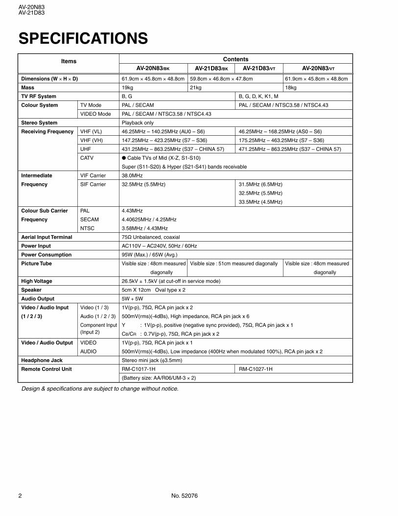
SPECIFICATIONS
Design & specifications are subject to change without notice.
Dimensions (W × H × D) 61.9cm × 45.8cm × 48.8cm 59.8cm × 46.8cm × 47.8cm 61.9cm × 45.8cm × 48.8cm
Mass 19kg 21kg 18kg
TV RF System B, G B, G, D, K, K1, M
Colour System TV Mode PAL / SECAM PAL / SECAM / NTSC3.58 / NTSC4.43
VIDEO Mode PAL / SECAM / NTSC3.58 / NTSC4.43
Stereo System Playback only
Receiving Frequency VHF (VL) 46.25MHz – 140.25MHz (AU0 – S6) 46.25MHz – 168.25MHz (AS0 – S6)
VHF (VH) 147.25MHz – 423.25MHz (S7 – S36) 175.25MHz – 463.25MHz (S7 – S36)
UHF 431.25MHz – 863.25MHz (S37 – CHINA 57) 471.25MHz – 863.25MHz (S37 – CHINA 57)
CATV Cable TVs of Mid (X-Z, S1-S10)
Super (S11-S20) & Hyper (S21-S41) bands receivable
Intermediate VIF Carrier 38.0MHz
Frequency SIF Carrier 32.5MHz (5.5MHz) 31.5MHz (6.5MHz)
32.5MHz (5.5MHz)
33.5MHz (4.5MHz)
Colour Sub Carrier PAL 4.43MHz
Frequency SECAM 4.40625MHz / 4.25MHz
NTSC 3.58MHz / 4.43MHz
Aerial Input Terminal 75Ø Unbalanced, coaxial
Power Input AC110V – AC240V, 50Hz / 60Hz
Power Consumption 95W (Max.) / 65W (Avg.)
Picture Tube Visible size : 48cm measured Visible size : 51cm measured diagonally Visible size : 48cm measured
diagonally diagonally
High Voltage 26.5kV ± 1.5kV (at cut-off in service mode)
Speaker 5cm X 12cm Oval type x 2
Audio Output 5W + 5W
Video / Audio Input Video (1 / 3) 1V(p-p), 75Ø, RCA pin jack x 2
(1 / 2 / 3) Audio (1 / 2 / 3) 500mV(rms)(-4dBs), High impedance, RCA pin jack x 6
Component Input Y : 1V(p-p), positive (negative sync provided), 75Ø, RCA pin jack x 1(Input 2) CB/CR : 0.7V(p-p), 75Ø, RCA pin jack x 2
Video / Audio Output VIDEO 1V(p-p), 75Ø, RCA pin jack x 1
AUDIO 500mV(rms)(-4dBs), Low impedance (400Hz when modulated 100%), RCA pin jack x 2
Headphone Jack Stereo mini jack (φ3.5mm)
Remote Control Unit RM-C1017-1H RM-C1027-1H
(Battery size: AA/R06/UM-3 × 2)
ItemsAV-21D83/BK
Contents
AV-20N83/BK AV-21D83/VT AV-20N83/VT
No. 52076 3
AV-20N83AV-21D83
SAFETY PRECAUTIONS1. The design of this product contains special hardware, many circuits
and components specially for safety purposes. For continued pro-tection, no changes should be made to the original design unlessauthorized in writing by the manufacturer. Replacement parts mustbe identical to those used in the original circuits. Service should beperformed by qualified personnel only.
2. Alterations of the design or circuitry of the products should not bemade. Any design alterations or additions will void the manufactur-er's warranty and will further relieve the manufacturer of responsi-bility for personal injury or property damage resulting therefrom.
3. Many electrical and mechanical parts in the products have specialsafety-related characteristics. These characteristics are often notevident from visual inspection nor can the protection afforded bythem necessarily be obtained by using replacement componentsrated for higher voltage, wattage, etc. Replacement parts which havethese special safety characteristics are identified in the parts list ofService manual. Electrical components having such features areidentified by shading on the schematics and by (!) on the partslist in Service manual. The use of a substitute replacement whichdoes not have the same safety characteristics as the recommendedreplacement part shown in the parts list of Service manual maycause shock, fire, or other hazards.
4. Don't short between the LIVE side ground and ISOLATED (NEU-TRAL) side ground or EARTH side ground when repairing.Some model's power circuit is partly different in the GND. The differ-ence of the GND is shown by the LIVE : ( ) side GND, the ISO-LATED (NEUTRAL) : ( ) side GND and EARTH : ( ) side GND.Don't short between the LIVE side GND and ISOLATED (NEUTRAL)side GND or EARTH side GND and never measure the LIVE sideGND and ISOLATED (NEUTRAL) side GND or EARTH side GNDat the same time with a measuring apparatus (oscilloscope etc.).If above note will not be kept, a fuse or any parts will be broken.
5. If any repair has been made to the chassis, it is recommended thatthe B1 setting should be checked or adjusted (See ADJUSTMENTOF B1 POWER SUPPLY).
6. The high voltage applied to the picture tube must conform with thatspecified in Service manual. Excessive high voltage can cause anincrease in X-Ray emission, arcing and possible component dam-age, therefore operation under excessive high voltage conditionsshould be kept to a minimum, or should be prevented. If severearcing occurs, remove the AC power immediately and determinethe cause by visual inspection (incorrect installation, cracked ormelted high voltage harness, poor soldering, etc.). To maintain theproper minimum level of soft X-Ray emission, components in thehigh voltage circuitry including the picture tube must be the exactreplacements or alternatives approved by the manufacturer of thecomplete product.
7. Do not check high voltage by drawing an arc. Use a high voltagemeter or a high voltage probe with a VTVM. Discharge the picturetube before attempting meter connection, by connecting a clip leadto the ground frame and connecting the other end of the lead througha 10kØ 2W resistor to the anode button.
8. When service is required, observe the original lead dress. Extraprecaution should be given to assure correct lead dress in the highvoltage circuit area. Where a short circuit has occurred, those com-ponents that indicate evidence of overheating should be replaced.Always use the manufacturer's replacement components.
9. Isolation Check(Safety for Electrical Shock Hazard)After re-assembling the product, always perform an isolation checkon the exposed metal parts of the cabinet (antenna terminals, video/audio input and output terminals, Control knobs, metal cabinet, screwheads, earphone jack, control shafts, etc.) to be sure the product issafe to operate without danger of electrical shock.
(1) Dielectric Strength TestThe isolation between the AC primary circuit and all metal partsexposed to the user, particularly any exposed metal part having areturn path to the chassis should withstand a voltage of 3000V AC(r.m.s.) for a period of one second.(. . . . Withstand a voltage of 1100V AC (r.m.s.) to an appliance ratedup to 120V, and 3000V AC (r.m.s.) to an appliance rated 200V ormore, for a period of one second.)This method of test requires a test equipment not generally found inthe service trade.
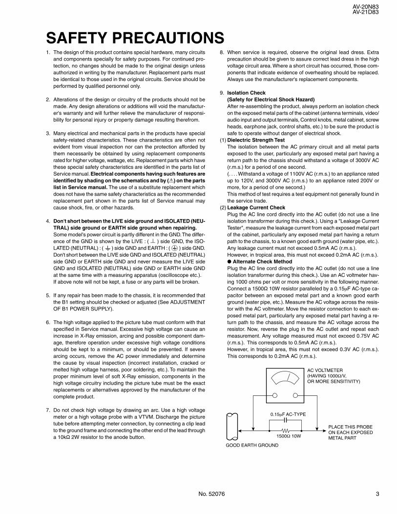
(2) Leakage Current CheckPlug the AC line cord directly into the AC outlet (do not use a lineisolation transformer during this check.). Using a "Leakage CurrentTester", measure the leakage current from each exposed metal partof the cabinet, particularly any exposed metal part having a returnpath to the chassis, to a known good earth ground (water pipe, etc.).Any leakage current must not exceed 0.5mA AC (r.m.s.).However, in tropical area, this must not exceed 0.2mA AC (r.m.s.). Alternate Check MethodPlug the AC line cord directly into the AC outlet (do not use a lineisolation transformer during this check.). Use an AC voltmeter hav-ing 1000 ohms per volt or more sensitivity in the following manner.Connect a 1500Ø 10W resistor paralleled by a 0.15µF AC-type ca-pacitor between an exposed metal part and a known good earthground (water pipe, etc.). Measure the AC voltage across the resis-tor with the AC voltmeter. Move the resistor connection to each ex-posed metal part, particularly any exposed metal part having a re-turn path to the chassis, and measure the AC voltage across theresistor. Now, reverse the plug in the AC outlet and repeat eachmeasurement. Any voltage measured must not exceed 0.75V AC(r.m.s.). This corresponds to 0.5mA AC (r.m.s.).However, in tropical area, this must not exceed 0.3V AC (r.m.s.).This corresponds to 0.2mA AC (r.m.s.).
AC VOLTMETER(HAVING 1000Ω/V,OR MORE SENSITIVITY)
PLACE THIS PROBEON EACH EXPOSEDMETAL PART1500Ω 10W
0.15µF AC-TYPE
GOOD EARTH GROUND
4 No. 52076
AV-20N83AV-21D83
FEATURESs New chassis design enables use of an interactive on-screen control.s Pure flat CRT produces fine textured picture in every detail.s Wide range voltage (110V ~ 240V) for AC power input.s With AUDIO/VIDEO/COMPONENT input terminals.s I 2 C bus control utilizes single chip ICs.s By means of AUTO PROGRAM, the TV stations can be selected
automatically and the TV channels can also be rearranged auto-matically.
s Built-in DIGITAL ECO MODE (ECONOMY, ECOLOGY).In accordance with the brightness in a room, the brightness and/orcontrast of the picture can be adjusted automatically to make theoptimum picture which is easy on the eye.
s Built-in OFF TIMER & RETURN +.
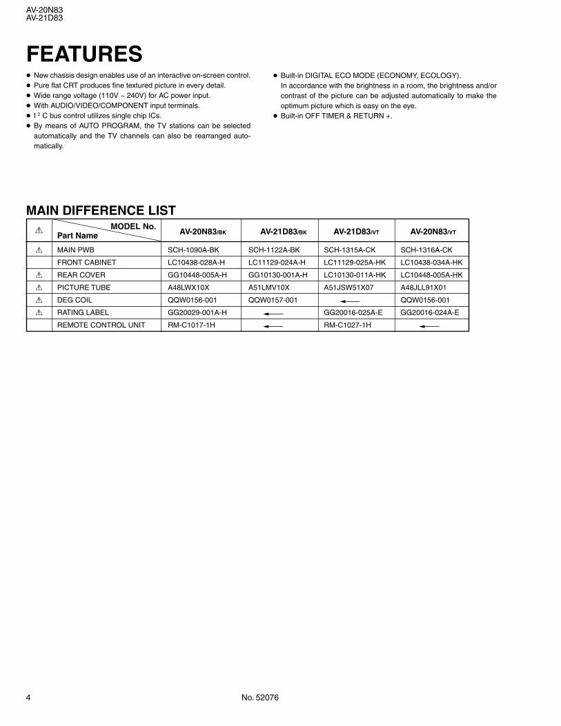
MAIN DIFFERENCE LIST!
MODEL No.AV-20N83/BK AV-21D83/BK AV-21D83/VT AV-20N83/VTPart Name
! MAIN PWB SCH-1090A-BK SCH-1122A-BK SCH-1315A-CK SCH-1316A-CK
FRONT CABINET LC10438-028A-H LC11129-024A-H LC11129-025A-HK LC10438-034A-HK
! REAR COVER GG10448-005A-H GG10130-001A-H LC10130-011A-HK LC10448-005A-HK
! PICTURE TUBE A48LWX10X A51LMV10X A51JSW51X07 A48JLL91X01
! DEG COIL QQW0156-001 QQW0157-001 QQW0156-001
! RATING LABEL GG20029-001A-H GG20016-025A-E GG20016-024A-E
REMOTE CONTROL UNIT RM-C1017-1H RM-C1027-1H
No. 52076 5
AV-20N83AV-21D83
FUNCTIONS
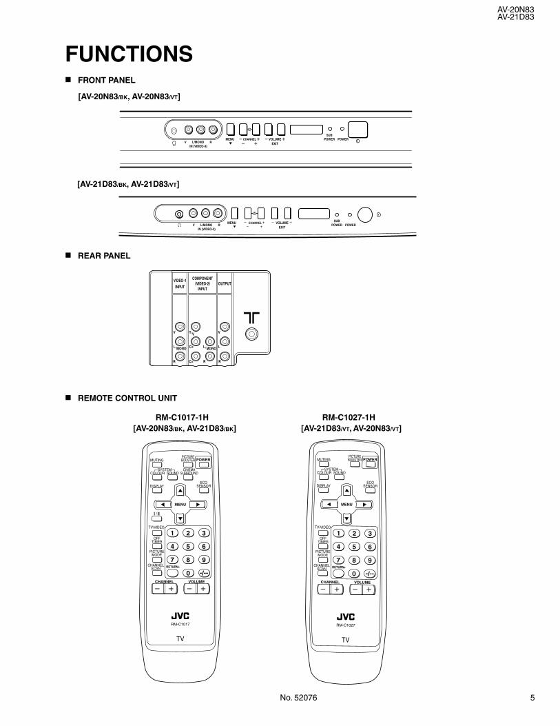
a REAR PANEL
a FRONT PANEL
a REMOTE CONTROL UNIT
MENU CHANNEL VOLUME POWERSUB
POWER
POWERSUB
POWER
EXITV RL/MONOIN (VIDEO-3)
V RL/MONOIN (VIDEO-3)
MENU CHANNEL VOLUMEEXIT
VIDEO-1
INPUTOUTPUT
COMPONENT(VIDEO-2)
INPUT
V
MONOL/
VY/ V
LMONOL/CB
R R RCR
[AV-21D83/BK, AV-21D83/VT]
[AV-20N83/BK, AV-20N83/VT]
MUTINGPICTUREBOOSTER
OFFTIMER
ECOSENSOR
PICTUREMODE
CHANNELSCAN
SYSTEMCOLOUR SOUND
MENU
CHANNEL
RETURN+
POWER
DISPLAY
TV/VIDEO
VOLUME
1 2 3
4 5 6
7 8 9
0 -/--
CINEMASURROUND
/
TV
RM-C1017
MUTINGPICTUREBOOSTER
OFFTIMER
ECOSENSOR
PICTUREMODE
CHANNELSCAN
SYSTEMCOLOUR SOUND
MENU
CHANNEL
RETURN+
POWER
DISPLAY
TV/VIDEO
VOLUME
1 2 3
4 5 6
7 8 9
0 -/--
TV
RM-C1027
1 2
[AV-20N83/BK, AV-21D83/BK]RM-C1017-1H
[AV-21D83/VT, AV-20N83/VT]RM-C1027-1H
6 No. 52076
AV-20N83
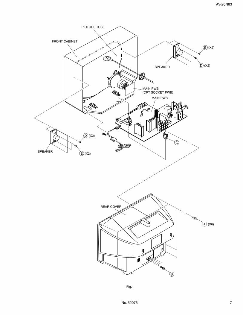
REMOVING THE REAR COVER1. Unplug the power supply cord.2. Remove the 6 screws marked Å and 4 screws marked ı as shown
in Fig.1.3. Withdraw the Rear cover toward you.
[CAUTION]
• When reinstalling the rear cover, carefully push it inward after in-serting the Main PWB into the rear cover groove.
REMOVING THE MAIN PW BOARD
• After removing the rear cover.1. Slightly raise the both sides of the Main PWB by hand, take off the
PB Stopper marked Ç from the front cabinet.2. Withdraw the Main PWB backward.
(If necessary, take off the wire clamp and connectors, etc.)
REMOVING THE SPEAKER [AV-20N83/BK]• After removing the rear cover.1. Remove the 2 screws marked Î and 2 screws marked as shown
in Fig.1.2. Follow the same steps when removing the other hand speaker.
REMOVING THE SPEAKER [AV-20N83/VT]• After removing the rear cover.1. Remove the 2 screws marked Î as shown in Fig.1.2. Follow the same steps when removing the other hand speaker.
CHECKING THE MAIN PW BOARD1. To check the back side of the Main PWB.
1) Pull out the Main PWB. (Refer to REMOVING THE MAIN PWBOARD).
2) Erect the Main PWB vertically so that you can easily check itsback side.
[CAUTION]
• Before turning on power, make sure that the CRT earth wire andother connectors are properly connected.
• When repairing, connect the Deg. coil to the DEG. connector on theMain PWB.
WIRE CLAMPING AND CABLE TYING1. Be sure to clamp the wire.2. Never remove the cable tie used for tying the wires together.
Should it be inadvertently removed, be sure to tie the wires with anew cable tie.
SPECIFIC SERVICE INSTRUCTIONSDISASSEMBLY PROCEDURE [AV-20N83/BK, AV-20N83/VT]
No. 52076 7
AV-20N83
Fig.1
A
B
(X6)
(X2)E
(X2)D
FRONT CABINET
PICTURE TUBE
MAIN PWB(CRT SOCKET PWB)
MAIN PWB
REAR COVER
SPEAKER
SPEAKER
C
(X2)D
(X2)E
8 No. 52076
AV-21D83
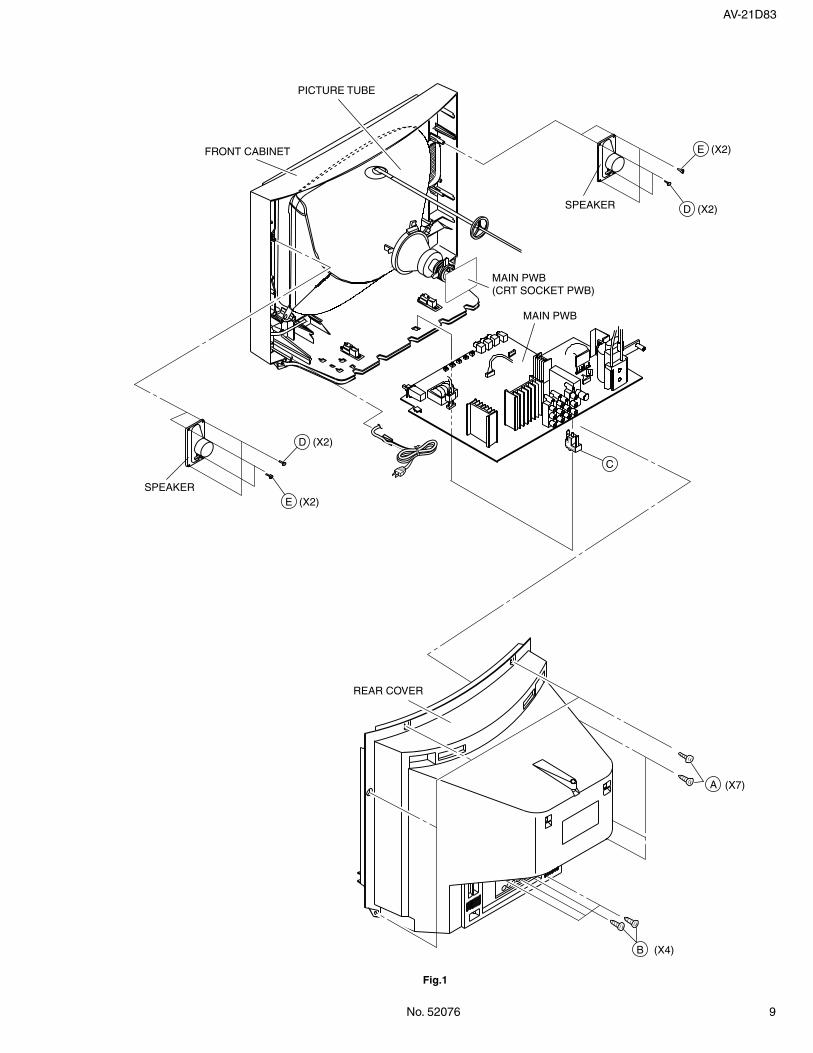
REMOVING THE REAR COVER1. Unplug the power supply cord.2. Remove the 7 screws marked Å and 4 screws marked ı as shown
in Fig.1.3. Withdraw the Rear cover toward you.
[CAUTION]
• When reinstalling the rear cover, carefully push it inward after in-serting the Main PWB into the rear cover groove.
REMOVING THE MAIN PW BOARD
• After removing the rear cover.1. Slightly raise the both sides of the Main PWB by hand, take off the
PB Stopper marked Ç from the front cabinet.2. Withdraw the Main PWB backward.
(If necessary, take off the wire clamp and connectors, etc.)
REMOVING THE SPEAKER [AV-21D83/BK]• After removing the rear cover.1. Remove the 2 screws marked Î as shown in Fig.1.2. Follow the same steps when removing the other hand speaker.
REMOVING THE SPEAKER [AV-21D83/VT]• After removing the rear cover.1. Remove the 2 screws marked Î and 2 screws marked as shown
in Fig.1.2. Follow the same steps when removing the other hand speaker.
CHECKING THE MAIN PW BOARD1. To check the back side of the Main PWB.
1) Pull out the Main PWB. (Refer to REMOVING THE MAIN PWBOARD).
2) Erect the Main PWB vertically so that you can easily check itsback side.
[CAUTION]
• Before turning on power, make sure that the CRT earth wire andother connectors are properly connected.
• When repairing, connect the Deg. coil to the DEG. connector on theMain PWB.
WIRE CLAMPING AND CABLE TYING1. Be sure to clamp the wire.2. Never remove the cable tie used for tying the wires together.
Should it be inadvertently removed, be sure to tie the wires with anew cable tie.
DISASSEMBLY PROCEDURE [AV-21D83/BK, AV-21D83/VT]
No. 52076 9
AV-21D83
Fig.1
FRONT CABINET
PICTURE TUBE
MAIN PWB(CRT SOCKET PWB)
MAIN PWB
SPEAKER
SPEAKER
REAR COVER
C
(X2)D
(X2)E
B (X4)
A (X7)
(X2)E
(X2)D
10 No. 52076
AV-20N83AV-21D83
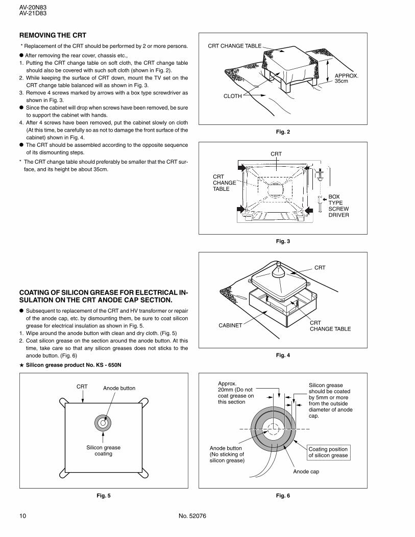
REMOVING THE CRT
* Replacement of the CRT should be performed by 2 or more persons.
• After removing the rear cover, chassis etc.,1. Putting the CRT change table on soft cloth, the CRT change table
should also be covered with such soft cloth (shown in Fig. 2).2. While keeping the surface of CRT down, mount the TV set on the
CRT change table balanced will as shown in Fig. 3.3. Remove 4 screws marked by arrows with a box type screwdriver as
shown in Fig. 3.
• Since the cabinet will drop when screws have been removed, be sureto support the cabinet with hands.
4. After 4 screws have been removed, put the cabinet slowly on cloth(At this time, be carefully so as not to damage the front surface of thecabinet) shown in Fig. 4.
• The CRT should be assembled according to the opposite sequenceof its dismounting steps.
* The CRT change table should preferably be smaller that the CRT sur-face, and its height be about 35cm.
COATING OF SILICON GREASE FOR ELECTRICAL IN-SULATION ON THE CRT ANODE CAP SECTION.
• Subsequent to replacement of the CRT and HV transformer or repairof the anode cap, etc. by dismounting them, be sure to coat silicongrease for electrical insulation as shown in Fig. 5.
1. Wipe around the anode button with clean and dry cloth. (Fig. 5)2. Coat silicon grease on the section around the anode button. At this
time, take care so that any silicon greases does not sticks to theanode button. (Fig. 6)
Silicon grease product No. KS - 650N
Fig. 2
CRT CHANGE TABLE
APPROX.35cm
CLOTH
Fig. 3
CRT
BOXTYPESCREWDRIVER
CRTCHANGETABLE
Fig. 4
CRTCHANGE TABLE
CRT
CABINET
Fig. 5
Anode buttonCRT
Silicon greasecoating
Fig. 6
Silicon grease should be coated by 5mm or more from the outside diameter of anode cap.
Approx.20mm (Do notcoat grease onthis section
Anode button(No sticking ofsilicon grease)
Anode cap
Coating positionof silicon grease
No. 52076 11
AV-20N83AV-21D83
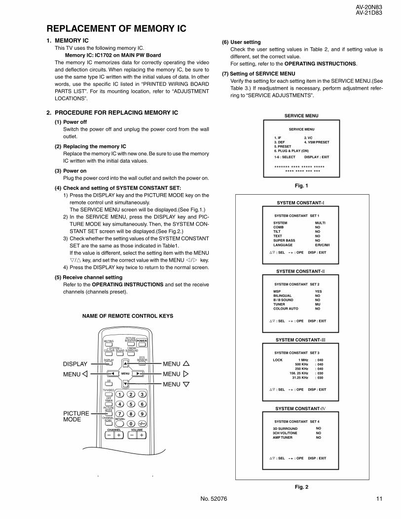
REPLACEMENT OF MEMORY IC1. MEMORY IC
This TV uses the following memory IC.Memory IC: IC1702 on MAIN PW Board
The memory IC memorizes data for correctly operating the videoand deflection circuits. When replacing the memory IC, be sure touse the same type IC written with the initial values of data. In otherwords, use the specific IC listed in “PRINTED WIRING BOARDPARTS LIST”. For its mounting location, refer to “ADJUSTMENTLOCATIONS”.
2. PROCEDURE FOR REPLACING MEMORY IC
(1) Power offSwitch the power off and unplug the power cord from the walloutlet.
(2) Replacing the memory ICReplace the memory IC with new one. Be sure to use the memoryIC written with the initial data values.
(3) Power onPlug the power cord into the wall outlet and switch the power on.
(4) Check and setting of SYSTEM CONSTANT SET:1) Press the DISPLAY key and the PICTURE MODE key on the
remote control unit simultaneously.The SERVICE MENU screen will be displayed.(See Fig.1.)
2) In the SERVICE MENU, press the DISPLAY key and PIC-TURE MODE key simultaneously. Then, the SYSTEM CON-STANT SET screen will be displayed.(See Fig.2.)
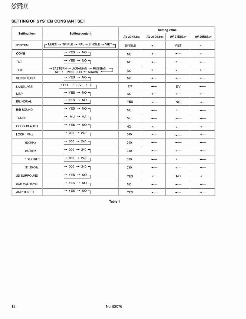
3) Check whether the setting values of the SYSTEM CONSTANTSET are the same as those indicated in Table1.If the value is different, select the setting item with the MENU&/^ key, and set the correct value with the MENU */T key.
4) Press the DISPLAY key twice to return to the normal screen.
(5) Receive channel settingRefer to the OPERATING INSTRUCTIONS and set the receivechannels (channels preset).
NAME OF REMOTE CONTROL KEYS
Fig. 1
Fig. 2
DISPLAY
MENU
PICTUREMODE
MUTING
OFFTIMER
ECOSENSOR
PICTUREMODE
CHANNELSCAN
REVEAL
SUBPAGE CANCEL
TV
TEXT
HOLD
RM-C1010
INDEX
STORE MODE
SIZE
SYSTEMCOLOUR SOUND
MENU
CHANNEL
RETURN+
POWER
DISPLAY
TV/TEXT
TV/VIDEO
VOLUME
1 2 3
4 5 6
7 8 9
0 -/--
CINEMASURROUND
PICTUREBOOSTER
I/II
MENU
MENU
MENU
SYSTEM CONSTANT-Ι
>? : SEL - + : OPE
COMBTILT
MULTI
NONO
TEXT NOSUPER BASS NOLANGUAGE E/R/C/M/I
SYSTEM CONSTANT SET 1
SYSTEM
DISP : EXIT
SYSTEM CONSTANT-II
>? : SEL - + : OPE
B / B SOUND
YES
NOTUNER MUCOLOUR AUTO NO
BILINGUAL NO
SYSTEM CONSTANT SET 2
MSP
DISP : EXIT
SYSTEM CONSTANT-III
>? : SEL - + : OPE
: 040: 040
SYSTEM CONSTANT SET 3
LOCK 1 MHz500 KHz
: 040250 KHz: 030156. 25 KHz: 03031.25 KHz
DISP : EXIT
SYSTEM CONSTANT-IV
>? : SEL - + : OPE
NONO
SYSTEM CONSTANT SET 4
3D SURROUND
NO3CH VOL/TONEAMP TUNER
DISP : EXIT
SERVICE MENU
1. IF3. DEF5. PRESET6. PLUG & PLAY (ON)
2. VC4. VSM PRESET
SERVICE MENU
1-6 : SELECT DISPLAY : EXIT
******* **** ***** ***** **** **** *** ***
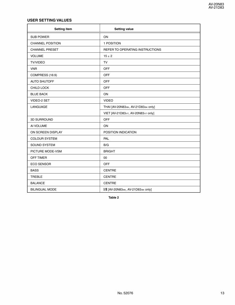
(6) User settingCheck the user setting values in Table 2, and if setting value isdifferent, set the correct value.For setting, refer to the OPERATING INSTRUCTIONS.
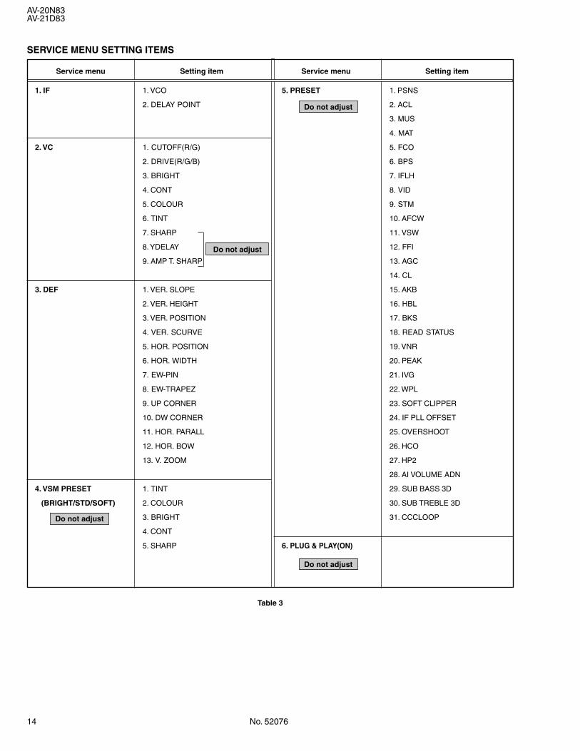
(7) Setting of SERVICE MENUVerify the setting for each setting item in the SERVICE MENU.(SeeTable 3.) If readjustment is necessary, perform adjustment refer-ring to “SERVICE ADJUSTMENTS”.
12 No. 52076
AV-20N83AV-21D83
Setting item Setting contentSetting value
YES NO
MULTI TRIPLE PAL SINGLE VIET
YES NO
YES NO
000 240
000 240
000 240
000 240
YES NO
YES NO
YES NO
YES NO
MU MA
YES NO
YES NO
YES NO
AV-21D83/BKAV-20N83/BK
SYSTEM
COMB
TILT
TEXT
SUPER BASS
LANGUAGE
MSP
BILINGUAL
B/B SOUND
TUNER
COLOUR AUTO
LOCK 1MHz
500KHz
250KHz
156.25KHz
31.25KHz
3D SURROUND
3CH VOL/TONE
AMP TUNER
SINGLE VIET
MU
NO
040
040
000 240 040
030
030
NO
NO
NO
E/ T E/V E E/T
NO
NOYES
YES
E/V
NO
YES
AV-21D83/VT AV-20N83/VT
NO
NO
NO
EASTERN UKRANIAN RUSSIAN NO PAN EURO ARABK
SETTING OF SYSTEM CONSTANT SET
Table 1
No. 52076 13
AV-20N83AV-21D83
Setting item Setting value
SUB POWER ON
CHANNEL POSITION 1 POSITION
CHANNEL PRESET REFER TO OPERATING INSTRUCTIONS
VOLUME 15 ± 2
TV/VIDEO TV
VNR OFF
COMPRESS (16:9) OFF
AUTO SHUTOFF OFF
CHILD LOCK OFF
BLUE BACK ON
VIDEO-2 SET VIDEO
LANGUAGE THAI [AV-20N83/BK, AV-21D83/BK only]
VIET [AV-21D83/VT, AV-20N83/VT only]
3D SURROUND OFF
AI VOLUME ON
ON SCREEN DISPLAY POSITION INDICATION
COLOUR SYSTEM PAL
SOUND SYSTEM B/G
PICTURE MODE-VSM BRIGHT
OFF TIMER 00
ECO SENSOR OFF
BASS CENTRE
TREBLE CENTRE
BALANCE CENTRE
BILINGUAL MODE 1/2 [AV-20N83/BK, AV-21D83/BK only]
USER SETTING VALUES
Table 2
14 No. 52076
AV-20N83AV-21D83
1. IF 1. VCO
2. DELAY POINT
2. VC 1. CUTOFF(R/G)
2. DRIVE(R/G/B)
3. BRIGHT
4. CONT
5. COLOUR
6. TINT
7. SHARP
8. YDELAY
9. AMP T. SHARP
3. DEF 1. VER. SLOPE
2. VER. HEIGHT
3. VER. POSITION
4. VER. SCURVE
5. HOR. POSITION
6. HOR. WIDTH
7. EW-PIN
8. EW-TRAPEZ
9. UP CORNER
10. DW CORNER
11. HOR. PARALL
12. HOR. BOW
13. V. ZOOM
4. VSM PRESET 1. TINT
(BRIGHT/STD/SOFT) 2. COLOUR
3. BRIGHT
4. CONT
5. SHARP
Service menu Setting item
SERVICE MENU SETTING ITEMS
Service menu Setting item
5. PRESET 1. PSNS
2. ACL
3. MUS
4. MAT
5. FCO
6. BPS
7. IFLH
8. VID
9. STM
10. AFCW
11. VSW
12. FFI
13. AGC
14. CL
15. AKB
16. HBL
17. BKS
18. READ STATUS
19. VNR
20. PEAK
21. IVG
22. WPL
23. SOFT CLIPPER
24. IF PLL OFFSET
25. OVERSHOOT
26. HCO
27. HP2
28. AI VOLUME ADN
29. SUB BASS 3D
30. SUB TREBLE 3D
31. CCCLOOP
6. PLUG & PLAY(ON)
Do not adjust
Do not adjust
Do not adjust
Do not adjust
Table 3
No. 52076 15
AV-20N83AV-21D83
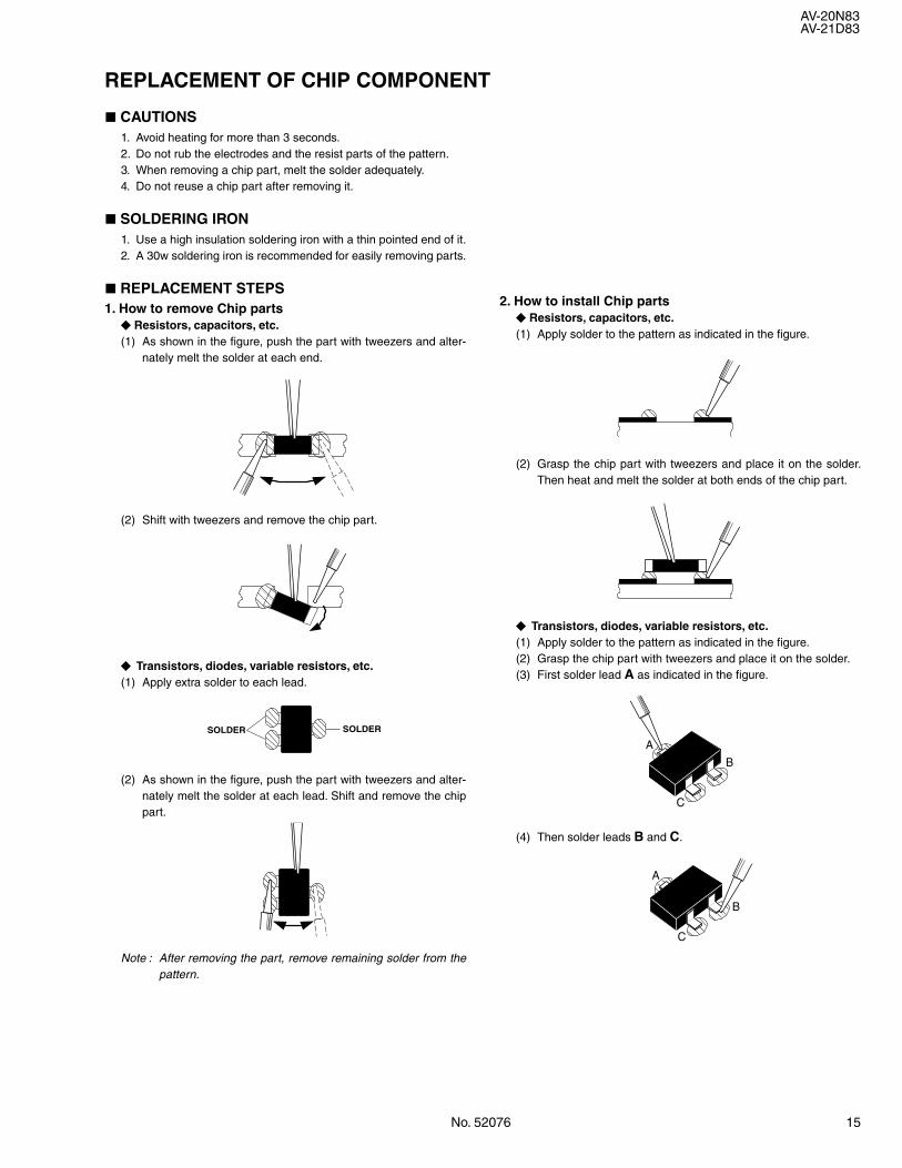
a CAUTIONS1. Avoid heating for more than 3 seconds.2. Do not rub the electrodes and the resist parts of the pattern.3. When removing a chip part, melt the solder adequately.4. Do not reuse a chip part after removing it.
a SOLDERING IRON1. Use a high insulation soldering iron with a thin pointed end of it.2. A 30w soldering iron is recommended for easily removing parts.
a REPLACEMENT STEPS1. How to remove Chip parts
Resistors, capacitors, etc.(1) As shown in the figure, push the part with tweezers and alter-
nately melt the solder at each end.
(2) Shift with tweezers and remove the chip part.
Transistors, diodes, variable resistors, etc.(1) Apply extra solder to each lead.
(2) As shown in the figure, push the part with tweezers and alter-nately melt the solder at each lead. Shift and remove the chippart.
Note : After removing the part, remove remaining solder from thepattern.
REPLACEMENT OF CHIP COMPONENT
2. How to install Chip parts Resistors, capacitors, etc.
(1) Apply solder to the pattern as indicated in the figure.
(2) Grasp the chip part with tweezers and place it on the solder.Then heat and melt the solder at both ends of the chip part.
Transistors, diodes, variable resistors, etc.(1) Apply solder to the pattern as indicated in the figure.(2) Grasp the chip part with tweezers and place it on the solder.(3) First solder lead A as indicated in the figure.
(4) Then solder leads B and C.
SOLDER SOLDER
A
B
C
A
B
C
16 No. 52076
AV-20N83AV-21D83
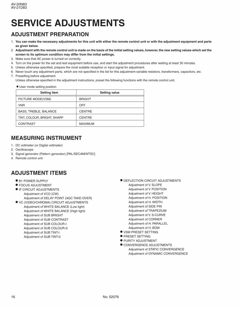
SERVICE ADJUSTMENTSADJUSTMENT PREPARATION1. You can make the necessary adjustments for this unit with either the remote control unit or with the adjustment equipment and parts
as given below.2. Adjustment with the remote control unit is made on the basis of the initial setting values, however, the new setting values which set the
screen to its optimum condition may differ from the initial settings.3. Make sure that AC power is turned on correctly.4. Turn on the power for the set and test equipment before use, and start the adjustment procedures after waiting at least 30 minutes.5. Unless otherwise specified, prepare the most suitable reception or input signal for adjustment.6. Never touch any adjustment parts, which are not specified in the list for this adjustment-variable resistors, transformers, capacitors, etc.7. Presetting before adjustment.
Unless otherwise specified in the adjustment instructions, preset the following functions with the remote control unit.
Setting item Setting value
PICTURE MODE(VSM) BRIGHT
VNR OFF
BASS, TREBLE, BALANCE CENTRE
TINT, COLOUR, BRIGHT, SHARP CENTRE
CONTRAST MAXIMUM
MEASURING INSTRUMENT1. DC voltmeter (or Digital voltmeter)2. Oscilloscope3. Signal generator (Pattern generator) [PAL/SECAM/NTSC]4. Remote control unit
ADJUSTMENT ITEMS• B1 POWER SUPPLY
• FOCUS ADJUSTMENT
• IF CIRCUIT ADJUSTMENTSAdjustment of VCO (CW)Adjustment of DELAY POINT (AGC TAKE-OVER)
• VC (VIDEO/CHROMA) CIRCUIT ADJUSTMENTSAdjustment of WHITE BALANCE (Low light)Adjustment of WHITE BALANCE (High light)Adjustment of SUB BRIGHTAdjustment of SUB CONTRASTAdjustment of SUB COLOUR-ΙAdjustment of SUB COLOUR-ΙΙAdjustment of SUB TINT-ΙAdjustment of SUB TINT-ΙΙ
• User mode setting position
• DEFLECTION CIRCUIT ADJUSTMENTSAdjustment of V. SLOPEAdjustment of V. POSITIONAdjustment of V. HEIGHTAdjustment of H. POSITIONAdjustment of H. WIDTHAdjustment of SIDE PINAdjustment of TRAPEZIUMAdjustment of V. S-CURVEAdjustment of CORNERAdjustment of H. PARALLELAdjustment of H. BOW
• VSM PRESET SETTING
• PRESET SETTING
• PURITY ADJUSTMENT
• CONVERGENCE ADJUSTMENTSAdjustment of STATIC CONVERGENCEAdjustment of DYNAMIC CONVERGENCE
No. 52076 17
AV-20N83AV-21D83
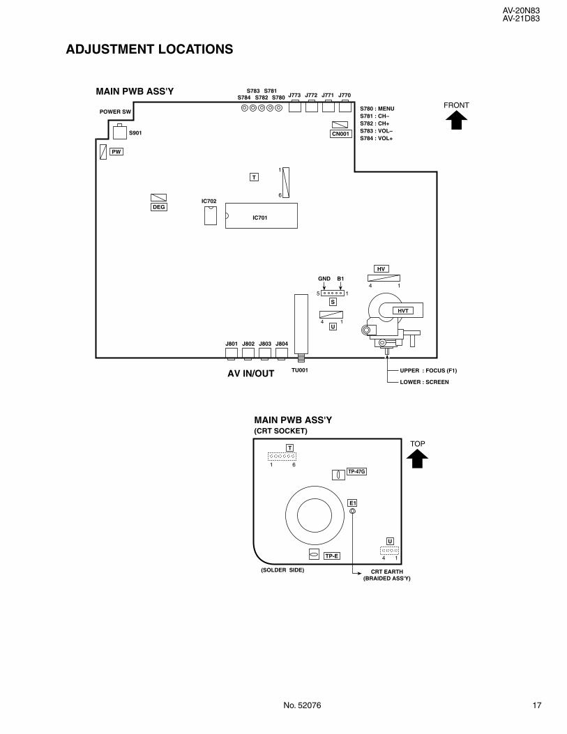
ADJUSTMENT LOCATIONS
E1
TOP
CRT EARTH(SOLDER SIDE)
(BRAIDED ASS'Y)
U
TP-47G
HV
4 1
GND B1
UPPER : FOCUS (F1)
IC702
MAIN PWB ASS'Y(CRT SOCKET)
T
61
4 1
FRONT
AV IN/OUT
HVT
MAIN PWB ASS'Y
1
6
1
145
S
U
LOWER : SCREEN
TU001
J770
S901
J773S784 S782 S780S783 S781
J772 J771
J804J801 J802 J803
IC701
CN001
T
PW
DEG
TP-E
S780 : MENUS781 : CH–S782 : CH+S783 : VOL–S784 : VOL+
POWER SW
18 No. 52076
AV-20N83AV-21D83
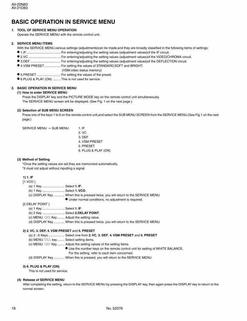
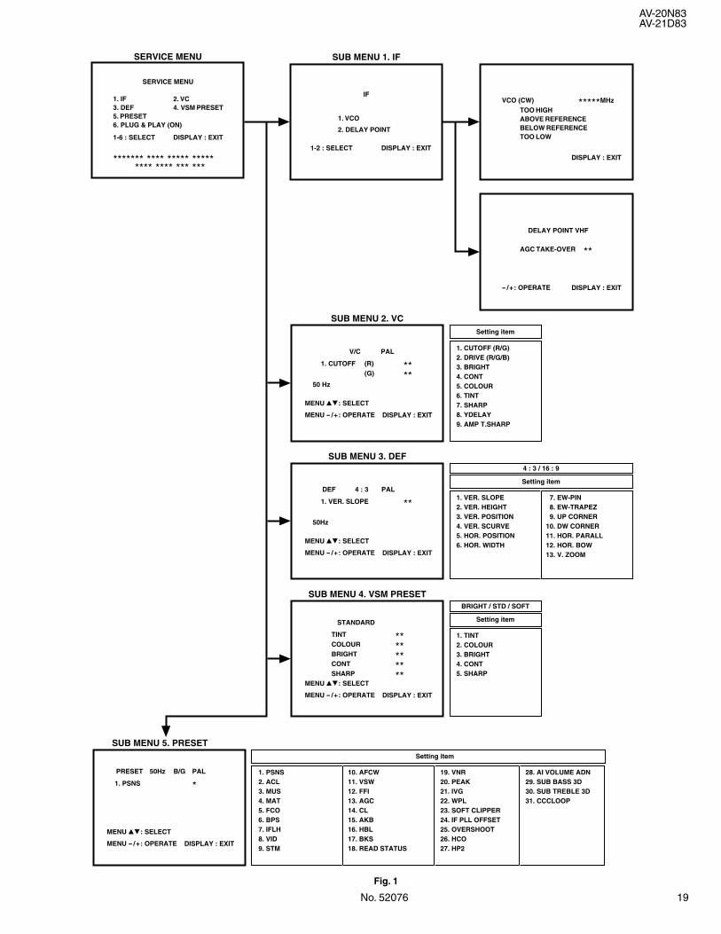
BASIC OPERATION IN SERVICE MENU1. TOOL OF SERVICE MENU OPERATION
Operate the SERVICE MENU with the remote control unit.
2. SERVICE MENU ITEMSWith the SERVICE MENU,various settings (adjustments)can be made,and they are broadly classified in the following items of settings:
• 1.IF ......................................For entering/adjusting the setting values (adjustment values)of the IF circuit.
• 2.VC ....................................For entering/adjusting the setting values (adjustment values)of the VIDEO/CHROMA circuit.
• 3.DEF ..................................For entering/adjusting the setting values (adjustment values)of the DEFLECTION circuit.
• 4.VSM PRESET .................. For setting the values of STANDARD,SOFT and BRIGHT.(VSM:video status memory)
• 5.PRESET ...........................For setting the values of the preset.
• 6.PLUG & PLAY (ON) .........This is not used for service.
3. BASIC OPERATION IN SERVICE MENU(1) How to enter SERVICE MENU
Press the DISPLAY key and the PICTURE MODE key on the remote control unit simultaneously.The SERVICE MENU screen will be displayed. (See Fig. 1 on the next page.)
(2) Selection of SUB MENU SCREENPress one of the keys 1 to 6 on the remote control unit,and select the SUB MENU SCREEN from the SERVICE MENU.(See Fig.1 on the nextpage.)
SERVICE MENU → SUB MENU 1. IF2. VC3. DEF4. VSM PRESET5. PRESET6. PLUG & PLAY (ON)
(3) Method of Setting*Once the setting values are set,they are memorized automatically.*It must not adjust without inputting a signal.
1) 1. IF[1.VCO ]
(a) 1 Key ......................... Select 1. IF.(b) 1 Key ......................... Select 1. VCO.(c) DISPLAY Key ............ When this is pressed twice, you will return to the SERVICE MENU.
• Under normal conditions, no adjustment is required.[2.DELAY POINT ]
(a) 1 Key ......................... Select 1. IF.(b) 2 Key ......................... Select 2.DELAY POINT.(c) MENU */TKey ........ Adjust the setting value.(d) DISPLAY Key ............ When this is pressed twice, you will return to the SERVICE MENU.
2) 2. VC, 3. DEF, 4. VSM PRESET and 5. PRESET(a) 2 ~5 Keys .................. Select one from 2. VC, 3. DEF, 4. VSM PRESET and 5. PRESET(b) MENU &/^ key ........ Select setting items.(c) MENU */TKey ........ Adjust the setting values of the setting items.
• Use the number keys on the remote control unit for setting of WHITE BALANCE.For the setting, refer to each item concerned.
(d) DISPLAY Key ............ When this is pressed, you will return to the SERVICE MENU.
3) 6. PLUG & PLAY (ON)This is not used for service.
(4) Release of SERVICE MENUAfter completing the setting, return to the SERVICE MENU by pressing the DISPLAY key, then again press the DISPLAY key to return to thenormal screen.
No. 52076 19
AV-20N83AV-21D83
Fig. 1
1-2 : SELECT DISPLAY : EXIT
SUB MENU 1. IFSERVICE MENU
1. VCO
2. DELAY POINT
IFVCO (CW) *****MHz
DISPLAY : EXIT
TOO HIGHABOVE REFERENCEBELOW REFERENCETOO LOW
DELAY POINT VHF
AGC TAKE-OVER **
- /+: OPERATE DISPLAY : EXIT
SUB MENU 2. VC
50 Hz
Setting item
1. CUTOFF (R/G) 2. DRIVE (R/G/B) 3. BRIGHT 4. CONT 5. COLOUR 6. TINT 7. SHARP 8. YDELAY 9. AMP T.SHARP
4 : 3 / 16 : 9
1. VER. SLOPE 2. VER. HEIGHT 3. VER. POSITION 4. VER. SCURVE 5. HOR. POSITION 6. HOR. WIDTH
Setting item
7. EW-PIN 8. EW-TRAPEZ 9. UP CORNER10. DW CORNER11. HOR. PARALL12. HOR. BOW13. V. ZOOM
MENU 89: SELECT
MENU - /+: OPERATE DISPLAY : EXIT
SUB MENU 3. DEF
50Hz
PAL
1. CUTOFF (R)(G)
****
V/C
PAL
1. VER. SLOPE **DEF 4 : 3
MENU 89: SELECT
MENU - /+: OPERATE DISPLAY : EXIT
SUB MENU 5. PRESET
PALB/G
1. PSNS *PRESET 50Hz
MENU 89: SELECT
MENU - /+: OPERATE DISPLAY : EXIT
SUB MENU 4. VSM PRESET
TINT **COLOUR **BRIGHT **CONT **SHARP **
STANDARD
MENU 89: SELECT
MENU - /+: OPERATE DISPLAY : EXIT
1. PSNS 2. ACL 3. MUS 4. MAT 5. FCO 6. BPS 7. IFLH 8. VID 9. STM
Setting item
10. AFCW11. VSW12. FFI13. AGC14. CL15. AKB16. HBL17. BKS18. READ STATUS
19. VNR20. PEAK21. IVG22. WPL23. SOFT CLIPPER24. IF PLL OFFSET25. OVERSHOOT26. HCO27. HP2
28. AI VOLUME ADN29. SUB BASS 3D30. SUB TREBLE 3D31. CCCLOOP
BRIGHT / STD / SOFT
1. TINT 2. COLOUR 3. BRIGHT 4. CONT 5. SHARP
Setting item
1. IF3. DEF5. PRESET6. PLUG & PLAY (ON)
2. VC4. VSM PRESET
SERVICE MENU
1-6 : SELECT DISPLAY : EXIT
******* **** ***** ***** **** **** *** ***
20 No. 52076
AV-20N83AV-21D83
ADJUSTMENTS
ItemMeasuringinstrument
Test point Adjustment part Description
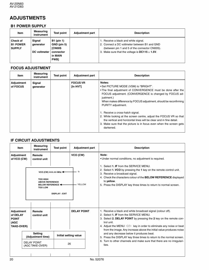
Check ofB1 POWERSUPPLY
Signalgenerator
DC voltmeter
B1 (pin 1)GND (pin 5)[CN00Sconnectorin MAINPWB]
1. Receive a black and white signal.2. Connect a DC voltmeter between B1 and GND
(between pin 1 and 5 of the connector CN00S).3. Make sure that the voltage is DC115 ± 1.5V.
Adjustmentof FOCUS
FOCUS VR[In HVT]
ItemMeasuringinstrument Test point Adjustment part Description
FOCUS ADJUSTMENT
B1 POWER SUPPLY
Signalgenerator
Notes:• Set PICTURE MODE (VSM) to “BRIGHT”.• The final adjustment of CONVERGENCE must be done after theFOCUS adjustment. (CONVERGENCE is changed by FOCUS ad-justment.)When makes difference by FOCUS adjustment, should be reconfirmingPURITY adjustment.
1. Receive a cross-hatch signal.2. While looking at the screen centre, adjust the FOCUS VR so that
the vertical and horizontal lines will be clear and in fine detail.3. Make sure that the picture is in focus even when the screen gets
darkened.
Adjustmentof VCO (CW)
VCO (CW)
ItemMeasuringinstrument Test point Adjustment part Description
IF CIRCUIT ADJUSTMENTS
Remotecontrol unit
Note:• Under normal conditions, no adjustment is required.
1. Select 1. IF from the SERVICE MENU.2. Select 1. VCO by pressing the 1 key on the remote control unit.3. Receive a broadcast signal.4. Check the characters colour of the BELOW REFERENCE displayed
to yellow.5. Press the DISPLAY key three times to return to normal screen.
TOO HIGHABOVE REFERENCEBELOW REFERENCETOO LOW
VCO (CW) . MHz
DISPLAY : EXIT
fv
YELLOW
Adjustmentof DELAYPOINT(AGCTAKE-OVER)
DELAY POINTRemotecontrol unit
1. Receive a black and white broadcast signal (colour off).2. Select 1. IF from the SERVICE MENU.3. Select 2. DELAY POINT by pressing the 2 key on the remote con-
trol unit.4. Adjust the MENU */T key in order to eliminate any noise or beat
from the image. Any increase above the initial value produces noiseand any decrease below it produces beat.
5. Press the DISPLAY key three times to return to the normal screen.6. Turn to other channels and make sure that there are no irregulari-
ties.
SettingInitial setting value(Adjustment time)
DELAY POINT 26(AGC TAKE-OVER)
No. 52076 21
AV-20N83AV-21D83
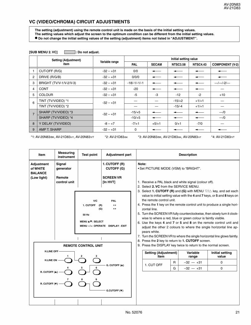
VC (VIDEO/CHROMA) CIRCUIT ADJUSTMENTS
The setting (adjustment) using the remote control unit is made on the basis of the initial setting values.The setting values which adjust the screen to the optimum condition can be different from the initial setting values.
• Do not change the initial setting values of the setting (adjustment) items not listed in “ADJUSTMENT”.
[SUB MENU 2. VC] : Do not adjust.
Setting (Adjustment) Variable rangeInitial setting value
item PAL SECAM NTSC3.58 NTSC4.43 COMPONENT (V-2)
ItemMeasuringinstrument
Test point Adjustment part Description
Adjustmentof WHITEBALANCE(Low light)
1.CUTOFF (R)CUTOFF (G)
SCREEN VR[In HVT]
Note:• Set PICTURE MODE (VSM) to “BRIGHT”.
1. Receive a PAL black and white signal (colour off).2. Select 2. VC from the SERVICE MENU.3. Select 1. CUTOFF (R) and (G) with MENU &/^ key, and set each
value to initial setting value with the 4 and 7 keys, or 5 and 8 keys onthe remote control unit.
4. Press the 1 key on the remote control unit to produce a single hori-zontal line.
5. Turn the SCREEN VR fully counterclockwise, then slowly turn it clock-wise to where a red, blue or green colour is faintly visible.
6. Use the keys 4 and 7 or 5 and 8 on the remote control unit andadjust the other 2 colours to where the single horizontal line ap-pears white.
7. Turn the SCREEN VR to where the single horizontal line glows faintly.8. Press the 2 key to return to 1. CUTOFF screen.9. Press the DISPLAY key twice to return to the normal screen.
Setting (Adjustment) Variable Initial settingItem range value
1. CUT OFFR –32 — +31 0
G –32 — +31 0
PAL
1. CUTOFF
50 Hz
(R)(G)
****
V/C
MENU 89: SELECT
MENU - /+: OPERATE DISPLAY : EXIT
Signalgenerator
Remotecontrol unit
G. CUTOFF (8)
H.LINE OFF
H.LINE ON
1 2 3
4
7 8 9
5 6
R. CUTOFF (8)
R. CUTOFF (9)
G.CUTOFF (9)
REMOTE CONTROL UNIT
1 CUT-OFF (R/G) -32 – +31 0/0
2 DRIVE (R/G/B) -32 – +31 0/0/0
3 BRIGHT (TV/V-1/V-2/V-3) -32 – +31 -18/-1/-1/-1 —/—/-2/—
4 CONT -32 – +31 -20 —
5 COLOUR -32 – +31 -5 -3 -12 -2 +10
TINT (TV/VIDEO) *1 — — -15/+2 +1/+1 —6
TINT (TV/VIDEO) *2-32 – +31
— — -15/-4 +1/+1 —
SHARP (TV/VIDEO) *3 -15/+5 —/07
SHARP (TV/VIDEO) *4-32 – +31
-10/+5 —/0
8 Y DELAY (TV/VIDEO) -8 – +7 -7/+1 +5/+1 0/+1 -7/0 —
9 AMP T. SHARP -32 – +31 0
*1: AV-20N83/BK, AV-21D83/VT, AV-20N83/VT *2: AV-21D83/BK *3: AV-20N83/BK, AV-21D83/BK, AV-20N83/VT *4: AV-21D83/VT
22 No. 52076
AV-20N83AV-21D83
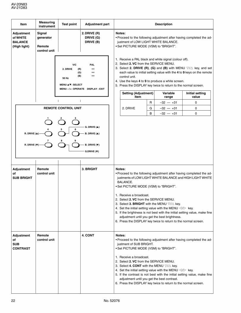
ItemMeasuringinstrument
Test point Adjustment part Description
AdjustmentofSUB BRIGHT
Remotecontrol unit
Notes:• Proceed to the following adjustment after having completed the ad-justments of LOW LIGHT WHITE BALANCE and HIGH LIGHT WHITEBALANCE.
• Set PICTURE MODE (VSM) to “BRIGHT”.
1. Receive a broadcast.2. Select 2. VC from the SERVICE MENU.3. Select 3. BRIGHT with the MENU &/^ key.4. Set the initial setting value with the MENU */T key.5. If the brightness is not best with the initial setting value, make fine
adjustment until you get the best brightness.6. Press the DISPLAY key twice to return to the normal screen.
3. BRIGHT
AdjustmentofSUBCONTRAST
Remotecontrol unit
Notes:• Proceed to the following adjustment after having completed the ad-justment of SUB BRIGHT.
• Set PICTURE MODE (VSM) to “BRIGHT”.
1. Receive a broadcast.2. Select 2. VC from the SERVICE MENU.3. Select 4. CONT with the MENU &/^ key.4. Set the initial setting value with the MENU */T key.5. If the contrast is not best with the initial setting value, make fine
adjustment until you get the best contrast.6. Press the DISPLAY key twice to return to the normal screen.
4. CONT
Adjustmentof WHITEBALANCE(High light)
Signalgenerator
Remotecontrol unit
2.DRIVE (R)DRIVE (G)DRIVE (B)
Notes:• Proceed to the following adjustment after having completed the ad-justment of LOW LIGHT WHITE BALANCE.
• Set PICTURE MODE (VSM) to “BRIGHT”.
1. Receive a PAL black and white signal (colour off).2. Select 2. VC from the SERVICE MENU.3. Select 2. DRIVE (R), (G) and (B) with MENU &/^ key, and set
each value to initial setting value with the 4 to 9 keys on the remotecontrol unit.
4. Use the keys 4 to 9 to produce a white screen.5. Press the DISPLAY key twice to return to the normal screen.
Setting (Adjustment) Variable Initial settingItem range value
R –32 — +31 0
2. DRIVE G –32 — +31 0
B –32 — +31 0
G. DRIVE (8)
1 2 3
4
7 8 9
5 6
R. DRIVE (8) B. DRIVE (8)
B. DRIVE (9)R. DRIVE (9)
G.DRIVE (9)
REMOTE CONTROL UNIT
PAL
2. DRIVE
50 Hz
(R)(G)
****
(B) **
V/C
MENU 89: SELECT
MENU - /+: OPERATE DISPLAY : EXIT
No. 52076 23
AV-20N83AV-21D83
ItemMeasuringinstrument
Test point Adjustment part Description
AdjustmentofSUBCOLOUR-I
Remotecontrol unit
[Method of adjustment without measuring instrument]
Notes:• Proceed to the following adjustment after having completed the ad-justment of SUB CONT.
• Set PICTURE MODE (VSM) to “BRIGHT”.
– PAL COLOUR –1. Receive a PAL broadcast.2. Select 2. VC from the SERVICE MENU.3. Select 5. COLOUR with the MENU &/^ key.4. Set the initial setting value for PAL COLOUR with the MENU */Tkey.5. If the colour is not best with the initial setting value, make fine ad-
justment until you get the best colour.6. Press the DISPLAY key twice to return to the normal screen.
– SECAM COLOUR –7. Receive a SECAM broadcast.8. Press the COLOUR SYSTEM button on the remote control unit to
select the SECAM colour system.9. Make fine adjustment of SECAM COLOUR in the same way as for
“PAL COLOUR”.
– NTSC 3.58 COLOUR –10. Receive a NTSC 3.58MHz broadcast.11. Press the COLOUR SYSTEM button on the remote control unit to
select the NTSC 3.58 colour system.12. Make similar fine adjustment of NTSC 3.58 COLOUR in the same
way as for “PAL COLOUR”.
– NTSC 4.43 COLOUR –When adjustment is done for NTSC 3.58 COLOUR, appropriatevalues are automatically set for NTSC 4.43 COLOUR.
5. COLOUR
AdjustmentofSUBCOLOUR-II
Signalgenerator
Oscilloscope
Remotecontrol unit
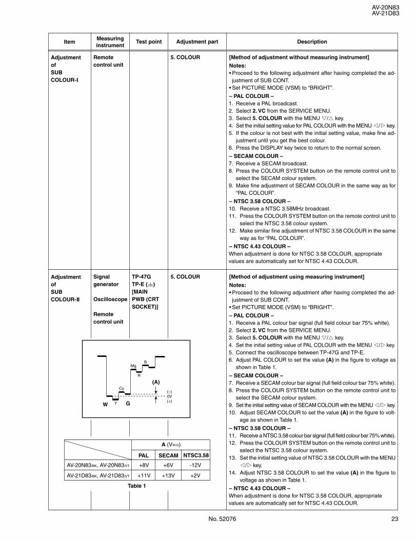
5. COLOUR [Method of adjustment using measuring instrument]
Notes:• Proceed to the following adjustment after having completed the ad-justment of SUB CONT.
• Set PICTURE MODE (VSM) to “BRIGHT”.
– PAL COLOUR –1. Receive a PAL colour bar signal (full field colour bar 75% white).2. Select 2. VC from the SERVICE MENU.3. Select 5. COLOUR with the MENU &/^ key.4. Set the initial setting value of PAL COLOUR with the MENU */Tkey.5. Connect the oscilloscope between TP-47G and TP-E.6. Adjust PAL COLOUR to set the value (A) in the figure to voltage as
shown in Table 1.
– SECAM COLOUR –7. Receive a SECAM colour bar signal (full field colour bar 75% white).8. Press the COLOUR SYSTEM button on the remote control unit to
select the SECAM colour system.9. Set the initial setting value of SECAM COLOUR with the MENU */Tkey.10. Adjust SECAM COLOUR to set the value (A) in the figure to volt-
age as shown in Table 1.
– NTSC 3.58 COLOUR –11. Receive a NTSC 3.58 colour bar signal (full field colour bar 75% white).12. Press the COLOUR SYSTEM button on the remote control unit to
select the NTSC 3.58 colour system.13. Set the initial setting value of NTSC 3.58 COLOUR with the MENU
*/Tkey.14. Adjust NTSC 3.58 COLOUR to set the value (A) in the figure to
voltage as shown in Table 1.
– NTSC 4.43 COLOUR –When adjustment is done for NTSC 3.58 COLOUR, appropriatevalues are automatically set for NTSC 4.43 COLOUR.
TP-47GTP-E (H)[MAINPWB (CRTSOCKET)]
MgB
(–)0V(+)
R
Cy
YW G
(A)
A (VW-G)
PAL SECAM NTSC3.58
AV-20N83/BK, AV-20N83/VT +8V +6V -12V
AV-21D83/BK, AV-21D83/VT +11V +13V +2V
Table 1
24 No. 52076
AV-20N83AV-21D83
ItemMeasuringinstrument
Test point Adjustment part Description
AdjustmentofSUB TINT-I
Signalgenerator
Remotecontrol unit
6. TINT [Method of adjustment without measuring instrument]
Notes:• Proceed to the following adjustment after having completed theadjustment of SUB CONT.
• Set PICTURE MODE (VSM) to “BRIGHT”.
– NTSC 3.58 TINT –1. Receive a NTSC 3.58 colour bar signal (full field colour bar 75%
white).2. Press the COLOUR SYSTEM button on the remote control unit
to select the NTSC 3.58 colour system.3. Select 2. VC from the SERVICE MENU.4. Select 6. TINT with the MENU &/^ key.5. Set the initial setting value of NTSC 3.58 with the MENU */T key.6. If you cannot get the best tint with the initial setting value, make fine
adjustment until you get the best tint.7. Press the DISPLAY key twice to return to the normal screen.
– NTSC 4.43 TINT –When adjustment is done for NTSC 3.58 TINT, appropriate valuesare automatically set for NTSC 4.43 TINT.
MgB
(–)0V(+)
R
Cy
YW
(B)
G
AdjustmentofSUB TINT-II
Signalgenerator
Oscilloscope
Remotecontrol unit
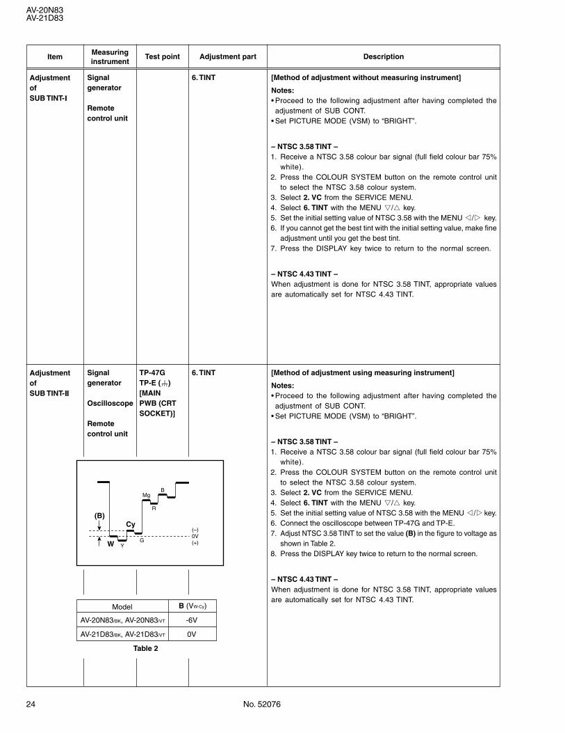
6. TINT [Method of adjustment using measuring instrument]
Notes:• Proceed to the following adjustment after having completed theadjustment of SUB CONT.
• Set PICTURE MODE (VSM) to “BRIGHT”.
– NTSC 3.58 TINT –1. Receive a NTSC 3.58 colour bar signal (full field colour bar 75%
white).2. Press the COLOUR SYSTEM button on the remote control unit
to select the NTSC 3.58 colour system.3. Select 2. VC from the SERVICE MENU.4. Select 6. TINT with the MENU &/^ key.5. Set the initial setting value of NTSC 3.58 with the MENU */Tkey.6. Connect the oscilloscope between TP-47G and TP-E.7. Adjust NTSC 3.58 TINT to set the value (B) in the figure to voltage as
shown in Table 2.8. Press the DISPLAY key twice to return to the normal screen.
– NTSC 4.43 TINT –When adjustment is done for NTSC 3.58 TINT, appropriate valuesare automatically set for NTSC 4.43 TINT.
TP-47GTP-E (H)[MAINPWB (CRTSOCKET)]
Table 2
Model B (VW-Cy)
AV-20N83/BK, AV-20N83/VT -6V
AV-21D83/BK, AV-21D83/VT 0V
No. 52076 25
AV-20N83AV-21D83
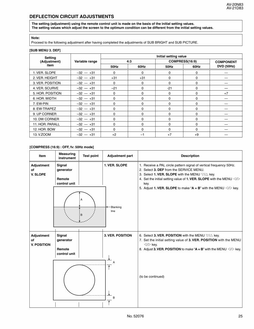
DEFLECTION CIRCUIT ADJUSTMENTS
[SUB MENU 3. DEF]
1. VER. SLOPE –32 — +31 0 0 0 0 —
2. VER. HEIGHT –32 — +31 +31 +31 0 0 —
3. VER. POSITION –32 — +31 0 0 0 0 —
4. VER. SCURVE –32 — +31 –21 0 -21 0 —
5. HOR. POSITION –32 — +31 0 0 0 0 +7
6. HOR. WIDTH –32 — +31 0 0 0 0 —
7. EW-PIN –32 — +31 0 0 0 0 —
8. EW-TRAPEZ –32 — +31 0 0 0 0 —
9. UP CORNER –32 — +31 0 0 0 0 —
10. DW CORNER –32 — +31 0 0 0 0 —
11. HOR. PARALL –32 — +31 0 0 0 0 —
12. HOR. BOW –32 — +31 0 0 0 0 —
13. V.ZOOM –32 — +31 +2 –1 +7 +9 —
ItemMeasuringinstrument
Test point Adjustment part Description
AdjustmentofV. SLOPE
Signalgenerator
Remotecontrol unit
1. VER. SLOPE 1. Receive a PAL circle pattern signal of vertical frequency 50Hz.2. Select 3. DEF from the SERVICE MENU.3. Select 1. VER. SLOPE with the MENU &/^ key.4. Set the initial setting value of 1. VER. SLOPE with the MENU */T
key.5. Adjust 1. VER. SLOPE to make “A = B” with the MENU */Tkey.
B
A
Blanking line
AdjustmentofV. POSITION
Signalgenerator
Remotecontrol unit
3. VER. POSITION 6. Select 3. VER. POSITION with the MENU &/^ key.7. Set the initial setting value of 3. VER. POSITION with the MENU
*/Tkey.8. Adjust 3. VER. POSITION to make “A = B” with the MENU */Tkey.
(to be continued)
The setting (adjustment) using the remote control unit is made on the basis of the initial setting values.The setting values which adjust the screen to the optimum condition can be different from the initial setting values.
A
B
Note:Proceed to the following adjustment after having completed the adjustments of SUB BRIGHT and SUB PICTURE.
[COMPRESS (16:9) : OFF, fv: 50Hz mode]
Initial setting value
Variable range COMPONENTDVD (50Hz)50Hz
COMPRESS(16:9)Setting
(Adjustment)item 60Hz
4:3
50Hz 60Hz
26 No. 52076
AV-20N83AV-21D83
ItemMeasuringinstrument
Test point Adjustment part Description
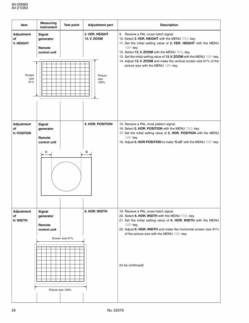
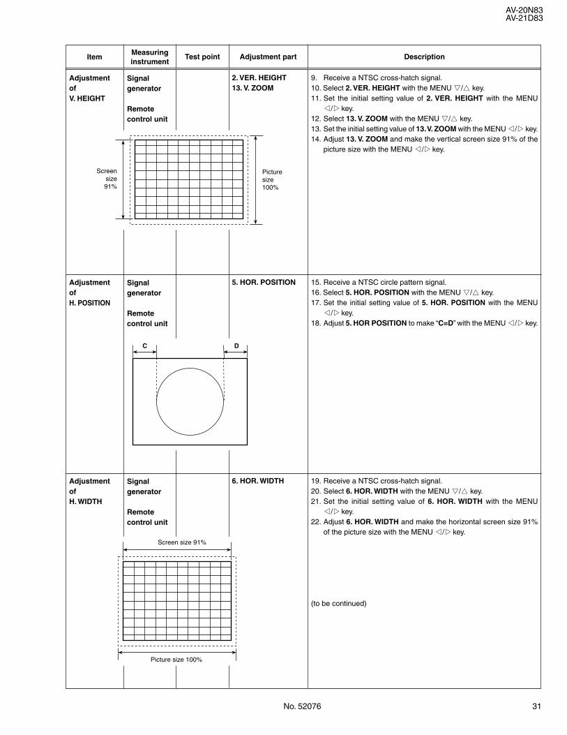
AdjustmentofV. HEIGHT
2. VER. HEIGHT13. V. ZOOM
9. Receive a PAL cross-hatch signal.10. Select 2. VER. HEIGHT with the MENU &/^ key.11. Set the initial setting value of 2. VER. HEIGHT with the MENU
*/Tkey.12. Select 13. V. ZOOM with the MENU &/^ key.13. Set the initial setting value of 13. V. ZOOM with the MENU */Tkey.14. Adjust 13. V. ZOOM and make the vertical screen size 91% of the
picture size with the MENU */Tkey.
Signalgenerator
Remotecontrol unit
AdjustmentofH. POSITION
5. HOR. POSITION 15. Receive a PAL circle pattern signal.16. Select 5. HOR. POSITION with the MENU &/^ key.17. Set the initial setting value of 5. HOR. POSITION with the MENU
*/Tkey.18. Adjust 5. HOR POSITION to make “C=D” with the MENU */Tkey.
Signalgenerator
Remotecontrol unit
Screensize91%
Picturesize100%
C D
AdjustmentofH. WIDTH
6. HOR. WIDTH 19. Receive a PAL cross-hatch signal.20. Select 6. HOR. WIDTH with the MENU &/^ key.21. Set the initial setting value of 6. HOR. WIDTH with the MENU
*/Tkey.22. Adjust 6. HOR. WIDTH and make the horizontal screen size 91%
of the picture size with the MENU */Tkey.
(to be continued)
Signalgenerator
Remotecontrol unit
Screen size 91%
Picture size 100%
No. 52076 27
AV-20N83AV-21D83
ItemMeasuringinstrument
Test point Adjustment part Description
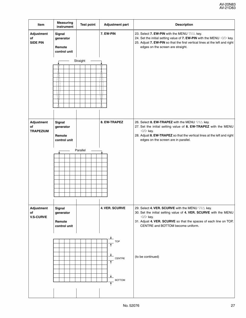
AdjustmentofSIDE PIN
7. EW-PIN 23. Select 7. EW-PIN with the MENU &/^ key.24. Set the initial setting value of 7. EW-PIN with the MENU */Tkey.25. Adjust 7. EW-PIN so that the first vertical lines at the left and right
edges on the screen are straight.
Signalgenerator
Remotecontrol unit
AdjustmentofTRAPEZIUM
8. EW-TRAPEZ 26. Select 8. EW-TRAPEZ with the MENU &/^ key.27. Set the initial setting value of 8. EW-TRAPEZ with the MENU
*/Tkey.28. Adjust 8. EW-TRAPEZ so that the vertical lines at the left and right
edges on the screen are in parallel.
Signalgenerator
Remotecontrol unit
AdjustmentofV.S-CURVE
4. VER. SCURVE 29. Select 4. VER. SCURVE with the MENU &/^ key.30. Set the initial setting value of 4. VER. SCURVE with the MENU
*/Tkey.31. Adjust 4. VER. SCURVE so that the spaces of each line on TOP,
CENTRE and BOTTOM become uniform.
(to be continued)
Signalgenerator
Remotecontrol unit
Straight
Parallel
TOP
CENTRE
BOTTOM
28 No. 52076
AV-20N83AV-21D83
ItemMeasuringinstrument
Test point Adjustment part Description
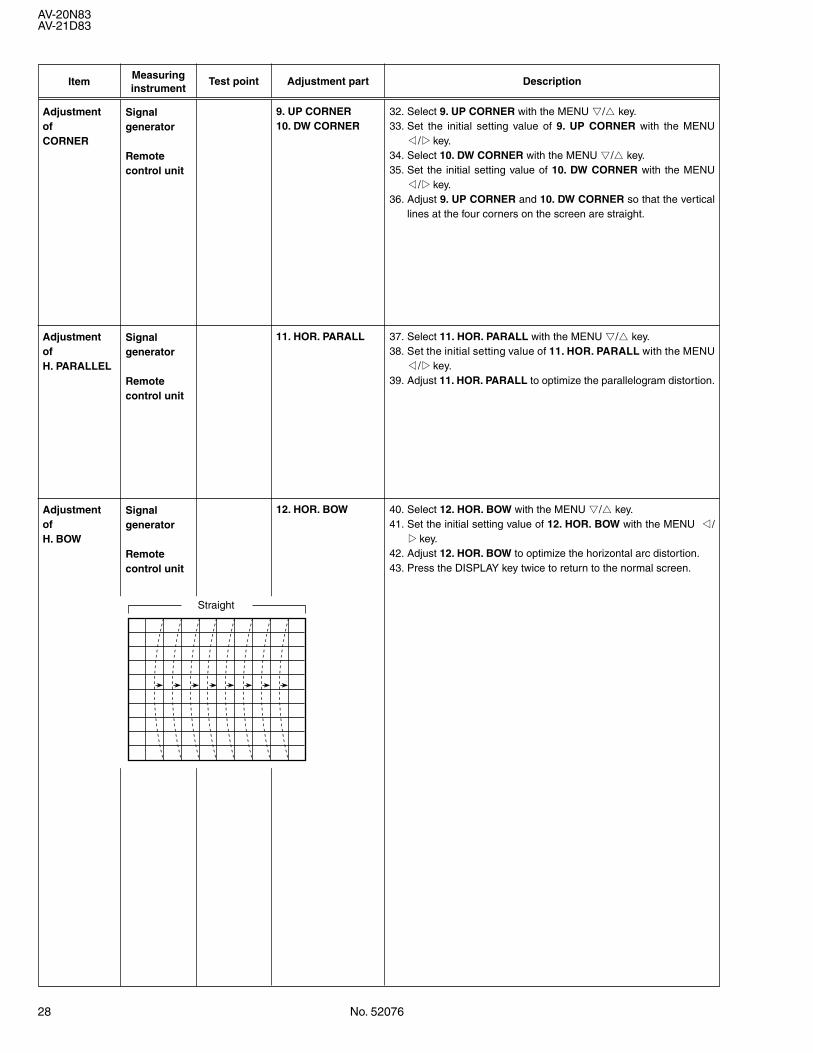
AdjustmentofCORNER
9. UP CORNER10. DW CORNER
32. Select 9. UP CORNER with the MENU &/^ key.33. Set the initial setting value of 9. UP CORNER with the MENU
*/Tkey.34. Select 10. DW CORNER with the MENU &/^ key.35. Set the initial setting value of 10. DW CORNER with the MENU
*/Tkey.36. Adjust 9. UP CORNER and 10. DW CORNER so that the vertical
lines at the four corners on the screen are straight.
Signalgenerator
Remotecontrol unit
AdjustmentofH. PARALLEL
11. HOR. PARALL 37. Select 11. HOR. PARALL with the MENU &/^ key.38. Set the initial setting value of 11. HOR. PARALL with the MENU
*/Tkey.39. Adjust 11. HOR. PARALL to optimize the parallelogram distortion.
Signalgenerator
Remotecontrol unit
AdjustmentofH. BOW
12. HOR. BOW 40. Select 12. HOR. BOW with the MENU &/^ key.41. Set the initial setting value of 12. HOR. BOW with the MENU */
Tkey.42. Adjust 12. HOR. BOW to optimize the horizontal arc distortion.43. Press the DISPLAY key twice to return to the normal screen.
Signalgenerator
Remotecontrol unit
Straight
No. 52076 29
AV-20N83AV-21D83
ItemMeasuringinstrument
Test point Adjustment part Description
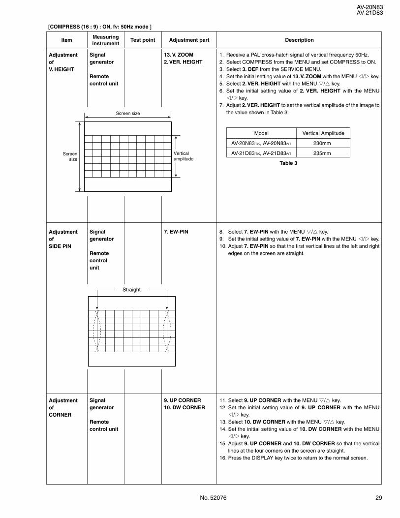
[COMPRESS (16 : 9) : ON, fv: 50Hz mode ]
1. Receive a PAL cross-hatch signal of vertical frrequency 50Hz.2. Select COMPRESS from the MENU and set COMPRESS to ON.3. Select 3. DEF from the SERVICE MENU.4. Set the initial setting value of 13. V. ZOOM with the MENU */Tkey.5. Select 2. VER. HEIGHT with the MENU &/^ key.6. Set the initial setting value of 2. VER. HEIGHT with the MENU
*/Tkey.7. Adjust 2. VER. HEIGHT to set the vertical amplitude of the image to
the value shown in Table 3.
AdjustmentofV. HEIGHT
AdjustmentofSIDE PIN
8. Select 7. EW-PIN with the MENU &/^ key.9. Set the initial setting value of 7. EW-PIN with the MENU */Tkey.10. Adjust 7. EW-PIN so that the first vertical lines at the left and right
edges on the screen are straight.
7. EW-PIN
AdjustmentofCORNER
Signalgenerator
Remotecontrol unit
11. Select 9. UP CORNER with the MENU &/^ key.12. Set the initial setting value of 9. UP CORNER with the MENU
*/Tkey.13. Select 10. DW CORNER with the MENU &/^ key.14. Set the initial setting value of 10. DW CORNER with the MENU
*/Tkey.15. Adjust 9. UP CORNER and 10. DW CORNER so that the vertical
lines at the four corners on the screen are straight.16. Press the DISPLAY key twice to return to the normal screen.
9. UP CORNER10. DW CORNER
Screen size
Verticalamplitude
Screen size
Straight
Signalgenerator
Remotecontrol unit
Signalgenerator
Remotecontrolunit
13. V. ZOOM2. VER. HEIGHT
Vertical Amplitude
AV-20N83/BK, AV-20N83/VT 230mm
AV-21D83/BK, AV-21D83/VT 235mm
Table 3
Model
30 No. 52076
AV-20N83AV-21D83
ItemMeasuringinstrument
Test point Adjustment part Description
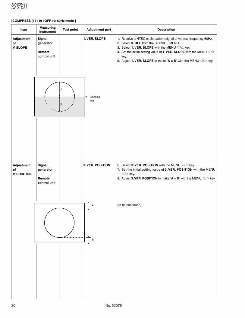
AdjustmentofV. SLOPE
Signalgenerator
Remotecontrol unit
1. VER. SLOPE 1. Receive a NTSC circle pattern signal of vertical frequency 60Hz.2. Select 3. DEF from the SERVICE MENU.3. Select 1. VER. SLOPE with the MENU &/^ key.4. Set the initial setting value of 1. VER. SLOPE with the MENU */T
key.5. Adjust 1. VER. SLOPE to make “A = B” with the MENU */Tkey.
B
A
Blanking line
AdjustmentofV. POSITION
Signalgenerator
Remotecontrol unit
3. VER. POSITION 6. Select 3. VER. POSITION with the MENU &/^ key.7. Set the initial setting value of 3. VER. POSITION with the MENU
*/Tkey.8. Adjust 3. VER. POSITION to make “A = B” with the MENU */Tkey.
(to be continued)A
B
[COMPRESS (16 : 9) : OFF, fv: 60Hz mode ]
No. 52076 31
AV-20N83AV-21D83
ItemMeasuringinstrument
Test point Adjustment part Description
AdjustmentofV. HEIGHT
2. VER. HEIGHT13. V. ZOOM
9. Receive a NTSC cross-hatch signal.10. Select 2. VER. HEIGHT with the MENU &/^ key.11. Set the initial setting value of 2. VER. HEIGHT with the MENU
*/Tkey.12. Select 13. V. ZOOM with the MENU &/^ key.13. Set the initial setting value of 13. V. ZOOM with the MENU */Tkey.14. Adjust 13. V. ZOOM and make the vertical screen size 91% of the
picture size with the MENU */Tkey.
Signalgenerator
Remotecontrol unit
AdjustmentofH. POSITION
5. HOR. POSITION 15. Receive a NTSC circle pattern signal.16. Select 5. HOR. POSITION with the MENU &/^ key.17. Set the initial setting value of 5. HOR. POSITION with the MENU
*/Tkey.18. Adjust 5. HOR POSITION to make “C=D” with the MENU */Tkey.
Signalgenerator
Remotecontrol unit
Screensize91%
Picturesize100%
C D
AdjustmentofH. WIDTH
6. HOR. WIDTH 19. Receive a NTSC cross-hatch signal.20. Select 6. HOR. WIDTH with the MENU &/^ key.21. Set the initial setting value of 6. HOR. WIDTH with the MENU
*/Tkey.22. Adjust 6. HOR. WIDTH and make the horizontal screen size 91%
of the picture size with the MENU */Tkey.
(to be continued)
Signalgenerator
Remotecontrol unit
Screen size 91%
Picture size 100%
32 No. 52076
AV-20N83AV-21D83
ItemMeasuringinstrument
Test point Adjustment part Description
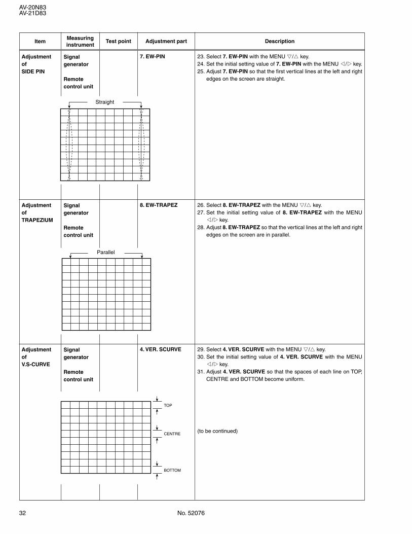
AdjustmentofSIDE PIN
7. EW-PIN 23. Select 7. EW-PIN with the MENU &/^ key.24. Set the initial setting value of 7. EW-PIN with the MENU */Tkey.25. Adjust 7. EW-PIN so that the first vertical lines at the left and right
edges on the screen are straight.
Signalgenerator
Remotecontrol unit
AdjustmentofTRAPEZIUM
8. EW-TRAPEZ 26. Select 8. EW-TRAPEZ with the MENU &/^ key.27. Set the initial setting value of 8. EW-TRAPEZ with the MENU
*/Tkey.28. Adjust 8. EW-TRAPEZ so that the vertical lines at the left and right
edges on the screen are in parallel.
Signalgenerator
Remotecontrol unit
AdjustmentofV.S-CURVE
4. VER. SCURVE 29. Select 4. VER. SCURVE with the MENU &/^ key.30. Set the initial setting value of 4. VER. SCURVE with the MENU
*/Tkey.31. Adjust 4. VER. SCURVE so that the spaces of each line on TOP,
CENTRE and BOTTOM become uniform.
(to be continued)
Signalgenerator
Remotecontrol unit
Straight
Parallel
TOP
CENTRE
BOTTOM
No. 52076 33
AV-20N83AV-21D83
ItemMeasuringinstrument
Test point Adjustment part Description
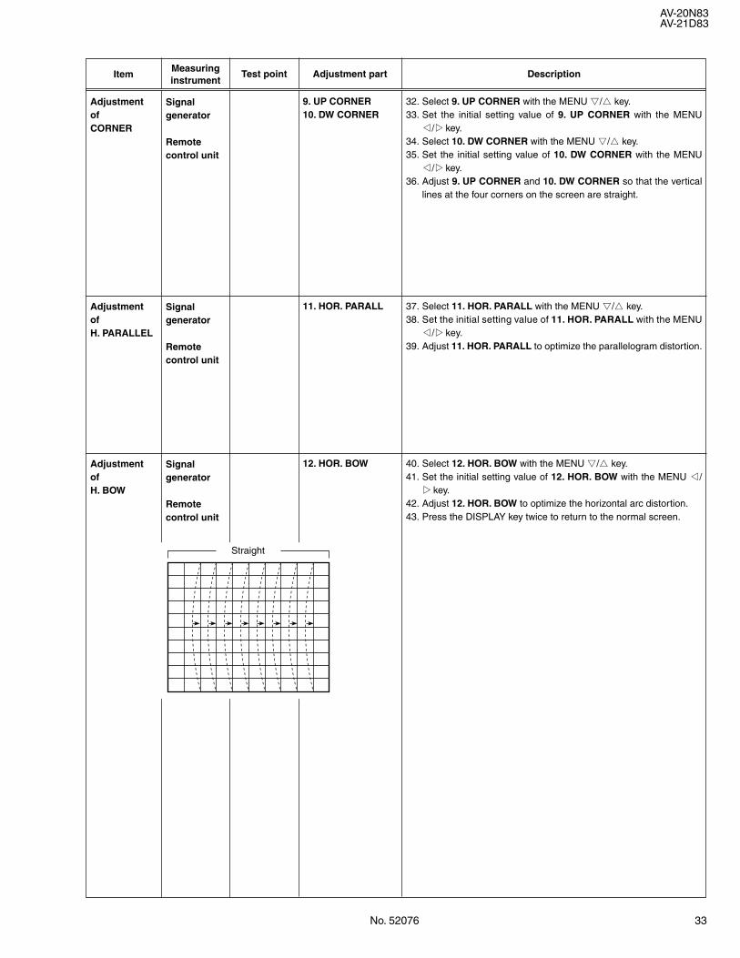
AdjustmentofCORNER
9. UP CORNER10. DW CORNER
32. Select 9. UP CORNER with the MENU &/^ key.33. Set the initial setting value of 9. UP CORNER with the MENU
*/Tkey.34. Select 10. DW CORNER with the MENU &/^ key.35. Set the initial setting value of 10. DW CORNER with the MENU
*/Tkey.36. Adjust 9. UP CORNER and 10. DW CORNER so that the vertical
lines at the four corners on the screen are straight.
Signalgenerator
Remotecontrol unit
AdjustmentofH. PARALLEL
11. HOR. PARALL 37. Select 11. HOR. PARALL with the MENU &/^ key.38. Set the initial setting value of 11. HOR. PARALL with the MENU
*/Tkey.39. Adjust 11. HOR. PARALL to optimize the parallelogram distortion.
Signalgenerator
Remotecontrol unit
AdjustmentofH. BOW
12. HOR. BOW 40. Select 12. HOR. BOW with the MENU &/^ key.41. Set the initial setting value of 12. HOR. BOW with the MENU */
Tkey.42. Adjust 12. HOR. BOW to optimize the horizontal arc distortion.43. Press the DISPLAY key twice to return to the normal screen.
Signalgenerator
Remotecontrol unit
Straight
34 No. 52076
AV-20N83AV-21D83
ItemMeasuringinstrument
Test point Adjustment part Description
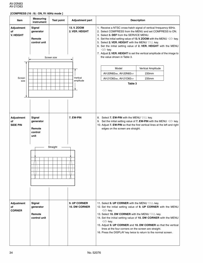
[COMPRESS (16 : 9) : ON, fV: 60Hz mode ]
1. Receive a NTSC cross-hatch signal of vertical frrequency 60Hz.2. Select COMPRESS from the MENU and set COMPRESS to ON.3. Select 3. DEF from the SERVICE MENU.4. Set the initial setting value of 13. V. ZOOM with the MENU */Tkey.5. Select 2. VER. HEIGHT with the MENU &/^ key.6. Set the initial setting value of 2. VER. HEIGHT with the MENU
*/Tkey.7. Adjust 2. VER. HEIGHT to set the vertical amplitude of the image to
the value shown in Table 3.
AdjustmentofV. HEIGHT
AdjustmentofSIDE PIN
8. Select 7. EW-PIN with the MENU &/^ key.9. Set the initial setting value of 7. EW-PIN with the MENU */Tkey.10. Adjust 7. EW-PIN so that the first vertical lines at the left and right
edges on the screen are straight.
7. EW-PIN
AdjustmentofCORNER
Signalgenerator
Remotecontrol unit
11. Select 9. UP CORNER with the MENU &/^ key.12. Set the initial setting value of 9. UP CORNER with the MENU
*/Tkey.13. Select 10. DW CORNER with the MENU &/^ key.14. Set the initial setting value of 10. DW CORNER with the MENU
*/Tkey.15. Adjust 9. UP CORNER and 10. DW CORNER so that the vertical
lines at the four corners on the screen are straight.16. Press the DISPLAY key twice to return to the normal screen.
9. UP CORNER10. DW CORNER
Screen size
Verticalamplitude
Screen size
Straight
Signalgenerator
Remotecontrol unit
Signalgenerator
Remotecontrolunit
13. V. ZOOM2. VER. HEIGHT
Vertical Amplitude
AV-20N83/BK, AV-20N83/VT 230mm
AV-21D83/BK, AV-21D83/VT 235mm
Table 3
Model
No. 52076 35
AV-20N83AV-21D83
ItemMeasuringinstrument Test point Adjustment part Description
VSM PRESET SETTING
ItemMeasuringinstrument
Test point Adjustment part Description
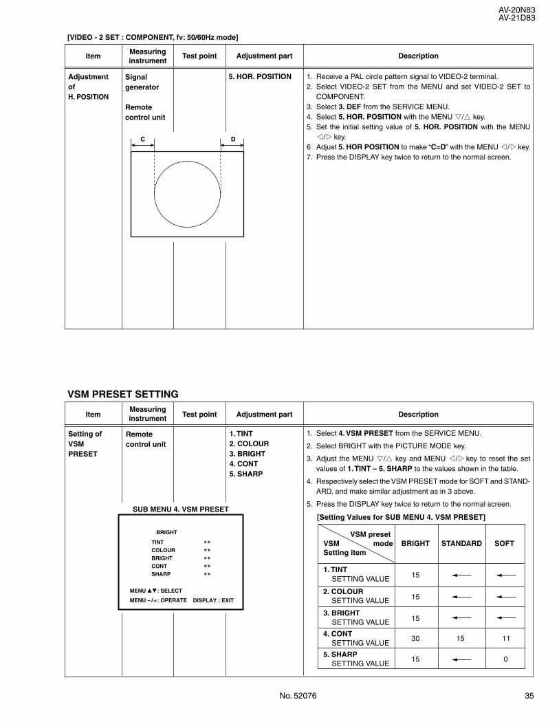
AdjustmentofH. POSITION
5. HOR. POSITION 1. Receive a PAL circle pattern signal to VIDEO-2 terminal.2. Select VIDEO-2 SET from the MENU and set VIDEO-2 SET to
COMPONENT.3. Select 3. DEF from the SERVICE MENU.4. Select 5. HOR. POSITION with the MENU &/^ key.5. Set the initial setting value of 5. HOR. POSITION with the MENU
*/Tkey.6 Adjust 5. HOR POSITION to make “C=D” with the MENU */Tkey.7. Press the DISPLAY key twice to return to the normal screen.
Signalgenerator
Remotecontrol unit
C D
[VIDEO - 2 SET : COMPONENT, fv: 50/60Hz mode]
Setting ofVSMPRESET
1. TINT2. COLOUR3. BRIGHT4. CONT5. SHARP
Remotecontrol unit
1. Select 4. VSM PRESET from the SERVICE MENU.
2. Select BRIGHT with the PICTURE MODE key.
3. Adjust the MENU &/^ key and MENU */Tkey to reset the setvalues of 1. TINT – 5. SHARP to the values shown in the table.
4. Respectively select the VSM PRESET mode for SOFT and STAND-ARD, and make similar adjustment as in 3 above.
5. Press the DISPLAY key twice to return to the normal screen.SUB MENU 4. VSM PRESET
TINT **COLOUR **BRIGHT **CONT **SHARP **
BRIGHT
MENU 89: SELECT
MENU - /+: OPERATE DISPLAY : EXIT
VSM presetVSM mode BRIGHT STANDARD SOFTSetting item
1. TINT SETTING VALUE
2. COLOUR SETTING VALUE
3. BRIGHT SETTING VALUE
4. CONT30
15
15
15
15 0
15 11 SETTING VALUE
5. SHARP SETTING VALUE
[Setting Values for SUB MENU 4. VSM PRESET]
36 No. 52076
AV-20N83AV-21D83
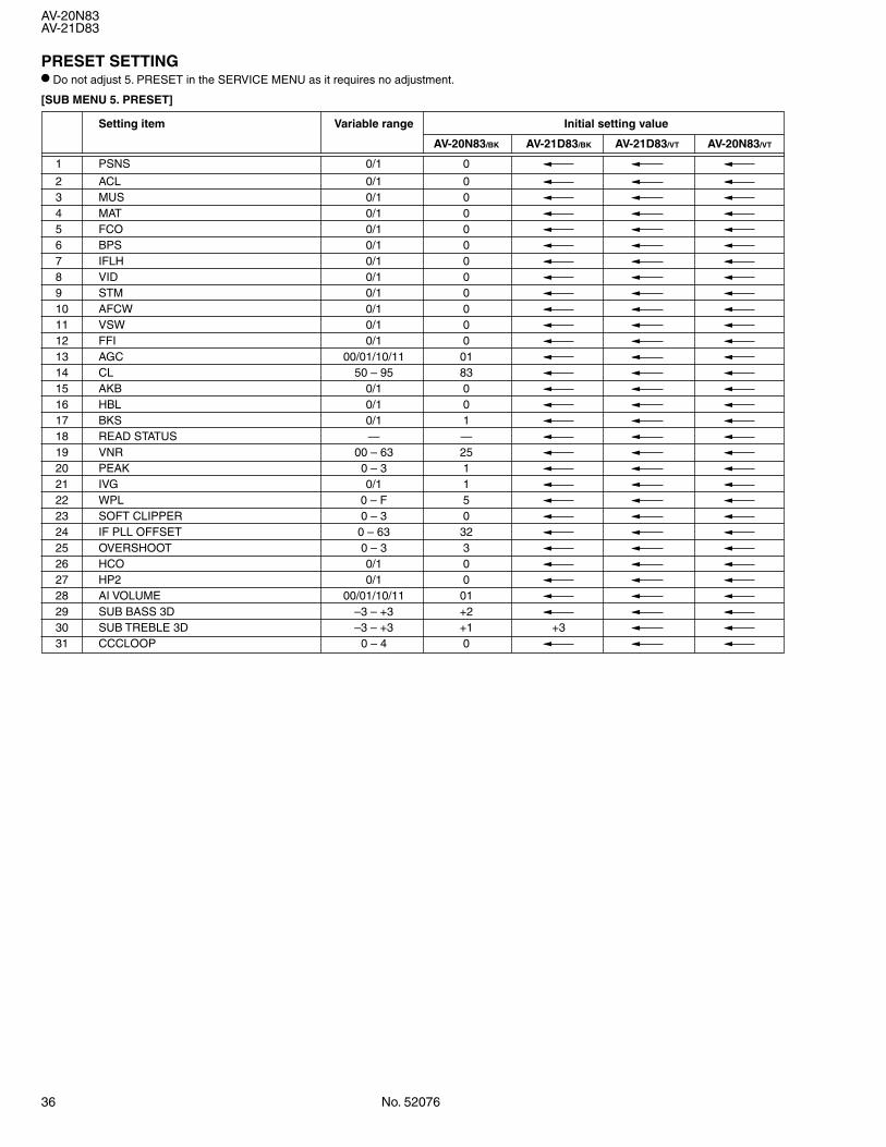
PRESET SETTING• Do not adjust 5. PRESET in the SERVICE MENU as it requires no adjustment.
[SUB MENU 5. PRESET]
Setting item Variable range Initial setting value
AV-20N83/BK AV-21D83/BK AV-21D83/VT AV-20N83/VT
1 PSNS 0/1 0
2 ACL 0/1 03 MUS 0/1 04 MAT 0/1 05 FCO 0/1 06 BPS 0/1 07 IFLH 0/1 08 VID 0/1 09 STM 0/1 010 AFCW 0/1 011 VSW 0/1 012 FFI 0/1 013 AGC 00/01/10/11 0114 CL 50 – 95 8315 AKB 0/1 016 HBL 0/1 017 BKS 0/1 118 READ STATUS — —19 VNR 00 – 63 2520 PEAK 0 – 3 121 IVG 0/1 122 WPL 0 – F 523 SOFT CLIPPER 0 – 3 024 IF PLL OFFSET 0 – 63 3225 OVERSHOOT 0 – 3 326 HCO 0/1 027 HP2 0/1 028 AI VOLUME 00/01/10/11 0129 SUB BASS 3D –3 – +3 +230 SUB TREBLE 3D –3 – +3 +1 +331 CCCLOOP 0 – 4 0
No. 52076 37
AV-20N83AV-21D83
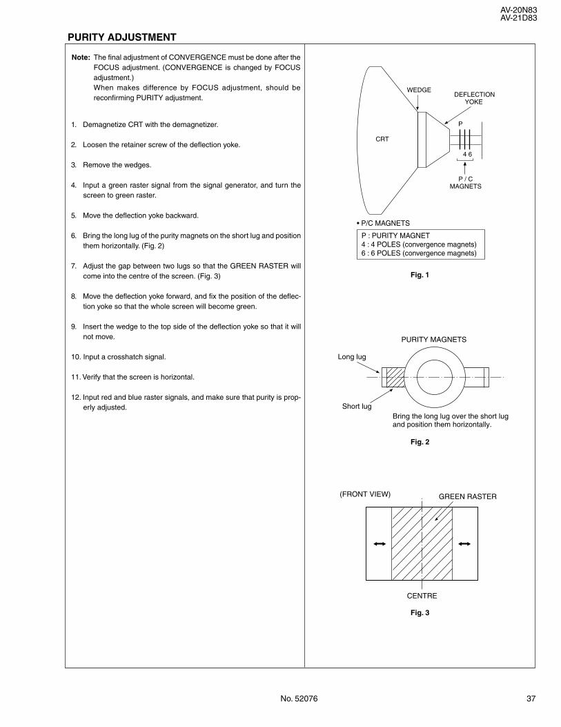
PURITY ADJUSTMENT
Note: The final adjustment of CONVERGENCE must be done after theFOCUS adjustment. (CONVERGENCE is changed by FOCUSadjustment.)When makes difference by FOCUS adjustment, should bereconfirming PURITY adjustment.
1. Demagnetize CRT with the demagnetizer.
2. Loosen the retainer screw of the deflection yoke.
3. Remove the wedges.
4. Input a green raster signal from the signal generator, and turn thescreen to green raster.
5. Move the deflection yoke backward.
6. Bring the long lug of the purity magnets on the short lug and positionthem horizontally. (Fig. 2)
7. Adjust the gap between two lugs so that the GREEN RASTER willcome into the centre of the screen. (Fig. 3)
8. Move the deflection yoke forward, and fix the position of the deflec-tion yoke so that the whole screen will become green.
9. Insert the wedge to the top side of the deflection yoke so that it willnot move.
10. Input a crosshatch signal.
11. Verify that the screen is horizontal.
12. Input red and blue raster signals, and make sure that purity is prop-erly adjusted.
Fig. 1
• P/C MAGNETS
P : PURITY MAGNET4 : 4 POLES (convergence magnets)6 : 6 POLES (convergence magnets)
CRT
WEDGE
P
P / CMAGNETS
4 6
DEFLECTION YOKE
Fig. 2
Long lug
Short lug
PURITY MAGNETS
Bring the long lug over the short lugand position them horizontally.
Fig. 3
(FRONT VIEW) GREEN RASTER
CENTRE
38 No. 52076
AV-20N83AV-21D83
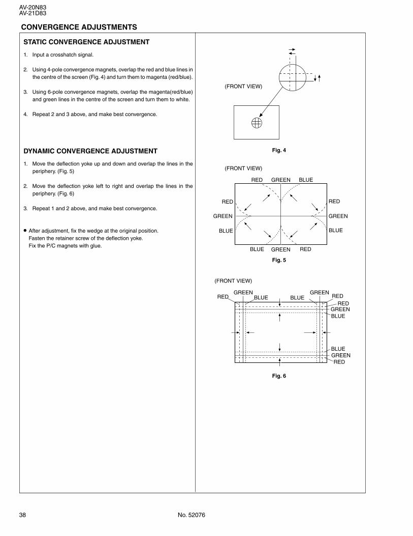
STATIC CONVERGENCE ADJUSTMENT
1. Input a crosshatch signal.
2. Using 4-pole convergence magnets, overlap the red and blue lines inthe centre of the screen (Fig. 4) and turn them to magenta (red/blue).
3. Using 6-pole convergence magnets, overlap the magenta(red/blue)and green lines in the centre of the screen and turn them to white.
4. Repeat 2 and 3 above, and make best convergence.
DYNAMIC CONVERGENCE ADJUSTMENT
1. Move the deflection yoke up and down and overlap the lines in theperiphery. (Fig. 5)
2. Move the deflection yoke left to right and overlap the lines in theperiphery. (Fig. 6)
3. Repeat 1 and 2 above, and make best convergence.
• After adjustment, fix the wedge at the original position.Fasten the retainer screw of the deflection yoke.Fix the P/C magnets with glue.
RED
REDRED
RED
BLUE
(FRONT VIEW)
(FRONT VIEW)
BLUEBLUE
BLUE GREEN
GREENGREEN
GREEN
(FRONT VIEW)
GREEN GREEN
GREEN
GREEN
RED REDRED
RED
BLUE
BLUE
BLUE
BLUE
Fig. 4
Fig. 5
Fig. 6
CONVERGENCE ADJUSTMENTS
No. 52076 39
AV-20N83AV-21D83
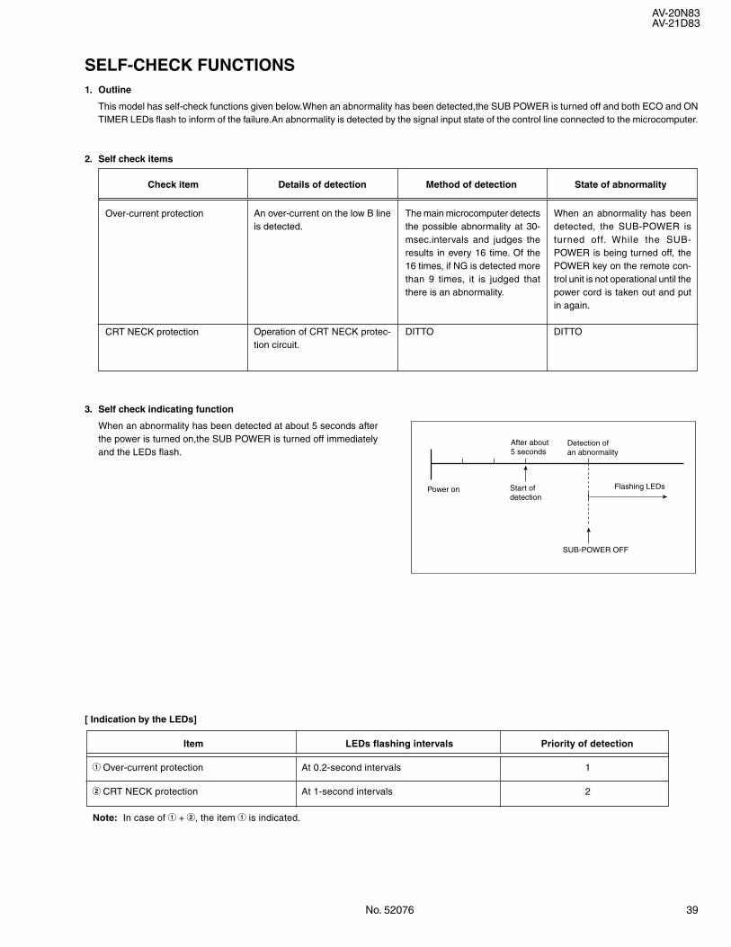
SELF-CHECK FUNCTIONS1. Outline
This model has self-check functions given below.When an abnormality has been detected,the SUB POWER is turned off and both ECO and ONTIMER LEDs flash to inform of the failure.An abnormality is detected by the signal input state of the control line connected to the microcomputer.
2. Self check items
Check item Details of detection Method of detection State of abnormality
3. Self check indicating function
When an abnormality has been detected at about 5 seconds afterthe power is turned on,the SUB POWER is turned off immediatelyand the LEDs flash.
Over-current protection
CRT NECK protection
An over-current on the low B lineis detected.
Operation of CRT NECK protec-tion circuit.
The main microcomputer detectsthe possible abnormality at 30-msec.intervals and judges theresults in every 16 time. Of the16 times, if NG is detected morethan 9 times, it is judged thatthere is an abnormality.
DITTO
When an abnormality has beendetected, the SUB-POWER isturned off. While the SUB-POWER is being turned off, thePOWER key on the remote con-trol unit is not operational until thepower cord is taken out and putin again.
DITTO
[ Indication by the LEDs]
Item LEDs flashing intervals Priority of detection
1 Over-current protection At 0.2-second intervals 1
2 CRT NECK protection At 1-second intervals 2
Note: In case of 1 + 2, the item 1 is indicated.
After about5 seconds
Power on Start ofdetection
Detection ofan abnormality
SUB-POWER OFF
Flashing LEDs
40 No. 52076
AV-20N83AV-21D83
SERVICE NOTE :

Printed in Japan0212 WPC
VICTOR COMPANY OF JAPAN, LIMITED 12,3-chome,Moriya-cho,Kanagawa-ku,Yokohama,Kanagawa-prefecture,221-8528,JapanHOME AV NETWORK BUSINESS UNIT
#4#4
AV20N83BK-BKAV21D83BK-BK
AV21D83VT-CKAV20N83VT-CK
#4#4


![1st Edition SERVICE MANUAL - Diagramas dediagramas.diagramasde.com/televisores/29LFG1L.pdf · IMPORTANT SERVICE NOTES [1] ... SOLID STATE DEVICE BASE DIAGRAM [1] ... sure it's go](https://img.pdfslide.us/doc/110x75/5aa771047f8b9aee748c102f/1st-edition-service-manual-diagramas-service-notes-1-solid-state-device.jpg)