Embed Size (px)
Citation preview
PLASMA TVSERVICE MANUAL
CAUTIONBEFORE SERVICING THE CHASSIS,READ THE SAFETY PRECAUTIONS IN THIS MANUAL.
CHASSIS : PU84C
MODEL : 50PG30 50PG30F-UA
CANADA : http//biz.lgservice.comUSA : http//www.lgservice.com
: http//biz.lgservice.com
Internal Use Only
CHVOLMENUINPUT ENTER
- 2 -Copyright©2008 LG Electronics. Inc. All right reserved. Only for training and service purposes
LGE Internal Use Only
SAFETY PRECAUTIONS
Many electrical and mechanical parts in this chassis have special safety-related characteristics. These parts are identified by in theSchematic Diagram and Replacement Parts List. It is essential that these special safety parts should be replaced with the same components as recommended in this manual to preventX-RADIATION, Shock, Fire, or other Hazards. Do not modify the original design without permission of manufacturer.
General Guidance
An lsolation Transformer should always be used during theservicing of a receiver whose chassis is not isolated from the ACpower line. Use a transformer of adequate power rating as thisprotects the technician from accidents resulting in personal injuryfrom electrical shocks.
It will also protect the receiver and it's components from beingdamaged by accidental shorts of the circuitary that may beinadvertently introduced during the service operation.
If any fuse (or Fusible Resistor) in this monitor is blown, replace itwith the same specified type.
When replacing a high wattage resistor (Oxide Metal Film Resistor,over 1W), keep the resistor 10mm away from PCB.
Keep wires away from high voltage or high temperature parts.
Leakage Current Cold Check(Antenna Cold Check)With the instrument AC plug removed from AC source, connect anelectrical jumper across the two AC plug prongs. Place the ACswitch in the on positioin, connect one lead of ohm-meter to the ACplug prongs tied together and touch other ohm-meter lead in turn toeach exposed metallic parts such as antenna terminals, phonejacks, etc. If the exposed metallic part has a return path to the chassis, themeasured resistance should be between 1MΩ and 5.2MΩ. When the exposed metal has no return path to the chassis thereading must be infinite.An other abnormality exists that must be corrected before thereceiver is returned to the customer.
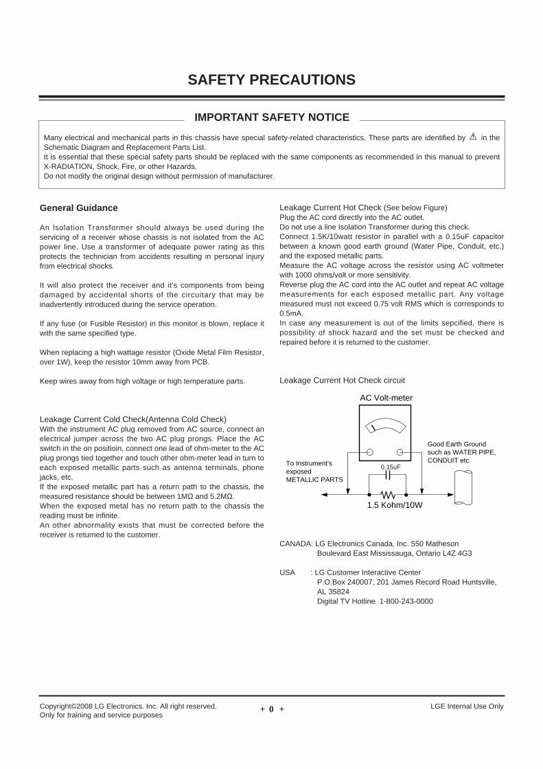
Leakage Current Hot Check (See below Figure) Plug the AC cord directly into the AC outlet.Do not use a line Isolation Transformer during this check. Connect 1.5K/10watt resistor in parallel with a 0.15uF capacitorbetween a known good earth ground (Water Pipe, Conduit, etc.)and the exposed metallic parts.Measure the AC voltage across the resistor using AC voltmeterwith 1000 ohms/volt or more sensitivity.Reverse plug the AC cord into the AC outlet and repeat AC voltagemeasurements for each esposed metallic part. Any voltagemeasured must not exceed 0.75 volt RMS which is corresponds to0.5mA.In case any measurement is out of the limits sepcified, there ispossibility of shock hazard and the set must be checked andrepaired before it is returned to the customer.
Leakage Current Hot Check circuit
CANADA: LG Electronics Canada, Inc. 550 MathesonBoulevard East Mississauga, Ontario L4Z 4G3
USA : LG Customer Interactive CenterP.O.Box 240007, 201 James Record Road Huntsville,AL 35824Digital TV Hotline 1-800-243-0000
1.5 Kohm/10W
To Instrument'sexposed METALLIC PARTS
Good Earth Groundsuch as WATER PIPE,CONDUIT etc.
AC Volt-meter
IMPORTANT SAFETY NOTICE
0.15uF
- 3 -Copyright©2008 LG Electronics. Inc. All right reserved. Only for training and service purposes
LGE Internal Use Only
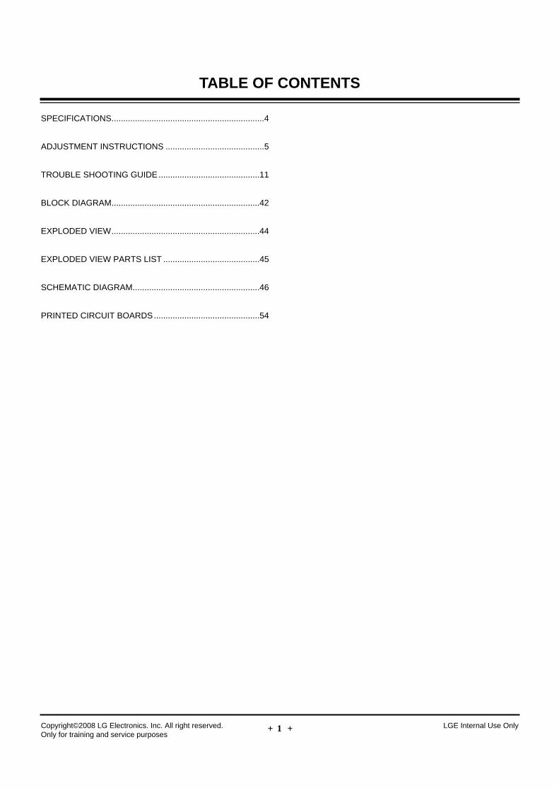
SPECIFICATIONS.................................................................4
ADJUSTMENT INSTRUCTIONS ..........................................5
TROUBLE SHOOTING GUIDE...........................................11
BLOCK DIAGRAM...............................................................42
EXPLODED VIEW...............................................................44
EXPLODED VIEW PARTS LIST .........................................45
SCHEMATIC DIAGRAM......................................................46
PRINTED CIRCUIT BOARDS.............................................54
TABLE OF CONTENTS
- 4 -Copyright©2008 LG Electronics. Inc. All right reserved. Only for training and service purposes
LGE Internal Use Only
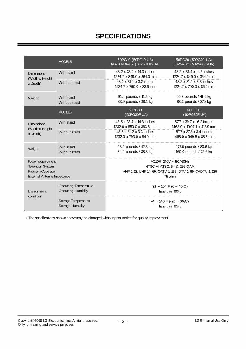
n The specifications shown above may be changed without prior notice for quality improvement.
MODELS
AC100-240V ~ 50 /60HzNTSC-M, ATSC, 64 & 256 QAM
VHF 2-13, UHF 14-69, CATV 1-135, DTV 2-69, CADTV 1-13575 ohm
32 ~ 104¡F (0 ~ 40¡C)Less than 80%
-4 ~ 140¡F (-20 ~ 60¡C)Less than 85%
Dimensions(Width x Height x Depth)
Weight
Power requirementTelevision SystemProgram CoverageExternal Antenna Impedance
Environment condition
With stand
Without stand
With standWithout stand
Operating TemperatureOperating Humidity
Storage TemperatureStorage Humidity
50PG10 (50PG10-UA)NS-50PDP-09 (50PG1DD-UA)
MODELS 50PG30(50PG30F-UA)
60PG30(60PG30F-UA)
48.2 x 33.4 x 14.3 inches1224.7 x 849.0 x 364.0 mm
48.2 x 31.1 x 3.2 inches1224.7 x 790.0 x 83.6 mm
91.4 pounds / 41.5 kg83.9 pounds / 38.1 kg
50PG20 (50PG20-UA)50PG20C (50PG20C-UA)
48.2 x 33.4 x 14.3 inches1224.7 x 849.0 x 364.0 mm
48.2 x 31.1 x 3.3 inches1224.7 x 790.0 x 86.0 mm
90.8 pounds / 41.2 kg83.3 pounds / 37.8 kg
Dimensions(Width x Height x Depth)
Weight
With stand
Without stand
With standWithout stand
48.5 x 33.4 x 14.3 inches1232.0 x 850.0 x 363.6 mm
48.5 x 31.2 x 3.3 inches1232.0 x 793.0 x 84.0 mm
93.2 pounds / 42.3 kg84.4 pounds / 38.3 kg
57.7 x 39.7 x 16.2 inches1468.0 x 1009.1 x 413.9 mm
57.7 x 37.3 x 3.4 inches1468.0 x 949.5 x 88.5 mm
177.6 pounds / 80.6 kg160.0 pounds / 72.6 kg
SPECIFICATIONS
- 5 -Copyright©2008 LG Electronics. Inc. All right reserved. Only for training and service purposes
LGE Internal Use Only
ADJUSTMENT INSTRUCTIONS
1. Application RangeThis spec. sheet is applied to all of the PU84A, PU84C chassis.
2. Specification(1) Because this is not a hot chassis, it is not necessary to use
an isolation transformer. However, the use of isolationtransformer will help protect test instrument.
(2) Adjustment must be done in the correct order.(3) The adjustment must be performed in the circumstance of
25±5cC of temperature and 65±10% of relative humidity ifthere is no specific designation.
(4) The input voltage of the receiver must keep 100~240V,50/60Hz.Caution : 42 inch must keep 100 ~ 120V, 50/60Hz.
(5) The receiver must be operated for about 5 minutes prior tothe adjustment.
O After RGB Full White in HEAT-RUN Mode, the receiver mustbe operated prior to the adjustment.
O Enter into HEAT-RUN MODE(1) Press the POWER ON KEY on R/C for adjustment.(2) Press the ADJ KEY on R/C and enter EZ ADJUST
Select “4. White Pattern” by using D/E(CH +/-) and select“White” by using F/G(VOL +/-)
- Set is activated HEAT run without signal generator in thismode.
- Single color pattern ( RED / BLUE / GREEN ) of HEAT RUNMODE uses to check panel.
Caution: If you turn on a still screen more than 20 minutes(Especially digital pattern, cross hatch pattern), an afterimage may be occur in the black level part of thescreen.
Caution: Set up “RF mode(noise)” after PCB assembly adjustment.
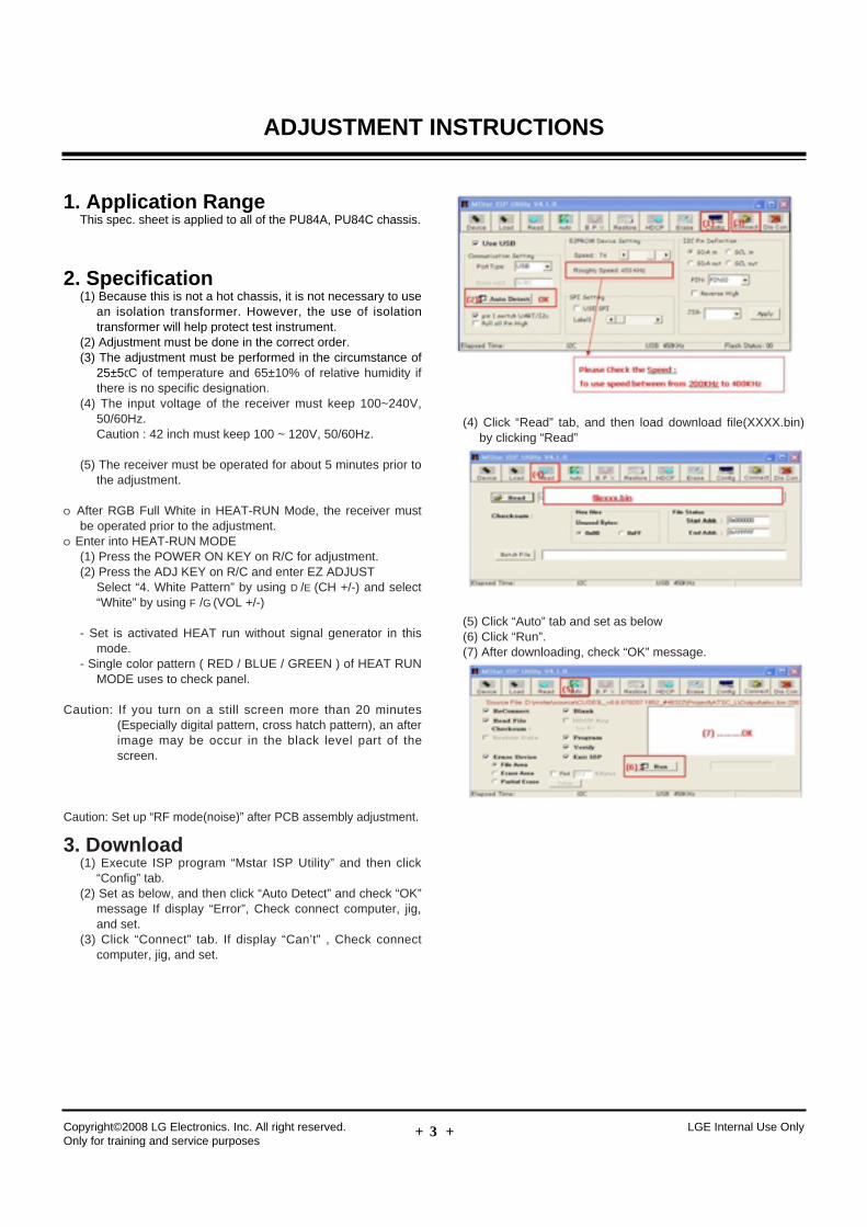
3. Download(1) Execute ISP program “Mstar ISP Utility” and then click
“Config” tab.(2) Set as below, and then click “Auto Detect” and check “OK”
message If display “Error”, Check connect computer, jig,and set.
(3) Click “Connect” tab. If display “Can’t” , Check connectcomputer, jig, and set.
(4) Click “Read” tab, and then load download file(XXXX.bin)by clicking “Read”
(5) Click “Auto” tab and set as below(6) Click “Run”.(7) After downloading, check “OK” message.
- 6 -
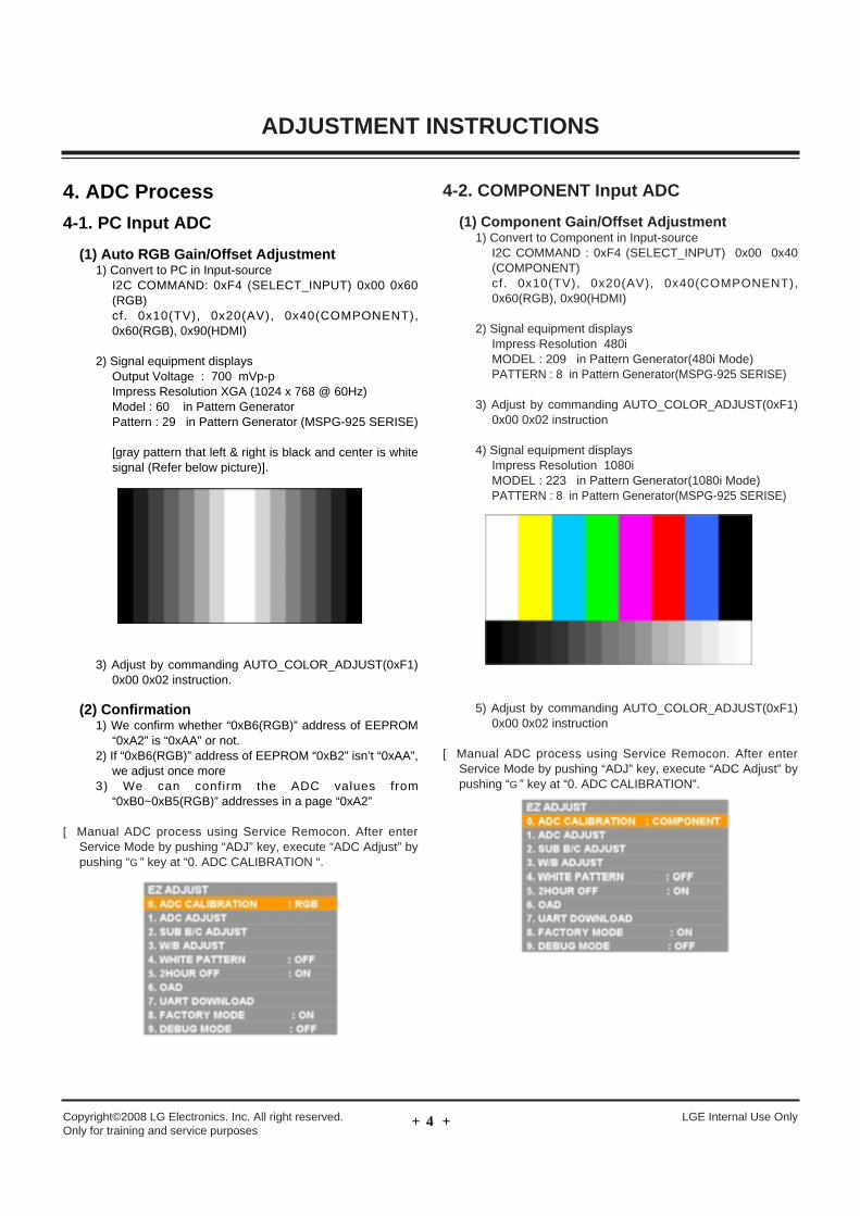
4. ADC Process
4-1. PC Input ADC
(1) Auto RGB Gain/Offset Adjustment1) Convert to PC in Input-source
I2C COMMAND: 0xF4 (SELECT_INPUT) 0x00 0x60(RGB)cf. 0x10(TV), 0x20(AV), 0x40(COMPONENT),0x60(RGB), 0x90(HDMI)
2) Signal equipment displaysOutput Voltage : 700 mVp-pImpress Resolution XGA (1024 x 768 @ 60Hz) Model : 60 in Pattern GeneratorPattern : 29 in Pattern Generator (MSPG-925 SERISE)
[gray pattern that left & right is black and center is whitesignal (Refer below picture)].
3) Adjust by commanding AUTO_COLOR_ADJUST(0xF1)0x00 0x02 instruction.
(2) Confirmation1) We confirm whether “0xB6(RGB)” address of EEPROM
“0xA2” is “0xAA” or not. 2) If “0xB6(RGB)” address of EEPROM “0xB2” isn’t “0xAA”,
we adjust once more3) We can confirm the ADC values from
“0xB0~0xB5(RGB)” addresses in a page “0xA2”
[ Manual ADC process using Service Remocon. After enterService Mode by pushing “ADJ” key, execute “ADC Adjust” bypushing “G” key at “0. ADC CALIBRATION “.
4-2. COMPONENT Input ADC
(1) Component Gain/Offset Adjustment1) Convert to Component in Input-source
I2C COMMAND : 0xF4 (SELECT_INPUT) 0x00 0x40(COMPONENT)cf. 0x10(TV), 0x20(AV), 0x40(COMPONENT),0x60(RGB), 0x90(HDMI)
2) Signal equipment displaysImpress Resolution 480iMODEL : 209 in Pattern Generator(480i Mode)PATTERN : 8 in Pattern Generator(MSPG-925 SERISE)
3) Adjust by commanding AUTO_COLOR_ADJUST(0xF1)0x00 0x02 instruction
4) Signal equipment displaysImpress Resolution 1080iMODEL : 223 in Pattern Generator(1080i Mode)PATTERN : 8 in Pattern Generator(MSPG-925 SERISE)
5) Adjust by commanding AUTO_COLOR_ADJUST(0xF1)0x00 0x02 instruction
[ Manual ADC process using Service Remocon. After enterService Mode by pushing “ADJ” key, execute “ADC Adjust” bypushing “G” key at “0. ADC CALIBRATION”.
Copyright©2008 LG Electronics. Inc. All right reserved. Only for training and service purposes
LGE Internal Use Only
ADJUSTMENT INSTRUCTIONS
- 7 -
4-3. Confirmation(1) We confirm whether “0xBF(480i)/0xC8(1080i)” address of
EEPROM “0xA2” is “0xAA” or not. (2) If “0xBF(480i)/0xC8(1080i)” address of EEPROM “0xA2”
isn’t “0xAA”, we adjust once more(3) We can confirm the ADC values from “0xB9 ~ 0xBE(480i) /
0xC2 ~ (1080i)” addresses in a page “0xA2”
[ Manual ADC Confirmation using Service Remocon. After enterService Mode by pushing “INSTART” key.
Caution: Each PCB assembly must be checked by check JIG set.(Because power PCB Assembly damages to PDPModule, especially be careful)
Caution: Set up “RF mode(noise)” before voltage adjustment.
5. POWER PCB Ass’y Voltage Adjustment (Va, Vs voltage Adjustment)
5-1. Test Equipment: D.M.M 1EA
5-2. Connection Diagram for MeasuringRefer to Fig.1, Fig 2, Fig 3
5-3. Adjustment Method
(1) 50” Va Adjustment (refer fig.1)1) After receiving 100% Full White Pattern, HEAT RUN.2) Connect + terminal of D.M.M. to Va pin of P802,
connect-terminal to GND pin of P802.3) After turning VR902,voltage of D.M.M adjustment as
same as Va voltage which on label of panel right/top(deviation; ±0.5V)
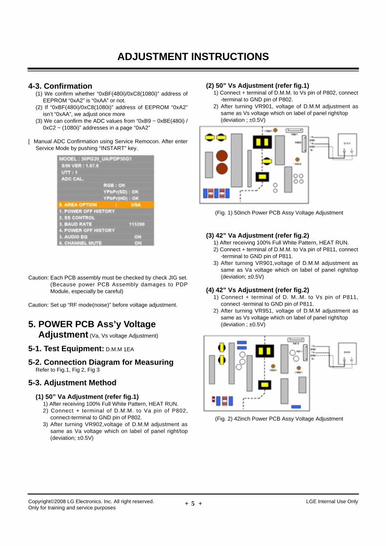
(2) 50” Vs Adjustment (refer fig.1)1) Connect + terminal of D.M.M. to Vs pin of P802, connect
-terminal to GND pin of P802.2) After turning VR901, voltage of D.M.M adjustment as
same as Vs voltage which on label of panel right/top(deviation ; ±0.5V)
(3) 42” Va Adjustment (refer fig.2) 1) After receiving 100% Full White Pattern, HEAT RUN.2) Connect + terminal of D.M.M. to Va pin of P811, connect
-terminal to GND pin of P811.3) After turning VR901,voltage of D.M.M adjustment as
same as Va voltage which on label of panel right/top(deviation; ±0.5V)
(4) 42” Vs Adjustment (refer fig.2)1) Connect + terminal of D. M..M. to Vs pin of P811,
connect -terminal to GND pin of P811.2) After turning VR951, voltage of D.M.M adjustment as
same as Vs voltage which on label of panel right/top(deviation ; ±0.5V)
Copyright©2008 LG Electronics. Inc. All right reserved. Only for training and service purposes
LGE Internal Use Only
ADJUSTMENT INSTRUCTIONS
(Fig. 1) 50inch Power PCB Assy Voltage Adjustment
(Fig. 2) 42inch Power PCB Assy Voltage Adjustment
- 8 -Copyright©2008 LG Electronics. Inc. All right reserved. Only for training and service purposes
LGE Internal Use Only
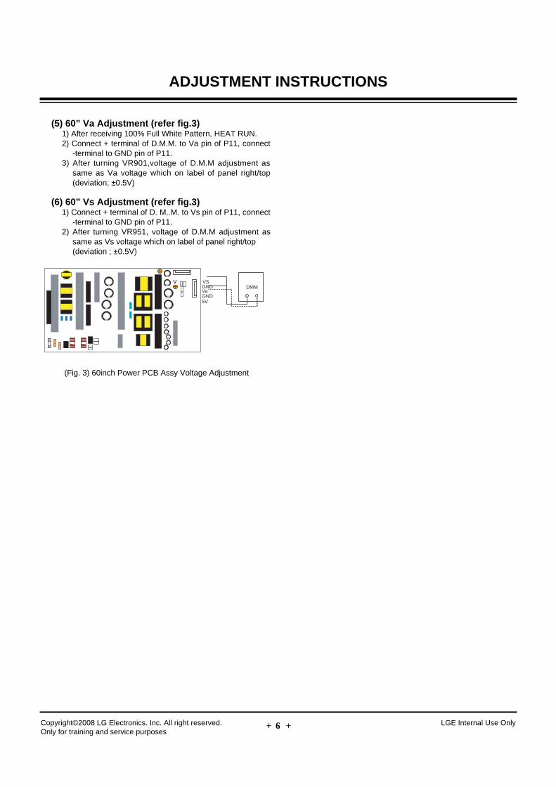
(5) 60” Va Adjustment (refer fig.3) 1) After receiving 100% Full White Pattern, HEAT RUN.2) Connect + terminal of D.M.M. to Va pin of P11, connect
-terminal to GND pin of P11.3) After turning VR901,voltage of D.M.M adjustment as
same as Va voltage which on label of panel right/top(deviation; ±0.5V)
(6) 60” Vs Adjustment (refer fig.3)1) Connect + terminal of D. M..M. to Vs pin of P11, connect
-terminal to GND pin of P11.2) After turning VR951, voltage of D.M.M adjustment as
same as Vs voltage which on label of panel right/top(deviation ; ±0.5V)
ADJUSTMENT INSTRUCTIONS
v VSGND
GND
DMMVa
5V
(Fig. 3) 60inch Power PCB Assy Voltage Adjustment
- 9 -
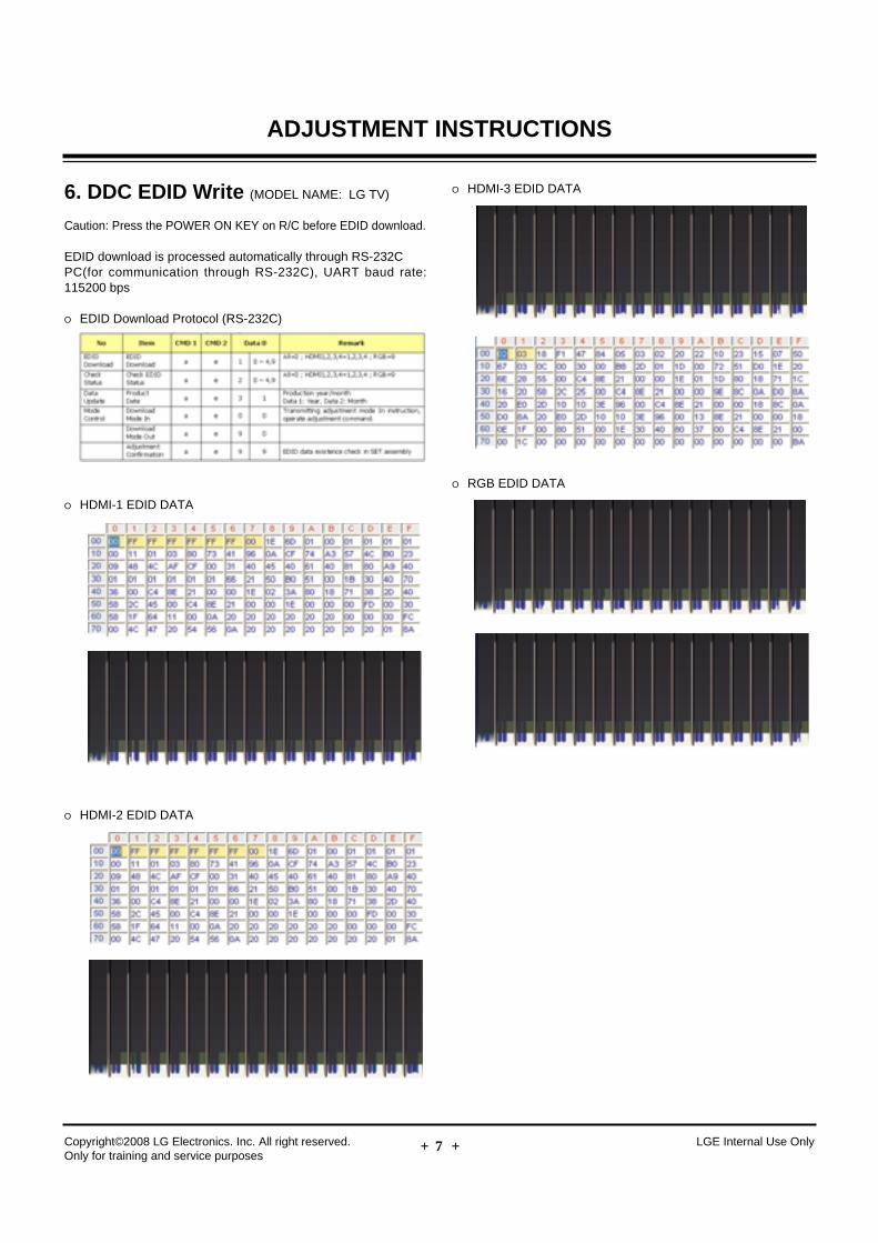
6. DDC EDID Write (MODEL NAME: LG TV)
Caution: Press the POWER ON KEY on R/C before EDID download.
EDID download is processed automatically through RS-232CPC(for communication through RS-232C), UART baud rate:115200 bps
O EDID Download Protocol (RS-232C)
O HDMI-1 EDID DATA
O HDMI-2 EDID DATA
O HDMI-3 EDID DATA
O RGB EDID DATA
Copyright©2008 LG Electronics. Inc. All right reserved. Only for training and service purposes
LGE Internal Use Only
ADJUSTMENT INSTRUCTIONS
- 10 -
7. Adjustment of White Balance
Caution: Press the POWER ON KEY on R/C before W/B adjustment.
7-1. Test Equipment- Color Analyzer (CS-1000, CA-100+(CH.10), CA-210(CH.10))
[ Please adjust CA-100+ / CA-210 by CS-1000 before measuring--> You should use Channel 10 which is Matrix compensated
(White, Red, Green, Blue revised) by CS-1000 and adjustin accordance with White balance adjustment coordinate.
O Color temperature standards according to CSM and Module
O Change target luminance and range of the Auto adjustmentW/B equipment.
O White balance adjustment coordinate and color temperature
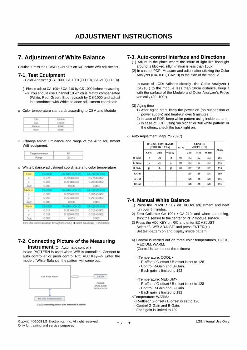
7-2. Connecting Picture of the Measuring Instrument (On Automatic control )
Inside PATTERN is used when W/B is controlled. Connect toauto controller or push control R/C ADJ Key—> Enter themode of White-Balance, the pattern will come out.
7-3. Auto-control Interface and Directions(1) Adjust in the place where the influx of light like floodlight
around is blocked. (illumination is less than 10ux).(2) In case of PDP: Measure and adjust after sticking the Color
Analyzer (CA-100+, CA210) to the side of the module.
In case of LCD: Adhere closely the Color Analyzer (CA210 ) to the module less than 10cm distance, keep itwith the surface of the Module and Color Analyzer’s Provevertically.(80~100°).
(3) Aging time 1) After aging start, keep the power on (no suspension of
power supply) and heat-run over 5 minutes.2) In case of PDP, keep white pattern using inside pattern.3) In case of LCD, using ’no signal’ or ‘full white pattern’ or
the others, check the back light on.
O Auto Adjustment Map(RS-232C)
7-4. Manual White Balance 1) Press the POWER KEY on R/C for adjustment and heat
run over 5 minutes.2) Zero Calibrate CA-100+ / CA-210, and when controlling,
stick the sensor to the center of PDP module surface.3) Press the ADJ KEY on R/C and enter EZ ASJUST
Select “3. W/B ADJUST” and press ENTER(A).Set test-pattern on and display inside pattern.
4) Control is carried out on three color temperatures, COOL,MEDIUM, WARM. (Control is carried out three times)
<Temperature: COOL>- R-offset / G-offset / B-offset is set to 128- Control R-Gain and G-Gain.- Each gain is limited to 192
<Temperature: MEDIUM>- R-offset / G-offset / B-offset is set to 128- Control R-Gain and G-Gain.- Each gain is limited to 192
<Temperature: WARM>- R-offset / G-offset / B-offset is set to 128- Control G-Gain and B-Gain.- Each gain is limited to 192
Copyright©2008 LG Electronics. Inc. All right reserved. Only for training and service purposes
LGE Internal Use Only
ADJUSTMENT INSTRUCTIONS
- 11 -
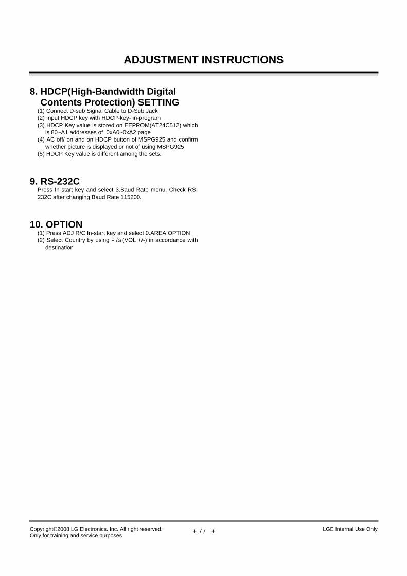
8. HDCP(High-Bandwidth DigitalContents Protection) SETTING
(1) Connect D-sub Signal Cable to D-Sub Jack(2) Input HDCP key with HDCP-key- in-program(3) HDCP Key value is stored on EEPROM(AT24C512) which
is 80~A1 addresses of 0xA0~0xA2 page(4) AC off/ on and on HDCP button of MSPG925 and confirm
whether picture is displayed or not of using MSPG925(5) HDCP Key value is different among the sets.
9. RS-232C Press In-start key and select 3.Baud Rate menu. Check RS-232C after changing Baud Rate 115200.
10. OPTION(1) Press ADJ R/C In-start key and select 0.AREA OPTION(2) Select Country by using F/G(VOL +/-) in accordance with
destination
Copyright©2008 LG Electronics. Inc. All right reserved. Only for training and service purposes
LGE Internal Use Only
ADJUSTMENT INSTRUCTIONS
- 12 -Copyright©2008 LG Electronics. Inc. All right reserved. Only for training and service purposes
LGE Internal Use Only
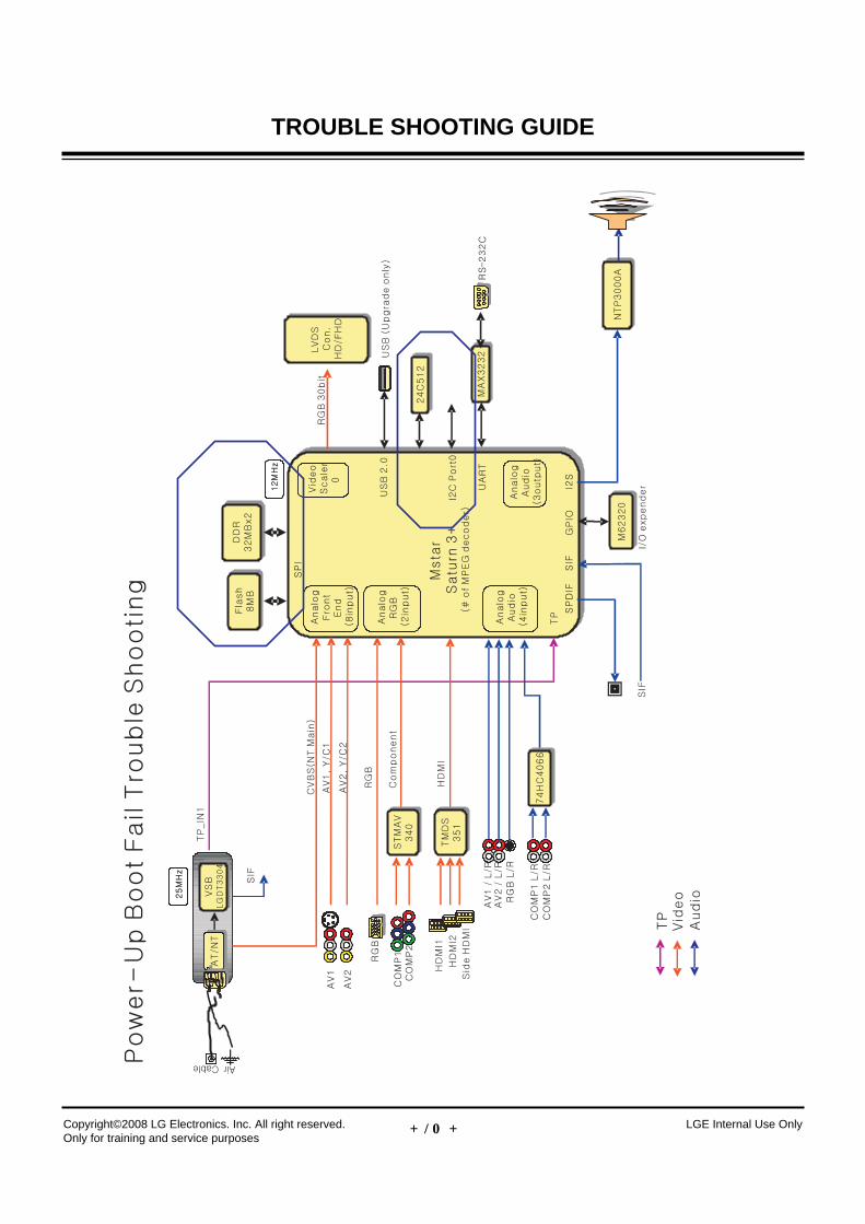
TROUBLE SHOOTING GUIDE
- 13 -Copyright©2008 LG Electronics. Inc. All right reserved. Only for training and service purposes
LGE Internal Use Only
TROUBLE SHOOTING GUIDE
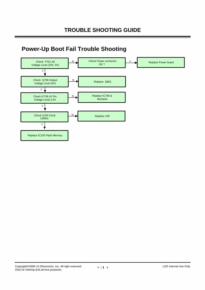
Power-Up Boot Fail Trouble Shooting
Check P701 AllVoltage Level (16V, 5V)
Check Power connectorOK ?
Replace Power board
Y
N Y
Check IC706 #2 PinVoltage Level 2.6V
Replace IC706 &Recheck
Y
N
Check X100 Clock12MHz
Replace 100
Y
N
Replace IC105 Flash Memory
Check Q706 OutputVoltage Level (5V)
Replace Q801N
Y
- 14 -Copyright©2008 LG Electronics. Inc. All right reserved. Only for training and service purposes
LGE Internal Use Only
TROUBLE SHOOTING GUIDE
- 15 -Copyright©2008 LG Electronics. Inc. All right reserved. Only for training and service purposes
LGE Internal Use Only
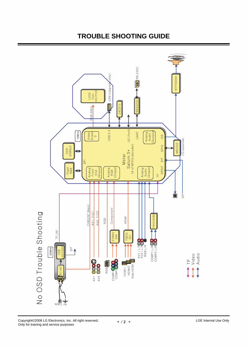
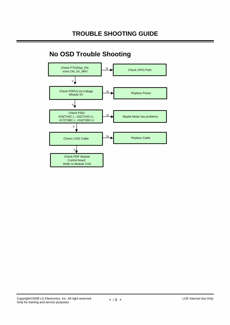
TROUBLE SHOOTING GUIDE
No OSD Trouble Shooting
Check P302#33(TXAC-) , #32(TXAC+) ,#17(TXBC-) , #16(TXBC+)
Maybe Mstar has problems
Check LVDS Cable
Check PDP ModuleControl board
Refer to Module CAS
Y
N
Y
Replace CableN
Y
Check PDP Vs,Va VoltageModule 5V Replace PowerN
Check P701 Disp_EN,VaVs ON, 5V_MNT Check GPIO PathN
Y
- 16 -Copyright©2008 LG Electronics. Inc. All right reserved. Only for training and service purposes
LGE Internal Use Only
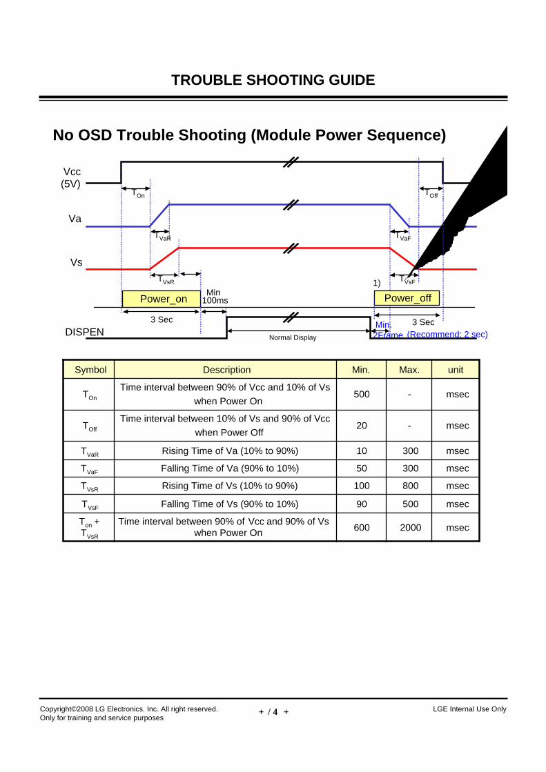
TROUBLE SHOOTING GUIDE
No OSD Trouble Shooting (Module Power Sequence)
Normal Display
Vcc(5V)
Va
Vs
DISPEN
TVaR
TVsR
TOn
TVaF
TVsF
TOff
1)
Power_on
3 Sec
Power_off
3 Sec
Min100ms
Min.2Frame (Recommend: 2 sec)
msec50090Falling Time of Vs (90% to 10%)TVsF
msec2000600Time interval between 90% of Vcc and 90% of Vs
when Power OnTon +TVsR
msec800100Rising Time of Vs (10% to 90%)TVsR
msec30050Falling Time of Va (90% to 10%)TVaF
msec30010Rising Time of Va (10% to 90%)TVaR
msec-20Time interval between 10% of Vs and 90% of Vcc
when Power OffTOff
msec-500Time interval between 90% of Vcc and 10% of Vs
when Power OnTOn
unitMax.Min.DescriptionSymbol
- 17 -Copyright©2008 LG Electronics. Inc. All right reserved. Only for training and service purposes
LGE Internal Use Only
TROUBLE SHOOTING GUIDE
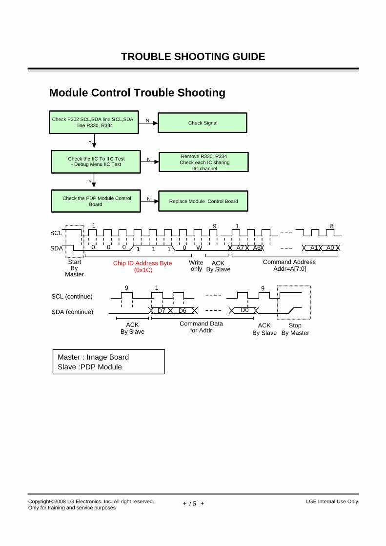
Module Control Trouble Shooting
Check the PDP Module ControlBoard
Replace Module Control BoardN
Y
Check the IIC To II C Test- Debug Menu IIC Test
Remove R330, R334Check each IC sharing
IIC channel
N
Check P302 SCL,SDA line SCL,SDAline R330, R334 Check SignalN
Y
SCL (continue)
SDA (continue)
ACKBy Slave
9 1
D0D7
9
ACKBy Slave
Command Datafor Addr
StopBy Master
D6
SCL8
SDA 0 0 1 1 1 A7W
StartBy
Master
Chip ID Address Byte(0x1C)
ACKBy Slave
0
1 9 1
A6 A1 A0
Command AddressAddr=A[7:0]
0
Writeonly
Master : Image BoardSlave : PDP Module
- 18 -Copyright©2008 LG Electronics. Inc. All right reserved. Only for training and service purposes
LGE Internal Use Only
TROUBLE SHOOTING GUIDE
- 19 -Copyright©2008 LG Electronics. Inc. All right reserved. Only for training and service purposes
LGE Internal Use Only
TROUBLE SHOOTING GUIDE
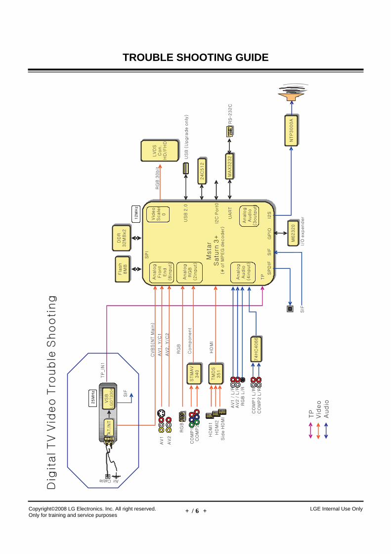
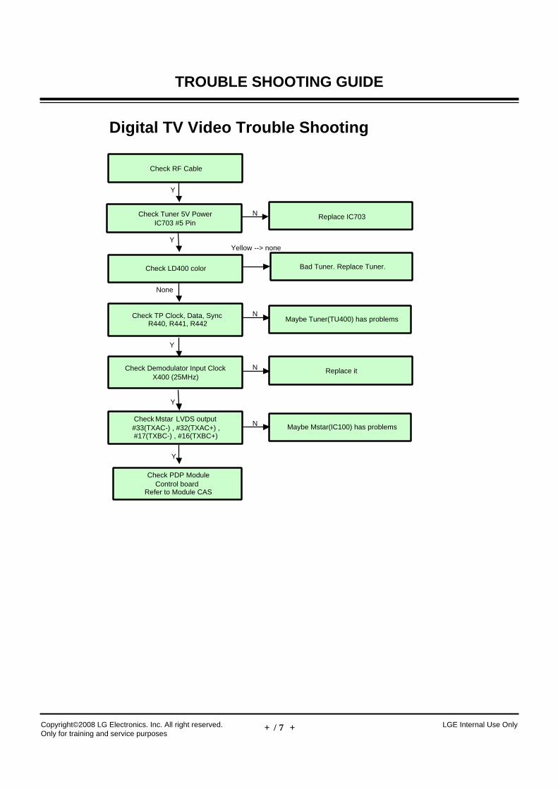
Digital TV Video Trouble Shooting
Check RF Cable
Check TP Clock, Data, SyncR440, R441, R442
Maybe Tuner(TU400) has problems
Check Mstar LVDS output#33(TXAC-) , #32(TXAC+) ,#17(TXBC-) , #16(TXBC+)
Y
N
Check Tuner 5V PowerIC703 #5 Pin
Replace IC703
Y
N
Y
Maybe Mstar(IC100) has problemsN
Y
Check LD400 color Bad Tuner. Replace Tuner.
None
Yellow --> none
Check Demodulator Input ClockX400 (25MHz)
Replace itN
Y
Check PDP ModuleControl board
Refer to Module CAS
- 20 -Copyright©2008 LG Electronics. Inc. All right reserved. Only for training and service purposes
LGE Internal Use Only
TROUBLE SHOOTING GUIDE
- 21 -Copyright©2008 LG Electronics. Inc. All right reserved. Only for training and service purposes
LGE Internal Use Only
TROUBLE SHOOTING GUIDE
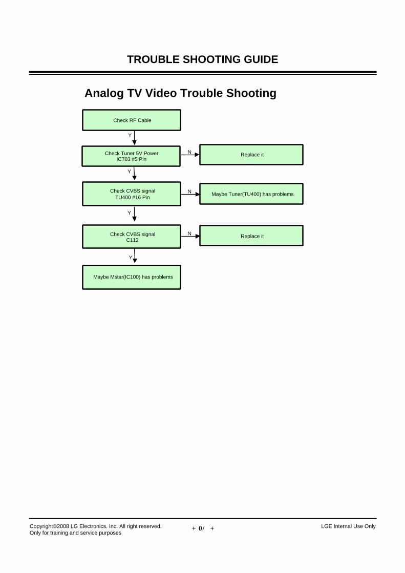
Analog TV Video Trouble Shooting
Check RF Cable
Check CVBS signalTU400 #16 Pin
Maybe Tuner(TU400) has problems
Check CVBS signalC112
Y
N
Check Tuner 5V PowerIC703 #5 Pin
Replace it
Y
N
Y
Replace itN
Y
Maybe Mstar(IC100) has problems

- 22 -Copyright©2008 LG Electronics. Inc. All right reserved. Only for training and service purposes
LGE Internal Use Only
TROUBLE SHOOTING GUIDE
- 23 -Copyright©2008 LG Electronics. Inc. All right reserved. Only for training and service purposes
LGE Internal Use Only
TROUBLE SHOOTING GUIDE
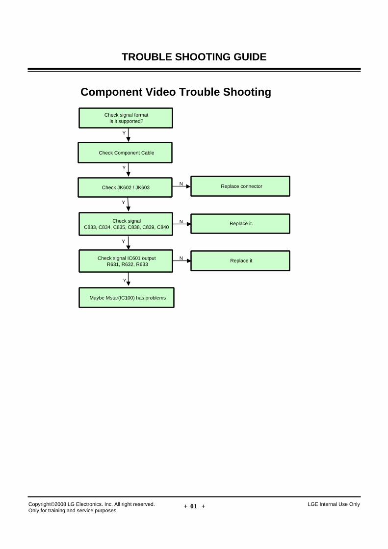
Component Video Trouble Shooting
Check signal formatIs it supported?
Check signalC833, C834, C835, C838, C839, C840
Replace it.
Check signal IC601 outputR631, R632, R633
Y
Y
N
Check JK602 / JK603 Replace connector
Y
N
Y
Replace itN
Maybe Mstar(IC100) has problems
Y
Check Component Cable
- 24 -Copyright©2008 LG Electronics. Inc. All right reserved. Only for training and service purposes
LGE Internal Use Only
TROUBLE SHOOTING GUIDE
- 25 -Copyright©2008 LG Electronics. Inc. All right reserved. Only for training and service purposes
LGE Internal Use Only
TROUBLE SHOOTING GUIDE
RGB Video Trouble Shooting
Check signal formatIs it supported?
Check signal, Hsync, VsyncR673, R674
Replace it.
Check signalR678, R679, R680
Y
Y
N
Check JK607 Replace connector
Y
N
Y
Replace it.N
Maybe Mstar(IC100) has problems
Y
Check SignalC116, C124, C126
Replace itN
Check RGB Cable
Y
- 26 -Copyright©2008 LG Electronics. Inc. All right reserved. Only for training and service purposes
LGE Internal Use Only
TROUBLE SHOOTING GUIDE
- 27 -Copyright©2008 LG Electronics. Inc. All right reserved. Only for training and service purposes
LGE Internal Use Only
TROUBLE SHOOTING GUIDE
AV Video Trouble Shooting
Check signal formatIs it supported?
Check signalC948 (Composite), C991 / C992 (S-Video) (Rear)
C949 (Composite)Replace it.
Check signalC111 (Composite), C109 / C110 (S-Video) (Rear)
C174 (Composite) (Side)
Y
N
Check JK601 (Rear)Check JK604 (Side)
Replace connector
Y
N
Y
Replace itN
Maybe Mstar(IC100) has problems
Y
Check AV Cable / S-Video Cable
Y
- 28 -Copyright©2008 LG Electronics. Inc. All right reserved. Only for training and service purposes
LGE Internal Use Only
TROUBLE SHOOTING GUIDE
- 29 -Copyright©2008 LG Electronics. Inc. All right reserved. Only for training and service purposes
LGE Internal Use Only
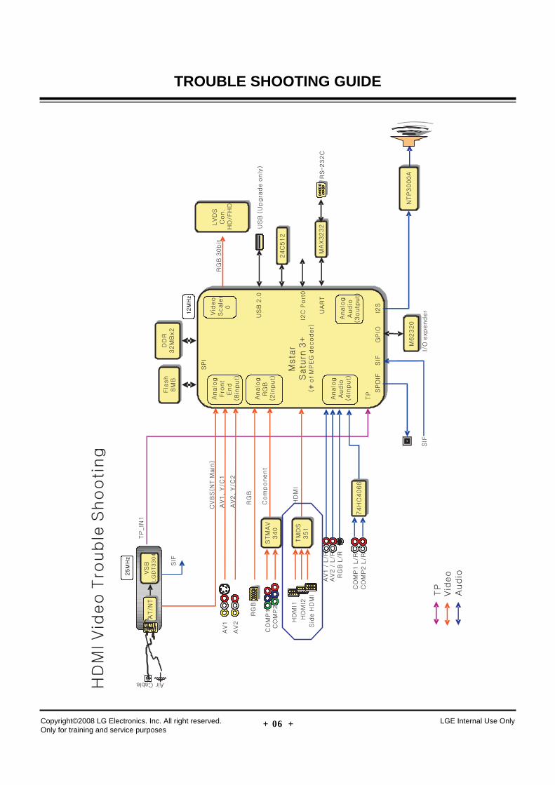
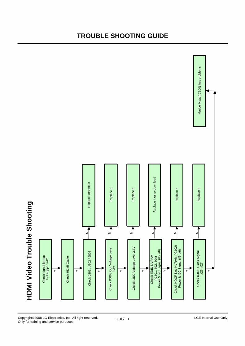
TROUBLE SHOOTING GUIDEH
DM
I Vid
eo T
rou
ble
Sh
oo
tin
g
Che
ck s
igna
l for
mat
Is it
sup
port
ed?
Y
Che
ck J
801
/ J80
2 / J
803
Rep
lace
con
nect
or
Y
N
Y
Che
ck H
DM
I Cab
le
Che
ck E
DID
NV
RA
M(I
C80
1, 8
02, 8
04)
Pow
er &
I2C
Sig
nal (
#5, #
6)
Rep
lace
it o
r re
-dow
nloa
d
Y
N
Che
ck H
DC
P K
ey N
VR
AM
(IC
102)
Pow
er &
I2C
Sig
nal (
#5, #
6)R
epla
ce it
Y
N
Che
ck IC
803
Out
Vol
tage
Lev
el3.
3VR
epla
ce it
Y
N
Che
ck L
802
Vol
tage
Lev
el 3
.3V
Rep
lace
it
Y
N
Che
ck IC
803
Clo
ck S
igna
l#2
6, #
27R
epla
ce it
Y
NM
aybe
Mst
ar(I
C10
0) h
as p
robl
ems
- 30 -Copyright©2008 LG Electronics. Inc. All right reserved. Only for training and service purposes
LGE Internal Use Only
TROUBLE SHOOTING GUIDE
- 31 -Copyright©2008 LG Electronics. Inc. All right reserved. Only for training and service purposes
LGE Internal Use Only
TROUBLE SHOOTING GUIDE
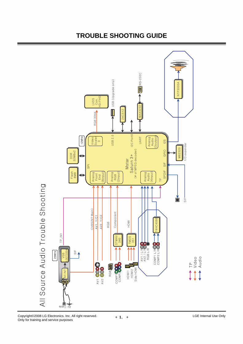
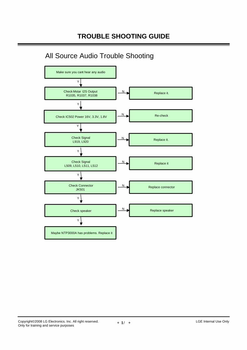
All Source Audio Trouble Shooting
Make sure you cant hear any audio
Check SignalL919, L920
Replace it.
Check SignalL509, L510, L511, L512
Y
N
Check IC502 Power 16V, 3.3V, 1.8V Re-check
Y
N
Y
Replace itN
Check ConnectorJK501
Y
Check Mstar I2S OutputR1035, R1037, R1038
Y
Replace it.N
Replace connectorN
Check speaker
Y
Replace speakerN
Maybe NTP3000A has problems. Replace it
Y
- 32 -Copyright©2008 LG Electronics. Inc. All right reserved. Only for training and service purposes
LGE Internal Use Only
TROUBLE SHOOTING GUIDE
- 33 -Copyright©2008 LG Electronics. Inc. All right reserved. Only for training and service purposes
LGE Internal Use Only
TROUBLE SHOOTING GUIDE
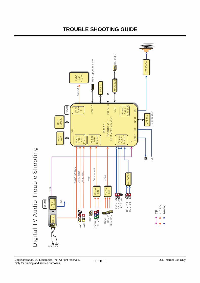
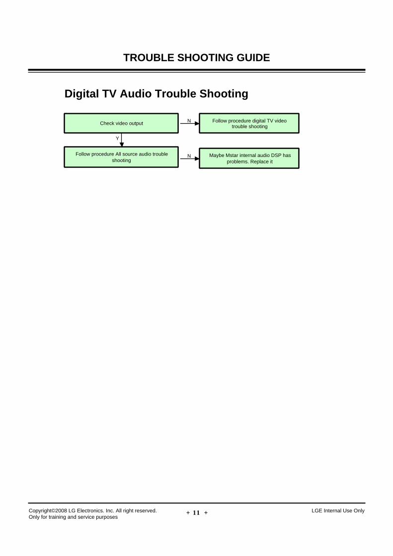
Digital TV Audio Trouble Shooting
Check video output
Follow procedure All source audio troubleshooting
Y
Follow procedure digital TV videotrouble shooting
N
N Maybe Mstar internal audio DSP hasproblems. Replace it
- 34 -Copyright©2008 LG Electronics. Inc. All right reserved. Only for training and service purposes
LGE Internal Use Only
TROUBLE SHOOTING GUIDE
- 35 -Copyright©2008 LG Electronics. Inc. All right reserved. Only for training and service purposes
LGE Internal Use Only
TROUBLE SHOOTING GUIDE
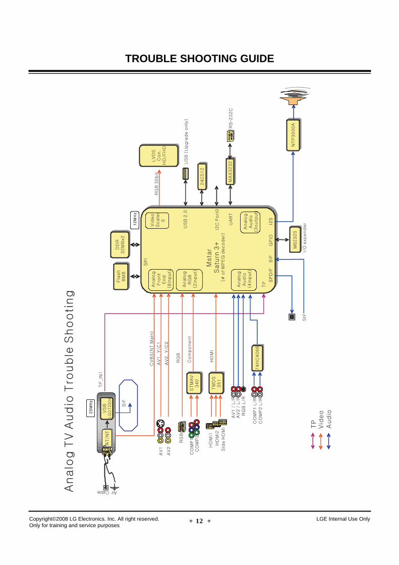
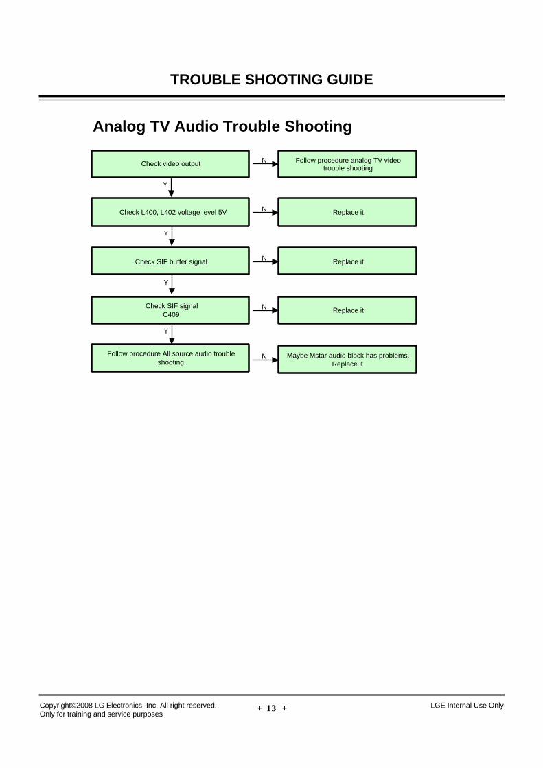
Analog TV Audio Trouble Shooting
Check video output
Follow procedure All source audio troubleshooting
Y
Follow procedure analog TV videotrouble shooting
N
N Maybe Mstar audio block has problems.Replace it
Check L400, L402 voltage level 5V Replace itN
Y
Check SIF buffer signal Replace itN
Y
Check SIF signalC409
Replace itN
Y
- 36 -Copyright©2008 LG Electronics. Inc. All right reserved. Only for training and service purposes
LGE Internal Use Only
TROUBLE SHOOTING GUIDE
- 37 -Copyright©2008 LG Electronics. Inc. All right reserved. Only for training and service purposes
LGE Internal Use Only
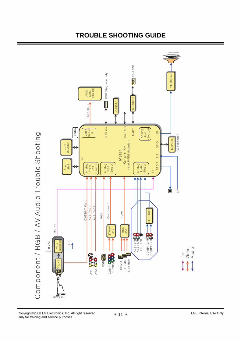
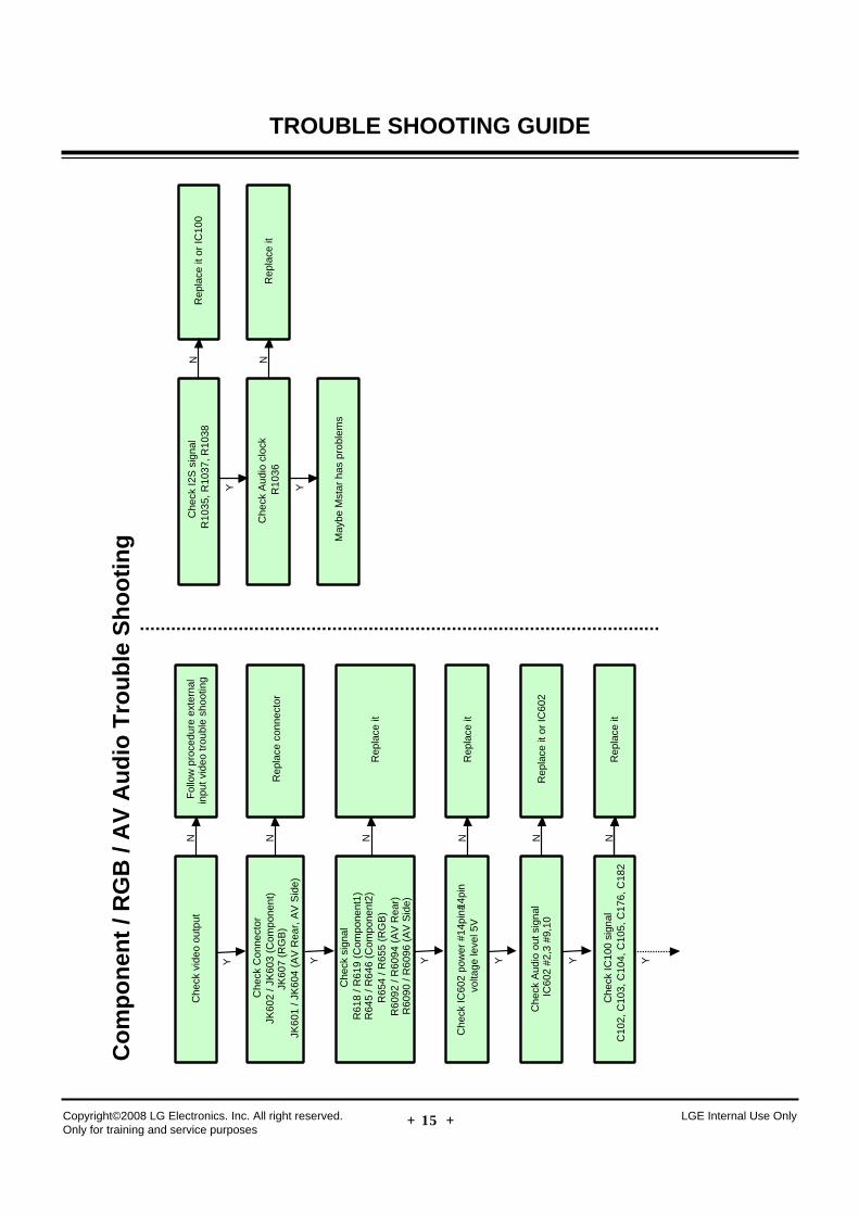
TROUBLE SHOOTING GUIDEC
om
po
nen
t / R
GB
/ A
V A
ud
io T
rou
ble
Sh
oo
tin
g
Che
ck v
ideo
out
put
Y
Fol
low
pro
cedu
re e
xter
nal
inpu
t vid
eo tr
oubl
e sh
ootin
gN
Che
ck C
onne
ctor
JK60
2 / J
K60
3 (C
ompo
nent
)JK
607
(RG
B)
JK60
1 / J
K60
4 (A
V R
ear,
AV
Sid
e)
Rep
lace
con
nect
orN
Y
Che
ck s
igna
lR
618
/ R61
9 (C
ompo
nent
1)R
645
/ R64
6 (C
ompo
nent
2)R
654
/ R65
5 (R
GB
)R
6092
/ R
6094
(A
V R
ear)
R60
90 /
R60
96 (
AV
Sid
e)
Rep
lace
itN
Y
Che
ck IC
602
pow
er #
14pi
n#14
pin
vol
tage
leve
l 5V
Rep
lace
itN
Y
Che
ck A
udio
out
sig
nal
IC60
2 #2
,3 #
9,10
Rep
lace
it o
r IC
602
N
Y
Che
ck IC
100
sign
alC
102,
C10
3, C
104,
C10
5, C
176,
C18
2R
epla
ce it
N
Y
Che
ck I2
S s
igna
lR
1035
, R10
37, R
1038
Rep
lace
it o
r IC
100
N
Y
Che
ck A
udio
clo
ckR
1036
Rep
lace
itN
Y
May
be M
star
has
pro
blem
s
- 38 -Copyright©2008 LG Electronics. Inc. All right reserved. Only for training and service purposes
LGE Internal Use Only
TROUBLE SHOOTING GUIDE
- 39 -Copyright©2008 LG Electronics. Inc. All right reserved. Only for training and service purposes
LGE Internal Use Only
TROUBLE SHOOTING GUIDE
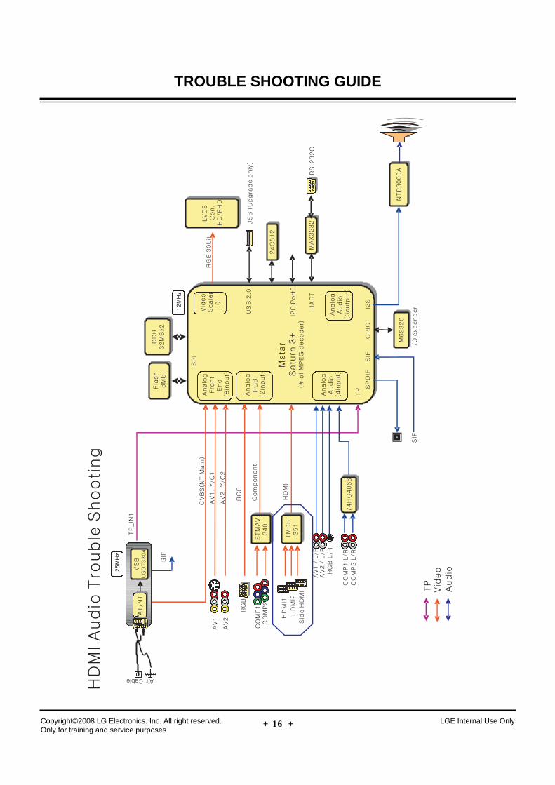
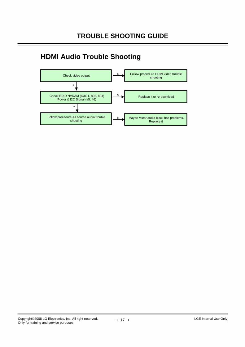
HDMI Audio Trouble Shooting
Check video output
Follow procedure All source audio troubleshooting
Y
Follow procedure HDMI video troubleshooting
N
N Maybe Mstar audio block has problems.Replace it
Check EDID NVRAM (IC801, 802, 804)Power & I2C Signal (#5, #6)
Replace it or re-download
Y
N
- 40 -Copyright©2008 LG Electronics. Inc. All right reserved. Only for training and service purposes
LGE Internal Use Only
TROUBLE SHOOTING GUIDE
- 41 -Copyright©2008 LG Electronics. Inc. All right reserved. Only for training and service purposes
LGE Internal Use Only
TROUBLE SHOOTING GUIDE
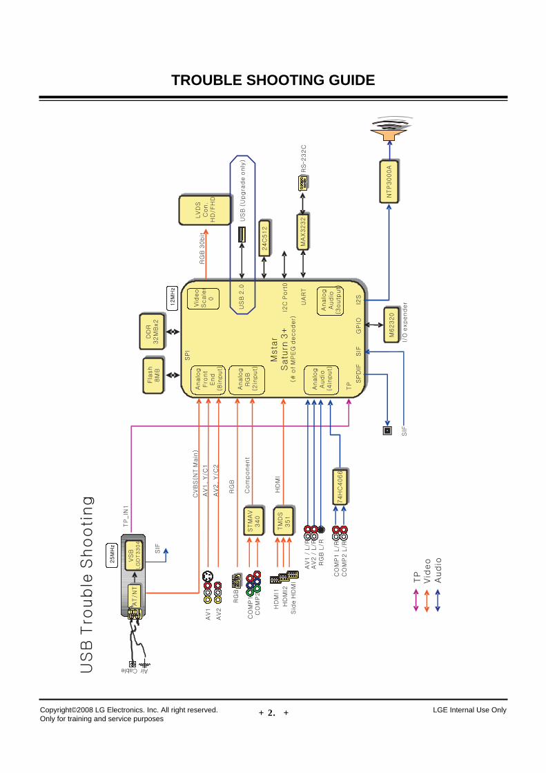
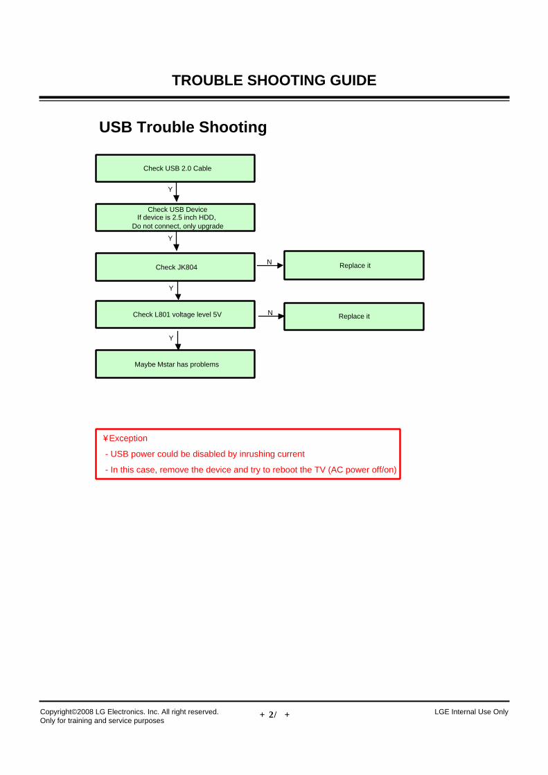
USB Trouble Shooting
Check USB 2.0 Cable
Check L801 voltage level 5V
Y
N Replace it
Check JK804 Replace it
Y
N
Check USB DeviceIf device is 2.5 inch HDD,
Do not connect, only upgrade
Y
Maybe Mstar has problems
Y
¥ Exception
- USB power could be disabled by inrushing current
- In this case, remove the device and try to reboot the TV (AC power off/on)
- 42 -Copyright©2008 LG Electronics. Inc. All right reserved. Only for training and service purposes
LGE Internal Use Only
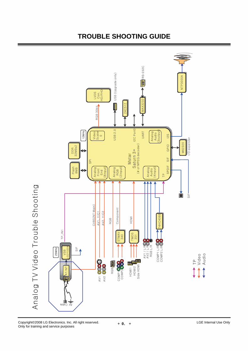
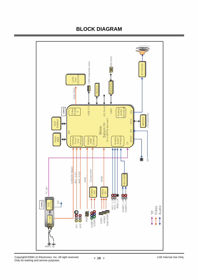
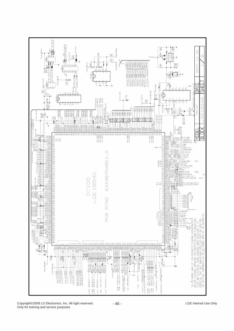
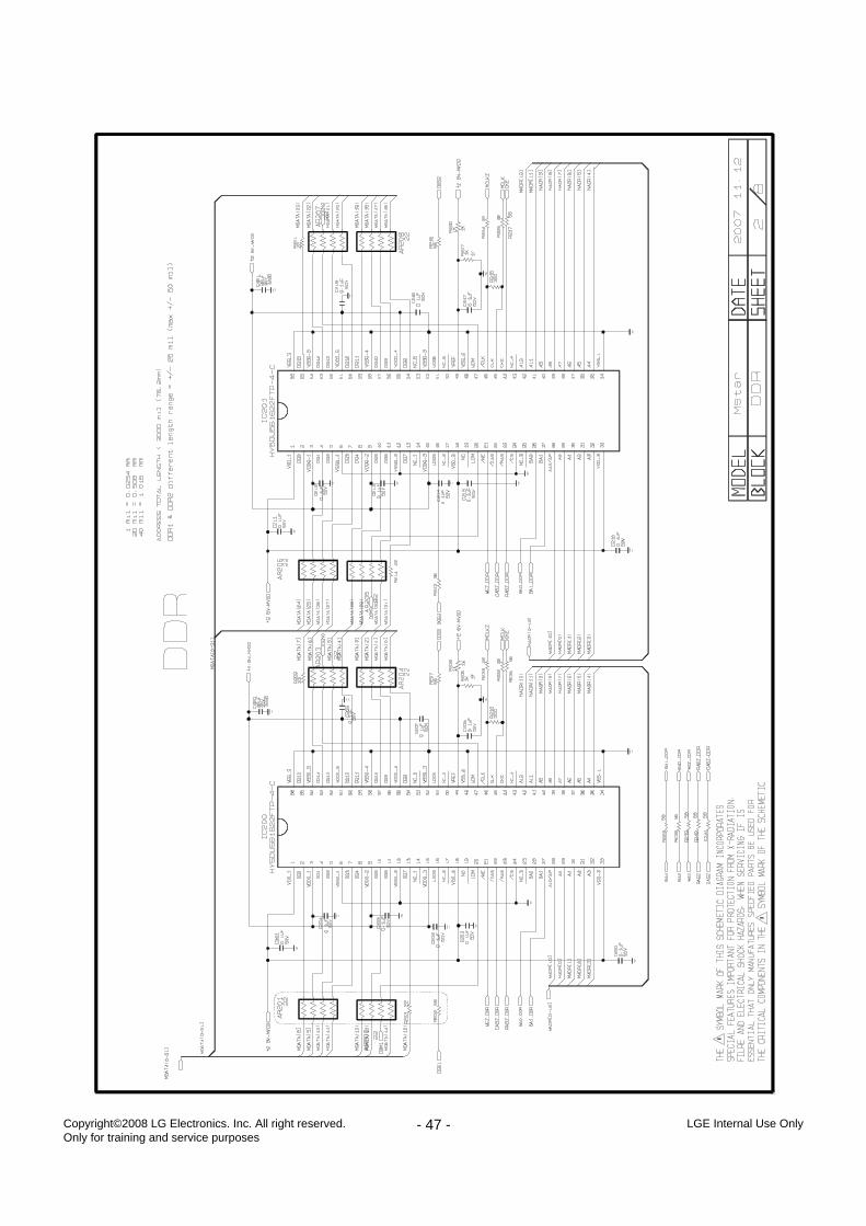
BLOCK DIAGRAM
- 43 -Copyright©2008 LG Electronics. Inc. All right reserved. Only for training and service purposes
LGE Internal Use Only
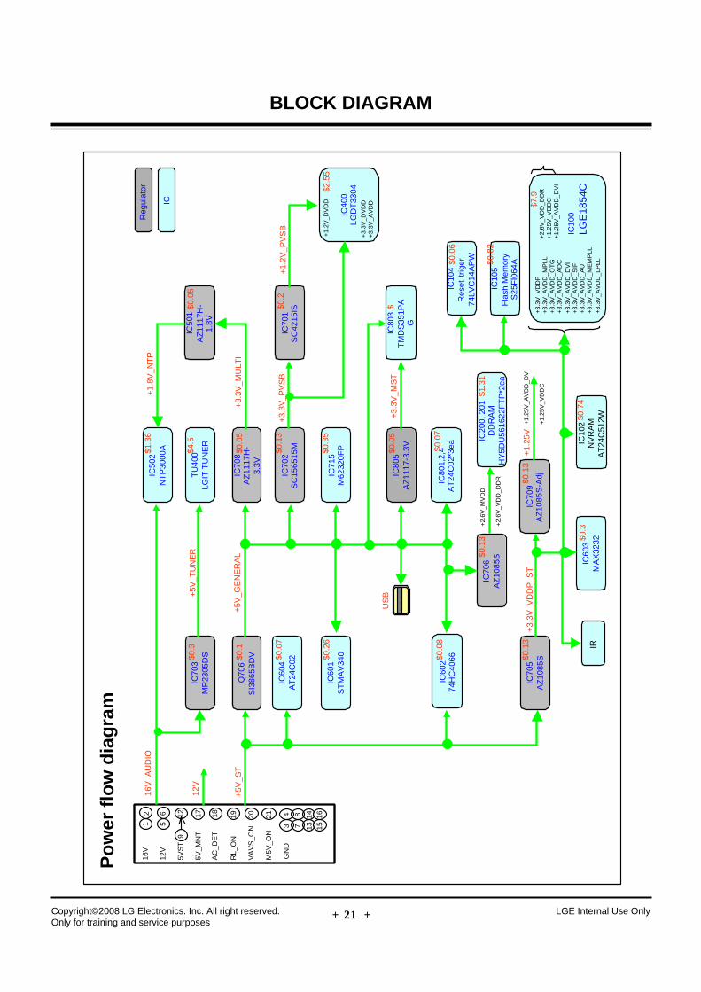
BLOCK DIAGRAMP
ow
er f
low
dia
gra
m
IC
100
L
GE
1854
C
+3.
3V_V
DD
P+
3.3V
_AV
DD
_MP
LL+
3.3V
_AV
DD
_OT
G+
3.3V
_AV
DD
_AD
C+
3.3V
_AV
DD
_DV
I+
3.3V
_AV
DD
_SIF
+3.
3V_A
VD
D_A
U+
3.3V
_AV
DD
_ME
MP
LL+
3.3V
_AV
DD
_LP
LL
TU
400
LGIT
TU
NE
R
IC10
5F
lash
Mem
ory
S25
Fl0
64A
IC20
0, 2
01D
DR
AM
HY
5DU
5616
22F
TP
*2ea
IRIC
102
NV
RA
MA
T24
C51
2W
Reg
ulat
or
IC
16V
_AU
DIO
IC70
3M
P23
05D
S
+5V
_TU
NE
R12
V
Q70
6S
I386
5BD
V
+5V
_GE
NE
RA
L+
5V_S
TIC
708
AZ
1117
H-
3.3V
+3.
3V_M
ULT
I
IC70
6A
Z10
85S
+2.
6V_M
VD
D
+2.
6V_V
DD
_DD
R
IC70
5A
Z10
85S
+3.
3V_V
DD
P_S
TIC
709
AZ
1085
S-A
dj
+1.
25V
IC70
2S
C15
6515
M
+3.
3V_P
VS
BIC
701
SC
4215
IS+
1.2V
_PV
SB
IC71
5M
6232
0FP
IC80
5A
Z11
17-3
.3V
IC80
3T
MD
S35
1PA
G
+3.
3V_M
ST
IC80
1,2,
4A
T24
C02
*3ea
IC60
1S
TM
AV
340
IC60
274
HC
4066
IC60
3M
AX
3232
IC60
4A
T24
C02
IC50
2N
TP
3000
A
IC50
1A
Z11
17H
-1.
8V
+1.
8V_N
TP
+1.
25V
_AV
DD
_DV
I
+1.
25V
_VD
DC
IC10
4R
eset
trig
er74
LVC
14A
PW
12 17
56 19 20
9
4 812
16V
12V
5VS
T
AC
_DE
T
VA
VS
_ON
M5V
_ON
GN
D
5V_M
NT
RL_
ON
18 21
3 7
14 1613 15
+2.
6V_V
DD
_DD
R+
1.25
V_V
DD
C+
1.25
V_A
VD
D_D
VI
$0.3
$0.1
$0.3
$0.0
7
$0.2
6
$0.0
8
$0.1
3
$0.1
3
$1.3
6
$4.5
$0.0
5
$0.1
3
$0.3
5
$0.0
5
$0.0
7
$1.3
1
$0.1
3
$0.0
6
$0.8
2
$7.9
$
IC40
0LG
DT
3304
+3.
3V_D
VD
D+
3.3V
_AV
DD
+1.
2V_D
VD
D$2
.55
$0.2
$0.0
5
$0.7
4
US
B
- 44 -Copyright©2008 LG Electronics. Inc. All right reserved. Only for training and service purposes
LGE Internal Use Only
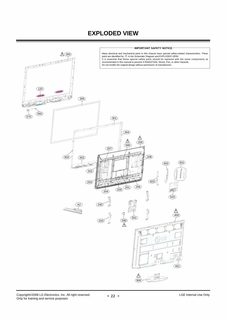
EXPLODED VIEW
300
120
305
301
302
200
201204
590501
205206
202
203
240
250
303
304
208
603
520
400
401
602 601
580207
570560
A2
900
Many electrical and mechanical parts in this chassis have special safety-related characteristics. Theseparts are identified by in the Schematic Diagram and EXPLODED VIEW. It is essential that these special safety parts should be replaced with the same components asrecommended in this manual to prevent X-RADIATION, Shock, Fire, or other Hazards. Do not modify the original design without permission of manufacturer.
IMPORTANT SAFETY NOTICE
- 45 -Copyright©2008 LG Electronics. Inc. All right reserved. Only for training and service purposes
LGE Internal Use Only
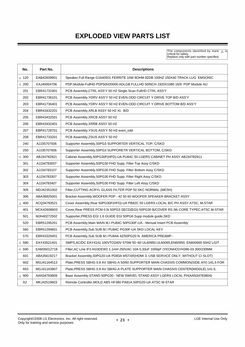
EXPLODED VIEW PARTS LIST
120 EAB42609901 Speaker,Full Range G1640501 FERRITE 10W 8OHM 82DB 100HZ 150X40 TRACK LUG EMSONIC
200 EAJ40004706 PDP,Module-FullHD PDP50H20000.ADLGB FULLHD 50INCH 1920X1080 16/9 PDP Module AU
201 EBR41731901 PCB Assembly,CTRL ASS’Y 50 H2 Single Scan FullHD CTRL ASS’Y
202 EBR41736101 PCB Assembly,YDRV ASS’Y 50 H2 EVEN-ODD CIRCUIT Y DRIVE TOP B/D ASS’Y
203 EBR41736401 PCB Assembly,YDRV ASS’Y 50 H2 EVEN-ODD CIRCUIT Y DRIVE BOTTOM B/D ASS’Y
204 EBR43432201 PCB Assembly,XRLB ASSY 50 H2 XL B/D
205 EBR43432501 PCB Assembly,XRCB ASSY 50 H2
206 EBR43432401 PCB Assembly,XRRB ASSY 50 H2
207 EBR41728701 PCB Assembly,YSUS ASS’Y 50 H2 even_odd
208 EBR41733201 PCB Assembly,ZSUS ASS’Y 50 H2
240 AJJ35707506 Supporter Assembly,50PG3 SUPPORTER VERTICAL TOP, C/SKD
250 AJJ35707606 Supporter Assembly,50PG3 SUPPORETR VERTICAL BOTTOM, C/SKD
300 ABJ34782921 Cabinet Assembly,50PG30F(HFD)-UA PU84C 50 LGERS CABINET PH ASSY ABJ34782911
301 AJJ34783007 Supporter Assembly,50PG30 FHD Supp. Filter Top Assy C/SKD
302 AJJ34783107 Supporter Assembly,50PG30 FHD Supp. Filter Bottom Assy C/SKD
303 AJJ34783307 Supporter Assembly,50PG30 FHD Supp. Filter Right Assy C/SKD
304 AJJ34783407 Supporter Assembly,50PG30 FHD Supp. Filter Left Assy C/SKD
305 MDJ42351002 Filter,CUTTING ACRYL GLASS FILTER PDP 50 SKC NORMAL (MESH)
306 ABA36825001 Bracket Assembly,WOOFER PDP - 42 50 60 WOOFER SPEAKER BRACKET ASSY
400 ACQ34783521 Cover Assembly,Rear 50PG30F(HFD)-UA PB82C 50 LGERS LOCAL B/C PH ASSY ATSC, M-STAR
401 MCK42608603 Cover,Rear PRESS PCM 0.5t 50PG3 SECD(EGI) 50PG30 B/COVER RS 3th CORE TYPEC:ATSC M-STAR
501 MJH40272502 Supporter,PRESS EGI 1.6 GUIDE EGI 50PG6 Supp module guide,SKD
520 EBR51295201 PCB Assembly,Main MAIN M.I PU84C 50PG30F-UA - Menual Insert PCB Assembly
560 EBR51294601 PCB Assembly,Sub SUB M.I PU84C PG30F-UA SKD LOCAL KEY
570 EBR43329401 PCB Assembly,Sub SUB M.I PU84A 42/50PG20 N. AMERICA PREAMP -
580 EAY43521401 SMPS,AC/DC EAY4141 100VTO240V 570W 50~60 UL60950,UL60065,EN60950, EN600665 50H2 LGIT
590 EAM35012718 Filter,AC Line IF2-N10DEW2 1.1mH 250VAC 10A 0.33uF 1000pF (YEONHO)YH396-03 300/230MM
601 ABA35619217 Bracket Assembly,50PG20-UA PD83A MSTAR(HDMI 3, USB SERVICE ONLY, WITHOUT CI SLOT)
602 MGJ41164513 Plate,PRESS SBHG 0.8 AV SBHG-A 50/60 SUPPORTER MAIN CHASSIS COMMON(SIDE A/V) 141.5 FOR
603 MGJ41163807 Plate,PRESS SBHG 0.8 AV SBHG-A PLATE SUPPORTER MAIN CHASSIS CENTER(MIDDLE) 141.5,
900 AAN34783809 Base Assembly,STAND 50PG30 - NEW SWIVEL STAND ASSY LGERS LOCAL PH(AAN34783804)
A2 MKJ42519603 Remote Controller,MOLD ABS HF380 PA81A 50PG20-UA ATSC M-STAR
No. Part No. Descriptions
The components identified by mark iscritical for safety.Replace only with part number specified.
- 46 - LGE Internal Use OnlyCopyright©2008 LG Electronics. Inc. All right reserved. Only for training and service purposes
- 47 - LGE Internal Use OnlyCopyright©2008 LG Electronics. Inc. All right reserved. Only for training and service purposes
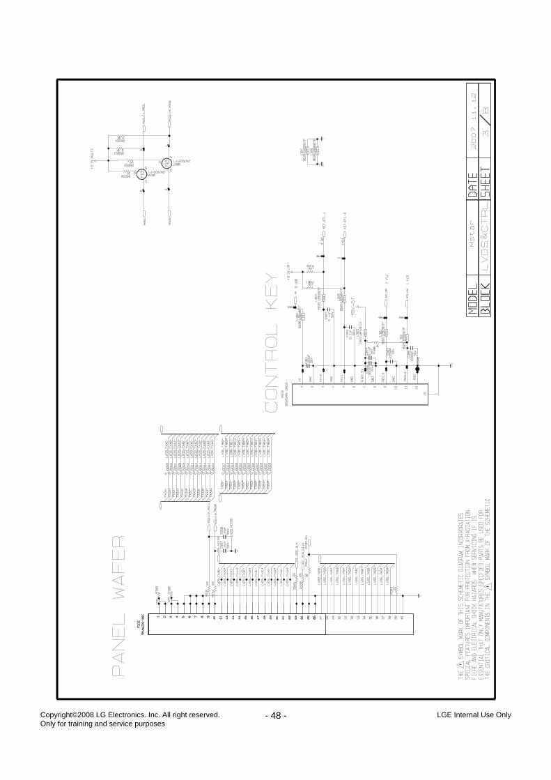
- 48 - LGE Internal Use OnlyCopyright©2008 LG Electronics. Inc. All right reserved. Only for training and service purposes
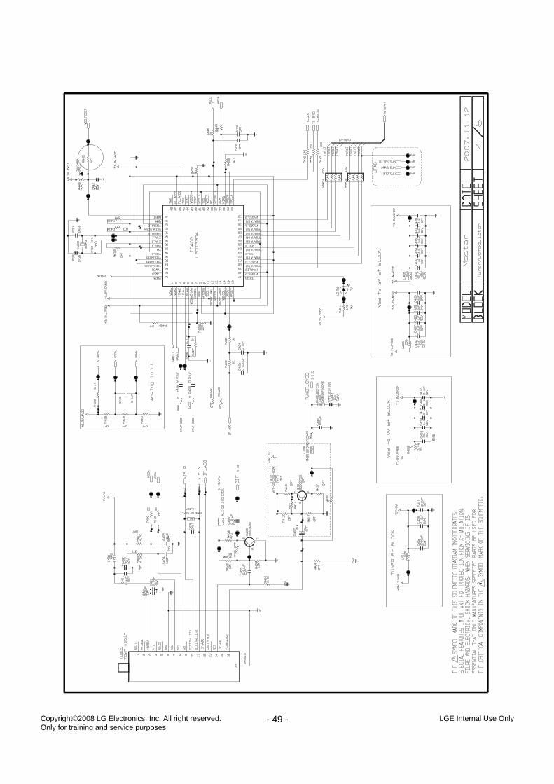
- 49 - LGE Internal Use OnlyCopyright©2008 LG Electronics. Inc. All right reserved. Only for training and service purposes
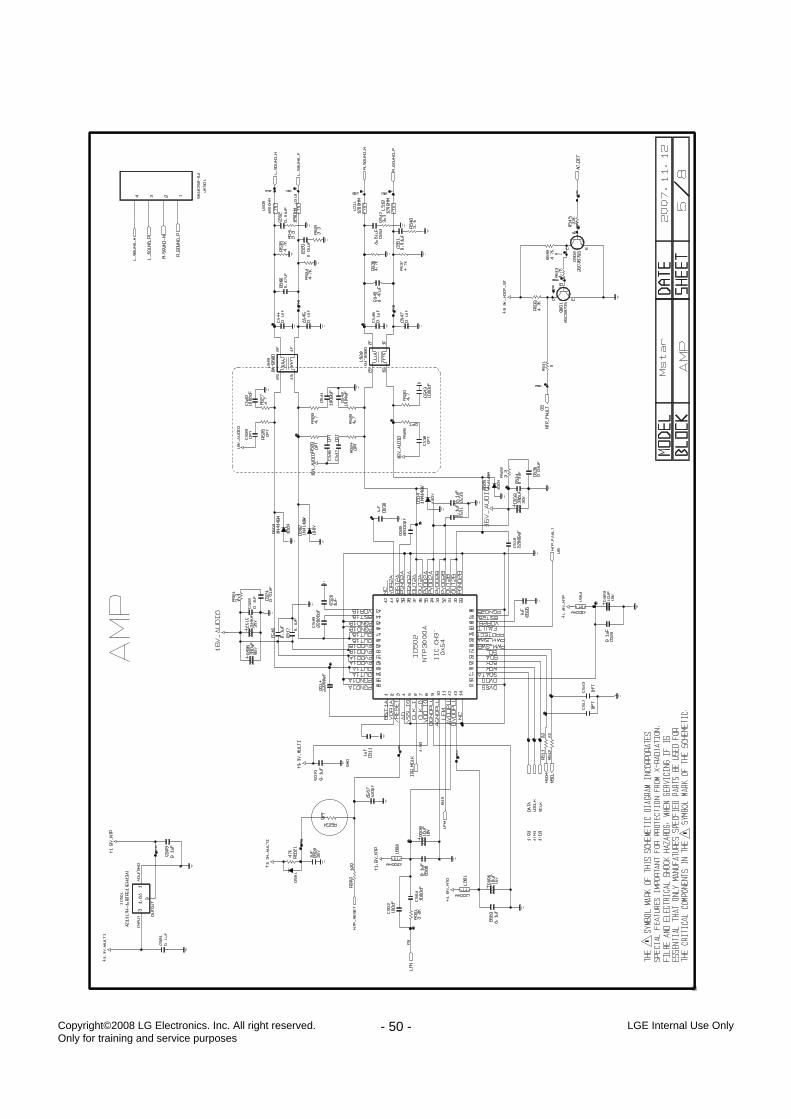
- 50 - LGE Internal Use OnlyCopyright©2008 LG Electronics. Inc. All right reserved. Only for training and service purposes
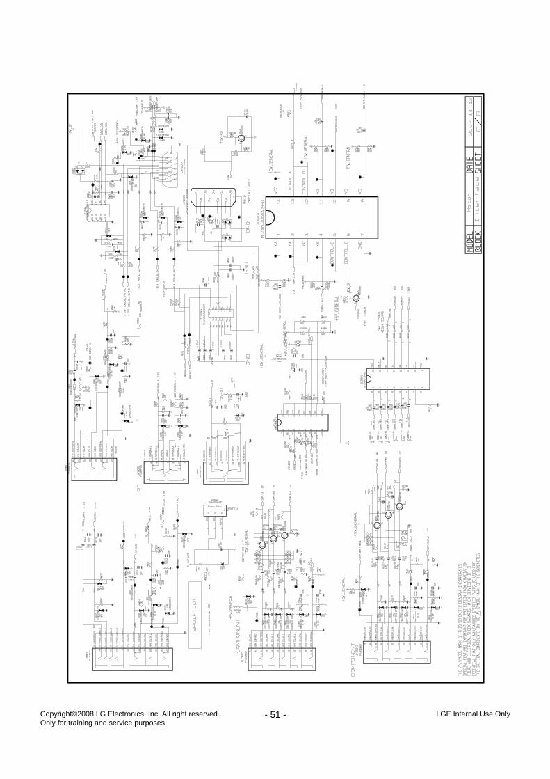
- 51 - LGE Internal Use OnlyCopyright©2008 LG Electronics. Inc. All right reserved. Only for training and service purposes
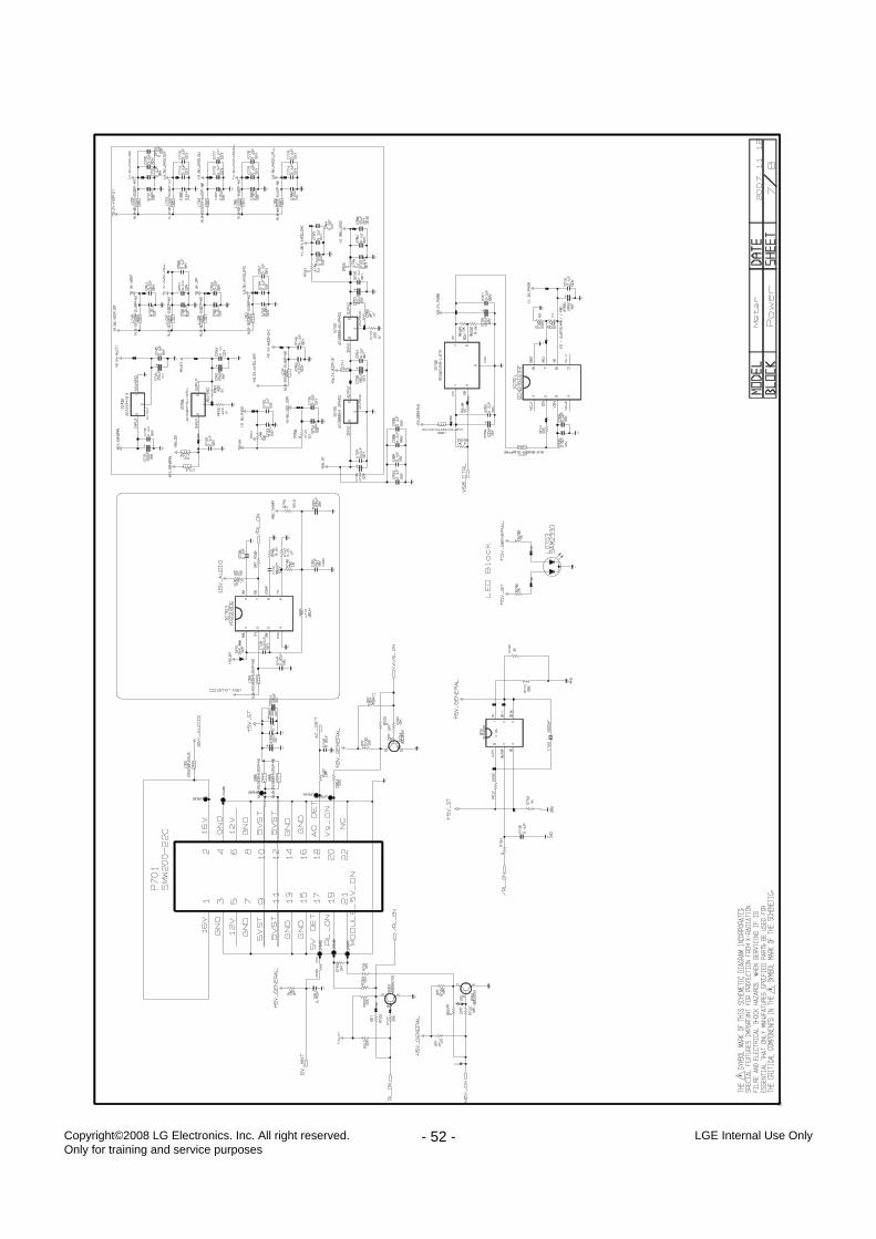
- 52 - LGE Internal Use OnlyCopyright©2008 LG Electronics. Inc. All right reserved. Only for training and service purposes
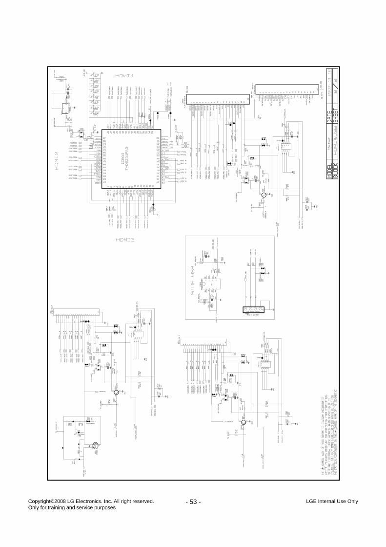
- 53 - LGE Internal Use OnlyCopyright©2008 LG Electronics. Inc. All right reserved. Only for training and service purposes
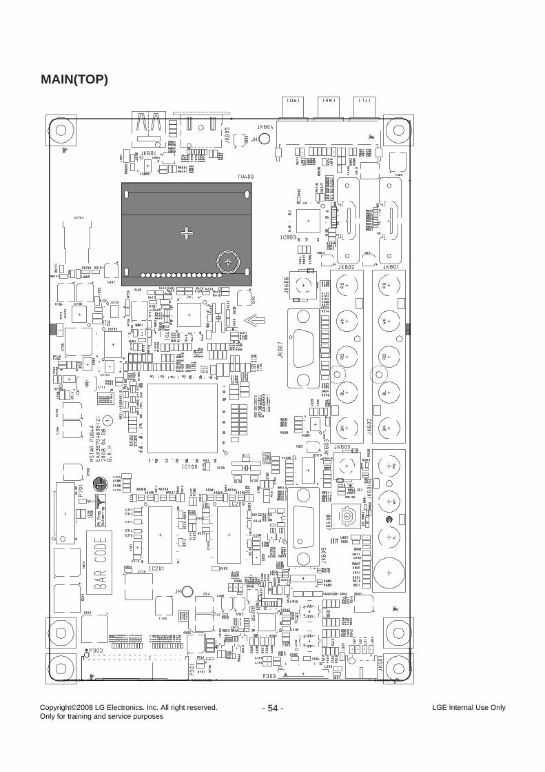
- 54 - LGE Internal Use OnlyCopyright©2008 LG Electronics. Inc. All right reserved. Only for training and service purposes
MAIN(TOP)
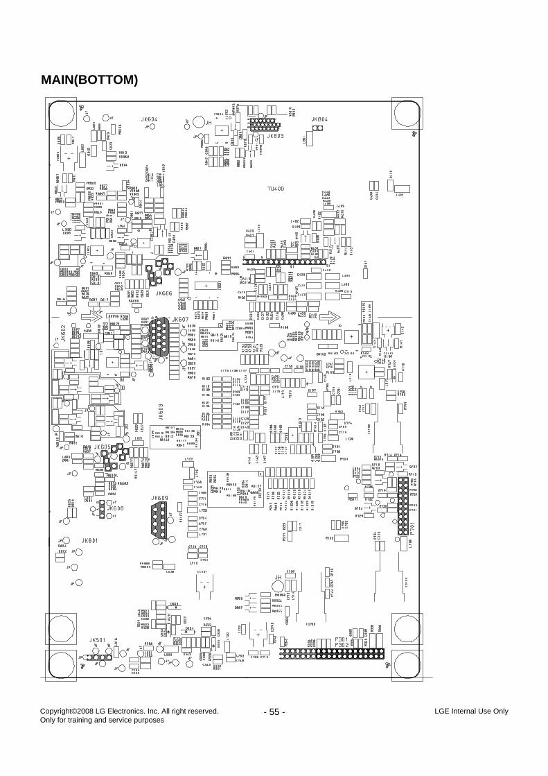
- 55 - LGE Internal Use OnlyCopyright©2008 LG Electronics. Inc. All right reserved. Only for training and service purposes
MAIN(BOTTOM)
- 56 - LGE Internal Use OnlyCopyright©2008 LG Electronics. Inc. All right reserved. Only for training and service purposes
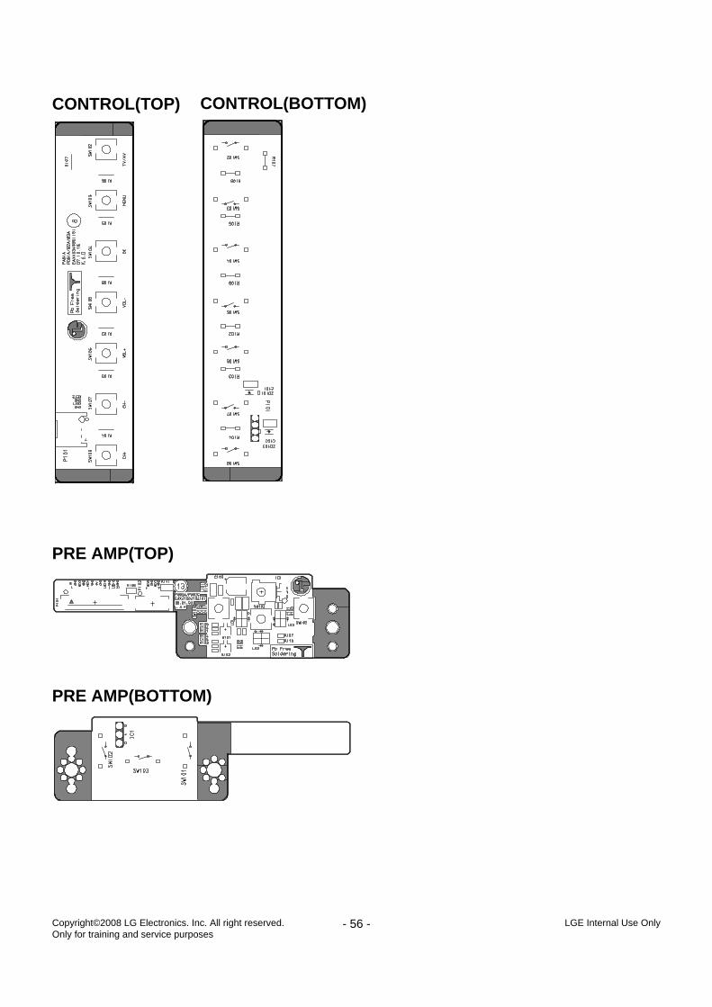
CONTROL(TOP) CONTROL(BOTTOM)
PRE AMP(TOP)
PRE AMP(BOTTOM)
May, 2008Printed in KoreaP/NO : MFL42921702
CANADA: LG Electronics Canada, Inc. 550 MathesonBoulevard East Mississauga, Ontario L4Z 4G3
USA : LG Electronics Alabama, Inc.P.O.Box 240007, 201 James Record Road Bldg 3Huntsville, AL 35824