Embed Size (px)
Citation preview

4" Spin Klin Twin Apollo Battery
Service & Maintenance Manual

2
Table of Contents
Subject Page No.
1. Introduction ................................................................................................ 3
2. Safety Instructions ..................................................................................... 3
3. Description and Operation ......................................................................... 4
4. Technical Data ........................................................................................... 6
5. Headloss Chart ........................................................................................... 6
6. P & ID ......................................................................................................... 7
7. System Maintenance ................................................................................. 8
8. Troubleshooting ......................................................................................... 13
Limited Warranty ........................................................................................... 15
ALL RIGHTS RESERVED, THIS MANUAL AND THE INFORMATION CONTAINED ARE NOT ALLOWED TO BE USED WITHOUT WRITTEN PERMISSION FROM ARKAL FILTRATION SYSTEMS

3
1. Introduction General
Arkal Filtration Systems congratulates you on purchasing the Spin Klin Apollo
For operation and maintenance of the filter please follow the instructions in this manual.
2. Safety Instructions Prior to installation or handling of the filter, read carefully the Installation and Operation
Instructions carefully.
1. Confirm filter draining prior to service.
2. Take precautions while lifting, transporting or installing the filter.
3. Installation of the filter should be performed so as to avoid direct water splashing on any of
the filter parts and especially on the electronic control unit.
4. Confirm that filter weight, when full, meets the support construction requirements.
5.
6. During installation, use standard flanges and connections only.
7. Check that all filter flange bolts are properly secured.
8. Please note, the filter enters a flushing mode automatically, without prior warning.
9. Use original parts only when servicing the filter.
10. Arkal cannot accept responsibility for any changes or modifications to the equipment.
Special Note
Before opening the filter lock, check that there is no pressure in the filter.

4
3. Description and Operation
Table of Filtration Grades of the Discs and Color Code
Color Code Blue Yellow Red Black
Mesh 40 80 120 140
Micron 400 200 130 100
Spin Klin Spine - The Core of the Spin Klin Filtration System
The Spin Klin® discs are stacked on the Spin Klin® spine. The
discs are color-coded according to micron size, and are
assembled to suit your water filtration requirements. The spine
assembly has a spring compression unit and an internal piston,
which operate during alternate filtration or backwash modes. The
spine assembly is specially designed to compress the micron
housing. Inside the housing a spring and the pressure difference
compress the discs tightly during the filtration process, forcing the
water to flow between the grooves and trap the solids.
Spin Klin Automatic Backwash Operation
Activated by a predefined command (differential pressure or
time) alternate units of the Spin Klin® system go into backwash
mode. The inlet valve is shut as the drain is automatically
opened. During the backwash process, the compression spring
is released and the pressure difference is eliminated. The spine
piston rises up, releasing the pressure on the discs. Tangential
jets of clean water are pumped at high pressure in the opposite
direction through nozzles at the center of the spine. The discs
spin free and clear, loosening the trapped solids. Solids are
quickly and efficiently flushed out through the drain.

5
3.3 Mode of Operation
Filtration Process
During the filtration process the water flows through the inlet manifold, reaching the filters through the
backwash valves. The filtered water flow through the outlet manifold into the system.
Backwash Process
The backwash process begins with a signal from the control unit activated by the pressure difference
between the inlet and outlet or by time.
The booster valve opens, causing the No.1 valve to clos
drain port.
Filter No.1 is now in a backwash mode.
The Spin Klin spine in filter No.1 operate simultaneously, releasing the compressed discs. Tangential
jets of water are pumped against the discs, causing them to spin fast and free, flushing trapped solids
out to the drain.
The filtered backwash water is supplied from the other filters through the outlet manifold.
The contaminated water from the backwashed filter drains through the drainage manifold.
Backwash time per filter is between 20 -25 seconds. When the time elapses the control unit stops the
backwash signal to the solenoid.
The solenoid releases the water pressure signal allowing the inlet valve and the discs of the spine to
return to filtration mode.
Once filter No.1 is in the filtration position again the control unit sends a signal to begin the backwash
process in filter No.2.

6
4. Technical Data - 4" Spin Klin Twin ApolloUnits 3 filter
battery4 filter battery
5 filter battery
6 filter battery
7 filter battery
8 filter battery
Max. pressure bar/psi 10/145 10/145 10/145 10/145 10/145 10/145
Min. backwash pressure bar/psi 2/29 2/29 2/29 2/29 2/29 2.0/29
Max. recommended flow rate
130-400μ m3/h/gpm 225/990 300/1,320 375/1,650 450/1,980 525/2,300 600/2,640
100μ m3/h/gpm 180/790 240/1,060 300/1,320 360/1,585 420/1,850 480/2,115
Filtration surface area cm2/in2 15,720/2,435 20,960/3,245 26,200/4,055 31,440/4,865 36,680/5,675 41,920/6,485
Filtration volume cm3/in3 18,852/1,150 25,136/1,534 31,420/1,917 37,704/2,301 43,988/2,684 50,272/3,068
Backwash flow per unit m3/h/gpm 48/210 48/210 48/210 48/210 48/210 48/210
Backwash volume m3/gallon 0.8/210 1/265 1.3/340 1.6/420 1.9/500 2.1/550
System length - L mm/inch 1,450/57 2,240/88 2,740/108 3,240/128 3,740/147 4,240/167
System width - W mm/inch 1,533/60 1,533/60 1,533/60 1,533/60 1,533/60 1,533/60
System height - H mm/inch 1,699/67 1,833/72 1,833/72 1,833/72 1,930/76 1,930/76
Standard diameter mm/inch 200/8 280/10 280/10 280/10 315/12 315/12
depended on the water quality
5. Batteries Headloss Chart - 130 micron, 4" Spin Klin Twin Apollo
10 100
80306040
5025 400
300200100
3
l / s200
3m /h600
HE
AD
LO
SS
(P
SI)
1.50
1.00
10.00
5.00
FLOW RATE , GPM
2000100 200 440 1000 GPM
3.00
2.00
0.57
15 30 60
NUMBER OF FILTERS 3 4 5 6 7 8
1000
4000
8.00
6.00
FLOW RATE , l / s
FLOW RATE , m / h
HE
AD
LO
SS
(kg
/cm
)
2
0.25
0.06
0.040.05
0.20
0.08
0.10
0.15
0.500.40
0.60
0.80
0.30
7
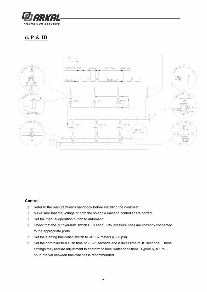
6. P & ID
Control
Make sure that the voltage of both the solenoid unit and controller are correct.
Set the manual operation button to automatic.
to the appropriate ports.
-7 meters (6 - 8 psi).
Set the controller to a flush time of 20-25 seconds and a dwell time of 10 seconds. These
settings may require adjustment to conform to local water conditions. Typically, a 1 to 3
hour interval between backwashes is recommended.

8
7. Apollo Spin Klin - System MaintenanceMonthly Maintenance
Check inlet /outlet pressures:
In case the pressure differential is above 5 m / 7 PSI.
Activate automatic backwash of the Spin Klin filter battery.
In the event that the pressure differential remains high check for possible failures.
Check for leakages from the drain manifold:
In case there is a leakage of water during the filtration stage, check for possible failure at
the backwash valve seals.
Backwash controller performance:
Check that the controller timing parameters are correctly adjusted and activate automatic
backwash cycle. In the event of possible failure at the backwash controller, check for
possible failures.
Cleaning of the Command Filter:
Close the command filter inlet valve. Release the static pressure by opening the drain valve.
Remove the cover. Thoroughly clean the filter element and then reassembly the command
filter element and cover, then open the inlet valve.
Winterization:
In order to prevent the filter battery becoming damaged during water freezing drain all the
water from the filter battery, the command filter and the backwash valves.
9
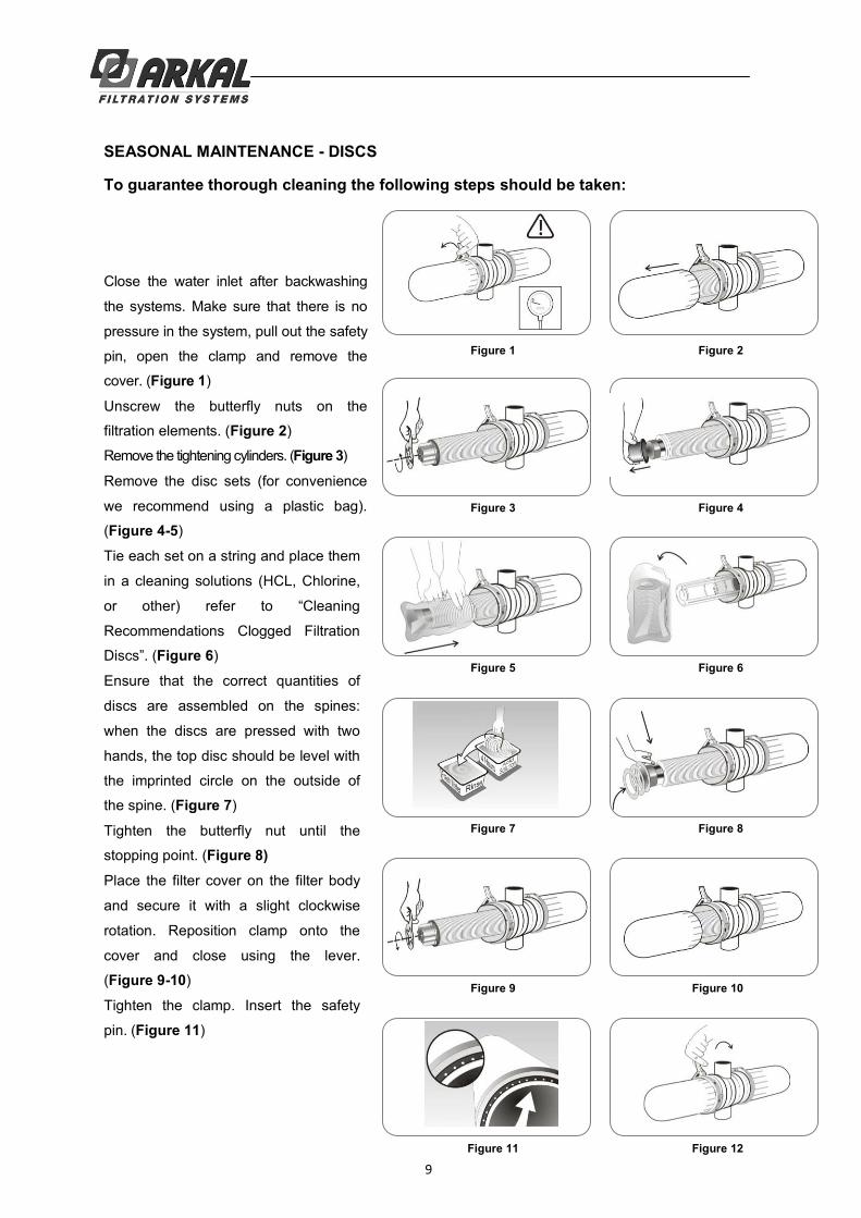
SEASONAL MAINTENANCE - DISCS
To guarantee thorough cleaning the following steps should be taken:
Close the water inlet after backwashing
the systems. Make sure that there is no
pressure in the system, pull out the safety
pin, open the clamp and remove the
cover. (Figure 1)
Unscrew the butterfly nuts on the
filtration elements. (Figure 2)
Remove the tightening cylinders. (Figure 3)
Remove the disc sets (for convenience
we recommend using a plastic bag).
(Figure 4-5)
Tie each set on a string and place them
in a cleaning solutions (HCL, Chlorine,
Recommendations Clogged Filtration
Disc (Figure 6)
Ensure that the correct quantities of
discs are assembled on the spines:
when the discs are pressed with two
hands, the top disc should be level with
the imprinted circle on the outside of
the spine. (Figure 7)
Tighten the butterfly nut until the
stopping point. (Figure 8)
Place the filter cover on the filter body
and secure it with a slight clockwise
rotation. Reposition clamp onto the
cover and close using the lever.
(Figure 9-10)
Tighten the clamp. Insert the safety
pin. (Figure 11)
Figure 1 Figure 2
Figure 3 Figure 4
Figure 5 Figure 6
Figure 7 Figure 8
Figure 9 Figure 10
Figure 11 Figure 12
10
Attention:When carrying out any of the following seasonal maintenance, service, or cleaning the discs After
backwashing the system and after closing the water inlet, make sure that there is no pressure in the system!
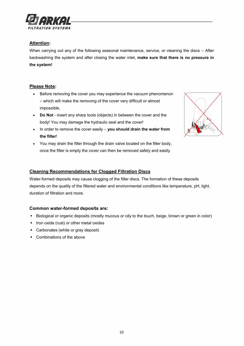
Please Note:Before removing the cover you may experience the vacuum phenomenon
which will make the removing of the cover very difficult or almost
impossible.
Do Not - insert any sharp tools (objects) in between the cover and the
body! You may damage the hydraulic seal and the cover!
In order to remove the cover easily you should drain the water from the filter!
You may drain the filter through the drain valve located on the filter body,
once the filter is empty the cover can then be removed safely and easily.
Cleaning Recommendations for Clogged Filtration Discs Water-formed deposits may cause clogging of the filter discs. The formation of these deposits
depends on the quality of the filtered water and environmental conditions like temperature, pH, light,
duration of filtration and more.
Common water-formed deposits are: Biological or organic deposits (mostly mucous or oily to the touch, beige, brown or green in color)
Iron oxide (rust) or other metal oxides
Carbonates (white or gray deposit)
Combinations of the above

11
If these deposits cannot be eliminated by pretreatment of the water, we recommend the following
cleaning procedure:
Material and Equipment
A well ventilated working place.
2 small containers (1 liter), 2 large containers (15 liter) and a stirring stick, all resistant to
chemicals, preferably of polypropylene.
Plastic rope to tie up the disc.
Sodium Hypochlorite NaOCl -
Strong oxidizing liquid, commercial concentration: 10%.
Oxidizes and removes organic and biological deposits.
Hydrochloric Acid HCl -
Very corrosive liquid, commercial concentration: 30%.
Dissolves and removes carbonates, iron oxide, and other deposits.
Safety equipment: safety glasses, gloves, long pants, long sleeved shirt and shoes.
ATTENTION! While working with chemicals protect yourself with the necessary safety equipment:
Safety glasses, gloves, protective clothing
Work in a well ventilated area
Cleaning Organic and Biological Deposits Open the filter and remove dirty discs.
Attention Never open the filter before the pressure has been released.
Arrange the discs loosely on the plastic rope
Prepare a 5% Sodium Hypochlorite solution:
1) Pour 5 liters of water into one of the large containers.
2) Add 5 liters of Sodium Hypochlorite (10%) into the water.
Soak the discs in the solution so that both sides are covered. To achieve maximum cleaning,
agitate the discs several times with a stirring stick.
Contact time with cleaning solution: up to 8 hours
Remove the discs carefully from the solution, put them in the second large container and rinse
them very well with clean water before placing them back in the filter.
We recommend flushing the cleaned discs again in the filter to ensure that all chemical residues
are removed.
The cleaning solution can be used for several sets of discs. As the cleaning activity of the solution
deteriorates, it may be necessary to soak the discs for a longer time.

12
Cleaning Carbonates and Iron Deposits Open the filter and remove the dirty discs.
Arrange the discs loosely on the plastic rope.
Prepare a 5% Solution of Hydrochloric Acid:
1) Pour 10 liters of water into one of the large containers.
2) Carefully add 2 liters of Hydrochloric Acid (30%) into the water.
Soak the discs in the solution so that both sides will be covered.
PLEASE NOTE: Carbonates react violently with hydrochloric acid (foaming, gas evolution).
To achieve maximum cleaning, agitate the discs several times with a stirring stick.
Contact time with cleaning solution: 1 - 8 hours.
Remove the discs carefully from the solution and rinse them well with clean water before placing them
back in the filter.
We recommend flushing the cleaned discs again in the filter to ensure that all chemical residues are
removed.
The cleaning solution can be used for several sets of discs. It may be necessary to soak the discs for a longer
period of time as the cleaning activity of the solution deteriorates.
Cleaning Complex Deposits If the composition of the deposit is not known, perform the following test:
Take 5 discs for the test.
Soak 2 discs in a 5% Sodium Hypochlorite Solution.
Preparation of the solution:
Pour 1 cup of water into a small container, then add 1 cup of Sodium Hypochlorite (10% NaOCl).
Soak 2 discs in a 5% Hydrochloric Acid Solution.
Preparation of the solution:
Pour 2½ cups (= 500ml) of water into a small container, then add carefully
½ cup (= 100ml) of Hydrochloric Acid (30% HCl).
Keep one disc as a control.
Observe the cleaning process:
If one of the solutions removes all of the deposit, clean the discs in that solution according to the
instructions above.
If neither solution removes the deposit completely, continue with the test procedure.
Remove the discs from both solutions, rinse them well with water and soak them in the second solution:
put the two discs, which have been in the Sodium Hypochlorite Solution, in the Hydrochloric Acid Solution,
and the other way round.
Check the cleaning process:
If one of the treatments removes all of the deposit, clean all of the discs following the same two-step
procedure in the exact same order. Rinse the discs well between the two cleaning processes. If the deposit

13
8. TroubleshootingNo Backwash Operation
Check inlet and outlet pressures
Check & clean command filter
Check controller manually operate the backwash cycle
No command transfer Functioning correctly Some commands do not function
Check electrical source Replace battery if needed
Check electrical source Replace battery if needed
Check solenoid electrical connectors
Repair or replace the solenoid
Check the booster valve
Command not received Functioning correctly Receives command
Check the 8mm command tube
Repair or replace the booster valve if needed
Check the valves
Command not received Receives command
Check the water supply control tube Check the diaphragm and the
piston Replace if needed
Check & clean the drain manifold and pipe
Contact your local distributor

14
Identifying Malfunctions in the Apollo system
Continuous or Non-stop Backwashing Continuous backwash Nonstop backwash cycle
Disconnect the control pipes from the valves
Check inlet / outlet pressure Check pressure differential gauge and replace if needed
Check controller described above
Contact your local distributor
Command transfer No command transfer
Disconnect the drain manifold
Check controller Locate the nonfunctioning valve
Remove any obstruction Repair the valve if needed
No command transfer Command transfer Replace control panel
Check the solenoid
No command transfer Command transfer Replace the solenoid
if needed
Check the booster valve
No command transfer Command transfer Replace the booster
valve if needed
Contact your local distributor

15
Limited Warranty
urchased ARKAL FILTRATION SYSTEMS products directly from Arkal or
through one of its authorized distributors, that such products will be free from defect in material
and/or workmanship for the term set forth below, provide that such products are properly installed,
used and maintained in accordance with ARKAL FILTRATION SYSTEMS instructions, written or
verbal.
Should such products prove defective within one year from the original purchase date by the customer,
and subject to receipt by ARKAL FILTRATION SYSTEMS or its authorized representative, of written
notice thereof from the customer within 30 days of discovery of such defect or failure - ARKAL
FILTRATION SYSTEMS will repair or replace, at its sole discretion, any item proven to be defective.
ARKAL FILTRATION SYSTEMS shall not be liable, nor does this warranty extend to any
consequential or incidental damages or expenses of any kind or nature, regardless of the nature
thereof, including without limitation, injury to persons or property, loss of use of the products, loss of
goodwill, loss of profits or any other contingent liabilities of any kind or character alleged to be the
cause of loss or damage to the purchaser.
This warranty does not cover damage or failure caused by misuse, abuse or negligence, nor shall it
apply to such products upon which repairs or alterations have been made by other than an
authorized ARKAL FILTRATION SYSTEMS representative.
This warranty does not extend to components, parts or raw materials used by ARKAL FILTRATION
SYSTEMS but manufactured by others, which shall be only to the extent warranted by the
manufacturer's warranty.
No agents or representatives shall have the authority to alter the terms of this warranty nor to add
any provisions to it not contained herein or to extend this warranty to anyone other than ARKAL
FILTRATION SYSTEMS customers.
THERE ARE NO WARRANTIES, EXPRESS OR IMPLIED, EXCEPT THIS WARRANTY WHICH IS
GIVEN IN LIEU OF ANY OTHER WARRANTIES, EXPRESS OR IMPLIED, INCLUDING ANY
IMPLIED WARRANTY OF MERCHANTABILITY AND FITNESS FOR A PARTICULAR PURPOSE.
4-6A
pollo
SK
Ser
vice
& M
aint
enan
ce 1
2-20
08 E
NG