Embed Size (px)
Citation preview
��
1050 Series of HPLC Modules
Service Handbook - Variable Wavelength Detector (79853C)
Agilent TechnologiesHewlett-Packard-Strasse 876337 WaldbronnGermany
Copyright Agilent Technologies 2001
All rights reserved. Reproduction, adaption, or translation without prior written permission is prohibited, except as allowed under the copyright laws.
Part No. NONE
11/2001
Printed in Germany
Warranty
The information contained in this document is subject to change without notice.
Agilent Technologies
makes no warranty of
any kind with regard to
this material,
including, but not
limited to, the implied
warranties or
merchantability and
fitness for a particular
purpose.
Agilent Technologies shall not be liable for errors contained herein or for incidental or consequential damages in connection with the furnishing, performance, or use of this material.
IMPORTANT NOTE
This version of the 1050 service manual includes all sections from the 01050-90102 edition 4 (1995).
The series I opticals information (79854A MWD) and the 79853A VWD information has been removed (products went out of support during 2000).
Part numbers have been updated as of 11/2001. Contact your local Agilent support office in case of part number issues or upgrades.
The latest version of this manual is available as Adobe Acrobat Reader (PDF) version only and can be downloaded from the Agilent Technolgies web page www.agilent.com.
1Contents
1 VWD: General Information
This chapter provides general information about the 1050
Variable Wavelength Detectors 11
About the Detector 13Versions vs. Support Periods (EOS) 13
79853A 1379853C 13
Repair Policy 14Specifications 15
2 VWD: Hardware Information
This chapter provides hardware information about the 1050
Variable Wavelength Detectors 17
Overview 18Optical System Overview 20Leak Interface Assembly 21Leak Sensor Assembly 22Fan Assemblies 23Optical Unit 24
Flow Cells 25Deuterium Lamp 28Photodiodes Assemblies 31Filter Assembly 32Grating Assembly and Motor 33Mirrors 34Slit Assemblies 34Beam Splitter 34
Enhanced Optical Unit (“D”) 35
Service Handbook for 1050 Series of HPLC Modules - 11/2001 3
Contents
3 VWD: Electronic Information
This chapter provides electronic information about the 1050
Variable Wavelength Detectors 37
Location of Electronic Assemblies 39Interconnection Diagram 41Detector Controller Board (DCB) 42
Digital Section 44Analog Sections 46
Power Supply (DPS-A) 53Keyboard 54
Keyboard Electronics (KDI / VFD) 55
Pre-Amplifier Boards 57Power Supply Connection Board (PSC) 58GPIB Communication Interface 59
GPIB Firmware Revisions 60
4 VWD: Diagnostic & Troubleshooting Information
This chapter provides information on error messages and di-
agnostic features of the 1050 Variable Wavelength
Detectors 61
Self Diagnosis 63During Power On 63During Normal Operation 63
Error Messages Before Lamp Ignition 64At Power ON 64
Error Messages After Lamp Ignition 68Error Messages During Normal Operation 69Error Messages During Use of Control Functions 71
4 Service Handbook for 1050 Series of HPLC Modules - 11/2001
Contents
User Control Functions 72Service Control Functions 74
Entering the Service Mode 74Zero Order Calibration 76Wavelength Calibration 78Wavelength Calibration Check 80SET WL Parameter 81Fix Signal 83Leak Sensor Voltage 86Voltage Test 87ADC Noise 88Grating Photo Sensor 89Filter Photo Sensor 90Remote Test 91Filter Check 92Zero Order Test 93DAC Test 94Pre-amplifier Gain 96EEROM Test 97DAC Calibration 98Wavelength Compensation 99
5 VWD: Maintenance Information
This chapter provides provide procedures for service and main-
tenance of the 1050 Variable Wavelength Detectors 101
Warnings 102Securing for Transport 103Replacement of Deuterium Lamp 104
Step 1: Replacement 104Step 2: 0th Order Calibration 105
Service Handbook for 1050 Series of HPLC Modules - 11/2001 5
Contents
Step 3: WL CALIBRATION 106
Flow Cell Maintenance 107Flow Cell Maintenance Kits 107Replacing Cell Parts 107Flushing Procedure 108Leak Test 109
Using the Cuvette Holder 110Replacing DCB Board and Firmware 113
DCB Board 113DCB Firmware 113
Replacing Display Boards 114Replacing the Leak Interface 115
Leak Sensor Assembly 115Leak Interface 116
Replacements in the Optical Unit 117Removing the Optical Unit 118Replacing the PSC Board 119Replacing Pre-amplifiers or Photodiodes 119Replacing Grating Assembly Parts 120Replacing Filter Assembly Parts 122Replacing Mirrors, Beamsplitter and Slits 122
Optical Alignment Procedures 123Procedure 1: Simple Alignment 123Procedure 2: Sample Beam Alignment 124Procedure 3: Reference Beam Alignment 126
Cleaning of Optical Unit Parts 127Upgrade to GPIB 128Performance Verification 129
What you need 129Preparations 129Starting a run 130Scaling Factors 131
6 Service Handbook for 1050 Series of HPLC Modules - 11/2001
Contents
6 VWD: Parts Information
This chapter provides information on parts of the 1050 Vari-
able Wavelength Detectors 133
Overall Diagram 135Front Panel Parts 138
Leak Interface 138Font Panel 139
Optical Unit “C” 140Optical Unit “C” Inner Parts Top 141Optical Unit “C” Inner Parts Bottom 142
Grating Assembly 143Filter Assembly 144Standard Flow Cell “C” (SST/Ti) 145Semi-Micro Flow Cell (SST) 147High Pressure Flow Cell (SST) 148Ultra High Pressure Flow Cell (SST) 149Preparative Flow Cell (Ti) 150Cuvette Holder 152Accessories 153Screws 154
7 VWD: Enhanced Optical Unit Information
This chapter provides information about the enhanced optical
unit “D” 157
Compatibility 158Support of Previous Optical Units 158Introduction 159Support Considerations 160
Service Handbook for 1050 Series of HPLC Modules - 11/2001 7
Contents
Prefix Change 160Identification 160Compatibility Matrix 160
Part Numbers for Enhanced “D” Optical Unit 161Standard Flow Cell “D” Repair Parts 162Repair and Mainenance 163
Tools required: 163Pre-requisites: 163
Additional Information 164Replacements and Calibrations 164Installing the Test Slit 165Replacing Mirror #1 Assembly 167Replacing Mirror #3 or #4 Assembly 168Replacing the Grating or Grating Motor 170Replacing the Beam Splitter 172Cleaning or Replacing the Lens 173Unlocking the Reference Aperture 175Optimizing the Reference Readings 177Installing the Standard Slit 178
8 VWD: Additional Information
This chapter provides additional information about the 1050
Variable Wavelength Detectors 179
Product History 181Prefix Changes 181
DCB ROM Firmware Revisions 183GPIB ROM Firmware Revisions 185Hardware Changes and Service Notes 186
Modified Pre-Amplifier Gain 186
8 Service Handbook for 1050 Series of HPLC Modules - 11/2001
Contents
Important Service Note 186
Service Handbook for 1050 Series of HPLC Modules - 11/2001 9

Contents
10 Service Handbook for 1050 Series of HPLC Modules - 11/2001

1
1 VWD: General Information
This chapter provides general information about the 1050 Variable Wavelength Detectors
VWD: General Information
This chapter gives general information on
• about this detector
• repair policy
• specifications
560 Service Handbook for 1050 Series of HPLC Modules - 11/2001
VWD: General InformationAbout the Detector
About the Detector
The 1050 Variable Wavelength Detector (VWD) is a detector of the modular type liquid chromatograph 1050 Series. This is a standalone grating/photodiode type general purpose detector. The performance and features match the requirements of the routine analysis and QC/QA analysis. The 1050 VWD is a standard size detector of 1050 modular type LC series and can be build up with other LC modules, such as pump and automatic sampler. Since it is standalone type, it can be also used as an ordinary LC detector. It has a functional keyboard and 16-character fluorescent display which provides you easy operation.
Versions vs. Support Periods (EOS)
79853A
• The 79853A VWD was shipped between May 1988 and January 1992. The support with parts ended November 1, 2000.
79853C
• The 79853C VWD replaced the model 79853A VWD in January 1992. The end of support (EOS) will be August 1, 2006 with all 1050 series HPLC modules.
• The 79853C VWD got a redesigned optical unit (“D” enhanced optical, see “VWD: Enhanced Optical Unit Information” on page 705) that replaced the original “C” optical unit in June 1995. The end of support (EOS) for the “C” optical unit parts will be August 1, 2006 with all 1050 series HPLC modules.
Service Handbook for 1050 Series of HPLC Modules - 11/2001 561
VWD: General InformationRepair Policy
Repair Policy
The 1050 VWD is designed that you can access all components easily. You can recalibrate wavelength using control functions. Customers are able to maintain certain parts of the 1050 VWD see Operator’s Handbook.
For details on repair policy refer to “Repair Policy” on page 38 in chapter 1050 Common Information.
562 Service Handbook for 1050 Series of HPLC Modules - 11/2001
VWD: General InformationSpecifications
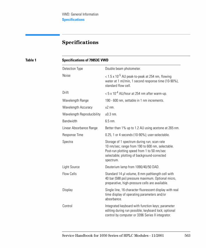
Specifications
Table 1 Specifications of 79853C VWD
Detection Type Double beam photometer.
Noise < 1.5 x 10⁻⁵ AU peak-to-peak at 254 nm, flowing water at 1 ml/min, 1 second response time (10-90%), standard flow cell.
Drift < 5 x 10⁻⁴ AU/hour at 254 nm after warm-up.
Wavelength Range 190 - 600 nm, settable in 1 nm increments.
Wavelength Accuracy ±2 nm.
Wavelength Reproducibility ±0.3 nm.
Bandwidth 6.5 nm.
Linear Absorbance Range Better than 1% up to 1.2 AU using acetone at 265 nm.
Response Time 0.25, 1 or 4 seconds (10-90%); user-selectable.
Spectra Storage of 1 spectrum during run; scan rate 10 nm/sec; range from 190 to 600 nm, selectable. Post-run plotting speed from 1 to 50 nm/sec selectable; plotting of background-corrected spectrum.
Light Source Deuterium lamp from 1090/40/50 DAD.
Flow Cells Standard 14 µl volume, 8 mm pathlength cell with 40 bar (588 psi) pressure maximum. Optional micro, preparative, high-pressure cells are available.
Display Single line, 16 character fluorescent display with real time display of operating parameters and/or absorbance.
Control Integrated keyboard with function keys; parameter editing during run possible; keyboard lock; optional control by computer or 3396 Series II integrator.
Service Handbook for 1050 Series of HPLC Modules - 11/2001 563
VWD: General InformationSpecifications
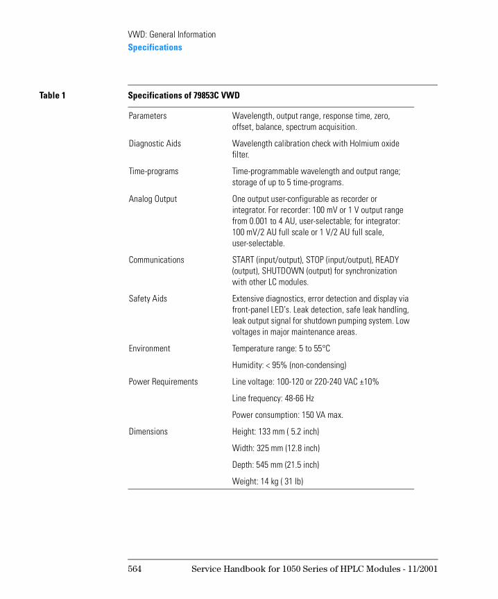
Parameters Wavelength, output range, response time, zero, offset, balance, spectrum acquisition.
Diagnostic Aids Wavelength calibration check with Holmium oxide filter.
Time-programs Time-programmable wavelength and output range; storage of up to 5 time-programs.
Analog Output One output user-configurable as recorder or integrator. For recorder: 100 mV or 1 V output range from 0.001 to 4 AU, user-selectable; for integrator: 100 mV/2 AU full scale or 1 V/2 AU full scale, user-selectable.
Communications START (input/output), STOP (input/output), READY (output), SHUTDOWN (output) for synchronization with other LC modules.
Safety Aids Extensive diagnostics, error detection and display via front-panel LED’s. Leak detection, safe leak handling, leak output signal for shutdown pumping system. Low voltages in major maintenance areas.
Environment Temperature range: 5 to 55°C
Humidity: < 95% (non-condensing)
Power Requirements Line voltage: 100-120 or 220-240 VAC ±10%
Line frequency: 48-66 Hz
Power consumption: 150 VA max.
Dimensions Height: 133 mm ( 5.2 inch)
Width: 325 mm (12.8 inch)
Depth: 545 mm (21.5 inch)
Weight: 14 kg ( 31 lb)
Table 1 Specifications of 79853C VWD
564 Service Handbook for 1050 Series of HPLC Modules - 11/2001
1
1 VWD: Hardware Information
This chapter provides hardware information about the 1050 Variable Wavelength Detectors
VWD: Hardware Information
Overview
N OT E The information in this chapter is based on the original optical unit (version “C”). In June 1995 this optical was replaced by the enhanced version “D” to overcome baseline stability problems in unstable environments.
For details on this “D” version refer to section Enhanced Optical Unit Information “VWD: Enhanced Optical Unit Information” on page 705.
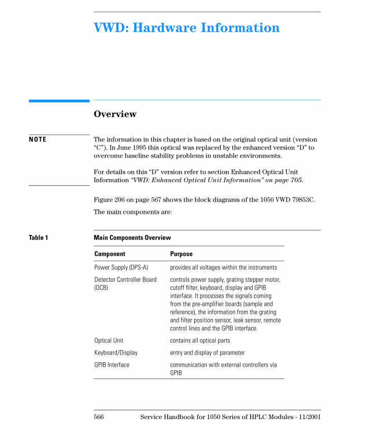
Figure 206 on page 567 shows the block diagrams of the 1050 VWD 79853C.
The main components are:
Table 1 Main Components Overview
Component Purpose
Power Supply (DPS-A) provides all voltages within the instruments
Detector Controller Board (DCB)
controls power supply, grating stepper motor, cutoff filter, keyboard, display and GPIB interface. It processes the signals coming from the pre-amplifier boards (sample and reference), the information from the grating and filter position sensor, leak sensor, remote control lines and the GPIB interface.
Optical Unit contains all optical parts
Keyboard/Display entry and display of parameter
GPIB Interface communication with external controllers via GPIB
566 Service Handbook for 1050 Series of HPLC Modules - 11/2001
VWD: Hardware InformationOverview
Figure 1 Block Diagram of VWD
Service Handbook for 1050 Series of HPLC Modules - 11/2001 567
VWD: Hardware InformationOptical System Overview
Optical System Overview
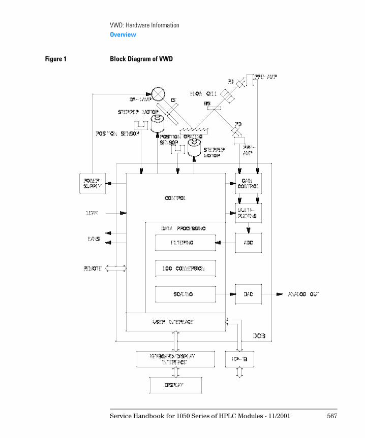
Figure 207 shows the optical diagram of the 79853C VWD. The radiation from the deuterium lamp is focused on a spherical mirror (M1). The light beam passes then a plane mirror (M2) the cutoff filter, the entrance slit, a spherical mirror (M3), the grating, again a spherical mirror (M4), a beam splitter and the flow cell to the sample diode. The beam through the flow cell is absorbed depending on the solutions in the cell, where UV absorption takes place. The intensity is converted to an electrical signal by means of the sample photodiode. Part of the light is directed to the reference photodiode by the beam splitter to obtain reference signal for compensation of intensity fluctuation of the light source. A slit in front of the reference photodiode focusses the light. Wavelength selection is made by rotating the grating, which is driven directly by a stepper motor. This configuration allows fast change of the wavelength. The cutoff filter is moved into the lightpath above 370 nm to reduce higher order light.
Figure 2 Light Path of Detector
568 Service Handbook for 1050 Series of HPLC Modules - 11/2001
VWD: Hardware InformationLeak Interface Assembly
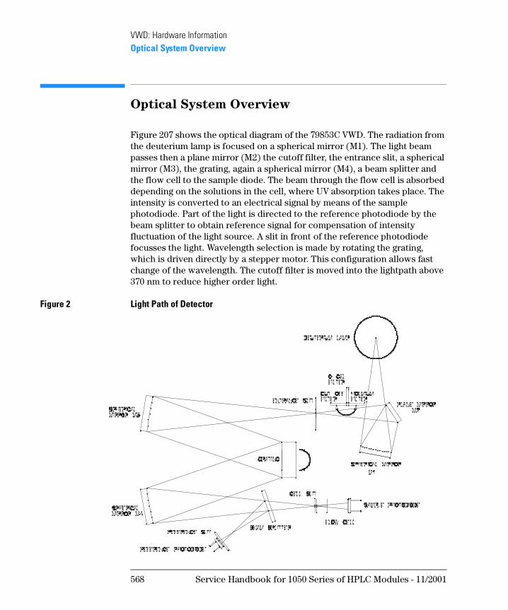
Leak Interface Assembly
To route waste from a module standing above the 1050 VWD to a module below a leak interface can be installed at the detector. It is part of the accessory kit.
Figure 3 Leak Interface
Service Handbook for 1050 Series of HPLC Modules - 11/2001 569
VWD: Hardware InformationLeak Sensor Assembly
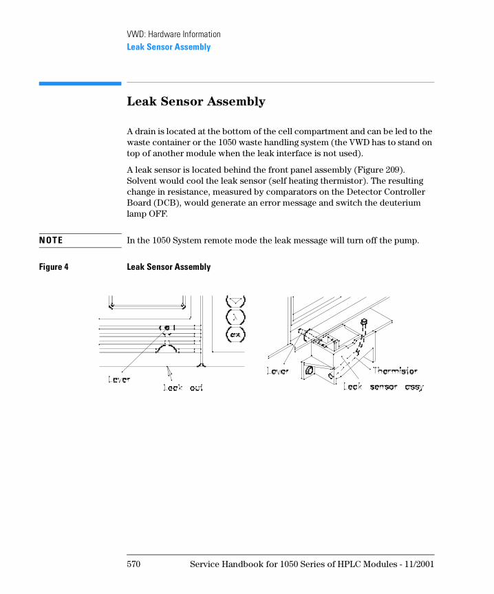
Leak Sensor Assembly
A drain is located at the bottom of the cell compartment and can be led to the waste container or the 1050 waste handling system (the VWD has to stand on top of another module when the leak interface is not used).
A leak sensor is located behind the front panel assembly (Figure 209). Solvent would cool the leak sensor (self heating thermistor). The resulting change in resistance, measured by comparators on the Detector Controller Board (DCB), would generate an error message and switch the deuterium lamp OFF.
N OT E In the 1050 System remote mode the leak message will turn off the pump.
Figure 4 Leak Sensor Assembly
570 Service Handbook for 1050 Series of HPLC Modules - 11/2001
VWD: Hardware InformationFan Assemblies
Fan Assemblies
The instrument is equipped with two fans.
On the 79853C VWD, the fans are of different type:
The fans are connected to +24 VDC on the DCB Board.
HIGH type this fan is located close to the lamp housing and runs with a higher speed
LOW type this fan is located at the rear under the GPIB interface and runs with a lower speed
Service Handbook for 1050 Series of HPLC Modules - 11/2001 571
VWD: Hardware InformationOptical Unit
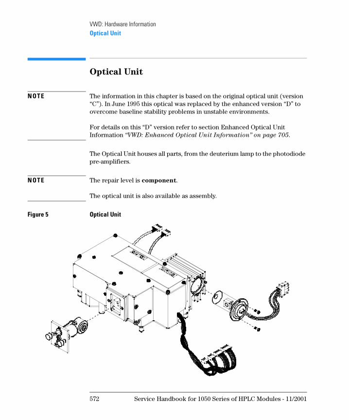
Optical Unit
N OT E The information in this chapter is based on the original optical unit (version “C”). In June 1995 this optical was replaced by the enhanced version “D” to overcome baseline stability problems in unstable environments.
For details on this “D” version refer to section Enhanced Optical Unit Information “VWD: Enhanced Optical Unit Information” on page 705.
The Optical Unit houses all parts, from the deuterium lamp to the photodiode pre-amplifiers.
N OT E The repair level is component.
The optical unit is also available as assembly.
Figure 5 Optical Unit
572 Service Handbook for 1050 Series of HPLC Modules - 11/2001
VWD: Hardware InformationOptical Unit
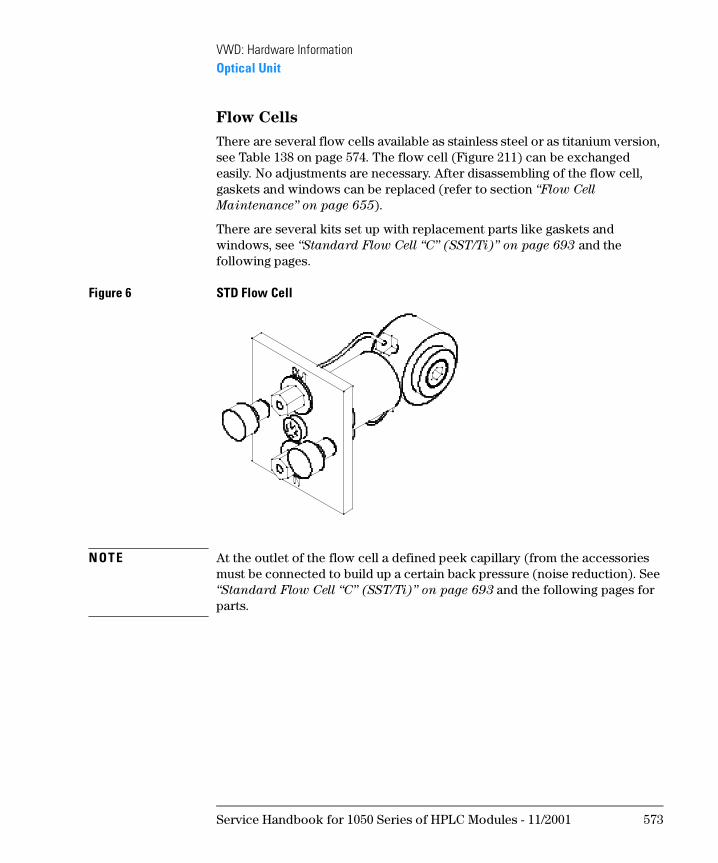
Flow Cells
There are several flow cells available as stainless steel or as titanium version, see Table 138 on page 574. The flow cell (Figure 211) can be exchanged easily. No adjustments are necessary. After disassembling of the flow cell, gaskets and windows can be replaced (refer to section “Flow Cell
Maintenance” on page 655).
There are several kits set up with replacement parts like gaskets and windows, see “Standard Flow Cell “C” (SST/Ti)” on page 693 and the following pages.
Figure 6 STD Flow Cell
N OT E At the outlet of the flow cell a defined peek capillary (from the accessories must be connected to build up a certain back pressure (noise reduction). See “Standard Flow Cell “C” (SST/Ti)” on page 693 and the following pages for parts.
Service Handbook for 1050 Series of HPLC Modules - 11/2001 573
VWD: Hardware InformationOptical Unit
N OT E The gaskets, windows and rings are not compatible with the high pressure Cell (79853-60009 - OBSOLETE) that has been replaced by the ultra high pressure Cellflow cell (79853-60013). See “Ultra High Pressure Flow Cell
(SST)” on page 697 for details.
Table 2 Flow Cell Data
STD (SST)
UHP (SST)
MICRO (SST)
STD (TI)
PREP (TI)
Maximum Pressure 40 400 40 40 40 bar
Pathlength 8 8 5 8 VAR mm
Volume 14 14 1 14 VAR µl
Inlet i.d. 0.25 0.25 0.10 0.25 0.80 mm
Inlet length 555 555 555 555 67 mm
Outlet i.d. 0.25 0.25 0.25 0.25 0.80 mm
Outlet length 67 67 67 67 100 mm
Outer diameter 1/16 1/16 1/16 1/16 1/16 inch
Used materials for SST flow cells: SST, quartz and PTFE or Polyimide HP cell
Used materials for TI flow cells: TI, quartz and PTFE
STD Standard Flow Cell
HP High Pressure Flow Cell (replaced by UHP early 1993)
UHP Ultra High-Pressure Flow Cell (replaces HP early 1993), see details on “Ultra High-Pressure Flow Cell” on page 575.
PREP Variable Preparative Flow Cell with volume of 0.9, 1.8, 4.4 or 8.8 µl depending on which gasket is used.
MICRO Semi Micro Flow Cell
574 Service Handbook for 1050 Series of HPLC Modules - 11/2001
VWD: Hardware InformationOptical Unit
Ultra High-Pressure Flow Cell
Typical applications of the high-pressure flow cells are:
• Hyphenated systems (LC-MS)
• Supercritical Fluid Chromatography (SFC)
• Multidetector systems
• Narrow-bore column applications
The main difference between the standard and high-pressure flow cells is the design of the window assemblies. The high-pressure flow cells have different windows, seal ring and gaskets, see Figure 212. The seal rings support and hold the window and at the same time form the high-pressure seal.
N OT E The gaskets, windows and rings are not compatible with the high pressure Cell (79853-60009 - OBSOLETE) that has been replaced by the ultra high pressure Cellflow cell (79853-60013). See “Ultra High Pressure Flow Cell
(SST)” on page 697 for details.
The following materials are in contact with solvents: Stainless steel (AISI 316), Quartz, Kapton® polyimide (Kapton is a registered trademark of DuPont).
Recommended pH range: 2.3 to 9.5
Table 3 Correction factors for 79853C flow cells
Flow cell type Cell volume Part numberPath length(nominal)
Path length(actual)
Correctionfactor
Standard flow cell 14 µl 79853-60000 8 mm 8.00 ± 0.19 mm 8/8.05
Standard flow cell TI 14 µl 79853-60011 8 mm 8.00 ± 0.19 mm 8/8.00
Micro flow cell 1 µl 79853-60010 5 mm 5.00 ± 0.19 mm 5/5.00
Ultra High pressure flow cell 14 µl 79853-60013 8 mm 8.00 ± 0.19 mm 8/8.00
Service Handbook for 1050 Series of HPLC Modules - 11/2001 575
VWD: Hardware InformationOptical Unit
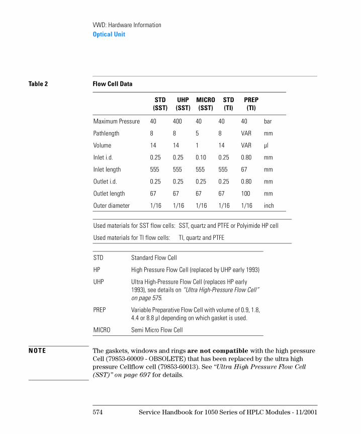
Figure 7 Exploded Diagram of High-Pressure Flow Cell
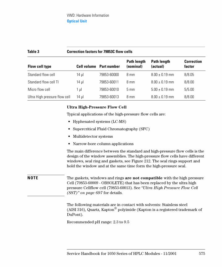
Deuterium Lamp
On the 79853C VWD, the deuterium lamp (Figure 213) is the high intensity lamp (79883-60002), which is same as in the 1040/90/50 series Diode Array Detectors.
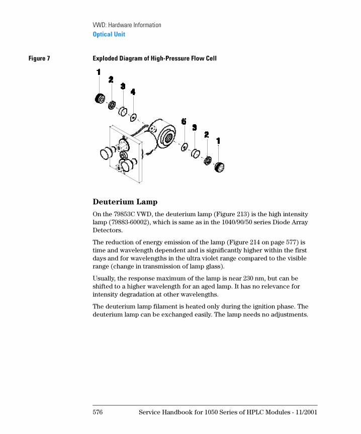
The reduction of energy emission of the lamp (Figure 214 on page 577) is time and wavelength dependent and is significantly higher within the first days and for wavelengths in the ultra violet range compared to the visible range (change in transmission of lamp glass).
Usually, the response maximum of the lamp is near 230 nm, but can be shifted to a higher wavelength for an aged lamp. It has no relevance for intensity degradation at other wavelengths.
The deuterium lamp filament is heated only during the ignition phase. The deuterium lamp can be exchanged easily. The lamp needs no adjustments.
576 Service Handbook for 1050 Series of HPLC Modules - 11/2001
VWD: Hardware InformationOptical Unit
Figure 8 Deuterium Lamp
Figure 9 Intensity Degradation of Lamp (79883-60002)
• Measured wavelength is 230 nm
• initial intensity about 20% higer than 79880-60002
• decrease in intensity is less with use
Service Handbook for 1050 Series of HPLC Modules - 11/2001 577
VWD: Hardware InformationOptical Unit
N OT E The lamp should be replaced only if the following two criterias are both fulfilled:
Baseline Noise (with test cell) has increased significantly.
Amount of counts of the lamp (with test cell) has decreased to less than 50% of the count record of this same lamp when newly installed).
The decision to replace the lamp due to criterium 2 alone is not relevant, because the signal/noise may be still within instrument specifications.
578 Service Handbook for 1050 Series of HPLC Modules - 11/2001
VWD: Hardware InformationOptical Unit
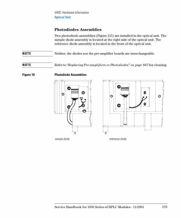
Photodiodes Assemblies
Two photodiode assemblies (Figure 215) are installed in the optical unit. The sample diode assembly is located at the right side of the optical unit. The reference diode assembly is located in the front of the optical unit.
N OT E Neither, the diodes nor the pre-amplifier boards are interchangeable.
N OT E Refer to “Replacing Pre-amplifiers or Photodiodes” on page 667 for cleaning.
Figure 10 Photodiode Assemblies
sample diode reference diode
Service Handbook for 1050 Series of HPLC Modules - 11/2001 579
VWD: Hardware InformationOptical Unit
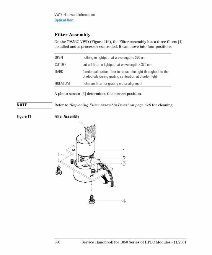
Filter Assembly
On the 79853C VWD (Figure 216), the Filter Assembly has a three filters [1] installed and is processor controlled. It can move into four positions:
A photo sensor [3] determines the correct position.
N OT E Refer to “Replacing Filter Assembly Parts” on page 670 for cleaning.
Figure 11 Filter Assembly
OPEN nothing in lightpath at wavelength < 370 nm
CUTOFF cut off filter in lightpath at wavelength > 370 nm
DARK 0 order calibration filter to reduce the light throughput to the photodiode during grating calibration at 0 order light
HOLMIUM holmium filter for grating motor alignment
580 Service Handbook for 1050 Series of HPLC Modules - 11/2001
VWD: Hardware InformationOptical Unit
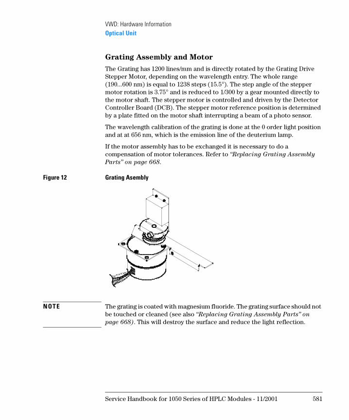
Grating Assembly and Motor
The Grating has 1200 lines/mm and is directly rotated by the Grating Drive Stepper Motor, depending on the wavelength entry. The whole range (190...600 nm) is equal to 1238 steps (15.5°). The step angle of the stepper motor rotation is 3.75° and is reduced to 1/300 by a gear mounted directly to the motor shaft. The stepper motor is controlled and driven by the Detector Controller Board (DCB). The stepper motor reference position is determined by a plate fitted on the motor shaft interrupting a beam of a photo sensor.
The wavelength calibration of the grating is done at the 0 order light position and at at 656 nm, which is the emission line of the deuterium lamp.
If the motor assembly has to be exchanged it is necessary to do a compensation of motor tolerances. Refer to “Replacing Grating Assembly
Parts” on page 668.
Figure 12 Grating Asembly
N OT E The grating is coated with magnesium fluoride. The grating surface should not be touched or cleaned (see also “Replacing Grating Assembly Parts” on
page 668). This will destroy the surface and reduce the light reflection.
Service Handbook for 1050 Series of HPLC Modules - 11/2001 581
VWD: Hardware InformationOptical Unit
Mirrors
The instrument contains four mirrors (M1, M2, M3, M4). Three of them are spherical type, one plane. On M2, M3 and M4 the beam height is adjustable. Mirror M3 and M4 are identical.
N OT E The mirrors are coated with magnesium fluoride. They should not be touched or cleaned (see also “Replacing Mirrors, Beamsplitter and Slits” on
page 670). This will destroy the surface and reduce the light reflection.
Slit Assemblies
The instrument has two slit assemblies. The first slit is located at the light entry into the main optical compartment and focused the light on mirror M3. The second slit is in front of the reference diode.
Beam Splitter
The beam splitter splits the light beam. One part goes directly to the sample diode. The reference diode gets the other part. The height of the light beam is adjustable.
Refer to “Replacing Mirrors, Beamsplitter and Slits” on page 670 for cleaning.
582 Service Handbook for 1050 Series of HPLC Modules - 11/2001
VWD: Hardware InformationEnhanced Optical Unit (“D”)
Enhanced Optical Unit (“D”)
In June 1995 this original optical unit was replaced by the enhanced version “D” to overcome baseline stability problems in unstable environments.
For details on this “D” version refer to section Enhanced Optical Unit Information “VWD: Enhanced Optical Unit Information” on page 705.
Service Handbook for 1050 Series of HPLC Modules - 11/2001 583
VWD: Hardware InformationEnhanced Optical Unit (“D”)
584 Service Handbook for 1050 Series of HPLC Modules - 11/2001
1
1 VWD: Electronic Information
This chapter provides electronic information about the 1050 Variable Wavelength Detectors
VWD: Electronic Information
This chapter gives information about the electronic of the 1050 Variable Wavelength Detector:
• Overview
• Interconnection Diagram
• Detector Controller Board (DCB)
• Power Supply (DPS-A)
• Keyboard/-electronics
• Pre-amplifier Boards
• Power Supply Connection Board (PSC)
• GPIB Communication Interface
586 Service Handbook for 1050 Series of HPLC Modules - 11/2001
VWD: Electronic InformationLocation of Electronic Assemblies
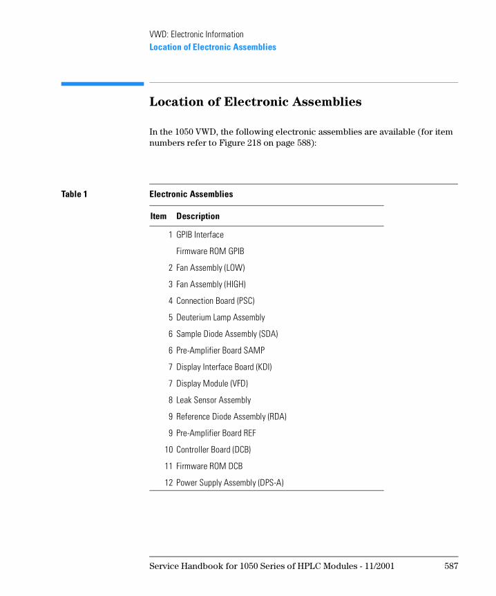
Location of Electronic Assemblies
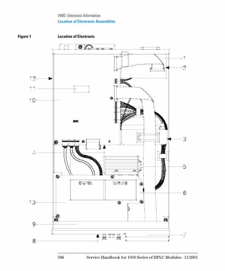
In the 1050 VWD, the following electronic assemblies are available (for item numbers refer to Figure 218 on page 588):
Table 1 Electronic Assemblies
Item Description
1 GPIB Interface
Firmware ROM GPIB
2 Fan Assembly (LOW)
3 Fan Assembly (HIGH)
4 Connection Board (PSC)
5 Deuterium Lamp Assembly
6 Sample Diode Assembly (SDA)
6 Pre-Amplifier Board SAMP
7 Display Interface Board (KDI)
7 Display Module (VFD)
8 Leak Sensor Assembly
9 Reference Diode Assembly (RDA)
9 Pre-Amplifier Board REF
10 Controller Board (DCB)
11 Firmware ROM DCB
12 Power Supply Assembly (DPS-A)
Service Handbook for 1050 Series of HPLC Modules - 11/2001 587
VWD: Electronic InformationLocation of Electronic Assemblies
Figure 1 Location of Electronic
588 Service Handbook for 1050 Series of HPLC Modules - 11/2001
VWD: Electronic InformationInterconnection Diagram
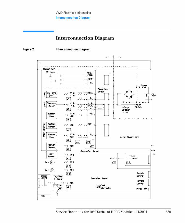
Interconnection Diagram
Figure 2 Interconnection Diagram
Service Handbook for 1050 Series of HPLC Modules - 11/2001 589
VWD: Electronic InformationDetector Controller Board (DCB)
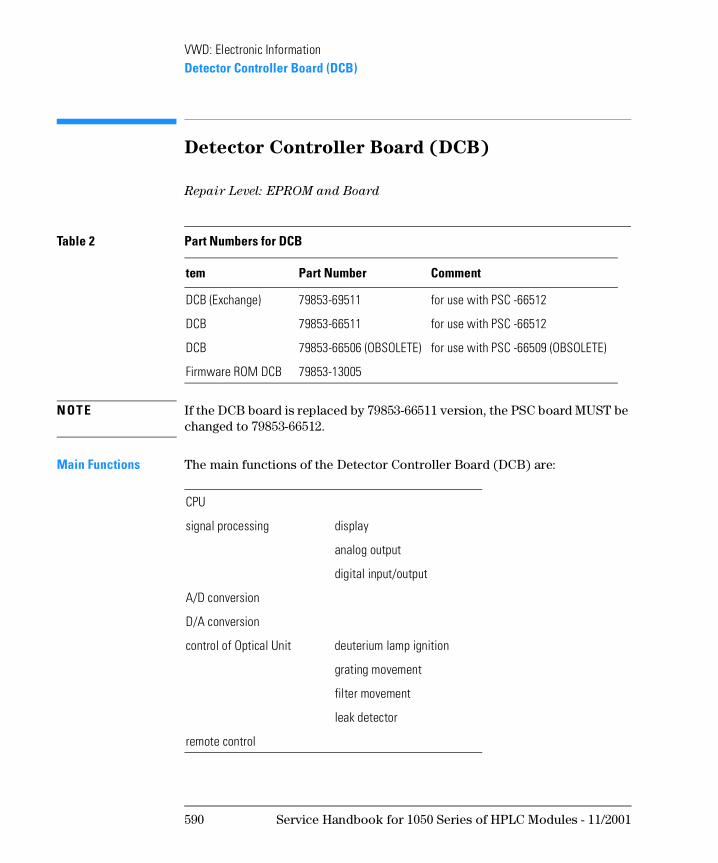
Detector Controller Board (DCB)
Repair Level: EPROM and Board
N OT E If the DCB board is replaced by 79853-66511 version, the PSC board MUST be changed to 79853-66512.
Main Functions The main functions of the Detector Controller Board (DCB) are:
Table 2 Part Numbers for DCB
tem Part Number Comment
DCB (Exchange) 79853-69511 for use with PSC -66512
DCB 79853-66511 for use with PSC -66512
DCB 79853-66506 (OBSOLETE) for use with PSC -66509 (OBSOLETE)
Firmware ROM DCB 79853-13005
CPU
signal processing display
analog output
digital input/output
A/D conversion
D/A conversion
control of Optical Unit deuterium lamp ignition
grating movement
filter movement
leak detector
remote control
590 Service Handbook for 1050 Series of HPLC Modules - 11/2001
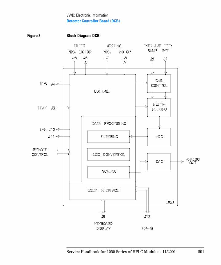
VWD: Electronic InformationDetector Controller Board (DCB)
Figure 3 Block Diagram DCB
Service Handbook for 1050 Series of HPLC Modules - 11/2001 591
VWD: Electronic InformationDetector Controller Board (DCB)
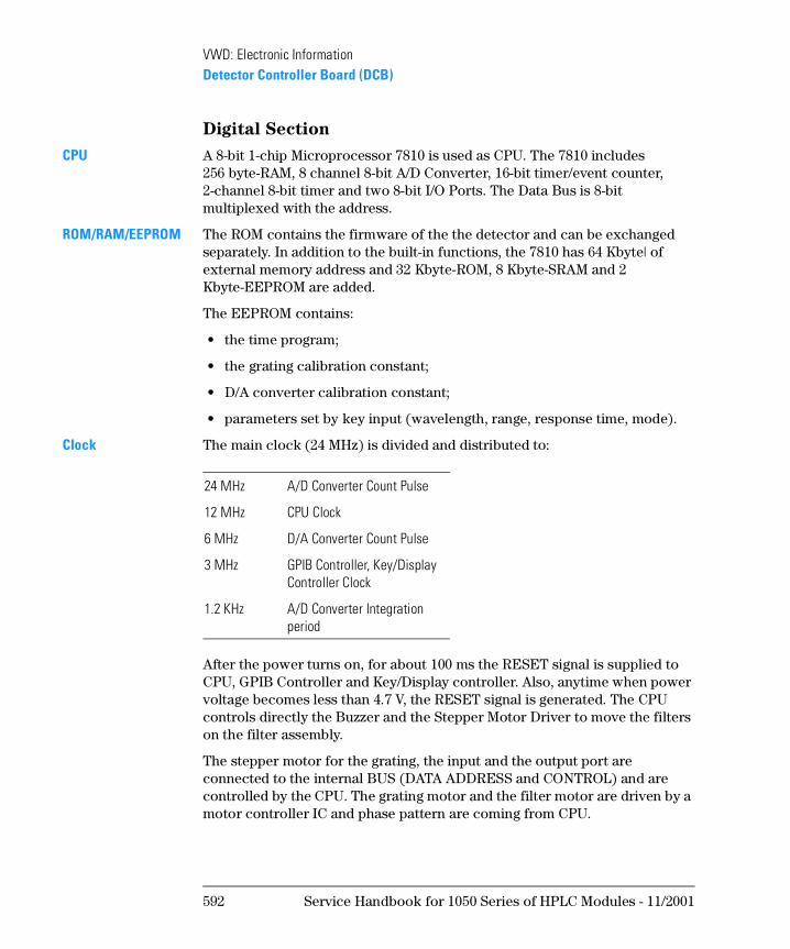
Digital Section
CPU A 8-bit 1-chip Microprocessor 7810 is used as CPU. The 7810 includes 256 byte-RAM, 8 channel 8-bit A/D Converter, 16-bit timer/event counter, 2-channel 8-bit timer and two 8-bit I/O Ports. The Data Bus is 8-bit multiplexed with the address.
ROM/RAM/EEPROM The ROM contains the firmware of the the detector and can be exchanged separately. In addition to the built-in functions, the 7810 has 64 Kbyte| of external memory address and 32 Kbyte-ROM, 8 Kbyte-SRAM and 2 Kbyte-EEPROM are added.
The EEPROM contains:
• the time program;
• the grating calibration constant;
• D/A converter calibration constant;
• parameters set by key input (wavelength, range, response time, mode).
Clock The main clock (24 MHz) is divided and distributed to:
After the power turns on, for about 100 ms the RESET signal is supplied to CPU, GPIB Controller and Key/Display controller. Also, anytime when power voltage becomes less than 4.7 V, the RESET signal is generated. The CPU controls directly the Buzzer and the Stepper Motor Driver to move the filters on the filter assembly.
The stepper motor for the grating, the input and the output port are connected to the internal BUS (DATA ADDRESS and CONTROL) and are controlled by the CPU. The grating motor and the filter motor are driven by a motor controller IC and phase pattern are coming from CPU.
24 MHz A/D Converter Count Pulse
12 MHz CPU Clock
6 MHz D/A Converter Count Pulse
3 MHz GPIB Controller, Key/Display Controller Clock
1.2 KHz A/D Converter Integration period
592 Service Handbook for 1050 Series of HPLC Modules - 11/2001
VWD: Electronic InformationDetector Controller Board (DCB)
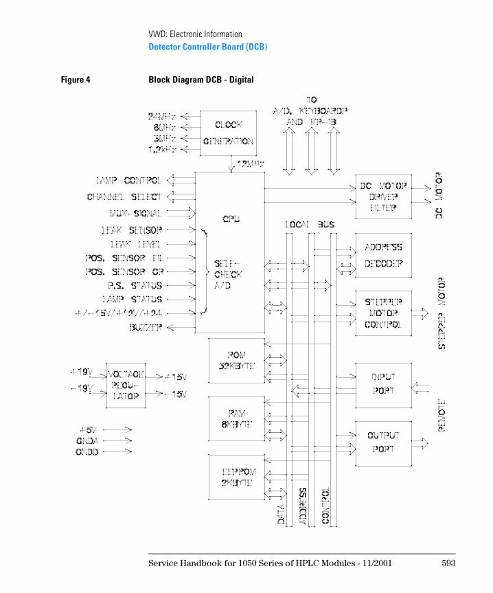
Figure 4 Block Diagram DCB - Digital
Service Handbook for 1050 Series of HPLC Modules - 11/2001 593
VWD: Electronic InformationDetector Controller Board (DCB)
Analog Sections
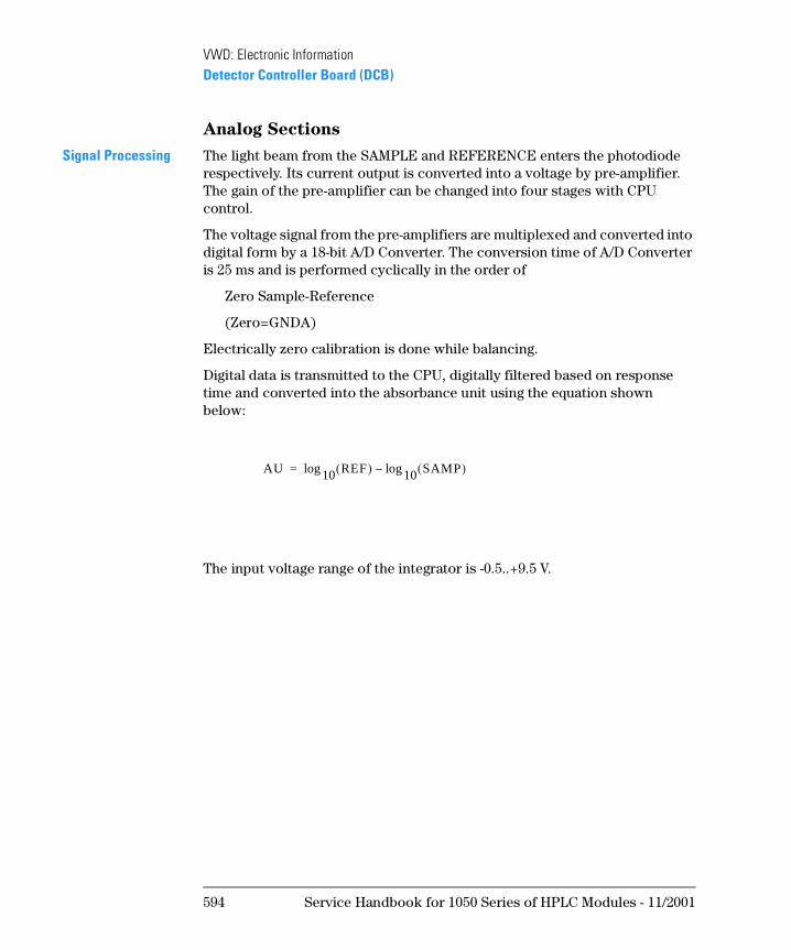
Signal Processing The light beam from the SAMPLE and REFERENCE enters the photodiode respectively. Its current output is converted into a voltage by pre-amplifier. The gain of the pre-amplifier can be changed into four stages with CPU control.
The voltage signal from the pre-amplifiers are multiplexed and converted into digital form by a 18-bit A/D Converter. The conversion time of A/D Converter is 25 ms and is performed cyclically in the order of
Zero Sample-Reference
(Zero=GNDA)
Electrically zero calibration is done while balancing.
Digital data is transmitted to the CPU, digitally filtered based on response time and converted into the absorbance unit using the equation shown below:
The input voltage range of the integrator is -0.5..+9.5 V.
AU 10 REF( )log 10 SAMP( )log–=
594 Service Handbook for 1050 Series of HPLC Modules - 11/2001
VWD: Electronic InformationDetector Controller Board (DCB)
Figure 5 Block Diagram DCB - A/D Conversion
Service Handbook for 1050 Series of HPLC Modules - 11/2001 595
VWD: Electronic InformationDetector Controller Board (DCB)
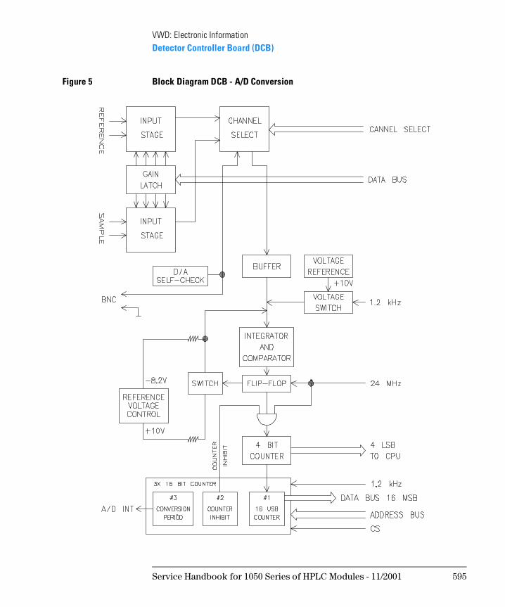
A/D Converter Method for the A/D conversion is feedback type Pulse Width Modulation (PWM).
Figure 6 A/D Converter
Positive or negative reference voltage is alternately added to the integrator. Duty cycles of each reference voltage is controlled by the output of a comparator connected to the output of integrator. Input voltage (U1) is converted to pulse width so that sum of both reference voltages is balanced with the U1. Clock voltage and ±ES control this system and determines the period. The sum of clock voltage in one cycle is set to zero.
Pulse width, which is proportional to input voltage U1, is counted and is converted into a digital output.
The A/D converter has 18 bits resolution with 25 ms conversion time.
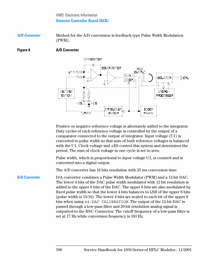
D/A Converter D/A converter combines a Pulse Width Modulator (PWM) and a 12-bit DAC. The lower 4 bits of the DAC pulse width modulated with 12 bit resolution is added to the upper 8 bits of the DAC. The upper 8 bits are also modulated by fixed pulse width so that the lower 4 bits balances to LSB of the upper 8 bits (pulse width is 15/16). The lower 4 bits are scaled to each bit of the upper 8 bits when using 44:DAC CALIBRATION. The output of the 12-bit DAC is passed through a low-pass filter and 20-bit resolution analog signal is outputted to the BNC Connector. The cutoff frequency of a low-pass filter is set at 17 Hz while conversion frequency is 183 Hz.
596 Service Handbook for 1050 Series of HPLC Modules - 11/2001
VWD: Electronic InformationDetector Controller Board (DCB)
Figure 7 D/A Conversion
Signal Output The signal output is classified into three types: Display Out, Analog Out, Digital In/Out.
Display Out The display module receives ASCII codes via Keyboard Interface Board via the Data Bus. On the Display Module, the ASCII code is converted to display code and gives output on fluorescent display with 5 x 7 dots and 16 characters.
Signal (Analog) Out The Signal (Analog) Out is available at a BNC connector at the rear of the instrument. It is generated by 20-bit D/A converter. The conversion cycle of the D/A converter is about 5.5 ms. The output of the D/A converter is filtered by a low-pass filter. The output can be switched to:
Digital In/Out The digital signal is delivered to the GPIB Interface (option) via the Data Bus and is converted into an GPIB signal.
Control of Deuterium Lamp
The deuterium lamp is ignited using Anode Current, Trigger Voltage and Heater Voltage supplied from the Power Supply Unit. The ignition procedures are controlled by the CPU signal. The heater voltage is switched from 2.5 V during ignition to 0 V after ignition.
Full Scale Output Impedance
1 V 1000 Ohm
0.1 V 100 Ohm
Service Handbook for 1050 Series of HPLC Modules - 11/2001 597
VWD: Electronic InformationDetector Controller Board (DCB)
Control of Grating Assembly
The wavelength is set by rotating the grating with a 2-phase stepper motor. The step angle of the stepper motor rotation (1 step angle 3.75°) and is reduced to 1/300 by a gear. The stepper motor is controlled and driven by DCB. The CPU contrls the motor controller IC that drives the motor. Stepper Motor reference position is determined by a plate fitted on the swing arm interrupting a beam of photo interrupter. The output signal of the photo interrupter is read by a 8-bit ADC of the CPU.
Control of Filter Assembly
The rotation of stepper motor controls the insertion of a diffterent filters into the light path (cutoff, holmium, light reduction).
The stepper motor is controlled and driven by DCB. The CPU controls the motor controller IC that drives the motor.
Remote Control The REMOTE connectors communicate start or stop, error and not ready signal inputs and outputs.
For detailed description of remote control refer to the 1050 Service
Handbook, chapter Common Information.
N OT E When the 79853C VWD is used in a system which is connected via remote, the VWD should be switched on as first module. Otherwise it may influence other modules at power on.
Leak Detection The leakage from a flow cell is detected by change of Thermal Radiation Constant of NTC thermistor. Wheatstone bridge is constructed from NTC thermistor and resistors on the DCB. Its supply voltage is varied by controlling 24 V-power with Switching Regulator controller. The supply voltage is controlled to keep the thermistor at about 150 Ohm (150°C) constantly. If leakage occurs and the thermistor is soaked in the leaked liquid, the thermal radiation constant are changed and gives higher supply voltage at both ends of wheatstone bridge. This change is read by the CPU and compensated with ambient temperature.
Error condition is when LS > LL. The values are visable with 33:LEAK TEST.
598 Service Handbook for 1050 Series of HPLC Modules - 11/2001
VWD: Electronic InformationDetector Controller Board (DCB)
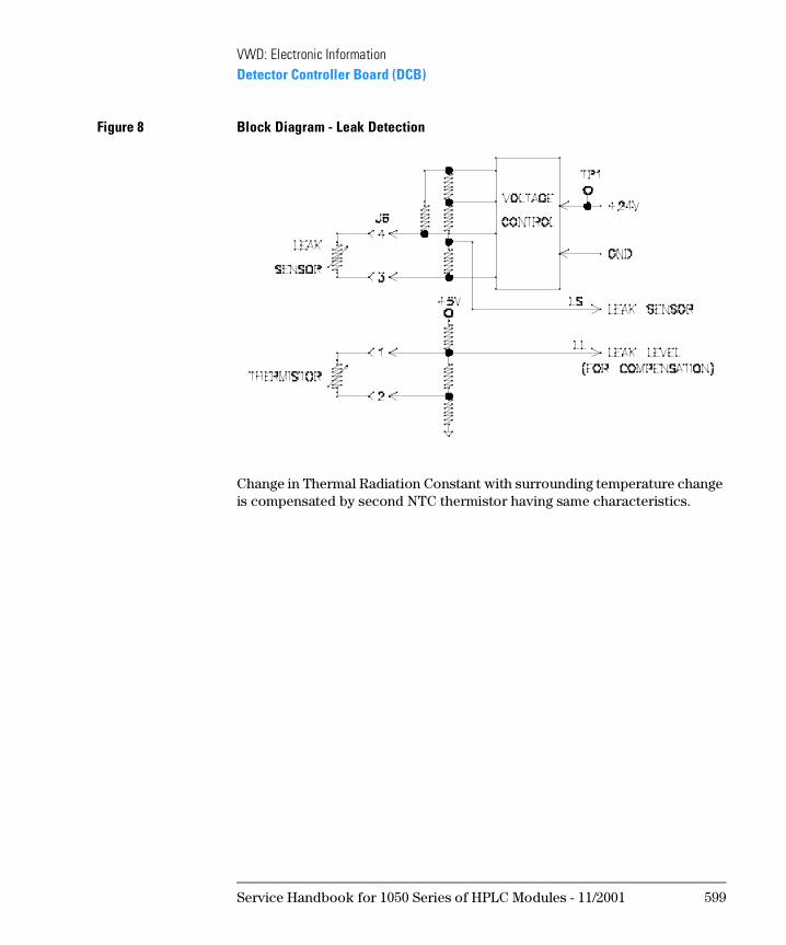
Figure 8 Block Diagram - Leak Detection
Change in Thermal Radiation Constant with surrounding temperature change is compensated by second NTC thermistor having same characteristics.
Service Handbook for 1050 Series of HPLC Modules - 11/2001 599
VWD: Electronic InformationDetector Controller Board (DCB)
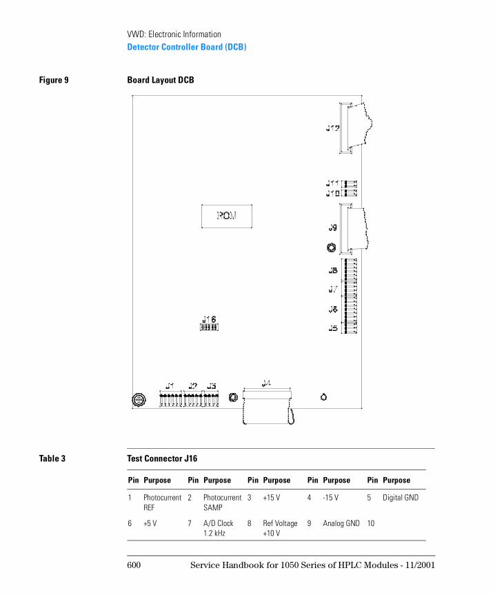
Figure 9 Board Layout DCB
Table 3 Test Connector J16
Pin Purpose Pin Purpose Pin Purpose Pin Purpose Pin Purpose
1 Photocurrent REF
2 Photocurrent SAMP
3 +15 V 4 -15 V 5 Digital GND
6 +5 V 7 A/D Clock1.2 kHz
8 Ref Voltage +10 V
9 Analog GND 10
600 Service Handbook for 1050 Series of HPLC Modules - 11/2001
VWD: Electronic InformationPower Supply (DPS-A)
Power Supply (DPS-A)
Repair Level: Fuses and Exchange DPS-A
For detailed information on the power supply refer the 1050 Service
Handbook, chapter 1050 Common Information.
Lamp Ignition
The heater output made by a series regulator is in the pre-heating status 2.5 V always. After ignition a different output voltage is selected depending on the lamp type used: In the 79853C VWD the heater is switched off after ignition.
Table 4 Part Numbers for DPS-A
Item Part Number
DPS-A (Exchange) 01050-69375
DPS-A (New) 5061-3375
Fuse for 110 V operation 3 A 2110-0003
Fuse for 220 V operation 2 A 2110-0002
Service Handbook for 1050 Series of HPLC Modules - 11/2001 601
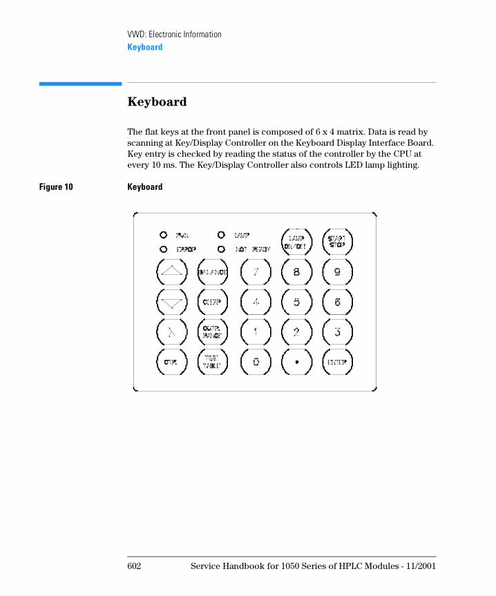
VWD: Electronic InformationKeyboard
Keyboard
The flat keys at the front panel is composed of 6 x 4 matrix. Data is read by scanning at Key/Display Controller on the Keyboard Display Interface Board. Key entry is checked by reading the status of the controller by the CPU at every 10 ms. The Key/Display Controller also controls LED lamp lighting.
Figure 10 Keyboard
602 Service Handbook for 1050 Series of HPLC Modules - 11/2001
VWD: Electronic InformationKeyboard
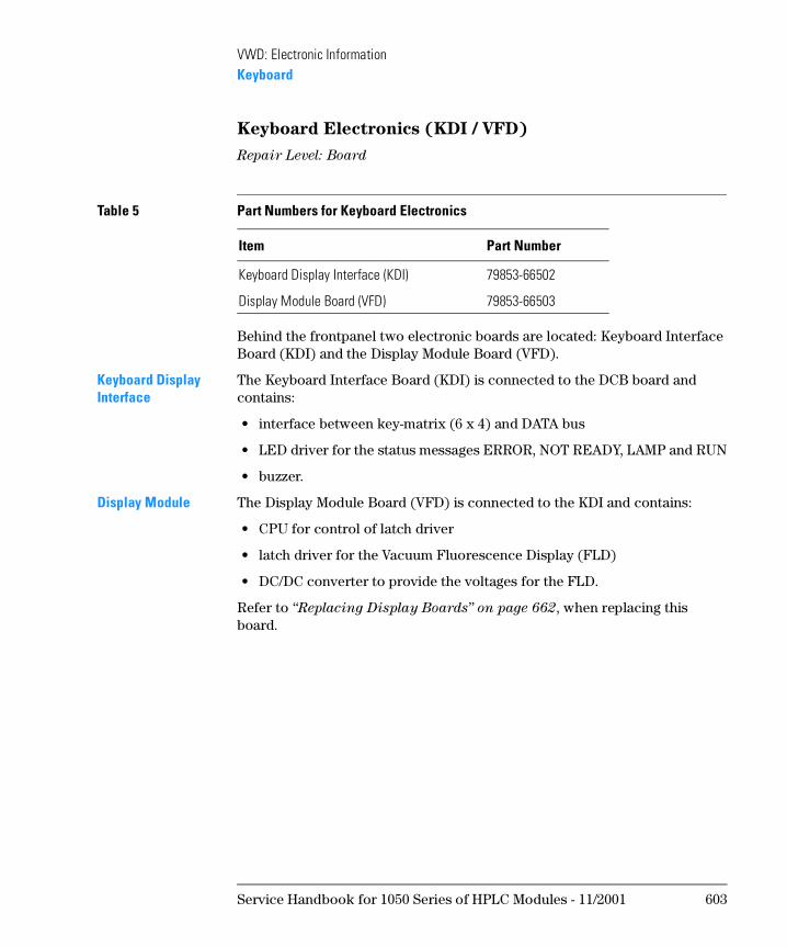
Keyboard Electronics (KDI / VFD)
Repair Level: Board
Behind the frontpanel two electronic boards are located: Keyboard Interface Board (KDI) and the Display Module Board (VFD).
Keyboard Display Interface
The Keyboard Interface Board (KDI) is connected to the DCB board and contains:
• interface between key-matrix (6 x 4) and DATA bus
• LED driver for the status messages ERROR, NOT READY, LAMP and RUN
• buzzer.
Display Module The Display Module Board (VFD) is connected to the KDI and contains:
• CPU for control of latch driver
• latch driver for the Vacuum Fluorescence Display (FLD)
• DC/DC converter to provide the voltages for the FLD.
Refer to “Replacing Display Boards” on page 662, when replacing this board.
Table 5 Part Numbers for Keyboard Electronics
Item Part Number
Keyboard Display Interface (KDI) 79853-66502
Display Module Board (VFD) 79853-66503
Service Handbook for 1050 Series of HPLC Modules - 11/2001 603
VWD: Electronic InformationKeyboard
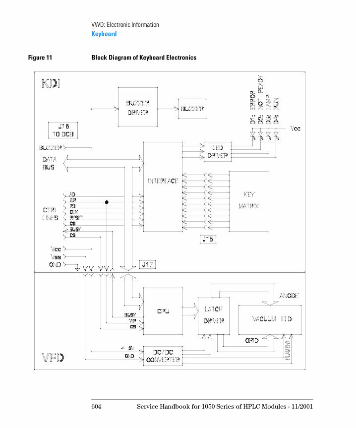
Figure 11 Block Diagram of Keyboard Electronics
604 Service Handbook for 1050 Series of HPLC Modules - 11/2001
VWD: Electronic InformationPre-Amplifier Boards
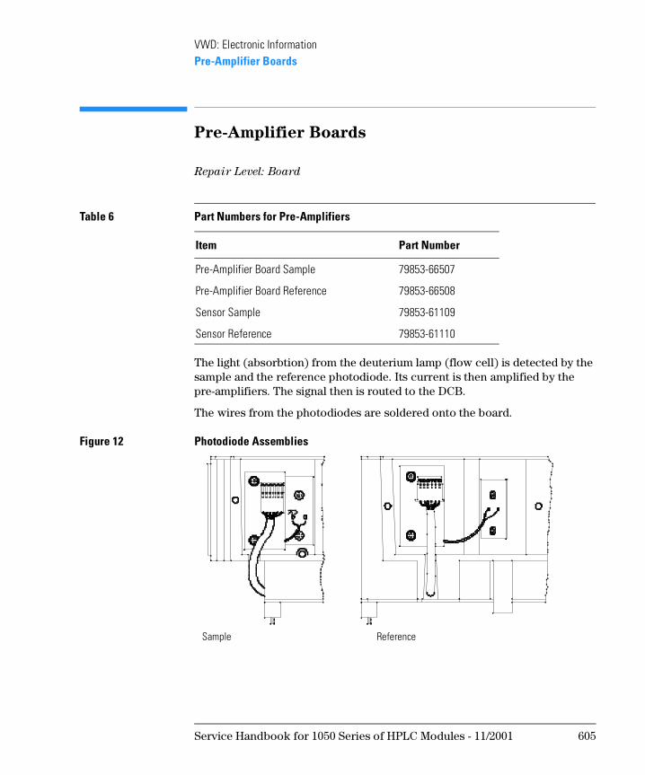
Pre-Amplifier Boards
Repair Level: Board
The light (absorbtion) from the deuterium lamp (flow cell) is detected by the sample and the reference photodiode. Its current is then amplified by the pre-amplifiers. The signal then is routed to the DCB.
The wires from the photodiodes are soldered onto the board.
Figure 12 Photodiode Assemblies
Table 6 Part Numbers for Pre-Amplifiers
Item Part Number
Pre-Amplifier Board Sample 79853-66507
Pre-Amplifier Board Reference 79853-66508
Sensor Sample 79853-61109
Sensor Reference 79853-61110
Sample Reference
Service Handbook for 1050 Series of HPLC Modules - 11/2001 605
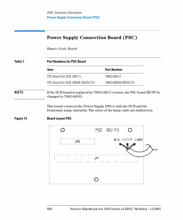
VWD: Electronic InformationPower Supply Connection Board (PSC)
Power Supply Connection Board (PSC)
Repair Level: Board
N OT E If the DCB board is replaced by 79853-66511 version, the PSC board MUST be changed to 79853-66512.
This board connects the Power Supply DPS-A with the DCB and the Deuterium Lamp Assembly. The wires of the lamp cable are soldered in.
Figure 13 Board Layout PSC
Table 7 Part Numbers for PSC Board
Item Part Number
PSC Board (for DCB -66511) 79853-66512
PSC Board (for DCB -66506 OBSOLETE) 79853-66509 OBSOLETE
606 Service Handbook for 1050 Series of HPLC Modules - 11/2001
VWD: Electronic InformationGPIB Communication Interface
GPIB Communication Interface
Repair Level: Board, Firmware
Parallel Interface Dual direction transceiver for data bus between master and slave CPU’s. 8 bit aux code from DCB to GPIB board. 3 bit control code from GPIB board to DCB
Microprocessor Single chip microprocessor with 1 Mbyte address capability, 512 byte internal RAM and 32 I/O ports.
Memories 32 Kbyte of ROM for program memory and 128 Kbyte RAM for the run buffer.
Firmware Description The GPIB board performs all interruption processing from the GPIB controller. DCB and GPIB board communicate with hardware interrupts. Receiving GPIB commands the GPIB board passes them to the DCB with 3 bit control code. This control code shows the kind of bus data such as GPIB commands, error codes or requesting data code and whether the data ended or not. During run or monitor mode the DCB send chromatogram data immediately to the GPIB board with 8 bit aux code. This aux code shows the kind of bus data such as chromatogram data, parameters, time tables, remote line status or GPIB board control code and whether the data ended or not. The GPIB board writes the received data into the run buffer. The GPIB sends out the formatted data adding the start and the end record.
GPIB Address Setting The GPIB address setting is done with a switch (1) at the rear of the GPIB board. The factory setting is ’10’ (position A).
Table 8 Part Numbers for GPIB Interface Board
Item Part Number
GPIB Board (with cable) 79853-68711
GPIB Cable to DCB Board
Firmware ROM GPIB 79853-13004
Service Handbook for 1050 Series of HPLC Modules - 11/2001 607
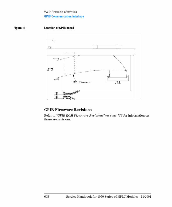
VWD: Electronic InformationGPIB Communication Interface
Figure 14 Location of GPIB board
GPIB Firmware Revisions
Refer to “GPIB ROM Firmware Revisions” on page 733 for information on firmware revisions.
608 Service Handbook for 1050 Series of HPLC Modules - 11/2001
1
1 VWD: Diagnostic &
Troubleshooting Information
This chapter provides information on error messages and diagnostic features of the 1050 Variable Wavelength Detectors
VWD: Diagnostic &
Troubleshooting Information
This section provides information on the
• diagnostic routines
• error messages
• user contol functions
• service control functions
610 Service Handbook for 1050 Series of HPLC Modules - 11/2001
VWD: Diagnostic & Troubleshooting InformationSelf Diagnosis
Self Diagnosis
At power on and after lamp ignition the instrument checks itself for correct operation. In case of malfunctions, error messages will inform the operator on the fault.
During Power On
The following tests are done automatically during power on. They are descibed on the next pages together with the error message:
• Vaccuum Fluorescent display
• ROM and RAM
• Display
• Leak sensor
• Voltages
• A/D Converter
• EEROM Data
• Grating Drive
During Normal Operation
The following tests are done automatically during normal operation:
• for light intensity
• for filter movement
• for leaks
Service Handbook for 1050 Series of HPLC Modules - 11/2001 611
VWD: Diagnostic & Troubleshooting InformationError Messages Before Lamp Ignition
Error Messages Before Lamp Ignition
Error messages may come up during the power on state or the normal operation.
At Power ON
During power on the instrument run automatically through different selftest routines.
If all test are passed, the display shows HP 1050 VWD.
While initializing the CPU checks the response of the Vaccuum Fluorescent Display (VFD) module.
If there is no problem, SELF DIAGNOSIS IN PROGRESS is displayed.
If there is no response from the VFD, the ERROR lamp will light, the buzzer is heard for 2 seconds and is halted.
❏ Check connection DCB/KDI and KDI/VFD module.
❏ Replace VFD Module.
❏ Replace KDI Board.
❏ Replace DCB Board.
❏ Replace DPS.
ROM TEST FAILED The ROM Test calculates the checksum and compares it with a stored value. If a differrence is found, ERROR LED lights, ROM TEST FAILED is displayed and the CPU is halted. Otherwise ROM TEST OK is displayed.
❏ Replace EPROM.
❏ Replace DCB.
RAM TEST FAILED During RAM Test, firstly every RAM address is uniformly written. Then in ascending order, each address is tested for contents and then the data is inverted and written. Then the same procedure is repeated in decending order with the inverted data. This cycle is repeated twice. If an error is found, RAM TEST FAILED is displayed and further operation is prohibited. Otherwise, RAM TEST OK is displayed.
❏ Replace DCB.
612 Service Handbook for 1050 Series of HPLC Modules - 11/2001
VWD: Diagnostic & Troubleshooting InformationError Messages Before Lamp Ignition
Display Test During Display Test every dot on the VFD module is set and you have to confirm it by yourself. If display is black or shows missing dots
❏ Check connection of flat ribbon cable DCB to KDI.
❏ Replace KDI.
L.SENSOR TROUBLE The Leak Sensor Test checks the leak sensor and the leak sensor circuit, but not for a leak resulting from the cell. The voltage applied is measured using built-in 8 bit ADC (A/D Converter) of the CPU as well as temperature compensation voltage from a second thermistor.
If the LS > LL, L.SENSOR TROUBLE is displayed.
The range during turn on should be: LS:0.63..4.06 V and LL:2.82..4.00 V.
❏ Use 33:LEAK S.VOLT to verify the values, (see message LEAK DETECTED.
❏ Check connection of leak sensor to DCB.
❏ Replace leak sensor.
❏ Replace DCB.
POWER FAILURE During Voltage Test this message is displayed if the voltages exceeds the tolerance. If a voltage is not correct, it is displayed for a short moment, for example +24V TROUBLE.
❏ Check voltages using function 34:VOLTAGE TEST:
❏ Replace DCB.
❏ Replace Power Supply.
Table 1 DC Voltages
Voltages Used for
+ 12 V (±1 V) filter and grating motor
- 15 V, + 15 V (±1 V) analog circuits
+ 24 V (± 4.8V) leak sensor, fans
Service Handbook for 1050 Series of HPLC Modules - 11/2001 613
VWD: Diagnostic & Troubleshooting InformationError Messages Before Lamp Ignition
ADC TROUBLE During the A/D Converter Test the 18 bit ADC for photocurrent acquisition is tested with multiplexer channel fixed at analog ground. Pulse count for ground input is measured 20 times and calculate the average and the fluctuations. If the value exceeds the pre-determined value ADC TROUBLE is displayed.
❏ Replace DCB.
EEROM DATA LOST During EEROM Data Test various parameters such as monochrometer parameter and time table are stored in EEROM (Electrically Erasable Read Only Memory) in order to save the value in absence of power. At initializing those values are checked using checksum. If an error is found, EEROM DATA LOST is displayed and default values are set.
Different types of EEROM DATA LOST messages are possible:
EEROM DATA LOST0 The key settable parameters (wavelength, responsetime, and so on) or time time tables are lost. They are replaced by default values.
❏ Re-enter the values.
❏ Replace DCB.
EEROM DATA LOST1 Wavelength parameter (zero order) are lost. They are replaced by default values. The monochromater parameters are differrent for each instrument.
❏ Execute 20:0th CALIB. or enter the 0th order parameter directly using 31:SET WL PARAM.
❏ Execute 45:WL COMPENSATE.
EEROM DATA LOST2 The DAC parameters are lost. The parameters are the scaling factors for each DAC bit and ZERO SPAN factors. The lost parameters are recoverable.
❏ Execute 44:DAC CALIB.
EEROM DATA LOST3 The DAC parameters are lost. The parameters are the offset parameter of the ADC reading for the output of each DAC bit (used for DAC calibration).
N OT E These parameters can be re-written at the factory only.
❏ Perform 41:DAC TEST.
If OK, then leave it as it is.
If NOT OK, then continue.
614 Service Handbook for 1050 Series of HPLC Modules - 11/2001
VWD: Diagnostic & Troubleshooting InformationError Messages Before Lamp Ignition
❏ Perform 44:DAC CALIB. The default values of the offset parameters are taken now.
❏ Perform 41:DAC TEST.
If OK, then leave it as it is.
If NOT OK, then replace DCB board.
WL SET TROUBLE During the initialization of the grating motor position, the motor moves backward to the home position where position sensor detects the limit. If it is not able to detect the limit, WL SET TROUBLE is displayed.
❏ Check connection of position sensor and grating drive motor.
❏ Switch OFF lamp, remove top cover of optical unit to observe movement of grating mirror (changing wavelength).
If grating will not rotate after changing the wavelength, replace DCB or the Grating Driver Assy.
❏ Using 36:GRATING P.S. you can move the grating shaft automatically or stepwise by pressing the down/up key. Normally in the position of about -200 steps, the output voltage of the position sensor will change from LOW to HIGH, detecting the limit position. If the output voltage will never change, the position sensor is defective or the grating drive assembly has a problem and has to be replaced.
Service Handbook for 1050 Series of HPLC Modules - 11/2001 615
VWD: Diagnostic & Troubleshooting InformationError Messages After Lamp Ignition
Error Messages After Lamp Ignition
LAMP ERROR ❏ Check connections of lamp connector, PSC board and DPS to DCB.
❏ Replace lamp, DPS, DCB.
LOW ILLUMINATION Light intensity of deuterium lamp is checked after lamp ignition at the wavelength of 250 nm. If the reference voltage at 250 nm is < 0.6 V, the detector will check the reference voltage at 500 nm and if < 0.12 V, LOW ILLUMINATION will be displayed. In this case the detector will never return to the original wavelength. It will remain at 500 nm.
This test is skipped if WL SET TROUBLE is displayed and unable to set the wavelength.
❏ Check the lamp image on the entrance slit.
If the image does not cover the slit properly, adjust mirror M1.
❏ Check connection to pre-amplifiers.
❏ Replace the lamp for deterioration of lamp.
❏ Replace the mirrors M1 and M2 for deterioration of mirrors.
FILTER ERROR During Filter Test the second order light cutoff filter is tested by inserting it at the wavelength of > 370 nm and measuring the change of light intensity. If an error is found FILTER ERROR is displayed.
This message comes up if
• The reference current at 220 nm is more than 2.00 and at 500 nm more than 1/16 of the value at 220 nm. Then the filter is always off.
• The photocurrent at 220 nm is less than 2.00 and at 500 nm more than 0.04. Then the filter is always ON.
• The reference light beam is focussed far from the reference diode.
❏ Flow cell should be clean and bubble free.
❏ Check connection of filter motor.
❏ Check correct operation of filter with 39:FILTER TEST and photo sensor of filter with 37:FILTER P.S.
❏ Check beam splitter alignment.
616 Service Handbook for 1050 Series of HPLC Modules - 11/2001
VWD: Diagnostic & Troubleshooting InformationError Messages During Normal Operation
Error Messages During Normal Operation
LEAK DETECTED ❏ Enter service mode function 33:LEAK S. VOLT and check leak sensor voltages.
Error condition is when LS > LL. The normal range should be:
❏ If there is no leakage, check the connection leak sensor to DCB.
❏ Replace Leak Detector board.
❏ Replace Leak Sensor.
DATA UNDERFLOW This message may come up only during BALANCING when the sample or referrence voltage is lower than 1 mV.
❏ Check, whether the flow cell is in correct position and the screws are tightened.
❏ Check the connection of pre-amplifier sample to DCB.
❏ Clean cell windows.
❏ Replace photo diode assembly.
❏ Replace DCB.
DATA OVERFLOW This message may come up only during BALANCING when the sample or referrence voltage exceeds 9.4 V.
Check, whether the flow cell is in correct position and the screws are tightened.
Replace DCB.
Table 2 Working Ranges for LS and LL
LS signal LL signal
2.35..2.85 V 2.95..3.45 V
Service Handbook for 1050 Series of HPLC Modules - 11/2001 617
VWD: Diagnostic & Troubleshooting InformationError Messages During Normal Operation
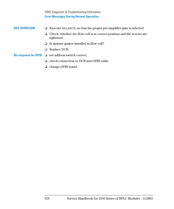
ADC OVERFLOW ❏ Execute BALANCE, so that the proper pre-amplifier gain is selected.
❏ Check, whether the flow cell is in correct position and the screws are tightened.
❏ Is apature gasket installed in flow cell?
❏ Replace DCB.
No response for HPIB ❏ set address switch correct.
❏ check connection to DCB and GPIB cable.
❏ change GPIB board.
618 Service Handbook for 1050 Series of HPLC Modules - 11/2001
VWD: Diagnostic & Troubleshooting InformationError Messages During Use of Control Functions
Error Messages During Use of Control
Functions
CALIB FAILURE • When using 20:0th CALIB. this message may come up because the lamp is turned OFF or to much light reaches the sample diode.
❏ Turn On the lamp.
❏ Reduce light to sample diode.
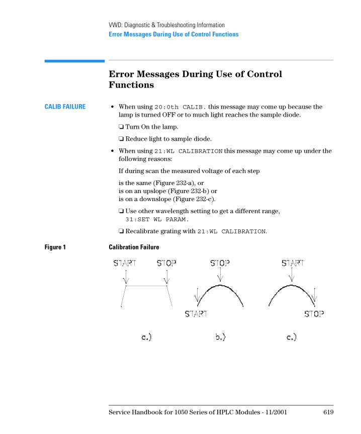
• When using 21:WL CALIBRATION this message may come up under the following reasons:
If during scan the measured voltage of each step
is the same (Figure 232-a), or is on an upslope (Figure 232-b) or is on a downslope (Figure 232-c).
❏ Use other wavelength setting to get a different range, 31:SET WL PARAM.
❏ Recalibrate grating with 21:WL CALIBRATION.
Figure 1 Calibration Failure
Service Handbook for 1050 Series of HPLC Modules - 11/2001 619
VWD: Diagnostic & Troubleshooting InformationUser Control Functions
User Control Functions
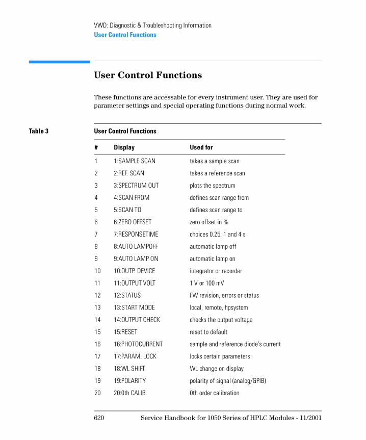
These functions are accessable for every instrument user. They are used for parameter settings and special operating functions during normal work.
Table 3 User Control Functions
# Display Used for
1 1:SAMPLE SCAN takes a sample scan
2 2:REF. SCAN takes a reference scan
3 3:SPECTRUM OUT plots the spectrum
4 4:SCAN FROM defines scan range from
5 5:SCAN TO defines scan range to
6 6:ZERO OFFSET zero offset in %
7 7:RESPONSETIME choices 0.25, 1 and 4 s
8 8:AUTO LAMPOFF automatic lamp off
9 9:AUTO LAMP ON automatic lamp on
10 10:OUTP. DEVICE integrator or recorder
11 11:OUTPUT VOLT 1 V or 100 mV
12 12:STATUS FW revision, errors or status
13 13:START MODE local, remote, hpsystem
14 14:OUTPUT CHECK checks the output voltage
15 15:RESET reset to default
16 16:PHOTOCURRENT sample and reference diode’s current
17 17:PARAM. LOCK locks certain parameters
18 18:WL SHIFT WL change on display
19 19:POLARITY polarity of signal (analog/GPIB)
20 20:0th CALIB. 0th order calibration
620 Service Handbook for 1050 Series of HPLC Modules - 11/2001
VWD: Diagnostic & Troubleshooting InformationUser Control Functions
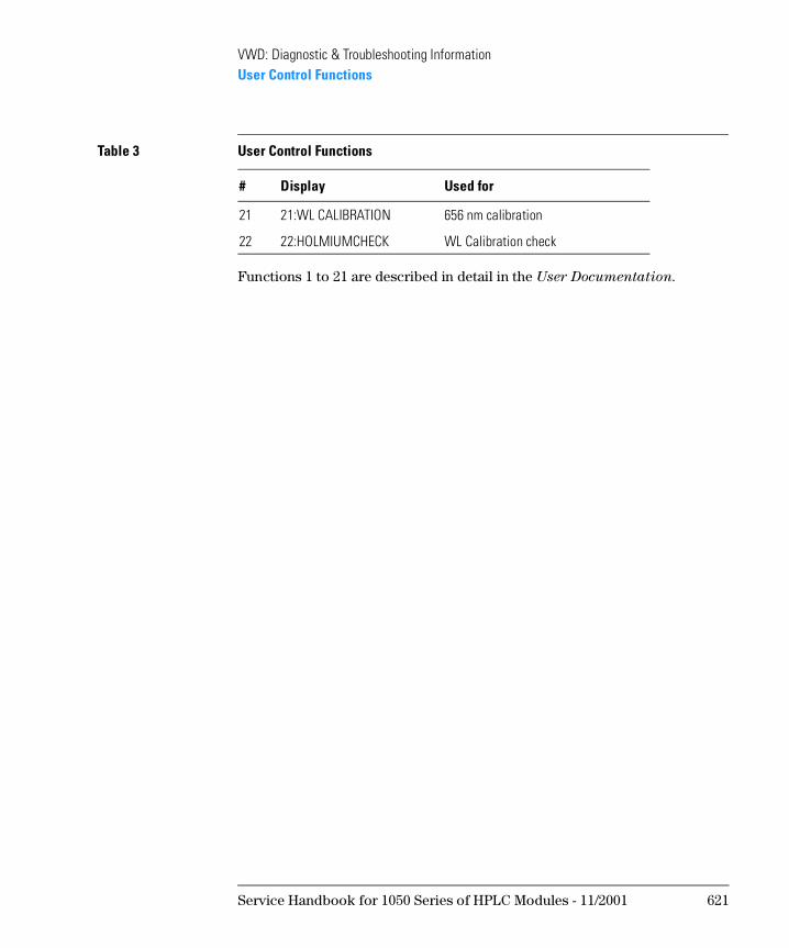
Functions 1 to 21 are described in detail in the User Documentation.
21 21:WL CALIBRATION 656 nm calibration
22 22:HOLMIUMCHECK WL Calibration check
Table 3 User Control Functions
# Display Used for
Service Handbook for 1050 Series of HPLC Modules - 11/2001 621
VWD: Diagnostic & Troubleshooting InformationService Control Functions
Service Control Functions
N OT E These functions are secured by a PASSWORD, because they are normally used by trained Service Engineers. Misuse of certain function may result in a misalignment of the optical path or electronical values.
If the VWD is in service mode, the ERROR status lamp blinks.
If the instrument enters into this mode accidentally, the easiest way to abort from this mode is: TURN OFF the power off the instrument.
Entering the Service Mode
1 Press [CTRL] [3] [0] [ENTER]
2 {30:SERVICE MODE} [ENTER]
3 {Pass Word} [1] [0] [5] [0] [ENTER]
This control function is the entry point for all service control functions. You can enter service control function only through this control function. Select your desired control function using [DOWN] or [UP]. Once you abort from this mode, you have to execute this function again. However if power has not switched off since last entry, you can skip password by just pressing [ENTER].
It is adviced that you will turn-off the power, after you finished using service control functions to avoid the accidental entry to service control mode.
In Table 151 on page 623 all service related functions are listed. Due to different firmware versions and improvements on 79853C VWD, the order of the functions is different.
622 Service Handbook for 1050 Series of HPLC Modules - 11/2001
VWD: Diagnostic & Troubleshooting InformationService Control Functions
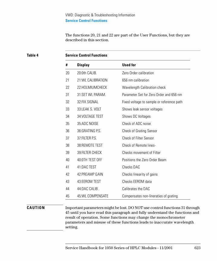
The functions 20, 21 and 22 are part of the User Functions, but they are described in this section.
CA UTI O N Important parameters might be lost. DO NOT use control functions 31 through 45 until you have read this paragraph and fully understand the functions and result of operation. Some functions may change the monochrometer parameters and misuse of these functions leads to inaccurate wavelength setting.
Table 4 Service Control Functions
# Display Used for
20 20:0th CALIB. Zero Order calibration
21 21:WL CALIBRATION 656 nm calibration
22 22:HOLMIUMCHECK Wavelength Calibration check
31 31:SET WL PARAM. Parameter Set for Zero Order and 656 nm
32 32:FIX SIGNAL Fixed voltage to sample or reference path
33 33:LEAK S. VOLT Shows leak sensor voltages
34 34:VOLTAGE TEST Shows DC Voltages
35 35:ADC NOISE Check of ADC noise
36 36:GRATING P.S. Check of Grating Sensor
37 37:FILTER P.S. Check of Filter Sensor
38 38:REMOTE TEST Check of Remote lines-
39 39:FILTER CHECK Checks movement of Filter
40 40:0TH TEST OFF Positions the Zero Order Beam
41 41:DAC TEST Checks DAC
42 42:PREAMP GAIN Checks linearity of gains
43 43:EEROM TEST Checks EEROM data
44 44:DAC CALIB . Calibrates the DAC
45 45:WL COMPENSATE Compensates non-lineraties of grating
Service Handbook for 1050 Series of HPLC Modules - 11/2001 623
VWD: Diagnostic & Troubleshooting InformationService Control Functions
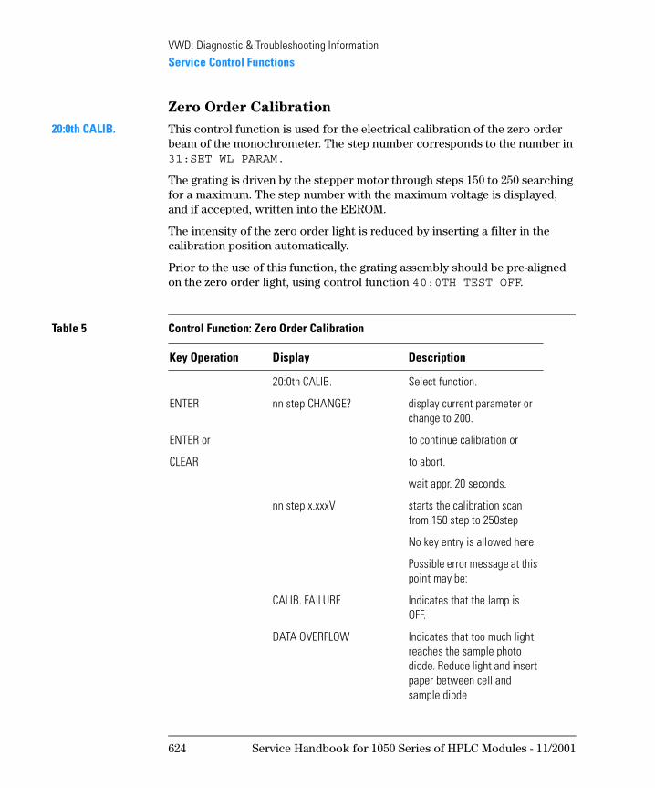
Zero Order Calibration
20:0th CALIB. This control function is used for the electrical calibration of the zero order beam of the monochrometer. The step number corresponds to the number in 31:SET WL PARAM.
The grating is driven by the stepper motor through steps 150 to 250 searching for a maximum. The step number with the maximum voltage is displayed, and if accepted, written into the EEROM.
The intensity of the zero order light is reduced by inserting a filter in the calibration position automatically.
Prior to the use of this function, the grating assembly should be pre-aligned on the zero order light, using control function 40:0TH TEST OFF.
Table 5 Control Function: Zero Order Calibration
Key Operation Display Description
20:0th CALIB. Select function.
ENTER nn step CHANGE? display current parameter or change to 200.
ENTER or to continue calibration or
CLEAR to abort.
wait appr. 20 seconds.
nn step x.xxxV starts the calibration scan from 150 step to 250step
No key entry is allowed here.
Possible error message at this point may be:
CALIB. FAILURE Indicates that the lamp is OFF.
DATA OVERFLOW Indicates that too much light reaches the sample photo diode. Reduce light and insert paper between cell and sample diode
624 Service Handbook for 1050 Series of HPLC Modules - 11/2001
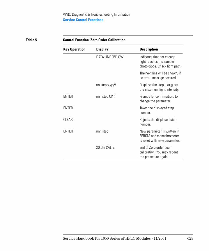
VWD: Diagnostic & Troubleshooting InformationService Control Functions
DATA UNDERFLOW Indicates that not enough light reaches the sample photo diode. Check light path.
The next line will be shown, if no error message occured.
nn step y.yyyV Displays the step that gave the maximum light intensity.
ENTER nnn step OK ? Promps for confirmation, to change the parameter.
ENTER Takes the displayed step number.
CLEAR Rejects the displayed step number.
ENTER nnn step New parameter is written in EEROM and monochrometer is reset with new parameter.
20:0th CALIB. End of Zero order beam calibration. You may repeat the procedure again.
Table 5 Control Function: Zero Order Calibration
Key Operation Display Description
Service Handbook for 1050 Series of HPLC Modules - 11/2001 625
VWD: Diagnostic & Troubleshooting InformationService Control Functions
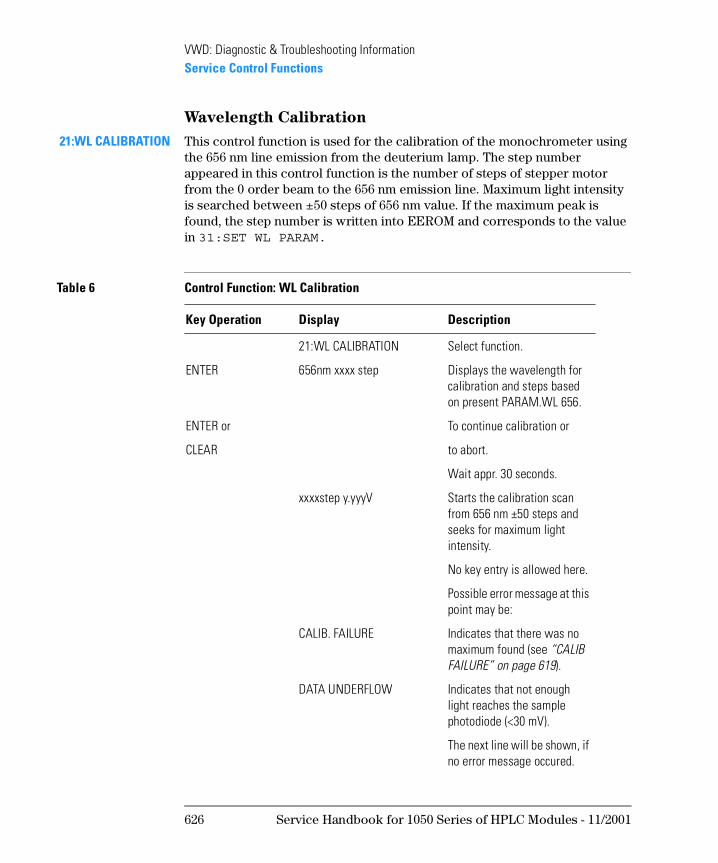
Wavelength Calibration
21:WL CALIBRATION This control function is used for the calibration of the monochrometer using the 656 nm line emission from the deuterium lamp. The step number appeared in this control function is the number of steps of stepper motor from the 0 order beam to the 656 nm emission line. Maximum light intensity is searched between ±50 steps of 656 nm value. If the maximum peak is found, the step number is written into EEROM and corresponds to the value in 31:SET WL PARAM.
Table 6 Control Function: WL Calibration
Key Operation Display Description
21:WL CALIBRATION Select function.
ENTER 656nm xxxx step Displays the wavelength for calibration and steps based on present PARAM.WL 656.
ENTER or To continue calibration or
CLEAR to abort.
Wait appr. 30 seconds.
xxxxstep y.yyyV Starts the calibration scan from 656 nm ±50 steps and seeks for maximum light intensity.
No key entry is allowed here.
Possible error message at this point may be:
CALIB. FAILURE Indicates that there was no maximum found (see “CALIB FAILURE” on page 619).
DATA UNDERFLOW Indicates that not enough light reaches the sample photodiode (<30 mV).
The next line will be shown, if no error message occured.
626 Service Handbook for 1050 Series of HPLC Modules - 11/2001
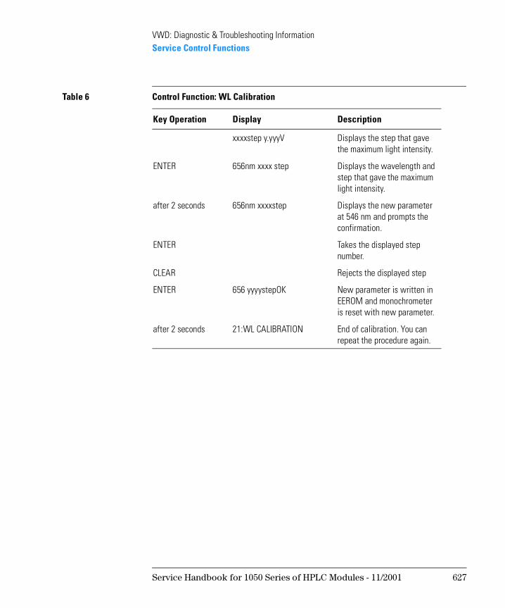
VWD: Diagnostic & Troubleshooting InformationService Control Functions
xxxxstep y.yyyV Displays the step that gave the maximum light intensity.
ENTER 656nm xxxx step Displays the wavelength and step that gave the maximum light intensity.
after 2 seconds 656nm xxxxstep Displays the new parameter at 546 nm and prompts the confirmation.
ENTER Takes the displayed step number.
CLEAR Rejects the displayed step
ENTER 656 yyyystepOK New parameter is written in EEROM and monochrometer is reset with new parameter.
after 2 seconds 21:WL CALIBRATION End of calibration. You can repeat the procedure again.
Table 6 Control Function: WL Calibration
Key Operation Display Description
Service Handbook for 1050 Series of HPLC Modules - 11/2001 627
VWD: Diagnostic & Troubleshooting InformationService Control Functions
Wavelength Calibration Check
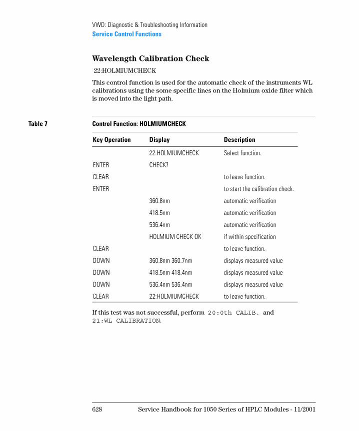
22:HOLMIUMCHECK
This control function is used for the automatic check of the instruments WL calibrations using the some specific lines on the Holmium oxide filter which is moved into the light path.
If this test was not successful, perform 20:0th CALIB. and 21:WL CALIBRATION.
Table 7 Control Function: HOLMIUMCHECK
Key Operation Display Description
22:HOLMIUMCHECK Select function.
ENTER CHECK?
CLEAR to leave function.
ENTER to start the calibration check.
360.8nm automatic verification
418.5nm automatic verification
536.4nm automatic verification
HOLMIUM CHECK OK if within specification
CLEAR to leave function.
DOWN 360.8nm 360.7nm displays measured value
DOWN 418.5nm 418.4nm displays measured value
DOWN 536.4nm 536.4nm displays measured value
CLEAR 22:HOLMIUMCHECK to leave function.
628 Service Handbook for 1050 Series of HPLC Modules - 11/2001
VWD: Diagnostic & Troubleshooting InformationService Control Functions
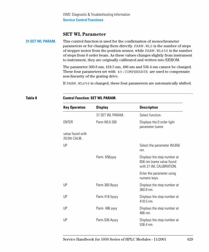
SET WL Parameter
31:SET WL PARAM. This control function is used for the confirmation of monochrometer parameters or for changing them directly. PARM.WL0 is the number of steps of stepper motor from the position sensor, while PARM.WL656 is the number of steps from 0 order beam. As these values changes slightly from instrument to instrument, they are originally calibrated and written into EEROM.
The parameter 360.8 nm, 418.5 nm, 486 nm and 536.4 nm cannot be changed. These four parameters set with 45:COMPENSATE are used to compensate non-linearity of the grating drive.
If PARM.WL656 is changed, these four parameters are automatically shifted.
Table 8 Control Function: SET WL PARAM.
Key Operation Display Description
31:SET WL PARAM. Select function.
ENTER Parm.WL0 200 Displays the 0 order light parameter (same
value found with 20:0th CALIB. .
UP Select the parameter WL656 nm.
Parm. 656yyyy Displays the step number at 656 nm (same value found with 21:WL CALIBRATION.
Enter the parameter using numeric keys.
UP Parm.360.8yyyy Displays the step number at 360.8 nm.
UP Parm.418.5yyyy Displays the step number at 418.5 nm.
UP Parm. 486 yyyy Displays the step number at 486 nm.
UP Parm.536.4yyyy Displays the step number at 536.4 nm.
Service Handbook for 1050 Series of HPLC Modules - 11/2001 629
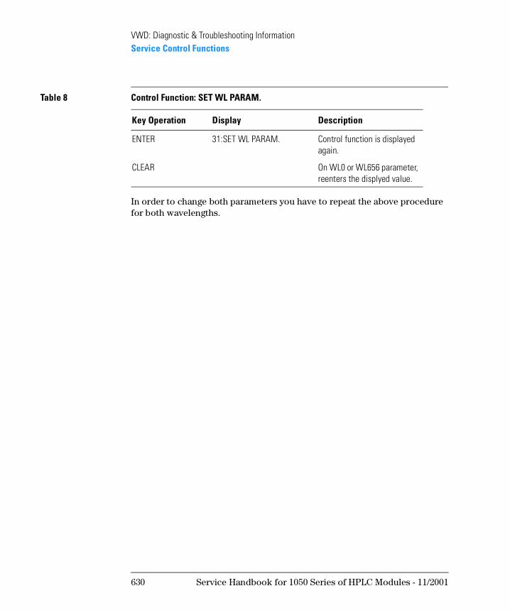
VWD: Diagnostic & Troubleshooting InformationService Control Functions
In order to change both parameters you have to repeat the above procedure for both wavelengths.
ENTER 31:SET WL PARAM. Control function is displayed again.
CLEAR On WL0 or WL656 parameter, reenters the displyed value.
Table 8 Control Function: SET WL PARAM.
Key Operation Display Description
630 Service Handbook for 1050 Series of HPLC Modules - 11/2001
VWD: Diagnostic & Troubleshooting InformationService Control Functions
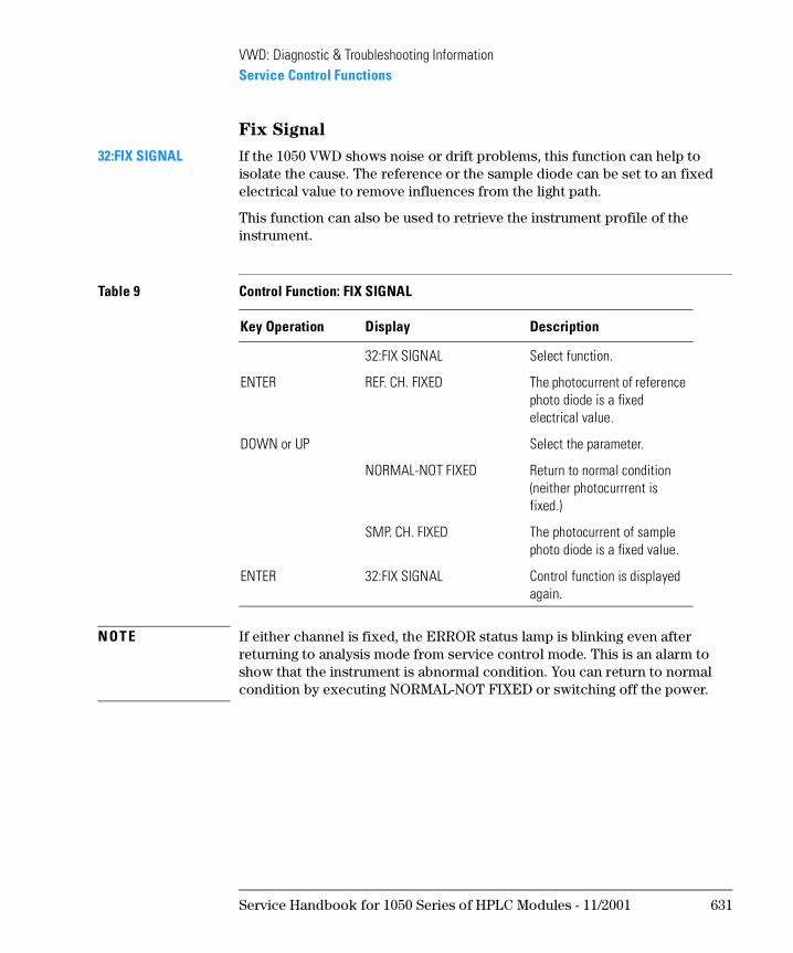
Fix Signal
32:FIX SIGNAL If the 1050 VWD shows noise or drift problems, this function can help to isolate the cause. The reference or the sample diode can be set to an fixed electrical value to remove influences from the light path.
This function can also be used to retrieve the instrument profile of the instrument.
N OT E If either channel is fixed, the ERROR status lamp is blinking even after returning to analysis mode from service control mode. This is an alarm to show that the instrument is abnormal condition. You can return to normal condition by executing NORMAL-NOT FIXED or switching off the power.
Table 9 Control Function: FIX SIGNAL
Key Operation Display Description
32:FIX SIGNAL Select function.
ENTER REF. CH. FIXED The photocurrent of reference photo diode is a fixed electrical value.
DOWN or UP Select the parameter.
NORMAL-NOT FIXED Return to normal condition (neither photocurrrent is fixed.)
SMP. CH. FIXED The photocurrent of sample photo diode is a fixed value.
ENTER 32:FIX SIGNAL Control function is displayed again.
Service Handbook for 1050 Series of HPLC Modules - 11/2001 631
VWD: Diagnostic & Troubleshooting InformationService Control Functions
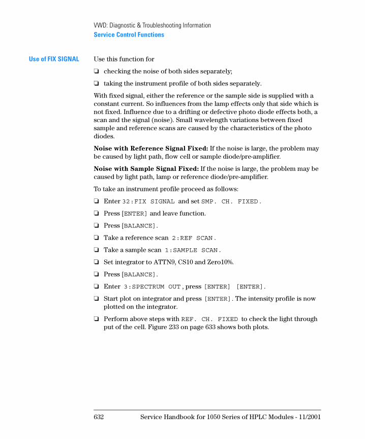
Use of FIX SIGNAL Use this function for
❏ checking the noise of both sides separately;
❏ taking the instrument profile of both sides separately.
With fixed signal, either the reference or the sample side is supplied with a constant current. So influences from the lamp effects only that side which is not fixed. Influence due to a drifting or defective photo diode effects both, a scan and the signal (noise). Small wavelength variations between fixed sample and reference scans are caused by the characteristics of the photo diodes.
Noise with Reference Signal Fixed: If the noise is large, the problem may be caused by light path, flow cell or sample diode/pre-amplifier.
Noise with Sample Signal Fixed: If the noise is large, the problem may be caused by light path, lamp or reference diode/pre-amplifier.
To take an instrument profile proceed as follows:
❏ Enter 32:FIX SIGNAL and set SMP. CH. FIXED .
❏ Press [ENTER] and leave function.
❏ Press [BALANCE].
❏ Take a reference scan 2:REF SCAN .
❏ Take a sample scan 1:SAMPLE SCAN .
❏ Set integrator to ATTN9, CS10 and Zero10%.
❏ Press [BALANCE].
❏ Enter 3:SPECTRUM OUT , press [ENTER] [ENTER].
❏ Start plot on integrator and press [ENTER]. The intensity profile is now plotted on the integrator.
❏ Perform above steps with REF. CH. FIXED to check the light through put of the cell. Figure 233 on page 633 shows both plots.
632 Service Handbook for 1050 Series of HPLC Modules - 11/2001
VWD: Diagnostic & Troubleshooting InformationService Control Functions
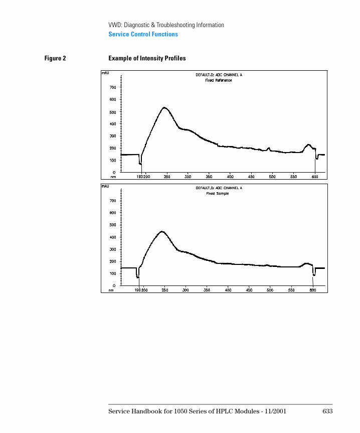
Figure 2 Example of Intensity Profiles
Service Handbook for 1050 Series of HPLC Modules - 11/2001 633
VWD: Diagnostic & Troubleshooting InformationService Control Functions
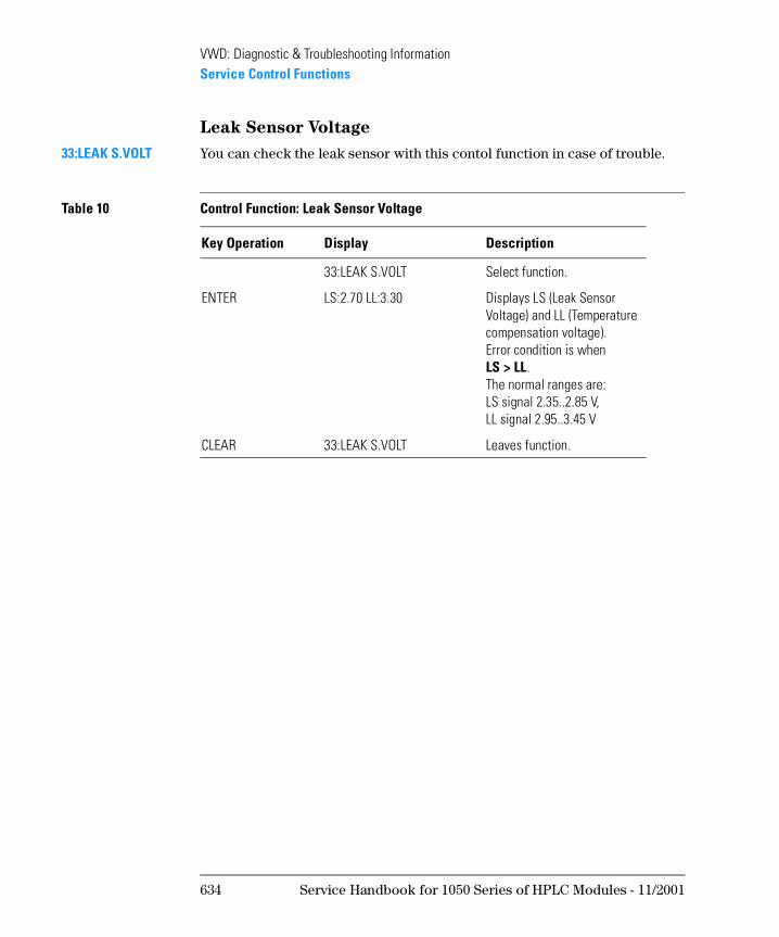
Leak Sensor Voltage
33:LEAK S.VOLT You can check the leak sensor with this contol function in case of trouble.
Table 10 Control Function: Leak Sensor Voltage
Key Operation Display Description
33:LEAK S.VOLT Select function.
ENTER LS:2.70 LL:3.30 Displays LS (Leak Sensor Voltage) and LL (Temperature compensation voltage).Error condition is whenLS > LL. The normal ranges are: LS signal 2.35..2.85 V,LL signal 2.95..3.45 V
CLEAR 33:LEAK S.VOLT Leaves function.
634 Service Handbook for 1050 Series of HPLC Modules - 11/2001
VWD: Diagnostic & Troubleshooting InformationService Control Functions
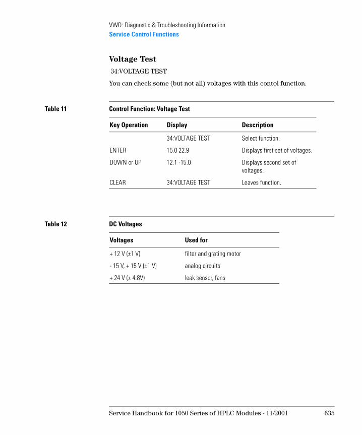
Voltage Test
34:VOLTAGE TEST
You can check some (but not all) voltages with this contol function.
Table 11 Control Function: Voltage Test
Key Operation Display Description
34:VOLTAGE TEST Select function.
ENTER 15.0 22.9 Displays first set of voltages.
DOWN or UP 12.1 -15.0 Displays second set of voltages.
CLEAR 34:VOLTAGE TEST Leaves function.
Table 12 DC Voltages
Voltages Used for
+ 12 V (±1 V) filter and grating motor
- 15 V, + 15 V (±1 V) analog circuits
+ 24 V (± 4.8V) leak sensor, fans
Service Handbook for 1050 Series of HPLC Modules - 11/2001 635

VWD: Diagnostic & Troubleshooting InformationService Control Functions
ADC Noise
35:ADC NOISE The output signal of the ADC noise corresponds to 196 AD counts at the Analog Output with 1 V full scale setting. The ADC noise must be within ±10 counts (±50 mV) over a time of 10 minutes (Figure 234).
Figure 3 ADC Noise
Table 13 Control Function: ADC Noise
Key Operation Display Description
35:ADC NOISE Select function.
ENTER TESTING ADC ADC noise is outputted. Start plotter in ATTN 7, ZERO 50, Chartspeed 1 (on HP 339X)
CLEAR 35:ADC NOISE Leaves function.
636 Service Handbook for 1050 Series of HPLC Modules - 11/2001
VWD: Diagnostic & Troubleshooting InformationService Control Functions
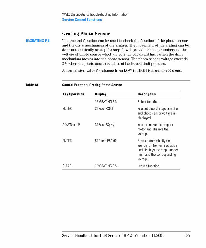
Grating Photo Sensor
36:GRATING P.S. This control function can be used to check the function of the photo sensor and the drive mechanism of the grating. The movement of the grating can be done automatically or step for step. It will provide the step number and the voltage of photo sensor which detects the backward limit when the drive mechanism moves into the photo sensor. The photo sensor voltage exceeds 3 V when the photo sensor reaches at backward limit position.
A normal step value for change from LOW to HIGH is around -200 steps.
Table 14 Control Function: Grating Photo Sensor
Key Operation Display Description
36:GRATING P.S. Select function.
ENTER STPxxx PS0.11 Present step of stepper motor and photo sensor voltage is displayed.
DOWN or UP STPxxx PSy.yy You can move the stepper motor and observe the voltage.
ENTER STP-nnn PS3.90 Starts automatically the search for the home position and displays the step number (nnn) and the corresponding voltage.
CLEAR 36:GRATING P.S. Leaves function.
Service Handbook for 1050 Series of HPLC Modules - 11/2001 637
VWD: Diagnostic & Troubleshooting InformationService Control Functions
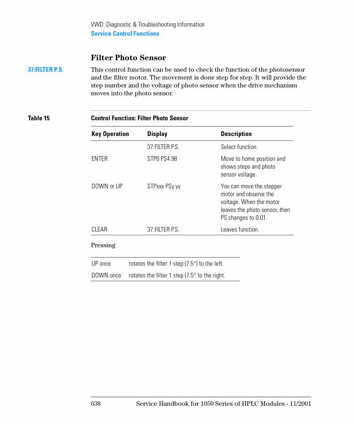
Filter Photo Sensor
37:FILTER P.S. This control function can be used to check the function of the photosensor and the filter motor. The movement is done step for step. It will provide the step number and the voltage of photo sensor when the drive mechanism moves into the photo sensor.
Pressing
Table 15 Control Function: Filter Photo Sensor
Key Operation Display Description
37:FILTER P.S. Select function.
ENTER STP0 PS4.98 Move to home position and shows steps and photo sensor voltage.
DOWN or UP STPxxx PSy.yy You can move the stepper motor and observe the voltage. When the motor leaves the photo sensor, then PS changes to 0.01.
CLEAR 37:FILTER P.S. Leaves function.
UP once rotates the filter 1 step (7.5°) to the left.
DOWN once rotates the filter 1 step (7.5° to the right.
638 Service Handbook for 1050 Series of HPLC Modules - 11/2001
VWD: Diagnostic & Troubleshooting InformationService Control Functions
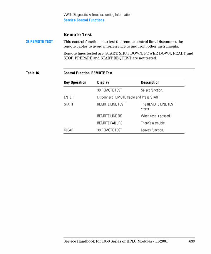
Remote Test
38:REMOTE TEST This control function is to test the remote control line. Disconnect the remote cables to avoid interferrence to and from other instruments.
Remote lines tested are: START, SHUT DOWN, POWER DOWN, READY and STOP. PREPARE and START REQUEST are not tested.
Table 16 Control Function: REMOTE Test
Key Operation Display Description
38:REMOTE TEST Select function.
ENTER Disconnect REMOTE Cable and Press START
START REMOTE LINE TEST The REMOTE LINE TEST starts.
REMOTE LINE OK When test is passed.
REMOTE FAILURE There’s a trouble.
CLEAR 38:REMOTE TEST Leaves function.
Service Handbook for 1050 Series of HPLC Modules - 11/2001 639
VWD: Diagnostic & Troubleshooting InformationService Control Functions
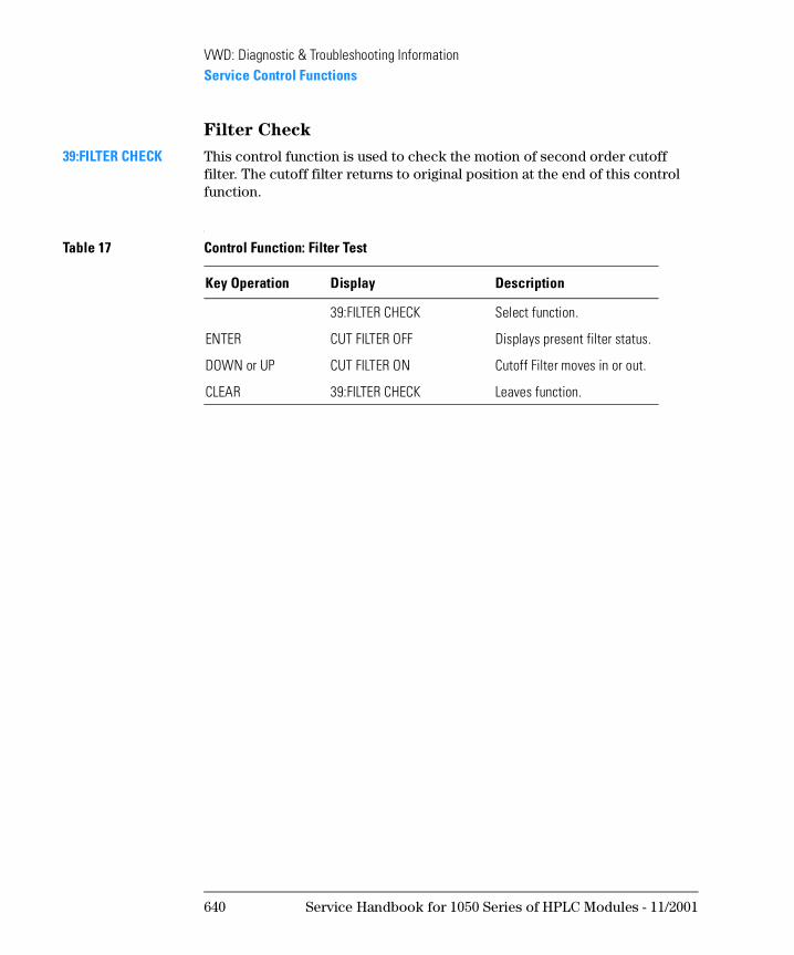
Filter Check
39:FILTER CHECK This control function is used to check the motion of second order cutoff filter. The cutoff filter returns to original position at the end of this control function.
Table 17 Control Function: Filter Test
Key Operation Display Description
39:FILTER CHECK Select function.
ENTER CUT FILTER OFF Displays present filter status.
DOWN or UP CUT FILTER ON Cutoff Filter moves in or out.
CLEAR 39:FILTER CHECK Leaves function.
640 Service Handbook for 1050 Series of HPLC Modules - 11/2001
VWD: Diagnostic & Troubleshooting InformationService Control Functions
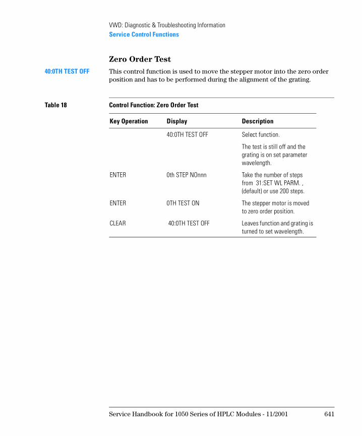
Zero Order Test
40:0TH TEST OFF This control function is used to move the stepper motor into the zero order position and has to be performed during the alignment of the grating.
Table 18 Control Function: Zero Order Test
Key Operation Display Description
40:0TH TEST OFF Select function.
The test is still off and the grating is on set parameter wavelength.
ENTER 0th STEP NOnnn Take the number of steps from 31:SET WL PARM. , (default) or use 200 steps.
ENTER 0TH TEST ON The stepper motor is moved to zero order position.
CLEAR 40:0TH TEST OFF Leaves function and grating is turned to set wavelength.
Service Handbook for 1050 Series of HPLC Modules - 11/2001 641
VWD: Diagnostic & Troubleshooting InformationService Control Functions
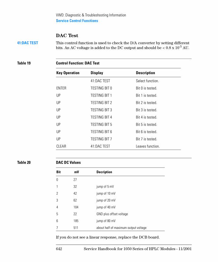
DAC Test
41:DAC TEST This control function is used to check the D/A converter by setting different bits. An AC voltage is added to the DC output and should be < 0.8 x 10⁻⁵ AU.
If you do not see a linear response, replace the DCB board.
Table 19 Control Function: DAC Test
Key Operation Display Description
41:DAC TEST Select function.
ENTER TESTING BIT 0 Bit 0 is tested.
UP TESTING BIT 1 Bit 1 is tested.
UP TESTING BIT 2 Bit 2 is tested.
UP TESTING BIT 3 Bit 3 is tested.
UP TESTING BIT 4 Bit 4 is tested.
UP TESTING BIT 5 Bit 5 is tested.
UP TESTING BIT 6 Bit 6 is tested.
UP TESTING BIT 7 Bit 7 is tested.
CLEAR 41:DAC TEST Leaves function.
Table 20 DAC DC Values
Bit mV Decription
0 27
1 32 jump of 5 mV
2 42 jump of 10 mV
3 62 jump of 20 mV
4 104 jump of 40 mV
5 22 GND plus offset voltage
6 185 jump of 80 mV
7 511 about half of maximum output voltage
642 Service Handbook for 1050 Series of HPLC Modules - 11/2001
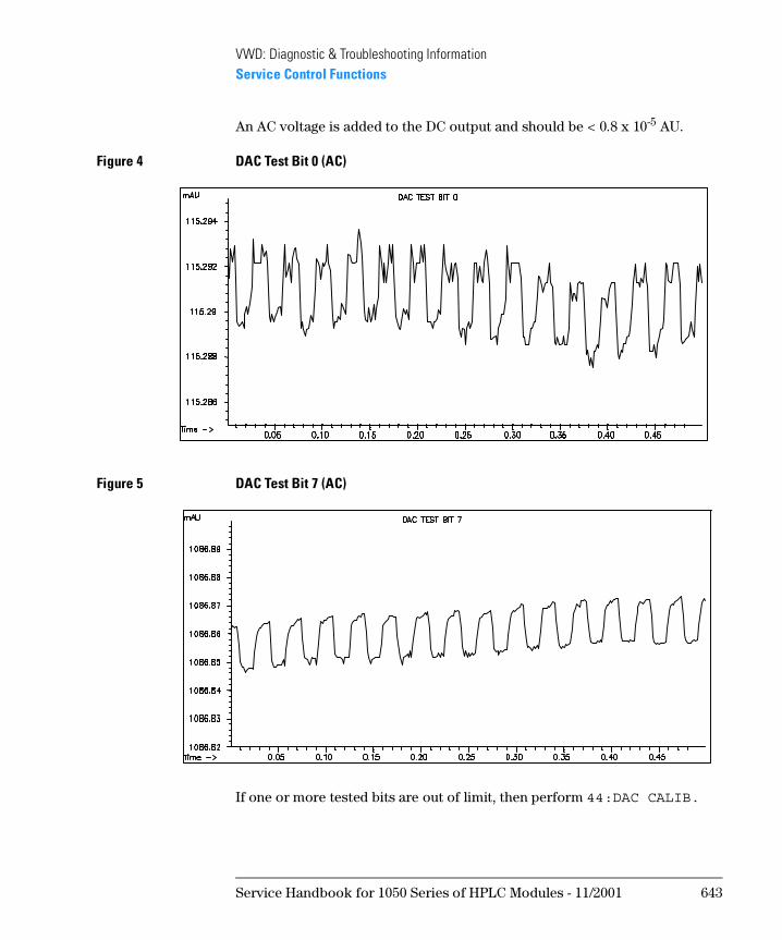
VWD: Diagnostic & Troubleshooting InformationService Control Functions
An AC voltage is added to the DC output and should be < 0.8 x 10⁻⁵ AU.
Figure 4 DAC Test Bit 0 (AC)
Figure 5 DAC Test Bit 7 (AC)
If one or more tested bits are out of limit, then perform 44:DAC CALIB.
Service Handbook for 1050 Series of HPLC Modules - 11/2001 643
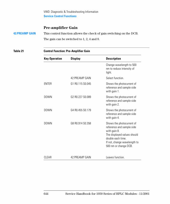
VWD: Diagnostic & Troubleshooting InformationService Control Functions
Pre-amplifier Gain
42:PREAMP GAIN This control function allows the check of gain switching on the DCB.
The gain can be switched to 1, 2, 4 and 8.
Table 21 Control Function: Pre-Amplifier Gain
Key Operation Display Description
Change wavelength to 500 nm to reduce intensity of light.
42:PREAMP GAIN Select function.
ENTER G1 R0.115 S0.045 Shows the photocurrent of reference and sample side with gain 1.
DOWN G2 R0.227 S0.089 Shows the photocurrent of reference and sample side with gain 2.
DOWN G4 R0.455 S0.179 Shows the photocurrent of reference and sample side with gain 4.
DOWN G8 R0.914 S0.358 Shows the photocurrent of reference and sample side with gain 8. The displayed values should double each time.If not, change wavelength to 500 nm or change DCB.
CLEAR 42:PREAMP GAIN Leaves function.
644 Service Handbook for 1050 Series of HPLC Modules - 11/2001
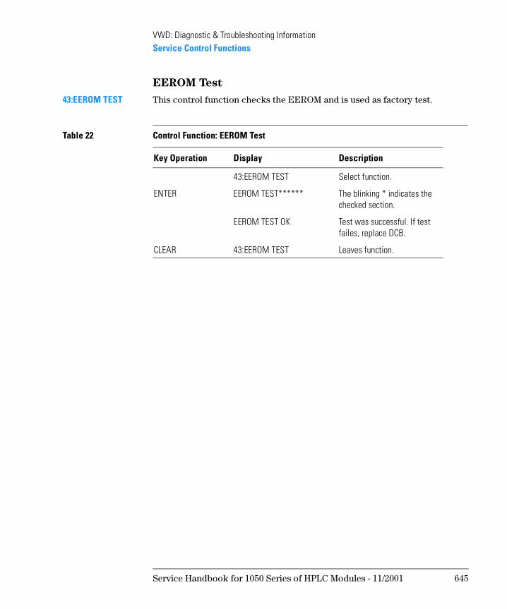
VWD: Diagnostic & Troubleshooting InformationService Control Functions
EEROM Test
43:EEROM TEST This control function checks the EEROM and is used as factory test.
Table 22 Control Function: EEROM Test
Key Operation Display Description
43:EEROM TEST Select function.
ENTER EEROM TEST****** The blinking * indicates the checked section.
EEROM TEST OK Test was successful. If test failes, replace DCB.
CLEAR 43:EEROM TEST Leaves function.
Service Handbook for 1050 Series of HPLC Modules - 11/2001 645
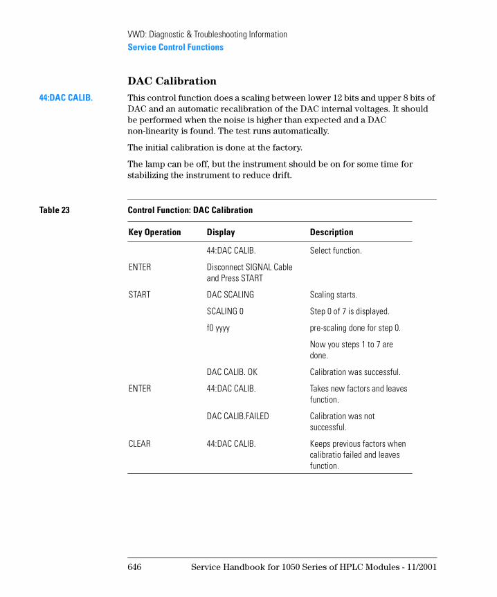
VWD: Diagnostic & Troubleshooting InformationService Control Functions
DAC Calibration
44:DAC CALIB. This control function does a scaling between lower 12 bits and upper 8 bits of DAC and an automatic recalibration of the DAC internal voltages. It should be performed when the noise is higher than expected and a DAC non-linearity is found. The test runs automatically.
The initial calibration is done at the factory.
The lamp can be off, but the instrument should be on for some time for stabilizing the instrument to reduce drift.
Table 23 Control Function: DAC Calibration
Key Operation Display Description
44:DAC CALIB. Select function.
ENTER Disconnect SIGNAL Cable and Press START
START DAC SCALING Scaling starts.
SCALING 0 Step 0 of 7 is displayed.
f0 yyyy pre-scaling done for step 0.
Now you steps 1 to 7 are done.
DAC CALIB. OK Calibration was successful.
ENTER 44:DAC CALIB. Takes new factors and leaves function.
DAC CALIB.FAILED Calibration was not successful.
CLEAR 44:DAC CALIB. Keeps previous factors when calibratio failed and leaves function.
646 Service Handbook for 1050 Series of HPLC Modules - 11/2001
VWD: Diagnostic & Troubleshooting InformationService Control Functions
Wavelength Compensation
45:WL COMPENSATE This control function is used to compensate non-lineratity of the grating drive.
N OT E If the grating motor or the grating has been replaced or moved, this function MUST be executed.
During this test, the flow cell should be empty (no windows) or clean filled with water or methanol (no air bubbles). Absorption in the flow cell causes an error.
• First step is to search for the 656 nm line emission of the deuterium lamp within a window of ±50 steps.
• Then the processor sets the ideal (linear) steps for four interpolative points, 360.8 nm, 418.5 nm, 486 nm and 536.4 nm.
360.8 nm and 418.5 nm are absorption points of the holmium oxide spectra. 536.4 nm is a line emission from the deuterium lamp.
• Next, it scans each ideal interpolative point (±25 steps) as reference.
• Then the holmium oxide filter is inserted and it scans again for the three absorption points of holmium oxide spectra (±25 steps).
• If all found values are in limit, then the parameters are written into EEROM (visable with 31:SET WL PARAM.).
Table 24 Control Function: WL Compenstation
Key Operation Display Description
45:WL COMPENSATE Select function.
ENTER PARAM. CHANGE ?
ENTER to continue calibration
CLEAR to abort calibration
XXXstep y.yyyV displays steps and voltage during calibration
CALIB. FINISHED new parameter, written into EEROM.
Service Handbook for 1050 Series of HPLC Modules - 11/2001 647
VWD: Diagnostic & Troubleshooting InformationService Control Functions
ENTER 45:WL COMPENSATE Takes new factors and leaves function.
WL CALIB. FAILURE one or more peaks could not be found with ±25 steps. Parameters are set to previous values.
CLEAR 45:WL COMPENSATE Keeps previous factors when calibration failed and leaves function.
Table 24 Control Function: WL Compenstation
Key Operation Display Description
648 Service Handbook for 1050 Series of HPLC Modules - 11/2001
1
1 VWD: Maintenance Information
This chapter provides provide procedures for service and maintenance of the 1050 Variable Wavelength Detectors
VWD: Maintenance Information
N OT E The information in this chapter is based on the original optical unit (version “C”). In June 1995 this optical was replaced by the enhanced version “D” to overcome baseline stability problems in unstable environments.
For details on this “D” version refer to section Enhanced Optical Unit Information “VWD: Enhanced Optical Unit Information” on page 705.
Warnings
WA RN I N G Dangerous voltage is present in the cabinet, though it is covered and
insulated. DO NOT TOUCH PARTS unless they are specified in the
procedure.
Be careful when you have to work in the optical unit. The lamp housing
is hot.
Be sure to wear a pair of safety or sun glasses. Since the deuterium
lamp emits intensive ultraviolet light, it is dangerous to perform
optical alignment without eye protection. Be careful not to expose
your eyes directly to the light coming from the lamp.
650 Service Handbook for 1050 Series of HPLC Modules - 11/2001
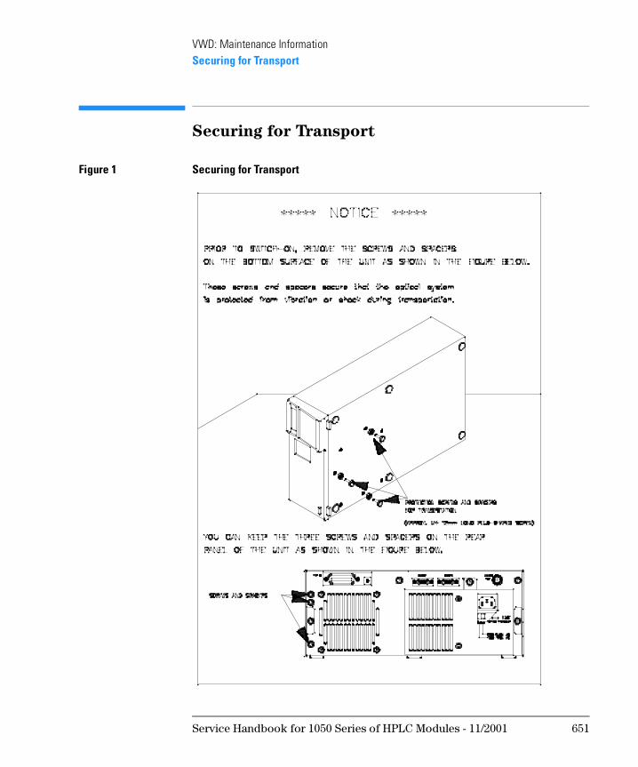
VWD: Maintenance InformationSecuring for Transport
Securing for Transport
Figure 1 Securing for Transport
Service Handbook for 1050 Series of HPLC Modules - 11/2001 651
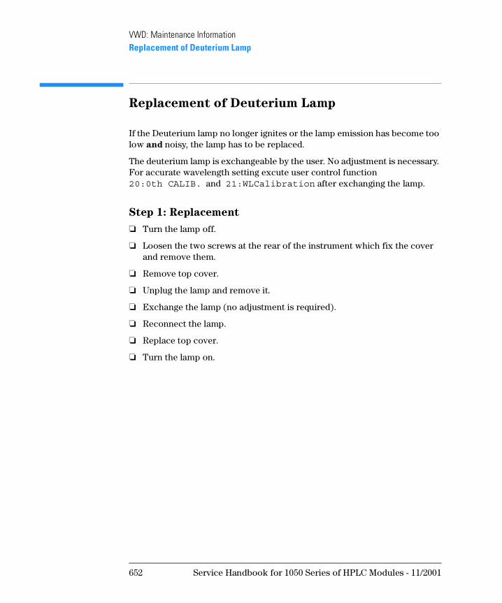
VWD: Maintenance InformationReplacement of Deuterium Lamp
Replacement of Deuterium Lamp
If the Deuterium lamp no longer ignites or the lamp emission has become too low and noisy, the lamp has to be replaced.
The deuterium lamp is exchangeable by the user. No adjustment is necessary. For accurate wavelength setting excute user control function 20:0th CALIB. and 21:WLCalibration after exchanging the lamp.
Step 1: Replacement
❏ Turn the lamp off.
❏ Loosen the two screws at the rear of the instrument which fix the cover and remove them.
❏ Remove top cover.
❏ Unplug the lamp and remove it.
❏ Exchange the lamp (no adjustment is required).
❏ Reconnect the lamp.
❏ Replace top cover.
❏ Turn the lamp on.
652 Service Handbook for 1050 Series of HPLC Modules - 11/2001
VWD: Maintenance InformationReplacement of Deuterium Lamp
Step 2: 0th Order Calibration
The instrument scans for the maximum of the zero-order light.
During 0th order calibration a filter for reducing light intensity to prevent ADC data overflow will be inserted automatically.
Select control function 20:0th CALIB.
If CALIB. FAILURE occurs, press [CLEAR] to keep the old value and to leave function.
[ENTER] enters function
200step CHANGE? displays the current parameter
[ENTER] or [CLEAR] to continue or to abort
150step 0.000V instrument scans now for maximum from step 150 to 250
201step X.XXXV maximum when calibration successfully finished, press [ENTER]
201 step OK ? press [ENTER] to keep the new value and to leave function
Service Handbook for 1050 Series of HPLC Modules - 11/2001 653
VWD: Maintenance InformationReplacement of Deuterium Lamp
Step 3: WL CALIBRATION
The instrument scans for maximum light intensity of 656 nm line spectrum of deuterium lamp.
Enter control function 21:WL CALIBRATION.
If CALIB. FAILURE occurs, press [CLEAR] to keep the old value and to leave function.
[ENTER] enters function
656nm 1900step displays the current parameter.
[ENTER] or [CLEAR] to continue or to abort
1875step 0.000V the instrument scans now for for maximum for 100 steps
1902step X.XXXV maximum when calibration successfully finished, press [ENTER]
656 1902stepOK? press [ENTER] to keep the new value and to leave function.
654 Service Handbook for 1050 Series of HPLC Modules - 11/2001
VWD: Maintenance InformationFlow Cell Maintenance
Flow Cell Maintenance
To replace or clean certain parts of the flow cell you should have a clean working area.
Refer to “Standard Flow Cell “C” (SST/Ti)” on page 693 and the following pages for detailed flow cell schematics.
Flow Cell Maintenance Kits
There are several maintenance kits available with replacement parts for the flow cells.
For details see“Standard Flow Cell “C” (SST/Ti)” on page 693 and the following pages.
Replacing Cell Parts
For the detailed procedures refer to the Operating Manual.
❏ Remove flow cell.
❏ Unscrew the cell screw using a 6 mm hexagon wrench, see Figure 238 on page 656, item 1.
❏ Remove inner parts carefully and place them in the correct order in front of you.
❏ Replace window, gaskets or other parts as needed.
N OT E Once a gasket has been compressed or spoiled on the surface, DO NOT use it again. A used gasket may cause leakage.
❏ Insert all parts in the correct order.
❏ Tighten the cell screw.
❏ Perform a “Leak Test” on page 657.
Service Handbook for 1050 Series of HPLC Modules - 11/2001 655
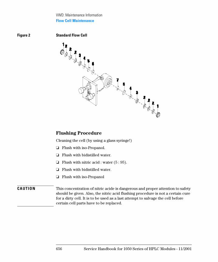
VWD: Maintenance InformationFlow Cell Maintenance
Figure 2 Standard Flow Cell
Flushing Procedure
Cleaning the cell (by using a glass syringe!)
❏ Flush with iso-Propanol.
❏ Flush with bidistilled water.
❏ Flush with nitric acid : water (5 : 95).
❏ Flush with bidistilled water.
❏ Flush with iso-Propanol
CA UTI O N This concentration of nitric acide is dangerous and proper attention to safety should be given. Also, the nitric acid flushing procedure is not a certain cure for a dirty cell. It is to be used as a last attempt to salvage the cell before certain cell parts have to be replaced.
656 Service Handbook for 1050 Series of HPLC Modules - 11/2001
VWD: Maintenance InformationFlow Cell Maintenance
Leak Test
Remove the flow cell and connect the outlet tubing of the flow cell directly to the pump. Then flow an appropriate solvent (for example Isopropanol) at 10 ml/min. After several minutes check the cell visually. If it is necessary to check it for higher pressure, put an appropriate stainless steel tubing which can build up a back-pressure.
CA UTI O N DO NOT apply higher back pressure to the flow cell than maximum pressure of the flow cell.
Table 1 Pressure Rating on Flow Cells
Type Pressure
Standard Flow Cell 40 bar
Ultra High-Pressure Cell 400 bar
Preparative Flow Cell 40 bar
Semi-Micro Flow Cell 40 bar
Service Handbook for 1050 Series of HPLC Modules - 11/2001 657
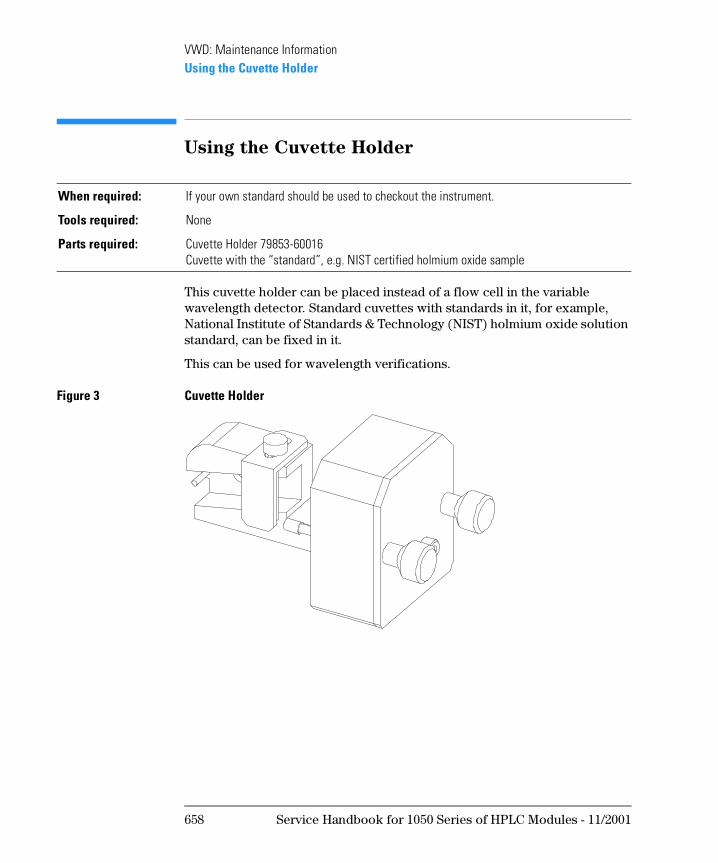
VWD: Maintenance InformationUsing the Cuvette Holder
Using the Cuvette Holder
This cuvette holder can be placed instead of a flow cell in the variable wavelength detector. Standard cuvettes with standards in it, for example, National Institute of Standards & Technology (NIST) holmium oxide solution standard, can be fixed in it.
This can be used for wavelength verifications.
Figure 3 Cuvette Holder
When required: If your own standard should be used to checkout the instrument.
Tools required: None
Parts required: Cuvette Holder 79853-60016Cuvette with the “standard”, e.g. NIST certified holmium oxide sample
658 Service Handbook for 1050 Series of HPLC Modules - 11/2001
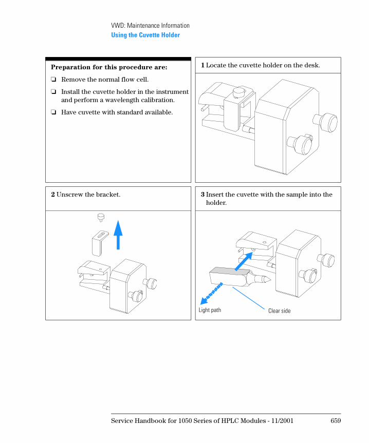
VWD: Maintenance InformationUsing the Cuvette Holder
Preparation for this procedure are:
❏ Remove the normal flow cell.
❏ Install the cuvette holder in the instrument and perform a wavelength calibration.
❏ Have cuvette with standard available.
1 Locate the cuvette holder on the desk.
2 Unscrew the bracket. 3 Insert the cuvette with the sample into the holder.
Light path Clear side
Service Handbook for 1050 Series of HPLC Modules - 11/2001 659
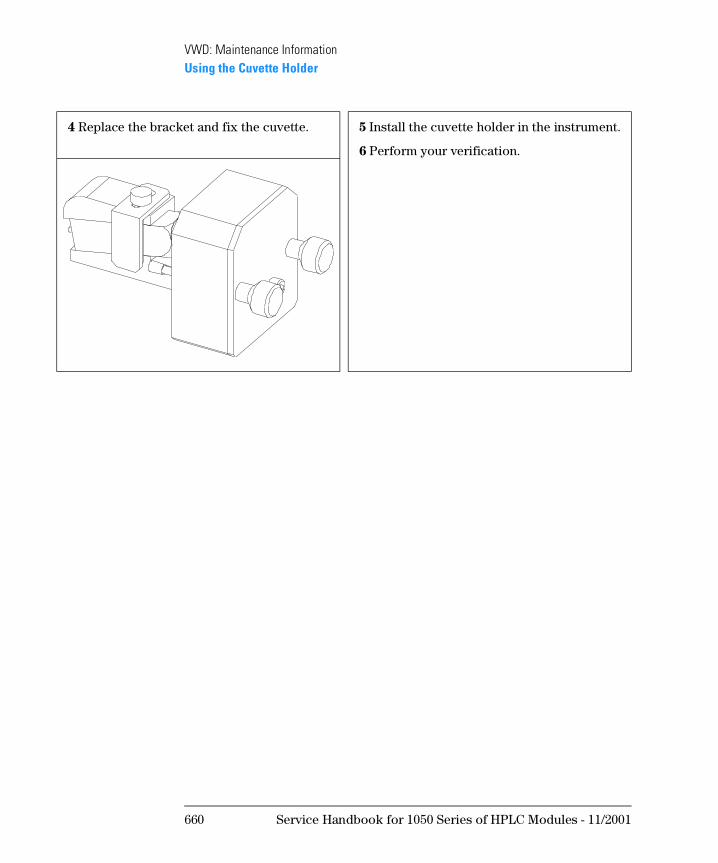
VWD: Maintenance InformationUsing the Cuvette Holder
4 Replace the bracket and fix the cuvette. 5 Install the cuvette holder in the instrument.
6 Perform your verification.
660 Service Handbook for 1050 Series of HPLC Modules - 11/2001
VWD: Maintenance InformationReplacing DCB Board and Firmware
Replacing DCB Board and Firmware
When performing one of these tasks, take care for electrostatic discharge protection to keep the electronics alive.
DCB Board
❏ Note the parameters from 31:SET WL PARAM.
❏ Disconnect the power from the instrument.
❏ Remove main cover and disconnect all connectors from DCB.
❏ Replace DCB after loosening the 3 fixing screws.
❏ Fix all screws and reconnect all connectors to the DCB.
❏ Carefully remove the firmware ROM from removed DCB and insert it on new DCB.
❏ Replace main cover and turn the instrument ON.
❏ Turn lamp on and wait some minutes to stabilize the lamp.
❏ Perform functions 20:0th CALIB., 21:WL CALIBRATION, 44:DAC CALIB. and 45:COMPENSATE to input the detector specific parameters into the EEROM.
DCB Firmware
❏ Disconnect the power from the instrument.
❏ Remove main cover.
❏ Carefully replace the firmware ROM.
❏ Replace main cover and turn the instrument ON.
❏ Turn lamp on and wait some minutes to stabilize the lamp.
Service Handbook for 1050 Series of HPLC Modules - 11/2001 661
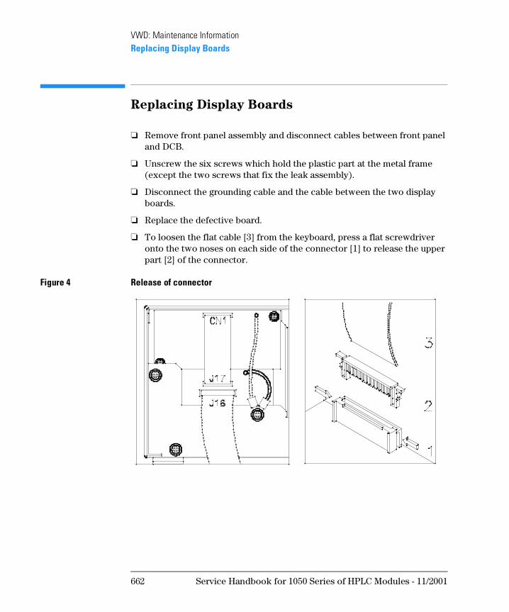
VWD: Maintenance InformationReplacing Display Boards
Replacing Display Boards
❏ Remove front panel assembly and disconnect cables between front panel and DCB.
❏ Unscrew the six screws which hold the plastic part at the metal frame (except the two screws that fix the leak assembly).
❏ Disconnect the grounding cable and the cable between the two display boards.
❏ Replace the defective board.
❏ To loosen the flat cable [3] from the keyboard, press a flat screwdriver onto the two noses on each side of the connector [1] to release the upper part [2] of the connector.
Figure 4 Release of connector
662 Service Handbook for 1050 Series of HPLC Modules - 11/2001
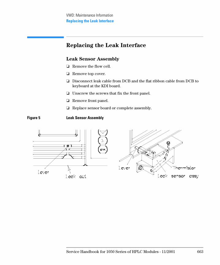
VWD: Maintenance InformationReplacing the Leak Interface
Replacing the Leak Interface
Leak Sensor Assembly
❏ Remove the flow cell.
❏ Remove top cover.
❏ Disconnect leak cable from DCB and the flat ribbon cable from DCB to keyboard at the KDI board.
❏ Unscrew the screws that fix the front panel.
❏ Remove front panel.
❏ Replace sensor board or complete assembly.
Figure 5 Leak Sensor Assembly
Service Handbook for 1050 Series of HPLC Modules - 11/2001 663
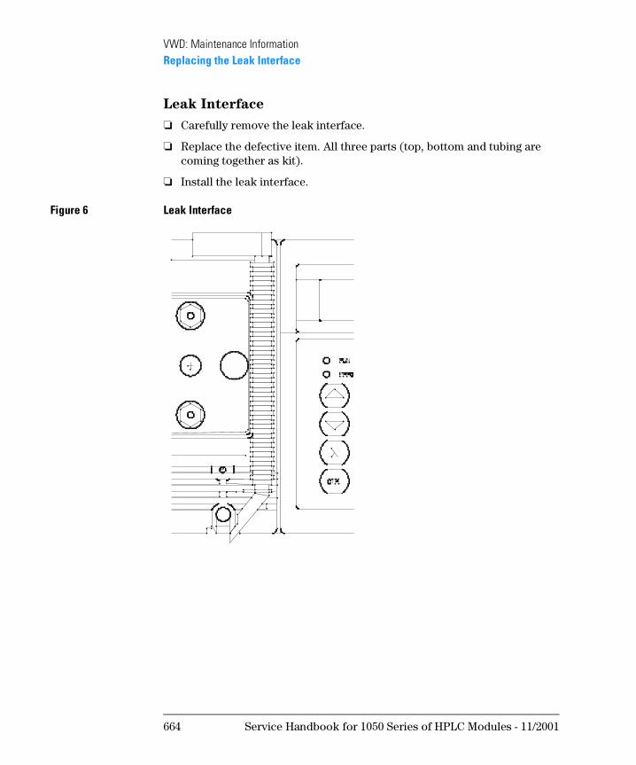
VWD: Maintenance InformationReplacing the Leak Interface
Leak Interface
❏ Carefully remove the leak interface.
❏ Replace the defective item. All three parts (top, bottom and tubing are coming together as kit).
❏ Install the leak interface.
Figure 6 Leak Interface
664 Service Handbook for 1050 Series of HPLC Modules - 11/2001
VWD: Maintenance InformationReplacements in the Optical Unit
Replacements in the Optical Unit
The repair level of optical unit parts is component level.
Refer to section “Optical Unit “C”” on page 688 for additional parts.
N OT E The information in this chapter is based on the original optical unit (version “C”). In June 1995 this optical was replaced by the enhanced version “D” to overcome baseline stability problems in unstable environments.
For details on this “D” version refer to section Enhanced Optical Unit Information “VWD: Enhanced Optical Unit Information” on page 705.
WA RN I N G Be sure to wear a pair of safety or sun glasses. Since the deuterium
lamp emits intensive ultraviolet light, it is dangerous to perform
optical alignment without eye protection. Be careful not to expose
your eyes directly to the light coming from the lamp.
Service Handbook for 1050 Series of HPLC Modules - 11/2001 665
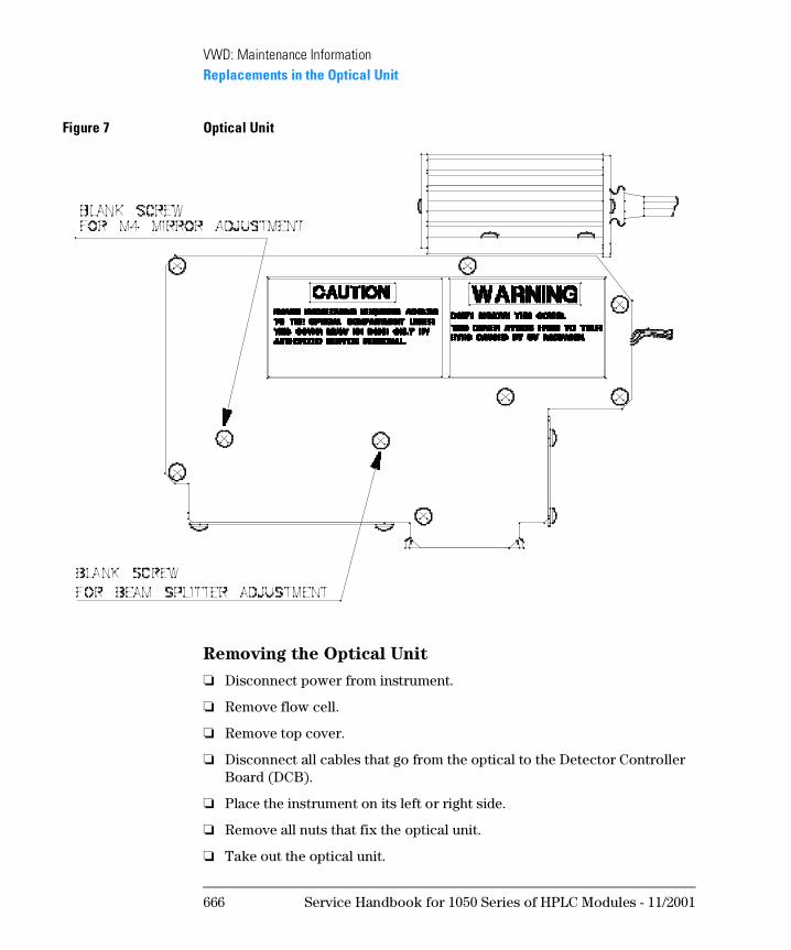
VWD: Maintenance InformationReplacements in the Optical Unit
Figure 7 Optical Unit
Removing the Optical Unit
❏ Disconnect power from instrument.
❏ Remove flow cell.
❏ Remove top cover.
❏ Disconnect all cables that go from the optical to the Detector Controller Board (DCB).
❏ Place the instrument on its left or right side.
❏ Remove all nuts that fix the optical unit.
❏ Take out the optical unit.
666 Service Handbook for 1050 Series of HPLC Modules - 11/2001
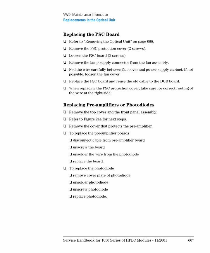
VWD: Maintenance InformationReplacements in the Optical Unit
Replacing the PSC Board
❏ Refer to “Removing the Optical Unit” on page 666.
❏ Remove the PSC protection cover (2 screws).
❏ Loosen the PSC board (3 screws).
❏ Remove the lamp supply connector from the fan assembly.
❏ Fed the wire carefully between fan cover and power supply cabinet. If not possible, loosen the fan cover.
❏ Replace the PSC board and reuse the old cable to the DCB board.
❏ When replacing the PSC protection cover, take care for correct routing of the wire at the right side.
Replacing Pre-amplifiers or Photodiodes
❏ Remove the top cover and the front panel assembly.
❏ Refer to Figure 244 for next steps.
❏ Remove the cover that protects the pre-amplifier.
❏ To replace the pre-amplifier boards
❏ disconnect cable from pre-amplifier board
❏ unscrew the board
❏ unsolder the wire from the photodiode
❏ replace the board.
❏ To replace the photodiode
❏ remove cover plate of photodiode
❏ unsolder photodiode
❏ unscrew photodiode
❏ replace photodiode.
Service Handbook for 1050 Series of HPLC Modules - 11/2001 667
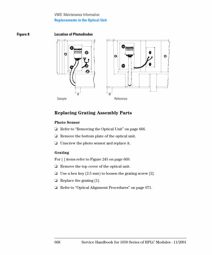
VWD: Maintenance InformationReplacements in the Optical Unit
Figure 8 Location of Photodiodes
Replacing Grating Assembly Parts
Photo Sensor
❏ Refer to “Removing the Optical Unit” on page 666.
❏ Remove the bottom plate of the optical unit.
❏ Unscrew the photo sensor and replace it.
Grating
For [ ] items refer to Figure 245 on page 669.
❏ Remove the top cover of the optical unit.
❏ Use a hex key (2.5 mm) to loosen the grating screw [2].
❏ Replace the grating [1].
❏ Refer to “Optical Alignment Procedures” on page 671.
Sample Reference
668 Service Handbook for 1050 Series of HPLC Modules - 11/2001
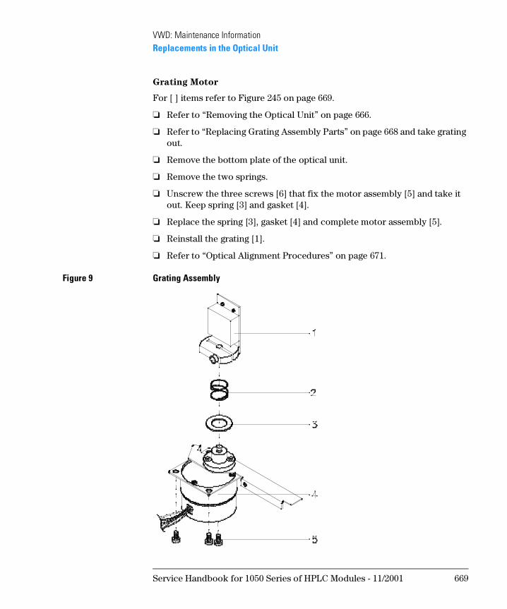
VWD: Maintenance InformationReplacements in the Optical Unit
Grating Motor
For [ ] items refer to Figure 245 on page 669.
❏ Refer to “Removing the Optical Unit” on page 666.
❏ Refer to “Replacing Grating Assembly Parts” on page 668 and take grating out.
❏ Remove the bottom plate of the optical unit.
❏ Remove the two springs.
❏ Unscrew the three screws [6] that fix the motor assembly [5] and take it out. Keep spring [3] and gasket [4].
❏ Replace the spring [3], gasket [4] and complete motor assembly [5].
❏ Reinstall the grating [1].
❏ Refer to “Optical Alignment Procedures” on page 671.
Figure 9 Grating Assembly
Service Handbook for 1050 Series of HPLC Modules - 11/2001 669
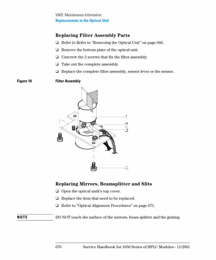
VWD: Maintenance InformationReplacements in the Optical Unit
Replacing Filter Assembly Parts
❏ Refer to Refer to “Removing the Optical Unit” on page 666.
❏ Remove the bottom plate of the optical unit.
❏ Unscrew the 2 screws that fix the filter assembly.
❏ Take out the complete assembly.
❏ Replace the complete filter assembly, sensor lever or the sensor.
Figure 10 Filter Assembly
Replacing Mirrors, Beamsplitter and Slits
❏ Open the optical untit's top cover.
❏ Replace the item that need to be replaced.
❏ Refer to “Optical Alignment Procedures” on page 671.
N OT E DO NOT touch the surface of the mirrors, beam splitter and the grating.
670 Service Handbook for 1050 Series of HPLC Modules - 11/2001
VWD: Maintenance InformationOptical Alignment Procedures
Optical Alignment Procedures
WA RN I N G Be sure to wear a pair of safety or sun glasses. Since the deuterium
lamp emits intensive ultraviolet light, it is dangerous to perform
optical alignment without eye protection. Be careful not to expose
your eyes directly to the light coming from the lamp.
Procedure 1: Simple Alignment
When replacing just a single part in the light path other than grating parts, M4 and beam splitter, this procedure can be performed.
❏ Execute 40:0th TEST which shows the step number from 31: SET WL PARM. and watch the location of the images on the slit assemblies (entrance and reference slit) and the cell center.
❏ Exchange the part Refer to Replacing ... for more information.
❏ Position the part so that the image centers on entrance and reference slit.
❏ Fix the part.
❏ If image on exit slit is too high or low, follow procedure “Procedure 2: Sample Beam Alignment” on page 672.
❏ If image on reference slit is too high or low, follow procedure “Procedure 3: Reference Beam Alignment” on page 674.
❏ Excute the 20:0th CALIB. and 21:WL CALIBRATION.
❏ Refer to “Replacement of Deuterium Lamp” on page 652, Step 2 and 3.
Procedure 1: alignment after exchange of a specific part
Procedure 2: alignment of complete optical (sample path)
Procedure 3: alignment of complete optical (reference path)
Service Handbook for 1050 Series of HPLC Modules - 11/2001 671
VWD: Maintenance InformationOptical Alignment Procedures
Procedure 2: Sample Beam Alignment
For [ ] items refer to Figure 247.
M1, M2, Entrance Slit, M3
❏ Remove the entrance slit [3].
❏ Turn the deuterium lamp [1] on.
❏ Make sure the light spot covers over mirror M1 [4].
❏ Adjust the direction of mirror M1 [4] so that the light beam covers over mirror M2 [5].
❏ Adjust the angle and direction of mirror M2 [5] so that the light beam covers over mirror M3 [6].
❏ Install the entrance slit [3] where the light beam illuminates the center of the slit.
❏ Adjust the angle and direction of the mirror M3 [6] so that the light beam covers over the grating mirror [7].
Figure 11 Optical Unit Parts
672 Service Handbook for 1050 Series of HPLC Modules - 11/2001
VWD: Maintenance InformationOptical Alignment Procedures
Grating, M4, Beam Splitter
❏ Excute control function 40:0TH TEST OFF to set the grating motor position to 200 steps (center step number).
❏ Adjust the direction of the grating mirror [7] so that the light beam covers over the mirror M4 [6].
❏ Remove the beam splitter [8] now so that you can see the center of the flow cell.
❏ Adjust the angle and direction of the mirror M4 [6] so that the light beam illuminates the center of the flow cell.
❏ Leave control function 40:0TH TEST OFF and return to normal display.
❏ Excute the 20:0th CALIB. and 21:WL CALIBRATION. Refer to “Replacement of Deuterium Lamp” on page 652, Step 2 and 3.
❏ If grating has been moved, use 45:COMPENSATE to compensate non-linearity of the grating motor.
❏ Set wavelength to 254nm.
❏ Place cover on optical unit (do not fix the screws at this time).
M4 fine tuning ❏ Excute control function 16:PHOTOCURRENT.
❏ Remove the blank screw for mirror M4 adjustment (Figure 243 on page 666) on the top cover (leave the blank screw for beam splitter adjustment in).
❏ Adjust the angle of the mirror M4 with inserting a hexagon wrench (1.5 mm) through the top cover screw hole to get maximum photocurrent for the sample. Turn right to move image down and left for up.
❏ Replace the blank screw in the top cover.
❏ Excute the 20:0th CALIB. and 21:WL CALIBRATION. Refer to “Replacement of Deuterium Lamp” on page 652, Step 2 and 3.
❏ Install the beam splitter [8].
Service Handbook for 1050 Series of HPLC Modules - 11/2001 673
VWD: Maintenance InformationOptical Alignment Procedures
Procedure 3: Reference Beam Alignment
For [ ] items refer to Figure 247 on page 672.
❏ Excute 40:0TH TEST ON with calibrated step value displayed.
❏ Open the top cover and adjust the angle and direction of the beam splitter [8], so that the light beam illuminates the center of the reference slit [12].
❏ Place the cover on the optical unit.
❏ Leave 40:0TH TEST ON and set wavelength to 254 nm.-
❏ Remove the blank screw for beam splitter adjustment (Figure 243 on page 666) in the top cover.
❏ Excute 16:PHOTOCURRENT.
❏ Adjust the angle of the beam splitter inserting a hexagon wrench through the top cover screw hole to get maximum photocurrent for the reference. Turn right to move image down and left for up.
❏ Replace the blank screw in the top cover.
❏ Repeat the 20:0TH CALIB. and 21:WL CALIBRATION. Refer to “Replacement of Deuterium Lamp” on page 652, Step 2 and 3.
❏ Use 45:COMPENSATE to compensate non-linearity of the grating motor.
674 Service Handbook for 1050 Series of HPLC Modules - 11/2001
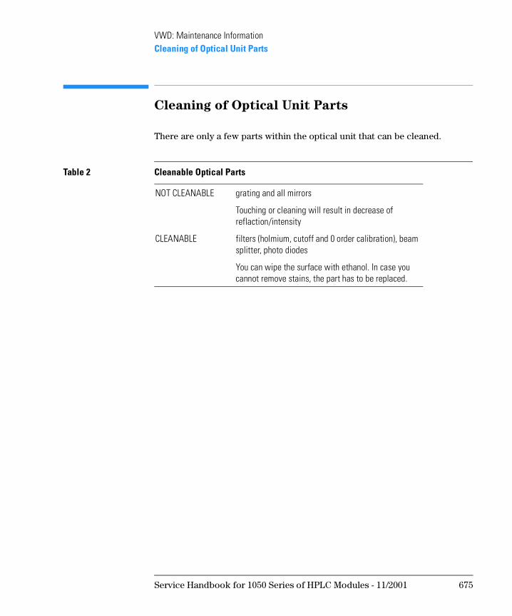
VWD: Maintenance InformationCleaning of Optical Unit Parts
Cleaning of Optical Unit Parts
There are only a few parts within the optical unit that can be cleaned.
Table 2 Cleanable Optical Parts
NOT CLEANABLE grating and all mirrors
Touching or cleaning will result in decrease of reflaction/intensity
CLEANABLE filters (holmium, cutoff and 0 order calibration), beam splitter, photo diodes
You can wipe the surface with ethanol. In case you cannot remove stains, the part has to be replaced.
Service Handbook for 1050 Series of HPLC Modules - 11/2001 675
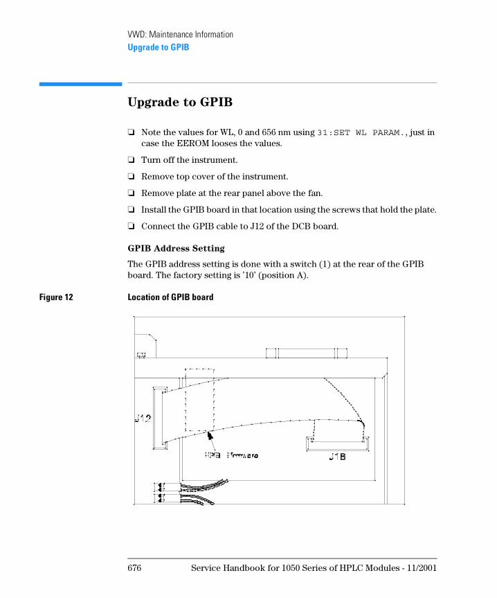
VWD: Maintenance InformationUpgrade to GPIB
Upgrade to GPIB
❏ Note the values for WL, 0 and 656 nm using 31:SET WL PARAM., just in case the EEROM looses the values.
❏ Turn off the instrument.
❏ Remove top cover of the instrument.
❏ Remove plate at the rear panel above the fan.
❏ Install the GPIB board in that location using the screws that hold the plate.
❏ Connect the GPIB cable to J12 of the DCB board.
GPIB Address Setting
The GPIB address setting is done with a switch (1) at the rear of the GPIB board. The factory setting is ’10’ (position A).
Figure 12 Location of GPIB board
676 Service Handbook for 1050 Series of HPLC Modules - 11/2001
VWD: Maintenance InformationPerformance Verification
Performance Verification
What you need
❏ a pump that can deliver bidistilled water, at a rate of up to 1 ml/min against a back-pressure of about 200 bar.
❏ a column: we recommend our 100 x 4.6 mm i.d., 5 µm Hypersil ODS column.
❏ a recording device that can accept the output signal from your detector and that has attenuation set to about 35 cm/mV.
Preparations
❏ Prime the pump and ensure there are no air bubbles in the system.
❏ Thoroughly degas about 300 ml of bidistilled water.
❏ Set pump to deliver bidstilled water at a flow rate of 1 ml/min.
❏ Set the attenuation to about 35 cm/mV.
❏ Set run time on recorder to 6.0 min.
❏ Turn-ON line power and deuterium lamp.
❏ Set wavelength to 254 nm, response time to 1 second and output voltage to 1 V.
Table 3 Noise and Drift Specifications
Noise 1.5 x 10⁻⁵ AU
Drift 5.0 x 10⁻⁴ AU/h
Service Handbook for 1050 Series of HPLC Modules - 11/2001 677
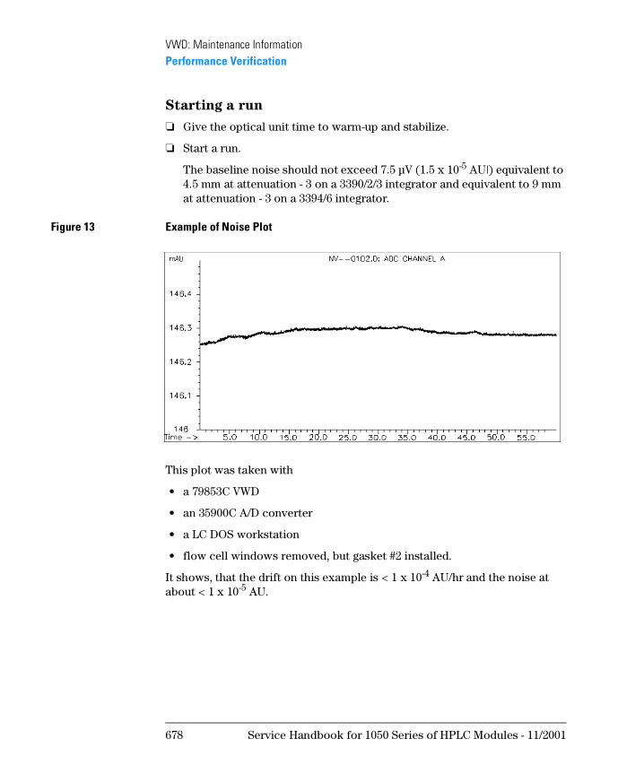
VWD: Maintenance InformationPerformance Verification
Starting a run
❏ Give the optical unit time to warm-up and stabilize.
❏ Start a run.
The baseline noise should not exceed 7.5 µV (1.5 x 10⁻⁵ AU|) equivalent to 4.5 mm at attenuation - 3 on a 3390/2/3 integrator and equivalent to 9 mm at attenuation - 3 on a 3394/6 integrator.
Figure 13 Example of Noise Plot
This plot was taken with
• a 79853C VWD
• an 35900C A/D converter
• a LC DOS workstation
• flow cell windows removed, but gasket #2 installed.
It shows, that the drift on this example is < 1 x 10⁻⁴ AU/hr and the noise at about < 1 x 10⁻⁵ AU.
678 Service Handbook for 1050 Series of HPLC Modules - 11/2001
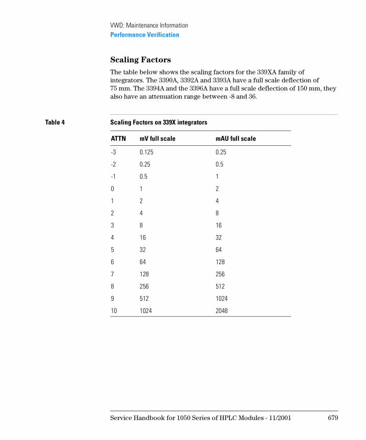
VWD: Maintenance InformationPerformance Verification
Scaling Factors
The table below shows the scaling factors for the 339XA family of integrators. The 3390A, 3392A and 3393A have a full scale deflection of 75 mm. The 3394A and the 3396A have a full scale deflection of 150 mm, they also have an attenuation range between -8 and 36.
Table 4 Scaling Factors on 339X integrators
ATTN mV full scale mAU full scale
-3 0.125 0.25
-2 0.25 0.5
-1 0.5 1
0 1 2
1 2 4
2 4 8
3 8 16
4 16 32
5 32 64
6 64 128
7 128 256
8 256 512
9 512 1024
10 1024 2048
Service Handbook for 1050 Series of HPLC Modules - 11/2001 679

VWD: Maintenance InformationPerformance Verification
680 Service Handbook for 1050 Series of HPLC Modules - 11/2001
1
1 VWD: Parts Information
This chapter provides information on parts of the 1050 Variable Wavelength Detectors
VWD: Parts Information
This chapter gives diagrams for parts identification and the complete parts listings respectively.
• Overall Diagram
• Optical Unit
• Flowcell
• Flow Cell Kits
• Accessory Kit
N OT E The information in this chapter is based on the original optical unit (version “C”). In June 1995 this optical was replaced by the enhanced version “D” to overcome baseline stability problems in unstable environments.
For details on this “D” version refer to section Enhanced Optical Unit Information “VWD: Enhanced Optical Unit Information” on page 705.
682 Service Handbook for 1050 Series of HPLC Modules - 11/2001
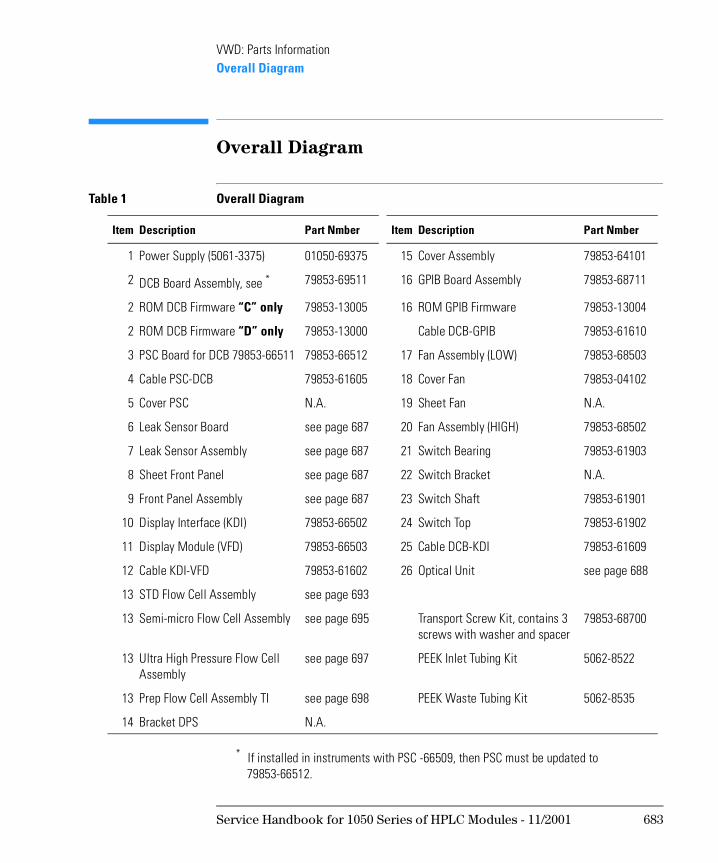
VWD: Parts InformationOverall Diagram
Overall Diagram
Table 1 Overall Diagram
Item Description Part Nmber Item Description Part Nmber
1 Power Supply (5061-3375) 01050-69375 15 Cover Assembly 79853-64101
2 DCB Board Assembly, see *
* If installed in instruments with PSC -66509, then PSC must be updated to 79853-66512.
79853-69511 16 GPIB Board Assembly 79853-68711
2 ROM DCB Firmware “C” only 79853-13005 16 ROM GPIB Firmware 79853-13004
2 ROM DCB Firmware “D” only 79853-13000 Cable DCB-GPIB 79853-61610
3 PSC Board for DCB 79853-66511 79853-66512 17 Fan Assembly (LOW) 79853-68503
4 Cable PSC-DCB 79853-61605 18 Cover Fan 79853-04102
5 Cover PSC N.A. 19 Sheet Fan N.A.
6 Leak Sensor Board see page 687 20 Fan Assembly (HIGH) 79853-68502
7 Leak Sensor Assembly see page 687 21 Switch Bearing 79853-61903
8 Sheet Front Panel see page 687 22 Switch Bracket N.A.
9 Front Panel Assembly see page 687 23 Switch Shaft 79853-61901
10 Display Interface (KDI) 79853-66502 24 Switch Top 79853-61902
11 Display Module (VFD) 79853-66503 25 Cable DCB-KDI 79853-61609
12 Cable KDI-VFD 79853-61602 26 Optical Unit see page 688
13 STD Flow Cell Assembly see page 693
13 Semi-micro Flow Cell Assembly see page 695 Transport Screw Kit, contains 3 screws with washer and spacer
79853-68700
13 Ultra High Pressure Flow Cell Assembly
see page 697 PEEK Inlet Tubing Kit 5062-8522
13 Prep Flow Cell Assembly TI see page 698 PEEK Waste Tubing Kit 5062-8535
14 Bracket DPS N.A.
Service Handbook for 1050 Series of HPLC Modules - 11/2001 683
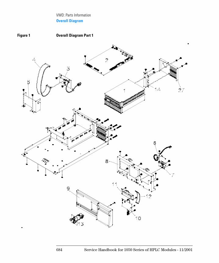
VWD: Parts InformationOverall Diagram
Figure 1 Overall Diagram Part 1
684 Service Handbook for 1050 Series of HPLC Modules - 11/2001
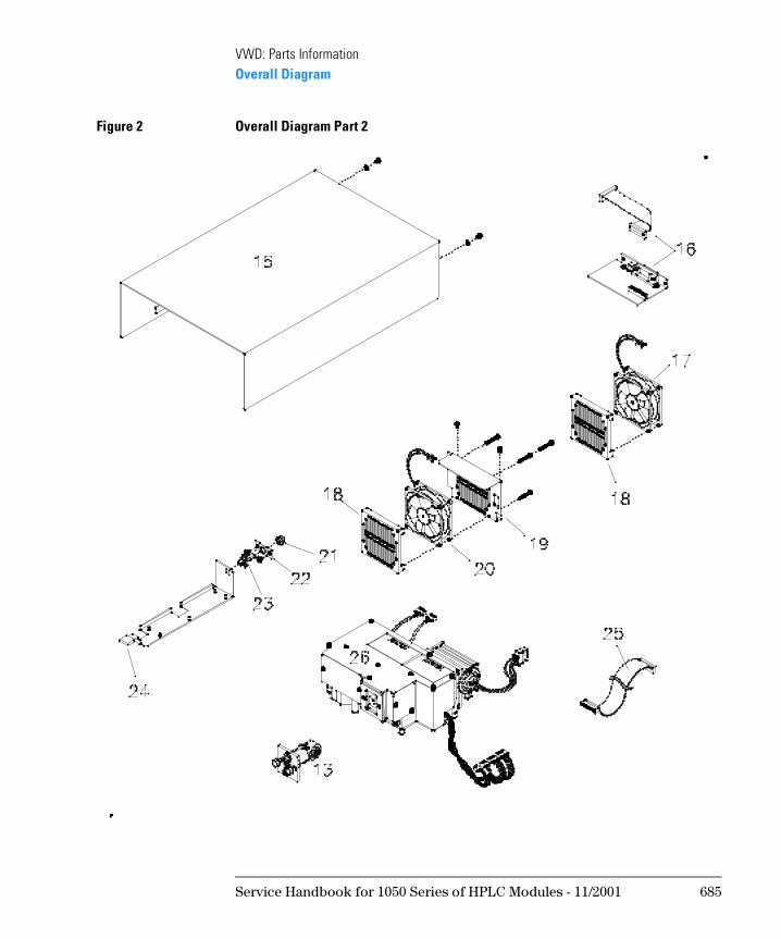
VWD: Parts InformationOverall Diagram
Figure 2 Overall Diagram Part 2
Service Handbook for 1050 Series of HPLC Modules - 11/2001 685
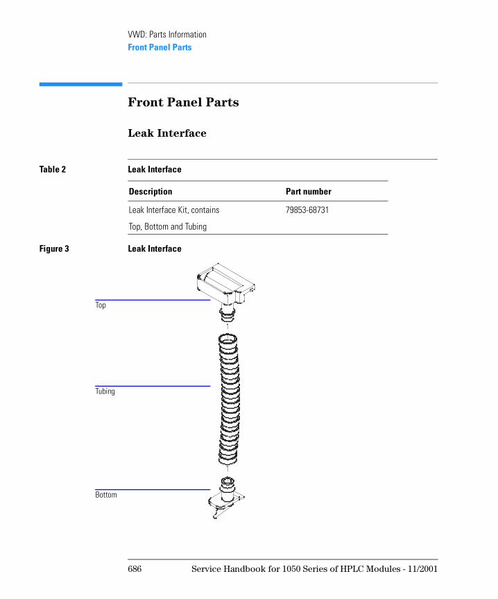
VWD: Parts InformationFront Panel Parts
Front Panel Parts
Leak Interface
Figure 3 Leak Interface
Table 2 Leak Interface
Description Part number
Leak Interface Kit, contains 79853-68731
Top, Bottom and Tubing
Top
Tubing
Bottom
686 Service Handbook for 1050 Series of HPLC Modules - 11/2001
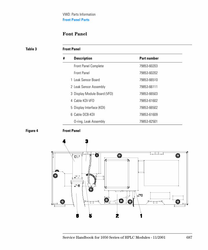
VWD: Parts InformationFront Panel Parts
Font Panel
Figure 4 Front Panel
Table 3 Front Panel
# Description Part number
Front Panel Complete 79853-60203
Front Panel 79853-60202
1 Leak Sensor Board 79853-66510
2 Leak Sensor Assembly 79853-66111
3 Display Module Board (VFD) 79853-66503
4 Cable KDI-VFD 79853-61602
5 Display Interface (KDI) 79853-66502
6 Cable DCB-KDI 79853-61609
O-ring, Leak Assembly 79853-82501
Service Handbook for 1050 Series of HPLC Modules - 11/2001 687
VWD: Parts InformationOptical Unit “C”
Optical Unit “C”
The parts identification of the optical unit is splitted into four sections:
• Optical Unit Inner Parts (Top)
• Optical Unit Inner Parts (Bottom)
• Grating Assembly
• Filter Assembly
• Flow Cell Assemblies
N OT E The information in this chapter is based on the original optical unit (version “C”). In June 1995 this optical was replaced by the enhanced version “D” to overcome baseline stability problems in unstable environments.
For details on this “D” version refer to section Enhanced Optical Unit Information “VWD: Enhanced Optical Unit Information” on page 705.
For complete optical unit “C” replacements use part number 79853-60015. This upgrades to “D” version, see “Part Numbers for Enhanced “D” Optical
Unit” on page 709
688 Service Handbook for 1050 Series of HPLC Modules - 11/2001
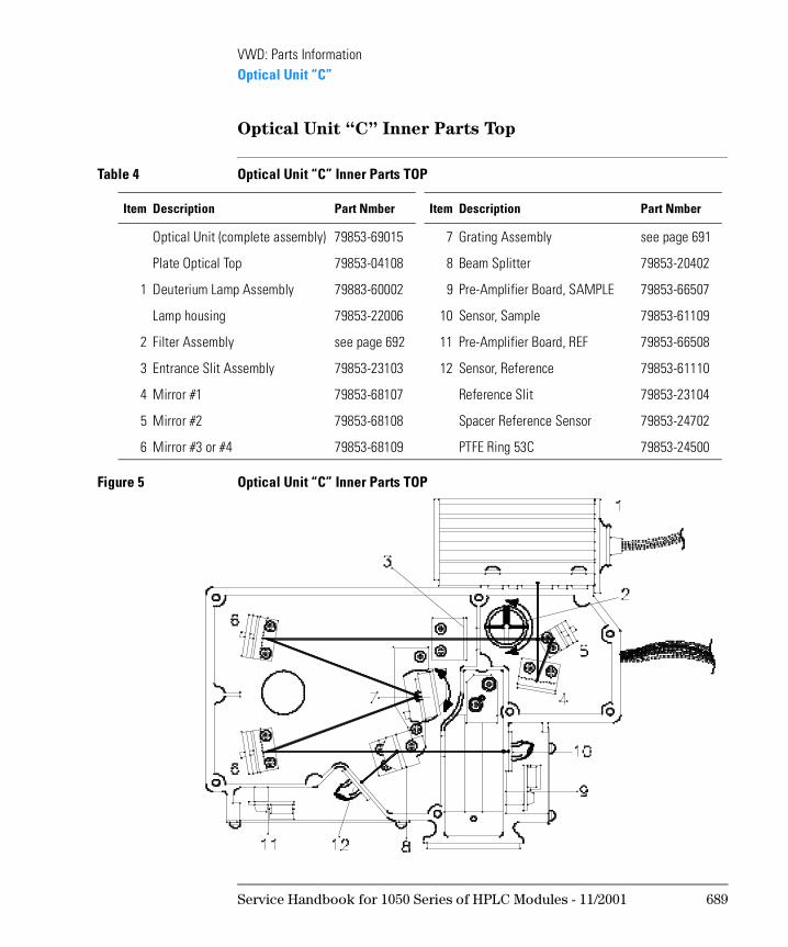
VWD: Parts InformationOptical Unit “C”
Optical Unit “C” Inner Parts Top
Figure 5 Optical Unit “C” Inner Parts TOP
Table 4 Optical Unit “C” Inner Parts TOP
Item Description Part Nmber Item Description Part Nmber
Optical Unit (complete assembly) 79853-69015 7 Grating Assembly see page 691
Plate Optical Top 79853-04108 8 Beam Splitter 79853-20402
1 Deuterium Lamp Assembly 79883-60002 9 Pre-Amplifier Board, SAMPLE 79853-66507
Lamp housing 79853-22006 10 Sensor, Sample 79853-61109
2 Filter Assembly see page 692 11 Pre-Amplifier Board, REF 79853-66508
3 Entrance Slit Assembly 79853-23103 12 Sensor, Reference 79853-61110
4 Mirror #1 79853-68107 Reference Slit 79853-23104
5 Mirror #2 79853-68108 Spacer Reference Sensor 79853-24702
6 Mirror #3 or #4 79853-68109 PTFE Ring 53C 79853-24500
Service Handbook for 1050 Series of HPLC Modules - 11/2001 689
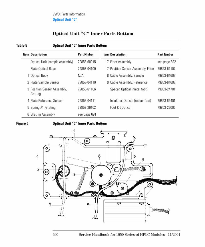
VWD: Parts InformationOptical Unit “C”
Optical Unit “C” Inner Parts Bottom
Figure 6 Optical Unit “C” Inner Parts Bottom
Table 5 Optical Unit “C” Inner Parts Bottom
Item Description Part Nmber Item Description Part Nmber
Optical Unit (comple assembly) 79853-60015 7 Filter Assembly see page 692
Plate Optical Base 79853-04109 7 Position Sensor Assembly, Filter 79853-61107
1 Optical Body N/A 8 Cable Assembly, Sample 79853-61607
2 Plate Sample Sensor 79853-04110 9 Cable Assembly, Reference 79853-61608
3 Position Sensor Assembly, Grating
79853-61106 Spacer, Optical (metal foot) 79853-24701
4 Plate Reference Sensor 79853-04111 Insulator, Optical (rubber foot) 79853-85401
5 Spring #1, Grating 79853-29102 Foot Kit Optical 79853-22005
6 Grating Assembly see page 691
690 Service Handbook for 1050 Series of HPLC Modules - 11/2001
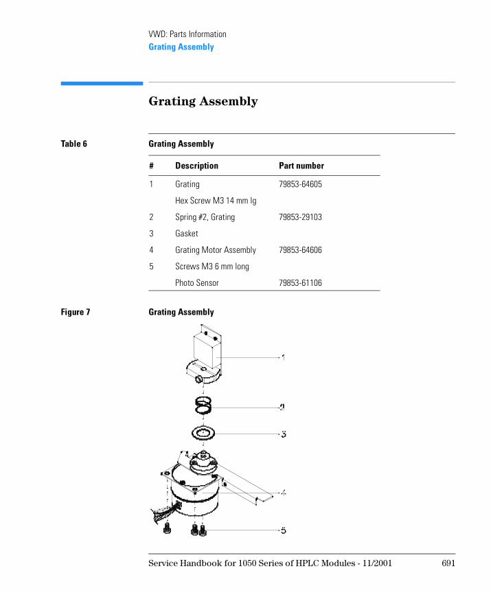
VWD: Parts InformationGrating Assembly
Grating Assembly
Figure 7 Grating Assembly
Table 6 Grating Assembly
# Description Part number
1 Grating 79853-64605
Hex Screw M3 14 mm lg
2 Spring #2, Grating 79853-29103
3 Gasket
4 Grating Motor Assembly 79853-64606
5 Screws M3 6 mm long
Photo Sensor 79853-61106
Service Handbook for 1050 Series of HPLC Modules - 11/2001 691
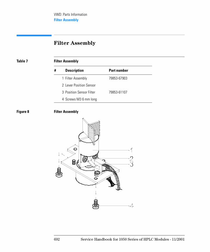
VWD: Parts InformationFilter Assembly
Filter Assembly
Figure 8 Filter Assembly
Table 7 Filter Assembly
# Description Part number
1 Filter Assembly 79853-67903
2 Lever Position Sensor
3 Position Sensor Filter 79853-61107
4 Screws M3 6 mm long
692 Service Handbook for 1050 Series of HPLC Modules - 11/2001
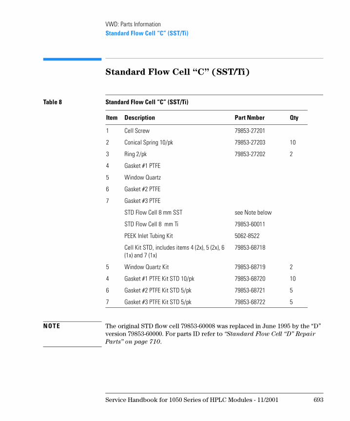
VWD: Parts InformationStandard Flow Cell “C” (SST/Ti)
Standard Flow Cell “C” (SST/Ti)
N OT E The original STD flow cell 79853-60008 was replaced in June 1995 by the “D” version 79853-60000. For parts ID refer to “Standard Flow Cell “D” Repair
Parts” on page 710.
Table 8 Standard Flow Cell “C” (SST/Ti)
Item Description Part Nmber Qty
1 Cell Screw 79853-27201
2 Conical Spring 10/pk 79853-27203 10
3 Ring 2/pk 79853-27202 2
4 Gasket #1 PTFE
5 Window Quartz
6 Gasket #2 PTFE
7 Gasket #3 PTFE
STD Flow Cell 8 mm SST see Note below
STD Flow Cell 8 mm Ti 79853-60011
PEEK Inlet Tubing Kit 5062-8522
Cell Kit STD, includes items 4 (2x), 5 (2x), 6 (1x) and 7 (1x)
79853-68718
5 Window Quartz Kit 79853-68719 2
4 Gasket #1 PTFE Kit STD 10/pk 79853-68720 10
6 Gasket #2 PTFE Kit STD 5/pk 79853-68721 5
7 Gasket #3 PTFE Kit STD 5/pk 79853-68722 5
Service Handbook for 1050 Series of HPLC Modules - 11/2001 693
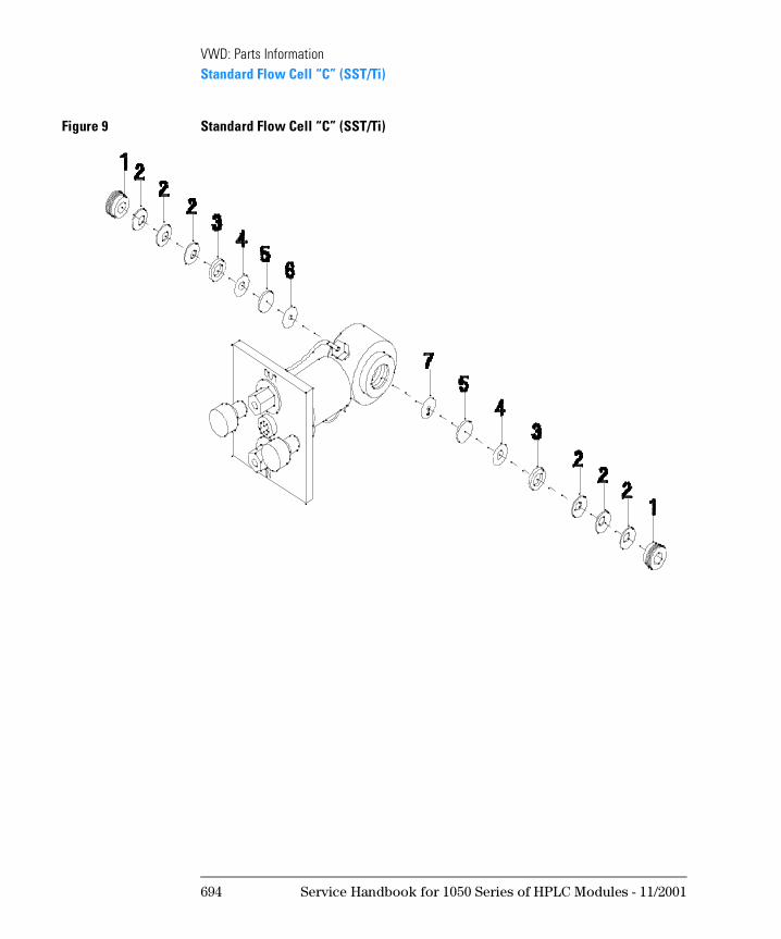
VWD: Parts InformationStandard Flow Cell “C” (SST/Ti)
Figure 9 Standard Flow Cell “C” (SST/Ti)
694 Service Handbook for 1050 Series of HPLC Modules - 11/2001
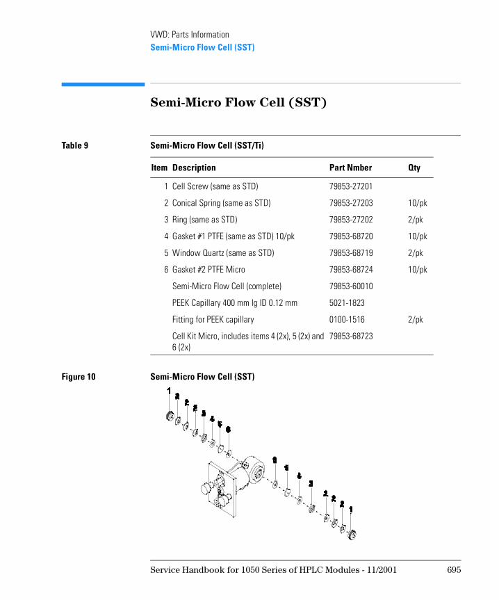
VWD: Parts InformationSemi-Micro Flow Cell (SST)
Semi-Micro Flow Cell (SST)
Figure 10 Semi-Micro Flow Cell (SST)
Table 9 Semi-Micro Flow Cell (SST/Ti)
Item Description Part Nmber Qty
1 Cell Screw (same as STD) 79853-27201
2 Conical Spring (same as STD) 79853-27203 10/pk
3 Ring (same as STD) 79853-27202 2/pk
4 Gasket #1 PTFE (same as STD) 10/pk 79853-68720 10/pk
5 Window Quartz (same as STD) 79853-68719 2/pk
6 Gasket #2 PTFE Micro 79853-68724 10/pk
Semi-Micro Flow Cell (complete) 79853-60010
PEEK Capillary 400 mm lg ID 0.12 mm 5021-1823
Fitting for PEEK capillary 0100-1516 2/pk
Cell Kit Micro, includes items 4 (2x), 5 (2x) and 6 (2x)
79853-68723
Service Handbook for 1050 Series of HPLC Modules - 11/2001 695
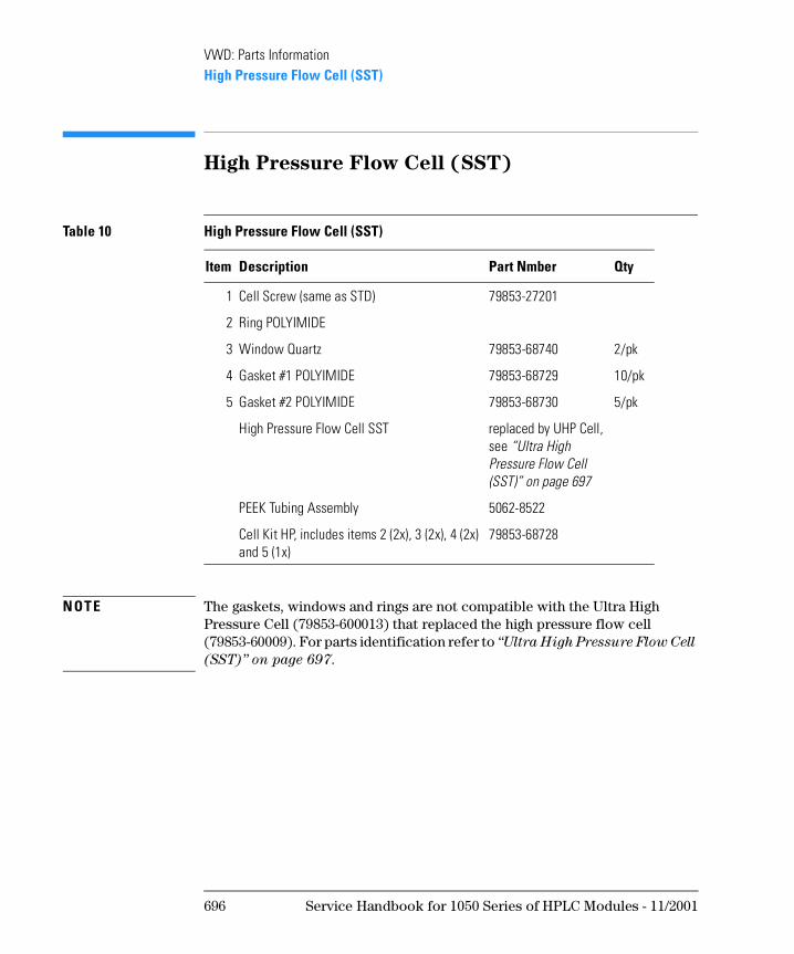
VWD: Parts InformationHigh Pressure Flow Cell (SST)
High Pressure Flow Cell (SST)
N OT E The gaskets, windows and rings are not compatible with the Ultra High Pressure Cell (79853-600013) that replaced the high pressure flow cell (79853-60009). For parts identification refer to “Ultra High Pressure Flow Cell
(SST)” on page 697.
Table 10 High Pressure Flow Cell (SST)
Item Description Part Nmber Qty
1 Cell Screw (same as STD) 79853-27201
2 Ring POLYIMIDE
3 Window Quartz 79853-68740 2/pk
4 Gasket #1 POLYIMIDE 79853-68729 10/pk
5 Gasket #2 POLYIMIDE 79853-68730 5/pk
High Pressure Flow Cell SST replaced by UHP Cell, see “Ultra High Pressure Flow Cell (SST)” on page 697
PEEK Tubing Assembly 5062-8522
Cell Kit HP, includes items 2 (2x), 3 (2x), 4 (2x) and 5 (1x)
79853-68728
696 Service Handbook for 1050 Series of HPLC Modules - 11/2001
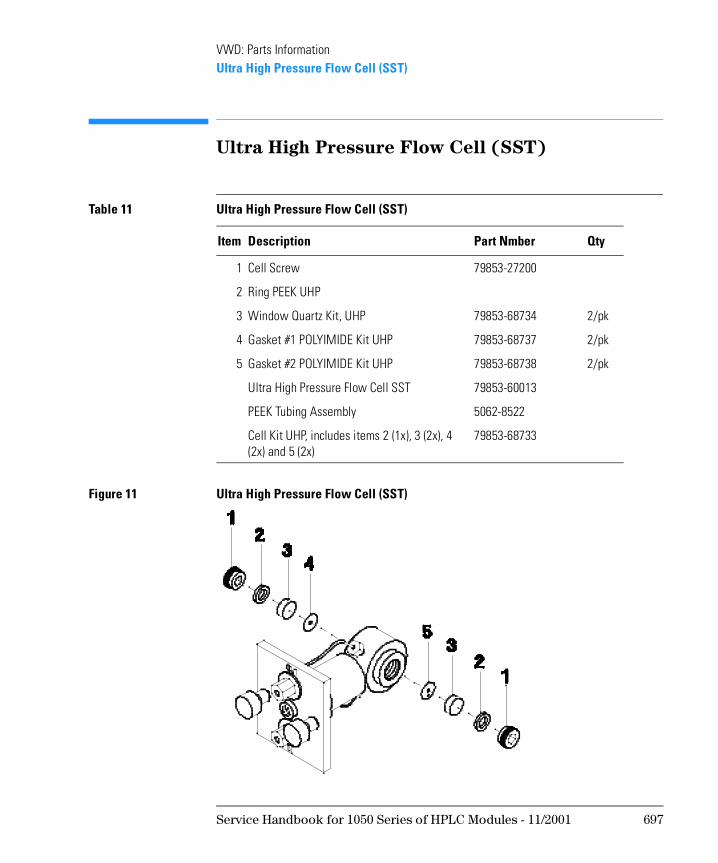
VWD: Parts InformationUltra High Pressure Flow Cell (SST)
Ultra High Pressure Flow Cell (SST)
Figure 11 Ultra High Pressure Flow Cell (SST)
Table 11 Ultra High Pressure Flow Cell (SST)
Item Description Part Nmber Qty
1 Cell Screw 79853-27200
2 Ring PEEK UHP
3 Window Quartz Kit, UHP 79853-68734 2/pk
4 Gasket #1 POLYIMIDE Kit UHP 79853-68737 2/pk
5 Gasket #2 POLYIMIDE Kit UHP 79853-68738 2/pk
Ultra High Pressure Flow Cell SST 79853-60013
PEEK Tubing Assembly 5062-8522
Cell Kit UHP, includes items 2 (1x), 3 (2x), 4 (2x) and 5 (2x)
79853-68733
Service Handbook for 1050 Series of HPLC Modules - 11/2001 697
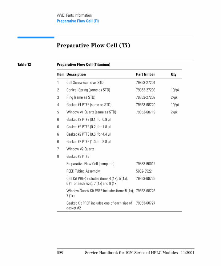
VWD: Parts InformationPreparative Flow Cell (Ti)
Preparative Flow Cell (Ti)
Table 12 Preparative Flow Cell (Titanium)
Item Description Part Nmber Qty
1 Cell Screw (same as STD) 79853-27201
2 Conical Spring (same as STD) 79853-27203 10/pk
3 Ring (same as STD) 79853-27202 2/pk
4 Gasket #1 PTFE (same as STD) 79853-68720 10/pk
5 Window #1 Quartz (same as STD) 79853-68719 2/pk
6 Gasket #2 PTFE (0.1) for 0.9 µl
6 Gasket #2 PTFE (0.2) for 1.8 µl
6 Gasket #2 PTFE (0.5) for 4.4 µl
6 Gasket #2 PTFE (1.0) for 8.8 µl
7 Window #2 Quartz
8 Gasket #3 PTFE
Preparative Flow Cell (complete) 79853-60012
PEEK Tubing Assembly 5062-8522
Cell Kit PREP, includes items 4 (1x), 5 (1x), 6 (1 of each size), 7 (1x) and 8 (1x)
79853-68725
Window Quartz Kit PREP includes items 5 (1x), 7 (1x)
79853-68726
Gasket Kit PREP includes one of each size of gasket #2
79853-68727
698 Service Handbook for 1050 Series of HPLC Modules - 11/2001
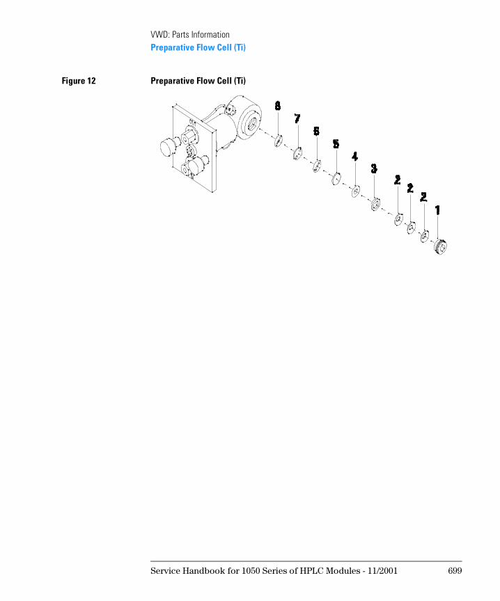
VWD: Parts InformationPreparative Flow Cell (Ti)
Figure 12 Preparative Flow Cell (Ti)
Service Handbook for 1050 Series of HPLC Modules - 11/2001 699
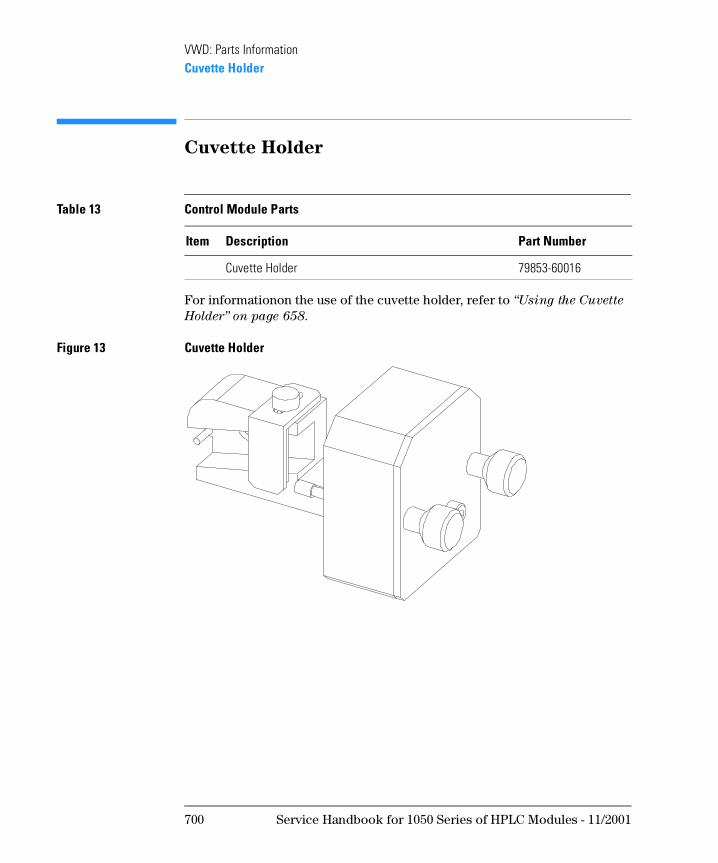
VWD: Parts InformationCuvette Holder
Cuvette Holder
For informationon the use of the cuvette holder, refer to “Using the Cuvette
Holder” on page 658.
Figure 13 Cuvette Holder
Table 13 Control Module Parts
Item Description Part Number
Cuvette Holder 79853-60016
700 Service Handbook for 1050 Series of HPLC Modules - 11/2001
VWD: Parts InformationAccessories
Accessories
These parts are shipped with the 79853C VWD
Table 14 Accessories
Description Part number QTY
Manual Getting Ready 01050-90211 1
Cable Remote 5061-3378 1
PEEK Waste Accessory Kit 5062-8535 1
Standard Accessory Kit 79853-68701 1
includes
Fitting 0100-1516 1
Fuse 250 V 2A 2110-0002 3
Fuse 250 V 3A 2110-0003 3
Wrench 1/4-5/16 inch 8710-0510 1
Screwdriver POZI 1 PT 3 8710-0899 1
Leak Interface Kit 79853-68731 1
Manual SOP 79853-90009 1
Service Handbook for 1050 Series of HPLC Modules - 11/2001 701
VWD: Parts InformationScrews
Screws
Below table lists all screws within the instrument. They can be bought locally, if needed.
Table 15 Screws
Location Size Length Type
filter motor M 2.3 4 mm lg hexagon socket set screw with cup point
grating motor M 3 3 mm lg hexagon socket set screw with cup point
mirror adjustment M 3 8 mm lg hexagon socket set screw with dog point
grating adjustment M 3 14 mm lg hexagon socket cap screw
grating motor M 3 4 mm lg countersink screw
to fix assemblies on the optical body; cover on the DCB board; plate of lamp house; KDI and VFD board; mirrors, filter and grating;
M 3 6 mm lg screw
position sensor M 3 6 mm lg screw with smaller head
REF sensor plate M 3 10 mm lg screw
SAMP and REF amplifier boards M 3 18 mm lg screw
cover assembly; optical unit top cover; DCB and GPIB boards from rear panel;
M 4 6 mm lg screw with lock washer
to fix assemblies on the base; DCB abd GPIB board; leak detector assembly; front panel bracket; SAMP and REF covers; optical unit bottom cover; blank screws of optical unit top cover; plate for cell on the optical body;
M 4 5 mm lg screw
blank plate of cell; lock screws M 4 12 mm lg screw
702 Service Handbook for 1050 Series of HPLC Modules - 11/2001
VWD: Parts InformationScrews
All screws are plus-shaped type.
lamp house M 4 14 mm lg screw
fan assemblies M 4 35 mm lg screw
cell M 5 10 mm lg screw
Table 15 Screws
Location Size Length Type
Service Handbook for 1050 Series of HPLC Modules - 11/2001 703
VWD: Parts InformationScrews
704 Service Handbook for 1050 Series of HPLC Modules - 11/2001
1
1 VWD: Enhanced Optical Unit
Information
This chapter provides information about the enhanced optical unit “D”
VWD: Enhanced Optical Unit
Information
Since June 1995, the design of the optical unit for the 79853C Variable Wavelength Detector (VWD) was changed to improve its performance under unstable temperature conditions.
Together with the enhanced optical unit (“D”), the standard flow cell was changed (79853-60000).
N OT E In this document the term “D” is used for the new enhanced optical design and “C” for the original optical design.
Compatibility
This new enhanced optical unit (“D”) is fully backward compatible with all79853C VWDs shipped since January 1992.
The new standard flow cell (79853-60000) is backward compatible with the “C” optical unit.
Some of the parts for the enhanced optical unit (“D”) are not usable in the “C” version.
In case of replacing a “C” optical unit with an enhanced “D” optical unit, the new standard flow cell is required.
Support of Previous Optical Units
The parts for the “C” optical unit will continue to be available as a repair part as long as the 79853C is supported (08/2006). In case the complete “C” optical must be replaced, use the “D” upgrade mentioned on “Part Numbers for
Enhanced “D” Optical Unit” on page 709.
706 Service Handbook for 1050 Series of HPLC Modules - 11/2001
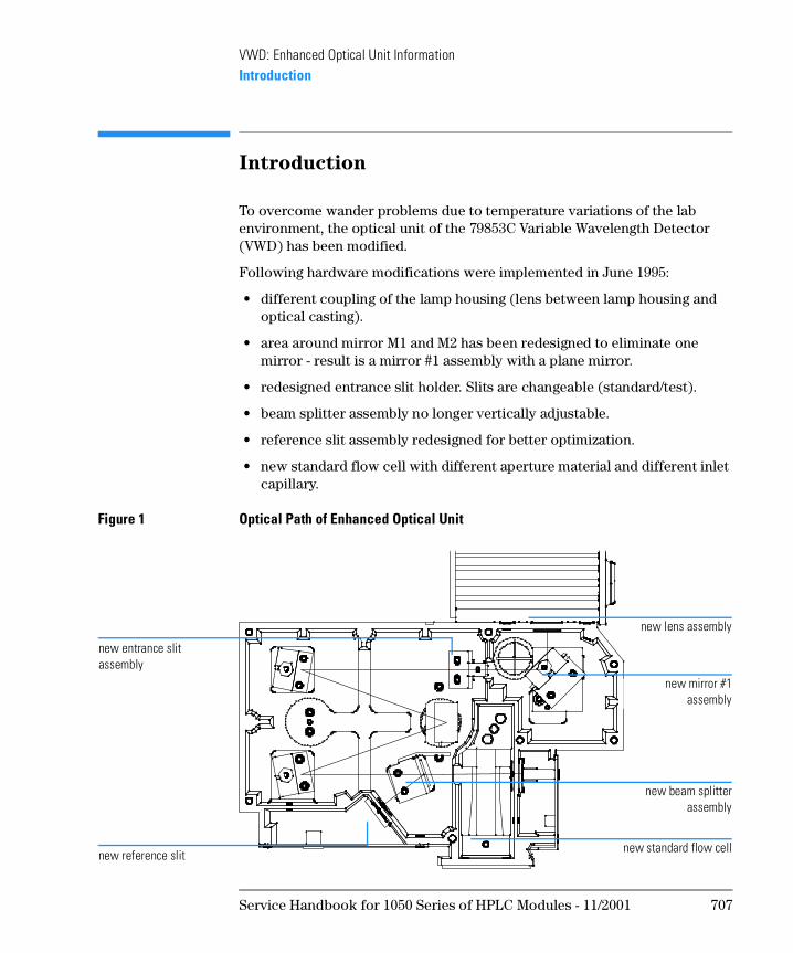
VWD: Enhanced Optical Unit InformationIntroduction
Introduction
To overcome wander problems due to temperature variations of the lab environment, the optical unit of the 79853C Variable Wavelength Detector (VWD) has been modified.
Following hardware modifications were implemented in June 1995:
• different coupling of the lamp housing (lens between lamp housing and optical casting).
• area around mirror M1 and M2 has been redesigned to eliminate one mirror - result is a mirror #1 assembly with a plane mirror.
• redesigned entrance slit holder. Slits are changeable (standard/test).
• beam splitter assembly no longer vertically adjustable.
• reference slit assembly redesigned for better optimization.
• new standard flow cell with different aperture material and different inlet capillary.
Figure 1 Optical Path of Enhanced Optical Unit
new mirror #1assembly
new lens assembly
new beam splitterassembly
new reference slit
new entrance slit assembly
new standard flow cell
Service Handbook for 1050 Series of HPLC Modules - 11/2001 707
VWD: Enhanced Optical Unit InformationSupport Considerations
Support Considerations
Prefix Change
The enhanced Optical Unit (“D” version) was introduced in production units in June 1995. Since the detector appears to look the same as before, a prefix change was made. All units with prefix 3522 J 04305 and above have the new optical installed.
N OT E Some units with a prefix lower than 3522 J 04305 have been installed on customer sites prior to the official shipments.
Identification
Following identifications for the enhanced “D” version are available:
• Prefix and serial number 3522 J 04305 and above (rear of instrument)
• firmware revision 4.31 (press CTRL 12 ENTER ENTER DOWN)
• label on the optical unit “ENHANCED ILLUMINATION SYSTEM”
• handle of new reference slit looking out of the optical’s cover plate (see Figure 266 on page 715).
Compatibility Matrix
Due to a redesign, several components are usable in the enhanced “D” version only. Refer to Table 191 on page 709 for details.
N OT E Both optical unit versions (“C” and “D”) can be operated with firmware revision 4.24 (79853-13005). Due to the modifications, the photocurrent readings are about 50% of those of the original “C” opticals. To make them comparable the firmware for the enhanced “D” version got a new revision and part number.
708 Service Handbook for 1050 Series of HPLC Modules - 11/2001
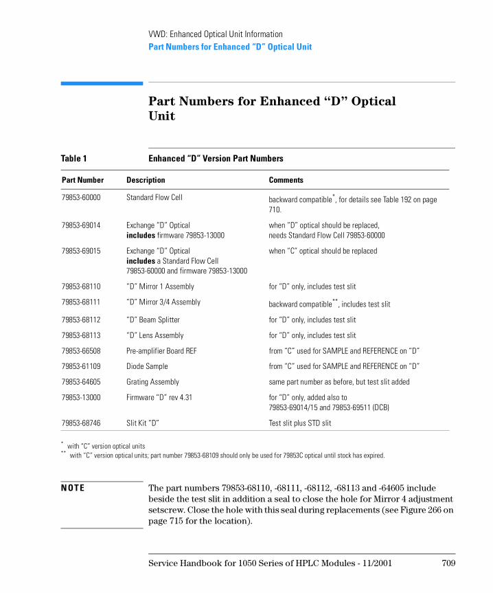
VWD: Enhanced Optical Unit InformationPart Numbers for Enhanced “D” Optical Unit
Part Numbers for Enhanced “D” Optical
Unit
N OT E The part numbers 79853-68110, -68111, -68112, -68113 and -64605 include beside the test slit in addition a seal to close the hole for Mirror 4 adjustment setscrew. Close the hole with this seal during replacements (see Figure 266 on page 715 for the location).
Table 1 Enhanced “D” Version Part Numbers
Part Number Description Comments
79853-60000 Standard Flow Cell backward compatible*, for details see Table 192 on page 710.
* with “C” version optical units
79853-69014 Exchange “D” Opticalincludes firmware 79853-13000
when “D” optical should be replaced,needs Standard Flow Cell 79853-60000
79853-69015 Exchange “D” Opticalincludes a Standard Flow Cell 79853-60000 and firmware 79853-13000
when “C” optical should be replaced
79853-68110 “D” Mirror 1 Assembly for “D” only, includes test slit
79853-68111 “D” Mirror 3/4 Assembly backward compatible**, includes test slit
** with “C” version optical units; part number 79853-68109 should only be used for 79853C optical until stock has expired.
79853-68112 “D” Beam Splitter for “D” only, includes test slit
79853-68113 “D” Lens Assembly for “D” only, includes test slit
79853-66508 Pre-amplifier Board REF from “C” used for SAMPLE and REFERENCE on “D”
79853-61109 Diode Sample from “C” used for SAMPLE and REFERENCE on “D”
79853-64605 Grating Assembly same part number as before, but test slit added
79853-13000 Firmware “D” rev 4.31 for “D” only, added also to79853-69014/15 and 79853-69511 (DCB)
79853-68746 Slit Kit “D” Test slit plus STD slit
Service Handbook for 1050 Series of HPLC Modules - 11/2001 709
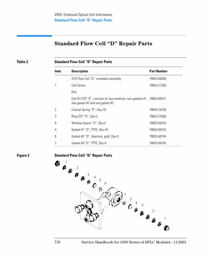
VWD: Enhanced Optical Unit InformationStandard Flow Cell “D” Repair Parts
Standard Flow Cell “D” Repair Parts
Figure 2 Standard Flow Cell “D” Repair Parts
Table 2 Standard Flow Cell “D” Repair Parts
Item Description Part Number
STD Flow Cell “D”, complete assembly 79853-60000
1 Cell Screw 79853-27200
Kits:
Cell Kit STD “D”, consists of: two windows, two gaskets #1, one gasket #2 and one gasket #3.
79853-68741
2 Conical Spring “D”, Qty=10 79853-29100
3 Ring SST “D”, Qty=2 79853-22500
5 Window Quartz “D”, Qty=2 79853-68742
4 Gasket #1 “D”, PTFE, Qty=10 79853-68743
6 Gasket #2 “D”, Aperture, gold, Qty=5 79853-68744
7 Gasket #3 “D”, PTFE, Qty=5 79853-68745
5
1
2
34
56
7
1
2
34
710 Service Handbook for 1050 Series of HPLC Modules - 11/2001
VWD: Enhanced Optical Unit InformationRepair and Mainenance
Repair and Mainenance
WA RN I N G These procedures need special knowledge on servicing the 79853C
VWD and should be done by trained Service Engineers only.
These procedures should be carried out in a room where the light can
be reduced.
Since the deuterium lamp emits intensive ultraviolet light, it is
dangerous to perform optical alignment without eye protection.
Tools required:
❏ Test Slit (supplied with mirror or grating assembly)
❏ Pozi Driv PT1
❏ hexagonal wrench (1.5 mm)
❏ hexagonal wrench (2.5 mm)
❏ pair of tweezers (not too sharp points)
Pre-requisites:
❏ Assure that the flow cell is clean, flushed with water and bubble free.
❏ Remove detector from system.
❏ Place the detector on a bench.
❏ Remove the main cover.
Service Handbook for 1050 Series of HPLC Modules - 11/2001 711
VWD: Enhanced Optical Unit InformationAdditional Information
Additional Information
For additional information about replacements and the use of the Service control Functions refer to “VWD: Maintenance Information” on page 649 and “Service Control Functions” on page 622.
Replacements and Calibrations
The following procedures describe the replacements of parts separately.
N OT E It is important that only one assembly (mirror, grating, beam splitter, ...) is changed and calibrated at a time. Otherwise you will lose correct optical assembly alignment during the calibration process.
WA RN I N G Do not remove the Entrance Slit Holder nor loosen it. Otherwise the
optical unit has to be exchanged completely.
N OT E The photocurrent readings with test slit installed are much lower than with the standard slit.
712 Service Handbook for 1050 Series of HPLC Modules - 11/2001
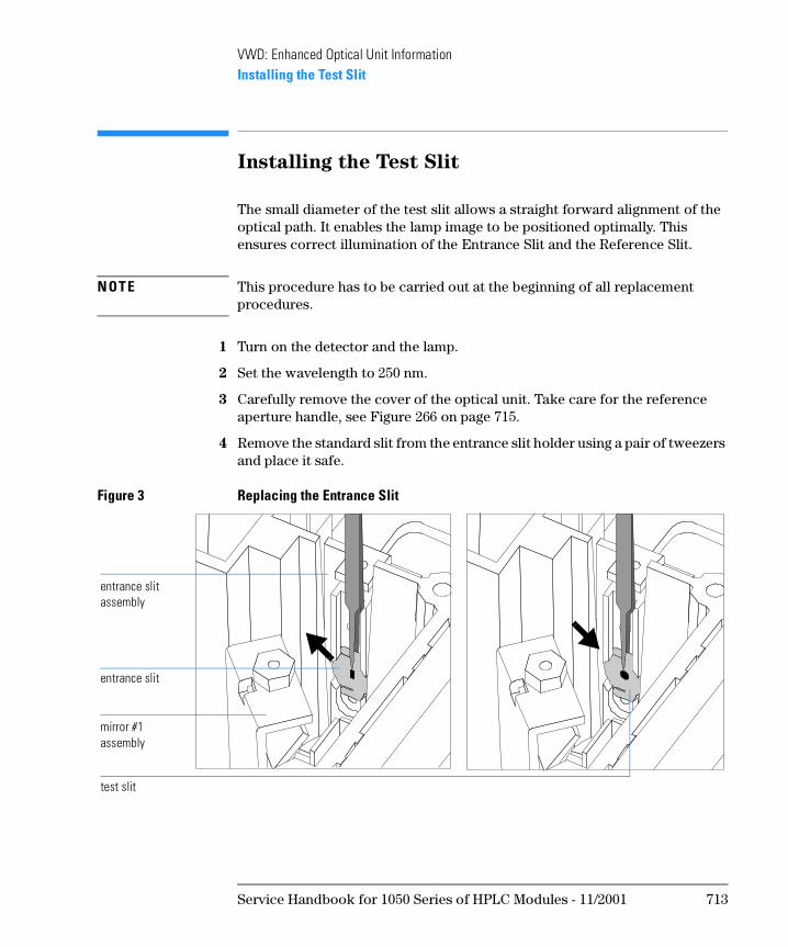
VWD: Enhanced Optical Unit InformationInstalling the Test Slit
Installing the Test Slit
The small diameter of the test slit allows a straight forward alignment of the optical path. It enables the lamp image to be positioned optimally. This ensures correct illumination of the Entrance Slit and the Reference Slit.
N OT E This procedure has to be carried out at the beginning of all replacement procedures.
1 Turn on the detector and the lamp.
2 Set the wavelength to 250 nm.
3 Carefully remove the cover of the optical unit. Take care for the reference aperture handle, see Figure 266 on page 715.
4 Remove the standard slit from the entrance slit holder using a pair of tweezers and place it safe.
Figure 3 Replacing the Entrance Slit
entrance slit assembly
entrance slit
mirror #1 assembly
test slit
Service Handbook for 1050 Series of HPLC Modules - 11/2001 713
VWD: Enhanced Optical Unit InformationInstalling the Test Slit
5 Carefully insert the test slit (with round hole) into the entrance slit holder. The slit must sit flat on the holder with the white side towards the incoming light.
714 Service Handbook for 1050 Series of HPLC Modules - 11/2001
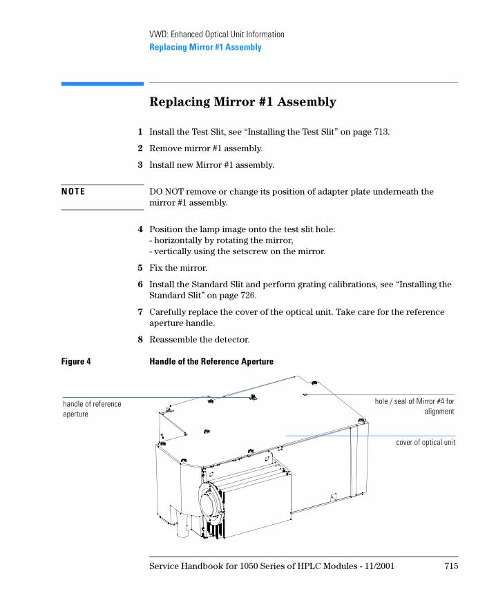
VWD: Enhanced Optical Unit InformationReplacing Mirror #1 Assembly
Replacing Mirror #1 Assembly
1 Install the Test Slit, see “Installing the Test Slit” on page 713.
2 Remove mirror #1 assembly.
3 Install new Mirror #1 assembly.
N OT E DO NOT remove or change its position of adapter plate underneath the mirror #1 assembly.
4 Position the lamp image onto the test slit hole:- horizontally by rotating the mirror,- vertically using the setscrew on the mirror.
5 Fix the mirror.
6 Install the Standard Slit and perform grating calibrations, see “Installing the Standard Slit” on page 726.
7 Carefully replace the cover of the optical unit. Take care for the reference aperture handle.
8 Reassemble the detector.
Figure 4 Handle of the Reference Aperture
handle of reference aperture
hole / seal of Mirror #4 foralignment
cover of optical unit
Service Handbook for 1050 Series of HPLC Modules - 11/2001 715
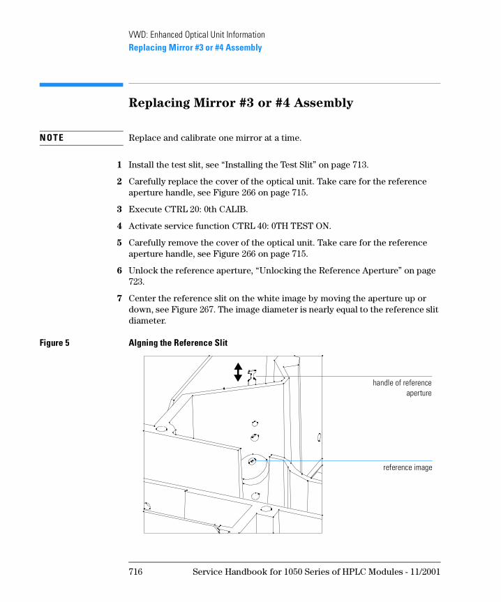
VWD: Enhanced Optical Unit InformationReplacing Mirror #3 or #4 Assembly
Replacing Mirror #3 or #4 Assembly
N OT E Replace and calibrate one mirror at a time.
1 Install the test slit, see “Installing the Test Slit” on page 713.
2 Carefully replace the cover of the optical unit. Take care for the reference aperture handle, see Figure 266 on page 715.
3 Execute CTRL 20: 0th CALIB.
4 Activate service function CTRL 40: 0TH TEST ON.
5 Carefully remove the cover of the optical unit. Take care for the reference aperture handle, see Figure 266 on page 715.
6 Unlock the reference aperture, “Unlocking the Reference Aperture” on page 723.
7 Center the reference slit on the white image by moving the aperture up or down, see Figure 267. The image diameter is nearly equal to the reference slit diameter.
Figure 5 Algning the Reference Slit
handle of referenceaperture
reference image
716 Service Handbook for 1050 Series of HPLC Modules - 11/2001
VWD: Enhanced Optical Unit InformationReplacing Mirror #3 or #4 Assembly
8 Install new mirror #3 or #4 assembly.
9 Position the white image precisely onto the reference slit:- horizontally by rotating the mirror,- vertically using the setscrew of the mirror
10 Carefully replace the cover of the optical unit. Take care for the reference aperture handle.
11 De-activate CTRL 40: 0TH TEST OFF, press CLEAR, CLEAR and BALANCE.
12 Set λ=250 nm.
13 Activate CTRL 16: PHOTOCURRENT.
14 Optimize the sample readings using the setscrew of mirror #4 through the hole in the optical unit cover, see Figure 266 on page 715.
15 Optimize the reference readings with the reference aperture, see “Optimizing the Reference Readings” on page 725.
16 Install the standard slit and perform electronic calibrations, see “Installing the Standard Slit” on page 726.
Service Handbook for 1050 Series of HPLC Modules - 11/2001 717
VWD: Enhanced Optical Unit InformationReplacing the Grating or Grating Motor
Replacing the Grating or Grating Motor
N OT E To replace the Grating and/or the Grating Motor refer to “Replacing Grating
Assembly Parts” on page 668 and continue with the Alignment Procedure below.
1 Install the test slit, see “Installing the Test Slit” on page 713.
2 Carefully replace the cover of the optical unit. Take care for the reference aperture handle, see Figure 266 on page 715.
3 Execute CTRL 20: 0th CALIB.
4 Activate service function CTRL 40: 0TH TEST ON.
5 Carefully remove the cover of the optical unit. Take care for the reference aperture handle, see Figure 266 on page 715.
6 Unlock the reference aperture, see “Unlocking the Reference Aperture” on page 723.
7 De-activate CTRL 40: 0TH TEST OFF.
8 Center the reference slit on the white image by moving the aperture up or down. The image diameter is nearly equal to the reference slit diameter.
9 Remove the grating and reassemble new grating.
N OT E Assure that the grating is not fixed on the shaft with the setscrew.
10 Set the Param. λ=200, using service function CTRL 31: SET λ PARAM.
11 Activate service function CTRL 40: 0TH TEST ON.
12 Turn the grating so that the center of the image is on the reference slit (a small horizontal and vertical deviation can be accepted).
13 Fix the grating with the setscrew.
14 De-activate and re-activate CTRL 40: 0TH TEST and check the position of the image on the reference slit.
If not correct, loosen the grating and repeat steps 12 to 14.
718 Service Handbook for 1050 Series of HPLC Modules - 11/2001
VWD: Enhanced Optical Unit InformationReplacing the Grating or Grating Motor
15 Do a vertical adjustment with Mirror #4 for precise vertical fit of image on reference slit, using the setscrew of mirror #4 through the hole in the optical unit cover, see Figure 266 on page 715.
16 Carefully replace the cover of the optical unit. Take care for the reference aperture handle.
17 De-activate CTRL 40: 0TH TEST OFF, press [CLEAR], [CLEAR] and [BALANCE].
18 Execute CTRL 20: 0th CALIB.
19 Activate CTRL 40: 0TH TEST ON and readjust the Beam Splitter for ideal horizontal fit.
20 De-activate CTRL 40: 0TH TEST OFF.
21 Set λ=250 nm.
22 Activate CTRL 16: PHOTOCURRENT.
23 Optimize the sample readings, using the setscrew of mirror #4 through the hole in the optical unit cover, see Figure 266 on page 715.
24 Unlock the reference aperture, see “Unlocking the Reference Aperture” on page 723.
25 Optimize the reference readings with the reference slit, see “Optimizing the Reference Readings” on page 725.
26 Install the standard slit and perform electronic calibrations, see “Installing the Standard Slit” on page 726.
Service Handbook for 1050 Series of HPLC Modules - 11/2001 719
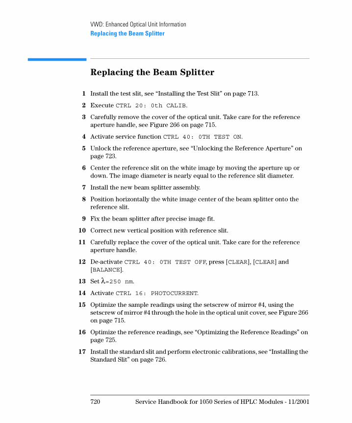
VWD: Enhanced Optical Unit InformationReplacing the Beam Splitter
Replacing the Beam Splitter
1 Install the test slit, see “Installing the Test Slit” on page 713.
2 Execute CTRL 20: 0th CALIB.
3 Carefully remove the cover of the optical unit. Take care for the reference aperture handle, see Figure 266 on page 715.
4 Activate service function CTRL 40: 0TH TEST ON.
5 Unlock the reference aperture, see “Unlocking the Reference Aperture” on page 723.
6 Center the reference slit on the white image by moving the aperture up or down. The image diameter is nearly equal to the reference slit diameter.
7 Install the new beam splitter assembly.
8 Position horizontally the white image center of the beam splitter onto the reference slit.
9 Fix the beam splitter after precise image fit.
10 Correct new vertical position with reference slit.
11 Carefully replace the cover of the optical unit. Take care for the reference aperture handle.
12 De-activate CTRL 40: 0TH TEST OFF, press [CLEAR], [CLEAR] and [BALANCE].
13 Set λ=250 nm.
14 Activate CTRL 16: PHOTOCURRENT.
15 Optimize the sample readings using the setscrew of mirror #4, using the setscrew of mirror #4 through the hole in the optical unit cover, see Figure 266 on page 715.
16 Optimize the reference readings, see “Optimizing the Reference Readings” on page 725.
17 Install the standard slit and perform electronic calibrations, see “Installing the Standard Slit” on page 726.
720 Service Handbook for 1050 Series of HPLC Modules - 11/2001
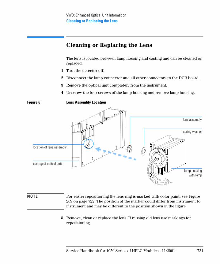
VWD: Enhanced Optical Unit InformationCleaning or Replacing the Lens
Cleaning or Replacing the Lens
The lens is located between lamp housing and casting and can be cleaned or replaced.
1 Turn the detector off.
2 Disconnect the lamp connector and all other connectors to the DCB board.
3 Remove the optical unit completely from the instrument.
4 Unscrew the four screws of the lamp housing and remove lamp housing.
Figure 6 Lens Assembly Location
N OT E For easier repositioning the lens ring is marked with color paint, see Figure 269 on page 722. The position of the marker could differ from instrument to instrument and may be different to the position shown in the figure.
5 Remove, clean or replace the lens. If reusing old lens use markings for repositioning.
location of lens assembly
casting of optical unit
lamp housingwith lamp
spring washer
lens assembly
Service Handbook for 1050 Series of HPLC Modules - 11/2001 721
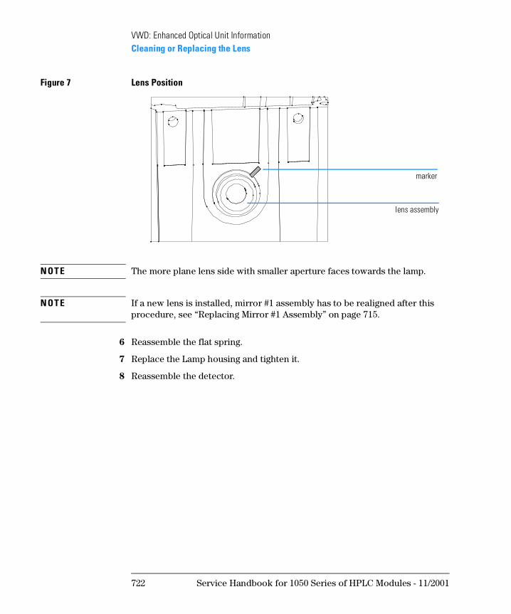
VWD: Enhanced Optical Unit InformationCleaning or Replacing the Lens
Figure 7 Lens Position
N OT E The more plane lens side with smaller aperture faces towards the lamp.
N OT E If a new lens is installed, mirror #1 assembly has to be realigned after this procedure, see “Replacing Mirror #1 Assembly” on page 715.
6 Reassemble the flat spring.
7 Replace the Lamp housing and tighten it.
8 Reassemble the detector.
marker
lens assembly
722 Service Handbook for 1050 Series of HPLC Modules - 11/2001
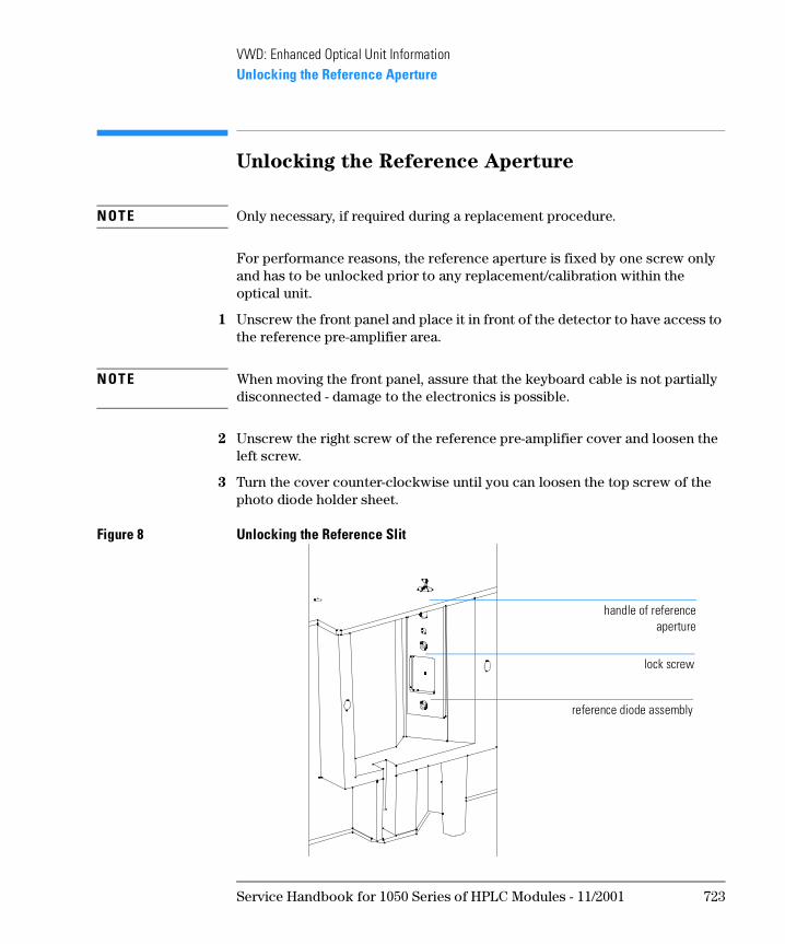
VWD: Enhanced Optical Unit InformationUnlocking the Reference Aperture
Unlocking the Reference Aperture
N OT E Only necessary, if required during a replacement procedure.
For performance reasons, the reference aperture is fixed by one screw only and has to be unlocked prior to any replacement/calibration within the optical unit.
1 Unscrew the front panel and place it in front of the detector to have access to the reference pre-amplifier area.
N OT E When moving the front panel, assure that the keyboard cable is not partially disconnected - damage to the electronics is possible.
2 Unscrew the right screw of the reference pre-amplifier cover and loosen the left screw.
3 Turn the cover counter-clockwise until you can loosen the top screw of the photo diode holder sheet.
Figure 8 Unlocking the Reference Slit
handle of referenceaperture
lock screw
reference diode assembly
Service Handbook for 1050 Series of HPLC Modules - 11/2001 723
VWD: Enhanced Optical Unit InformationUnlocking the Reference Aperture
4 Replace the reference pre-amplifier cover (to prevent stray light).
5 Fit the front panel with one screw at the right of the mainframe.
6 Turn on the detector and the lamp
7 Set wavelength to 250 nm.
8 Return to your replacement procedure.
724 Service Handbook for 1050 Series of HPLC Modules - 11/2001
VWD: Enhanced Optical Unit InformationOptimizing the Reference Readings
Optimizing the Reference Readings
1 Carefully replace the cover of the optical unit. Take care for the reference aperture handle.
2 Activate CTRL 16: PHOTOCURRENT.
3 Shift reference aperture vertically for maximum reference readings.
4 Fix the reference slit with the top lock screw of the photo diode assembly.
5 Replace the reference photodiode cover.
6 Continue with the next step of the procedure of the assembly you are replacing.
Figure 9 Optimizing the Reference Readings
handle of referenceaperture
lock screw
reference diode assembly
Service Handbook for 1050 Series of HPLC Modules - 11/2001 725
VWD: Enhanced Optical Unit InformationInstalling the Standard Slit
Installing the Standard Slit
N OT E This procedure has to be carried out at the end of all replacement procedures.
1 Carefully remove the cover of the optical unit. Take care for the reference aperture handle, see Figure 266 on page 715.
2 Remove the test slit from the entrance slit holder using a pair of tweezers and place it safe.
Figure 10 Replacing the Entrance Slit
3 Carefully insert the standard slit into the entrance slit holder. The slit must sit plane on the holder.
4 Carefully replace the cover of the optical unit. Take care for the reference aperture handle, see Figure 266 on page 715.
5 Execute CTRL 20: 0th CALIB.
6 Execute CTRL 21: l CALIBRATION.
7 Reassemble the detector.
entrance slit assembly
test slit
mirror #1 assembly
standard slit
726 Service Handbook for 1050 Series of HPLC Modules - 11/2001

1
1 VWD: Additional Information
This chapter provides additional information about the 1050 Variable Wavelength Detectors
VWD: Additional Information
Since the introduction of the 79853C Variable Wavelength Detector in 1991, the following hardware and firmware changes have been implemented.
728 Service Handbook for 1050 Series of HPLC Modules - 11/2001
VWD: Additional InformationProduct History
Product History
Since introduction of the 79853C Variable Wavelength Detector in January 1992 following changes have been implemented.
Prefix Changes
Table 1 Prefix Changes
Serial Number Changes Additional Information
3145 J 00101 Start of customer shipments ∅
3152 J 00263 New amplification factor of reference side due to high output of new DAD lamps.
See “Modified Pre-Amplifier Gain” on page 734.
3152 J 00489 Introduction of DCB firmware revision 4.22
See “SN 01050-055” on page 734.
3217 J 00603 Introduction of DCB firmware revision 4.23
See “SN 01050-055” on page 734.
3225 J 00773 Introduction of DCB firmware revision 4.24
See “SN 01050-055” on page 734.
3225 J 01801 Introduction of PTFE ring in optical unit
See “SN 01050-068” on page 734.
Volume changes on Preparative Flow Cell in September 1992
See Table 138 on page 574 and Table 187 on page 698.
3225 J 02011 Introduction of new DCB/PSC boards See “SN 01050-072” on page 734.
3323 J 03117 Introduction of new lamp housing
3334 J 03255 Change of manufacturing process for photo diodes mounting
to improve stability against humidity
Ultra High Pressure cell replaced High Pressure Cell in 1993
Service Handbook for 1050 Series of HPLC Modules - 11/2001 729
VWD: Additional InformationProduct History
3522 J 04305 Enhanced optical unit “D” with STD flow cell “D” in June 1995
to improve temperature stability, see “VWD: Enhanced Optical Unit Information” on page 705
Table 1 Prefix Changes
Serial Number Changes Additional Information
730 Service Handbook for 1050 Series of HPLC Modules - 11/2001
VWD: Additional InformationDCB ROM Firmware Revisions
DCB ROM Firmware Revisions
Table 2 DCB ROM Firmware Revisions
Revision Major Changes Comments
4.08 Used for first internal Waldbronn/Avondale units and some demo units.
4.09 PHOENIX problem: won’t stop when running with A/D Concerter (for example ABORT).
Not released.Used for internal Waldbronn/Avondale tests.
4.21 CTRL 45 COMPENSATE bug fix, calibrated wavelength deviation might exceed the specification. CTRL 22 HOLMIUMCHECK for GLP reasons added.
Released for 79853C in January 1992.For replacements use part number 79853-13005 (4.24). NEEDS GPIB ROM version 0.20 or above (79853-13004)
4.22 New algorithm for CTRL 45 COMPENSATE and CTRL 22 HOLMIUMCHECK.
Released for 79853C in March 1992. Started with serial number 3152J00489.For replacements use part number 79853-13005 (4.24). NEEDS GPIB ROM version 0.20 or above (79853-13004)
4.23 Removed bug: Incorrect wavelength setting during stepper motor intialisation bewteen 536.4 nm and 600 nm.
Released for 79853C in April 1992. Started with serial number 3217J00603.For replacements use part number 79853-13005 (4.24).NEEDS GPIB ROM version 0.20 or above (79853-13004)
Service Handbook for 1050 Series of HPLC Modules - 11/2001 731
VWD: Additional InformationDCB ROM Firmware Revisions
4.24 Removed bug : EEROM DATA LOST1Removed bug : Wavelength accuracy between 360 nm and 486 nm
Released for 79853C in June 1992. Started with serial number 3225J00773.For replacements use part number 79853-13005 (4.24).NEEDS GPIB ROM version 0.20 or above (79853-13004)
4.31 For Enhanced Optical Unit “D” only Released for 79853C in June 1995. Started with serial number 3522J04305.For replacements use part number 79853-13000 (4.31).NEEDS GPIB ROM version 0.20 or above (79853-13004)
Table 2 DCB ROM Firmware Revisions
Revision Major Changes Comments
732 Service Handbook for 1050 Series of HPLC Modules - 11/2001
VWD: Additional InformationGPIB ROM Firmware Revisions
GPIB ROM Firmware Revisions
The table below lists all GPIB ROM firmware revisions for the 79853A/C.
Table 3 GPIB ROM Revisions
Revision Major Changes Comments
0.04 First official realease for 79853A.
0.05 LC APPACK problem: BUFFER OVERFLOW message preventing run buffer overflow.
Released for 79853A.
0.08 Also useable for 79853C. PHOENIX problem: prevents hang-ups at power on (if VWD is switched on after PHOENIX has been switched on).
Released for 79853A and 79853C. For replacements use part number 79853-13004 (0.2X)
0.09 PHOENIX problem: prevents VECTRA 486 hang-ups.
NOT officially released.
0.20 additional changes for future PHOENIX enhancements.
Released for 79853A and 79853C in January 1992.Required for 79853C firmware revision 4.21 and above.For replacements use part number 79853-13004 (0.2X)
Service Handbook for 1050 Series of HPLC Modules - 11/2001 733
VWD: Additional InformationHardware Changes and Service Notes
Hardware Changes and Service Notes
Modified Pre-Amplifier Gain
First instruments where shipped with a pre-amplifier gain of 100% on the reference side. The new deuterium lamps (79883-60002) showed sometimes very high energies which gave very high numbers on the reference side 16:PHOTOCURRENT. To prevent an overload the amplification factor was changed to 75%. The feedback resistors on the reference side changed from 200 MOhm to 150 MOhm and on the sample side from 100 MOhm to 75 MOhm.
N OT E No revision change was made. The modified pre-amplifiers started with serial number 3145J00263.
Important Service Note
SN 01050-055 Service Note 1050-055 describes the introduction of the DCB firmware revision 4.24 and the problems with previous revisions in more detail.
SN 01050-068 This note describes problems with POM ring between lamp housing and optical casting. Exchange POM ring against PTFE Ring 53C (79853-24500).
SN 01050-072 This note describes problems with negative baseline jumps on analog output signal. New DCB (79853-66511) and PSC (79853-66512) Boards have been introduced.
SN 01050-085 This note describes the optimization for drift problems.
SN 01050-104 Introduction of Enhanced Optical Unit, see “VWD: Enhanced Optical Unit
Information” on page 705.
SN 01050-107 Cuvette Holder for Wavelength Verification with Certified Standard Solutions available see “Cuvette Holder” on page 700.
SN 01050-112 Check of photometric accuracy - information on path lengths of flow cells, see “Correction factors for 79853C flow cells” on page 575.
734 Service Handbook for 1050 Series of HPLC Modules - 11/2001

��
In This Book
This manual contains technical information about the Agilent 1050 liquid chromatographs.
This manual is available as electronic version (Adobe Acrobat Reader file) only.